WO2023073467A1 - Batterie flexible et dispositif électronique - Google Patents
Batterie flexible et dispositif électronique Download PDFInfo
- Publication number
- WO2023073467A1 WO2023073467A1 PCT/IB2022/059765 IB2022059765W WO2023073467A1 WO 2023073467 A1 WO2023073467 A1 WO 2023073467A1 IB 2022059765 W IB2022059765 W IB 2022059765W WO 2023073467 A1 WO2023073467 A1 WO 2023073467A1
- Authority
- WO
- WIPO (PCT)
- Prior art keywords
- current collector
- carbon
- active material
- flexible battery
- graphene
- Prior art date
Links
- OKTJSMMVPCPJKN-UHFFFAOYSA-N Carbon Chemical compound [C] OKTJSMMVPCPJKN-UHFFFAOYSA-N 0.000 claims abstract description 315
- 239000000463 material Substances 0.000 claims abstract description 192
- 229910052799 carbon Inorganic materials 0.000 claims abstract description 142
- 239000007774 positive electrode material Substances 0.000 claims abstract description 48
- 239000007773 negative electrode material Substances 0.000 claims abstract description 36
- 229910021389 graphene Inorganic materials 0.000 claims description 239
- -1 graphene compound Chemical class 0.000 claims description 180
- 238000000034 method Methods 0.000 claims description 47
- 229920000049 Carbon (fiber) Polymers 0.000 claims description 43
- 239000004917 carbon fiber Substances 0.000 claims description 43
- 238000005452 bending Methods 0.000 claims description 35
- 239000011164 primary particle Substances 0.000 claims description 12
- 239000011163 secondary particle Substances 0.000 claims description 11
- 239000010408 film Substances 0.000 description 155
- 239000011149 active material Substances 0.000 description 136
- 239000010410 layer Substances 0.000 description 135
- 238000010438 heat treatment Methods 0.000 description 104
- PXHVJJICTQNCMI-UHFFFAOYSA-N Nickel Chemical compound [Ni] PXHVJJICTQNCMI-UHFFFAOYSA-N 0.000 description 90
- 239000007864 aqueous solution Substances 0.000 description 56
- PQXKHYXIUOZZFA-UHFFFAOYSA-M lithium fluoride Chemical compound [Li+].[F-] PQXKHYXIUOZZFA-UHFFFAOYSA-M 0.000 description 56
- 239000002131 composite material Substances 0.000 description 54
- YCKRFDGAMUMZLT-UHFFFAOYSA-N Fluorine atom Chemical compound [F] YCKRFDGAMUMZLT-UHFFFAOYSA-N 0.000 description 48
- 229910052731 fluorine Inorganic materials 0.000 description 48
- 239000011737 fluorine Substances 0.000 description 48
- 229910052759 nickel Inorganic materials 0.000 description 46
- 229910017052 cobalt Inorganic materials 0.000 description 44
- 239000010941 cobalt Substances 0.000 description 44
- GUTLYIVDDKVIGB-UHFFFAOYSA-N cobalt atom Chemical compound [Co] GUTLYIVDDKVIGB-UHFFFAOYSA-N 0.000 description 43
- 229910052744 lithium Inorganic materials 0.000 description 41
- 239000004020 conductor Substances 0.000 description 40
- WHXSMMKQMYFTQS-UHFFFAOYSA-N Lithium Chemical compound [Li] WHXSMMKQMYFTQS-UHFFFAOYSA-N 0.000 description 39
- 239000000203 mixture Substances 0.000 description 37
- 238000006243 chemical reaction Methods 0.000 description 35
- 238000004049 embossing Methods 0.000 description 35
- 239000011777 magnesium Substances 0.000 description 34
- 239000000654 additive Substances 0.000 description 33
- 230000000996 additive effect Effects 0.000 description 33
- 229910052782 aluminium Inorganic materials 0.000 description 32
- QVGXLLKOCUKJST-UHFFFAOYSA-N atomic oxygen Chemical compound [O] QVGXLLKOCUKJST-UHFFFAOYSA-N 0.000 description 32
- 229910052760 oxygen Inorganic materials 0.000 description 32
- 239000001301 oxygen Substances 0.000 description 32
- 150000002500 ions Chemical class 0.000 description 31
- 239000011572 manganese Substances 0.000 description 31
- FYYHWMGAXLPEAU-UHFFFAOYSA-N Magnesium Chemical compound [Mg] FYYHWMGAXLPEAU-UHFFFAOYSA-N 0.000 description 30
- 229910052749 magnesium Inorganic materials 0.000 description 30
- 229910052748 manganese Inorganic materials 0.000 description 30
- 150000001875 compounds Chemical class 0.000 description 29
- 229910052723 transition metal Inorganic materials 0.000 description 29
- 150000003624 transition metals Chemical class 0.000 description 29
- PWHULOQIROXLJO-UHFFFAOYSA-N Manganese Chemical compound [Mn] PWHULOQIROXLJO-UHFFFAOYSA-N 0.000 description 28
- 229910002804 graphite Inorganic materials 0.000 description 28
- 239000010439 graphite Substances 0.000 description 28
- VNWKTOKETHGBQD-UHFFFAOYSA-N methane Chemical compound C VNWKTOKETHGBQD-UHFFFAOYSA-N 0.000 description 28
- XAGFODPZIPBFFR-UHFFFAOYSA-N aluminium Chemical compound [Al] XAGFODPZIPBFFR-UHFFFAOYSA-N 0.000 description 26
- 239000003792 electrolyte Substances 0.000 description 26
- 238000004519 manufacturing process Methods 0.000 description 25
- 239000012298 atmosphere Substances 0.000 description 24
- 239000011230 binding agent Substances 0.000 description 23
- 229910052751 metal Inorganic materials 0.000 description 23
- 239000002184 metal Substances 0.000 description 23
- 230000001965 increasing effect Effects 0.000 description 22
- HBBGRARXTFLTSG-UHFFFAOYSA-N Lithium ion Chemical compound [Li+] HBBGRARXTFLTSG-UHFFFAOYSA-N 0.000 description 21
- 229910001416 lithium ion Inorganic materials 0.000 description 21
- WMFOQBRAJBCJND-UHFFFAOYSA-M Lithium hydroxide Chemical compound [Li+].[OH-] WMFOQBRAJBCJND-UHFFFAOYSA-M 0.000 description 20
- 239000008151 electrolyte solution Substances 0.000 description 20
- 239000007788 liquid Substances 0.000 description 20
- 238000002156 mixing Methods 0.000 description 20
- 239000006185 dispersion Substances 0.000 description 19
- 230000006870 function Effects 0.000 description 19
- 230000000694 effects Effects 0.000 description 17
- 238000000576 coating method Methods 0.000 description 16
- 239000002904 solvent Substances 0.000 description 16
- 239000000758 substrate Substances 0.000 description 16
- 229910015118 LiMO Inorganic materials 0.000 description 15
- 239000011248 coating agent Substances 0.000 description 15
- 238000006722 reduction reaction Methods 0.000 description 15
- VTYYLEPIZMXCLO-UHFFFAOYSA-L Calcium carbonate Chemical compound [Ca+2].[O-]C([O-])=O VTYYLEPIZMXCLO-UHFFFAOYSA-L 0.000 description 14
- 239000004743 Polypropylene Substances 0.000 description 14
- 229920001155 polypropylene Polymers 0.000 description 14
- XLYOFNOQVPJJNP-UHFFFAOYSA-N water Substances O XLYOFNOQVPJJNP-UHFFFAOYSA-N 0.000 description 14
- 229940043430 calcium compound Drugs 0.000 description 13
- 150000001674 calcium compounds Chemical class 0.000 description 13
- CSCPPACGZOOCGX-UHFFFAOYSA-N Acetone Chemical compound CC(C)=O CSCPPACGZOOCGX-UHFFFAOYSA-N 0.000 description 12
- 239000012535 impurity Substances 0.000 description 12
- TWNQGVIAIRXVLR-UHFFFAOYSA-N oxo(oxoalumanyloxy)alumane Chemical compound O=[Al]O[Al]=O TWNQGVIAIRXVLR-UHFFFAOYSA-N 0.000 description 12
- 239000002245 particle Substances 0.000 description 12
- 239000011148 porous material Substances 0.000 description 12
- 230000009467 reduction Effects 0.000 description 12
- LIVNPJMFVYWSIS-UHFFFAOYSA-N silicon monoxide Chemical compound [Si-]#[O+] LIVNPJMFVYWSIS-UHFFFAOYSA-N 0.000 description 12
- 125000004429 atom Chemical group 0.000 description 11
- 238000010586 diagram Methods 0.000 description 11
- 125000000524 functional group Chemical group 0.000 description 11
- 238000002844 melting Methods 0.000 description 11
- 230000008018 melting Effects 0.000 description 11
- 239000002002 slurry Substances 0.000 description 11
- CIWBSHSKHKDKBQ-JLAZNSOCSA-N Ascorbic acid Chemical compound OC[C@H](O)[C@H]1OC(=O)C(O)=C1O CIWBSHSKHKDKBQ-JLAZNSOCSA-N 0.000 description 10
- HFCVPDYCRZVZDF-UHFFFAOYSA-N [Li+].[Co+2].[Ni+2].[O-][Mn]([O-])(=O)=O Chemical compound [Li+].[Co+2].[Ni+2].[O-][Mn]([O-])(=O)=O HFCVPDYCRZVZDF-UHFFFAOYSA-N 0.000 description 10
- 238000000975 co-precipitation Methods 0.000 description 10
- 239000013078 crystal Substances 0.000 description 10
- 239000011888 foil Substances 0.000 description 10
- 239000004570 mortar (masonry) Substances 0.000 description 10
- LFQSCWFLJHTTHZ-UHFFFAOYSA-N Ethanol Chemical compound CCO LFQSCWFLJHTTHZ-UHFFFAOYSA-N 0.000 description 9
- 150000001450 anions Chemical class 0.000 description 9
- 230000015572 biosynthetic process Effects 0.000 description 9
- 239000003638 chemical reducing agent Substances 0.000 description 9
- 238000004140 cleaning Methods 0.000 description 9
- 229910001635 magnesium fluoride Inorganic materials 0.000 description 9
- 230000007935 neutral effect Effects 0.000 description 9
- 238000003825 pressing Methods 0.000 description 9
- 238000003756 stirring Methods 0.000 description 9
- IJGRMHOSHXDMSA-UHFFFAOYSA-N Atomic nitrogen Chemical compound N#N IJGRMHOSHXDMSA-UHFFFAOYSA-N 0.000 description 8
- KMTRUDSVKNLOMY-UHFFFAOYSA-N Ethylene carbonate Chemical compound O=C1OCCO1 KMTRUDSVKNLOMY-UHFFFAOYSA-N 0.000 description 8
- XEEYBQQBJWHFJM-UHFFFAOYSA-N Iron Chemical compound [Fe] XEEYBQQBJWHFJM-UHFFFAOYSA-N 0.000 description 8
- 239000012790 adhesive layer Substances 0.000 description 8
- 238000001035 drying Methods 0.000 description 8
- JBTWLSYIZRCDFO-UHFFFAOYSA-N ethyl methyl carbonate Chemical compound CCOC(=O)OC JBTWLSYIZRCDFO-UHFFFAOYSA-N 0.000 description 8
- 210000001061 forehead Anatomy 0.000 description 8
- 229920005989 resin Polymers 0.000 description 8
- 239000011347 resin Substances 0.000 description 8
- 235000002639 sodium chloride Nutrition 0.000 description 8
- 238000001694 spray drying Methods 0.000 description 8
- OYPRJOBELJOOCE-UHFFFAOYSA-N Calcium Chemical compound [Ca] OYPRJOBELJOOCE-UHFFFAOYSA-N 0.000 description 7
- SECXISVLQFMRJM-UHFFFAOYSA-N N-Methylpyrrolidone Chemical compound CN1CCCC1=O SECXISVLQFMRJM-UHFFFAOYSA-N 0.000 description 7
- 239000004698 Polyethylene Substances 0.000 description 7
- 229910021383 artificial graphite Inorganic materials 0.000 description 7
- 229910052791 calcium Inorganic materials 0.000 description 7
- 239000011575 calcium Substances 0.000 description 7
- 229910000019 calcium carbonate Inorganic materials 0.000 description 7
- 150000001768 cations Chemical class 0.000 description 7
- 229920002678 cellulose Chemical class 0.000 description 7
- 239000001913 cellulose Chemical class 0.000 description 7
- 238000001816 cooling Methods 0.000 description 7
- 239000010949 copper Substances 0.000 description 7
- 238000000354 decomposition reaction Methods 0.000 description 7
- 238000007599 discharging Methods 0.000 description 7
- 210000003128 head Anatomy 0.000 description 7
- 150000002642 lithium compounds Chemical class 0.000 description 7
- ORUIBWPALBXDOA-UHFFFAOYSA-L magnesium fluoride Chemical compound [F-].[F-].[Mg+2] ORUIBWPALBXDOA-UHFFFAOYSA-L 0.000 description 7
- 239000012071 phase Substances 0.000 description 7
- 229920000573 polyethylene Polymers 0.000 description 7
- 239000002861 polymer material Substances 0.000 description 7
- 239000002243 precursor Substances 0.000 description 7
- 239000000243 solution Substances 0.000 description 7
- 239000000126 substance Substances 0.000 description 7
- WEVYAHXRMPXWCK-UHFFFAOYSA-N Acetonitrile Chemical compound CC#N WEVYAHXRMPXWCK-UHFFFAOYSA-N 0.000 description 6
- IAZDPXIOMUYVGZ-UHFFFAOYSA-N Dimethylsulphoxide Chemical compound CS(C)=O IAZDPXIOMUYVGZ-UHFFFAOYSA-N 0.000 description 6
- ZMXDDKWLCZADIW-UHFFFAOYSA-N N,N-Dimethylformamide Chemical compound CN(C)C=O ZMXDDKWLCZADIW-UHFFFAOYSA-N 0.000 description 6
- 239000004677 Nylon Substances 0.000 description 6
- 239000002033 PVDF binder Substances 0.000 description 6
- KWYUFKZDYYNOTN-UHFFFAOYSA-M Potassium hydroxide Chemical compound [OH-].[K+] KWYUFKZDYYNOTN-UHFFFAOYSA-M 0.000 description 6
- HEMHJVSKTPXQMS-UHFFFAOYSA-M Sodium hydroxide Chemical compound [OH-].[Na+] HEMHJVSKTPXQMS-UHFFFAOYSA-M 0.000 description 6
- WYURNTSHIVDZCO-UHFFFAOYSA-N Tetrahydrofuran Chemical compound C1CCOC1 WYURNTSHIVDZCO-UHFFFAOYSA-N 0.000 description 6
- 239000000956 alloy Substances 0.000 description 6
- 229920003235 aromatic polyamide Polymers 0.000 description 6
- 239000002041 carbon nanotube Substances 0.000 description 6
- 229910021393 carbon nanotube Inorganic materials 0.000 description 6
- 239000003575 carbonaceous material Substances 0.000 description 6
- 238000004891 communication Methods 0.000 description 6
- 229910052802 copper Inorganic materials 0.000 description 6
- 238000005520 cutting process Methods 0.000 description 6
- IEJIGPNLZYLLBP-UHFFFAOYSA-N dimethyl carbonate Chemical compound COC(=O)OC IEJIGPNLZYLLBP-UHFFFAOYSA-N 0.000 description 6
- 239000000835 fiber Substances 0.000 description 6
- 150000004677 hydrates Chemical class 0.000 description 6
- 239000011229 interlayer Substances 0.000 description 6
- 229920001778 nylon Polymers 0.000 description 6
- 239000003960 organic solvent Substances 0.000 description 6
- 229920002647 polyamide Polymers 0.000 description 6
- 229920002981 polyvinylidene fluoride Polymers 0.000 description 6
- 238000007789 sealing Methods 0.000 description 6
- 239000007784 solid electrolyte Substances 0.000 description 6
- 239000002344 surface layer Substances 0.000 description 6
- 229920003169 water-soluble polymer Polymers 0.000 description 6
- 229920002134 Carboxymethyl cellulose Polymers 0.000 description 5
- RYGMFSIKBFXOCR-UHFFFAOYSA-N Copper Chemical compound [Cu] RYGMFSIKBFXOCR-UHFFFAOYSA-N 0.000 description 5
- 229920003171 Poly (ethylene oxide) Polymers 0.000 description 5
- NINIDFKCEFEMDL-UHFFFAOYSA-N Sulfur Chemical compound [S] NINIDFKCEFEMDL-UHFFFAOYSA-N 0.000 description 5
- 229910045601 alloy Inorganic materials 0.000 description 5
- 239000004760 aramid Substances 0.000 description 5
- 239000011668 ascorbic acid Substances 0.000 description 5
- 229960005070 ascorbic acid Drugs 0.000 description 5
- 235000010323 ascorbic acid Nutrition 0.000 description 5
- 230000005540 biological transmission Effects 0.000 description 5
- 239000006229 carbon black Substances 0.000 description 5
- 239000002134 carbon nanofiber Substances 0.000 description 5
- 229920001971 elastomer Polymers 0.000 description 5
- 239000011267 electrode slurry Substances 0.000 description 5
- WPBNNNQJVZRUHP-UHFFFAOYSA-L manganese(2+);methyl n-[[2-(methoxycarbonylcarbamothioylamino)phenyl]carbamothioyl]carbamate;n-[2-(sulfidocarbothioylamino)ethyl]carbamodithioate Chemical compound [Mn+2].[S-]C(=S)NCCNC([S-])=S.COC(=O)NC(=S)NC1=CC=CC=C1NC(=S)NC(=O)OC WPBNNNQJVZRUHP-UHFFFAOYSA-L 0.000 description 5
- 229910021382 natural graphite Inorganic materials 0.000 description 5
- 230000003287 optical effect Effects 0.000 description 5
- RVTZCBVAJQQJTK-UHFFFAOYSA-N oxygen(2-);zirconium(4+) Chemical compound [O-2].[O-2].[Zr+4] RVTZCBVAJQQJTK-UHFFFAOYSA-N 0.000 description 5
- 239000000843 powder Substances 0.000 description 5
- 230000008569 process Effects 0.000 description 5
- 239000005060 rubber Substances 0.000 description 5
- 229910052710 silicon Inorganic materials 0.000 description 5
- 239000010703 silicon Substances 0.000 description 5
- 229910052717 sulfur Inorganic materials 0.000 description 5
- 239000011593 sulfur Substances 0.000 description 5
- 229910001928 zirconium oxide Inorganic materials 0.000 description 5
- OAKJQQAXSVQMHS-UHFFFAOYSA-N Hydrazine Chemical compound NN OAKJQQAXSVQMHS-UHFFFAOYSA-N 0.000 description 4
- UFHFLCQGNIYNRP-UHFFFAOYSA-N Hydrogen Chemical compound [H][H] UFHFLCQGNIYNRP-UHFFFAOYSA-N 0.000 description 4
- QIGBRXMKCJKVMJ-UHFFFAOYSA-N Hydroquinone Chemical compound OC1=CC=C(O)C=C1 QIGBRXMKCJKVMJ-UHFFFAOYSA-N 0.000 description 4
- UQSXHKLRYXJYBZ-UHFFFAOYSA-N Iron oxide Chemical compound [Fe]=O UQSXHKLRYXJYBZ-UHFFFAOYSA-N 0.000 description 4
- FAPWRFPIFSIZLT-UHFFFAOYSA-M Sodium chloride Chemical group [Na+].[Cl-] FAPWRFPIFSIZLT-UHFFFAOYSA-M 0.000 description 4
- 238000002441 X-ray diffraction Methods 0.000 description 4
- HCHKCACWOHOZIP-UHFFFAOYSA-N Zinc Chemical compound [Zn] HCHKCACWOHOZIP-UHFFFAOYSA-N 0.000 description 4
- 125000004432 carbon atom Chemical group C* 0.000 description 4
- 125000002915 carbonyl group Chemical group [*:2]C([*:1])=O 0.000 description 4
- 125000003178 carboxy group Chemical group [H]OC(*)=O 0.000 description 4
- 229910000361 cobalt sulfate Inorganic materials 0.000 description 4
- 229940044175 cobalt sulfate Drugs 0.000 description 4
- KTVIXTQDYHMGHF-UHFFFAOYSA-L cobalt(2+) sulfate Chemical compound [Co+2].[O-]S([O-])(=O)=O KTVIXTQDYHMGHF-UHFFFAOYSA-L 0.000 description 4
- 239000000428 dust Substances 0.000 description 4
- 238000011156 evaluation Methods 0.000 description 4
- 239000007789 gas Substances 0.000 description 4
- 239000001257 hydrogen Substances 0.000 description 4
- 229910052739 hydrogen Inorganic materials 0.000 description 4
- 125000002887 hydroxy group Chemical group [H]O* 0.000 description 4
- 239000012212 insulator Substances 0.000 description 4
- 229910052742 iron Inorganic materials 0.000 description 4
- XGZVUEUWXADBQD-UHFFFAOYSA-L lithium carbonate Chemical compound [Li+].[Li+].[O-]C([O-])=O XGZVUEUWXADBQD-UHFFFAOYSA-L 0.000 description 4
- 229910052808 lithium carbonate Inorganic materials 0.000 description 4
- 229910000625 lithium cobalt oxide Inorganic materials 0.000 description 4
- IIPYXGDZVMZOAP-UHFFFAOYSA-N lithium nitrate Chemical compound [Li+].[O-][N+]([O-])=O IIPYXGDZVMZOAP-UHFFFAOYSA-N 0.000 description 4
- BFZPBUKRYWOWDV-UHFFFAOYSA-N lithium;oxido(oxo)cobalt Chemical compound [Li+].[O-][Co]=O BFZPBUKRYWOWDV-UHFFFAOYSA-N 0.000 description 4
- 229940099596 manganese sulfate Drugs 0.000 description 4
- 239000011702 manganese sulphate Substances 0.000 description 4
- 235000007079 manganese sulphate Nutrition 0.000 description 4
- SQQMAOCOWKFBNP-UHFFFAOYSA-L manganese(II) sulfate Chemical compound [Mn+2].[O-]S([O-])(=O)=O SQQMAOCOWKFBNP-UHFFFAOYSA-L 0.000 description 4
- 239000002931 mesocarbon microbead Substances 0.000 description 4
- 239000011259 mixed solution Substances 0.000 description 4
- 150000002816 nickel compounds Chemical class 0.000 description 4
- 229910000480 nickel oxide Inorganic materials 0.000 description 4
- LGQLOGILCSXPEA-UHFFFAOYSA-L nickel sulfate Chemical compound [Ni+2].[O-]S([O-])(=O)=O LGQLOGILCSXPEA-UHFFFAOYSA-L 0.000 description 4
- 229910000363 nickel(II) sulfate Inorganic materials 0.000 description 4
- 150000004767 nitrides Chemical class 0.000 description 4
- 229910052757 nitrogen Inorganic materials 0.000 description 4
- 238000007254 oxidation reaction Methods 0.000 description 4
- 230000001590 oxidative effect Effects 0.000 description 4
- 230000002093 peripheral effect Effects 0.000 description 4
- 239000002798 polar solvent Substances 0.000 description 4
- 229920002239 polyacrylonitrile Polymers 0.000 description 4
- 238000012545 processing Methods 0.000 description 4
- 150000003839 salts Chemical class 0.000 description 4
- YTZKOQUCBOVLHL-UHFFFAOYSA-N tert-butylbenzene Chemical compound CC(C)(C)C1=CC=CC=C1 YTZKOQUCBOVLHL-UHFFFAOYSA-N 0.000 description 4
- 238000005406 washing Methods 0.000 description 4
- 229910052725 zinc Inorganic materials 0.000 description 4
- 239000011701 zinc Substances 0.000 description 4
- VAYTZRYEBVHVLE-UHFFFAOYSA-N 1,3-dioxol-2-one Chemical compound O=C1OC=CO1 VAYTZRYEBVHVLE-UHFFFAOYSA-N 0.000 description 3
- QTBSBXVTEAMEQO-UHFFFAOYSA-N Acetic acid Chemical compound CC(O)=O QTBSBXVTEAMEQO-UHFFFAOYSA-N 0.000 description 3
- RTZKZFJDLAIYFH-UHFFFAOYSA-N Diethyl ether Chemical compound CCOCC RTZKZFJDLAIYFH-UHFFFAOYSA-N 0.000 description 3
- XEKOWRVHYACXOJ-UHFFFAOYSA-N Ethyl acetate Chemical compound CCOC(C)=O XEKOWRVHYACXOJ-UHFFFAOYSA-N 0.000 description 3
- LYCAIKOWRPUZTN-UHFFFAOYSA-N Ethylene glycol Chemical compound OCCO LYCAIKOWRPUZTN-UHFFFAOYSA-N 0.000 description 3
- 229910012851 LiCoO 2 Inorganic materials 0.000 description 3
- CPLXHLVBOLITMK-UHFFFAOYSA-N Magnesium oxide Chemical compound [Mg]=O CPLXHLVBOLITMK-UHFFFAOYSA-N 0.000 description 3
- OKKJLVBELUTLKV-UHFFFAOYSA-N Methanol Chemical compound OC OKKJLVBELUTLKV-UHFFFAOYSA-N 0.000 description 3
- MUBZPKHOEPUJKR-UHFFFAOYSA-N Oxalic acid Chemical compound OC(=O)C(O)=O MUBZPKHOEPUJKR-UHFFFAOYSA-N 0.000 description 3
- 239000004952 Polyamide Substances 0.000 description 3
- 239000004642 Polyimide Substances 0.000 description 3
- 239000004372 Polyvinyl alcohol Substances 0.000 description 3
- BQCADISMDOOEFD-UHFFFAOYSA-N Silver Chemical compound [Ag] BQCADISMDOOEFD-UHFFFAOYSA-N 0.000 description 3
- RTAQQCXQSZGOHL-UHFFFAOYSA-N Titanium Chemical compound [Ti] RTAQQCXQSZGOHL-UHFFFAOYSA-N 0.000 description 3
- SOXUFMZTHZXOGC-UHFFFAOYSA-N [Li].[Mn].[Co].[Ni] Chemical compound [Li].[Mn].[Co].[Ni] SOXUFMZTHZXOGC-UHFFFAOYSA-N 0.000 description 3
- 229910052783 alkali metal Inorganic materials 0.000 description 3
- 150000001340 alkali metals Chemical class 0.000 description 3
- 239000011324 bead Substances 0.000 description 3
- JFDZBHWFFUWGJE-UHFFFAOYSA-N benzonitrile Chemical compound N#CC1=CC=CC=C1 JFDZBHWFFUWGJE-UHFFFAOYSA-N 0.000 description 3
- 239000001768 carboxy methyl cellulose Substances 0.000 description 3
- 235000010948 carboxy methyl cellulose Nutrition 0.000 description 3
- 239000008112 carboxymethyl-cellulose Substances 0.000 description 3
- 239000000919 ceramic Substances 0.000 description 3
- 229910010293 ceramic material Inorganic materials 0.000 description 3
- 239000011651 chromium Substances 0.000 description 3
- KRKNYBCHXYNGOX-UHFFFAOYSA-N citric acid Chemical compound OC(=O)CC(O)(C(O)=O)CC(O)=O KRKNYBCHXYNGOX-UHFFFAOYSA-N 0.000 description 3
- 229920001577 copolymer Polymers 0.000 description 3
- 230000007547 defect Effects 0.000 description 3
- MTHSVFCYNBDYFN-UHFFFAOYSA-N diethylene glycol Chemical compound OCCOCCO MTHSVFCYNBDYFN-UHFFFAOYSA-N 0.000 description 3
- 238000006073 displacement reaction Methods 0.000 description 3
- 125000003700 epoxy group Chemical group 0.000 description 3
- 230000004907 flux Effects 0.000 description 3
- 150000004676 glycans Chemical class 0.000 description 3
- PCHJSUWPFVWCPO-UHFFFAOYSA-N gold Chemical compound [Au] PCHJSUWPFVWCPO-UHFFFAOYSA-N 0.000 description 3
- 229910052737 gold Inorganic materials 0.000 description 3
- 239000010931 gold Substances 0.000 description 3
- 238000003475 lamination Methods 0.000 description 3
- 238000005259 measurement Methods 0.000 description 3
- 230000007246 mechanism Effects 0.000 description 3
- 150000002739 metals Chemical class 0.000 description 3
- 229940053662 nickel sulfate Drugs 0.000 description 3
- ZKATWMILCYLAPD-UHFFFAOYSA-N niobium pentoxide Inorganic materials O=[Nb](=O)O[Nb](=O)=O ZKATWMILCYLAPD-UHFFFAOYSA-N 0.000 description 3
- 229910021470 non-graphitizable carbon Inorganic materials 0.000 description 3
- 239000011368 organic material Substances 0.000 description 3
- 230000003647 oxidation Effects 0.000 description 3
- GNRSAWUEBMWBQH-UHFFFAOYSA-N oxonickel Chemical compound [Ni]=O GNRSAWUEBMWBQH-UHFFFAOYSA-N 0.000 description 3
- 239000011295 pitch Substances 0.000 description 3
- 229920003229 poly(methyl methacrylate) Polymers 0.000 description 3
- 229920001721 polyimide Polymers 0.000 description 3
- 229920000642 polymer Polymers 0.000 description 3
- 239000004926 polymethyl methacrylate Substances 0.000 description 3
- 229920001282 polysaccharide Polymers 0.000 description 3
- 239000005017 polysaccharide Substances 0.000 description 3
- 229920002451 polyvinyl alcohol Polymers 0.000 description 3
- 230000001681 protective effect Effects 0.000 description 3
- 238000010298 pulverizing process Methods 0.000 description 3
- 239000004065 semiconductor Substances 0.000 description 3
- 239000004332 silver Substances 0.000 description 3
- 229910052709 silver Inorganic materials 0.000 description 3
- 239000012279 sodium borohydride Substances 0.000 description 3
- 229910000033 sodium borohydride Inorganic materials 0.000 description 3
- 238000010532 solid phase synthesis reaction Methods 0.000 description 3
- 229910001220 stainless steel Inorganic materials 0.000 description 3
- 239000010935 stainless steel Substances 0.000 description 3
- 239000007858 starting material Substances 0.000 description 3
- 229920003002 synthetic resin Polymers 0.000 description 3
- 239000000057 synthetic resin Substances 0.000 description 3
- YLQBMQCUIZJEEH-UHFFFAOYSA-N tetrahydrofuran Natural products C=1C=COC=1 YLQBMQCUIZJEEH-UHFFFAOYSA-N 0.000 description 3
- 239000010409 thin film Substances 0.000 description 3
- 239000011135 tin Substances 0.000 description 3
- 229910052719 titanium Inorganic materials 0.000 description 3
- 239000010936 titanium Substances 0.000 description 3
- LNAZSHAWQACDHT-XIYTZBAFSA-N (2r,3r,4s,5r,6s)-4,5-dimethoxy-2-(methoxymethyl)-3-[(2s,3r,4s,5r,6r)-3,4,5-trimethoxy-6-(methoxymethyl)oxan-2-yl]oxy-6-[(2r,3r,4s,5r,6r)-4,5,6-trimethoxy-2-(methoxymethyl)oxan-3-yl]oxyoxane Chemical compound CO[C@@H]1[C@@H](OC)[C@H](OC)[C@@H](COC)O[C@H]1O[C@H]1[C@H](OC)[C@@H](OC)[C@H](O[C@H]2[C@@H]([C@@H](OC)[C@H](OC)O[C@@H]2COC)OC)O[C@@H]1COC LNAZSHAWQACDHT-XIYTZBAFSA-N 0.000 description 2
- FSSPGSAQUIYDCN-UHFFFAOYSA-N 1,3-Propane sultone Chemical compound O=S1(=O)CCCO1 FSSPGSAQUIYDCN-UHFFFAOYSA-N 0.000 description 2
- RYHBNJHYFVUHQT-UHFFFAOYSA-N 1,4-Dioxane Chemical compound C1COCCO1 RYHBNJHYFVUHQT-UHFFFAOYSA-N 0.000 description 2
- YEJRWHAVMIAJKC-UHFFFAOYSA-N 4-Butyrolactone Chemical compound O=C1CCCO1 YEJRWHAVMIAJKC-UHFFFAOYSA-N 0.000 description 2
- SBLRHMKNNHXPHG-UHFFFAOYSA-N 4-fluoro-1,3-dioxolan-2-one Chemical compound FC1COC(=O)O1 SBLRHMKNNHXPHG-UHFFFAOYSA-N 0.000 description 2
- QGZKDVFQNNGYKY-UHFFFAOYSA-N Ammonia Chemical compound N QGZKDVFQNNGYKY-UHFFFAOYSA-N 0.000 description 2
- WKBOTKDWSSQWDR-UHFFFAOYSA-N Bromine atom Chemical compound [Br] WKBOTKDWSSQWDR-UHFFFAOYSA-N 0.000 description 2
- FERIUCNNQQJTOY-UHFFFAOYSA-N Butyric acid Chemical compound CCCC(O)=O FERIUCNNQQJTOY-UHFFFAOYSA-N 0.000 description 2
- BHPQYMZQTOCNFJ-UHFFFAOYSA-N Calcium cation Chemical compound [Ca+2] BHPQYMZQTOCNFJ-UHFFFAOYSA-N 0.000 description 2
- ZAMOUSCENKQFHK-UHFFFAOYSA-N Chlorine atom Chemical compound [Cl] ZAMOUSCENKQFHK-UHFFFAOYSA-N 0.000 description 2
- VYZAMTAEIAYCRO-UHFFFAOYSA-N Chromium Chemical compound [Cr] VYZAMTAEIAYCRO-UHFFFAOYSA-N 0.000 description 2
- QPLDLSVMHZLSFG-UHFFFAOYSA-N Copper oxide Chemical compound [Cu]=O QPLDLSVMHZLSFG-UHFFFAOYSA-N 0.000 description 2
- OIFBSDVPJOWBCH-UHFFFAOYSA-N Diethyl carbonate Chemical compound CCOC(=O)OCC OIFBSDVPJOWBCH-UHFFFAOYSA-N 0.000 description 2
- XTHFKEDIFFGKHM-UHFFFAOYSA-N Dimethoxyethane Chemical compound COCCOC XTHFKEDIFFGKHM-UHFFFAOYSA-N 0.000 description 2
- 239000001856 Ethyl cellulose Substances 0.000 description 2
- ZZSNKZQZMQGXPY-UHFFFAOYSA-N Ethyl cellulose Chemical compound CCOCC1OC(OC)C(OCC)C(OCC)C1OC1C(O)C(O)C(OC)C(CO)O1 ZZSNKZQZMQGXPY-UHFFFAOYSA-N 0.000 description 2
- KRHYYFGTRYWZRS-UHFFFAOYSA-M Fluoride anion Chemical compound [F-] KRHYYFGTRYWZRS-UHFFFAOYSA-M 0.000 description 2
- GYHNNYVSQQEPJS-UHFFFAOYSA-N Gallium Chemical compound [Ga] GYHNNYVSQQEPJS-UHFFFAOYSA-N 0.000 description 2
- PEDCQBHIVMGVHV-UHFFFAOYSA-N Glycerine Chemical compound OCC(O)CO PEDCQBHIVMGVHV-UHFFFAOYSA-N 0.000 description 2
- 229920002153 Hydroxypropyl cellulose Polymers 0.000 description 2
- KFZMGEQAYNKOFK-UHFFFAOYSA-N Isopropanol Chemical compound CC(C)O KFZMGEQAYNKOFK-UHFFFAOYSA-N 0.000 description 2
- JLVVSXFLKOJNIY-UHFFFAOYSA-N Magnesium ion Chemical compound [Mg+2] JLVVSXFLKOJNIY-UHFFFAOYSA-N 0.000 description 2
- XUIMIQQOPSSXEZ-UHFFFAOYSA-N Silicon Chemical compound [Si] XUIMIQQOPSSXEZ-UHFFFAOYSA-N 0.000 description 2
- 229920002472 Starch Polymers 0.000 description 2
- QAOWNCQODCNURD-UHFFFAOYSA-N Sulfuric acid Chemical compound OS(O)(=O)=O QAOWNCQODCNURD-UHFFFAOYSA-N 0.000 description 2
- ATJFFYVFTNAWJD-UHFFFAOYSA-N Tin Chemical compound [Sn] ATJFFYVFTNAWJD-UHFFFAOYSA-N 0.000 description 2
- QCWXUUIWCKQGHC-UHFFFAOYSA-N Zirconium Chemical compound [Zr] QCWXUUIWCKQGHC-UHFFFAOYSA-N 0.000 description 2
- MCMNRKCIXSYSNV-UHFFFAOYSA-N Zirconium dioxide Chemical compound O=[Zr]=O MCMNRKCIXSYSNV-UHFFFAOYSA-N 0.000 description 2
- 239000002253 acid Substances 0.000 description 2
- NIXOWILDQLNWCW-UHFFFAOYSA-N acrylic acid group Chemical group C(C=C)(=O)O NIXOWILDQLNWCW-UHFFFAOYSA-N 0.000 description 2
- 125000000217 alkyl group Chemical group 0.000 description 2
- 238000005275 alloying Methods 0.000 description 2
- WNROFYMDJYEPJX-UHFFFAOYSA-K aluminium hydroxide Chemical compound [OH-].[OH-].[OH-].[Al+3] WNROFYMDJYEPJX-UHFFFAOYSA-K 0.000 description 2
- PNEYBMLMFCGWSK-UHFFFAOYSA-N aluminium oxide Inorganic materials [O-2].[O-2].[O-2].[Al+3].[Al+3] PNEYBMLMFCGWSK-UHFFFAOYSA-N 0.000 description 2
- 229910052787 antimony Inorganic materials 0.000 description 2
- 229910001422 barium ion Inorganic materials 0.000 description 2
- 230000004888 barrier function Effects 0.000 description 2
- 229910052790 beryllium Inorganic materials 0.000 description 2
- ATBAMAFKBVZNFJ-UHFFFAOYSA-N beryllium atom Chemical compound [Be] ATBAMAFKBVZNFJ-UHFFFAOYSA-N 0.000 description 2
- 229910001423 beryllium ion Inorganic materials 0.000 description 2
- GDTBXPJZTBHREO-UHFFFAOYSA-N bromine Substances BrBr GDTBXPJZTBHREO-UHFFFAOYSA-N 0.000 description 2
- 229910052794 bromium Inorganic materials 0.000 description 2
- 229910001424 calcium ion Inorganic materials 0.000 description 2
- 229910002091 carbon monoxide Inorganic materials 0.000 description 2
- 230000008859 change Effects 0.000 description 2
- 239000002738 chelating agent Substances 0.000 description 2
- 229910052801 chlorine Inorganic materials 0.000 description 2
- 239000000460 chlorine Substances 0.000 description 2
- 229910052804 chromium Inorganic materials 0.000 description 2
- 229940011182 cobalt acetate Drugs 0.000 description 2
- 229910000428 cobalt oxide Inorganic materials 0.000 description 2
- QAHREYKOYSIQPH-UHFFFAOYSA-L cobalt(II) acetate Chemical compound [Co+2].CC([O-])=O.CC([O-])=O QAHREYKOYSIQPH-UHFFFAOYSA-L 0.000 description 2
- IVMYJDGYRUAWML-UHFFFAOYSA-N cobalt(ii) oxide Chemical compound [Co]=O IVMYJDGYRUAWML-UHFFFAOYSA-N 0.000 description 2
- 239000000470 constituent Substances 0.000 description 2
- 230000008602 contraction Effects 0.000 description 2
- 230000003111 delayed effect Effects 0.000 description 2
- 230000006866 deterioration Effects 0.000 description 2
- 229920005994 diacetyl cellulose Polymers 0.000 description 2
- QDOXWKRWXJOMAK-UHFFFAOYSA-N dichromium trioxide Chemical compound O=[Cr]O[Cr]=O QDOXWKRWXJOMAK-UHFFFAOYSA-N 0.000 description 2
- 238000009792 diffusion process Methods 0.000 description 2
- 229910001873 dinitrogen Inorganic materials 0.000 description 2
- QXYJCZRRLLQGCR-UHFFFAOYSA-N dioxomolybdenum Chemical compound O=[Mo]=O QXYJCZRRLLQGCR-UHFFFAOYSA-N 0.000 description 2
- 238000009826 distribution Methods 0.000 description 2
- 239000007772 electrode material Substances 0.000 description 2
- 235000019325 ethyl cellulose Nutrition 0.000 description 2
- 229920001249 ethyl cellulose Polymers 0.000 description 2
- FKRCODPIKNYEAC-UHFFFAOYSA-N ethyl propionate Chemical compound CCOC(=O)CC FKRCODPIKNYEAC-UHFFFAOYSA-N 0.000 description 2
- 230000005496 eutectics Effects 0.000 description 2
- 230000001747 exhibiting effect Effects 0.000 description 2
- 238000001914 filtration Methods 0.000 description 2
- 229910052733 gallium Inorganic materials 0.000 description 2
- GAEKPEKOJKCEMS-UHFFFAOYSA-N gamma-valerolactone Chemical compound CC1CCC(=O)O1 GAEKPEKOJKCEMS-UHFFFAOYSA-N 0.000 description 2
- 229910052732 germanium Inorganic materials 0.000 description 2
- 230000005484 gravity Effects 0.000 description 2
- 238000000227 grinding Methods 0.000 description 2
- 230000036541 health Effects 0.000 description 2
- HCDGVLDPFQMKDK-UHFFFAOYSA-N hexafluoropropylene Chemical group FC(F)=C(F)C(F)(F)F HCDGVLDPFQMKDK-UHFFFAOYSA-N 0.000 description 2
- AMWRITDGCCNYAT-UHFFFAOYSA-L hydroxy(oxo)manganese;manganese Chemical compound [Mn].O[Mn]=O.O[Mn]=O AMWRITDGCCNYAT-UHFFFAOYSA-L 0.000 description 2
- 239000001863 hydroxypropyl cellulose Substances 0.000 description 2
- 235000010977 hydroxypropyl cellulose Nutrition 0.000 description 2
- 229910010272 inorganic material Inorganic materials 0.000 description 2
- 238000009830 intercalation Methods 0.000 description 2
- 230000002687 intercalation Effects 0.000 description 2
- 239000002608 ionic liquid Substances 0.000 description 2
- 239000011244 liquid electrolyte Substances 0.000 description 2
- 239000012280 lithium aluminium hydride Substances 0.000 description 2
- AMXOYNBUYSYVKV-UHFFFAOYSA-M lithium bromide Chemical compound [Li+].[Br-] AMXOYNBUYSYVKV-UHFFFAOYSA-M 0.000 description 2
- 229910003002 lithium salt Inorganic materials 0.000 description 2
- 159000000002 lithium salts Chemical class 0.000 description 2
- INHCSSUBVCNVSK-UHFFFAOYSA-L lithium sulfate Chemical compound [Li+].[Li+].[O-]S([O-])(=O)=O INHCSSUBVCNVSK-UHFFFAOYSA-L 0.000 description 2
- 229910001425 magnesium ion Inorganic materials 0.000 description 2
- 239000000395 magnesium oxide Substances 0.000 description 2
- 239000011302 mesophase pitch Substances 0.000 description 2
- BDAGIHXWWSANSR-UHFFFAOYSA-N methanoic acid Natural products OC=O BDAGIHXWWSANSR-UHFFFAOYSA-N 0.000 description 2
- 229920000609 methyl cellulose Polymers 0.000 description 2
- TZIHFWKZFHZASV-UHFFFAOYSA-N methyl formate Chemical compound COC=O TZIHFWKZFHZASV-UHFFFAOYSA-N 0.000 description 2
- 239000001923 methylcellulose Substances 0.000 description 2
- 235000010981 methylcellulose Nutrition 0.000 description 2
- BFDHFSHZJLFAMC-UHFFFAOYSA-L nickel(ii) hydroxide Chemical compound [OH-].[OH-].[Ni+2] BFDHFSHZJLFAMC-UHFFFAOYSA-L 0.000 description 2
- 229910052758 niobium Inorganic materials 0.000 description 2
- 239000010955 niobium Substances 0.000 description 2
- GUCVJGMIXFAOAE-UHFFFAOYSA-N niobium atom Chemical compound [Nb] GUCVJGMIXFAOAE-UHFFFAOYSA-N 0.000 description 2
- 229910052609 olivine Inorganic materials 0.000 description 2
- 239000010450 olivine Substances 0.000 description 2
- 150000007524 organic acids Chemical class 0.000 description 2
- 150000002892 organic cations Chemical class 0.000 description 2
- 238000002161 passivation Methods 0.000 description 2
- BASFCYQUMIYNBI-UHFFFAOYSA-N platinum Chemical compound [Pt] BASFCYQUMIYNBI-UHFFFAOYSA-N 0.000 description 2
- 229920000728 polyester Polymers 0.000 description 2
- 229920001451 polypropylene glycol Polymers 0.000 description 2
- 229920001343 polytetrafluoroethylene Polymers 0.000 description 2
- 239000004810 polytetrafluoroethylene Substances 0.000 description 2
- NROKBHXJSPEDAR-UHFFFAOYSA-M potassium fluoride Chemical compound [F-].[K+] NROKBHXJSPEDAR-UHFFFAOYSA-M 0.000 description 2
- 229910001414 potassium ion Inorganic materials 0.000 description 2
- RUOJZAUFBMNUDX-UHFFFAOYSA-N propylene carbonate Chemical compound CC1COC(=O)O1 RUOJZAUFBMNUDX-UHFFFAOYSA-N 0.000 description 2
- 238000010926 purge Methods 0.000 description 2
- 238000010992 reflux Methods 0.000 description 2
- 239000004627 regenerated cellulose Substances 0.000 description 2
- WOCIAKWEIIZHES-UHFFFAOYSA-N ruthenium(iv) oxide Chemical compound O=[Ru]=O WOCIAKWEIIZHES-UHFFFAOYSA-N 0.000 description 2
- 239000002356 single layer Substances 0.000 description 2
- 239000011780 sodium chloride Substances 0.000 description 2
- PUZPDOWCWNUUKD-UHFFFAOYSA-M sodium fluoride Chemical compound [F-].[Na+] PUZPDOWCWNUUKD-UHFFFAOYSA-M 0.000 description 2
- 229910001415 sodium ion Inorganic materials 0.000 description 2
- 229910052596 spinel Inorganic materials 0.000 description 2
- 239000011029 spinel Substances 0.000 description 2
- 239000007921 spray Substances 0.000 description 2
- 239000008107 starch Substances 0.000 description 2
- 235000019698 starch Nutrition 0.000 description 2
- 229910001427 strontium ion Inorganic materials 0.000 description 2
- 229920003048 styrene butadiene rubber Polymers 0.000 description 2
- 238000005011 time of flight secondary ion mass spectroscopy Methods 0.000 description 2
- 238000002042 time-of-flight secondary ion mass spectrometry Methods 0.000 description 2
- 229910052718 tin Inorganic materials 0.000 description 2
- XOLBLPGZBRYERU-UHFFFAOYSA-N tin dioxide Chemical compound O=[Sn]=O XOLBLPGZBRYERU-UHFFFAOYSA-N 0.000 description 2
- 238000007740 vapor deposition Methods 0.000 description 2
- 238000003466 welding Methods 0.000 description 2
- 238000004804 winding Methods 0.000 description 2
- BHHYHSUAOQUXJK-UHFFFAOYSA-L zinc fluoride Chemical compound F[Zn]F BHHYHSUAOQUXJK-UHFFFAOYSA-L 0.000 description 2
- 229910052726 zirconium Inorganic materials 0.000 description 2
- DIIIISSCIXVANO-UHFFFAOYSA-N 1,2-Dimethylhydrazine Chemical compound CNNC DIIIISSCIXVANO-UHFFFAOYSA-N 0.000 description 1
- ZZXUZKXVROWEIF-UHFFFAOYSA-N 1,2-butylene carbonate Chemical compound CCC1COC(=O)O1 ZZXUZKXVROWEIF-UHFFFAOYSA-N 0.000 description 1
- VDFVNEFVBPFDSB-UHFFFAOYSA-N 1,3-dioxane Chemical compound C1COCOC1 VDFVNEFVBPFDSB-UHFFFAOYSA-N 0.000 description 1
- IRPGOXJVTQTAAN-UHFFFAOYSA-N 2,2,3,3,3-pentafluoropropanal Chemical compound FC(F)(F)C(F)(F)C=O IRPGOXJVTQTAAN-UHFFFAOYSA-N 0.000 description 1
- RNFJDJUURJAICM-UHFFFAOYSA-N 2,2,4,4,6,6-hexaphenoxy-1,3,5-triaza-2$l^{5},4$l^{5},6$l^{5}-triphosphacyclohexa-1,3,5-triene Chemical compound N=1P(OC=2C=CC=CC=2)(OC=2C=CC=CC=2)=NP(OC=2C=CC=CC=2)(OC=2C=CC=CC=2)=NP=1(OC=1C=CC=CC=1)OC1=CC=CC=C1 RNFJDJUURJAICM-UHFFFAOYSA-N 0.000 description 1
- UHOPWFKONJYLCF-UHFFFAOYSA-N 2-(2-sulfanylethyl)isoindole-1,3-dione Chemical compound C1=CC=C2C(=O)N(CCS)C(=O)C2=C1 UHOPWFKONJYLCF-UHFFFAOYSA-N 0.000 description 1
- KXGFMDJXCMQABM-UHFFFAOYSA-N 2-methoxy-6-methylphenol Chemical compound [CH]OC1=CC=CC([CH])=C1O KXGFMDJXCMQABM-UHFFFAOYSA-N 0.000 description 1
- VSKJLJHPAFKHBX-UHFFFAOYSA-N 2-methylbuta-1,3-diene;styrene Chemical compound CC(=C)C=C.C=CC1=CC=CC=C1.C=CC1=CC=CC=C1 VSKJLJHPAFKHBX-UHFFFAOYSA-N 0.000 description 1
- OSWFIVFLDKOXQC-UHFFFAOYSA-N 4-(3-methoxyphenyl)aniline Chemical compound COC1=CC=CC(C=2C=CC(N)=CC=2)=C1 OSWFIVFLDKOXQC-UHFFFAOYSA-N 0.000 description 1
- OYOKPDLAMOMTEE-UHFFFAOYSA-N 4-chloro-1,3-dioxolan-2-one Chemical compound ClC1COC(=O)O1 OYOKPDLAMOMTEE-UHFFFAOYSA-N 0.000 description 1
- NLHHRLWOUZZQLW-UHFFFAOYSA-N Acrylonitrile Chemical compound C=CC#N NLHHRLWOUZZQLW-UHFFFAOYSA-N 0.000 description 1
- 229910017692 Ag3Sn Inorganic materials 0.000 description 1
- KLZUFWVZNOTSEM-UHFFFAOYSA-K Aluminum fluoride Inorganic materials F[Al](F)F KLZUFWVZNOTSEM-UHFFFAOYSA-K 0.000 description 1
- 229910000967 As alloy Inorganic materials 0.000 description 1
- BTBUEUYNUDRHOZ-UHFFFAOYSA-N Borate Chemical compound [O-]B([O-])[O-] BTBUEUYNUDRHOZ-UHFFFAOYSA-N 0.000 description 1
- ZOXJGFHDIHLPTG-UHFFFAOYSA-N Boron Chemical compound [B] ZOXJGFHDIHLPTG-UHFFFAOYSA-N 0.000 description 1
- 229910018992 CoS0.89 Inorganic materials 0.000 description 1
- 229910018989 CoSb Inorganic materials 0.000 description 1
- 229910019050 CoSn2 Inorganic materials 0.000 description 1
- 229910021503 Cobalt(II) hydroxide Inorganic materials 0.000 description 1
- 229910021583 Cobalt(III) fluoride Inorganic materials 0.000 description 1
- 229910018471 Cu6Sn5 Inorganic materials 0.000 description 1
- 229920001174 Diethylhydroxylamine Polymers 0.000 description 1
- 241000196324 Embryophyta Species 0.000 description 1
- 229910005391 FeSn2 Inorganic materials 0.000 description 1
- RAXXELZNTBOGNW-UHFFFAOYSA-O Imidazolium Chemical compound C1=C[NH+]=CN1 RAXXELZNTBOGNW-UHFFFAOYSA-O 0.000 description 1
- JGFBQFKZKSSODQ-UHFFFAOYSA-N Isothiocyanatocyclopropane Chemical compound S=C=NC1CC1 JGFBQFKZKSSODQ-UHFFFAOYSA-N 0.000 description 1
- 229910011939 Li2.6 Co0.4 N Inorganic materials 0.000 description 1
- 229910010820 Li2B10Cl10 Inorganic materials 0.000 description 1
- 229910010903 Li2B12Cl12 Inorganic materials 0.000 description 1
- 229910002986 Li4Ti5O12 Inorganic materials 0.000 description 1
- 229910010084 LiAlH4 Inorganic materials 0.000 description 1
- 229910013375 LiC Inorganic materials 0.000 description 1
- 229910001559 LiC4F9SO3 Inorganic materials 0.000 description 1
- 229910000552 LiCF3SO3 Inorganic materials 0.000 description 1
- 229910015643 LiMn 2 O 4 Inorganic materials 0.000 description 1
- 229910013553 LiNO Inorganic materials 0.000 description 1
- 229910001290 LiPF6 Inorganic materials 0.000 description 1
- 229910018688 LixC6 Inorganic materials 0.000 description 1
- 229910021380 Manganese Chloride Inorganic materials 0.000 description 1
- GLFNIEUTAYBVOC-UHFFFAOYSA-L Manganese chloride Chemical compound Cl[Mn]Cl GLFNIEUTAYBVOC-UHFFFAOYSA-L 0.000 description 1
- 229910021569 Manganese fluoride Inorganic materials 0.000 description 1
- RJUFJBKOKNCXHH-UHFFFAOYSA-N Methyl propionate Chemical compound CCC(=O)OC RJUFJBKOKNCXHH-UHFFFAOYSA-N 0.000 description 1
- 229910019688 Mg2Ge Inorganic materials 0.000 description 1
- 229910019752 Mg2Si Inorganic materials 0.000 description 1
- 229910019743 Mg2Sn Inorganic materials 0.000 description 1
- 229910016964 MnSb Inorganic materials 0.000 description 1
- ZOKXTWBITQBERF-UHFFFAOYSA-N Molybdenum Chemical compound [Mo] ZOKXTWBITQBERF-UHFFFAOYSA-N 0.000 description 1
- 229910005099 Ni3Sn2 Inorganic materials 0.000 description 1
- 229910021586 Nickel(II) chloride Inorganic materials 0.000 description 1
- 229920000459 Nitrile rubber Polymers 0.000 description 1
- 239000000020 Nitrocellulose Substances 0.000 description 1
- 229910019142 PO4 Inorganic materials 0.000 description 1
- 240000004050 Pentaglottis sempervirens Species 0.000 description 1
- 235000004522 Pentaglottis sempervirens Nutrition 0.000 description 1
- OAICVXFJPJFONN-UHFFFAOYSA-N Phosphorus Chemical compound [P] OAICVXFJPJFONN-UHFFFAOYSA-N 0.000 description 1
- 229920002319 Poly(methyl acrylate) Polymers 0.000 description 1
- 239000005062 Polybutadiene Substances 0.000 description 1
- 229920002367 Polyisobutene Polymers 0.000 description 1
- 239000004793 Polystyrene Substances 0.000 description 1
- XBDQKXXYIPTUBI-UHFFFAOYSA-M Propionate Chemical compound CCC([O-])=O XBDQKXXYIPTUBI-UHFFFAOYSA-M 0.000 description 1
- 238000001069 Raman spectroscopy Methods 0.000 description 1
- 238000001237 Raman spectrum Methods 0.000 description 1
- 229910018320 SbSn Inorganic materials 0.000 description 1
- VYPSYNLAJGMNEJ-UHFFFAOYSA-N Silicium dioxide Chemical compound O=[Si]=O VYPSYNLAJGMNEJ-UHFFFAOYSA-N 0.000 description 1
- 229910000831 Steel Inorganic materials 0.000 description 1
- 238000003917 TEM image Methods 0.000 description 1
- GWEVSGVZZGPLCZ-UHFFFAOYSA-N Titan oxide Chemical compound O=[Ti]=O GWEVSGVZZGPLCZ-UHFFFAOYSA-N 0.000 description 1
- 229920002978 Vinylon Polymers 0.000 description 1
- 229910007379 Zn3N2 Inorganic materials 0.000 description 1
- RUFZJUYWZZUTJE-UHFFFAOYSA-J [F-].[F-].[F-].[F-].F.F.[Na+].[Al+3] Chemical compound [F-].[F-].[F-].[F-].F.F.[Na+].[Al+3] RUFZJUYWZZUTJE-UHFFFAOYSA-J 0.000 description 1
- KFDQGLPGKXUTMZ-UHFFFAOYSA-N [Mn].[Co].[Ni] Chemical compound [Mn].[Co].[Ni] KFDQGLPGKXUTMZ-UHFFFAOYSA-N 0.000 description 1
- MNLNJNKIBQPPAB-UHFFFAOYSA-N [O-2].[Mn+2].[Al+3].[Ni+2].[Li+].[O-2].[O-2].[O-2] Chemical compound [O-2].[Mn+2].[Al+3].[Ni+2].[Li+].[O-2].[O-2].[O-2] MNLNJNKIBQPPAB-UHFFFAOYSA-N 0.000 description 1
- FDLZQPXZHIFURF-UHFFFAOYSA-N [O-2].[Ti+4].[Li+] Chemical compound [O-2].[Ti+4].[Li+] FDLZQPXZHIFURF-UHFFFAOYSA-N 0.000 description 1
- 230000001133 acceleration Effects 0.000 description 1
- KXKVLQRXCPHEJC-UHFFFAOYSA-N acetic acid trimethyl ester Natural products COC(C)=O KXKVLQRXCPHEJC-UHFFFAOYSA-N 0.000 description 1
- MQRWBMAEBQOWAF-UHFFFAOYSA-N acetic acid;nickel Chemical compound [Ni].CC(O)=O.CC(O)=O MQRWBMAEBQOWAF-UHFFFAOYSA-N 0.000 description 1
- 239000006230 acetylene black Substances 0.000 description 1
- 238000010669 acid-base reaction Methods 0.000 description 1
- 230000002378 acidificating effect Effects 0.000 description 1
- 238000007259 addition reaction Methods 0.000 description 1
- 239000000853 adhesive Substances 0.000 description 1
- 230000001070 adhesive effect Effects 0.000 description 1
- BTGRAWJCKBQKAO-UHFFFAOYSA-N adiponitrile Chemical compound N#CCCCCC#N BTGRAWJCKBQKAO-UHFFFAOYSA-N 0.000 description 1
- 150000001298 alcohols Chemical class 0.000 description 1
- 125000001931 aliphatic group Chemical group 0.000 description 1
- 229910001413 alkali metal ion Inorganic materials 0.000 description 1
- 229910001420 alkaline earth metal ion Inorganic materials 0.000 description 1
- 239000012670 alkaline solution Substances 0.000 description 1
- 125000002947 alkylene group Chemical group 0.000 description 1
- NDPGDHBNXZOBJS-UHFFFAOYSA-N aluminum lithium cobalt(2+) nickel(2+) oxygen(2-) Chemical compound [Li+].[O--].[O--].[O--].[O--].[Al+3].[Co++].[Ni++] NDPGDHBNXZOBJS-UHFFFAOYSA-N 0.000 description 1
- 229910021529 ammonia Inorganic materials 0.000 description 1
- 150000003863 ammonium salts Chemical class 0.000 description 1
- 238000004458 analytical method Methods 0.000 description 1
- 238000000137 annealing Methods 0.000 description 1
- WATWJIUSRGPENY-UHFFFAOYSA-N antimony atom Chemical compound [Sb] WATWJIUSRGPENY-UHFFFAOYSA-N 0.000 description 1
- 239000000010 aprotic solvent Substances 0.000 description 1
- 229910052785 arsenic Inorganic materials 0.000 description 1
- RQNWIZPPADIBDY-UHFFFAOYSA-N arsenic atom Chemical compound [As] RQNWIZPPADIBDY-UHFFFAOYSA-N 0.000 description 1
- 230000003190 augmentative effect Effects 0.000 description 1
- HYGWNUKOUCZBND-UHFFFAOYSA-N azanide Chemical compound [NH2-] HYGWNUKOUCZBND-UHFFFAOYSA-N 0.000 description 1
- 229910052788 barium Inorganic materials 0.000 description 1
- DSAJWYNOEDNPEQ-UHFFFAOYSA-N barium atom Chemical compound [Ba] DSAJWYNOEDNPEQ-UHFFFAOYSA-N 0.000 description 1
- OYLGJCQECKOTOL-UHFFFAOYSA-L barium fluoride Chemical compound [F-].[F-].[Ba+2] OYLGJCQECKOTOL-UHFFFAOYSA-L 0.000 description 1
- 229910001632 barium fluoride Inorganic materials 0.000 description 1
- 230000008901 benefit Effects 0.000 description 1
- 229910052797 bismuth Inorganic materials 0.000 description 1
- JCXGWMGPZLAOME-UHFFFAOYSA-N bismuth atom Chemical compound [Bi] JCXGWMGPZLAOME-UHFFFAOYSA-N 0.000 description 1
- 230000036772 blood pressure Effects 0.000 description 1
- 230000036760 body temperature Effects 0.000 description 1
- 238000009835 boiling Methods 0.000 description 1
- 229910052796 boron Inorganic materials 0.000 description 1
- PWLNAUNEAKQYLH-UHFFFAOYSA-N butyric acid octyl ester Natural products CCCCCCCCOC(=O)CCC PWLNAUNEAKQYLH-UHFFFAOYSA-N 0.000 description 1
- 229910052793 cadmium Inorganic materials 0.000 description 1
- BDOSMKKIYDKNTQ-UHFFFAOYSA-N cadmium atom Chemical compound [Cd] BDOSMKKIYDKNTQ-UHFFFAOYSA-N 0.000 description 1
- WUKWITHWXAAZEY-UHFFFAOYSA-L calcium difluoride Chemical compound [F-].[F-].[Ca+2] WUKWITHWXAAZEY-UHFFFAOYSA-L 0.000 description 1
- AXCZMVOFGPJBDE-UHFFFAOYSA-L calcium dihydroxide Chemical compound [OH-].[OH-].[Ca+2] AXCZMVOFGPJBDE-UHFFFAOYSA-L 0.000 description 1
- 229910001634 calcium fluoride Inorganic materials 0.000 description 1
- 239000000920 calcium hydroxide Substances 0.000 description 1
- 229910001861 calcium hydroxide Inorganic materials 0.000 description 1
- BRPQOXSCLDDYGP-UHFFFAOYSA-N calcium oxide Chemical compound [O-2].[Ca+2] BRPQOXSCLDDYGP-UHFFFAOYSA-N 0.000 description 1
- 239000000292 calcium oxide Substances 0.000 description 1
- ODINCKMPIJJUCX-UHFFFAOYSA-N calcium oxide Inorganic materials [Ca]=O ODINCKMPIJJUCX-UHFFFAOYSA-N 0.000 description 1
- QCCDYNYSHILRDG-UHFFFAOYSA-K cerium(3+);trifluoride Chemical compound [F-].[F-].[F-].[Ce+3] QCCDYNYSHILRDG-UHFFFAOYSA-K 0.000 description 1
- 239000007795 chemical reaction product Substances 0.000 description 1
- 229910021563 chromium fluoride Inorganic materials 0.000 description 1
- 235000015165 citric acid Nutrition 0.000 description 1
- GVPFVAHMJGGAJG-UHFFFAOYSA-L cobalt dichloride Chemical compound [Cl-].[Cl-].[Co+2] GVPFVAHMJGGAJG-UHFFFAOYSA-L 0.000 description 1
- UFMZWBIQTDUYBN-UHFFFAOYSA-N cobalt dinitrate Chemical compound [Co+2].[O-][N+]([O-])=O.[O-][N+]([O-])=O UFMZWBIQTDUYBN-UHFFFAOYSA-N 0.000 description 1
- 229910001981 cobalt nitrate Inorganic materials 0.000 description 1
- YCYBZKSMUPTWEE-UHFFFAOYSA-L cobalt(ii) fluoride Chemical compound F[Co]F YCYBZKSMUPTWEE-UHFFFAOYSA-L 0.000 description 1
- ASKVAEGIVYSGNY-UHFFFAOYSA-L cobalt(ii) hydroxide Chemical compound [OH-].[OH-].[Co+2] ASKVAEGIVYSGNY-UHFFFAOYSA-L 0.000 description 1
- 239000000571 coke Substances 0.000 description 1
- 239000006258 conductive agent Substances 0.000 description 1
- 238000011109 contamination Methods 0.000 description 1
- BERDEBHAJNAUOM-UHFFFAOYSA-N copper(I) oxide Inorganic materials [Cu]O[Cu] BERDEBHAJNAUOM-UHFFFAOYSA-N 0.000 description 1
- 229910052878 cordierite Inorganic materials 0.000 description 1
- 229910052955 covellite Inorganic materials 0.000 description 1
- 238000005336 cracking Methods 0.000 description 1
- KRFJLUBVMFXRPN-UHFFFAOYSA-N cuprous oxide Chemical compound [O-2].[Cu+].[Cu+] KRFJLUBVMFXRPN-UHFFFAOYSA-N 0.000 description 1
- 238000011161 development Methods 0.000 description 1
- 230000018109 developmental process Effects 0.000 description 1
- FVCOIAYSJZGECG-UHFFFAOYSA-N diethylhydroxylamine Chemical compound CCN(O)CC FVCOIAYSJZGECG-UHFFFAOYSA-N 0.000 description 1
- 238000000113 differential scanning calorimetry Methods 0.000 description 1
- CTNMMTCXUUFYAP-UHFFFAOYSA-L difluoromanganese Chemical compound F[Mn]F CTNMMTCXUUFYAP-UHFFFAOYSA-L 0.000 description 1
- SBZXBUIDTXKZTM-UHFFFAOYSA-N diglyme Chemical compound COCCOCCOC SBZXBUIDTXKZTM-UHFFFAOYSA-N 0.000 description 1
- JSKIRARMQDRGJZ-UHFFFAOYSA-N dimagnesium dioxido-bis[(1-oxido-3-oxo-2,4,6,8,9-pentaoxa-1,3-disila-5,7-dialuminabicyclo[3.3.1]nonan-7-yl)oxy]silane Chemical compound [Mg++].[Mg++].[O-][Si]([O-])(O[Al]1O[Al]2O[Si](=O)O[Si]([O-])(O1)O2)O[Al]1O[Al]2O[Si](=O)O[Si]([O-])(O1)O2 JSKIRARMQDRGJZ-UHFFFAOYSA-N 0.000 description 1
- KZHJGOXRZJKJNY-UHFFFAOYSA-N dioxosilane;oxo(oxoalumanyloxy)alumane Chemical compound O=[Si]=O.O=[Si]=O.O=[Al]O[Al]=O.O=[Al]O[Al]=O.O=[Al]O[Al]=O KZHJGOXRZJKJNY-UHFFFAOYSA-N 0.000 description 1
- 238000007580 dry-mixing Methods 0.000 description 1
- 210000005069 ears Anatomy 0.000 description 1
- 238000010894 electron beam technology Methods 0.000 description 1
- 238000000921 elemental analysis Methods 0.000 description 1
- 230000002708 enhancing effect Effects 0.000 description 1
- 230000007613 environmental effect Effects 0.000 description 1
- 150000002170 ethers Chemical class 0.000 description 1
- 238000001704 evaporation Methods 0.000 description 1
- 230000008020 evaporation Effects 0.000 description 1
- 238000000605 extraction Methods 0.000 description 1
- 210000004709 eyebrow Anatomy 0.000 description 1
- 239000002657 fibrous material Substances 0.000 description 1
- 239000010419 fine particle Substances 0.000 description 1
- 238000010304 firing Methods 0.000 description 1
- 239000003063 flame retardant Substances 0.000 description 1
- 150000002222 fluorine compounds Chemical class 0.000 description 1
- 125000001153 fluoro group Chemical group F* 0.000 description 1
- 229920001973 fluoroelastomer Polymers 0.000 description 1
- 229920002313 fluoropolymer Polymers 0.000 description 1
- 239000004811 fluoropolymer Substances 0.000 description 1
- 235000019253 formic acid Nutrition 0.000 description 1
- 239000006232 furnace black Substances 0.000 description 1
- GNPVGFCGXDBREM-UHFFFAOYSA-N germanium atom Chemical compound [Ge] GNPVGFCGXDBREM-UHFFFAOYSA-N 0.000 description 1
- 239000003365 glass fiber Substances 0.000 description 1
- 239000002241 glass-ceramic Substances 0.000 description 1
- 235000011187 glycerol Nutrition 0.000 description 1
- 239000008187 granular material Substances 0.000 description 1
- 229910021469 graphitizable carbon Inorganic materials 0.000 description 1
- 238000009499 grossing Methods 0.000 description 1
- 229940093915 gynecological organic acid Drugs 0.000 description 1
- 229910052735 hafnium Inorganic materials 0.000 description 1
- VBJZVLUMGGDVMO-UHFFFAOYSA-N hafnium atom Chemical compound [Hf] VBJZVLUMGGDVMO-UHFFFAOYSA-N 0.000 description 1
- 229910052736 halogen Inorganic materials 0.000 description 1
- 150000002367 halogens Chemical class 0.000 description 1
- 229910021385 hard carbon Inorganic materials 0.000 description 1
- 230000017525 heat dissipation Effects 0.000 description 1
- 239000003779 heat-resistant material Substances 0.000 description 1
- 238000001027 hydrothermal synthesis Methods 0.000 description 1
- 150000004679 hydroxides Chemical class 0.000 description 1
- 238000010191 image analysis Methods 0.000 description 1
- 238000007654 immersion Methods 0.000 description 1
- 229910052738 indium Inorganic materials 0.000 description 1
- WPYVAWXEWQSOGY-UHFFFAOYSA-N indium antimonide Chemical compound [Sb]#[In] WPYVAWXEWQSOGY-UHFFFAOYSA-N 0.000 description 1
- APFVFJFRJDLVQX-UHFFFAOYSA-N indium atom Chemical compound [In] APFVFJFRJDLVQX-UHFFFAOYSA-N 0.000 description 1
- 239000011261 inert gas Substances 0.000 description 1
- 150000002484 inorganic compounds Chemical class 0.000 description 1
- 239000011147 inorganic material Substances 0.000 description 1
- 238000003780 insertion Methods 0.000 description 1
- 230000037431 insertion Effects 0.000 description 1
- 238000009413 insulation Methods 0.000 description 1
- 230000003993 interaction Effects 0.000 description 1
- 230000016507 interphase Effects 0.000 description 1
- 229920000554 ionomer Polymers 0.000 description 1
- JEIPFZHSYJVQDO-UHFFFAOYSA-N iron(III) oxide Inorganic materials O=[Fe]O[Fe]=O JEIPFZHSYJVQDO-UHFFFAOYSA-N 0.000 description 1
- SHXXPRJOPFJRHA-UHFFFAOYSA-K iron(iii) fluoride Chemical compound F[Fe](F)F SHXXPRJOPFJRHA-UHFFFAOYSA-K 0.000 description 1
- 230000001788 irregular Effects 0.000 description 1
- 150000002576 ketones Chemical class 0.000 description 1
- 229910052746 lanthanum Inorganic materials 0.000 description 1
- FZLIPJUXYLNCLC-UHFFFAOYSA-N lanthanum atom Chemical compound [La] FZLIPJUXYLNCLC-UHFFFAOYSA-N 0.000 description 1
- 238000011031 large-scale manufacturing process Methods 0.000 description 1
- 229910001540 lithium hexafluoroarsenate(V) Inorganic materials 0.000 description 1
- HSZCZNFXUDYRKD-UHFFFAOYSA-M lithium iodide Inorganic materials [Li+].[I-] HSZCZNFXUDYRKD-UHFFFAOYSA-M 0.000 description 1
- GELKBWJHTRAYNV-UHFFFAOYSA-K lithium iron phosphate Chemical compound [Li+].[Fe+2].[O-]P([O-])([O-])=O GELKBWJHTRAYNV-UHFFFAOYSA-K 0.000 description 1
- IDBFBDSKYCUNPW-UHFFFAOYSA-N lithium nitride Chemical group [Li]N([Li])[Li] IDBFBDSKYCUNPW-UHFFFAOYSA-N 0.000 description 1
- MHCFAGZWMAWTNR-UHFFFAOYSA-M lithium perchlorate Chemical compound [Li+].[O-]Cl(=O)(=O)=O MHCFAGZWMAWTNR-UHFFFAOYSA-M 0.000 description 1
- 229910001486 lithium perchlorate Inorganic materials 0.000 description 1
- 229910001537 lithium tetrachloroaluminate Inorganic materials 0.000 description 1
- 229910001496 lithium tetrafluoroborate Inorganic materials 0.000 description 1
- ACFSQHQYDZIPRL-UHFFFAOYSA-N lithium;bis(1,1,2,2,2-pentafluoroethylsulfonyl)azanide Chemical compound [Li+].FC(F)(F)C(F)(F)S(=O)(=O)[N-]S(=O)(=O)C(F)(F)C(F)(F)F ACFSQHQYDZIPRL-UHFFFAOYSA-N 0.000 description 1
- SBWRUMICILYTAT-UHFFFAOYSA-K lithium;cobalt(2+);phosphate Chemical compound [Li+].[Co+2].[O-]P([O-])([O-])=O SBWRUMICILYTAT-UHFFFAOYSA-K 0.000 description 1
- DVATZODUVBMYHN-UHFFFAOYSA-K lithium;iron(2+);manganese(2+);phosphate Chemical compound [Li+].[Mn+2].[Fe+2].[O-]P([O-])([O-])=O DVATZODUVBMYHN-UHFFFAOYSA-K 0.000 description 1
- ILXAVRFGLBYNEJ-UHFFFAOYSA-K lithium;manganese(2+);phosphate Chemical compound [Li+].[Mn+2].[O-]P([O-])([O-])=O ILXAVRFGLBYNEJ-UHFFFAOYSA-K 0.000 description 1
- 229920002521 macromolecule Polymers 0.000 description 1
- ZLNQQNXFFQJAID-UHFFFAOYSA-L magnesium carbonate Chemical compound [Mg+2].[O-]C([O-])=O ZLNQQNXFFQJAID-UHFFFAOYSA-L 0.000 description 1
- 239000001095 magnesium carbonate Substances 0.000 description 1
- 229910000021 magnesium carbonate Inorganic materials 0.000 description 1
- VTHJTEIRLNZDEV-UHFFFAOYSA-L magnesium dihydroxide Chemical compound [OH-].[OH-].[Mg+2] VTHJTEIRLNZDEV-UHFFFAOYSA-L 0.000 description 1
- 239000000347 magnesium hydroxide Substances 0.000 description 1
- 229910001862 magnesium hydroxide Inorganic materials 0.000 description 1
- AXZKOIWUVFPNLO-UHFFFAOYSA-N magnesium;oxygen(2-) Chemical compound [O-2].[Mg+2] AXZKOIWUVFPNLO-UHFFFAOYSA-N 0.000 description 1
- 150000002696 manganese Chemical class 0.000 description 1
- 229940071125 manganese acetate Drugs 0.000 description 1
- 239000011565 manganese chloride Substances 0.000 description 1
- 235000002867 manganese chloride Nutrition 0.000 description 1
- 229940099607 manganese chloride Drugs 0.000 description 1
- IPJKJLXEVHOKSE-UHFFFAOYSA-L manganese dihydroxide Chemical compound [OH-].[OH-].[Mn+2] IPJKJLXEVHOKSE-UHFFFAOYSA-L 0.000 description 1
- UOGMEBQRZBEZQT-UHFFFAOYSA-L manganese(2+);diacetate Chemical compound [Mn+2].CC([O-])=O.CC([O-])=O UOGMEBQRZBEZQT-UHFFFAOYSA-L 0.000 description 1
- MIVBAHRSNUNMPP-UHFFFAOYSA-N manganese(2+);dinitrate Chemical compound [Mn+2].[O-][N+]([O-])=O.[O-][N+]([O-])=O MIVBAHRSNUNMPP-UHFFFAOYSA-N 0.000 description 1
- 238000013507 mapping Methods 0.000 description 1
- 239000011159 matrix material Substances 0.000 description 1
- 239000000155 melt Substances 0.000 description 1
- 239000007769 metal material Substances 0.000 description 1
- LGRLWUINFJPLSH-UHFFFAOYSA-N methanide Chemical compound [CH3-] LGRLWUINFJPLSH-UHFFFAOYSA-N 0.000 description 1
- 229940017219 methyl propionate Drugs 0.000 description 1
- 229910052953 millerite Inorganic materials 0.000 description 1
- 230000004048 modification Effects 0.000 description 1
- 238000012986 modification Methods 0.000 description 1
- 229910052750 molybdenum Inorganic materials 0.000 description 1
- 239000011733 molybdenum Substances 0.000 description 1
- 229910052863 mullite Inorganic materials 0.000 description 1
- UUIQMZJEGPQKFD-UHFFFAOYSA-N n-butyric acid methyl ester Natural products CCCC(=O)OC UUIQMZJEGPQKFD-UHFFFAOYSA-N 0.000 description 1
- 238000006386 neutralization reaction Methods 0.000 description 1
- 229940078494 nickel acetate Drugs 0.000 description 1
- QMMRZOWCJAIUJA-UHFFFAOYSA-L nickel dichloride Chemical compound Cl[Ni]Cl QMMRZOWCJAIUJA-UHFFFAOYSA-L 0.000 description 1
- DBJLJFTWODWSOF-UHFFFAOYSA-L nickel(ii) fluoride Chemical compound F[Ni]F DBJLJFTWODWSOF-UHFFFAOYSA-L 0.000 description 1
- KBJMLQFLOWQJNF-UHFFFAOYSA-N nickel(ii) nitrate Chemical compound [Ni+2].[O-][N+]([O-])=O.[O-][N+]([O-])=O KBJMLQFLOWQJNF-UHFFFAOYSA-N 0.000 description 1
- URLJKFSTXLNXLG-UHFFFAOYSA-N niobium(5+);oxygen(2-) Chemical compound [O-2].[O-2].[O-2].[O-2].[O-2].[Nb+5].[Nb+5] URLJKFSTXLNXLG-UHFFFAOYSA-N 0.000 description 1
- 229920001220 nitrocellulos Polymers 0.000 description 1
- 239000012299 nitrogen atmosphere Substances 0.000 description 1
- 239000004745 nonwoven fabric Substances 0.000 description 1
- 235000005985 organic acids Nutrition 0.000 description 1
- 150000002894 organic compounds Chemical class 0.000 description 1
- 230000001151 other effect Effects 0.000 description 1
- 235000006408 oxalic acid Nutrition 0.000 description 1
- UJMWVICAENGCRF-UHFFFAOYSA-N oxygen difluoride Chemical compound FOF UJMWVICAENGCRF-UHFFFAOYSA-N 0.000 description 1
- 238000004806 packaging method and process Methods 0.000 description 1
- 239000000123 paper Substances 0.000 description 1
- AOLPZAHRYHXPLR-UHFFFAOYSA-I pentafluoroniobium Chemical compound F[Nb](F)(F)(F)F AOLPZAHRYHXPLR-UHFFFAOYSA-I 0.000 description 1
- NFVUDQKTAWONMJ-UHFFFAOYSA-I pentafluorovanadium Chemical compound [F-].[F-].[F-].[F-].[F-].[V+5] NFVUDQKTAWONMJ-UHFFFAOYSA-I 0.000 description 1
- 230000000737 periodic effect Effects 0.000 description 1
- 229920001568 phenolic resin Polymers 0.000 description 1
- 239000005011 phenolic resin Substances 0.000 description 1
- 239000010452 phosphate Substances 0.000 description 1
- 229910052698 phosphorus Inorganic materials 0.000 description 1
- 239000011574 phosphorus Substances 0.000 description 1
- 230000000704 physical effect Effects 0.000 description 1
- 229920003023 plastic Polymers 0.000 description 1
- 239000004033 plastic Substances 0.000 description 1
- 239000002985 plastic film Substances 0.000 description 1
- 229920006255 plastic film Polymers 0.000 description 1
- 229910052697 platinum Inorganic materials 0.000 description 1
- 229920000233 poly(alkylene oxides) Polymers 0.000 description 1
- 229920001495 poly(sodium acrylate) polymer Polymers 0.000 description 1
- 229920002492 poly(sulfone) Polymers 0.000 description 1
- 229920005569 poly(vinylidene fluoride-co-hexafluoropropylene) Polymers 0.000 description 1
- 229920002857 polybutadiene Polymers 0.000 description 1
- 229920001083 polybutene Polymers 0.000 description 1
- 229920000515 polycarbonate Polymers 0.000 description 1
- 239000004417 polycarbonate Substances 0.000 description 1
- 229920001225 polyester resin Polymers 0.000 description 1
- 229920000139 polyethylene terephthalate Polymers 0.000 description 1
- 239000005020 polyethylene terephthalate Substances 0.000 description 1
- 229920000098 polyolefin Polymers 0.000 description 1
- 229920001296 polysiloxane Polymers 0.000 description 1
- 229920002223 polystyrene Polymers 0.000 description 1
- 229920002635 polyurethane Polymers 0.000 description 1
- 239000004814 polyurethane Substances 0.000 description 1
- 229920002689 polyvinyl acetate Polymers 0.000 description 1
- 239000011118 polyvinyl acetate Substances 0.000 description 1
- 239000004800 polyvinyl chloride Substances 0.000 description 1
- 229920000915 polyvinyl chloride Polymers 0.000 description 1
- 239000011698 potassium fluoride Substances 0.000 description 1
- 235000003270 potassium fluoride Nutrition 0.000 description 1
- 239000012286 potassium permanganate Substances 0.000 description 1
- 238000003672 processing method Methods 0.000 description 1
- 239000000047 product Substances 0.000 description 1
- 238000004080 punching Methods 0.000 description 1
- 239000002096 quantum dot Substances 0.000 description 1
- 125000001453 quaternary ammonium group Chemical group 0.000 description 1
- 239000002994 raw material Substances 0.000 description 1
- 238000011084 recovery Methods 0.000 description 1
- 238000007873 sieving Methods 0.000 description 1
- 229910052814 silicon oxide Inorganic materials 0.000 description 1
- 238000009751 slip forming Methods 0.000 description 1
- 239000011775 sodium fluoride Substances 0.000 description 1
- 235000013024 sodium fluoride Nutrition 0.000 description 1
- NNMHYFLPFNGQFZ-UHFFFAOYSA-M sodium polyacrylate Chemical compound [Na+].[O-]C(=O)C=C NNMHYFLPFNGQFZ-UHFFFAOYSA-M 0.000 description 1
- 159000000000 sodium salts Chemical class 0.000 description 1
- 229910021384 soft carbon Inorganic materials 0.000 description 1
- 239000007787 solid Substances 0.000 description 1
- 239000007790 solid phase Substances 0.000 description 1
- 238000001228 spectrum Methods 0.000 description 1
- 239000010959 steel Substances 0.000 description 1
- 238000003860 storage Methods 0.000 description 1
- 229910052712 strontium Inorganic materials 0.000 description 1
- CIOAGBVUUVVLOB-UHFFFAOYSA-N strontium atom Chemical compound [Sr] CIOAGBVUUVVLOB-UHFFFAOYSA-N 0.000 description 1
- 125000001424 substituent group Chemical group 0.000 description 1
- 238000006467 substitution reaction Methods 0.000 description 1
- IAHFWCOBPZCAEA-UHFFFAOYSA-N succinonitrile Chemical compound N#CCCC#N IAHFWCOBPZCAEA-UHFFFAOYSA-N 0.000 description 1
- 150000004763 sulfides Chemical class 0.000 description 1
- HXJUTPCZVOIRIF-UHFFFAOYSA-N sulfolane Chemical compound O=S1(=O)CCCC1 HXJUTPCZVOIRIF-UHFFFAOYSA-N 0.000 description 1
- RWSOTUBLDIXVET-UHFFFAOYSA-O sulfonium group Chemical group [SH3+] RWSOTUBLDIXVET-UHFFFAOYSA-O 0.000 description 1
- SFZCNBIFKDRMGX-UHFFFAOYSA-N sulfur hexafluoride Chemical compound FS(F)(F)(F)(F)F SFZCNBIFKDRMGX-UHFFFAOYSA-N 0.000 description 1
- 229960000909 sulfur hexafluoride Drugs 0.000 description 1
- 150000008053 sultones Chemical class 0.000 description 1
- 239000013589 supplement Substances 0.000 description 1
- 230000001502 supplementing effect Effects 0.000 description 1
- 230000003746 surface roughness Effects 0.000 description 1
- 210000004243 sweat Anatomy 0.000 description 1
- 238000001308 synthesis method Methods 0.000 description 1
- 229920002994 synthetic fiber Polymers 0.000 description 1
- 229910052715 tantalum Inorganic materials 0.000 description 1
- GUVRBAGPIYLISA-UHFFFAOYSA-N tantalum atom Chemical compound [Ta] GUVRBAGPIYLISA-UHFFFAOYSA-N 0.000 description 1
- BFKJFAAPBSQJPD-UHFFFAOYSA-N tetrafluoroethene Chemical group FC(F)=C(F)F BFKJFAAPBSQJPD-UHFFFAOYSA-N 0.000 description 1
- TXEYQDLBPFQVAA-UHFFFAOYSA-N tetrafluoromethane Chemical compound FC(F)(F)F TXEYQDLBPFQVAA-UHFFFAOYSA-N 0.000 description 1
- RBYFNZOIUUXJQD-UHFFFAOYSA-J tetralithium oxalate Chemical compound [Li+].[Li+].[Li+].[Li+].[O-]C(=O)C([O-])=O.[O-]C(=O)C([O-])=O RBYFNZOIUUXJQD-UHFFFAOYSA-J 0.000 description 1
- 238000009210 therapy by ultrasound Methods 0.000 description 1
- QHGNHLZPVBIIPX-UHFFFAOYSA-N tin(II) oxide Inorganic materials [Sn]=O QHGNHLZPVBIIPX-UHFFFAOYSA-N 0.000 description 1
- XROWMBWRMNHXMF-UHFFFAOYSA-J titanium tetrafluoride Chemical compound [F-].[F-].[F-].[F-].[Ti+4] XROWMBWRMNHXMF-UHFFFAOYSA-J 0.000 description 1
- 231100000331 toxic Toxicity 0.000 description 1
- 230000002588 toxic effect Effects 0.000 description 1
- 238000012546 transfer Methods 0.000 description 1
- 229910000314 transition metal oxide Inorganic materials 0.000 description 1
- FTBATIJJKIIOTP-UHFFFAOYSA-K trifluorochromium Chemical compound F[Cr](F)F FTBATIJJKIIOTP-UHFFFAOYSA-K 0.000 description 1
- BYMUNNMMXKDFEZ-UHFFFAOYSA-K trifluorolanthanum Chemical compound F[La](F)F BYMUNNMMXKDFEZ-UHFFFAOYSA-K 0.000 description 1
- WFKWXMTUELFFGS-UHFFFAOYSA-N tungsten Chemical compound [W] WFKWXMTUELFFGS-UHFFFAOYSA-N 0.000 description 1
- 229910052721 tungsten Inorganic materials 0.000 description 1
- 239000010937 tungsten Substances 0.000 description 1
- 229910052720 vanadium Inorganic materials 0.000 description 1
- GPPXJZIENCGNKB-UHFFFAOYSA-N vanadium Chemical compound [V]#[V] GPPXJZIENCGNKB-UHFFFAOYSA-N 0.000 description 1
- 239000004034 viscosity adjusting agent Substances 0.000 description 1
- 238000004078 waterproofing Methods 0.000 description 1
- 239000002023 wood Substances 0.000 description 1
- 229910009207 xMxN Inorganic materials 0.000 description 1
- 229910052727 yttrium Inorganic materials 0.000 description 1
- VWQVUPCCIRVNHF-UHFFFAOYSA-N yttrium atom Chemical compound [Y] VWQVUPCCIRVNHF-UHFFFAOYSA-N 0.000 description 1
- OMQSJNWFFJOIMO-UHFFFAOYSA-J zirconium tetrafluoride Chemical compound F[Zr](F)(F)F OMQSJNWFFJOIMO-UHFFFAOYSA-J 0.000 description 1
Images


Classifications
-
- H—ELECTRICITY
- H01—ELECTRIC ELEMENTS
- H01M—PROCESSES OR MEANS, e.g. BATTERIES, FOR THE DIRECT CONVERSION OF CHEMICAL ENERGY INTO ELECTRICAL ENERGY
- H01M10/00—Secondary cells; Manufacture thereof
- H01M10/05—Accumulators with non-aqueous electrolyte
- H01M10/058—Construction or manufacture
- H01M10/0585—Construction or manufacture of accumulators having only flat construction elements, i.e. flat positive electrodes, flat negative electrodes and flat separators
-
- H—ELECTRICITY
- H01—ELECTRIC ELEMENTS
- H01M—PROCESSES OR MEANS, e.g. BATTERIES, FOR THE DIRECT CONVERSION OF CHEMICAL ENERGY INTO ELECTRICAL ENERGY
- H01M4/00—Electrodes
- H01M4/02—Electrodes composed of, or comprising, active material
- H01M4/13—Electrodes for accumulators with non-aqueous electrolyte, e.g. for lithium-accumulators; Processes of manufacture thereof
-
- H—ELECTRICITY
- H01—ELECTRIC ELEMENTS
- H01M—PROCESSES OR MEANS, e.g. BATTERIES, FOR THE DIRECT CONVERSION OF CHEMICAL ENERGY INTO ELECTRICAL ENERGY
- H01M4/00—Electrodes
- H01M4/02—Electrodes composed of, or comprising, active material
- H01M4/62—Selection of inactive substances as ingredients for active masses, e.g. binders, fillers
-
- H—ELECTRICITY
- H01—ELECTRIC ELEMENTS
- H01M—PROCESSES OR MEANS, e.g. BATTERIES, FOR THE DIRECT CONVERSION OF CHEMICAL ENERGY INTO ELECTRICAL ENERGY
- H01M50/00—Constructional details or processes of manufacture of the non-active parts of electrochemical cells other than fuel cells, e.g. hybrid cells
- H01M50/40—Separators; Membranes; Diaphragms; Spacing elements inside cells
- H01M50/463—Separators, membranes or diaphragms characterised by their shape
- H01M50/466—U-shaped, bag-shaped or folded
-
- H—ELECTRICITY
- H01—ELECTRIC ELEMENTS
- H01M—PROCESSES OR MEANS, e.g. BATTERIES, FOR THE DIRECT CONVERSION OF CHEMICAL ENERGY INTO ELECTRICAL ENERGY
- H01M50/00—Constructional details or processes of manufacture of the non-active parts of electrochemical cells other than fuel cells, e.g. hybrid cells
- H01M50/40—Separators; Membranes; Diaphragms; Spacing elements inside cells
- H01M50/463—Separators, membranes or diaphragms characterised by their shape
- H01M50/469—Separators, membranes or diaphragms characterised by their shape tubular or cylindrical
-
- Y—GENERAL TAGGING OF NEW TECHNOLOGICAL DEVELOPMENTS; GENERAL TAGGING OF CROSS-SECTIONAL TECHNOLOGIES SPANNING OVER SEVERAL SECTIONS OF THE IPC; TECHNICAL SUBJECTS COVERED BY FORMER USPC CROSS-REFERENCE ART COLLECTIONS [XRACs] AND DIGESTS
- Y02—TECHNOLOGIES OR APPLICATIONS FOR MITIGATION OR ADAPTATION AGAINST CLIMATE CHANGE
- Y02E—REDUCTION OF GREENHOUSE GAS [GHG] EMISSIONS, RELATED TO ENERGY GENERATION, TRANSMISSION OR DISTRIBUTION
- Y02E60/00—Enabling technologies; Technologies with a potential or indirect contribution to GHG emissions mitigation
- Y02E60/10—Energy storage using batteries
Definitions
- One aspect of the present invention relates to a battery and an electronic device. Specifically, it relates to a flexible battery and an electronic device equipped with the flexible battery.
- one embodiment of the present invention is not limited to the above technical field, and relates to a semiconductor device, a display device, a light-emitting device, a recording device, a driving method thereof, or a manufacturing method thereof. That is, the technical field of one embodiment of the invention disclosed in this specification and the like relates to a product, a method, or a manufacturing method.
- the flexible display can follow the movable housing (see Patent Document 2).
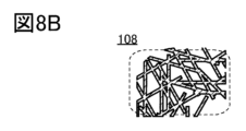
- Non-Patent Document 1 a compound obtained by reducing graphene oxide (GO) is sometimes called reduced GO (rGO), and its physical properties have attracted attention.
- GO graphene oxide
- rGO reduced GO
- Patent Document 1 describes that when the smartwatch is deformed by an external force, it is preferable that the secondary battery also has flexibility. was fixed to the smart watch along with the board.
- Patent Document 2 a lithium ion battery is mounted, it is fixed at a position overlapping a non-movable housing.
- an object of one embodiment of the present invention is to provide a flexible battery that can follow a movable housing.
- one embodiment of the present invention includes a negative electrode and a positive electrode, wherein the negative electrode includes a first material containing carbon, a first current collector, and a negative electrode active layer formed on the first current collector. wherein the first carbon-containing material envelops the first current collector and the negative electrode active material, and the positive electrode comprises the second carbon-containing material, the second current collector, and the second and a positive electrode active material formed on a current collector, wherein the second carbon-containing material encases the second current collector and the positive electrode active material.
- Another aspect of the present invention has a negative electrode and a positive electrode, wherein the negative electrode includes a first material containing carbon, a first current collector, and a second current collector located in an opening of the first current collector. and a negative electrode active material formed on the first current collector and the second current collector, and the first material containing carbon is the first current collector and the second current collector.
- the positive electrode comprising: a second carbon-containing material; a third current collector; and a fourth current collector located in an opening of the third current collector;
- a positive electrode active material formed on a third current collector and a fourth current collector, and the second carbon-containing material comprises the third current collector, the fourth current collector, and the positive electrode. It is a flexible battery that encloses an active material.
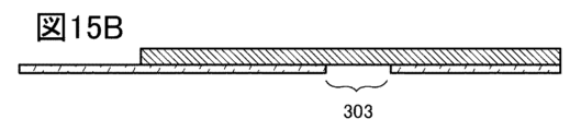
- the second current collector and the fourth current collector are provided so as to overlap the bending region.
- each of the first carbon-containing material and the second carbon-containing material preferably has a bag shape or a tubular shape.
- the first carbon-containing material and the second carbon-containing material preferably each have a graphene compound.
- the graphene compound is preferably graphene oxide.
- the graphene compound is preferably reduced graphene oxide.
- the first carbon-containing material and the second carbon-containing material each preferably comprise graphene.
- the first carbon-containing material and the second carbon-containing material each preferably have carbon fibers.
- Another embodiment of the present invention preferably has a separator between the negative electrode and the positive electrode.
- the separator preferably has a bag shape or a tubular shape.
- Another aspect of the present invention preferably does not have a separator positioned between the negative electrode and the positive electrode.
- the area of the positive electrode is preferably smaller than the area of the negative electrode.
- the median diameter (D50) of the negative electrode active material or the positive electrode active material is preferably 10 nm or more and 30 ⁇ m or less.
- the positive electrode active material preferably has secondary particles, and the median diameter (D50) of the primary particles constituting the secondary particles is preferably 10 nm or more and 1 ⁇ m or less.
- Another aspect of the present invention is an electronic device equipped with a flexible battery.
- An aspect of the present invention can provide a flexible battery that can follow a movable housing.
- 1A and 1B are cross-sectional views showing flexible batteries according to one embodiment of the present invention.
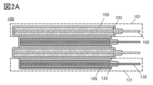
- 2A and 2B are cross-sectional views illustrating flexible batteries according to one embodiment of the present invention.
- 3A and 3B are cross-sectional views illustrating flexible batteries according to one embodiment of the present invention.
- 4A and 4B are a cross-sectional view and a top view of a negative electrode of one embodiment of the present invention.
- 5A to 5C are cross-sectional views illustrating a negative electrode active material layer and the like of one embodiment of the present invention.
- 6A and 6B are diagrams showing graphene compounds of one embodiment of the present invention.
- 7A and 7B are diagrams showing a spray drying apparatus.
- FIGS. 8A and 8B are cross-sectional views illustrating the active material layer and the like of the negative electrode of one embodiment of the present invention.
- 9A and 9B are a cross-sectional view and a top view of a positive electrode of one embodiment of the present invention.
- FIG. 10 is a cross-sectional view showing a negative electrode according to one embodiment of the present invention.
- FIG. 11 is a cross-sectional view showing a negative electrode according to one embodiment of the present invention.
- FIG. 12 is a cross-sectional view showing a negative electrode according to one embodiment of the present invention.
- FIG. 13 is a cross-sectional view showing a flexible battery of one form of the present invention.
- 14A to 14C are cross-sectional or top views of a flexible battery of one embodiment of the present invention.
- 15A to 15D are cross-sectional views illustrating the negative electrode of one embodiment of the present invention.
- 16A to 16D are cross-sectional views illustrating the negative electrode of one embodiment of the present invention.
- 17A to 17D are cross-sectional views illustrating the negative electrode of one embodiment of the present invention.
- 18A and 18B are cross-sectional views showing flexible batteries according to one embodiment of the present invention.
- 19A to 19E are cross-sectional views and the like showing an exterior body of one embodiment of the present invention.
- 20A to 20C are cross-sectional views and the like showing an exterior body of one embodiment of the present invention.
- 21A and 21B are cross-sectional views and the like showing an exterior body of one embodiment of the present invention.
- 22A to 22E are cross-sectional views and the like showing an exterior body of one embodiment of the present invention.
- 23A to 23E are cross-sectional views and the like showing an exterior body of one embodiment of the present invention.
- FIG. 24 is a cross-sectional view showing an exterior body of one embodiment of the present invention.
- 25A and 25B are top views showing an exterior body of one embodiment of the present invention.
- 26A to 26C are top views showing the exterior body of one embodiment of the present invention.
- 27A to 27E are top views, cross-sectional views, or the like illustrating a flexible battery of one embodiment of the present invention.
- 28A and 28B are cross-sectional views showing an exterior body of one embodiment of the present invention.
- 29 is a flow showing a method for manufacturing a positive electrode active material by a coprecipitation method of one embodiment of the present invention.
- 30A to 30C are flow charts showing a method for manufacturing a positive electrode active material by a solid-phase method of one embodiment of the present invention.
- 31A and 31B are diagrams illustrating an electronic device of one embodiment of the present invention.
- 32A and 32B are diagrams illustrating an electronic device of one embodiment of the present invention.
- 33A to 33D are diagrams illustrating an electronic device of one embodiment of the present invention.
- 34A to 34D are diagrams illustrating an electronic device of one embodiment of the present invention.
- 35A to 35C are diagrams illustrating electronic devices of one embodiment of the present invention.
- 36A to 36C are diagrams illustrating electronic devices of one embodiment of the present invention.
- a flexible battery is a battery with mobility, and specifically refers to a battery that can follow a movable housing while being sandwiched between the housings.
- a flexible battery 100 of one embodiment of the present invention will be described.
- the flexible battery 100 is a battery that can follow when the housing in which it is mounted moves, and for example, a lithium ion battery (lithium ion secondary battery) can be used as the battery.
- Flexible battery 100 of one embodiment of the present invention can also be in a bent state.
- the cross-sectional view shown in FIG. 1A shows flexible battery 100 in a straightened state.
- the cross-sectional view shown in FIG. 1B shows a state in which flexible battery 100 is bent.
- the flexible battery 100 of one aspect of the present invention can alternate between the straight state shown in FIG. 1A and the bent state shown in FIG. 1B.
- the flexible battery 100 shown in FIG. 1B When the flexible battery 100 shown in FIG. 1B is in a bent state, it has a curved portion, so it may be referred to as a battery having a curved portion.
- the bending position can be positioned at the central portion of flexible battery 100, the bending position can be positioned at a position other than the central portion.
- the flexible battery 100 has a negative electrode 101 and a positive electrode 131, and has a structure in which the negative electrode 101 and the positive electrode 131 are laminated (sometimes referred to as a laminated structure or a laminated electrode).
- the number of layers of negative electrodes 101 and the number of layers of positive electrodes 131 may be equal, but the number of layers of negative electrodes 101 may differ from the number of layers of positive electrodes 131 .
- the number of laminated layers of the negative electrode 101 may be larger than the number of laminated layers of the positive electrode 131 .
- FIG. 1A shows the case where the area of the negative electrode 101 and the area of the positive electrode 131 are equal.
- the area of the negative electrode 101 and the area of the positive electrode 131 may be the same, but the area of the negative electrode 101 may be different from the area of the positive electrode 131 .
- FIG. 2A shows a configuration in which the area of the negative electrode 101 is larger than the area of the positive electrode 131 .
- FIG. 2B shows a configuration in which the area of the negative electrode 101 is larger than that of the positive electrode 131, and one end of the negative electrode 101 and the positive electrode 131 are aligned. That is, in the flexible battery 100 of one embodiment of the present invention, one ends of the negative electrode 101 and the positive electrode 131 may be aligned or may not be aligned. However, the current collector protruding from the one end is welded between the negative electrodes 101 and further welded between the positive electrodes 131 . 2A and 2B, when the area of the negative electrode 101 is larger than the area of the positive electrode 131, it is possible to reduce the area of the positive electrode 131 that does not face the negative electrode 101 when the flexible battery 100 is bent. .
- Flexible battery 100 of one aspect of the present invention has carbon-containing material 105 positioned at least between adjacent negative electrode 101 and positive electrode 131 to reduce friction between adjacent negative electrode 101 and positive electrode 131.
- the flexible battery 100 of one embodiment of the present invention has a structure in which the active material layer of the negative electrode 101 or the active material layer of the positive electrode 131 is wrapped with the material 105 containing carbon. By wrapping one of the active material layers with the material 105 containing carbon, friction between the negative electrode 101 and the positive electrode 131 can be reduced.
- the flexible battery 100 of one embodiment of the present invention preferably has a structure in which the active material layers of the negative electrode 101 and the positive electrode 131 are wrapped in the material 105 containing carbon.
- flexible battery 100 with carbon-containing material 105 can form a good electronic conduction path with at least an amount of conductive material.
- a graphene compound, graphene, or carbon fiber can be used for the material 105 containing carbon, and even if the graphene compound, graphene, or carbon fiber is attached to the active material layer, the above-described friction during movement can be suppressed. can be done.
- Graphene compounds and the like will be described later.
- the material 105 containing carbon can exhibit electrical conductivity if it is, for example, a carbon material, and can also exhibit insulating properties depending on the ratio of oxygen or the like contained therein.
- the negative electrode 101 includes a current collector 102 (sometimes referred to as a negative electrode current collector) and an active material layer 103 (sometimes referred to as a negative electrode active material layer).
- the positive electrode 131 includes a current collector 132 (sometimes referred to as a positive electrode current collector) and an active material layer 133 (sometimes referred to as a positive electrode active material layer). An ordinal number is sometimes given to distinguish the current collectors from each other.
- the carbon-containing material 105 may be a flexible battery 100 with a separator.
- FIG. 3A shows a flexible battery 100 having a separator 134 unlike FIGS. 1A-2B.
- Separator 134 preferably has a bag-like or tubular shape, and FIG. When the separator 134 has a bag shape or a tubular shape, the positive electrode 131 does not protrude from the separator 134, and a flexible battery with high safety and durability can be provided.
- FIG. 3A shows the case where the positive electrode 131 has a smaller area than the negative electrode 101 as in FIG. 2A or 2B. and Of course, the negative electrode 101 may be housed in the separator 134 .
- FIG. 3B shows a flexible battery 100 having a sheet-like separator 109 unlike FIG. 3A.
- a flexible battery with high safety or reliability can be provided.
- the flexible battery 100 with a separator may be provided.
- the material 105 containing carbon when the material 105 containing carbon exhibits insulating properties, the material 105 containing carbon can function as a separator, so that the flexible battery 100 can eliminate the need for a separator, which is preferable.
- FIG. 4A shows a cross-sectional view of the negative electrode 101
- FIG. 4B shows a top view of the negative electrode 101.
- the cross-sectional view of FIG. 4A corresponds to the cross-section at the position indicated by the dotted line in FIG. 4B.
- a negative electrode 101 has a current collector 102 and an active material layer 103 .
- the active material layer 103 is preferably formed on two surfaces (one surface and the other surface) of the current collector 102 . Forming the active material layer 103 on two sides is referred to as a double-sided formation structure or a double-sided coating structure.
- the active material layer 103 may be formed on either one side or the other side of the current collector 102 . Forming the active material layer 103 on one side is referred to as a single-sided formation structure or a single-sided coating structure.
- the current collector 102 and the active material layer 103 are covered with a material 105 containing carbon.
- the material 105 containing carbon surrounds the current collector 102 and the active material layer 103 .
- the flexible battery 100 of one embodiment of the present invention absorbs carbon when repeating the straight state shown in FIGS. 1A, 2A to 3B, and the like and the bent state shown in FIG. Since the included material 105 serves as a so-called cushioning material that reduces friction, the flexible battery 100 can be easily moved and has high safety or durability.
- the material 105 containing such carbon is sometimes referred to as a buffer layer or a buffer film.
- the material 105 containing carbon preferably has characteristics of being flexible and easily deformable. Further, it is expected that the mechanical strength of the electrode or the like provided with the material 105 containing carbon is increased.
- a graphene compound, graphene, or carbon fiber can be used for the material 105 containing carbon. can be suppressed.
- the material 105 containing carbon may be attached only to the active material layer, but it is preferably arranged on the negative electrode 101 in the form of a layer or a film in order to further reduce friction between the adjacent negative and positive electrodes.
- a layered carbon-containing material may be referred to as a carbon-containing material layer, and a film-like carbon-containing material may be referred to as a carbon-containing material film.
- the material layer containing carbon or the material film containing carbon is preferably as thin as possible because the active material per unit volume can be increased, and the upper limit of the thickness is 100 ⁇ m or less, preferably 10 ⁇ m or less. If the material layer containing carbon and the material film containing carbon are to be distinguished from each other, the material film containing carbon can have a maximum thickness of 1 ⁇ m or less.
- FIG. 5A shows the details of the negative electrode 101, specifically the active material layer 103 and the like.
- the active material layer 103 includes an active material 104 (sometimes referred to as a negative electrode active material), a first conductive material 107a, and a second conductive material 107b. Although an example using two conductive materials is shown in this embodiment, one conductive material may be used, or three or more conductive materials may be used.
- the negative electrode 101 has a current collector 102, and the current collector 102 also has a region in which an active material 104 is embedded.
- FIG. 5B shows an enlarged view of the active material layer 103.
- Active material layer 103 has active material 104 .
- the material of the active material 104 will be described later, it may be either primary particles or secondary particles.
- the active material ratio per volume can be increased by pressing or the like.
- the first conductive material 107a and the second conductive material 107b are preferably dispersed inside the active material layer 103, and preferably dispersed evenly.
- the second conductive material 107b is fine particles and may have lower dispersibility than the first conductive material 107a.
- the first conductive material 107a is schematically represented by a thick line. It is preferable because it can be positioned so as to stick to it.
- the plurality of first conductive members 107a can also be in surface contact with each other.
- the first conductive materials 107 a that are in surface contact with each other may be positioned so as to wrap or cover the plurality of active materials 104 or stick to the surfaces of the active materials 104 .
- a graphene compound, graphene, or carbon fiber can be used for the first conductive material 107a.
- the graphene compound will be described later, since it is used as a conductive material, a material exhibiting conductivity is used.
- the graphene compound has a thickness of a single layer or multiple layers of carbon molecules, it is often formed into a very thin film and can be attached to the surface of the active material 104 .
- Graphene is thin because it has the thickness of multiple layers of carbon molecules, but it can also have a rectangular shape.
- Carbon fibers may be shaped such that the fibers are entangled with each other. Note that even graphene and carbon fiber can be positioned so as to be in contact with the surface of the active material 104 by pressing.
- the graphene compound used for the first conductive material 107a is in a state in which graphene compounds are bonded to each other, and this is sometimes referred to as a graphene compound sheet or a graphene compound net.
- Graphene compounds may be arranged in a network depending on how they bond to each other, and may be referred to as a network graphene compound sheet or a network graphene compound net. Such a graphene compound sheet may be used for the first conductive material 107a.
- the graphene compound sheet When a graphene compound sheet is used as the first conductive material 107a, the graphene compound sheet can cover the active material 104 and can also function as a binder. When the function as a binder is exhibited, the amount of the binder in the negative electrode 101 can be reduced or the binder can be eliminated, so that the active material ratio per volume in the negative electrode 101 can be increased.
- FIG. 5C shows an enlarged view of the material 105 containing carbon, and illustrates a case where a graphene compound sheet is used as the material 105 containing carbon.
- the graphene compound sheet is as described for the first conductive material 107a, and may have a plurality of planar graphene compounds 120 as shown in FIG. 5C in an enlarged view. Although the graphene compound 120 is used, the graphene compound sheet may have graphene.
- the length of one side of the graphene compound (also referred to as flake size) is 50 nm or more and 100 ⁇ m or less, preferably 800 nm or more and 20 ⁇ m or less. Therefore, a region 121 through which ions can pass exists between adjacent graphene compounds.
- a graphene compound sheet has excellent ion conductivity and is preferable as the material 105 containing carbon. In such a graphene compound sheet, an electrolyte, specifically an electrolytic solution, can penetrate into the graphene compound sheet through the region 121 or the like through which ions can pass.
- the graphene compound sheet can be provided along the surface of the active material layer 103 as a material 105 containing carbon as shown in FIG. 5A. Specifically, the graphene compound sheet can be provided as the material 105 containing carbon so as to continuously cover part of the surfaces of the plurality of active materials 104 . Such a state may be described as the material 105 containing carbon enveloping the active material layer or the active material.
- FIG. 5C illustrates the case of a graphene compound sheet
- a graphene sheet or a graphene net in which graphenes are bonded to each other may be used.
- the length of one side of graphene (also referred to as flake size) is 50 nm or more and 100 ⁇ m or less, preferably 800 nm or more and 20 ⁇ m or less. sell.
- Such a graphene sheet has excellent ion conductivity and is preferable as the material 105 containing carbon.
- a graphene sheet or a graphene net may be referred to as multilayer graphene based on a cross-sectional view.
- the active material 104 a material capable of undergoing charge/discharge reaction by insertion and extraction of carrier ions is used.
- Lithium ions are preferably used as carrier ions.
- sodium ions, potassium ions, calcium ions, strontium ions, barium ions, beryllium ions, magnesium ions, or the like may be used.
- a specific example of the active material when lithium ions are used will be described later.
- a granular material can be used as the active material 104 .
- Granular is a term that indicates an external shape having any surface area including, for example, spherical (powder), plate-like, angular, columnar, needle-like, or scaly-like shapes. That is, the granular active material does not necessarily mean a spherical shape, but includes the various external shapes described above.
- the active material layer 103 has a plurality of active materials 104, they may have different shapes.
- the median diameter (D50) is often used. is preferred. A small median diameter (D50) is preferable because the negative electrode 101 can be easily bent as shown in FIG. 1B.
- the median diameter (D50) of the primary particles constituting the secondary particles is, for example, 10 nm or more and 1 ⁇ m or less, preferably 100 nm or more and 500 m or less.
- a small median diameter (D50) is preferable because the negative electrode 101 can be easily bent as shown in FIG. 1B.
- the carbon-containing material 105 envelops the active material layer 103 so that the carbon-containing material 105 conforms to the shape of the active material 104 located on the surface of the active material layer 103.
- the material 105 containing carbon has high flexibility, it can be provided along the shape of the active material 104 .
- the active material 104 may collapse from the current collector 102 due to repeated charging and discharging. Also, the active material 104 may collapse from the current collector 102 when the battery operates.
- the material 105 containing carbon is positioned so as to wrap the current collector 102 and the active material layer 103; Collapse from 102 can be suppressed. When the material 105 containing carbon has a region in contact with the current collector 102, the force of suppressing the active material 104 may be increased.
- a material 105 containing bag-like carbon In order to efficiently wrap the current collector 102 and the active material layer 103, it is preferable to prepare a material 105 containing bag-like carbon.
- a material 105 containing bag-like carbon When the negative electrode 101 or the like is bent as shown in FIG. 1B, the current collector 102 and the active material layer 103 are unlikely to protrude from the side or bottom of the bag-shaped carbon-containing material 105, so safety or durability is improved. can be enhanced.
- a cylindrical material 105 containing carbon instead of the bag-like shape, a cylindrical material 105 containing carbon may be prepared. Even in the cylindrical material 105 containing carbon, when the negative electrode 101 or the like is bent as shown in FIG. Therefore, safety or durability can be enhanced.
- the active material layer 103 preferably contains an electrolyte.
- An electrolyte that is liquid at room temperature (25° C.) is also referred to as an electrolytic solution.
- the carbon-containing material 105 can be impregnated with electrolyte.
- the electrolyte can also penetrate between the graphene compounds 120 .
- the active material layer 103 may have a binder. Further, since the active material layer can be wrapped with the material 105 containing carbon, a binder can be eliminated.
- graphene is one atomic layer of carbon arranged and has a ⁇ bond between carbon atoms. That is, graphene includes carbon, has a shape such as a sheet shape (also referred to as a plate shape), and has a two-dimensional structure formed of six-membered carbon rings. The two-dimensional structure formed by the six-membered carbon rings may be called a carbon sheet.
- graphene in which two to 100 layers are stacked is sometimes called multilayer graphene.
- Graphene and multi-layer graphene have, for example, a length of 50 nm or more and 100 ⁇ m or less or a length of 800 nm or more and 50 ⁇ m or less of the major axis in the longitudinal direction or in the plane.
- graphene compounds are described.
- a compound having graphene or multilayer graphene as a basic skeleton is called a “graphene compound” (also referred to as “graphene compound”).
- Other graphene compounds include graphene oxide, multilayer graphene oxide, reduced graphene oxide, reduced multilayer graphene oxide, graphene quantum dots, and the like, which will be described later.
- a graphene compound is, for example, a compound in which graphene or multilayer graphene is modified with an atom other than carbon or an atomic group having an atom other than carbon.
- graphene or multilayer graphene may be a compound modified with an atomic group mainly composed of carbon such as an alkyl group or an alkylene group. Note that an atomic group that modifies graphene or multilayer graphene is sometimes referred to as a substituent, a functional group, a characteristic group, or the like.
- modification refers to an atomic group having an atom other than carbon, or an atom other than carbon to graphene, multilayer graphene, graphene compound, or graphene oxide (described later) by substitution reaction, addition reaction, or other reaction.
- substitution reaction addition reaction, or other reaction.
- a graphene compound is, for example, one that contains carbon, has a shape such as a sheet shape, and has a two-dimensional structure formed of six-membered carbon rings.
- the two-dimensional structure formed by the six-membered carbon rings may be called a carbon sheet.
- graphene oxide examples include graphene or multilayer graphene modified with oxygen or oxygen-containing functional groups.
- oxygen-containing functional group include an epoxy group, a carbonyl group such as a carboxyl group, a hydroxyl group, a lactol group, and the like.
- a graphene compound modified with oxygen or a functional group containing oxygen is sometimes called graphene oxide.
- graphene oxide also includes multi-layered graphene oxide. Graphene oxide can exhibit insulating properties.
- ⁇ Terminated with fluorine> As the graphene compound, a material obtained by terminating graphene with fluorine may be used.
- Graphene oxide can be obtained by oxidizing the above graphene or multilayer graphene.
- graphene oxide can be obtained by separating the layers of graphite oxide.
- Graphite oxide can be obtained by oxidizing graphite.
- graphene oxide may be further modified with the above atoms or atomic groups.
- Methods for producing graphene oxide include various synthesis methods such as Hummers method, modified Hummers method, and oxidation of graphite.
- the Hummers method and the modified Hummers method are methods of forming graphite oxide by oxidizing graphite such as flake graphite.
- the formed graphite oxide is a mixture of carbonyl, carboxy, hydroxyl, lactol, and other functional groups that are formed by oxidizing graphite in places, impairing the crystallinity of graphite and increasing the distance between layers. It's becoming Therefore, graphene oxide can be obtained by separating the layers easily by ultrasonic treatment or the like.
- a solution of potassium permanganate in sulfuric acid or the like is added to the graphite powder for an oxidation reaction to form a mixed solution containing graphite oxide.
- Graphite oxide has functional groups such as an epoxy group, a carbonyl group, a carboxy group, and a hydroxyl group due to oxidation of graphite carbon. Therefore, the interlayer distance of graphene oxide is longer than that of graphite.
- the graphite oxide having a long interlayer distance can be cleaved to separate graphene oxide, and a dispersion containing graphene oxide can be formed. .
- the obtained graphene oxide may contain elements such as sulfur and nitrogen, for example.
- the concentration of sulfur in the graphene compound of one embodiment of the present invention is preferably 5% or less, more preferably 3% or less.
- the graphene compound of one embodiment of the present invention may have, for example, 10 ppm or more and 5% or less, or 100 ppm or more and 3% or less, or 0.1% or more and 3% or less of sulfur.
- the concentration of sulfur contained in the graphene compound can be evaluated using, for example, elemental analysis such as XPS.
- the graphene compound of one embodiment of the present invention may contain, for example, 0.1% or more and 3% or less of nitrogen.
- RGO Reduced Graphene Oxide
- RGO may be written as "rGO” as shown in Non-Patent Document 1. Note that in RGO, all of the oxygen contained in graphene oxide is not eliminated and part of oxygen or an atomic group containing oxygen remains in a state of being bonded to carbon in some cases.
- RGO may have functional groups such as epoxy groups, carbonyl groups such as carboxyl groups, or hydroxyl groups.
- the reduced graphene oxide preferably has a portion where the carbon concentration is higher than 80 atomic % and the oxygen concentration is higher than or equal to 2 atomic % and lower than or equal to 15 atomic %. With such carbon concentration and oxygen concentration, the conductivity of the reduced graphene oxide can be increased.
- the reduced graphene oxide preferably has an intensity ratio G/D of 1 or more between the G band and the D band in a Raman spectrum. Reduced graphene oxide with such an intensity ratio can be highly conductive.
- graphene oxide may be reduced by heat treatment or by using a reducing agent, for example.
- Reduced graphene oxide includes, for example, carbon and oxygen, has a shape such as a sheet, and has a two-dimensional structure formed of six-membered carbon rings.
- pores can be provided in the graphene compound in some cases.
- the pores of the graphene compound can correspond to regions through which carrier ions, specifically lithium ions, can pass. With such holes, carrier ions can be easily inserted and detached, and the rate characteristics of the battery can be improved. Pores provided in a portion of the carbon sheet are sometimes referred to as voids, defects or voids.
- carrier ions it is preferable that ions of alkali metals other than lithium, anions and cations used in the electrolyte, and anions and cations contained in the electrolyte can pass through.
- the graphene compound may have pores provided by a plurality of carbon atoms and one or more fluorine atoms.
- the plurality of carbon atoms are preferably cyclically bonded, and one or more of the plurality of cyclically bonded carbon atoms are preferably terminated with the fluorine.
- Fluorine has high electronegativity and tends to be negatively charged. The proximity of the positively charged lithium ions causes interaction, stabilizes the energy, and lowers the barrier energy for carrier ions, specifically lithium ions, to pass through the pores. Therefore, since the pores of the graphene compound contain fluorine, carrier ions can easily pass through even small pores and the graphene compound can have excellent conductivity.
- the graphene compound may have a five-membered ring made of carbon, or a multi-membered ring of seven or more members made of carbon, in addition to the six-membered ring made of carbon.
- a region through which ions can pass may occur in the vicinity of the multi-membered ring of seven or more.
- a region through which ions can pass can be regarded as the hole.
- ions include carrier ions, specifically lithium ions.
- examples of the ions described above include ions of alkali metals other than lithium, anions possessed by the electrolyte, cations, and the like.
- 6A and 6B show an example of the structure of a graphene compound having pores.
- the configuration shown in FIG. 6A has a 22-membered ring, with each of the 8 carbons making up the 22-membered ring terminated by a hydrogen. It can also be said that the graphene compound has a structure in which two connected 6-membered rings are removed and the carbons bonded to the removed 6-membered rings are terminated with hydrogen.
- the configuration shown in FIG. 6B has a 22-membered ring with 8 carbons of the carbons making up the 22-membered ring terminated by hydrogen on 6 carbons and fluorine on 2 carbons. It can also be said that the graphene compound has a structure in which two connected 6-membered rings are removed and the carbons bonded to the removed 6-membered rings are terminated with hydrogen or fluorine.
- mapping measurement of Raman spectroscopy may allow observation of a spectrum based on features caused by the pores.
- bonds, functional groups, and the like that constitute pores can be observed by time-of-flight secondary ion mass spectrometry (ToF-SIMS).
- TEM transmission electron microscope observation may enable analysis of the vicinity of the hole, the periphery of the hole, and the like.
- the graphene compound may be in the form of a single sheet in which a plurality of graphene compounds are partially overlapped. Alternatively, a plurality of graphene compounds may be gathered to form a sheet shape. Since the graphene compound has a planar shape, surface contact is possible. Such a graphene compound may be referred to as a graphene compound sheet or a graphene compound net as described above.
- the graphene compound sheet has, for example, a region with a thickness of 0.33 nm or more and 100 ⁇ m or less, more preferably 0.34 nm or more and 10 ⁇ m or less.
- a graphene compound sheet may have an ion-passable region, for example, between adjacent graphene compounds. Therefore, the graphene compound sheet may have excellent ion conductivity. Alternatively, the graphene compound sheet may easily adsorb ions. Again, examples of ions include carrier ions, specifically lithium ions. Further, examples of the ions described above include ions of alkali metals other than lithium, anions possessed by the electrolyte, cations, and the like.
- the graphene compound sheet can be deformed when an external force is applied due to the slipping of the graphene compounds that overlap each other in a plane, and cracks and the like are unlikely to occur in some cases.
- Such a graphene compound sheet may be modified with an atom other than carbon, an atomic group having an atom other than carbon, or an atomic group mainly composed of carbon such as an alkyl group. Further, each of the plurality of layers of the graphene compound sheet may be modified with different atoms or atomic groups.
- Graphene compounds may have high conductivity even if they are thin, and surface contact can increase the contact area between graphene compounds or between the graphene compounds and an active material. Therefore, even if the amount per volume is small, the conductive path can be efficiently formed.
- a graphene compound can also be used as an insulator.
- a graphene compound sheet can be used as a sheet-like insulator.
- graphene oxide may have higher insulating properties than a non-oxidized graphene compound.
- the graphene compound modified with an atomic group can have improved insulating properties depending on the type of the modified atomic group.
- a graphene compound can be manufactured using a spray drying method, a coating method, or the like.
- a graphene oxide dispersion is used as a raw material and a graphene compound sheet is manufactured by a spray drying method will be described.
- the graphene oxide contained in the graphene oxide dispersion may be multi-layered graphene oxide, and the graphene oxide dispersion may contain graphene oxide or graphene oxide and multi-layered graphene oxide.
- a polar solvent is preferably used as the solvent for the graphene oxide dispersion.
- Polar solvents selected from, for example, water, methanol, ethanol, acetone, tetrahydrofuran (THF), dimethylformamide (DMF), 1-methyl-2-pyrrolidone (NMP) and dimethylsulfoxide (DMSO), ethylene glycol, diethylene glycol, and glycerin.
- THF tetrahydrofuran
- DMF dimethylformamide
- NMP 1-methyl-2-pyrrolidone
- DMSO dimethylsulfoxide
- a graphene compound including graphene oxide can be obtained by forming a plurality of graphene oxide films over a substrate or a plate by a spray drying method. When a plurality of graphene compounds overlap each other during film formation, a graphene compound sheet can be produced.
- the film thickness of the graphene compound or the graphene compound sheet can be controlled by adjusting the film formation time, the concentration of the dispersion liquid, or the like. Suitable for fabrication.
- the graphene compound or graphene compound sheet can be peeled off from the substrate or plate. Further, the substrate or plate can be replaced with the active material layer in FIGS. 1 to 5 and the like, and a graphene compound or a graphene compound sheet can be formed over the active material layer. In this case, the graphene compound or graphene compound sheet does not have to be peeled off.
- FIG. 7A shows a schematic diagram of a spray drying apparatus 280.
- Spray drying apparatus 280 has chamber 281 and nozzle 282 .
- a pump (not shown) draws up the dispersion liquid 284 and supplies the dispersion liquid 284 to the nozzle 282 through the tube 283 .
- a spray dispersion 284 is supplied to the chamber 281 and the dispersion 284 dries within the chamber 281 .
- Spray drying apparatus 280 may have heater 285 to heat nozzle 282 .
- Heater 285 may also heat a region of chamber 281 near nozzle 282, such as region 290 shown in dashed lines in FIG. 7A.
- the graphene oxide supplied from the graphene oxide dispersion becomes the graphene compound or the graphene compound sheet 222 and is deposited on the wall surface of the chamber 281 .
- part of the graphene oxide supplied from the graphene oxide dispersion is dried in the chamber 281 to be powdered and collected from the chamber 281 into the collection container 286 .
- a nozzle (not shown) may be connected to the collection container 286 and the graphene oxide may be collected through the nozzle. The collected graphene oxide can be reused as a graphene oxide dispersion.
- the atmosphere in the chamber 281 may be adjusted, and the inside of the chamber 281 may be sucked by an aspirator or the like along the path indicated by the arrow 288 in FIG. 7A, for example.
- a nozzle (not shown) may be connected to the collection container 286 and the graphene oxide may be collected through the nozzle.
- a substrate or plate may be placed in the chamber 281, and a graphene compound or a graphene compound sheet may be formed thereon.
- the substrate or plate may be flat or curved. Further, the substrate or plate can be replaced with the active material layer in FIGS. 1 to 5 and the like, and a graphene compound or a graphene compound sheet can be formed over the active material layer having an uneven surface.
- the substrate or plate may be placed parallel to nozzle 282 or may be placed at an angle.
- a spray may be used instead of the nozzle 282 .
- it may be installed perpendicular to the nozzle 282 .
- FIG. 7B shows an example in which a substrate 287 is placed perpendicular to the nozzle 282 and a graphene compound or a graphene compound sheet is formed on the substrate.
- the nozzle 282 may be moved left and right as indicated by arrows to form a film, which can improve the uniformity of film thickness in the plane of the graphene compound or the graphene compound sheet.
- the substrate 287 may be moved left and right as indicated by the arrows. Furthermore, in order to improve the film thickness uniformity within the plane of the graphene compound or graphene compound sheet, both the nozzle 282 and the substrate 287 may be moved left and right as indicated by arrows.
- the interlayer distance of a graphene compound or a graphene compound sheet is shown.
- the interlayer distance of the graphene compound or graphene compound sheet is, for example, 0.335 nm or more and 0.7 nm or less, or more than 0.34 nm and 0.6 nm or less, or more than 0.34 nm and 0.5 nm or less, or more than 0.34 nm and 0 .44 nm or less.
- carrier ions can move between the layers.
- Methods for calculating the interlayer distance include TEM observation, evaluation using X-ray diffraction (XRD), and the like.
- TEM observation observation of a minute range, for example, observation of a range of several nanometers to several micrometers square is performed.
- evaluation using XRD may be able to evaluate a wider range of average information.
- the graphene compound or graphene compound sheet produced in this manner can exhibit insulating properties.
- reduction treatment is preferably performed.
- the graphene oxide is reduced, and the conductivity of the graphene compound or the graphene compound sheet can be increased.
- methods of reduction treatment include reduction by heat treatment, reduction using a reducing agent (this is sometimes referred to as chemical reduction), and the like.
- the reduction temperature of the chemical reduction is, for example, room temperature or higher and 100° C. or lower, preferably 40° C. or higher and 70° C. or lower.
- the treatment time for chemical reduction is 3 minutes or more and 10 hours or less, preferably 30 minutes or more and 3 hours or less.
- ascorbic acid, hydrazine, dimethylhydrazine, hydroquinone, sodium borohydride ( NaBH4 ), lithium aluminum hydride ( LiAlH4 ), or N,N-diethylhydroxylamine or derivatives thereof can be used.
- NaBH4 sodium borohydride
- LiAlH4 lithium aluminum hydride
- N,N-diethylhydroxylamine or derivatives thereof can be used.
- ascorbic acid and hydroquinone have weaker reducing power than hydrazine or sodium borohydride, so they are highly safe and easy to use industrially.
- the polar solvent is not particularly limited as long as it can dissolve the reducing agent.
- the graphene oxide dispersion may contain a reducing agent. That is, the graphene oxide dispersion may contain a reducing liquid containing a solvent and a reducing agent instead of the solvent.
- a reducing liquid containing a solvent and a reducing agent instead of the solvent.
- a mixture of ethanol and ascorbic acid, or a mixture of water, ascorbic acid and lithium hydroxide can be used as the reducing liquid.
- the graphene oxide may be protonated by ascorbic acid, for example, and H 2 O may be eliminated by subsequent heat treatment or the like, so that the graphene oxide can be reduced.
- washing may be performed. Washing may be carried out, for example, using the solutions mentioned as solvents. Note that cleaning may be performed using a solution containing the same solvent as the solvent contained in the reducing liquid, or cleaning using a solution containing a solvent different from the solvent contained in the reducing liquid. Moreover, you may perform a drying process after washing.
- the thermal reduction step may be performed, for example, at a temperature of 50° C. or more and less than 500° C., preferably 120° C. or more and 400° C. or less, for 1 hour or more and 48 hours or less, preferably 2 hours or more and 20 hours or less.
- Thermal reduction may be carried out under reduced pressure (vacuum) or in a reducing atmosphere, or may be carried out at atmospheric pressure.
- air may be used, or nitrogen or other inert gas may be used.
- the graphene compound or graphene compound sheet thus produced can exhibit electrical conductivity.
- FIG. 8A shows a negative electrode 101 having carbon fibers 108 as the carbon-containing material 105 shown in FIG. 5A and the like.
- An enlarged view of the carbon fiber 108 is shown in FIG. 8B. Since other configurations are the same as those in FIG. 5A and the like, description thereof is omitted.
- the carbon fiber 108 can have characteristics of being flexible and easily deformable, and can increase the mechanical strength of the negative electrode and the like.
- a fibrous material having a specific surface area of 5 m 2 /g or more and less than 60 m 2 /g is preferably used as the carbon fibers 108 .
- Carbon fibers such as mesophase pitch-based carbon fibers and isotropic pitch-based carbon fibers can be used as the carbon fibers 108 .
- Carbon nanofibers, carbon nanotubes, or the like can be used as the carbon fibers 108 .
- Carbon nanofibers or carbon nanotubes can be produced, for example, by vapor deposition.
- the carbon fibers 108 are preferably provided along the shape of the active material 104 located on the surface of the active material layer 103, as shown in FIG. 8A. Since the carbon fiber 108 has high flexibility, it can be provided along the shape of the active material 104 .
- the active material 104 may collapse from the current collector 102 due to repeated charging and discharging. Also, the active material 104 may collapse from the current collector 102 when the battery operates.
- the carbon fibers 108 are positioned so as to wrap the current collector 102 and the active material layer 103; You can prevent it from collapsing. Since the carbon fiber 108 has a region in contact with the current collector 102 , the force of suppressing the active material 104 may be increased.
- the active material layer 103 has a binder and an electrolyte.
- a liquid electrolyte is also referred to as an electrolytic solution.
- the carbon fibers 108 can be impregnated with an electrolytic solution, and are preferably dispersed so that carrier ions can pass through them.
- the material 105 containing carbon shown in FIG. 5A and the like and the carbon fibers 108 shown in FIG. 8 and the like preferably have conductivity.
- Graphene or the like can be selected as the conductive carbon-containing material 105 .
- the material 105 containing carbon shown in FIG. 5 and the like preferably has insulating properties.
- the conductive material 105 containing carbon graphene oxide, reduced graphene oxide, or the like can be selected.
- the carbon-containing material 105 preferably has an insulating property to the extent that short-circuiting between the positive electrode and the negative electrode can be prevented, in which case a separator can be eliminated.
- the insulating carbon-containing material 105 can be selected from materials described later, and a material with a high oxygen content is preferable.
- the carbon-containing material 105 shown in FIG. 5 and the like and the carbon fiber 108 shown in FIG. 8 and the like may be mixed with the polymer material. Insulative properties can be exhibited by the proportion of polymer material. Polypropylene (PP), polyethylene (PE), polybutene, nylon, polyester, polysulfone, polyacrylonitrile, polyvinylidene fluoride, tetrafluoroethylene, or the like can be used as the polymer material. A polymer material is preferable because it does not impair the flexibility of the carbon-containing material 105 and the carbon fiber 108 and has insulating properties.
- FIGS. 9A and 9B show details of the positive electrode 131.
- 9A shows a cross-sectional view of the positive electrode 131
- FIG. 9B shows a top view of the positive electrode 131.
- the cross-sectional view of FIG. 9A corresponds to the cross-section at the position indicated by the dotted line in FIG. 9B.
- a positive electrode 131 has a current collector 132 and an active material layer 133 .
- the active material layer 133 is preferably formed on two surfaces (one surface and the other surface) of the current collector 132 .
- forming the active material layer 133 on two sides is referred to as a double-sided formation structure or a double-sided coating structure.
- the active material layer 133 may be formed on either one side or the other side of the current collector 132 .
- forming the active material layer 133 on one surface is referred to as a single-sided formation structure or a single-sided coating structure.
- the flexible battery 100 of one embodiment of the present invention serves as a so-called cushioning material in which the carbon-containing material 105 reduces friction when the states of FIGS. 1A and 1B are repeated. Therefore, it becomes easier to move.
- the material 105 containing carbon can be flexible and deformable, and can increase the mechanical strength of the positive electrode and the like.
- the positive electrode 131 also has an active material, a conductive material, a binder, an electrolytic solution, and the like.
- carbon fibers 108 may be used in place of the carbon-containing material 105 in the positive electrode 131 as in the configuration shown in FIG.
- the carbon fiber 108 can be flexible and easily deformable, and can increase the mechanical strength of the positive electrode and the like.
- Configuration example 2 As configuration example 2, a flexible battery 200 in which the active material layer has a single-sided forming structure or a single-sided coating structure and a carbon-containing material is provided between overlapping current collectors, unlike configuration example 1 described above, will be described.
- the cross-sectional view shown in FIG. 10 shows the flexible battery 200 in a straight state, and the flexible battery 200 of one aspect of the present invention can alternate between the straight state shown in FIG. 10 and the bent state.
- the negative electrode 201 has a current collector 102 and an active material layer 103, like the negative electrode 101 of Structural Example 1 described above.
- the active material layer 103 is formed on one surface of the current collector 102 because it has a single-sided formation structure or a single-sided coating structure.
- Another current collector 102 and another active material layer 103 are prepared, and a material 105 containing carbon is provided between the two stacked current collectors 102 .
- Such a negative electrode 201 is prepared.
- the positive electrode 231 has a current collector 132 and an active material layer 133, like the positive electrode 131 of Configuration Example 1 described above.
- the active material layer 133 is formed on one surface of the current collector 132 because it has a single-sided formation structure or a single-sided coating structure.
- Another current collector 132 and another active material layer 133 are prepared, and the material 105 containing carbon is provided between the two stacked current collectors 132 .
- Such a positive electrode 231 is prepared.
- a separator 221 is arranged between the negative electrode 201 and the positive electrode 231 .
- the material 105 containing carbon is positioned between two current collectors.
- the flexible battery 200 of one embodiment of the present invention is a so-called buffer material in which the material 105 containing carbon reduces friction when the state in FIG. 10 and the bent state are repeated. Therefore, it becomes easier to move. That is, the material 105 containing carbon is sometimes referred to as a buffer layer.
- the material 105 containing carbon positioned between the two current collectors may exhibit insulating properties, but preferably exhibits conductivity.
- FIG. 11 shows the details of the negative electrode 201, specifically the active material layer 103 and the like.
- the active material layer 103 in FIG. 11 is similar to the active material layer 103 and the like shown in FIG.
- the active material layer 103 may have a binder and an electrolyte as in FIG. 5, and the electrolyte may be an electrolytic solution.
- the carbon-containing material 105 positioned between the two current collectors 102 may not be impregnated with an electrolytic solution and may not have pores through which carrier ions can pass.
- FIG. 12 shows a negative electrode 101 having a carbon fiber 108 instead of the carbon-containing material 105 shown in FIG. 11 and the like. Since other configurations are the same as those in FIG. 11, description thereof is omitted. With such a configuration including the carbon fibers 108, the flexible battery 200 of one embodiment of the present invention becomes easily movable as the carbon fibers 108 serve as a so-called cushioning material that reduces friction when the state in FIG. 12 and the bent state are repeated. . That is, the carbon fiber 108 is sometimes referred to as a buffer layer. Also, the carbon fiber 108 positioned between the two current collectors may exhibit insulating properties, but preferably exhibits conductivity.
- a flexible battery including a graphene compound, carbon fiber, or the like as in this embodiment is preferable because of its high safety and durability.
- the flexible battery 300 has a new current collector that can be applied to the flexible batteries shown in Configuration Examples 1 and 2 above.
- current collector 302 when flexible battery 300 is bent, current collector 302 has a straight region and a curved region.
- the current collector 302 it is preferable to use different materials for the first current collector 302a located in the straight region and the second current collector 302b located in the curved region.
- the second current collector 302b is preferably formed using a material having higher flexibility than the first current collector 302a, and the graphene compound described in the above embodiment mode is preferably used.
- FIG. 14A The cross-sectional view shown in FIG. 14A shows flexible battery 300 in a straightened state.
- a flexible battery 300 has a structure in which a negative electrode 301 and a positive electrode 331 are stacked in the same manner as in the above embodiment.
- the negative electrode 301 has a current collector 302, and the current collector 302 has a first current collector 302a and a second current collector 302b. Deploy.
- the graphene compound described in the above embodiment is preferably used for the second current collector 302b.
- Other configurations of the negative electrode 301 are the same as those in the above embodiment.
- the positive electrode 331 has a current collector 332, and the current collector 332 has a first current collector 322a and a second current collector 322b, and the second current collector 322b is bent so as to overlap with the region. Deploy.
- the graphene compound described in the above embodiment is preferably used for the second current collector 322b.
- Other configurations of the positive electrode 331 are the same as those in the above embodiment.
- FIG. 14B shows a top view of the negative electrode 301.
- the negative electrode 301 has the current collector 302 and the active material layer 103 , and the active material layer 103 is positioned above the current collector 302 .
- a second current collector 302b overlaps the area where the flexible battery 300 bends, and the position of the second current collector 302b is indicated by a dashed line in FIG. 14B.
- the second current collector 302b overlapping with the curved region is preferably formed selectively along a direction parallel to the short side of the current collector 302 .
- FIG. 14C shows a cross-sectional view of the negative electrode 301.
- FIG. The cross-sectional view of FIG. 14C corresponds to the cross-section of X1-X2 indicated by the dashed line in FIG. 14B.
- the negative electrode 301 has the current collector 302 and the active material layer 103 , and the active material layer 103 is positioned above the current collector 302 .
- Current collector 302 has a second current collector 302b that overlaps the area where flexible battery 300 bends and a first current collector 302a that overlaps the straight area. It is preferable to use a current collector material different from that of the second current collector 302b for the first current collector 302a.
- the active material layer 103 is formed on the current collector 302 .
- the active material layer 103 is obtained by applying a slurry containing an active material or the like on the current collector 302 and drying it.
- openings 303 are formed in the current collector 302 corresponding to the bent regions.
- a new current collector is formed in the opening 303 to be the second current collector 302b.
- the position of the surface of the second current collector 302b is aligned with the position of the surface of the current collector 302, and as shown in FIG. A current collector 302 having a current collector 302a and a second current collector 302b is obtained.
- FIG. 16A shows flexible battery 300 in a straightened state.
- a flexible battery 300 has a structure in which a negative electrode 301 and a positive electrode 331 are stacked in the same manner as in the above embodiment.
- the negative electrode 301 has a current collector 302, and the current collector 302 has a third current collector 302c that overlaps the bending region.
- the third current collector 302c is formed in a portion other than the opening. Since the third current collector 302c is formed using a highly flexible material, it can be formed in areas other than the opening. Further, the third current collector 302c has a region in contact with the material 105 containing carbon, and the material 105 containing carbon has high adhesion to the third current collector 302c, which is preferable.
- the positive electrode 331 has a current collector 332, and the current collector 332 has a third current collector 332c located in the bending region.
- the third current collector 332c is formed in a portion other than the opening. Since the third current collector 332c is made of a highly flexible material, it can be formed in areas other than the opening. Further, the third current collector 332c has a region in contact with the material 105 containing carbon, and the material 105 containing carbon has high adhesion to the third current collector 332c, which is preferable.
- FIGS. 16B to 16D manufacturing steps of the negative electrode 301 are shown in FIGS. 16B to 16D.
- active material layer 103 is formed on current collector 302 .
- the active material layer 103 is obtained by applying a slurry containing an active material or the like on the current collector 302 and drying it.
- openings 303 are formed in the current collector 302 corresponding to the bent regions.
- a new current collector is formed to be a third current collector 302c so as to overlap with at least the opening 303.
- FIG. A portion of the current collector 302 remains and is referred to as a first current collector 302a.
- This step does not include the removing step of the current collector as shown in FIG. 15D described above.
- the number of steps can be reduced in this step.
- FIG. 17A shows flexible battery 300 in a straightened state.
- a flexible battery 300 has a structure in which a negative electrode 301 and a positive electrode 331 are stacked in the same manner as in the above embodiment.
- the negative electrode 301 has a current collector 302, and forms a fourth current collector 302d over the entirety including the bending region.
- a fourth current collector 302 d is provided as the current collector 302 .
- the positive electrode 331 has a current collector 332, and like the negative electrode, forms a fourth current collector 332d over its entirety including the bending region.
- a fourth current collector 332 d is provided as the current collector 322 .
- FIGS. 17B to 17D manufacturing steps of the negative electrode 301 are shown in FIGS. 17B to 17D.
- an active material layer 103 is formed on the current collector 302 .
- the active material layer 103 is obtained by applying a slurry containing an active material or the like on the current collector 302 and drying it.
- the current collector 302 is removed so that the active material layer 103 is exposed.
- a new current collector is formed as a fourth current collector 302d so as to cover the exposed active material layer 103.
- FIG. A portion of the current collector 302 remains and is referred to as a first current collector 302a.
- FIG. 18A The cross-sectional view shown in FIG. 18A shows flexible battery 300 in a straightened state.
- a flexible battery 300 has a structure in which a negative electrode 301 and a positive electrode 331 are stacked in the same manner as in the above embodiment.
- the second current collectors 302b located in the curved region are formed in the same manner as in Configuration Example 3, and the area of the second current collectors 302b located outside is larger than that located inside in the curved state. be large. That is, the area of the openings 303 located outside is made larger than that located inside.
- the area may be expressed using the width in a cross-sectional view.
- the area of the openings 303 located outside is larger than that of the openings 303 located inside in the configuration example 4 as well.
- the area may be expressed using the width in a cross-sectional view.
- FIG. 18B The cross-sectional view shown in FIG. 18B shows flexible battery 300 in a straightened state.
- a flexible battery 300 has a structure in which a negative electrode 301 and a positive electrode 331 are stacked in the same manner as in the above embodiment.
- a second current collector 302b located in the curved region is formed in the same manner as in Configuration Example 3, and the position of the opening 303 is shifted toward the inner side of the curved state from the outer side.
- the position of the opening 303 can be shifted toward the inner side from the outer side.
- the material of the current collector positioned in the bending region is made different from that of the other current collectors.
- Flexible battery 300 having such a configuration is preferable because of its high mobility.
- a metal material such as aluminum and/or a resin material can be used for the exterior body.
- These materials may be laminated, for example, a film made of a material such as polyethylene, polypropylene, polycarbonate, ionomer, or polyamide is provided with a highly flexible metal thin film such as aluminum, stainless steel, copper, or nickel.
- an exterior body having a three-layer structure in which an insulating synthetic resin film such as a polyamide-based resin or a polyester-based resin is provided on the metal thin film may be used. It is preferable to use an insulating synthetic resin film for the outer surface of the exterior body.
- the surface of the exterior body is preferably wavy.
- the wavy shape includes a shape having unevenness on the surface, and the protrusions preferably exist continuously in one direction. It is more preferable that the intervals between the continuous projections have periodicity, and it is even more preferable that the heights of the continuous projections are uniform.
- the electrode having the laminated structure bends with the position of the tab or the like as a fixing point and a fulcrum, and the corrugated outer package can be deformed so as to follow this bending.
- the exterior body On one side of the exterior body corresponding to the position where the end of the electrode of the laminated structure is shifted, it is preferable to have a space between the end of the electrode and the inner wall of the exterior body, specifically inside the exterior body.
- This space allows the stacked battery to be displaced when the flexible battery is bent, and prevents the ends of the stacked electrodes from coming into contact with the inner wall of the outer package. With such a space, even when the thickness of the laminated electrode is large, the edge of the laminated electrode is prevented from coming into contact with the inner wall of the outer package, thereby preventing damage to the outer package.
- the flexible battery can be safely bent and stretched even if the thickness of the laminated electrodes is greater than 400 ⁇ m, 500 ⁇ m or more, or 1 mm or more.
- the space can prevent damage to the exterior and other parts even when the thickness of the electrodes in the laminated structure is extremely thin, ie, 1 ⁇ m or more and 400 ⁇ m or less.
- the thickness of the electrode of the laminated structure is not limited, but the thickness may be determined according to the capacity required for the electronic device in which the flexible battery is mounted, the shape of the mounting area, or the like. .
- the thickness of the negative electrode or positive electrode is, for example, 10 mm or less, preferably 5 mm or less, more preferably 4 mm or less, and even more preferably 3 mm or less.
- the surface of the exterior body located above the electrodes of the laminated structure and the back surface of the exterior body located below the electrodes of the laminated structure are convex. Displacement is preferred. Specifically, the position of the protrusion on the surface of the package positioned above the electrode of the laminated structure and the position of the protrusion on the back of the package positioned below the electrode of the laminated structure do not overlap, that is, are shifted. It should be formed as follows. Note that the projection on the back surface of the exterior body refers to a region that protrudes on the side opposite to the electrodes of the laminated structure. Since the convexity has periodicity, the deviation can be described as being 180 degrees out of phase. Such a corrugated outer body is preferable because a space can be formed at a position where the distance between the electrode having the laminated structure and the outer body is the longest.
- the electrode having the laminated structure can be sandwiched between the exterior bodies that are folded in two.
- folding the exterior body in two it is preferable to shift the convex phases as described above. It is preferable that the phases of the convexes are shifted by 180 degrees. It is preferable to apply pressure and heat so that the folds of the outer packaging are flattened.
- FIG. 19A is a top view of the flexible battery 10 illustrated below.
- 19B is a view seen from the direction indicated by the white arrow in FIG. 19A.
- 19C, 19D, and 19E are schematic cross-sectional views taken along cutting lines A1-A2, B1-B2, and C1-C2 in FIG. 19A, respectively.
- the flexible battery 10 has an exterior body 11 and a battery 12 having a laminated structure housed inside the exterior body 11 .
- the flexible battery 10 has current collectors 13 a and 13 b that are electrically connected to the battery 12 with a laminated structure and extend outside the exterior body 11 .
- an electrolytic solution is sealed inside the exterior body 11 .
- the exterior body 11 has a corrugated shape and is folded in two so as to sandwich the battery 12 having a laminated structure.
- the exterior body 11 has a pair of portions 31 overlapping with the battery 12 having a laminated structure, a bent portion 32 , and a pair of joint portions 33 and 34 .
- the pair of joint portions 33 are band-shaped portions extending in a direction substantially perpendicular to the bent portion 32 and are provided with the portion 31 interposed therebetween.
- the joint portion 34 is a belt-like portion located on the opposite side of the bent portion 32 with the portion 31 interposed therebetween.
- the portion 31 can also be said to be a region surrounded by the bent portion 32 and the pair of joint portions 33 and 34 .
- FIGS. 19A and 19C and the like show an example in which the joint portion 34 sandwiches part of the current collector 13a and the current collector 13b.
- a portion 31 of the exterior body 11 has a wavy shape in which ridge lines 21 and valley lines 22 are alternately repeated.
- the ridge line 21 connecting the tops of the projections is indicated by a dashed line
- the valley line 22 connecting the bottoms of the valleys is indicated by a dashed line.
- Part of 22 is also circled.
- at least the surface of the portion 31 has a wavy shape in which unevenness is repeated in the direction in which the pair of joint portions 33 extends.
- the length of the joint portion 33 in the extending direction is longer than the length of the joint portion 33 in the direction parallel to the extending direction.
- the portion of the bent portion 32 closest to the joint portion 34 with respect to the line connecting the ends of the pair of joint portions 33 on the bent portion 32 side is located on the joint portion 34 side by a distance L1. positioned.
- the laminated structure battery 12 has a structure in which at least positive electrodes and negative electrodes are alternately laminated.
- the battery 12 having a laminated structure may also be referred to as an electrode laminate. Moreover, you may have a separator between a positive electrode and a negative electrode.
- the battery 12 having a laminated structure can increase the capacity of the flexible battery 10 as the number of laminated layers increases. For the details of the battery 12 having a laminated structure, the above embodiments can be referred to.
- the thickness of the laminated battery 12 is, for example, 500 ⁇ m or more and 9 mm or less, preferably 400 ⁇ m or more and 3 mm or less, more preferably 200 ⁇ m or more and 2 mm or less, typically about 1.5 mm.
- a space 25 is provided inside the exterior body 11 between the end of the battery 12 having a laminated structure and the bent portion 32 .
- the length of the joint 33 of the space 25 in the direction parallel to the extending direction is defined as the distance d0.
- the distance d0 can also be rephrased as the distance between the edge of the battery 12 having a laminated structure and the inner surface located at the bent portion 32 of the outer package 11 .
- the exterior body 11 and the current collector 13a (and the current collector 13b) extending inside and outside the exterior body 11 are joined. Therefore, the laminated battery 12 is fixed in a position relative to the exterior body 11 .
- the current collector 13a is one of the negative electrode current collector and the positive electrode current collector of the battery 12 having a laminated structure
- the current collector 13b is the other of the negative electrode current collector and the positive electrode current collector. Note that one and the other are examples and may be read interchangeably.
- tabs using metal foil or the like may be arranged. The outer casing 11 and the tab are joined at the joint portion 34 , and the battery 12 having a laminated structure is fixed to the outer casing 11 .
- the portion 31 of the exterior body 11 has a region in which the closer to the bent portion 32, the longer the convex period and the smaller the convex height.
- the flexible battery 10 is manufactured to have such an exterior body, and a space 25 is formed inside the exterior body 11 .
- the pair of portions 31 that overlap with the battery 12 of the laminated structure are preferably opposed so that the phases of the protrusions are shifted by 180 degrees.
- FIG. 20A is a schematic cross-sectional view showing a simplified part of the configuration of the flexible battery 10.
- a pair of portions 31 included in the exterior body 11 are distinguished and shown as a portion 31a and a portion 31b, respectively.
- the ridgeline of each portion is distinguished as ridgeline 21a and ridgeline 21b
- the valley line is distinguished as ridgeline 22a and valleyline 22b.
- the laminated structure battery 12 has a configuration in which five electrodes 43 are laminated.
- the electrode 43 corresponds to the negative electrode and positive electrode in the above embodiments.
- the battery 12 having a laminated structure is fixed to the exterior body 11 at the joint portion 34 .
- a space 25 is provided near the bent portion 32 inside the exterior body 11 .
- the distance between one end of the electrode 43 and the inner wall of the exterior body 11 when the exterior body 11 is not bent is defined as a distance d0.
- a neutral plane of the flexible battery 10 is defined as a neutral plane C. As shown in FIG. Here, it is assumed that the neutral plane C coincides with the neutral plane of the central electrode 43 among the five electrodes 43 of the battery 12 having a laminated structure.
- FIG. 20B is a schematic cross-sectional view of flexible battery 10 bent in an arc around point O.
- the flexible battery 10 is bent so that the portion 31a is on the outside and the portion 31b is on the inside.
- the outer portion 31a is deformed such that the height of the protrusion is small and the period of the protrusion is long. That is, the interval between the ridge lines 21a and the interval between the valley lines 22b of the portion 31a located on the outer side are widened.
- the inner portion 31b is deformed so that the height of the protrusion is large and the period of the protrusion is shortened. That is, the interval between the ridge lines 21b after bending and the interval between the valley lines 22b after bending of the portion 31b located inside are narrowed.
- the plurality of electrodes 43 are deformed so as to be displaced relative to each other.
- the stress applied to the battery 12 having a laminated structure is relieved, and the flexible battery 10 can be bent without damaging the battery 12 having a laminated structure.
- the thickness of the electrode 43 sufficiently small with respect to the curvature radius of bending, the stress applied to each electrode 43 itself can be reduced.
- each electrode 43 itself is shown as not extending by bending.
- the plurality of electrodes 43 those positioned outside the neutral plane C have one end of the electrode shifted toward the joint portion 34 .
- one end of the electrode 43 located inside the neutral plane C is shifted toward the bent portion 32 .
- the distance between one end of the innermost electrode 43 on the bent portion 32 side and the inner wall of the exterior body 11 is reduced from the distance d0 to the distance d1 by bending.
- the amount of relative displacement between the electrode 43 located on the neutral plane C and the electrode 43 located on the innermost side is defined as a distance d2.
- the distance d1 will match the value obtained by subtracting the distance d2 from the distance d0.
- the electrode 43 located inside the neutral plane C of the battery 12 having a laminated structure is positioned on the inner wall of the outer package 11. Therefore, the following considers how much distance d0 is required.
- FIG. 20C the curve corresponding to the neutral plane C is indicated by a dashed line, and the curve corresponding to the innermost surface of the battery 12 in the laminated structure is indicated by a solid line as a curve B. Further, let the arc angle of curve C be ⁇ , and let the arc angle of curve B be ⁇ + ⁇ .
- Curve C is an arc of radius r0 and curve B is an arc of radius r1 .
- t coincides with a value obtained by multiplying the thickness of the battery 12 with a laminated structure by 1/2.
- Curve C and curve B have the same arc length.
- the distance d2 which is the amount of deviation of the curve B from the end of the curve C, is calculated as follows.
- the distance d2 can be estimated from the thickness of the battery 12 with a laminated structure and the bending angle, and does not depend on the length of the battery 12 with a laminated structure or the radius of curvature of bending.
- the maximum angle is ⁇ . should be set to a value equal to or greater than t.times..theta.
- the distance d0 of the space 25 should be ⁇ t/6 or more.
- d0 when used by bending 60 degrees, d0 should be ⁇ t/3 or more, and when used by bending 90 degrees, d0 may be ⁇ t/2 or more, and used by bending 180 degrees. In this case, d0 should be set to ⁇ t or more.
- the maximum possible bending angle of the flexible battery 10 can be 180 degrees. Therefore, in such applications, if the distance d0 is set to a length of ⁇ t or more, preferably a length larger than ⁇ t, it can be used in any device. For example, when the flexible battery 10 is used by being bent in two, the flexible battery 10 can be incorporated into various electronic devices that are used by bending the flexible battery 10 in a V-shape or a U-shape.
- the distance d0 of the space 25 may be set to 2 ⁇ t or more in order to correspond to bending 360 degrees. Also, when winding more than one turn, the distance d0 of the space 25 should be set to an appropriate value accordingly. Further, when deforming the flexible battery 10 into a bellows shape, the distance d0 of the space 25 may be set to an appropriate value according to the direction and angle of the bent portion of the flexible battery 10 and the number of bent portions.
- a flexible film to be the exterior body 11 is prepared.
- metal film metals or alloys that can be used as metal foils, such as aluminum, stainless steel, nickel steel, gold, silver, copper, titanium, chromium, iron, tin, tantalum, niobium, molybdenum, zirconium, and zinc, can be used.
- Insulator films include plastic films made of organic materials, hybrid material films containing organic materials (organic resins or fibers, etc.) and inorganic materials (ceramics, etc.), carbon-containing inorganic films (carbon films, graphite films, etc.).
- a single layer film selected from or a laminated film composed of a plurality of these can be used.
- a metal film is easy to emboss, and when embossed to form projections, the surface area of the film that is exposed to the outside air increases, so that it has excellent heat dissipation effects.
- processing such as embossing is applied to the flexible film to form the exterior body 11 having a corrugated shape.
- the convex portions and concave portions of the film can be formed by pressing (for example, embossing).
- the protrusions and recesses formed in the film by embossing form a closed space with a variable volume of the space that makes the film part of the wall of the sealing structure. It can be said that this closed space is formed by the film having a bellows structure or a bellows structure.
- the sealing structure using the film has the effect of waterproofing and dustproofing.
- the technique of forming relief on a part of the film may be used instead of embossing, which is a type of press working.
- a combination thereof, such as embossing and other pressing may be performed on a single film.
- a single film may be embossed a plurality of times.
- the convex portion of the film can be hollow semicircular, hollow semielliptical, hollow polygonal, or hollow irregular.
- a hollow polygonal shape it is possible to reduce stress concentration at the corners by having more corners than a triangle, which is preferable.
- FIG. 21A An example of a schematic perspective view of the exterior body 11 formed in this way is shown in FIG. 21A.
- the exterior body 11 has a wavy shape in which a plurality of ridge lines 21 and trough lines 22 are alternately arranged on the surface that is to be the outside of the flexible battery 10 .
- adjacent ridge lines 21 and valley lines 22 are preferably arranged at regular intervals.
- a portion of the exterior body 11 is bent so as to sandwich the battery 12 having a laminated structure prepared in advance (FIG. 21B).
- the portion protruding outside the battery 12 becomes the joint portion 33 and the joint portion 34 later, so the protruding portion has a sufficient length in consideration of the thickness of the battery 12 having a laminated structure. Make sure it is smooth.
- FIG. 21B shows an example in which a pair of portions 31 sandwiching the battery 12 having a laminated structure are arranged such that the phases of the respective waves are shifted by 180 degrees. That is, the exterior body 11 is bent so that the ridge lines 21 and the valley lines 22 of the pair of portions 31 overlap each other.
- FIG. 22A is a diagram schematically showing a cross section of the exterior body 11.
- FIG. 22B to 22E respectively show cross-sectional shapes of the bent portion 32 when the points P1 to P4 shown in FIG. 22A are the bending positions.
- 22A the lower surface of the exterior body 11 in FIG. Therefore, in FIG. 22A , the portion protruding upward is shown as a valley line 22 and the portion protruding downward is shown as a ridge line 21 .
- the area surrounded by the bent portion 32 is hatched.
- two positions where the periodicity of the waves of the exterior body 11 collapses are set as boundaries, and a region sandwiched between these boundaries is defined as a bent portion 32 .
- 22B to 22E and the like the shape of the bent portion 32 is drawn exaggeratedly, so the circumference may not be drawn correctly.
- a point P1 is a point that coincides with the valley line 22 . As shown in FIG. 22B, by bending at point P1, the bent portion 32 can be formed into a substantially circular arc shape. Also, by bending at the point P1, the phases of the opposing waves can be shifted by 180 degrees.
- a point P2 is a point that coincides with the edge line 21 . As shown in FIG. 22C, even when bent at point P2, the bent portion 32 can have a substantially arc shape. Also, by bending at the point P2, the phases of the opposing waves can be shifted by 180 degrees.
- a point P3 is a point between the ridge line 21 and the valley line 22 and closer to the ridge line 21 than the midpoint between them. As shown in FIG. 22D , the deviation from the ridge line 21 or valley line 22 causes the shape of the bent portion 32 to be distorted rather than vertically symmetrical. Further, by bending at the point P3, it is possible to bend so that the ridge lines of the opposing waves, the trough lines, and the ridge lines and the trough lines do not coincide with each other.
- a point P4 is a point that coincides with the midpoint between the ridge line 21 and the valley line 22 .
- the bent portion 32 has a very distorted shape. Specifically, the bent portion 32 tends to have a shape that protrudes upward or downward. Therefore, it becomes difficult to secure a large distance between one end of the battery 12 having a laminated structure and the inner wall of the exterior body 11 .
- FIGS. 22B, 22C, and 22D all of them have one ridgeline 21 between the valley line 22 closest to the bent portion 32 of the portion 31 and the bent portion 32. is mentioned.
- FIG. 22B shows an example in which the boundary of the bent portion 32 coincides with the ridge line 21 of the wave.
- the flexible battery 10 when the flexible battery 10 is folded, it is important to separate the outermost battery 12 from the inner wall of the exterior body 11. Therefore, by adopting such a shape, the distance can be increased. can be wide.
- FIG. 22E there is no ridgeline 21 between the valley line 22 of the portion 31 closest to the bent portion 32 and the bent portion 32 on the lower surface side. Therefore, it is difficult to form a wide space in the thickness direction in the bent portion 32 and its vicinity.
- the portion of the exterior body 11 that becomes the bent portion 32 has a flat shape without having a wave shape.
- a part of the exterior body 11 may be flattened by being sandwiched between molds 91 and 92 having flat surfaces and applying pressure or applying pressure while applying heat. .
- FIG. 23B shows a schematic cross-sectional view of the exterior body 11 partially flattened in this way.
- a portion of the exterior body 11 is flattened so as to connect the ridgelines 21 to each other.
- FIG. 23C shows a schematic cross-sectional view when the exterior body 11 is pushed in the direction of the arrow at the center point P5 of the formed flat portion and bent with the point P5 as the bending position.
- FIG. 23C by forming the flattened exterior body 11 into the bent portion 32, a wider space than that in FIG. 22B can be formed.
- FIGS. 23D and 23E show examples of flattening in a wider range than in FIG. 23C. 23B, a portion of the exterior body 11 is flattened so as to connect the ridgelines 21 together.
- a wide space with a uniform thickness direction can be formed.
- a film made of a flexible substrate is prepared.
- the film is preferably a laminate, and a metal film having a heat seal layer on one side or both sides is used.
- a heat-sealable resin film containing polypropylene, polyethylene, or the like is used for the adhesive layer.
- a film having a nylon resin on the surface of an aluminum foil and a lamination of an acid-resistant polypropylene film and a polypropylene film on the back surface of the aluminum foil is used as the film. The film is cut to the desired size.
- the film is embossed.
- a film having an uneven shape can be produced.
- the film has a visible wavy pattern by having a plurality of uneven portions.
- the order is not particularly limited, and the embossing may be performed before cutting the film and then cut. Alternatively, the film may be cut after being bent and thermocompression bonded.
- FIG. 24 is a cross-sectional view showing an example of embossing.
- embossing is a type of press work, and refers to a process in which an embossing roll having an uneven surface is brought into pressure contact with a film to form unevenness corresponding to the unevenness of the embossing roll on the film.
- the embossing roll is a roll having a pattern engraved on its surface.
- FIG. 24 is an example of embossing on both sides of the film. Moreover, it is an example of the manufacturing process of the film provided with the convex part which has a top on one side of the film.
- FIG. 24 shows the film 90 sandwiched between an embossing roll 95 in contact with one surface of the film and an embossing roll 96 in contact with the other surface, and the film 90 being sent out in the film traveling direction 60. showing.
- a pattern is formed on the film surface by pressure or heat.
- a pattern may be formed on the film surface by both pressure and heat.
- a metal roll, a ceramics roll, a plastic roll, a rubber roll, an organic resin roll, a wood roll, or the like can be appropriately used as the embossing roll.
- embossing is performed using an embossing roll 96 that is an embossing roll with a male handle and an embossing roll 95 with a female handle.
- the male handle embossing roll 96 has a plurality of convex portions 96a.
- the projections correspond to the projections formed on the film to be processed.
- the female handle embossing roll 95 has a plurality of protrusions 95a.
- the adjacent protrusions 95a form recesses that fit the protrusions formed on the film by the protrusions 96a provided on the embossing roll 96 having a male handle.
- the convex portions and the flat portions can be continuously formed. As a result, a pattern can be formed on the film 90 .
- 25A and 25B are bird's-eye views showing the finished shape when embossing is performed twice while changing the direction of the film 90.
- the film 90 is embossed in a first direction, and then the film 90 is embossed in a second direction rotated 90 degrees from the first direction, resulting in FIGS. 25A and 25B.
- Films 61 to 63 having the embossed shape shown (which can be referred to as a cross-wave shape) can be obtained.
- 25A shows an outer shape used when a flexible battery is produced from one sheet of film 61, and can be used by being folded in two along the dashed line.
- a plurality of films (film 62, film 63) having intersecting wave shapes shown in FIG. 62 and film 63 can be overlapped and used.
- the film can be processed without being cut, it is excellent in mass productivity.
- the film may be processed by pressing against the film a pair of embossing plates having an uneven surface, for example, without being limited to the processing using the embossing rolls. At this time, one side of the embossed plate may be flat, and may be processed in multiple steps.
- the exterior body on one side of the flexible battery and the exterior body on the other side have the same embossed shape.
- the configuration of the battery is not limited to this.
- the flexible battery may have an embossed shape on one side of the flexible battery and a non-embossed shape on the other side of the flexible battery.
- the exterior body on one side of the flexible battery and the exterior body on the other side may have different embossed shapes.
- a flexible battery that has an embossed exterior on one surface of the flexible battery and does not have an embossed exterior on the other surface will be described with reference to FIGS. 26 to 28 .
- a film made of a flexible substrate is prepared.
- the film used has a laminated structure and has an adhesive layer (also called a heat seal layer) on one or both surfaces of the metal film.
- a heat-sealable resin film containing polypropylene, polyethylene, or the like is used for the adhesive layer.
- a metal film is used which has a nylon resin on the surface of an aluminum foil, and a lamination of an acid-resistant polypropylene film and a polypropylene film on the back surface of the aluminum foil. This film is cut to prepare a film 90 shown in FIG. 26A.
- a part of the film 90 (film 90a) is embossed, and the film 90b is not embossed.
- a film 61 shown in FIG. 26B is produced in this manner. As shown in FIG. 26B, the surface of the film 61a is uneven to form a visible pattern, but the surface of the film 61b is not uneven. Moreover, there is a boundary between the film 61a on which unevenness is formed and the film 61b on which unevenness is not formed.
- the embossed portion of the film 61 is the film 61a, and the non-embossed portion is the film 61b.
- the same unevenness may be formed over the entire surface, or two or more different unevennesses may be formed depending on the location of the film 61a.
- two or more different types of unevenness there is a boundary between these different unevennesses.
- the entire surface of the film 90 in FIG. 26A may be embossed.
- the embossing of the film 61 may form the same unevenness over the entire surface, or may form two or more different unevennesses depending on the location of the film 61 .
- a film 61a having an uneven surface and a film 61b having no uneven surface may be prepared.
- embossing is performed after cutting the film
- the order is not particularly limited, and embossing may be performed before cutting the film, and then cut to obtain the state shown in FIG. 26B.
- the film may be cut after being bent and thermocompression bonded.
- a part of the film 90 (the film 90a) is provided with unevenness on both sides to form a pattern to form the film 61, the film 61 is folded at the center to overlap the two ends, and the three sides are folded.
- the structure is sealed with an adhesive layer.
- the film 61 is called an exterior body 11 .
- FIG. 27A shows positive electrode 12, separator 13, and negative electrode 14, and
- FIG. 27C shows lead electrode 16 with sealing layer 15.
- FIG. 27E shows an example of a cross section cut along the dashed line AB in FIG. 27D.
- a stack of the negative electrode current collectors 66 formed on the substrate is prepared.
- one lamination combination of the positive electrode current collector 64 on which the positive electrode active material layer 18 is formed, the separator 65, and the negative electrode current collector 66 on which the negative electrode active material layer 19 is formed is used.
- a plurality of combinations may be stacked and housed in the exterior body in order to increase the capacity of the flexible battery.
- the lead electrode 16 is also called a lead terminal, and is provided to pull out the positive electrode or negative electrode of the flexible battery to the outside of the outer package.
- the lead electrodes aluminum is used for the positive electrode lead, and nickel-plated copper is used for the negative electrode lead.
- the positive lead electrode and the projecting portion of the positive electrode current collector 64 are electrically connected by ultrasonic welding or the like.
- the negative electrode lead electrode and the projecting portion of the negative electrode current collector 66 are electrically connected by ultrasonic welding or the like.
- thermocompression bonding the shape of the exterior body in this state is also referred to as a bag-like shape.
- the sealing layer 15 provided on the lead electrodes is also melted to fix between the lead electrodes and the package 11 .
- a desired amount of electrolytic solution is dripped into the inside of the bag-shaped exterior body 11 .
- the peripheral edge of the exterior body 11 that has not been thermocompression-bonded is thermocompression-bonded for sealing.
- the positive electrode current collector 64, the positive electrode active material layer 18, the separator 65, the negative electrode active material layer 19, and the negative electrode current collector 66 stacked in this order are attached to the folded outer package 11. It is sandwiched and sealed with an adhesive layer 30 at the end portion, and the electrolyte solution 20 is contained in the other space inside the folded outer package 11 . It is preferable that the volume ratio of the battery portion to the entire flexible battery is 50% or more.
- the exterior body of the flexible battery 40 has an uneven pattern on the surface of the film 90 . Also, the area between the dotted line and the edge in FIG. 27D is the thermocompression bonding area 17, and the area also has an uneven pattern on the surface. Although the unevenness of the thermocompression bonding region 17 is smaller than that of the central portion, the stress applied when the flexible battery is bent can be relaxed. That is, the unevenness of the exterior body 11 a differs between the area overlapping the positive electrode current collector 64 and the thermocompression bonding area 17 .
- FIG. 28A shows the battery 12 in laminated structure inside the battery, the embossed film 61a covering the upper surface of the battery, and the non-embossed film 61b covering the lower surface of the battery.
- the laminated structure of the positive electrode current collector on which the positive electrode active material layer is formed, the separator, the negative electrode current collector on which the negative electrode active material layer is formed, and the electrolyte are collectively shown as the laminated structure inside the battery. is shown as a battery 12 of .
- T is the thickness of the laminated structure battery 12 inside the battery
- t1 is the sum of the embossed depth of the embossed film 61a covering the upper surface of the battery and the thickness of the film
- t2 covers the lower surface of the battery.
- the film thickness of the unembossed film 61b and the sum of the embossing depth and film thickness of the embossed film 61b are shown.
- the thickness of the entire flexible battery is T+t 1 +t 2 .
- T ⁇ t 1 +t 2 the ratio of the volume of the battery 12 portion of the laminated structure inside the battery to the entire flexible battery can be 50% or more.
- the film is provided with a layer made of polypropylene on the side to which the film is attached, and only the thermocompression bonded portion becomes the adhesive layer 30.
- FIG. 27E shows an example in which the lower side of the exterior body 11 is fixed and crimped.
- the upper side is greatly bent and a step is formed. Therefore, when a plurality of, for example, eight or more combinations of the above-described layers are provided between the bent armor 11, the step increases and the armor 11a is formed. too much stress on the upper side of the
- a step may be provided on the lower film so that there is no misalignment at the ends, and the film may be pressure-bonded at the center so as to equalize the stress.
- the misalignment may be corrected by cutting out this area and aligning the edge of the upper film with the edge of the lower film.
- the negative electrode has a negative electrode active material layer and a negative electrode current collector.
- the negative electrode active material layer may contain a negative electrode active material, and may further contain a conductive material and a binder.
- a metal foil for example, can be used as the current collector.
- a negative electrode can be formed by applying a slurry onto a metal foil and drying it. In addition, you may add a press after drying. The negative electrode is obtained by forming an active material layer on a current collector.
- a slurry is a material liquid used to form an active material layer on a current collector, and includes an active material, a binder, and a solvent, preferably further mixed with a conductive material.
- the slurry may be called electrode slurry or active material slurry, and may be called negative electrode slurry when forming a negative electrode active material layer.
- a carbon material or an alloy material can be used as the negative electrode active material.
- carbon materials examples include graphite (natural graphite, artificial graphite), graphitizable carbon (soft carbon), non-graphitizable carbon (hard carbon), carbon fiber (carbon nanotube), graphene, carbon black, and the like. can.
- Graphite includes artificial graphite, natural graphite, and the like.
- artificial graphite include mesocarbon microbeads (MCMB), coke-based artificial graphite, and pitch-based artificial graphite.
- Spherical graphite having a spherical shape can be used here as the artificial graphite.
- MCMB may have a spherical shape and are preferred.
- MCMB is also relatively easy to reduce its surface area and may be preferred.
- natural graphite include flake graphite and spherical natural graphite.
- Graphite exhibits a potential as low as that of lithium metal when lithium ions are inserted into graphite (at the time of formation of a lithium-graphite intercalation compound) (0.05 V or more and 0.3 V or less vs. Li/Li + ). Accordingly, a lithium-ion battery using graphite can exhibit a high operating voltage. Furthermore, graphite is preferable because it has advantages such as relatively high capacity per unit volume, relatively small volume expansion, low cost, and high safety compared to lithium metal.
- Non-graphitizable carbon can be obtained, for example, by firing a synthetic resin such as a phenolic resin or a plant-derived organic substance.
- the non-graphitizable carbon contained in the negative electrode active material of the lithium ion battery of one embodiment of the present invention has a (002) plane spacing of 0.34 nm or more and 0.50 nm or less as measured by X-ray diffraction (XRD). , and more preferably 0.35 nm or more and 0.42 nm or less.
- the negative electrode active material can use an element capable of undergoing charge/discharge reaction by alloying/dealloying reaction with lithium.
- an element capable of undergoing charge/discharge reaction by alloying/dealloying reaction with lithium for example, materials containing at least one of silicon, tin, gallium, aluminum, germanium, lead, antimony, bismuth, silver, zinc, cadmium, indium, etc. can be used.
- Such an element has a larger capacity than carbon, and silicon in particular has a high theoretical capacity of 4200 mAh/g. Therefore, it is preferable to use silicon for the negative electrode active material. Compounds containing these elements may also be used.
- elements capable of undergoing charge/discharge reactions by alloying/dealloying reactions with lithium, compounds containing such elements, and the like are sometimes referred to as alloy-based materials.
- SiO refers to silicon monoxide, for example.
- SiO can be represented as SiO x .
- x preferably has a value of 1 or close to 1.
- x is preferably 0.2 or more and 1.5 or less, and preferably 0.3 or more and 1.2 or less.
- titanium dioxide TiO2
- lithium titanium oxide Li4Ti5O12
- lithium-graphite intercalation compound LixC6
- niobium pentoxide Nb2O5
- dioxide Oxides such as tungsten (WO 2 ) and molybdenum dioxide (MoO 2 ) can be used.
- Li 2.6 Co 0.4 N exhibits a large discharge capacity (900 mAh/g, 1890 mAh/cm 3 ) and is preferred.
- lithium ions are included in the negative electrode active material, it can be combined with materials such as V 2 O 5 and Cr 3 O 8 that do not contain lithium ions as the positive electrode active material, which is preferable. Note that even when a material containing lithium ions is used as the positive electrode active material, a nitride of lithium and a transition metal can be used as the negative electrode active material by preliminarily desorbing the lithium ions contained in the positive electrode active material.
- a material that causes a conversion reaction can also be used as the negative electrode active material.
- transition metal oxides such as cobalt oxide (CoO), nickel oxide (NiO), and iron oxide (FeO) that do not form an alloy with lithium may be used as the negative electrode active material.
- oxides such as Fe2O3 , CuO, Cu2O , RuO2 and Cr2O3 , sulfides such as CoS0.89 , NiS and CuS, and Zn3N2 , Cu 3 N, Ge 3 N 4 and other nitrides, NiP 2 , FeP 2 and CoP 3 and other phosphides, and FeF 3 and BiF 3 and other fluorides.
- One type of negative electrode active material can be used from among the negative electrode active materials shown above, but a plurality of types can also be used in combination. For example, a combination of a carbon material and silicon or a combination of a carbon material and silicon monoxide can be used.
- ⁇ Binder> As the binder, it is preferable to use rubber materials such as styrene-butadiene rubber (SBR), styrene-isoprene-styrene rubber, acrylonitrile-butadiene rubber, butadiene rubber, and ethylene-propylene-diene copolymer. Fluororubber can also be used as the binder.
- SBR styrene-butadiene rubber
- styrene-isoprene-styrene rubber acrylonitrile-butadiene rubber
- butadiene rubber butadiene rubber
- Fluororubber can also be used as the binder.
- a binder it is preferable to use, for example, a water-soluble polymer.
- Polysaccharides for example, can be used as the water-soluble polymer.
- cellulose derivatives such as carboxymethyl cellulose (CMC), methyl cellulose, ethyl cellulose, hydroxypropyl cellulose, diacetyl cellulose, regenerated cellulose, starch, and the like can be used. Further, it is more preferable to use these water-soluble polymers in combination with the aforementioned rubber material.
- a material having a particularly excellent viscosity adjusting effect may be used in combination with another material.
- rubber materials and the like are excellent in adhesive strength and elasticity, it may be difficult to adjust the viscosity when they are mixed with a solvent. In such a case, for example, it is preferable to mix with a material having a particularly excellent viscosity-adjusting effect.
- a water-soluble polymer may be used as a material having a particularly excellent viscosity-adjusting effect.
- the aforementioned polysaccharides such as carboxymethyl cellulose (CMC), methyl cellulose, ethyl cellulose, hydroxypropyl cellulose and diacetyl cellulose, cellulose derivatives such as regenerated cellulose, or starch are used. be able to.
- the solubility of cellulose derivatives such as carboxymethyl cellulose can be increased by using a salt such as a sodium salt or an ammonium salt of carboxymethyl cellulose, and the effect as a viscosity modifier can be easily exhibited.
- the increased solubility can also enhance dispersibility with the active material or other constituents when preparing the electrode slurry.
- cellulose and cellulose derivatives used as binders for electrodes also include salts thereof.
- the water-soluble polymer stabilizes the viscosity by dissolving in water, and can stably disperse the active material and other materials combined as a binder, such as styrene-butadiene rubber, in the aqueous solution.
- a binder such as styrene-butadiene rubber
- it since it has a functional group, it is expected to be stably adsorbed on the surface of the active material.
- many cellulose derivatives such as carboxymethyl cellulose are materials having functional groups such as hydroxyl groups or carboxyl groups, and due to the presence of functional groups, the macromolecules interact with each other, and the surface of the active material may be widely covered. Be expected.
- the binder that covers the surface of the active material or is in contact with the surface forms a film
- the "passive film” is a film with no electrical conductivity or a film with extremely low electrical conductivity.
- WHEREIN The decomposition
- the conductive material is also called a conductive agent or a conductive aid, and a carbon material is used.
- a conductive agent or a conductive aid
- a carbon material is used.
- Active material layers such as the positive electrode active material layer and the negative electrode active material layer preferably contain a conductive material.
- the conductive material for example, carbon black such as acetylene black and furnace black can be used.
- carbon black such as acetylene black and furnace black
- graphite such as artificial graphite and natural graphite can be used.
- Carbon fibers such as carbon nanofibers and carbon nanotubes can be used as the conductive material.
- the graphene or the graphene compound described in the above embodiment can be used.
- one or more of the above materials can be mixed and used.
- carbon fibers for example, carbon fibers such as mesophase pitch-based carbon fibers and isotropic pitch-based carbon fibers can be used.
- Carbon nanofibers, carbon nanotubes, or the like can be used as carbon fibers.
- Carbon nanofibers or carbon nanotubes can be produced, for example, by vapor deposition.
- metal powder or metal fiber such as copper, nickel, aluminum, silver, gold, etc., conductive ceramic material, or the like may be used.
- the content of the conductive material with respect to the total amount of the active material layer is preferably 1 wt % or more and 10 wt % or less, more preferably 1 wt % or more and 5 wt % or less.
- graphene or a graphene compound Unlike a granular conductive material such as carbon black that makes point contact with an active material, graphene or a graphene compound enables surface contact with low contact resistance. and the graphene or graphene compound can improve electrical conductivity. Therefore, the ratio of the active material in the active material layer can be increased. Thereby, the discharge capacity of the battery can be increased.
- a minute space refers to, for example, a region between a plurality of active materials.
- ⁇ Current collector> As the current collector, metals such as stainless steel, gold, platinum, zinc, iron, copper, aluminum, and titanium, and alloys thereof, which are highly conductive and do not alloy with carrier ions such as lithium, can be used. .
- the shape of the current collector can be appropriately used such as a sheet shape, a mesh shape, a punching metal shape, an expanded metal shape, and the like.
- a current collector having a thickness of 5 ⁇ m or more and 30 ⁇ m or less is preferably used.
- the negative electrode current collector it is preferable to use a material that does not alloy with carrier ions such as lithium.
- the positive electrode has a positive electrode active material layer and a positive electrode current collector.
- the positive electrode active material layer contains a positive electrode active material and may further contain at least one of a conductive material and a binder.
- As the positive electrode current collector, conductive material, and binder those described in [Negative electrode] can be used.
- a metal foil for example, can be used as the current collector.
- the positive electrode can be formed by applying a slurry onto a metal foil and drying it. In addition, you may add a press after drying.
- the positive electrode is obtained by forming an active material layer on a current collector.
- a slurry is a material liquid used to form an active material layer on a current collector, and includes an active material, a binder, and a solvent, preferably further mixed with a conductive material.
- the slurry may be called electrode slurry or active material slurry, and may be called positive electrode slurry when forming a positive electrode active material layer.
- any one or more of a composite oxide having a layered rock salt structure, a composite oxide having an olivine structure, and a composite oxide having a spinel structure can be used.
- any one or more of lithium cobalt oxide, nickel-cobalt-lithium manganate, nickel-cobalt-lithium aluminum oxide, and nickel-manganese-lithium aluminum oxide can be used as the composite oxide having a layered rock salt structure.
- the composition formula can be represented as LiM1O 2 (M1 is one or more selected from nickel, cobalt, manganese, and aluminum), but the coefficients of the composition formula are not limited to integers.
- lithium cobaltate for example, lithium cobaltate to which magnesium and fluorine are added can be used. Moreover, it is preferable to use lithium cobaltate to which magnesium, fluorine, aluminum and nickel are added.
- Nickel-cobalt-lithium manganate can be used.
- the composite oxide having an olivine structure one or more of lithium iron phosphate, lithium manganese phosphate, lithium cobalt phosphate, and lithium iron manganese phosphate can be used.
- the composition formula can be expressed as LiM2PO 4 (M2 is one or more selected from iron, manganese, and cobalt), but the coefficients of the composition formula are not limited to integers.
- It can also be used as a complex oxide with a spinel structure such as LiMn 2 O 4 .
- electrolytes examples of electrolytes are described below.
- a liquid electrolyte also referred to as an electrolyte solution
- an electrolyte solution containing an organic solvent and an electrolyte dissolved in the organic solvent
- the electrolyte is not limited to an electrolytic solution that is liquid at room temperature or room temperature (25° C.), and a solid electrolyte can also be used.
- an electrolyte si-solid electrolyte
- a solid electrolyte containing both an electrolytic solution that is liquid at room temperature and a solid electrolyte that is solid at room temperature. Note that when a solid electrolyte or a semi-solid electrolyte is used for a bendable battery, the flexibility of the battery can be maintained by providing a structure in which the electrolyte is included in a part of the laminate inside the battery.
- organic solvents include, for example, ethylene carbonate (EC), propylene carbonate (PC), butylene carbonate, chloroethylene carbonate, vinylene carbonate, ⁇ -butyrolactone, ⁇ -valerolactone, dimethyl carbonate (DMC ), diethyl carbonate (DEC), ethyl methyl carbonate (EMC), methyl formate, methyl acetate, ethyl acetate, methyl propionate, ethyl propionate, propyl propionate, methyl butyrate, 1,3-dioxane, 1,4-dioxane , dimethoxyethane (DME), dimethyl sulfoxide, diethyl ether, methyl diglyme, acetonitrile, benzonitrile, tetrahydrofuran, sulfolane, sultone, etc., or two or more of these in any combination and ratio. be able to
- Ionic liquids consist of cations and anions, including organic cations and anions.
- Organic cations include aliphatic onium cations, such as quaternary ammonium, tertiary sulfonium, and quaternary phosphonium cations, and aromatic cations, such as imidazolium and pyridinium cations.
- a monovalent amide anion a monovalent methide anion, a fluorosulfonate anion, a perfluoroalkylsulfonate anion, a tetrafluoroborate anion, a perfluoroalkylborate anion, a hexafluorophosphate anion, or a perfluoro Alkyl phosphate anions and the like are included.
- alkali metal ions such as lithium ions, sodium ions, and potassium ions
- alkaline earth metal ions such as calcium ions, strontium ions, barium ions, beryllium ions, and magnesium ions are used as carrier ions.
- the electrolyte contains a lithium salt.
- Lithium salts such as LiPF6 , LiClO4 , LiAsF6, LiBF4 , LiAlCl4 , LiSCN , LiBr, LiI , Li2SO4 , Li2B10Cl10 , Li2B12Cl12 , LiCF3SO3 , LiC4F9SO3 , LiC ( CF3SO2 ) 3 , LiC ( C2F5SO2 ) 3 , LiN( CF3SO2 ) 2 , LiN( C4F9SO2 ) ( CF3SO2 ), LiN(C 2 F 5 SO 2 ) 2 and the like can be used.
- Examples of the organic solvent described in this embodiment include ethylene carbonate (EC), ethylmethyl carbonate (EMC), and dimethyl carbonate (DMC), and these ethylene carbonate, ethylmethyl carbonate, and dimethyl carbonate
- EC ethylene carbonate
- EMC ethylmethyl carbonate
- DMC dimethyl carbonate
- the volume ratio of the ethylene carbonate, the ethyl methyl carbonate, and the dimethyl carbonate is x: y: 100-x-y (where 5 ⁇ x ⁇ 35 and 0 ⁇ y ⁇ 65.) can be used.
- the electrolytic solution is highly purified with a small content of particulate dust or elements other than constituent elements of the electrolytic solution (hereinafter also simply referred to as “impurities”).
- the weight ratio of impurities to the electrolytic solution is preferably 1% or less, preferably 0.1% or less, and more preferably 0.01% or less.
- VC vinylene carbonate
- PS propane sultone
- TB tert-butylbenzene
- FEC fluoroethylene carbonate
- LiBOB lithium bis(oxalate)borate
- dinitrile compounds of succinonitrile or adiponitrile may be added.
- concentration of the additive may be, for example, 0.1 wt % or more and 5 wt % or less with respect to the solvent.
- the electrolyte has a polymer material that can be gelled, thereby increasing the safety against liquid leakage and the like.
- gelled polymer materials include silicone gel, acrylic gel, acrylonitrile gel, polyethylene oxide gel, polypropylene oxide gel, and fluoropolymer gel.
- polymer materials examples include polymers having a polyalkylene oxide structure such as polyethylene oxide (PEO), PVDF, polyacrylonitrile, and copolymers containing them.
- PEO polyethylene oxide
- PVDF-HFP which is a copolymer of PVDF and hexafluoropropylene (HFP)
- the formed polymer may also have a porous geometry.
- separator When the electrolyte includes an electrolytic solution, a separator is placed between the positive and negative electrodes.
- separators include fibers containing cellulose such as paper, non-woven fabrics, glass fibers, ceramics, or synthetic materials using nylon (polyamide), polyimide, vinylon (polyvinyl alcohol fiber), polyester, acrylic, polyolefin, and polyurethane. Those formed of fibers or the like can be used. It is preferable that the separator be processed into a bag shape and arranged so as to enclose either the positive electrode or the negative electrode.
- the separator may have a multilayer structure.
- an organic material film such as polypropylene or polyethylene can be coated with a ceramic material, a fluorine material, a polyamide material, a polyimide material, or a mixture thereof.
- the ceramic material for example, aluminum oxide particles, silicon oxide particles, or the like can be used.
- PVDF, polytetrafluoroethylene, or the like can be used as the fluorine-based material.
- polyamide-based material for example, nylon, aramid (meta-aramid, para-aramid) and the like can be used.
- Coating with a ceramic-based material improves oxidation resistance, so deterioration of the separator during high-voltage charging and discharging can be suppressed, and the reliability of the battery can be improved.
- the separator and the electrode are more likely to adhere to each other, and the output characteristics can be improved.
- Coating with a polyamide-based material, particularly aramid improves the heat resistance, so that the safety of the battery can be improved.
- both sides of a polypropylene film may be coated with a mixed material of aluminum oxide and aramid.
- a polypropylene film may be coated with a mixed material of aluminum oxide and aramid on the surface thereof in contact with the positive electrode, and coated with a fluorine-based material on the surface thereof in contact with the negative electrode.
- the safety of the battery can be maintained even if the thickness of the entire separator is thin, so that the capacity per unit volume of the battery can be increased.
- the thickness of the aluminum layer used for the exterior body is preferably 50 ⁇ m or less, more preferably 40 ⁇ m or less, more preferably 30 ⁇ m or less, and more preferably 20 ⁇ m or less. If the aluminum layer is thinner than 10 ⁇ m, pinholes in the aluminum layer may degrade the gas barrier properties, so the thickness of the aluminum layer is preferably 10 ⁇ m or more.
- This embodiment can be used in appropriate combination with any of the other embodiments.
- the production method 1 uses a coprecipitation method. Specifically, a coprecipitation apparatus is used to prepare a coprecipitation precursor in which Co, Ni, and Mn are present, and Li salt is added to the coprecipitation precursor. are mixed and then heated, and then a calcium compound (calcium carbonate) is added and further heated.
- a coprecipitation apparatus is used to prepare a coprecipitation precursor in which Co, Ni, and Mn are present, and Li salt is added to the coprecipitation precursor. are mixed and then heated, and then a calcium compound (calcium carbonate) is added and further heated.
- a cobalt source, a nickel source, and a manganese source are prepared, an alkaline aqueous solution is prepared as an aqueous solution 893, and a chelating agent is prepared as an aqueous solution 892 and an aqueous solution 894.
- FIG. An aqueous solution 890 is prepared by mixing a cobalt source, a nickel source, and a manganese source.
- a mixed solution 901 is prepared by mixing an aqueous solution 890 and an aqueous solution 892 .
- the mixture 901, the aqueous solution 893, and the aqueous solution 894 are reacted to produce a compound containing at least nickel, cobalt, and manganese.
- the reaction may be described as a neutralization reaction, an acid-base reaction, or a co-precipitation reaction, and the compound containing at least nickel, cobalt, and manganese (the nickel compound in FIG. 29) is a nickel-cobalt-manganese compound. Sometimes referred to as a precursor. Note that the reaction caused by performing the treatment surrounded by the dashed line in FIG. 29 can also be called a coprecipitation reaction.
- a cobalt aqueous solution is prepared as a cobalt source.
- Cobalt aqueous solution cobalt sulfate (e.g. CoSO 4 ), cobalt chloride (e.g. CoCl 2 ) or cobalt nitrate (e.g. Co(NO 3 ) 2 ), cobalt acetate (e.g. C 4 H 6 CoO 4 ), cobalt alkoxide, or organic cobalt
- Aqueous solutions containing complexes or hydrates thereof may be mentioned.
- Organic acids of cobalt such as cobalt acetate, or hydrates thereof may also be used.
- organic acid as used herein includes citric acid, oxalic acid, formic acid, and butyric acid.
- an aqueous solution in which these are dissolved using pure water can be used. Since the cobalt aqueous solution exhibits acidity, it can be described as an acidic aqueous solution.
- Nickel aqueous solution A nickel aqueous solution is prepared as a nickel source.
- nickel aqueous solution nickel sulfate, nickel chloride, nickel nitrate, or an aqueous solution of these hydrates can be used.
- Organic acid salts of nickel such as nickel acetate, or aqueous solutions of these hydrates can also be used.
- An aqueous solution of nickel alkoxide or an organic nickel complex can also be used.
- a manganese aqueous solution is prepared as a manganese source.
- a manganese salt such as manganese sulfate, manganese chloride, manganese nitrate, or an aqueous solution of these hydrates can be used.
- Organic acid salts of manganese such as manganese acetate, or aqueous solutions of these hydrates can also be used.
- Aqueous solutions of manganese alkoxides or organomanganese complexes can also be used.
- the aqueous solution 890 may be prepared by preparing the aqueous cobalt solution, the aqueous nickel solution, and the aqueous manganese solution, and then mixing them, or the aqueous solution 890 may be produced by mixing nickel sulfate, cobalt sulfate, and manganese sulfate, and then mixing them with water. 890 may be made. In the present embodiment, desired amounts are weighed and nickel sulfate, cobalt sulfate, and manganese sulfate are mixed to prepare an aqueous solution 890 in which nickel sulfate, cobalt sulfate, and manganese sulfate are mixed.
- Aqueous solution 890 is mixed with aqueous solution 892 to prepare mixed solution 901 .
- the aqueous solutions 892 and 894 are aqueous solutions that function as chelating agents, but are not particularly limited, and pure water may be used as the aqueous solutions 892 and 894 .
- Alkaline aqueous solutions include aqueous solutions with sodium hydroxide, potassium hydroxide, lithium hydroxide or ammonia.
- aqueous solution in which these are dissolved using pure water can be used.
- An aqueous solution obtained by dissolving a plurality of kinds selected from sodium hydroxide, potassium hydroxide, and lithium hydroxide in pure water may be used.
- the pH of the reaction system is set to 9.0 or more and 12.0 or less, preferably 10.5 or more and 11.5 or less.
- the aqueous solution 894 is placed in a reaction tank and the mixed solution 901 and the aqueous solution 893 are added dropwise to the reaction tank (also referred to as a reaction vessel)
- the pH of the aqueous solution in the reaction tank is preferably maintained within the range of the above conditions. The same applies to the case where the aqueous solution 893 is placed in the reaction tank and the aqueous solution 894 and the mixed liquid 901 are added dropwise.
- the dropping rate of the aqueous solution 893, the aqueous solution 894, or the mixed liquid 901 is preferably 0.1 mL/minute or more and 0.8 mL/minute or less, which is preferable because the pH condition can be easily controlled.
- the stirring means has a stirrer or stirring blades. Two or more and six or less stirring blades can be provided. For example, when four stirring blades are used, they are preferably arranged in a cross shape when viewed from above.
- the rotation speed of the stirring means is preferably 800 rpm or more and 1200 rpm or less.
- the temperature of the reactor is adjusted to 50°C or higher and 90°C or lower. Dropping of the aqueous solution 893, the aqueous solution 894, or the mixed liquid 901 is preferably started after the temperature is reached.
- the inside of the reaction vessel is preferably an inert atmosphere.
- a nitrogen atmosphere it is preferable to introduce nitrogen gas at a flow rate of 0.5 L/min or more and 2 L/min.
- a reflux condenser allows nitrogen gas to be vented from the reactor and water to be returned to the reactor.
- the filtered compound containing at least nickel, cobalt, and manganese may be further dried. For example, it is dried at 60° C. or higher and 120° C. or lower under vacuum or reduced pressure for 0.5 hours or more and 12 hours or less. A compound containing nickel, cobalt and manganese can be obtained in this way. In FIG. 29, compounds containing nickel, cobalt, and manganese are referred to as nickel compounds.
- the compound containing at least nickel, cobalt, and manganese obtained by the above reaction is obtained as secondary particles in which primary particles are aggregated.
- primary particles refer to particles (lumps) of the smallest unit that do not have grain boundaries when observed with a SEM (scanning electron microscope) at a magnification of, for example, 5,000.
- SEM scanning electron microscope
- primary particles refer to the smallest unit particles surrounded by grain boundaries.
- the secondary particles refer to particles (particles independent of others) that are aggregated so that the primary particles share a part of the grain boundary (periphery of the primary particles) and are not easily separated. That is, secondary particles may have grain boundaries.
- Lithium compounds include lithium hydroxide (eg LiOH), lithium carbonate (eg Li 2 CO 3 (melting point 723° C.)), or lithium nitrate (eg LiNO 3 ).
- lithium hydroxide eg LiOH
- lithium carbonate eg Li 2 CO 3 (melting point 723° C.)
- lithium nitrate eg LiNO 3
- a positive electrode active material with a high nickel content is more likely to cause cation mixing than lithium cobalt oxide, so the first heating needs to be performed at a low temperature. Therefore, it is preferable to use a material with a low melting point.
- the lithium concentration of the positive electrode active material 400 which will be described later, may be appropriately adjusted at this stage.
- the molar ratio to the nickel compound compound containing nickel, cobalt, and manganese
- a mixture 904 is obtained by mixing a compound containing nickel, cobalt, and manganese with a lithium compound.
- a mortar or a stirring mixer is used for mixing.
- An electric furnace for example, a rotary kiln furnace can be used as a baking apparatus for performing the first heating.
- the first heating temperature is preferably higher than 400°C and 1050°C or lower. Moreover, the time for the first heating is preferably 1 hour or more and 20 hours or less.
- the powder is crushed or pulverized in a mortar to make the particle size uniform, and then recovered. Furthermore, it may be classified using a sieve. In addition, when collecting the material that has been heated, it is preferable to move the material from the crucible to the mortar and then collect it, since impurities will not be mixed into the material.
- An electric furnace for example, a rotary kiln furnace can be used as a baking apparatus for performing the second heating.
- the second heating temperature is preferably higher than 400°C and 1050°C or lower. Moreover, the time for the second heating is preferably 1 hour or more and 20 hours or less.
- the second heating is preferably performed in an oxygen atmosphere, particularly preferably while supplying oxygen. For example, 10 L/min per 1 L of internal volume of the furnace. Further, specifically, the heating is preferably performed while the container containing the mixture 904 is covered.
- the powder is crushed or pulverized in a mortar to make the particle size uniform, and then recovered. Furthermore, it may be classified using a sieve.
- ⁇ Calcium compound> Then, the obtained mixture 905 and the compound 910 are mixed.
- a calcium compound is used as the compound 910 .
- Calcium compounds include calcium oxide, calcium carbonate (melting point 825° C.), or calcium hydroxide.
- calcium carbonate (CaCO 3 ) is used as the compound 910 .
- the amount of the compound 910 it is desirable to add calcium in a range of 0.5 atm % or more and 3 atm % or less with respect to the compound containing nickel, cobalt, and manganese.
- the third heating temperature is at least higher than the first heating temperature, preferably higher than 662° C. and 1050° C. or lower. Moreover, the time of the third heating is shorter than that of the second heating, and is preferably 0.5 hours or more and 20 hours or less.
- the third heating is preferably performed in an oxygen atmosphere, particularly preferably while supplying oxygen. For example, 10 L/min per 1 L of internal volume of the furnace. Further, specifically, it is preferable to heat the container in which the mixture 905 is put with a lid.
- the powder is crushed or pulverized in a mortar to make the particle size uniform, and then recovered. Furthermore, it may be classified using a sieve.
- the positive electrode active material 400 can be manufactured.
- the positive electrode active material 400 obtained in the above process is nickel-cobalt-lithium manganate (NCM), and contains calcium in the coating of the primary particles or the coating of the secondary particles.
- NCM nickel-cobalt-lithium manganate
- a process of mixing a lithium compound and a calcium compound with a nickel compound that is a coprecipitate precursor and heating may be used. In that case, the third heating may be unnecessary.
- the heating after adding the calcium compound (calcium carbonate) is performed at a temperature at which the primary particles do not melt and calcium does not diffuse into the primary particles.
- the lower limit temperature for heating after adding the calcium compound (calcium carbonate) is preferably 662° C. of the eutectic point. By heating at 662 ° C. or higher after adding the calcium compound (calcium carbonate), calcium carbonate and lithium carbonate are melted. It diffuses inside the next particle and is scattered. In this way, calcium-added lithium nickel-cobalt-manganese can be obtained. Calcium may exist inside the nickel-cobalt-lithium manganate, or may exist in a state of covering it. The state of coating is sometimes described as a nickel-cobalt-lithium manganate coating with calcium.
- the procedure for adding the calcium compound has been described, but an aluminum compound may be added instead of the calcium compound.
- the timing of adding the aluminum compound may be the same timing as the calcium compound, or the aluminum compound may be added when the coprecipitate precursor is produced.
- nickel-cobalt-manganese lithium to which aluminum is added can be obtained.
- Aluminum may exist inside the nickel-cobalt-lithium manganate, or may exist in a state of covering it. The coating condition is sometimes referred to as the nickel-cobalt-lithium manganate coating having aluminum.
- an aluminum compound may be added in addition to the calcium compound.
- the timing of adding the aluminum compound may be the same as or different from the timing of adding the calcium compound. If different, for example the aluminum compound may be added when the coprecipitate precursor is produced.
- This embodiment can be used in appropriate combination with any of the other embodiments.
- a method 2 for manufacturing a positive electrode active material that can be applied to the above embodiments will be described with reference to FIGS. 30A to 30C.
- the manufacturing method 2 uses a solid-phase method, and is characterized by specifically performing annealing and initial heating.
- Step S11 In step S11 shown in FIG. 30A, a lithium source (Li source) and a transition metal M source (M source) are prepared as starting materials of lithium and transition metal M, respectively.
- Li source Li source
- M source transition metal M source
- the lithium source it is preferable to use a compound containing lithium.
- a compound containing lithium for example, lithium carbonate, lithium hydroxide, lithium nitrate, lithium fluoride, or the like can be used.
- the lithium source preferably has a high purity, and for example, a material with a purity of 99.99% or higher is preferably used.
- the transition metal M can be selected from elements listed in groups 4 to 13 of the periodic table, and at least one of manganese, cobalt, and nickel is used, for example.
- the transition metal M when only cobalt is used, when only nickel is used, when two kinds of cobalt and manganese are used, when two kinds of cobalt and nickel are used, or when three kinds of cobalt, manganese and nickel are used.
- LCO lithium cobalt oxide
- NCM nickel-cobalt-lithium manganate
- the transition metal M source it is preferable to use a compound containing the transition metal M.
- oxides or hydroxides of the metals exemplified as the transition metal M can be used.
- Cobalt oxide, cobalt hydroxide, and the like can be used as the cobalt source.
- Manganese oxide, manganese hydroxide, or the like can be used as a manganese source.
- nickel source nickel oxide, nickel hydroxide, or the like can be used.
- aluminum source aluminum oxide, aluminum hydroxide, or the like can be used.
- the transition metal M source preferably has a high purity. (99.999%) or more is preferably used. Impurities in the positive electrode active material can be controlled by using a high-purity material.
- the transition metal M source is highly crystalline, for example having single crystal grains.
- TEM image STEM (scanning transmission electron microscope) image
- HAADF-STEM high angle scattering annular dark field scanning transmission electron microscope
- ABF-STEM annular bright field scanning transmission electron microscope
- XRD X-ray diffraction
- the method for evaluating the crystallinity described above can be applied not only to the transition metal M source, but also to other crystallinity evaluations.
- the two or more transition metal M sources when using two or more transition metal M sources, it is preferable to prepare the two or more transition metal M sources at a ratio (mixing ratio) that allows the two or more transition metal sources to form a layered rock salt type crystal structure.
- Step S12 the lithium source and the transition metal M source are pulverized and mixed to produce a mixed material. Grinding and mixing can be dry or wet. The wet method is preferred because it can be pulverized into smaller pieces.
- a solvent if the method is wet. Examples of solvents that can be used include ketones such as acetone, alcohols such as ethanol and isopropanol, ethers, dioxane, acetonitrile, and N-methyl-2-pyrrolidone (NMP). It is more preferable to use an aprotic solvent that is less likely to react with lithium. In this embodiment, dehydrated acetone with a purity of 99.5% or higher is used.
- the lithium source and the transition metal M source are mixed with dehydrated acetone with a purity of 99.5% or more and with a water content of 10 ppm or less, followed by pulverization and mixing.
- dehydrated acetone with the above purity, possible impurities can be reduced.
- a ball mill, a bead mill, or the like can be used as means for mixing.
- a ball mill it is preferable to use aluminum oxide balls or zirconium oxide balls as grinding media. Zirconium oxide balls are preferable because they emit less impurities.
- the peripheral speed should be 100 mm/s or more and 2000 mm/s or less in order to suppress contamination from the media. In this embodiment, the peripheral speed is 838 mm/s (rotational speed: 400 rpm, ball mill diameter: 40 mm).
- Step S13 the mixed material is heated.
- the heating temperature is preferably 800°C or higher and 1100°C or lower, more preferably 900°C or higher and 1000°C or lower, and still more preferably about 950°C. If the temperature is too low, decomposition and melting of the lithium source and transition metal M source may be insufficient. On the other hand, if the temperature is too high, defects may occur due to evaporation of lithium from the lithium source and/or excessive reduction of the metal used as the transition metal M source. For example, when cobalt is used as the transition metal M, excessive reduction of cobalt changes the valence of cobalt from trivalent to divalent, which may induce oxygen defects and the like.
- the heating time is preferably 1 hour or more and 100 hours or less, preferably 2 hours or more and 20 hours or less.
- the heating rate is preferably 80° C./h or more and 250° C./h or less, although it depends on the reaching temperature of the heating temperature. For example, when heating at 1000° C. for 10 hours, the temperature should be raised at 200° C./h.
- the heating atmosphere is preferably an atmosphere containing little water such as dry air, for example, an atmosphere with a dew point of -50°C or less, more preferably -80°C or less. In this embodiment mode, heating is performed in an atmosphere with a dew point of -93°C.
- the concentrations of impurities such as CH 4 , CO, CO 2 and H 2 in the heating atmosphere should each be 5 ppb (parts per billion) or less.
- An atmosphere containing oxygen is preferable as the heating atmosphere.
- the heating atmosphere there is a method of continuously introducing dry air into the reaction chamber.
- the flow rate of dry air is preferably 10 L/min.
- the process by which oxygen continues to be introduced into the reaction chamber and is flowing through the reaction chamber is referred to as flow.
- the heating atmosphere is an atmosphere containing oxygen
- a method that does not flow may be used.
- the reaction chamber may be decompressed and then filled with oxygen to prevent the oxygen from entering or exiting the reaction chamber. This is called purging.
- the reaction chamber may be evacuated to -970 hPa and then filled with oxygen to 50 hPa.
- Cooling after heating may be natural cooling, but it is preferable that the cooling time from the specified temperature to room temperature is within 10 hours or more and 50 hours or less. However, cooling to room temperature is not necessarily required, and cooling to a temperature that the next step allows is sufficient.
- Heating in this step may be performed by a rotary kiln or a roller hearth kiln. Heating by a rotary kiln can be performed while stirring in either a continuous system or a batch system.
- the crucible or sheath used for heating is preferably made of a highly heat-resistant material such as alumina (aluminum oxide), mullite/cordierite, magnesia, or zirconia.
- alumina aluminum oxide
- mullite/cordierite mullite/cordierite
- magnesia or zirconia
- the purity of the crucible or sheath made of alumina is 99% or more, preferably 99.5% or more.
- a crucible made of aluminum oxide with a purity of 99.9% is used.
- the crucible or sheath is heated with a lid. Volatilization of materials can be prevented.
- the material may be pulverized and sieved as necessary.
- it may be recovered after being moved from the crucible to a mortar.
- a mortar made of aluminum oxide or a mortar made of zirconium oxide is a material that does not easily release impurities.
- a mortar made of aluminum oxide with a purity of 90% or higher, preferably 99% or higher is used. Note that the same heating conditions as in step S13 can be applied to the later-described heating process other than step S13.
- a composite oxide (LiMO 2 ) having a transition metal M can be obtained in step S14 shown in FIG. 30A.
- the oxide is called a cobalt-containing composite oxide and represented by LiCoO 2 .
- the composite oxide may be produced by the coprecipitation method.
- a composite oxide may also be produced by a hydrothermal method.
- step S15 the composite oxide is heated. Since the composite oxide is first heated, the heating in step S15 may be called initial heating. Alternatively, since the heating is performed before step S20 described below, it may be called preheating or pretreatment.
- lithium Due to the initial heating, lithium is desorbed from part of the surface layer of the composite oxide as described above. In addition, the effect of increasing the crystallinity of the interior can be expected. Impurities may be mixed in the lithium source and/or the transition metal M prepared in step S11 or the like. It is possible to reduce impurities from the composite oxide completed in step 14 by initial heating.
- the initial heating has the effect of smoothing the surface of the composite oxide.
- smooth surface means that the surface is less uneven, the complex oxide is overall rounded, and the corners are rounded. Furthermore, a state in which there are few foreign substances adhering to the surface is called smooth. Foreign matter is considered to be a cause of unevenness, and it is preferable that foreign matter does not adhere to the surface.
- This initial heating does not require the provision of a lithium compound source. Alternatively, it is not necessary to prepare the additive element A source. Alternatively, it is not necessary to prepare a material that functions as a flux.
- the heating conditions described in step S13 can be selected and implemented. Supplementing the heating conditions, the heating temperature in this step should be lower than the temperature in step S13 in order to maintain the crystal structure of the composite oxide. Also, the heating time in this step is preferably shorter than the time in step S13 in order to maintain the crystal structure of the composite oxide. For example, heating may be performed at a temperature of 700° C. to 1000° C. for 2 hours to 20 hours.
- the effect of increasing the crystallinity of the interior is, for example, the effect of relieving strain, misalignment, etc. resulting from the difference in shrinkage of the composite oxide produced in step S13.
- Heating in step S13 may cause a temperature difference between the surface and the inside of the composite oxide. Differences in temperature can induce differential shrinkage. It is also considered that the difference in shrinkage occurs due to the difference in fluidity between the surface and the inside due to the temperature difference.
- the energy associated with the differential shrinkage gives differential internal stress to the composite oxide.
- the difference in internal stress is also called strain, and the energy is sometimes called strain energy. It is considered that the internal stress is removed by the initial heating in step S15, and in other words the strain energy is homogenized by the initial heating in step S15. When the strain energy is homogenized, the strain of the composite oxide is relaxed. Therefore, the surface of the composite oxide may become smooth after step S15. It is also called surface-improved. In other words, after step S15, the shrinkage difference occurring in the composite oxide is relaxed, and the surface of the composite oxide becomes smooth.
- the differential shrinkage may cause micro-shifts, such as crystal shifts, in the composite oxide. It is preferable to perform this step also in order to reduce the deviation. Through this step, it is possible to uniform the misalignment of the composite oxide. If the deviation is made uniform, the surface of the composite oxide may become smooth. It is also called that the crystal grains are aligned. In other words, after step S15, it is considered that the deviation of crystals and the like generated in the composite oxide is alleviated and the surface of the composite oxide becomes smooth.
- a complex oxide having a smooth surface can be said to have a surface roughness of at least 10 nm or less when surface irregularity information is quantified from measurement data in one section of the complex oxide.
- One cross section is a cross section obtained, for example, when observing with a scanning transmission electron microscope (STEM).
- step S14 a composite oxide containing lithium, transition metal M, and oxygen synthesized in advance may be used. In this case, steps S11 to S13 can be omitted.
- step S15 By performing step S15 on a complex oxide synthesized in advance, a complex oxide with a smooth surface can be obtained.
- initial heating may reduce the amount of lithium in the composite oxide.
- Lithium in which the additional element A has been reduced which will be described in the next step S20, etc., may easily enter the composite oxide.
- the additive element A may be added to the composite oxide having a smooth surface within the range where a layered rock salt type crystal structure can be obtained.
- the additive element A can be added evenly. Therefore, it is preferable to add the additive element A after the initial heating. The step of adding the additive element A will be described with reference to FIGS. 30B and 30C.
- step S21 shown in FIG. 30B an additive element A source (A source) to be added to the composite oxide is prepared.
- a lithium source may be prepared together with the additive element A source.
- Additive element A includes nickel, cobalt, magnesium, calcium, chlorine, fluorine, aluminum, manganese, titanium, zirconium, yttrium, vanadium, iron, chromium, niobium, lanthanum, hafnium, zinc, silicon, sulfur, phosphorus, boron, and arsenic can be used. Further, one or a plurality of elements selected from bromine and beryllium can be used as the additive element. However, since bromine and beryllium are elements that are toxic to living organisms, it is preferable to use the additive elements described above.
- the additive element A source can be called a magnesium source.
- Magnesium fluoride, magnesium oxide, magnesium hydroxide, magnesium carbonate, or the like can be used as the magnesium source.
- the additive element A source can be called a fluorine source.
- the fluorine source include lithium fluoride, magnesium fluoride, aluminum fluoride, titanium fluoride, cobalt fluoride, nickel fluoride, zirconium fluoride, vanadium fluoride, manganese fluoride, iron fluoride, and chromium fluoride.
- niobium fluoride, zinc fluoride, calcium fluoride, sodium fluoride, potassium fluoride, barium fluoride, cerium fluoride, lanthanum fluoride, sodium aluminum hexafluoride, or the like can be used.
- lithium fluoride is preferable because it has a relatively low melting point of 848° C. and is easily melted in a heating step to be described later.
- Magnesium fluoride can be used as both a fluorine source and a magnesium source. Lithium fluoride can also be used as a lithium source. Another lithium source that can be used in step S21 is lithium carbonate.
- the fluorine source may be a gas, and fluorine, carbon fluoride, sulfur fluoride, oxygen fluoride, or the like may be used and mixed in the atmosphere in the heating step described later. Also, a plurality of fluorine sources as described above may be used.
- lithium fluoride is prepared as a fluorine source
- magnesium fluoride is prepared as a fluorine source and a magnesium source.
- the amount of lithium fluoride increases, there is a concern that the amount of lithium becomes excessive and the cycle characteristics deteriorate.
- the term “near” means a value larger than 0.9 times and smaller than 1.1 times the value.
- the amount of magnesium added is preferably more than 0.1 atomic % and 3 atomic % or less, more preferably 0.5 atomic % or more and 2 atomic % or less, and 0.5 atomic % or more1 Atomic % or less is more preferable.
- the amount of magnesium added is 0.1 atomic % or less, the initial discharge capacity is high, but the discharge capacity drops sharply due to repeated charging and discharging with a high depth of charge.
- the amount of magnesium added is more than 0.1 atomic % and 3 atomic % or less, both initial discharge characteristics and charge/discharge cycle characteristics are good even after repeated charge/discharge with a high charge depth.
- the amount of magnesium added exceeds 3 atomic %, both the initial discharge capacity and charge/discharge cycle characteristics tend to gradually deteriorate.
- step S22 shown in FIG. 30B the magnesium source and the fluorine source are pulverized and mixed. This step can be performed by selecting from the pulverization and mixing conditions described in step S12.
- a heating step may be performed after step S22, if necessary.
- the heating process can be performed by selecting from the heating conditions described in step S13.
- the heating time is preferably 2 hours or longer, and the heating temperature is preferably 800° C. or higher and 1100° C. or lower.
- step S23 shown in FIG. 30B the material pulverized and mixed as described above can be recovered to obtain the additive element A source (A source).
- the additive element A source shown in step S23 has a plurality of starting materials and can be called a mixture.
- the median diameter (D50) is preferably 600 nm or more and 20 ⁇ m or less, more preferably 1 ⁇ m or more and 10 ⁇ m or less. Even when one kind of material is used as the additive element A source, the median diameter (D50) is preferably 600 nm or more and 20 ⁇ m or less, more preferably 1 ⁇ m or more and 10 ⁇ m or less.
- Step S21 A process different from that in FIG. 30B will be described with reference to FIG. 30C.
- step S21 shown in FIG. 30C four types of additive element A sources to be added to the composite oxide are prepared. That is, FIG. 30C differs from FIG. 30B in the type of additive element A source.
- a lithium source may be prepared together with the additive element A source.
- a magnesium source (Mg source), a fluorine source (F source), a nickel source (Ni source), and an aluminum source (Al source) are prepared as four types of additive element A sources. Note that the magnesium source and fluorine source can be selected from the compounds and the like described in FIG. 30B. As a nickel source, nickel oxide, nickel hydroxide, or the like can be used. Aluminum oxide, aluminum hydroxide, and the like can be used as the aluminum source.
- Steps S22 and S23 shown in FIG. 30C are the same as the steps described in FIG. 30B.
- step S31 shown in FIG. 30A the composite oxide and the additive element A source (A source) are mixed.
- the mixing in step S31 is preferably performed under milder conditions than the mixing in step S12 so as not to destroy the composite oxide.
- the number of revolutions is smaller or the time is shorter than the mixing in step S12.
- the conditions for the dry method are milder than those for the wet method.
- a ball mill, bead mill, or the like can be used for mixing.
- zirconium oxide balls it is preferable to use, for example, zirconium oxide balls as media.
- dry mixing is performed at 150 rpm for 1 hour using a ball mill using zirconium oxide balls with a diameter of 1 mm.
- the mixing is performed in a dry room with a dew point of -100°C or higher and -10°C or lower.
- step S32 of FIG. 30A the mixed materials are recovered to obtain a mixture 903.
- a method of adding lithium fluoride as a fluorine source and magnesium fluoride as a magnesium source to a composite oxide that has undergone initial heating afterward is described.
- the invention is not limited to the above method.
- a magnesium source, a fluorine source, and the like can be added to the lithium source and the transition metal M source at the stage of step S11, ie, the stage of the starting material of the composite oxide.
- LiMO 2 doped with magnesium and fluorine can be obtained by heating in step S13. In this case, there is no need to separate the steps S11 to S14 from the steps S21 to S23. It can be said that it is a simple and highly productive method.
- a composite oxide to which magnesium and fluorine are added in advance may also be used. If a composite oxide to which magnesium and fluorine are added is used, steps S11 to S32 and step S20 can be omitted. It can be said that it is a simple and highly productive method.
- a magnesium source and a fluorine source or a magnesium source, a fluorine source, a nickel source, and an aluminum source may be further added according to step S20 to the composite oxide to which magnesium and fluorine have been added in advance.
- step S33 shown in FIG. 30A the mixture 903 is heated.
- the heating conditions described in step S13 can be selected and implemented.
- the heating time is preferably 2 hours or more.
- the heating temperature is supplemented here.
- the lower limit of the heating temperature in step S33 must be at least the temperature at which the reaction between the composite oxide (LiMO 2 ) and the additive element A source proceeds.
- the temperature at which the reaction proceeds may be any temperature at which interdiffusion of elements possessed by LiMO 2 and the additive element A source occurs, and may be lower than the melting temperature of these materials. Taking oxides as an example, it is known that solid-phase diffusion occurs from 0.757 times the melting temperature T m (Tammann temperature T d ). Therefore, the heating temperature in step S33 may be 500° C. or higher.
- the reaction proceeds more easily.
- the eutectic point of LiF and MgF2 is around 742°C, so the lower limit of the heating temperature in step S33 is preferably 742°C or higher.
- a mixture 903 obtained by mixing LiCoO 2 :LiF:MgF 2 100:0.33:1 (molar ratio) has an endothermic peak near 830° C. in differential scanning calorimetry (DSC measurement). is observed. Therefore, the lower limit of the heating temperature is more preferably 830° C. or higher.
- the upper limit of the heating temperature is less than the decomposition temperature of LiMO 2 (the decomposition temperature of LiCoO 2 is 1130° C.). At temperatures near the decomposition temperature, there is concern that LiMO 2 will decompose, albeit in a very small amount. Therefore, it is more preferably 1000° C. or lower, more preferably 950° C. or lower, and even more preferably 900° C. or lower.
- the heating temperature in step S33 is preferably 500° C. or higher and 1130° C. or lower, more preferably 500° C. or higher and 1000° C. or lower, even more preferably 500° C. or higher and 950° C. or lower, and further preferably 500° C. or higher and 900° C. or lower. preferable.
- the temperature is preferably 742°C or higher and 1130°C or lower, more preferably 742°C or higher and 1000°C or lower, even more preferably 742°C or higher and 950°C or lower, and even more preferably 742°C or higher and 900°C or lower.
- the temperature is preferably 800° C. to 1100° C., preferably 830° C.
- step S33 is preferably higher than that in step S13.
- some materials such as LiF which is a fluorine source may function as a flux.
- the heating temperature can be lowered to below the decomposition temperature of the composite oxide (LiMO 2 ), for example, 742 ° C. or higher and 950 ° C. or lower, and the additive element A including magnesium is distributed in the surface layer, and good characteristics are obtained.
- a positive electrode active material can be produced.
- LiF has a lower specific gravity in a gaseous state than oxygen
- LiF may volatilize due to heating, and the volatilization reduces LiF in the mixture 903 .
- the function as a flux is weakened. Therefore, it is necessary to heat while suppressing volatilization of LiF.
- LiF is not used as a fluorine source or the like, there is a possibility that Li on the surface of LiMO 2 reacts with F in the fluorine source to generate LiF and volatilize. Therefore, even if a fluoride having a higher melting point than LiF is used, it is necessary to similarly suppress volatilization.
- the mixture 903 in an atmosphere containing LiF, that is, to heat the mixture 903 in a state where the partial pressure of LiF in the heating furnace is high. Such heating can suppress volatilization of LiF in the mixture 903 .
- the heating in this step is preferably performed so that the mixtures 903 do not adhere to each other. If the mixture 903 adheres to each other during heating, the contact area with oxygen in the atmosphere is reduced, and the diffusion path of the additive element A (e.g., fluorine) is inhibited, so that the additive element A (e.g., magnesium and fluorine) distribution may deteriorate.
- the additive element A e.g., fluorine
- the additive element A for example, fluorine
- the additive element A for example, fluorine
- heating by a rotary kiln it is preferable to heat by controlling the flow rate of the oxygen-containing atmosphere in the kiln. For example, it is preferable to reduce the flow rate of the oxygen-containing atmosphere, or to stop the flow of the atmosphere after first purging the atmosphere and introducing the oxygen atmosphere into the kiln.
- Flowing oxygen may evaporate the fluorine source, which is not preferable for maintaining smoothness of the surface.
- the mixture 903 can be heated in an atmosphere containing LiF, for example, by placing a lid on the container containing the mixture 903 .
- the heating time varies depending on conditions such as the heating temperature, the size of LiMO 2 in step S14, and the composition. Lower temperatures or shorter times may be more preferable for smaller LiMO 2 than for larger LiMO 2 .
- the heating temperature is preferably 600° C. or higher and 950° C. or lower, for example.
- the heating time is, for example, preferably 3 hours or longer, more preferably 10 hours or longer, and even more preferably 60 hours or longer.
- the cooling time after heating is, for example, 10 hours or more and 50 hours or less.
- the heating temperature is preferably 600° C. or higher and 950° C. or lower.
- the heating time is, for example, preferably 1 hour or more and 10 hours or less, more preferably about 2 hours.
- the cooling time after heating is, for example, 10 hours or more and 50 hours or less.
- step S34 shown in FIG. 30A the heated material is recovered and, if necessary, pulverized to obtain positive electrode active material 500.
- FIG. At this time, it is preferable to further screen the recovered positive electrode active material 500 .
- the positive electrode active material 500 of one embodiment of the present invention can be manufactured.
- the positive electrode active material of one embodiment of the present invention has a smooth surface.
- This embodiment can be used in combination with other embodiments.
- An electronic device 6500 illustrated in FIG. 31A is a mobile information terminal that can be used as a smart phone.
- the electronic device 6500 has at least a housing 6501 , a display portion 6502 , a power button 6503 , a button 6504 , a speaker 6505 , and a microphone 6506 .
- the display portion 6502a has a touch panel function.
- electronic device 6500 can be bent at hinge portion 6519 .
- FIG. 31B is a schematic cross-sectional view including the end of the housing 6501 on the microphone 6506 side.
- a light-transmitting protective member 6510 is provided on the display surface side of the housing 6501, and a display panel 6511, an optical member 6512, a touch sensor panel 6513, and a printer are placed in a space surrounded by the housing 6501 and the protective member 6510.
- a substrate 6517 and a first battery 6518a are arranged.
- a display panel 6511, an optical member 6512, and a touch sensor panel 6513 are fixed to the protective member 6510 with an adhesive layer (not shown).
- a portion of the display panel 6511 is folded back in a region outside the display portion 6502a, and the FPC 6515 is connected to the folded portion.
- An IC6516 is mounted on the FPC6515.
- the FPC 6515 is connected to terminals provided on the printed circuit board 6517 .
- a flexible display can be applied to the display panel 6511 .
- a flexible display includes a plurality of light-emitting elements that are formed using a plurality of flexible films and are arranged in a matrix.
- an EL element also referred to as an EL device
- Examples of light-emitting substances included in EL elements include substances that emit fluorescence (fluorescent materials), substances that emit phosphorescence (phosphorescence materials), and substances that exhibit thermally activated delayed fluorescence (thermally activated delayed fluorescence (TADF) materials). .
- an organic compound not only an organic compound but also an inorganic compound (such as a quantum dot material) can be used.
- LEDs such as micro LED, can also be used as a light emitting element.
- the space inside the housing 6501 can be effectively used, and an extremely lightweight electronic device can be realized.
- the display panel 6511 is extremely thin, the thickness of the electronic device can be reduced and the first battery 6518a with a large capacity can be mounted.
- the electronic device 6500 has a configuration in which a second battery 6518b is provided inside the cover portion 6520 in order to use a large-capacity battery. are electrically connected.
- the flexible battery of one embodiment of the present invention can be applied to the second battery 6518b.
- part of the electronic device 6500 can be folded to be downsized and highly portable.
- Device 6500 can be implemented.
- FIG. 32A is a perspective view showing a state in which the dotted line portion in FIG. 31A is folded.
- the electronic device 6500 can be folded in two, and the display portion 6502a and the second battery 6518b can be repeatedly folded.
- FIG. 32A has a configuration in which a second display portion 6502b is provided at a portion where the cover portion 6520 slides by folding. Even when the display is folded in two, the user can easily confirm the time display or notification display of mail reception by visually recognizing the second display portion 6502b.
- FIG. 32B schematically illustrates a cross-sectional state of the cover portion when the electronic device 6500 is folded.
- the inside of housing 6501 is not shown for simplification.
- the hinge portion 6519 can also be called a connecting portion, and is not limited to the example of the structure in which a plurality of columnar bodies are connected, and can have various forms. In particular, it is preferable to have a mechanism for bending the display portion 6502a and the second battery 6518b without extending or contracting them.
- the second battery 6518b is illustrated inside the cover portion 6520, a plurality of batteries may be provided.
- the cover portion 6520 may include a charging control circuit or a wireless charging circuit for the second battery 6518b.
- the cover portion 6520 is partly fixed to the housing 6501, and the portion overlapping with the hinge portion 6519 and the portion overlapping with the second display portion 6502b after being bent and slid are not fixed.
- the cover portion 6520 may not be fixed to the housing 6501 and may be detachable.
- the electronic device 6500 can be used by removing the cover portion 6520 and using the first battery 6518a.
- the first battery 6518a can be replenished when the second battery 6518b is reconnected to the first battery 6518a. Therefore, the cover part 6520 can also be used as a mobile battery.
- 32A and 32B show an example in which the display surface of the display portion 6502a is folded inward, but the present invention is not particularly limited. It may also be possible to fold it into two.
- the flexible battery of one embodiment of the present invention has high reliability against repeated deformation, and thus can be suitably used for such a foldable device.
- This embodiment can be implemented by appropriately combining at least part of it with other embodiments described herein.
- a flexible battery which is one embodiment of the present invention, in an electronic device
- Examples of electronic devices that implement a flexible battery include television devices (also referred to as televisions or television receivers), computer monitors, digital cameras, digital video cameras, digital photo frames, mobile phones (mobile phones, mobile Also called a telephone device), a portable game machine, a personal digital assistant, a sound reproducing device, a large game machine such as a pachinko machine, and the like.
- Portable information terminals include notebook personal computers, tablet terminals, electronic book terminals, mobile phones, and the like.
- FIG. 33A shows an example of a mobile phone.
- a mobile phone 2100 includes a display unit 2102 incorporated in a housing 2101, operation buttons 2103, an external connection port 2104, a speaker 2105, a microphone 2106, and the like.
- the mobile phone 2100 includes a flexible battery 2107 which is one embodiment of the present invention. Since the flexible battery 2107 can be bent, it can be mounted in a bendable region of the mobile phone 2100 .
- the mobile phone 2100 is capable of running a variety of applications such as mobile telephony, e-mail, text viewing and composition, music playback, Internet communication, computer games, and the like.
- the operation button 2103 can have various functions such as time setting, power on/off operation, wireless communication on/off operation, manner mode execution/cancellation, and power saving mode execution/cancellation.
- the operating system installed in the mobile phone 2100 can freely set the functions of the operation buttons 2103 .
- mobile phone 2100 is capable of performing short-range wireless communication that is standardized. For example, by intercommunicating with a headset capable of wireless communication, hands-free communication is also possible.
- the mobile phone 2100 also has an external connection port 2104, and can directly exchange data with another information terminal via a connector. Also, charging can be performed via the external connection port 2104 . Note that the charging operation may be performed by wireless power supply without using the external connection port 2104 .
- mobile phone 2100 preferably has a sensor.
- a sensor for example, a fingerprint sensor, a pulse sensor, a human body sensor such as a body temperature sensor, a touch sensor, a pressure sensor, an acceleration sensor, or the like is preferably mounted.
- FIG. 33B is an unmanned aerial vehicle 2300 with multiple rotors 2302 .
- Unmanned aerial vehicle 2300 may also be referred to as a drone.
- Unmanned aerial vehicle 2300 has flexible battery 2301, a camera 2303, and an antenna (not shown), which is an aspect of the present invention.
- Unmanned aerial vehicle 2300 can be remotely operated via an antenna.
- Flexible battery 2301 is bendable and can be mounted in bendable areas of unmanned aerial vehicle 2300 .
- FIG. 33C shows an example of a robot.
- a robot 6400 illustrated in FIG. 33C includes a flexible battery 6409, an illuminance sensor 6401, a microphone 6402, an upper camera 6403, a speaker 6404, a display unit 6405, a lower camera 6406, an obstacle sensor 6407, a moving mechanism 6408, and an obstacle sensor 6407. Equipped with an arithmetic unit and the like.
- the flexible battery 6409 is bendable and can be mounted on bendable areas of the robot 6400 as well.
- a microphone 6402 has a function of detecting a user's speech, environmental sounds, and the like. Also, the speaker 6404 has a function of emitting sound. Robot 6400 can communicate with a user using microphone 6402 and speaker 6404 .
- the display unit 6405 has a function of displaying various information.
- the robot 6400 can display information desired by the user on the display unit 6405 .
- the display portion 6405 may include a touch panel. Further, the display unit 6405 may be a detachable information terminal, and by installing it at a fixed position of the robot 6400, charging and data transfer are possible.
- An upper camera 6403 and a lower camera 6406 have a function of capturing images around the robot 6400 .
- the obstacle sensor 6407 can detect the presence or absence of an obstacle in the direction in which the robot 6400 moves forward using the movement mechanism 6408 .
- the robot 6400 uses an upper camera 6403, a lower camera 6406, and an obstacle sensor 6407 to recognize the surrounding environment and can move safely.
- the robot 6400 includes a flexible battery 6409 according to one embodiment of the present invention and a semiconductor device or an electronic component in its internal region.
- FIG. 33D shows an example of a cleaning robot.
- the cleaning robot 6300 includes a display portion 6302 provided on the top surface of a housing 6301, a plurality of cameras 6303 provided on the side surfaces, a brush 6304, operation buttons 6305, a flexible battery 6306 which is one embodiment of the present invention, various sensors, and the like.
- the cleaning robot 6300 is provided with tires, a suction port, and the like.
- the cleaning robot 6300 can run by itself, detect dust 6310, and suck the dust from a suction port provided on the bottom surface.
- the flexible battery 6306 is bendable and can be mounted in bendable areas of the cleaning robot 6300 as well.
- the cleaning robot 6300 can analyze the image captured by the camera 6303 and determine the presence or absence of obstacles such as walls, furniture, and steps. Further, when an object such as wiring that is likely to get entangled in the brush 6304 is detected by image analysis, the rotation of the brush 6304 can be stopped.
- the cleaning robot 6300 includes a flexible battery 6306, which is one embodiment of the present invention, and a semiconductor device or an electronic component in its internal area.
- FIG. 34A shows an example of a wearable device.
- Wearable devices use flexible batteries as power sources.
- wearable devices that can be charged not only by wires with exposed connectors but also by wireless charging are being developed. Desired.
- a glasses-type device 4000 as shown in FIG. 34A can be equipped with a flexible battery that is one aspect of the present invention.
- the glasses-type device 4000 has a frame 4000a and a display section 4000b.
- the spectacles-type device 4000 that is lightweight, has a good weight balance, and can be used continuously for a long time can be obtained.
- a flexible battery can be bent and can be mounted on a curved portion.
- the headset device 4001 can be equipped with a flexible battery that is one embodiment of the present invention.
- the headset type device 4001 has at least a microphone section 4001a, a flexible pipe 4001b, and an earphone section 4001c.
- a flexible battery can be provided in the flexible pipe 4001b or in the earphone portion 4001c.
- a flexible battery can be bent and can be mounted on a curved portion.
- the device 4002 that can be attached directly to the body can be equipped with a flexible battery that is one embodiment of the present invention.
- a flexible battery 4002b can be provided in a thin housing 4002a of the device 4002. FIG.
- a flexible battery can be bent and can be mounted on a curved portion.
- the device 4003 that can be attached to clothes can be equipped with a flexible battery that is one embodiment of the present invention.
- a flexible battery 4003b can be provided in a thin housing 4003a of the device 4003.
- FIG. A flexible battery can be bent and can be mounted on a curved portion.
- the belt-type device 4006 can be equipped with a flexible battery that is one embodiment of the present invention.
- the belt-type device 4006 has a belt portion 4006a and a wireless power supply receiving portion 4006b, and a flexible battery can be mounted in the inner region of the belt portion 4006a.
- a flexible battery can be bent and can be mounted on a curved portion.
- the wristwatch-type device 4005 can be equipped with a flexible battery that is one embodiment of the present invention.
- a wristwatch-type device 4005 has a display portion 4005a and a belt portion 4005b, and a flexible battery can be provided in the display portion 4005a or the belt portion 4005b.
- a flexible battery can be bent and can be mounted on a curved portion.
- the display portion 4005a can display not only the time but also various information such as an incoming mail or a phone call.
- the wristwatch-type device 4005 is a wearable device that is directly wrapped around the arm, it may be equipped with a sensor for measuring the user's pulse, blood pressure, and the like. It is possible to accumulate data on the amount of exercise and health of the user and manage the health.
- FIG. 34B shows a perspective view of the wristwatch-type device 4005 removed from the arm.
- FIG. 34C shows how the internal region incorporates a flexible battery 913 that is one embodiment of the present invention.
- the flexible battery 913 is provided so as to overlap with the display portion 4005a, can have high density and high capacity, and is small and lightweight. Flexible battery 913 can be bent and can be mounted on a curved portion.
- FIG. 34D shows an example of a wireless earphone. Although a wireless earphone having a pair of main bodies 4100a and 4100b is illustrated here, they are not necessarily a pair.
- the main bodies 4100a and 4100b have a driver unit 4101, an antenna 4102, and a flexible battery 4103 which is one aspect of the present invention.
- a display portion 4104 may be provided.
- Flexible battery 4103 can be bent and can be mounted on a curved portion.
- a case 4110 has a flexible battery 4111 which is one embodiment of the present invention. Moreover, it is preferable to have a board on which circuits such as a wireless IC and a charging control IC are mounted, and a charging terminal. Further, it may have a display portion, buttons, and the like. Flexible battery 4111 can be bent and can be mounted on a curved portion.
- the main bodies 4100a and 4100b can wirelessly communicate with other electronic devices such as smartphones. As a result, sound data and the like sent from other electronic devices can be reproduced by the main bodies 4100a and 4100b. Also, if the main bodies 4100a and 4100b have microphones, the sound acquired by the microphones can be sent to another electronic device, and the sound data processed by the electronic device can be sent back to the main bodies 4100a and 4100b for reproduction. As a result, it can be used as a translator, for example.
- the flexible battery 4111 included in the case 4110 can charge the flexible battery 4103 included in the main body 4100a.
- Flexible battery 4111 and flexible battery 4103 can be bent and can be mounted on a curved portion.
- FIG. 35A is a perspective view of the eyewear device 5000.
- FIG. 35C is a perspective view of the eyewear device 5000.
- the glasses-type device 5000 has a function as a so-called mobile information terminal, and can execute various programs and reproduce various contents by connecting to the Internet.
- the glasses-type device 5000 has a function of displaying augmented reality content in AR mode.
- the glasses-type device 5000 may also have a function of displaying virtual reality content in VR mode.
- the glasses-type device 5000 may have a function of displaying content of alternative reality (SR) or mixed reality (MR).
- SR alternative reality
- MR mixed reality
- a spectacles-type device 5000 includes a housing 5001, an optical member 5004, a wearing tool 5005, a light shielding portion 5007, and the like.
- the housing 5001 preferably has a cylindrical shape.
- the spectacles-type device 5000 has a configuration that can be worn on the user's head.
- the housing 5001 of the spectacles-type device 5000 is worn on the user's head above the peripheral line of the head passing through the eyebrows and ears.
- a housing 5001 is fixed to an optical member 5004 .
- the optical member 5004 is fixed to the mounting fixture 5005 via the light shielding portion 5007 or via the housing 5001 .
- a glasses-type device 5000 includes a display device 5021, a reflector 5022, a flexible battery 5024 which is one embodiment of the present invention, and a system portion.
- the display device 5021 , the reflector 5022 , the flexible battery 5024 , and the system section are each preferably provided inside the housing 5001 .
- the system unit can include a control unit, a storage unit, a communication unit, a sensor, and the like, which the glasses-type device 5000 has. Further, it is preferable that the system section is provided with a charging circuit, a power supply circuit, and the like.
- the flexible battery 5024 can be bent and can be mounted on curved sections.
- FIG. 35B shows each part of the eyeglass-type device 5000 in FIG. 35A.
- FIG. 35B is a schematic diagram for explaining the details of each part of the spectacles-type device 5000 shown in FIG. 35A.
- a flexible battery 5024 which is one embodiment of the present invention
- a system section 5026 and a system section 5027 are provided along the tube in a tubular housing 5001.
- a system unit 5025 is provided along the flexible battery 5024 and the like.
- the housing 5001 preferably has a shape of a curved cylinder.
- the flexible battery 5024 can be efficiently arranged in the housing 5001, the space in the housing 5001 can be efficiently used, and the flexible battery 5024 can be used. In some cases, the volume of battery 5024 can be increased.
- the housing 5001 has a cylindrical shape, for example, and has a shape such that the axis of the cylinder extends along, for example, a part of an approximately elliptical shape.
- the cross section of the tube is, for example, substantially elliptical.
- the cross section of the tube has, for example, a part that is elliptical.
- the portion having a partial elliptical cross-section be positioned on the side facing the head when the device is worn.
- the cross section of the cylinder may have a portion that is partially polygonal (triangular, quadrangular, pentagonal, etc.).
- the housing 5001 is curved along the user's forehead. Further, the housing 5001 is arranged, for example, along the forehead.
- the housing 5001 may be configured by combining two or more cases. For example, a configuration in which an upper case and a lower case are combined can be used. Further, for example, it is possible to adopt a configuration in which an inner case (the side to be worn by the user) and an outer case are combined. Moreover, it is good also as a structure which combined three or more cases.
- electrodes can be provided in a portion that touches the forehead, and electroencephalograms can be measured using the electrodes.
- an electrode may be provided in a portion that touches the forehead, and information such as sweat of the user may be measured by the electrode.
- a plurality of flexible batteries 5024 may be arranged inside the housing 5001 .
- the flexible battery 5024 is preferable because it can have a shape that follows a curved cylinder.
- the flexible battery has flexibility, it is possible to increase the degree of freedom of arrangement inside the housing.
- a flexible battery 5024, a system unit, and the like are arranged inside the cylindrical housing.
- the system section is configured on, for example, a plurality of circuit boards.
- a plurality of circuit boards and flexible batteries are connected using connectors, wiring, and the like. Since the flexible battery has flexibility, it can be arranged while avoiding connectors, wiring, and the like.
- the flexible battery 5024 may be provided inside the mounting tool 5005 in addition to the inside of the housing 5001 .
- Figures 36A-36C show examples of head-mounted devices.
- 36A and 36B show a head-mounted device 5100 having a band-shaped fitting 5105, and the head-mounted device 5100 is connected via a cable 5120 to a terminal 5150 shown in FIG. 36C.
- FIG. 36A shows a state in which the first portion 5102 is closed
- FIG. 36B shows a state in which the first portion 5102 is opened.
- the first portion 5102 has a shape that covers not only the front but also the sides of the face when closed. As a result, the field of view of the user can be shielded from external light, thereby enhancing the sense of realism and immersion. For example, depending on the content displayed, the user's sense of fear can be heightened.
- the wearing tool 5105 has a band-like shape. As a result, it is less likely to shift compared to the configuration shown in FIG. 36A, etc., and is suitable for enjoying content with a relatively large amount of exercise, such as attractions.
- a flexible battery 5107 or the like which is one embodiment of the present invention, may be built in the occipital region of the wearing tool 5105 .
- the center of gravity of the head-mounted device 5100 can be adjusted, and the feeling of wearing can be improved. can.
- the flexible battery 5108 which is one embodiment of the present invention may be placed inside the band-shaped wearing tool 5105 .
- the example shown in FIG. 36A shows an example in which two flexible batteries 5108 are arranged inside the mounting tool 5105 .
- a flexible battery having flexibility it is possible to form a shape along a curved band shape, which is preferable.
- the harness 5105 also has a portion 5106 that covers the user's forehead or forehead. By having the portion 5106, it is possible to make it more difficult to shift.
- electrodes can be provided in the portion 5106 or the portion of the housing 5101 that touches the forehead, and electroencephalograms can be measured using the electrodes.
Landscapes
- Chemical & Material Sciences (AREA)
- Chemical Kinetics & Catalysis (AREA)
- Electrochemistry (AREA)
- General Chemical & Material Sciences (AREA)
- Engineering & Computer Science (AREA)
- Manufacturing & Machinery (AREA)
- Materials Engineering (AREA)
- Carbon And Carbon Compounds (AREA)
Abstract
La présente invention concerne une batterie flexible hautement sécurisée ou durable. L'invention concerne une batterie flexible qui comporte une électrode négative et une électrode positive. L'électrode négative comprend un premier matériau contenant du carbone, un premier collecteur de courant et un matériau actif d'électrode négative formé sur le premier collecteur de courant. Le premier matériau contenant du carbone renferme le premier collecteur de courant et le matériau actif d'électrode négative. L'électrode positive comprend un second matériau contenant du carbone, un second collecteur de courant et un matériau actif d'électrode positive formé sur le second collecteur de courant. Le second matériau contenant du carbone renferme le second collecteur de courant et le matériau actif d'électrode positive.
Applications Claiming Priority (2)
| Application Number | Priority Date | Filing Date | Title |
|---|---|---|---|
| JP2021-174987 | 2021-10-26 | ||
| JP2021174987 | 2021-10-26 |
Publications (1)
| Publication Number | Publication Date |
|---|---|
| WO2023073467A1 true WO2023073467A1 (fr) | 2023-05-04 |
Family
ID=86159589
Family Applications (1)
| Application Number | Title | Priority Date | Filing Date |
|---|---|---|---|
| PCT/IB2022/059765 WO2023073467A1 (fr) | 2021-10-26 | 2022-10-12 | Batterie flexible et dispositif électronique |
Country Status (1)
| Country | Link |
|---|---|
| WO (1) | WO2023073467A1 (fr) |
Citations (5)
| Publication number | Priority date | Publication date | Assignee | Title |
|---|---|---|---|---|
| JP2015097199A (ja) * | 2013-09-26 | 2015-05-21 | 株式会社半導体エネルギー研究所 | 二次電池 |
| JP2015128057A (ja) * | 2013-11-28 | 2015-07-09 | 株式会社半導体エネルギー研究所 | 蓄電体、およびそれを備えた電子機器 |
| JP2017017032A (ja) * | 2015-07-03 | 2017-01-19 | 株式会社半導体エネルギー研究所 | リチウムイオン蓄電池及び電子機器 |
| JP2017168217A (ja) * | 2016-03-14 | 2017-09-21 | 三星エスディアイ株式会社Samsung SDI Co., Ltd. | フレキシブル二次電池用集電体、フレキシブル二次電池用電極、フレキシブル二次電池用電極積層組立体、フレキシブル二次電池およびフレキシブル二次電池用電極の製造方法 |
| JP2019537207A (ja) * | 2016-12-09 | 2019-12-19 | エルジー・ケム・リミテッド | フレキシブル二次電池 |
-
2022
- 2022-10-12 WO PCT/IB2022/059765 patent/WO2023073467A1/fr unknown
Patent Citations (5)
| Publication number | Priority date | Publication date | Assignee | Title |
|---|---|---|---|---|
| JP2015097199A (ja) * | 2013-09-26 | 2015-05-21 | 株式会社半導体エネルギー研究所 | 二次電池 |
| JP2015128057A (ja) * | 2013-11-28 | 2015-07-09 | 株式会社半導体エネルギー研究所 | 蓄電体、およびそれを備えた電子機器 |
| JP2017017032A (ja) * | 2015-07-03 | 2017-01-19 | 株式会社半導体エネルギー研究所 | リチウムイオン蓄電池及び電子機器 |
| JP2017168217A (ja) * | 2016-03-14 | 2017-09-21 | 三星エスディアイ株式会社Samsung SDI Co., Ltd. | フレキシブル二次電池用集電体、フレキシブル二次電池用電極、フレキシブル二次電池用電極積層組立体、フレキシブル二次電池およびフレキシブル二次電池用電極の製造方法 |
| JP2019537207A (ja) * | 2016-12-09 | 2019-12-19 | エルジー・ケム・リミテッド | フレキシブル二次電池 |
Similar Documents
| Publication | Publication Date | Title |
|---|---|---|
| JP7487370B2 (ja) | 正極活物質、リチウムイオン二次電池、正極活物質の作製方法及びリチウムイオン二次電池の作製方法 | |
| JP7487259B2 (ja) | 二次電池 | |
| TWI725899B (zh) | 正極活性物質的製造方法及二次電池 | |
| JP7465330B2 (ja) | リチウムイオン二次電池 | |
| TW202032837A (zh) | 正極活性材料、其製造方法及二次電池 | |
| JP2021036550A (ja) | 蓄電装置 | |
| JP2019032954A (ja) | 正極活物質の作製方法、および二次電池 | |
| JP7487179B2 (ja) | 正極活物質の作製方法 | |
| JP7237221B2 (ja) | リチウムイオン二次電池 | |
| WO2023073467A1 (fr) | Batterie flexible et dispositif électronique | |
| WO2023100017A1 (fr) | Système de gestion de batterie flexible et équipement électronique | |
| WO2023084353A1 (fr) | Batterie secondaire et appareil électronique | |
| WO2023094942A1 (fr) | Batterie secondaire et dispositif électronique | |
| CN118120093A (zh) | 柔性电池及电子设备 | |
| WO2023156868A1 (fr) | Batterie secondaire | |
| JP2024007464A (ja) | 蓄電装置および電子機器 |
Legal Events
| Date | Code | Title | Description |
|---|---|---|---|
| 121 | Ep: the epo has been informed by wipo that ep was designated in this application |
Ref document number: 22886235 Country of ref document: EP Kind code of ref document: A1 |
|
| ENP | Entry into the national phase |
Ref document number: 2023555862 Country of ref document: JP Kind code of ref document: A |