WO2023068321A1 - ワイパユニット - Google Patents
ワイパユニット Download PDFInfo
- Publication number
- WO2023068321A1 WO2023068321A1 PCT/JP2022/039051 JP2022039051W WO2023068321A1 WO 2023068321 A1 WO2023068321 A1 WO 2023068321A1 JP 2022039051 W JP2022039051 W JP 2022039051W WO 2023068321 A1 WO2023068321 A1 WO 2023068321A1
- Authority
- WO
- WIPO (PCT)
- Prior art keywords
- roller
- housing
- gear
- wiping
- wiping body
- Prior art date
- Legal status (The legal status is an assumption and is not a legal conclusion. Google has not performed a legal analysis and makes no representation as to the accuracy of the status listed.)
- Ceased
Links
Images









Classifications
-
- B—PERFORMING OPERATIONS; TRANSPORTING
- B41—PRINTING; LINING MACHINES; TYPEWRITERS; STAMPS
- B41J—TYPEWRITERS; SELECTIVE PRINTING MECHANISMS, i.e. MECHANISMS PRINTING OTHERWISE THAN FROM A FORME; CORRECTION OF TYPOGRAPHICAL ERRORS
- B41J2/00—Typewriters or selective printing mechanisms characterised by the printing or marking process for which they are designed
- B41J2/005—Typewriters or selective printing mechanisms characterised by the printing or marking process for which they are designed characterised by bringing liquid or particles selectively into contact with a printing material
- B41J2/01—Ink jet
- B41J2/135—Nozzles
- B41J2/165—Prevention or detection of nozzle clogging, e.g. cleaning, capping or moistening for nozzles
- B41J2/16517—Cleaning of print head nozzles
- B41J2/16535—Cleaning of print head nozzles using wiping constructions
-
- B—PERFORMING OPERATIONS; TRANSPORTING
- B41—PRINTING; LINING MACHINES; TYPEWRITERS; STAMPS
- B41J—TYPEWRITERS; SELECTIVE PRINTING MECHANISMS, i.e. MECHANISMS PRINTING OTHERWISE THAN FROM A FORME; CORRECTION OF TYPOGRAPHICAL ERRORS
- B41J2/00—Typewriters or selective printing mechanisms characterised by the printing or marking process for which they are designed
- B41J2/005—Typewriters or selective printing mechanisms characterised by the printing or marking process for which they are designed characterised by bringing liquid or particles selectively into contact with a printing material
- B41J2/01—Ink jet
-
- B—PERFORMING OPERATIONS; TRANSPORTING
- B41—PRINTING; LINING MACHINES; TYPEWRITERS; STAMPS
- B41J—TYPEWRITERS; SELECTIVE PRINTING MECHANISMS, i.e. MECHANISMS PRINTING OTHERWISE THAN FROM A FORME; CORRECTION OF TYPOGRAPHICAL ERRORS
- B41J2/00—Typewriters or selective printing mechanisms characterised by the printing or marking process for which they are designed
- B41J2/005—Typewriters or selective printing mechanisms characterised by the printing or marking process for which they are designed characterised by bringing liquid or particles selectively into contact with a printing material
- B41J2/01—Ink jet
- B41J2/135—Nozzles
- B41J2/165—Prevention or detection of nozzle clogging, e.g. cleaning, capping or moistening for nozzles
Definitions
- the present invention relates to wiper units.
- An apparatus having an ejection head that ejects liquid is provided with a wiper unit that wipes off the liquid adhering to the ejection head.
- a wiper unit is known that is movable between a standby position and a wiping position and has a roll-shaped wiping body and a driving mechanism that feeds out the wiping body (see, for example, Patent Document 1).
- a wiper unit that wipes off the liquid adhering to the ejection head.
- a wiper unit that replaces the wiping member together with the cassette by attaching and detaching the cassette mounted with the wiping member for wiping the liquid to and from the housing (for example, see Patent Document 2).
- Patent Document 1 it is necessary to separately provide a drive system for moving the unit between the standby position and the wiping position and a drive system for extending the wiping body, resulting in a complicated mechanism.
- the present invention has been made in view of the above, and an object of the present invention is to provide a wiper unit whose mechanism can be simplified.
- the present invention has been made in view of the above, and an object of the present invention is to provide a wiper unit capable of reducing running costs.
- a wiper unit includes a wiping body extending in a belt shape, a housing on which the wiping body is mounted and provided so as to be movable in a predetermined direction, and a drive mechanism for moving the housing in the predetermined direction. and a transmission mechanism for converting a moving force of the housing in the predetermined direction into a moving force for moving the wiping body.
- the housing has a conveying roller that conveys the wiping body by rotation
- the drive mechanism includes a rack gear arranged along the predetermined direction and a pinion gear that meshes with the rack gear.
- the transmission mechanism is capable of transmitting rotation of the pinion gear to the conveying roller.
- the transmission mechanism includes a relay section capable of switching between a transmission state in which rotation of the pinion gear is transmitted to the transport roller and a non-transmission state in which rotation of the pinion gear is not transmitted to the transport roller.
- the transmission mechanism transmits rotation to the transport roller so as to transport the wiping body in one direction.
- the transmission mechanism is arranged at a transmission position for transmitting rotation of the pinion gear to the transport roller when the pinion gear rotates in the first direction, and the pinion gear rotates in the first direction. It has a planetary gear arranged at a non-transmitting position that does not mesh with the pinion gear when rotating in a second direction opposite to the above, and the relay portion is the planetary gear.
- the housing reciprocates between a standby position and a wiping position for performing a wiping operation
- the first direction is a direction in which the housing moves from the wiping position to the standby position. It is the rotation direction
- the second direction is the rotation direction when the housing moves from the standby position to the wiping position.
- the conveying roller is restricted in rotation when the wiping body is extended to the base end, and further includes a detection mechanism for detecting that the rotation of the conveying roller is restricted.
- the wiper unit according to the present invention has a wiping part having a roll-shaped wiping body and an opening through which the wiping part can be put in and taken out, and is arranged so that a part of the wiper unit protrudes upward from the opening.
- a housing that accommodates the wiping part in a state in which a part of the wiping body is hung on the housing-side roller from above; and the wiping body that is hung on the housing-side roller.
- a lid covering the opening so as to be exposed to the outside, and having a lid-side roller for conveying the wiping body while covering the opening.
- the wiping part is rotatably supported by the housing, the base end of the wiping body is fixed, and a feeding roller for feeding the wiping body to the housing-side roller; a winding roller rotatably supported by the housing-side roller, to which the tip of the wiping body is fixed, and which winds up the wiping body from the housing-side roller.
- the take-up roller has a take-up side gear that can rotate integrally with the take-up roller, and the lid side roller rotates integrally with the lid side roller and rotates with the take-up side gear. and a cover roller gear connected to the take-up side gear so as to rotate in conjunction with the winding side gear.
- the housing is movable in a predetermined direction, and includes a rack gear arranged along the predetermined direction, a pinion gear meshing with the rack gear, and transmitting rotation of the pinion gear to the lid roller gear. and a possible transmission mechanism.
- the wiping body is a nonwoven fabric.
- the lid is attached to the housing via a hinge.
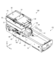
- FIG. 1 is a perspective view showing an example of a wiper unit according to this embodiment.
- FIG. 2 is a perspective view showing an example of the wiper unit according to this embodiment.
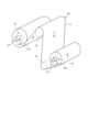
- FIG. 3 is a perspective view showing an example of the wiping portion.
- FIG. 4 is a diagram showing an example of a take-up roller and a take-up gear.
- FIG. 5 is a diagram showing an example of the internal configuration of the housing.
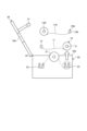
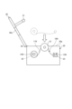
- FIG. 6 is an enlarged view showing the configuration of part of the housing.
- FIG. 7 is a diagram showing an example of the replacement process of the wiping portion.
- FIG. 8 is a diagram showing an example of the replacement process of the wiping portion.
- FIG. 9 is a diagram showing an example of the replacement process of the wiping portion.
- FIG. 1 is a perspective view showing an example of a wiper unit according to this embodiment.
- FIG. 2 is a perspective view showing an example of the wiper unit according to this embodiment.
- FIG. 3 is a perspective view showing
- FIG. 10 is a diagram showing an example of the replacement process of the wiping portion.
- FIG. 11 is a diagram showing an example of the replacement process of the wiping portion.
- FIG. 12 is a diagram showing an example of a drive mechanism.
- FIG. 13 is a diagram showing how the housing moves.
- FIG. 14 is a diagram showing how the housing moves.
- FIG. 15 is a diagram showing how the housing moves, and is a diagram showing the main part.
- FIG. 16 is a diagram showing how the housing moves, and is a diagram showing a main part.
- FIG. 17 is a diagram showing how the housing moves, and is a diagram showing the main part.
- FIG. 18 is a diagram illustrating an example of a transport mechanism; FIG.
- FIG. 19 is a diagram showing an example of pinion gears and planetary gears viewed from the -Y side.
- FIG. 20 is a diagram showing an example of pinion gears and planetary gears viewed from the -Y side.
- FIG. 21 is a diagram showing an example of pinion gears and planetary gears viewed from the -Y side.
- the directions in the drawing are explained using the XYZ coordinate system.
- the XY plane is a plane parallel to the floor on which the wiper unit is placed when the wiper unit is used.
- the moving direction of the housing 20, which will be described later is expressed as the X direction
- the direction perpendicular to the X direction on the XY plane is expressed as the Y direction.
- a direction perpendicular to the XY plane is referred to as a Z direction.
- the direction of the arrow in the drawing is the + direction
- the direction opposite to the direction of the arrow is the - direction.
- FIGS. 1 and 2 are perspective views showing an example of the wiper unit 100 according to this embodiment.
- the wiper unit 100 includes a wiping portion 10, a housing 20, a lid body 30, a drive mechanism 40, and a controller (not shown).
- the wiper unit 100 is mounted in a device, such as a printing apparatus, that has an ejection head that ejects liquid, and wipes off the liquid adhering to the ejection head.
- the wiping unit 10 has a wiping body 11 , a delivery roller 12 and a winding roller 13 .
- the wiping part 10 holds or absorbs the liquid adhering to the ejection head.
- the wiping body 11 is formed in a sheet shape. As such a wiping body 11, for example, a nonwoven fabric is used. Other materials may be used as the wiping body 11 .
- FIG. 3 is a perspective view showing an example of the wiping part 10.
- the wiping body 11 is provided with a base end portion 11 a fixed to the delivery roller 12 and a tip end portion 11 b fixed to the take-up roller 13 .
- the wiping body 11 is wound around the delivery roller 12 at the base end 11a side and fixed without being wound around the take-up roller 13 at the tip end portion 11b. Every time a wiping operation is performed from this state, the wiping body 11 is wound by the take-up roller 13 , and accordingly the wiping body 11 is delivered from the delivery roller 12 .
- the wiping body 11 may have a free end, for example, a free end, and may be fed out by a housing-side roller and a lid-side roller, which will be described later, and wound up by the winding roller 13 .
- the wiping unit 10 can handle the wiping body 11, the feed roller 12 and the take-up roller 13 as a unit.
- the wiping unit 10 can be attached to and detached from the housing 20 as a unit including the wiping body 11 , the delivery roller 12 and the take-up roller 13 .
- the delivery roller 12 is rotatably supported by a delivery side bearing 22 of the housing 20 described later, and the winding roller 13 is on the winding side of the housing 20 described later. It is rotatably supported by bearings 23 .
- a delivery-side gear 14 is provided on the delivery roller 12 .
- the delivery roller 12 is rotatable integrally with the delivery side gear 14 .
- a take-up gear 15 is provided on the take-up roller 13 .
- the take-up roller 13 is rotatable integrally with the take-up side gear 15 .
- the take-up gear 15 is supported by the take-up bearing 23 and meshes with a transmission gear 25 , which will be described later.
- FIG. 4 is a diagram showing an example of the winding roller 13 and the winding-side gear 15. As shown in FIG. FIG. 4 shows a cross-sectional configuration along a plane parallel to the YZ plane. As shown in FIG. 4, the take-up roller 13 has a wiping body holding portion 13a, a supported portion 13b, a tapered surface 13c, an elastic member supporting portion 13d, and an elastic member 13e.
- the wiping body holding portion 13a is, for example, cylindrical or cylindrical, and is a portion around which the wiping body 11 is wound.
- the supported portion 13 b is a portion supported by the winding-side bearing 23 of the housing 20 .
- the tapered surface 13c is a portion that connects the wiping body holding portion 13a and the supported portion 13b, and has a tapered shape in which the diameter is reduced from the wiping body holding portion 13a toward the supported portion 13b.
- the take-up gear 15 has an annular portion 15a with teeth formed on the outer peripheral side, and a connecting portion 15b extending from the annular portion 15a toward the tapered surface 13c.
- the connecting portion 15b has a facing surface 15c that faces the tapered surface 13c.
- the take-up gear 15 is held with the opposing surface 15c in contact with the tapered surface 13c.
- the elastic member supporting portion 13d is plate-shaped, for example, and is provided on the supported portion 13b.
- the elastic member 13e is supported by the elastic member supporting portion 13d, and applies elastic force to the connecting portion 15b of the take-up gear 15 toward the tapered surface 13c.
- the take-up gear 15 is held by the take-up roller 13 by the elastic force received from the elastic member 13e. As the take-up gear 15 rotates, a frictional force is generated between the facing surface 15c and the tapered surface 13c, and the take-up roller 13 is rotated by this frictional force.
- the wiping unit 10 When the wiping unit 10 is in use, tension is applied to the winding roller 13 from the wiping body 11 . Therefore, when the tension of the wiping body 11 is greater than the frictional force between the facing surface 15c and the tapered surface 13c, the take-up gear 15 idles with respect to the take-up roller 13.
- FIG. For example, when the diameter of the wiping body 11 wound around the take-up roller 13 is larger than the diameter of the lid-side roller 31 described later, when the lid-side roller 31 and the take-up roller 13 are rotated by the same angle, the lid-side roller The moving length of the outer circumference of the wiping body 11 wound by the winding roller 13 is larger than the moving length of the outer circumference of the wiping member 31 .
- the wiping body 11 is pulled from the take-up roller 13 side.
- the tension acting on the take-up roller 13 is greater than the elastic force of the elastic member 13 e , so that the take-up gear 15 idles with respect to the take-up roller 13 .
- the amount of rotation of the take-up gear 15 and the amount of rotation of the take-up roller 13 are adjusted according to how the wiping body 11 is taken up by the take-up roller 13 .
- the delivery roller 12 and the delivery side gear 14 provided on the delivery roller 12 have the same configurations as the winding roller 13 and the winding side gear 15, respectively.
- the feeding-side gear 14 is restricted in rotation by a stopper 24 provided on the housing 20, which will be described later. Therefore, loosening of the wiping body 11 on the delivery roller 12 can be suppressed.
- tension from the wiping body 11 acts on the delivery roller 12 when the wiping body 11 is wound by the take-up roller 13 . Due to this tension, the delivery roller 12 rotates with respect to the delivery side gear 14 so that the wiping body 11 is delivered.
- the housing 20 removably accommodates the wiping part 10 including the wiping body 11 .
- the housing 20 has, for example, a rectangular parallelepiped box shape whose longitudinal direction is the X direction, and has an opening 20a at the upper end in the Z direction.
- the opening 20a is an opening through which the wiping part 10 including the wiping body 11 can be put in and taken out.
- FIG. 5 is a diagram showing an example of the internal configuration of the housing 20.
- the housing 20 has housing-side rollers 21 , delivery-side bearings 22 , take-up-side bearings 23 , stoppers 24 , and transmission gears 25 .
- the housing-side roller 21 has a roller shaft 21a.
- the roller shaft 21a is arranged along the Y direction. Both ends of the roller shaft 21 a in the Y direction protrude from the housing-side roller 21 .
- the housing-side rollers 21 are rotatably supported by the walls 20b at both ends of the housing 20 in the Y direction using roller shafts 21a.
- the housing-side roller 21 is rotatable around a rotation axis parallel to the Y direction.
- the housing-side roller 21 is arranged so that a part thereof protrudes upward (in the +Z direction) from the opening 20a.
- the housing-side roller 21 supports the wiping body 11 while a part of the wiping body 11 is hung from above (+Z side).
- the housing 20 accommodates the wiping unit 10 in a state in which a part of the wiping body 11 is hung on the housing side roller 21 from above (+Z side).
- FIG. 6 is an enlarged view showing the configuration of part of the housing 20.
- the housing-side roller 21 is arranged movably in the Z direction, for example, in a state in which the roller shaft 21a is applied with an elastic force upward (+Z direction) by a linear spring 26.
- the housing-side roller 21 supports the wiping body 11 in the Z direction between it and a cover-side roller (conveyance roller) 31, which will be described later.
- the linear spring 26 can apply force in the +Z direction to the lid-side roller 31 .
- the delivery side bearing 22 rotatably supports the delivery roller 12 .
- the feeding-side bearings 22 are arranged on the wall portions 20b at both ends of the housing 20 in the Y direction.
- the delivery-side bearing 22 has an open top (+Z side end) so that the delivery roller 12 can be inserted and removed in the Z direction.
- the winding-side bearing 23 rotatably supports the winding roller 13 .
- the winding-side bearings 23 are arranged on the wall portions 20b at both ends of the housing 20 in the Y direction.
- the winding-side bearing 23 is open at its upper portion (+Z side end) so that the winding roller 13 can be inserted and removed in the Z direction.
- the stopper 24 meshes with the delivery side gear 14 while the delivery roller 12 is supported by the delivery side bearing 22 .
- the stopper 24 is fixed to the bottom portion 20d of the housing 20 and restricts the rotation of the feeding-side gear 14. As shown in FIG.
- the transmission gear 25 meshes with the take-up gear 15 while the take-up roller 13 is supported by the take-up bearing 23 . Further, the transmission gear 25 meshes with a lid body roller gear 35 when the lid body 30, which will be described later, is closed. The transmission gear 25 transmits the rotation transmitted from the drive mechanism 40 , which will be described later, to the take-up side gear 15 and the lid body roller gear 35 .
- the lid 30 is provided so that the opening 20a of the housing 20 can be opened and closed.
- the lid 30 is attached to the ⁇ X side wall 20c of the housing 20 via a hinge 32.
- the lid 30 is provided to be rotatable around the Y-axis by a hinge 32 with the wall portion 20c as a fulcrum.
- the lid 30 covers the opening 20a so as to expose the wiping body 11 hooked on the housing-side roller 21 to the outside.
- the lid 30 has lid-side rollers (conveyance rollers) 31 that support the wiping body 11 while covering the opening 20a.
- the lid-side roller 31 is arranged below the housing-side roller 21 (on the ⁇ Z side) in the closed state in which the lid 30 covers the opening 20a.
- the +Z side surface of the wiping body 11 supported by the housing side roller 21 that is, the surface facing the ejection surface of the ejection head or the like is applied to the cover side roller 31 .
- the lid-side roller 31 supports the wiping body 11 and conveys it to the take-up roller 13 side.
- the surface of the cover-side roller 31 that contacts the wiping body 11 is made of a material that easily generates a frictional force with the wiping body 11, such as a foam material such as sponge, but the material is not limited to this.
- the lid-side roller 31 has a lid-side roller gear 35 that rotates integrally with the lid-side roller 31 .
- the cover roller gear 35 meshes with the transmission gear 25 and rotates in conjunction with the rotation of the transmission gear 25 when the cover 30 is closed.
- FIG. 7 to 11 are diagrams showing an example of the replacement process of the wiping portion 10.
- FIG. 7 the wiping body 11 is wound around the winding roller 13 by repeatedly using the wiper unit 100 .
- the wiping body 11 needs to be replaced.
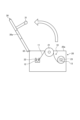
- the operator opens the lid 30 as shown in FIG.
- the lid 30 is opened by rotating about the Y-axis around the upper portion of the wall 20c on the ⁇ X side of the housing 20 by means of the hinge 32 .
- the opening 20a of the housing 20 is opened, and the lid-side roller 31 that presses the wiping body 11 downward ( ⁇ Z side) inside the housing 20 separates from the wiping body 11. This allows access to the inside of the housing 20 through the opening 20a.
- the wiping part 10 supported by the housing 20 is taken out.
- the delivery roller 12 with no wiping body 11 wound thereon is removed from the delivery side bearing 22
- the winding roller 13 with the used wiping body 11 wound thereon is removed from the winding side bearing 23 .
- the wiping body 11, the feed roller 12 and the take-up roller 13 are taken out as a unit from the opening 20a.
- a new wiping part 10N is attached to the housing 20.
- the wiping body 11N, delivery roller 12N, and take-up roller 13N of the new wiping portion 10N are put into the housing 20 through the opening 20a.
- the wiping body 11N is hung on the upper part of the housing side roller 21, the delivery roller 12N with the unused wiping body 11 wound thereon is supported by the delivery side bearing 22, and the wiping body 11 is not wound.
- the take-up roller 13N is supported by the take-up side bearing 23. - ⁇ As a result, a new wiping part 10N is attached to the housing 20.
- FIG. 10N As shown in FIG.
- the lid body 30 is closed as shown in FIG.
- the opening 20a is covered with the lid 30, and the wiping body 11N supported by the housing-side roller 21 protrudes upward from the opening window 30a.
- the position of the roller shaft 21a in the vertical direction is set so that only the wiping body 11N protrudes upward from the opening window 30a on the upper surface of the lid body 30.
- the lid-side roller 31 of the lid 30 pushes the wiping body 11N downward, and tension is generated in the wiping body 11N. This completes the replacement of the wiping portion 10 .
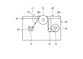
- the lid-side roller 31 is arranged closer to the wiping part 10 than the take-up roller 13 .
- tension is applied to the wiping body 11N, and the lead-out angle of the wiping body 11 from the housing side roller 21 toward the take-up roller 13 is kept constant by the cover side roller 31.
- FIG. According to this configuration, the wiping body 11 after wiping is removed from the housing side roller 21 at a constant angle regardless of the winding diameter of the take-up roller 13, so that the contaminated wiping body 11 after wiping reaches the opening window 30a. There is no fear of contaminating the lid body 30 due to contact.
- the lead-out angle of the wiping body 11 from the housing-side roller 21 may be substantially vertical as shown in FIG. .
- FIG. 12 is a diagram showing an example of the drive mechanism 40.
- the driving mechanism 40 has a moving mechanism 41 that moves the housing 20 and a transport mechanism 42 that transports the wiping body 11 .
- the drive mechanism 40 is provided on a base B arranged below the housing 20 (in the ⁇ Z direction).
- the moving mechanism 41 has a motor 43 , an output shaft 44 , a driving gear 45 and a rack gear 46 .
- the motor 43 rotates the output shaft 44 around the Y-axis under the control of the controller.
- the motor 43 can rotate the output shaft 44 by switching between opposite directions around the Y axis.
- the driving gear 45 has a disc shape, is fixed to the output shaft 44, and rotates around the Y-axis together with the output shaft 44.
- the driving gear 45 has a plurality of teeth 45a formed along the circumferential direction on the outer peripheral portion.
- the rack gear 46 is fixed to the bottom of the housing 20 and formed linearly along the X direction.
- the rack gear 46 has a plurality of teeth 46a formed along the X direction on the lower ( ⁇ Z side) surface. Teeth 46 a of rack gear 46 mesh with teeth 45 a of drive gear 45 . As the drive gear 45 rotates, the rack gear 46 moves in the X direction via the teeth 45a and 46a. The movement of the rack gear 46 in the X direction causes the housing 20 to move in the X direction.
- the moving mechanism 41 has an optical sensor 53 .
- the optical sensor 53 has a detection portion 53a that detects light emitted in the -Y direction from the light emission portion 53b.
- the light emitting section 53b is arranged on the +Y side of the detecting section 53a.
- the light-emitting portion 53b may be arranged on the base B, or may be arranged at a position different from the base B.
- the light emitting portion 53b may be arranged in the optical sensor 53, and the detecting portion 53a may detect the reflected light of the light emitted from the light emitting portion 53b.
- a plate member 54 is provided at the bottom of the housing 20 .
- the plate member 54 is not arranged on the +Y side of the detection section 53a, light from the light emitting section 53b reaches the detection section 53a and is detected by the detection section 53a.
- the plate member 54 is arranged on the +Y side of the detection section 53a, the light from the light emitting section 53b is blocked by the plate member 54 and does not reach the detection section 53a.
- the detection result of the detection unit 53a is supplied to the control unit.
- FIG. 13 and 14 are diagrams showing how the housing 20 moves.
- the housing 20 moves in the +X direction.
- the housing 20 is arranged at the wiping position P2 as shown in FIG.
- the motor 43 rotates in the opposite direction from the state where the housing 20 is arranged at the wiping position P2
- the rotation of the motor 43 is transmitted to the rack gear 46 via the output shaft 44 and the drive gear 45
- the rack gear 46 rotates.
- the housing 20 moves in the -X direction.
- the housing 20 is placed at the standby position P1 shown in FIG.
- 15 to 17 are diagrams showing how the housing 20 moves, and are diagrams showing the main parts.
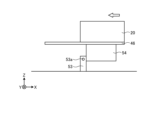
- the plate member 54 fixed to the bottom of the housing 20 approaches the optical sensor 53 as shown in FIG.
- the plate member 54 is arranged on the +Y side of the detection portion 53a of the optical sensor 53, as shown in FIG.
- the plate member 54 is removed from the position on the +Y side of the detection section 53a as shown in FIG.
- the light from the light emitting portion 53b reaches the detecting portion 53a without being blocked by the plate member .
- the detection unit 53a temporarily stops detecting light from the light emitting unit 53b after detecting light from the light emitting unit 53b (state shown in FIG. 15). 16), and then again switches to the state in which light from the light emitting portion 53b is detected (state in FIG. 17). Therefore, the control unit stops the driving of the motor 43 at the timing when the detection result of the detection unit 53a switches from the state in which light is not detected to the state in which light is detected. Thereby, the housing 20 can be appropriately stopped at the standby position P1.
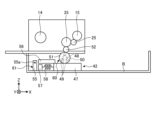
- FIG. 18 is a diagram showing an example of the transport mechanism 42.
- the transport mechanism 42 has a rack gear 47 , a pinion gear 48 , a planetary gear (relay section) 49 , a sun gear 50 , a first transmission gear 51 and a second transmission gear 52 .
- the rack gear 47 is arranged on the base B and formed linearly along the X direction.
- the rack gear 47 has a plurality of teeth 47a formed along the X direction on the upper (+Z side) surface.
- the rack gear 47 is arranged at a predetermined position in the base B near the standby position P1.
- the rack gear 47 is provided movably in the X direction.
- the ⁇ X side end of the rack gear 47 is connected to the elastic member supporting portion 57 via the elastic member 58 .
- the pinion gear 48, the planetary gear 49, the sun gear 50, the first transmission gear 51 and the second transmission gear 52 are each supported by the housing 20 so as to be rotatable around the Y axis.
- the pinion gear 48, the planetary gear 49, the sun gear 50, the first transmission gear 51 and the second transmission gear 52 are integral with the housing 20 and are movable in the X direction.
- the planetary gear 49 , the sun gear 50 , the first transmission gear 51 and the second transmission gear 52 constitute a transmission mechanism 60 that transmits the rotation of the pinion gear 48 to the lid side roller 31 .
- the pinion gear 48 is arranged at a position corresponding to the rack gear 47 in the X and Y directions. Specifically, when the housing 20 returns from the wiping position P2 to the standby position P1, the rack gear 47 and the pinion gear 48 move from a position before the standby position P1 to the standby position P1. Teeth 48 a are arranged to mesh with teeth 47 a of rack gear 47 . In this configuration, when the housing 20 moves in the opposite direction from the above, that is, when the housing 20 moves from the standby position P1 toward the wiping position P2, from the movement start position until it reaches the position past the standby position P1. The teeth 48a of the pinion gear 48 are also meshed with the teeth 47a of the rack gear 47 during this period.
- the planetary gear 49 is arranged on the -Y side of the pinion gear 48 .
- the sun gear 50 is provided coaxially with the pinion gear 48 .
- the sun gear 50 has a plurality of teeth 50a formed along the outer circumference along the circumferential direction.
- 19 to 21 are diagrams showing an example of the pinion gear 48 and the planetary gear 49 viewed from the -Y side. 19 to 21 also show the sun gear 50.
- FIG. 19 the planetary gear 49 is accommodated in a recess 48b provided on the -Y side of the pinion gear 48.
- the recesses 48 b are arranged at a plurality of locations (three locations in this embodiment) along the outer circumference of the sun gear 50 .
- the concave portion 48b is arranged, for example, at a position where the clockwise end in FIG.
- the planetary gear 49 moves inside the recess 48b as the pinion gear 48 rotates.
- the planetary gear 49 is arranged at the non-transmission position P4 away from the sun gear 50 in the concave portion 48b as the pinion gear 48 rotates. be.
- the teeth 49a of the planetary gear 49 do not mesh with the teeth 50a of the sun gear 50, and the sun gear 50 does not rotate. Therefore, the rotation of the pinion gear 48 is not transmitted to the lid-side roller 31 (non-transmission state).
- the planetary gear 49 is arranged in the recess 48b at the transmission position P3 in contact with the sun gear 50 as the pinion gear 48 rotates. .
- the planetary gear 49 arranged at the transmission position P3 only revolves and does not rotate. That is, the arrangement angle of the planetary gear 49 at the transmission position P3 is fixed.
- the rotation of the planetary gear 49 may be limited only at the transmission position P3, or may be fixed at a constant angle.
- the teeth 49a of the planetary gear 49 mesh with the teeth 50a of the sun gear 50, causing the sun gear 50 to rotate counterclockwise. That is, when the sun gear 50 meshes with the planetary gear 49, it rotates in the same direction as the pinion gear 48 (counterclockwise direction). Therefore, the rotation of the pinion gear 48 is transmitted to the lid-side roller 31 (transmission state).
- the first transmission gear 51 is fixed to the sun gear 50.
- the first transmission gear 51 is provided coaxially with the pinion gear 48 and the sun gear 50 and rotates together with the sun gear 50 .
- the first transmission gear 51 has a plurality of teeth 51a circumferentially formed on the outer circumference.
- the second transmission gear 52 is arranged above the first transmission gear 51 .
- a part of the second transmission gear 52 penetrates the bottom of the housing 20 and is arranged inside.
- the second transmission gear 52 is arranged rotatably around the Y-axis.
- the second transmission gear 52 has a plurality of teeth 52a circumferentially formed on the outer periphery.
- the second transmission gear 52 is arranged so that its lower side meshes with the first transmission gear 51 and its upper side meshes with the lid body roller gear 35 provided on the lid body 30 described above.
- the transport mechanism 42 also has an optical sensor 55 .
- the optical sensor 55 has a detection portion 55a that detects light emitted in the +Y direction from the light emission portion 55b.
- the light emitting section 55b is arranged on the -Y side of the detecting section 55a.
- the light-emitting portion 55b may be arranged on the base B, or may be arranged at a position different from the base B.
- FIG. It should be noted that the light emitting portion 55b may be arranged in the optical sensor 55, and the detecting portion 55a may detect the reflected light of the light emitted from the light emitting portion 55b.
- a light blocking member 56 is provided on the rack gear 47 .
- the light shielding member 56 When the light shielding member 56 is not arranged on the -Y side of the detection section 55a, light from the light emitting section 55b reaches the detection section 55a and is detected by the detection section 55a.
- the light blocking member 56 when the light blocking member 56 is arranged on the -Y side of the detection section 55a, the light from the light emitting section 55b is blocked by the light blocking member 56 and does not reach the detection section 55a.
- the detection result of the detection unit 55a is supplied to the control unit.
- the optical sensor 55 and the light shielding member 56 constitute a detection mechanism 61 that detects that the rotation of the lid-side roller 31 is restricted, as will be described later.
- FIG. 22 to 24 are diagrams showing an example of the operation of the transport mechanism 42.
- FIG. 22 to 24 show the state viewed from the -Y side.
- the teeth 48a of the pinion gear 48 mesh with the teeth 47a of the rack gear 47, and the pinion gear 48 rotates clockwise.
- the planetary gear 49 is arranged at the non-transmitting position P4 away from the sun gear 50 in the recess 48b. Therefore, the teeth 49a of the planetary gear 49 do not mesh with the teeth 50a of the sun gear 50, and the sun gear 50 does not rotate. Therefore, the transmission mechanism 60 is in a non-transmission state, and the wiping body 11 is not conveyed.
- the tooth 48a of the pinion gear 48 is moved to the position of the rack gear 47 from a position before the standby position P1 to the standby position P1.
- the pinion gear 48 meshes with the teeth 47a and rotates counterclockwise.
- the planetary gear 49 is arranged at the transmission position P3 in contact with the sun gear 50 . Therefore, the teeth 49a of the planetary gear 49 mesh with the teeth 50a of the sun gear 50, and the sun gear 50 rotates counterclockwise. Therefore, the transmission mechanism 60 is in the transmission state.
- the first transmission gear 51 rotates counterclockwise together with the sun gear 50 . Therefore, the second transmission gear 52 rotates clockwise, and the cover roller gear 35 meshing with the second transmission gear 52 rotates counterclockwise.
- the rotation of the cover roller gear 35 causes the cover side roller 31 to rotate, and the wiping body 11 is conveyed to the take-up roller 13 side. Due to the rotation of the cover-side roller 31, tension is generated in the wiping body 11, and the delivery roller 12 rotates counterclockwise, that is, in the direction in which the wiping body 11 is delivered. As a result, the wiping body 11 is delivered from the delivery roller 12 by a predetermined length.
- the transmission gear 25 meshing with the lid roller gear 35 rotates clockwise
- the winding-side gear 15 meshing with the transmission gear 25 rotates counterclockwise.
- the rotation of the take-up gear 15 causes the take-up roller 13 to rotate counterclockwise, thereby rotating in the direction in which the wiping body 11 is taken up.
- the wiping body 11 transported from the cover side roller 31 is wound up by the winding roller 13 .
- the transmission gear 25, the cover roller gear 35, the second transmission gear 52, the first transmission gear 51, the sun gear 50, the planetary gear 49, and the pinion gear 48, which directly or indirectly mesh with the take-up gear 15, are connected to each other. It will be in a state where it does not rotate while being meshed.
- the rack gear 47 remains engaged with the pinion gear 48 and moves in the -X direction together with the housing 20 including the pinion gear 48 .
- the movement of the rack gear 47 causes the elastic member 58 to contract, and the light blocking member 56 is arranged on the +Y side of the detection portion 55a of the optical sensor 55 . Therefore, the light from the light emitting portion 55b is blocked by the light shielding member 56 and does not reach the detecting portion 55a.
- the control section can determine the timing for replacing the wiping section 10 based on the detection result of the detection section 55 a of the optical sensor 55 .
- the control unit can output or notify the determination result.
- the optical sensor 55 and the light blocking member 56 constitute a detection mechanism 61 that detects that the rotation of the lid-side roller 31 is restricted.
- the wiper unit 100 has the wiping part 10 having the roll-shaped wiping body 11 and the opening 20a through which the wiping part 10 can be taken in and out.
- a housing 20 having housing-side rollers 21 disposed so as to protrude upward, housing the wiping unit 10 in a state in which a part of the wiping body 11 is hung from the housing-side rollers 21 from above;
- a lid body 30 is provided which covers the opening 20a so as to expose the wiping body 11 hung on the roller 21 to the outside, and has a lid body side roller 31 which conveys the wiping body 11 while covering the opening part 20a.
- the wiping part 10 can be taken in and out of the housing 20 through the opening 20a. Therefore, the wiping unit 10 can be replaced individually without dealing with the configuration necessary for the wiping operation on a cassette-by-cassette basis, so the running cost can be suppressed.
- the wiping part 10 is rotatably supported by the housing 20, the base end of the wiping body 11 is fixed, and the feed roller 12 feeds the wiping body 11 to the housing side roller 21. and a winding roller 13 which is rotatably supported by the housing 20, to which the tip of the wiping body 11 is fixed, and which winds up the wiping body 11 from the housing side roller 21.
- the wiping unit 10 which is integrated with the wiping body 11, the feed roller 12, and the take-up roller 13, can be easily replaced by inserting and withdrawing the unit.
- the take-up roller 13 has a take-up side gear 15 that can rotate integrally with the take-up roller 13, and the lid side roller 31 rotates integrally with the lid side roller 31. It has a cover roller gear 35 connected to rotate in conjunction with the take-up gear 15 .
- the housing 20 is movable in a predetermined direction, the rack gear 47 arranged along the predetermined direction, the pinion gear 48 meshing with the rack gear 47, and the rotation of the pinion gear 48.
- a transmission mechanism 60 capable of transmitting to the lid body roller gear 35 is further provided. With this configuration, the movement of the housing 20 and the conveying and winding operations of the wiping body 11 can be interlocked.
- the wiping body 11 is nonwoven fabric. Therefore, the wiping operation can be performed efficiently.
- the lid 30 is attached to the housing 20 via hinges 32 . This makes it possible to easily open and close the lid 30 .
- the wiper unit 100 includes a wiping body 11 extending in a belt shape, a housing 20 on which the wiping body 11 is mounted and which is movable in a predetermined direction, and a housing 20 which is movable in a predetermined direction.
- a moving mechanism 41 for moving and a transmission mechanism 60 for transmitting a moving force in a predetermined direction of the housing 20 and converting it into a moving force for moving the wiping body 11 are provided.
- the transmission mechanism 60 can interlock the movement of the housing 20 with the transport operation and winding operation of the wiping body 11 . Therefore, it is possible to provide the wiper unit 100 capable of simplifying the mechanism.
- the housing 20 has the cover-side roller 31 that rotates to convey the wiping body 11, and the conveying mechanism 42 includes a rack gear 47 arranged along a predetermined direction and a rack gear 47 .
- the transmission mechanism 60 can transmit the rotation of the pinion gear 48 to the lid side roller 31 .
- the transmission mechanism 60 has a transmission state in which rotation of the pinion gear 48 is transmitted to the lid side roller 31 and a non-transmission state in which rotation of the pinion gear 48 is not transmitted to the lid side roller 31. It has a switchable relay. With this configuration, it is possible to switch between a state in which the transport operation and the winding operation of the wiping body 11 are performed and a state in which the transport operation and the winding operation of the wiping body 11 are not performed.
- the transmission mechanism 60 transmits rotation to the lid side roller 31 so as to transport the wiping body 11 in one direction. With this configuration, the wiping body 11 can be efficiently transported and used.
- the transmission mechanism 60 is arranged at the transmission position P3 where the rotation of the pinion gear 48 is transmitted to the cover side roller 31 when the pinion gear 48 rotates in the first direction. It has a planetary gear 49 arranged at a non-transmitting position P4 that does not mesh with the pinion gear 48 when it rotates in a second direction opposite to the first direction, and the planetary gear 49 serves as a relay. In this configuration, the planetary gear 49 can efficiently switch between the transmission state and the non-transmission state.
- the housing 20 moves in a predetermined direction between the standby position P1 and the wiping position P2 where the wiping operation is performed.
- the second direction is the rotation direction when moving to the standby position P1
- the second direction is the rotation direction when the housing 20 moves from the standby position P1 to the wiping position P2.
- the rotation of the lid side roller 31 is restricted when the wiping body 11 is extended to the base end, and the detection mechanism 61 detects that the rotation of the lid side roller 31 is restricted. Further prepare. With this configuration, it is possible to efficiently detect the replacement timing of the wiping portion 10 .
- the transport mechanism 42 includes the rack gear 47 and the pinion gear 48, and the transmission mechanism 60 transmits the rotation of the pinion gear 48 to the lid side roller 31.
- the transmission mechanism can transmit the moving force of the housing 20 in a predetermined direction and convert it into a moving force for moving the wiping body 11 .
Landscapes
- Transmission Devices (AREA)
- Ink Jet (AREA)
Abstract
Description
P1 待機位置
P2 払拭位置
P3 伝達位置
P4 非伝達位置
10,10N 払拭部
11,11N 払拭体
11a 基端部
11b 先端部
12,12N 出しローラ
13,13N 巻き取りローラ
13a 払拭体保持部
13b 被支持部
13c テーパ面
13d,57 弾性部材支持部
13e,58 弾性部材
14 出し側ギア
15 巻き取り側ギア
15a 環状部
15b 接続部
15c 対向面
20 筐体
20a 開口部
20b,20c 壁部
20d 底部
21 筐体側ローラ
26 線状ばね
22 出し側軸受
23 巻き取り側軸受
24 ストッパ
25 伝達ギア
30 蓋体
30a 開口窓
31 蓋体側ローラ
32 ヒンジ
35 蓋体ローラギア
40 駆動機構
41 移動機構
42 搬送機構
43 モータ
44 出力軸
45 駆動ギア
45a,46a,47a,48a,49a,50a,51a,52a 歯
46,47 ラックギア
48 ピニオンギア
48b 凹部
49 遊星ギア
50 太陽ギア
51 第1伝達ギア
52 第2伝達ギア
53,55 光センサ
53a,55a 検出部
53b,55b 発光部
54 板部材
56 遮光部材
60 伝達機構
61 検出機構
100 ワイパユニット
Claims (13)
- 帯状に延在する払拭体と、
前記払拭体を載置し、所定方向に移動可能に設けられる筐体と、
前記筐体を前記所定方向に移動させる駆動機構と、
前記筐体の前記所定方向への移動力を、前記払拭体を移動する移動力に変換する伝達機構と
を備えるワイパユニット。 - 前記筐体は、回動により前記払拭体を搬送する搬送ローラを有し、
前記駆動機構は、前記所定方向に沿って配置されるラックギアと、前記ラックギアと噛み合うピニオンギアを備え、
前記伝達機構は、前記ピニオンギアの回転を前記搬送ローラに伝達可能とするものである
請求項1に記載のワイパユニット。 - 前記伝達機構は、前記ピニオンギアの回転を前記搬送ローラに伝達する伝達状態と、前記ピニオンギアの回転を前記搬送ローラに伝達しない非伝達状態とを切り替え可能な中継部を有する
請求項1又は請求項2に記載のワイパユニット。 - 前記伝達機構は、前記払拭体を一方向に搬送するように前記搬送ローラに回転を伝達する
請求項1から請求項3のいずれか一項に記載のワイパユニット。 - 前記伝達機構は、前記ピニオンギアが第1方向に回転する場合には前記ピニオンギアの回転を前記搬送ローラに伝達する伝達位置に配置され、前記ピニオンギアが前記第1方向とは反対の第2方向に回転する場合には前記ピニオンギアに噛み合わない非伝達位置に配置される遊星ギアを有し、
前記中継部は、前記遊星ギアである
請求項4に記載のワイパユニット。 - 前記筐体は、待機位置と、払拭動作を行う払拭位置との間を往復し、
前記第1方向は、前記筐体が前記払拭位置から前記待機位置に移動する場合の回転方向であり、
前記第2方向は、前記筐体が前記待機位置から前記払拭位置に移動する場合の回転方向である
請求項5に記載のワイパユニット。 - 前記搬送ローラは、前記払拭体が基端まで繰り出された場合に回転が規制され、
前記搬送ローラの回転が規制されたことを検出する検出機構を更に備える
請求項1から請求項6のいずれか一項に記載のワイパユニット。 - ロール状の払拭体を有する払拭部と、
前記払拭部を出し入れ可能な開口部を上部に有し、前記開口部から一部が上方に突出するように配置される筐体側ローラを有し、前記払拭体の一部が前記筐体側ローラに上側から掛けられた状態で前記払拭部を収容する筐体と、
前記筐体側ローラに掛けられた前記払拭体を外部に露出するように前記開口部を覆い、前記開口部を覆った状態で前記払拭体を搬送する蓋体側ローラを有する蓋体と
を備えるワイパユニット。 - 前記払拭部は、
前記筐体に回転可能に支持され、前記払拭体の基端が固定され、前記筐体側ローラに対して前記払拭体を繰り出す繰り出しローラと、
前記筐体に回転可能に支持され、前記払拭体の先端が固定され、前記筐体側ローラからの前記払拭体を巻き取る巻き取りローラと
を有する
請求項8に記載のワイパユニット。 - 前記巻き取りローラは、前記巻き取りローラと一体で回転可能な巻き取り側ギアを有し、
前記蓋体側ローラは、前記蓋体側ローラと一体で回転し、前記巻き取り側ギアと連動して回転するように該巻き取り側ギアに接続された蓋体ローラギアを有する
請求項9に記載のワイパユニット。 - 前記筐体は所定方向に移動可能であり、
前記所定方向に沿って配置されるラックギアと、
前記ラックギアと噛み合うピニオンギアと、
前記ピニオンギアの回転を前記蓋体ローラギアに伝達可能な伝達機構と
を更に備える請求項10に記載のワイパユニット。 - 前記払拭体は、不織布である
請求項8から請求項11のいずれか一項に記載のワイパユニット。 - 前記蓋体は、ヒンジを介して前記筐体に装着される
請求項8から請求項12のいずれか一項に記載のワイパユニット。
Priority Applications (1)
| Application Number | Priority Date | Filing Date | Title |
|---|---|---|---|
| US18/701,606 US20250091349A1 (en) | 2021-10-20 | 2022-10-20 | Wiper unit |
Applications Claiming Priority (4)
| Application Number | Priority Date | Filing Date | Title |
|---|---|---|---|
| JP2021171723A JP2023061658A (ja) | 2021-10-20 | 2021-10-20 | ワイパユニット |
| JP2021-171723 | 2021-10-20 | ||
| JP2021-171917 | 2021-10-20 | ||
| JP2021171917A JP7743261B2 (ja) | 2021-10-20 | 2021-10-20 | ワイパユニット |
Publications (1)
| Publication Number | Publication Date |
|---|---|
| WO2023068321A1 true WO2023068321A1 (ja) | 2023-04-27 |
Family
ID=86058304
Family Applications (1)
| Application Number | Title | Priority Date | Filing Date |
|---|---|---|---|
| PCT/JP2022/039051 Ceased WO2023068321A1 (ja) | 2021-10-20 | 2022-10-20 | ワイパユニット |
Country Status (2)
| Country | Link |
|---|---|
| US (1) | US20250091349A1 (ja) |
| WO (1) | WO2023068321A1 (ja) |
Citations (6)
| Publication number | Priority date | Publication date | Assignee | Title |
|---|---|---|---|---|
| JP2006007577A (ja) * | 2004-06-25 | 2006-01-12 | Ricoh Printing Systems Ltd | インクジェット記録装置の印字部清掃機構 |
| JP2008006715A (ja) * | 2006-06-29 | 2008-01-17 | Konica Minolta Medical & Graphic Inc | ヘッドメンテナンス装置 |
| JP2019043031A (ja) * | 2017-09-01 | 2019-03-22 | セイコーエプソン株式会社 | ワイパーユニット、液体噴射装置及びワイピング部材のエンド状態判断方法 |
| JP2020203442A (ja) * | 2019-06-18 | 2020-12-24 | 株式会社ミマキエンジニアリング | クリーニング機構、インクジェット印刷装置 |
| JP2020203441A (ja) * | 2019-06-18 | 2020-12-24 | 株式会社ミマキエンジニアリング | 払拭装置、インクジェットプリンタ |
| JP2021109315A (ja) * | 2020-01-07 | 2021-08-02 | コニカミノルタ株式会社 | インクジェット記録装置 |
Family Cites Families (1)
| Publication number | Priority date | Publication date | Assignee | Title |
|---|---|---|---|---|
| US8672448B2 (en) * | 2011-11-11 | 2014-03-18 | Seiko Epson Corporation | Wiper unit and liquid ejecting apparatus |
-
2022
- 2022-10-20 WO PCT/JP2022/039051 patent/WO2023068321A1/ja not_active Ceased
- 2022-10-20 US US18/701,606 patent/US20250091349A1/en active Pending
Patent Citations (6)
| Publication number | Priority date | Publication date | Assignee | Title |
|---|---|---|---|---|
| JP2006007577A (ja) * | 2004-06-25 | 2006-01-12 | Ricoh Printing Systems Ltd | インクジェット記録装置の印字部清掃機構 |
| JP2008006715A (ja) * | 2006-06-29 | 2008-01-17 | Konica Minolta Medical & Graphic Inc | ヘッドメンテナンス装置 |
| JP2019043031A (ja) * | 2017-09-01 | 2019-03-22 | セイコーエプソン株式会社 | ワイパーユニット、液体噴射装置及びワイピング部材のエンド状態判断方法 |
| JP2020203442A (ja) * | 2019-06-18 | 2020-12-24 | 株式会社ミマキエンジニアリング | クリーニング機構、インクジェット印刷装置 |
| JP2020203441A (ja) * | 2019-06-18 | 2020-12-24 | 株式会社ミマキエンジニアリング | 払拭装置、インクジェットプリンタ |
| JP2021109315A (ja) * | 2020-01-07 | 2021-08-02 | コニカミノルタ株式会社 | インクジェット記録装置 |
Also Published As
| Publication number | Publication date |
|---|---|
| US20250091349A1 (en) | 2025-03-20 |
Similar Documents
| Publication | Publication Date | Title |
|---|---|---|
| RU2018114256A (ru) | Контейнер подачи проявителя | |
| US20070237485A1 (en) | Optical Fiber Rewinding Apparatus | |
| US9506503B2 (en) | Driving device | |
| KR100929056B1 (ko) | 화상 형성 장치 | |
| US6183153B1 (en) | Holder for roll-type print media, roll-type print media cassette, and printing apparatus | |
| WO2023068321A1 (ja) | ワイパユニット | |
| CN114347651A (zh) | 处理装置以及记录装置 | |
| JP2023061658A (ja) | ワイパユニット | |
| JP2023061784A (ja) | ワイパユニット | |
| US11192393B2 (en) | Cleaning device and image forming apparatus provided with the cleaning device | |
| JP7318456B2 (ja) | クリーニング装置およびこれを備えた画像形成装置 | |
| US7802934B2 (en) | Image generating apparatus having axially movable roller gear | |
| US12097705B2 (en) | Recording device | |
| JP2025148620A (ja) | ワイパユニット、及び、ワイピング方法 | |
| JP2020196617A (ja) | クリーニング装置およびこれを備えた画像形成装置 | |
| JP6030608B2 (ja) | 紙葉類搬送装置 | |
| JP2007031077A (ja) | 給紙装置 | |
| JP2018130911A (ja) | 印刷装置 | |
| JPH04148749A (ja) | 画像読取装置 | |
| JP5452526B2 (ja) | 自動分析装置 | |
| US20200376868A1 (en) | Cleaning device and image forming apparatus provided with the cleaning device | |
| JP2017200725A (ja) | 記録装置 | |
| KR20210032625A (ko) | 디스펜서 노즐 세정 장치 | |
| JP3353569B2 (ja) | フィルム自動搬送装置 | |
| JP2007050944A (ja) | 保湿ケース |
Legal Events
| Date | Code | Title | Description |
|---|---|---|---|
| 121 | Ep: the epo has been informed by wipo that ep was designated in this application |
Ref document number: 22883625 Country of ref document: EP Kind code of ref document: A1 |
|
| WWE | Wipo information: entry into national phase |
Ref document number: 18701606 Country of ref document: US |
|
| NENP | Non-entry into the national phase |
Ref country code: DE |
|
| 122 | Ep: pct application non-entry in european phase |
Ref document number: 22883625 Country of ref document: EP Kind code of ref document: A1 |
|
| WWP | Wipo information: published in national office |
Ref document number: 18701606 Country of ref document: US |