WO2023068311A1 - ガラス振動板、エキサイタ付きガラス振動板及び車両用窓ガラス - Google Patents
ガラス振動板、エキサイタ付きガラス振動板及び車両用窓ガラス Download PDFInfo
- Publication number
- WO2023068311A1 WO2023068311A1 PCT/JP2022/039008 JP2022039008W WO2023068311A1 WO 2023068311 A1 WO2023068311 A1 WO 2023068311A1 JP 2022039008 W JP2022039008 W JP 2022039008W WO 2023068311 A1 WO2023068311 A1 WO 2023068311A1
- Authority
- WO
- WIPO (PCT)
- Prior art keywords
- glass
- glass plate
- diaphragm
- exciter
- threaded portion
- Prior art date
- Legal status (The legal status is an assumption and is not a legal conclusion. Google has not performed a legal analysis and makes no representation as to the accuracy of the status listed.)
- Ceased
Links
Images





Classifications
-
- B—PERFORMING OPERATIONS; TRANSPORTING
- B32—LAYERED PRODUCTS
- B32B—LAYERED PRODUCTS, i.e. PRODUCTS BUILT-UP OF STRATA OF FLAT OR NON-FLAT, e.g. CELLULAR OR HONEYCOMB, FORM
- B32B17/00—Layered products essentially comprising sheet glass, or glass, slag, or like fibres
-
- B—PERFORMING OPERATIONS; TRANSPORTING
- B60—VEHICLES IN GENERAL
- B60J—WINDOWS, WINDSCREENS, NON-FIXED ROOFS, DOORS, OR SIMILAR DEVICES FOR VEHICLES; REMOVABLE EXTERNAL PROTECTIVE COVERINGS SPECIALLY ADAPTED FOR VEHICLES
- B60J1/00—Windows; Windscreens; Accessories therefor
-
- C—CHEMISTRY; METALLURGY
- C03—GLASS; MINERAL OR SLAG WOOL
- C03C—CHEMICAL COMPOSITION OF GLASSES, GLAZES OR VITREOUS ENAMELS; SURFACE TREATMENT OF GLASS; SURFACE TREATMENT OF FIBRES OR FILAMENTS MADE FROM GLASS, MINERALS OR SLAGS; JOINING GLASS TO GLASS OR OTHER MATERIALS
- C03C27/00—Joining pieces of glass to pieces of other inorganic material; Joining glass to glass other than by fusing
- C03C27/06—Joining glass to glass by processes other than fusing
-
- H—ELECTRICITY
- H04—ELECTRIC COMMUNICATION TECHNIQUE
- H04R—LOUDSPEAKERS, MICROPHONES, GRAMOPHONE PICK-UPS OR LIKE ACOUSTIC ELECTROMECHANICAL TRANSDUCERS; ELECTRIC HEARING AIDS; PUBLIC ADDRESS SYSTEMS
- H04R7/00—Diaphragms for electromechanical transducers; Cones
- H04R7/02—Diaphragms for electromechanical transducers; Cones characterised by the construction
- H04R7/04—Plane diaphragms
- H04R7/06—Plane diaphragms comprising a plurality of sections or layers
- H04R7/08—Plane diaphragms comprising a plurality of sections or layers comprising superposed layers separated by air or other fluid
-
- H—ELECTRICITY
- H04—ELECTRIC COMMUNICATION TECHNIQUE
- H04R—LOUDSPEAKERS, MICROPHONES, GRAMOPHONE PICK-UPS OR LIKE ACOUSTIC ELECTROMECHANICAL TRANSDUCERS; ELECTRIC HEARING AIDS; PUBLIC ADDRESS SYSTEMS
- H04R7/00—Diaphragms for electromechanical transducers; Cones
- H04R7/02—Diaphragms for electromechanical transducers; Cones characterised by the construction
- H04R7/12—Non-planar diaphragms or cones
Definitions
- the present invention relates to a vibrating glass plate, a vibrating glass plate with an exciter, and a window glass for a vehicle.
- Patent Literature 1 and Patent Literature 2 disclose a structure for transmitting the vibration of an electrically vibrating exciter (piezoelectric actuator) to a diaphragm such as a glass plate.
- an exciter is screwed so as to pass through an opening in a second plate facing the first plate with a core material interposed therebetween, and the exciter is attached to the first plate via a spacer. being contacted.
- an exciter is fixed to one end of a rod member, which is a vibration transmitting portion, and the other end of the rod member is adhered to the diaphragm via a rod holding member.
- Patent Document 2 also discloses a diaphragm structure including a plurality of substrates and an intermediate layer arranged between the substrates as a glass substrate (diaphragm structure).
- an object of the present invention is to provide a vibrating glass plate, a vibrating glass plate with an exciter, and a window glass for a vehicle, which are strongly fixed to an exciter, which is a vibrating device, and can accurately reproduce a predetermined vibration.
- the present invention consists of the following configurations.
- a glass plate a mount portion connected and fixed to the glass plate, A first threaded portion and a second threaded portion are formed in the mount portion, the first threaded portion and the second threaded portion are a combination of a right-hand thread structure and a left-hand thread structure;
- a glass diaphragm with an exciter comprising the glass diaphragm according to (1) above and an exciter fixed to the mount portion.
- a window glass for a vehicle wherein the glass diaphragm with an exciter according to (2) above is attached to a vehicle.
- the exciter which is a vibrating device, and can accurately reproduce predetermined vibrations.
- FIG. 1 is a schematic plan view of a glass diaphragm with an exciter.
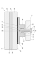
- FIG. 2 is a schematic cross-sectional view of the glass diaphragm shown in FIG. 1, taken along line II-II.
- FIG. 3 is a schematic plan view of a fixed portion of the mount section on the glass diaphragm.
- FIG. 4 is a schematic diagram of a fixed portion of the mount section on the glass diaphragm.
- FIG. 5 is a schematic cross-sectional view of a glass diaphragm with a mount section fixed to the fourth surface.
- FIG. 6A is a schematic cross-sectional view showing a configuration example with another mounting structure for the exciter.
- FIG. 6A is a schematic cross-sectional view showing a configuration example with another mounting structure for the exciter.
- FIG. 6B is a schematic cross-sectional view showing a configuration example with another mounting structure for the exciter.
- FIG. 6C is a schematic cross-sectional view showing a configuration example with another mounting structure for the exciter.
- FIG. 6D is a schematic plan view showing a configuration example with another mounting structure for the exciter.
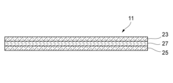
- FIG. 7 is a schematic cross-sectional view of a glass diaphragm made of laminated glass.
- FIG. 8 is a plan view of a vehicle in which the glass diaphragm with an exciter is applied to the window glass.
- FIG. 1 is a schematic plan view of a glass diaphragm 100 with an exciter.
- the exciter-equipped glass diaphragm 100 includes a glass diaphragm 11 and an exciter 13 that generates vibration. By driving the exciter 13, the glass diaphragm 11 is vibrated to generate a desired sound. .
- the exciter 13 is a vibrating device that uses an attached object as a diaphragm and generates sound from the diaphragm.
- the exciter 13 attached to the glass diaphragm 11 imparts vibration to the glass diaphragm 11 to generate sound, for example, enhancing the acoustic effect in the vehicle.
- a known exciter can be used for the exciter 13 .
- the exciter-equipped glass diaphragm 100 when the exciter-equipped glass diaphragm 100 is provided as a side window of a vehicle, the exciter 13 is arranged on the connection portion 15 side with the lifting mechanism (not shown) below the belt line BL. As a result, the sound generated from the glass diaphragm 11 can be supplied into the vehicle interior.
- the beltline BL corresponds to the lower side of the opening when the side window is fully closed when the side window is attached to the vehicle (door).
- the glass diaphragm 11 may be laminated glass made up of a plurality of glass plates, or may be single-plate glass made up of one glass plate. In this configuration example, a glass diaphragm 11 made of laminated glass will be described as an example.
- FIG. 2 is a schematic cross-sectional view of the glass diaphragm 11 shown in FIG. 1 taken along line II-II.
- FIG. 3 is a schematic plan view of a fixed portion of the mount portion 41 on the glass diaphragm 11.
- the glass diaphragm 11 is composed of laminated glass having a first glass plate 23, a second glass plate 25, and an intermediate layer 27 between the first glass plate 23 and the second glass plate 25. be done.
- the intermediate layer 27 is composed of an intermediate film such as resin, a fluid layer such as liquid or liquid crystal, or a gel layer.
- the intermediate layer 27 has a function of preventing resonance between the first glass plate 23 and the second glass plate 25 or damping vibration of resonance.
- the intermediate layer 27 may be an air layer without an intermediate film, fluid layer or gel layer.
- spacers are provided to define the thickness of the air layer at predetermined intervals, to prevent resonance between the first glass plate 23 and the second glass plate 25, or to dampen vibration of resonance. may be provided at predetermined intervals (in plan view), in which case the intermediate layer 27 may not be entirely filled with air.
- the thickness of the first glass plate 23 is preferably 0.5 mm to 15 mm, more preferably 0.8 mm to 10 mm, even more preferably 1.0 mm to 8 mm, and the thickness of the second glass plate 25 is preferably 0.5 mm to 15 mm, more preferably 0.8 mm to 10 mm, even more preferably 1.0 mm to 8 mm.
- the glass diaphragm 11 only the first glass plate 23, or both the first glass plate 23 and the second glass plate 25 may be chemically strengthened glass or physically strengthened glass. If the glass plate is tempered glass, the strength of the glass diaphragm 11 can be increased. Also, the first glass plate 23 and the second glass plate 25 may be curved glass having a curved shape. When the first glass plate 23 and the second glass plate 25 are curved glass, the appearance of the glass diaphragm 11 can be improved and the design can be enhanced.
- the first glass plate 23 and the second glass plate 25 may have, for example, a single-curved shape curved in one of the vertical and horizontal directions (with respect to one side of the frame) when mounted on a vehicle. , may have a compound curved shape curved both vertically and horizontally.
- the radius of curvature of the main surface to which the mount portion 41 is attached is preferably 3000 mm or more.
- the upper limit of the radius of curvature is not particularly limited, but is preferably 100000 mm or less, for example.
- the first glass plate 23 has a first surface 31 and a second surface 33.
- the main surface of the first glass plate 23 is the first surface 31 on the outside, and the main surface on the intermediate layer 27 side is the second surface 33 .
- the second glass plate 25 has a third surface 35 and a fourth surface 37 .
- the second glass plate 25 has a third surface 35 as a principal surface on the intermediate layer 27 side and a fourth surface 37 as an outer principal surface.
- the glass diaphragm 11 has a second glass plate 25 formed with a through hole 39 penetrating through the second glass plate 25 .
- This through hole 39 is formed in the thickness direction of the second glass plate 25 .
- the outer edge of the through-hole 39 is circular in plan view of the second glass plate 25 .
- the shape of the outer edge of the through-hole 39 is preferably circular, but may be various shapes such as an elliptical shape and a polygonal shape.
- the glass diaphragm 11 has a mount portion 41 to which the exciter 13 is attached. Thereby, the glass diaphragm 11 is vibrated by the exciter 13 attached to the mount portion 41 .
- This mount portion 41 is provided in a through hole 39 formed in the second glass plate 25 and fixed to the glass diaphragm 11 .
- the exciter 13 is fixed to the mount portion 41 and attached to the glass diaphragm 11 via the mount portion 41 .
- the mount part 41 can be made of materials such as metal materials such as aluminum or aluminum alloys, titanium alloys, magnesium alloys, and stainless steel, ceramics, glass, resin materials, carbon fibers, and composite materials made of these materials.
- the resin material include acrylic resins such as polymethyl methacrylate resin (PMMA), polycarbonate (PC), polyvinyl chloride (PVC), urethane, polypropylene (PP), ABS resin, etc., and are excellent in moldability. can be configured By using the above materials, cracks or the like do not occur in the mount portion 41, and sufficient connection strength can be obtained.
- the mount portion 41 preferably has a longitudinal wave sound velocity value of 2.0 ⁇ 10 3 m/s or more and an attenuation coefficient of 1.0 ⁇ 10 ⁇ 3 or more. If the longitudinal wave sound velocity value and the damping coefficient are set to the above numerical values, the reproducibility of the high frequency range can be improved, and the resonance vibration can be damped. Furthermore, it is more preferable that the mount portion 41 has the same longitudinal wave sound velocity value as at least one of the first glass plate 23 and the second glass plate 25 , and It is even more preferred to have longitudinal sound velocity values.
- the mount part 41 has a columnar part 43.
- the mount portion 41 has an extension portion 45 extending through the through hole 39 and extending around the through hole 39 in plan view of the second glass plate 25 .
- the projecting portion 45 is sandwiched between the first glass plate 23 and the second glass plate 25 .
- the projecting portion 45 faces the third surface 35 of the second glass plate 25 as a peripheral portion 47 at a portion located outside the through hole 39 .
- the mount portion 41 is connected to the second surface 33 of the first glass plate 23 and the third surface 35 of the second glass plate 25 via adhesive layers 51 and 53 .
- the mount portion 41 has a bottom surface facing the second surface 33 of the first glass plate 23 adhered by an adhesive layer 51 and a peripheral portion 47 facing the third surface 35 of the second glass plate 25 adhered by an adhesive layer 53 .
- the glass diaphragm 11 does not necessarily have the adhesive layers 51 and 53.
- the overhanging portion 45 is physically fixed between the first glass plate 23 and the second glass plate 25, so that the mount can be mounted.
- Part 41 may be fixed.
- the mount portion 41 itself may be made of a material having adhesive properties. In this case, the mount portion 41 is considered to include the adhesive layers 51 and 53. 53 may not be provided.
- adhesives such as thermosetting adhesives, light-curing adhesives, and moisture-curing adhesives can be used.
- thermosetting adhesives by devising the types and proportions of materials put in the adhesive, the crosslink density can be increased, and heat resistance, chemical resistance, and moisture resistance after curing can be improved.
- photocurable adhesive the work time can be shortened because the adhesive can be instantaneously adhered by irradiating ultraviolet rays.
- the adhesive layers 51 and 53 may be polyvinyl butyral resin (PVB).
- the thickness of the adhesive layers 51 and 53 is preferably 5 ⁇ m to 100 ⁇ m. When the thicknesses of the adhesive layers 51 and 53 are within the above range, the mount portion 41 can be fixed to the glass diaphragm 11 with a necessary and sufficient bonding strength.
- FIG. 4 is a schematic diagram of a fixed portion of the mount portion 41 on the glass diaphragm 11.
- the mount portion 41 has the area of S1 in the plan view of the second glass plate 25 .
- :S2 is preferably in the range of 1:1.2 to 1:100. With this area ratio, the mount portion 41 can be adhered and fixed to the first glass plate 23 and the second glass plate 25 satisfactorily.
- the peripheral portion 47 has a circular outer edge in plan view of the second glass plate 25 . That is, the peripheral portion 47 has an annular shape with a circular inner edge, and is rotationally symmetrical with respect to the central axis O of the mount portion 41 . Thereby, the mount portion 41 is adhesively fixed to the first glass plate 23 and the second glass plate 25 in a well-balanced manner.
- the shape of the peripheral portion 47 of the mount portion 41 in plan view of the second glass plate 25 is not limited to an annular shape as long as it is rotationally symmetrical about the central axis O of the mount portion 41 .
- the peripheral portion 47 of the mount portion 41 may have a polygonal shape such as a triangle or a square, or an elliptical shape, or may have a structure in which a plurality of radially extending portions are rotationally symmetrically arranged. If the peripheral portion 47 of the mount portion 41 has a shape extending radially from the outer edge shape, the mount portion 41 and the glass plate can be easily bonded to each other when the glass plate has a curved surface shape.
- the mount part 41 may be accommodated inside the through hole 39 of the second glass plate 25 in a state of being fixed to the glass diaphragm 11 .
- the mount portion 41 does not have a portion that protrudes outward from the fourth surface 37 of the second glass plate 25, the mount portion 41 does not interfere with the manufacturing and transportation of the glass diaphragm 11. , damage to the mount portion 41 can be easily avoided.
- the mount portion 41 provided inside the through hole 39 of the second glass plate 25 is attached to the second surface 33 of the first glass plate 23 via the adhesive layer 51 . , and further connected to the third surface 35 of the second glass plate 25 via the adhesive layer 53 . Therefore, when the exciter 13 as a vibrating device is attached to the mount portion 41 , both the first glass plate 23 and the second glass plate 25 constituting the glass vibrating plate 11 can be vibrated effectively by the exciter 13 .
- the mounting portion 41 is attached by bonding without providing the through hole 39 in the fourth surface 37 of the second glass plate 25, or the through hole of the second glass plate 25 is attached.
- the mount portion 41 is attached only to the second surface 33 of the first glass plate 23 through 39, the phase difference between the vibrations of the first glass plate 23 and the second glass plate 25 can be suppressed. Therefore, the sound reproduction capability of the glass diaphragm 11 can be improved, and the glass diaphragm 11 including the first glass plate 23 and the second glass plate 25 can function as a high-performance diaphragm.
- the phase difference between the first surface 31 and the fourth surface 37 is within 0.5 rad with respect to the frequency of 1 kHz at the position of the center of gravity.
- the phase difference is preferably within 0.3 rad, more preferably within 0.1 rad, and still more preferably within 0.05 rad.
- a through hole is formed through both the first glass plate 23 and the second glass plate 25, and a rod-shaped mount portion is passed through the through hole.
- Adhesive fixing to the first surface 31 and the fourth surface 37 is also conceivable.
- the mounting portion is complicated, and there is a problem that the mounting portion protrudes outward from the first surface 31 and the fourth surface 37 .
- the through hole 39 is formed only in the second glass plate 25, and the mount portion 41 is accommodated inside the through hole 39. Therefore, there is no complication of the mount portion 41, no portions protruding outward from the first surface 31 and the fourth surface 37 of the mount portion 41, and ingress of water at fixed portions of the mount portion 41 can be suppressed.
- the mount portion 41 is formed with a first screw portion 63 and a second screw portion 65 .
- the first threaded portion 63 and the second threaded portion 65 are a combination of a right-hand thread structure and a left-hand thread (reverse thread) structure.
- a right-hand thread structure is a thread structure that is tightened by turning it to the right (clockwise)
- a left-hand thread structure is a screw structure that is tightened by turning it to the left (counterclockwise).
- the first screw portion 63 has a right-hand thread structure
- the second screw portion 65 has a left-hand thread structure.
- the second screw portion 65 has a right-hand thread structure.
- the mount portion 41 has a circular concave portion 67 in plan view of the second glass plate 25 .
- the concave portion 67 is opened at the end surface of the columnar portion 43 .
- the outer surface of the recessed portion 67 is formed with a threaded structure that is a female thread, thereby forming the first threaded portion 63 having a first threaded diameter.
- the mount portion 41 has a circular concave portion 69 in plan view of the second glass plate 25 .
- This recessed portion 69 is a recessed portion having a diameter smaller than that of the recessed portion 67 and is formed in the bottom portion of the recessed portion 67 .
- the outer surface of the recessed portion 69 is formed with a threaded structure consisting of a female thread, thereby forming a second threaded portion 65 having a second threaded diameter.
- the concave portions 67 and 69 are each formed in a circular shape around the central axis O of the mount portion 41 . Therefore, the center of the first thread diameter of the first threaded portion 63 coincides with the center of the second threaded diameter of the second threaded portion 65 .
- the first thread diameter of the first threaded portion 63 and the second threaded diameter of the second threaded portion 65 are different from each other. Specifically, the first thread diameter of the first threaded portion 63 formed on the outer surface of the recess 67 is the second thread diameter of the second threaded portion 65 formed on the outer surface of the recess 69 having a diameter smaller than that of the recess 67. bigger than In addition, the outer edge of the first threaded portion 63 is outside the outer edge of the second threaded portion 65 in plan view of the second glass plate 25 .
- the exciter 13 attached to the mount portion 41 has an exciter body 71 and a convex portion 73 projecting from the exciter body 71 .
- a threaded portion 75 serving as a male screw is formed on the outer surface of the convex portion 73 .
- the convex portion 73 formed with the threaded portion 75 is screwed into and fastened to the first threaded portion 63 of the mount portion 41 .
- the exciter 13 is formed with an insertion hole 77 at its center, and a fastening bolt 81 is inserted into the insertion hole 77 .
- the fastening bolt 81 has a threaded portion 83 made of a male thread, and has a large-diameter head portion 85 at its rear end.
- the fastening bolt 81 is inserted into the insertion hole 77 of the exciter 13 from the tip side and screwed into the second screw portion 65 of the mount portion 41 .
- the exciter 13 fixed to the mount portion 41 is further firmly fixed by pressing the head portion 85 of the fastening bolt 81 against the rear surface of the exciter main body 71 .
- the exciter is attached to the mount portion 41 by using the first screw portion 63 formed on the outer surface of the recess 67 and the second screw portion 65 formed on the outer surface of the recess 69 . 13 is fixed. Therefore, the exciter 13 can be easily attached to and detached from the mount portion 41, and can be easily replaced. Further, the exciter 13 can be firmly fixed to the mount portion 41 by the first screw portion 63 and the second screw portion 65, and the glass diaphragm 11 can be vibrated effectively. This allows the glass diaphragm 11 to function as a high-performance diaphragm.
- first threaded portion 63 and the second threaded portion 65 are a combination of a right-hand thread structure and a left-hand thread structure, loosening can be suppressed, and the exciter 13 can be maintained in a good state of being fixed to the mount portion 41 .
- the exciter 13 is fixed by a second screw portion 65 different from the fastening portion of the first screw portion 63, and the back side of the exciter main body 71 is pressed by the head portion 85 of the fastening bolt 81, whereby the glass diaphragm is 11 lowest resonance frequencies can be adjusted.
- the screw diameters of the first threaded portion 63 and the second threaded portion 65 are different, and the outer edge of the first threaded portion 63 is wider than the outer edge of the second threaded portion 65 in a plan view of the second glass plate 25 . placed outside. Therefore, the exciter 13 can be firmly fixed to the mount portion 41 without loosening, and the fastening force of the first screw portion 63 and the fastening force of the second screw portion 65 can be applied in a well-balanced manner.
- the mount portion 41 can be mounted at the same center position.
- the exciter 13 can be fixed firmly and with good balance.
- the mount portion 41 is accommodated in the through hole 39 of the second glass plate 25 and fixed to the first glass plate 23 and the second glass plate 25 by bonding.
- the fixing of the mount portion 41 to the is not limited to the above configuration example.
- FIG. 5 is a schematic cross-sectional view of the glass diaphragm 11 in which the mount portion 41 is fixed to the fourth surface 37 of the second glass plate 25.
- the mount portion 41 may be adhesively fixed to the fourth surface 37 , which is the main surface of the second glass plate 25 , with an adhesive layer 55 .
- the mount portion 41 may be adhesively fixed to the main surface of the glass diaphragm 11 made of a single plate glass.
- the adhesive layer 55 preferably uses the same material as the adhesive layers 51 and 53 and has the same thickness as the adhesive layers 51 and 53 .
- the mount portion 41 itself may use a material having adhesiveness. In this case, the mount portion 41 is considered to include the adhesive layer 55, so the adhesive layer 55 is not provided as a member different from the mount portion 41. may
- the mounting structure of the exciter 13 to the mount portion 41 is not limited to the above configuration example, and may be another structure.
- a configuration example having another mounting structure for the exciter 13 will be described below.
- the same reference numerals are assigned to the same members or parts as those described above, and the description thereof will be omitted or simplified.
- FIG. 6A is a schematic cross-sectional view showing a configuration example with another mounting structure for the exciter 13.
- a screw structure is formed on the convex side surface of the columnar portion 43 protruding from the fourth surface 37 of the second glass plate 25 in the mount portion 41 to form the first screw portion 63 .
- the second threaded portion 65 is formed on the end surface of the columnar portion 43 of the mount portion 41 .
- the exciter body 71 of the exciter 13 attached to the mount portion 41 is formed with a screw portion 79 serving as a female screw on the mounting side of the mount portion 41 .
- the exciter 13 is fastened to the mount portion 41 by screwing the first screw portion 63 of the mount portion 41 into the screw portion 79 . Further, the exciter 13 is fastened to the mount portion 41 by screwing the screw portion 83 of the fastening bolt 81 inserted into the insertion hole 77 into the second screw portion 65 of the mount portion 41 . As a result, the exciter 13 is firmly fixed to the mount portion 41 without loosening by using the first threaded portion 63 and the second threaded portion 65 which have a reverse thread structure.
- FIG. 6B is a schematic cross-sectional view showing a configuration example with another mounting structure for the exciter 13.
- the columnar portion 43 of the mount portion 41 is formed in the shape of a round bar, and the columnar portion 43 protrudes from the fourth surface 37 of the second glass plate 25 .
- a screw structure is formed on the convex side surface of the columnar portion 43 of the mount portion 41 to form a first screw portion 63 and a second screw portion 65 .
- the first threaded portion 63 and the second threaded portion 65 are provided at the same position with the same diameter when the second glass plate 25 is viewed from above.
- both the right-hand thread structure and the left-hand thread structure are formed on the convex side surface of the columnar portion 43 of the mount portion 41, so that the first thread portion 63 and the second thread portion 65 are provided. ing. That is, the first threaded portion 63 and the second threaded portion 65 having a reverse thread structure are formed on the outer peripheral surface of the same axis.
- the exciter 13 attached to the mount part 41 has a threaded part 79 made of a female thread penetrating through the front and back of the exciter body 71 .
- the exciter 13 is fastened to the mount portion 41 by screwing the first screw portion 63 of the columnar portion 43 of the mount portion 41 into the screw portion 79 thereof. Further, the exciter 13 is screwed by screwing the second threaded portion 65 of the columnar portion 43 of the mount portion 41 into a fastening nut 89 having a threaded portion 79 of the exciter 13 and a threaded portion 87 formed of a reverse threaded female thread. It is fastened to the mount portion 41 .
- the exciter 13 is firmly fixed to the mount portion 41 without loosening by using the first threaded portion 63 and the second threaded portion 65 which have a reverse thread structure.
- the first threaded portion 63 and the second threaded portion 65 are a combination of a right-handed thread structure and a left-handed threaded structure formed on the convex side surface at the same position with the same diameter. The structure can be simplified compared to the case where the 63 and the second threaded portion 65 are formed at different positions.
- a first threaded portion 63 and a second threaded portion 65 having a combination of a right-handed thread structure and a left-handed threaded structure are formed on the concave side surface of the mount portion 41 at the same position with the same diameter, and a male thread is formed on the outer periphery.
- the exciter 13 may be fastened and fixed to the mount portion 41 by screwing the exciter 13 and the externally and reversely threaded bolts of the exciter 13 .
- FIGS. 6C and 6D are diagrams showing a configuration example having another mounting structure for the exciter 13, where FIG. 6C is a schematic cross-sectional view and FIG. 6D is a schematic plan view.
- the first threaded portion 63 is formed at a position where the center of the first threaded diameter coincides with the center of the mount portion 41 in plan view of the second glass plate 25 .
- the second threaded portion 65 is formed at a position outside the outer edge of the first threaded portion 63 .
- a plurality of second screw portions 65 (four in this example) are arranged rotationally symmetrically on the circumference around the first screw portion 63 in a plan view of the second glass plate 25 .
- a structure in which the mounting portion 41 is adhered and fixed to the fourth surface 37 that is the main surface of the second glass plate 25 by the adhesive layer 55 is illustrated.
- the exciter 13 attached to the mount portion 41 has a plurality of (in this example, four) through-holes 77 rotationally symmetrical on the circumference centered on the screw portion 75 in the exciter body 71 .
- the screw portion 75 of the exciter 13 is screwed into the first screw portion 63 of the mount portion 41 to be fastened.
- fastening bolts 81 are inserted into the plurality of insertion holes 77 of the exciter 13 , and the threaded portions 83 of these fastening bolts 81 are screwed into the plurality of second threaded portions 65 of the mount portion 41 .
- the exciter 13 fastened to the mount portion 41 is further firmly fixed by pressing the heads 85 of the plurality of fastening bolts 81 against the back surface of the exciter main body 71 .
- the exciter 13 is fixed at the center of the mount portion 41 by the first screw portion 63 , and furthermore, the first screw portion 63 and the first screw portion 63 are mounted at rotationally symmetrical positions around the fixed location of the first screw portion 63 .
- the exciter 13 is fixed to the mount portion 41 by a plurality of reverse threaded second screw portions 65 . As a result, the exciter 13 can be firmly and well-balanced fixed to the mount portion 41 .
- the glass diaphragm 11 may be a laminated glass in which a plurality of the glass plates 23 and 25 described above are laminated and an intermediate layer 27 is provided between the glass plates 23 and 25, or may be a single glass plate. . In the case of a single plate, the configuration can be simplified and the vibration characteristics can be easily controlled.
- FIG. 7 is a schematic cross-sectional view of a glass diaphragm 11 made of laminated glass.
- the glass diaphragm 11 is formed by laminating a first glass plate 23 and a second glass plate 25 (hereinafter also referred to as a pair of glass plates 23 and 25), and including an intermediate layer 27 between the glass plates 23 and 25. Configured.
- the shape of the plate surface of the glass diaphragm 11 is arbitrary, and may be square, rectangular, parallelogram, trapezoidal, other polygonal, circular, elliptical, or a combination of these shapes depending on the application site. good.
- the total thickness of the glass diaphragm 11 is preferably 2 mm or more, more preferably 3 mm or more, and even more preferably 4 mm or more. As a result, necessary and sufficient strength can be obtained even when applied to vehicles and buildings.
- the intermediate layer 27 prevents the glass plates 23 and 25 from resonating or attenuates the vibration of the resonance of the glass plates 23 and 25 . Due to the presence of the intermediate layer 27, the glass diaphragm 11 has a higher loss factor than the glass plate alone.
- the glass diaphragm 11 preferably has a larger loss factor because the vibration attenuation increases, and the loss factor of the glass diaphragm 11 at 25° C. is preferably 1 ⁇ 10 ⁇ 3 or more, more preferably 2 ⁇ 10 ⁇ 3 or more. , 5 ⁇ 10 ⁇ 3 or more is more preferable.
- the loss factor can be measured, for example, by a dynamic elastic modulus test method such as the resonance method, and the one calculated by the half-value width method is used.
- W is the frequency width at a point -3 dB lower than the peak value of the resonance frequency f and amplitude h of the material, that is, the point at the maximum amplitude -3 [dB].
- Define loss factor. Resonance can be suppressed by increasing the loss factor.
- a large loss factor means that the frequency width W is relatively large with respect to the amplitude h, and the peak is broadened. In other words, the greater the loss factor, the greater the vibration damping capacity.
- the loss factor is a value specific to the material, etc. For example, in the case of a
- the longitudinal wave sound velocity value in the plate thickness direction of the glass diaphragm 11 is preferably 4.0 ⁇ 10 3 m / s or more because the reproducibility of high-frequency sound is improved when the sound velocity is increased, and 4 It is more preferably 0.5 ⁇ 10 3 m/s or more, and even more preferably 5.0 ⁇ 10 3 m/s or more.
- the longitudinal wave sound velocity value is preferably 7.0 ⁇ 10 3 m/s or less.
- the longitudinal wave sound velocity value refers to the velocity at which the longitudinal wave propagates in the diaphragm.
- a longitudinal wave sound velocity value and a Young's modulus, which will be described later, can be measured by an ultrasonic pulse method described in Japanese Industrial Standards (JIS R 1602-1995).
- the glass diaphragm 11 has a high in-line transmittance, it can be applied as a translucent member. Therefore, the glass diaphragm 11 preferably has a visible light transmittance of 60% or more, more preferably 65% or more, and even more preferably 70% or more, as determined in accordance with Japanese Industrial Standards (JIS R 3106-1998).
- Examples of the translucent member include transparent speakers, transparent microphones, construction, opening members for vehicles, and the like.
- the difference between the refractive index of the intermediate layer 27 and the refractive index of the pair of glass plates 23 and 25 in contact with the intermediate layer 27 is preferably 0.2 or less, more preferably 0.1 or less, and even more preferably 0.01 or less.
- the glass plates 23 and 25 here may be inorganic glass or organic glass.
- organic glass PMMA-based resin, PC-based resin, PS-based resin, PET-based resin, PVC-based resin, cellulose-based resin, etc. can be used as general transparent resins.
- the resin material it is preferable to use a resin material that can be molded into a flat plate shape or a curved plate shape.
- a resin material compounded with a high-hardness filler, carbon fiber, Kevlar fiber, or the like is preferable.
- intermediate layer 27 between the plurality of laminated glass plates it is preferable to use a fluid layer such as a liquid or a liquid crystal, a gel-like material, or a solid film.
- a fluid layer such as a liquid or a liquid crystal, a gel-like material, or a solid film.
- the glass diaphragm 11 can achieve a high loss factor by providing a fluid layer containing liquid as the intermediate layer 27 between at least the pair of glass plates 23 and 25 . Above all, by setting the viscosity and surface tension of the fluid layer within a suitable range, the loss factor can be further increased. It is considered that this is because, unlike the case where the pair of glass plates are provided via an adhesive layer, the pair of glass plates do not adhere to each other and each glass plate maintains its vibration characteristics.
- the term "fluid” as used herein refers to liquids, semi-solids, mixtures of solid powders and liquids, solid gels (jelly-like substances) impregnated with liquids, etc. It means to include all things.
- the fluid layer preferably has a viscosity coefficient of 1 ⁇ 10 ⁇ 4 to 1 ⁇ 10 3 Pa ⁇ s at 25° C. and a surface tension of 15 to 80 mN/m at 25° C. If the viscosity is too low, it becomes difficult to transmit vibrations, and if the viscosity is too high, the pair of glass plates positioned on both sides of the fluid layer will adhere to each other and exhibit vibration behavior as a single glass plate, thus damping the resonance vibration. become difficult. On the other hand, if the surface tension is too low, the adhesion between the glass plates will decrease, making it difficult to transmit vibrations. If the surface tension is too high, the pair of glass plates positioned on both sides of the fluid layer are likely to adhere to each other, exhibiting vibration behavior as a single glass plate, making it difficult to attenuate resonance vibration.
- the fluid layer preferably has a viscosity coefficient of 1 ⁇ 10 ⁇ 4 to 1 ⁇ 10 3 Pa ⁇ s at 25° C. and a surface tension of 15 to 80 mN/m at 25° C. If the viscosity is too low, it becomes difficult to transmit vibrations, and if the viscosity is too high, the pair of glass plates positioned on both sides of the fluid layer will adhere to each other and exhibit vibration behavior as a single glass plate, thus damping the resonance vibration. become difficult. Also, if the surface tension of the fluid layer is too low, the adhesion between the glass plates will be reduced, making it difficult to transmit vibrations. If the surface tension is too high, the pair of glass plates positioned on both sides of the fluid layer are likely to adhere to each other, exhibiting vibration behavior as a single glass plate, making it difficult to attenuate resonance vibration.
- the viscosity coefficient of the fluid layer at 25° C. is more preferably 1 ⁇ 10 ⁇ 3 Pa ⁇ s or more, and even more preferably 1 ⁇ 10 ⁇ 2 Pa ⁇ s or more. Further, the viscosity coefficient of the fluid layer at 25° C. is more preferably 1 ⁇ 10 2 Pa ⁇ s or less, and even more preferably 1 ⁇ 10 Pa ⁇ s or less.
- the surface tension of the fluid layer at 25° C. is more preferably 20 mN/m or more, still more preferably 30 mN/m or more.
- the viscosity coefficient of the fluid layer can be measured using a rotational viscometer.
- the surface tension of the fluid layer can be measured by a ring method or the like.
- the fluid layer preferably has a vapor pressure of 1 ⁇ 10 4 Pa or less at 25° C. and 1 atm, more preferably 5 ⁇ 10 3 Pa or less, even more preferably 1 ⁇ 10 3 Pa or less.
- a seal or the like may be applied so that the fluid layer does not evaporate. In that case, it is necessary that the sealing material does not interfere with the vibration of the glass diaphragm.
- the thickness of the fluid layer may be 1/10 or less of the total thickness of the pair of glass plates.
- the following is preferable, 1/30 or less is more preferable, 1/50 or less is still more preferable, 1/70 or less is particularly preferable, and 1/100 or less is most preferable.
- the thickness of the fluid layer may be 100 ⁇ m or less, preferably 50 ⁇ m or less, more preferably 30 ⁇ m or less, even more preferably 20 ⁇ m or less, and 15 ⁇ m.
- the following are particularly preferable, and 10 ⁇ m or less is most preferable.
- the lower limit of the thickness of the fluid layer is preferably 0.01 ⁇ m or more from the viewpoint of film formability and durability.
- the fluid layer is chemically stable, and it is preferable that the fluid layer and the pair of glass plates located on both sides of the fluid layer do not react.
- Chemically stable means, for example, a material that is less altered (deteriorated) by light irradiation, or a material that does not solidify, vaporize, decompose, discolor, or chemically react with glass in a temperature range of at least -20 to 70°C. do.
- components of the fluid layer include water, oil, organic solvents, liquid polymers, ionic liquids and mixtures thereof. More specifically, propylene glycol, dipropylene glycol, tripropylene glycol, straight silicone oil (dimethyl silicone oil, methylphenyl silicone oil, methyl hydrogen silicone oil), modified silicone oil, acrylic acid polymer, liquid polybutadiene, glycerin Paste, fluorinated solvent, fluorinated resin, acetone, ethanol, xylene, toluene, water, mineral oil, mixtures thereof, and the like.
- it preferably contains at least one selected from the group consisting of propylene glycol, dimethylsilicone oil, methylphenylsilicone oil, methylhydrogensilicone oil and modified silicone oil, and more preferably contains propylene glycol or silicone oil as the main component.
- slurry in which powder is dispersed can also be used as a fluid layer.
- a uniform fluid is preferable for the fluid layer, but the slurry is effective when imparting design and functionality such as coloring and fluorescence to the glass diaphragm.
- the powder content in the fluid layer is preferably 0 to 10% by volume, more preferably 0 to 5% by volume.
- the particle size of the powder is preferably 10 nm to 1 ⁇ m, more preferably 0.5 ⁇ m or less.
- the fluid layer may contain a fluorescent material.
- a fluorescent material in this case, it may be a slurry-like fluid layer in which the fluorescent material is dispersed as powder, or a uniform fluid layer in which the fluorescent material is mixed as a liquid. This makes it possible to impart optical functions such as light absorption and light emission to the glass diaphragm.
- the intermediate layer 27 is a fluid layer containing a liquid and the first glass plate 23 is provided with the through holes 39 (see FIG. 2), the liquid in the intermediate layer 27 is sealed so as not to leak from the through holes 39.
- a structure is preferably provided.
- This encapsulation structure can be formed, for example, by a process similar to the liquid crystal polymer encapsulation process in liquid crystal displays. Specifically, a resin material (cured resin) that serves as a sealing material is applied in advance to the portion to be processed of the through hole 39 of the first glass plate 23 . Then, through holes 39 are formed in the laminated glass obtained by laminating the first glass plate 23 and the second glass plate 25 by using a laminated glass hole processing process.
- the through holes 39 are formed in the first glass plate 23 in advance, and the first glass plate 23 and the second glass plate 25 are overlapped.
- a ring-shaped sealing material is provided at a position corresponding to the through hole 39 of the second glass plate 25 according to the shape of the through hole 39 .
- the sealing material is sandwiched between the first glass plate 23 and the second glass plate 25, so that the fluid layer between the first glass plate 23 and the second glass plate 25 leaks through the through holes 39. to prevent
- a preferable material is a substance that satisfies any one of the following properties (1) to (3).
- the thickness of the intermediate layer 27 is 1 mm or less; (2) a compression storage modulus at a temperature of 25° C. of 1.0 ⁇ 10 4 Pa or less; (3) At a temperature of 25° C. and 1 Hz, the compression storage modulus is higher than the compression loss modulus.
- the fluidity of the intermediate layer 27 is suppressed and the loss factor is improved.
- the loss factor of the glass diaphragm is improved by increasing the thickness of the intermediate layer 27, there is a trade-off relationship in which the sound velocity value of the glass diaphragm 11 decreases as the intermediate layer 27 becomes thicker.
- the material of the intermediate layer 27 satisfies the characteristic (2), so that when the intermediate layer 27 is thin, the glass diaphragm 11 has a higher loss factor and secures a high sound velocity value. can.
- the thickness of the intermediate layer 27 is preferably 1 mm or less, more preferably 100 ⁇ m or less, even more preferably 10 ⁇ m or less, and particularly preferably 5 ⁇ m or less, from the viewpoint of obtaining a high loss factor of the glass diaphragm 11 . From the viewpoint of the surface roughness of the glass plates 23 and 25, it is preferably 1 ⁇ m or more.
- the material of the intermediate layer 27 preferably has a compression storage elastic modulus of 1.0 ⁇ 10 4 Pa or less at a temperature of 25° C., more preferably 7.0 ⁇ 10 3 Pa or less, and more preferably 5.0 ⁇ 10 3 Pa or less is more preferable. If the material satisfies the characteristic (2), the thinner the thickness of the intermediate layer 27, the higher the loss factor in the glass diaphragm 11 can be obtained. Moreover, from the viewpoint of fluidity, 1.0 ⁇ 10 2 Pa or more is preferable.
- a gel-like material can also be used as the material of the intermediate layer 27 .
- Materials constituting the intermediate layer 27 include, for example, carbon-based, fluorine-based, or silicone-based polymeric materials on the premise that any one of the above characteristics (1) to (3) is satisfied. .
- a composite material obtained by combining the above materials may be used. The above materials may be used alone or in combination of two or more.
- the ratio of the substance satisfying the above specific properties in the intermediate layer 27 is preferably 10% by mass to 100% by mass, more preferably 30% by mass to 100% by mass, even more preferably 50% by mass to 100% by mass, and 70% by mass. % to 100% by weight is particularly preferred.
- the material of the intermediate layer 27 includes polyvinyl butyral resin (PVB), ethylene-vinyl acetate copolymer resin (EVA), polyurethane resin, and silicone, which are suitably used as intermediate films for laminated glass. resin, polyethylene terephthalate resin, polycarbonate resin, and the like.
- ⁇ Glass plate> It is also possible to color at least one of the glass plates constituting the glass diaphragm 11 and at least one of the intermediate layer 27 . This is useful, for example, when the glass diaphragm 11 is desired to have a design, or when functions such as IR cut, UV cut, and privacy glass are added.
- the values of the peak tops of the resonance frequencies of one glass plate and the other glass plate are different, and it is more preferable that the resonance frequency ranges do not overlap.
- the resonance frequency ranges of the glass plate 23 and the glass plate 25 overlap or the peak top values are the same, one of the glass plates will resonate due to the existence of the intermediate layer 27.
- the vibration of the other glass plate is not synchronized. As a result, resonance is canceled to some extent, and a higher loss factor can be obtained than in the case of using only the glass plate.
- the resonance frequency (peak top) of one glass plate 23 is Qa
- the half width of the resonance amplitude is wa
- the resonance frequency (peak top) of the other glass plate 25 is Qb
- the half width of the resonance amplitude is wb, , preferably satisfies the following formula (1). (wa+wb)/4 ⁇
- ) between the resonance frequencies of the glass plates 23 and 25 increases, resulting in a high loss factor.
- the difference in mass between the glass plate 23 and the glass plate 25 is as small as possible, and it is more preferable that there is no difference in mass.
- the resonance of the lighter glass plate can be suppressed by the heavier glass plate, but it is difficult to suppress the resonance of the heavier glass plate by the lighter glass plate. That is, if the mass ratio is biased, the resonance vibrations cannot be canceled out in principle due to the difference in inertial force.
- the mass ratio of the glass plate 23 and the glass plate 25 represented by (glass plate 23/glass plate 25) is preferably 0.8 to 1.25 (8/10 to 10/8), more preferably 0.9 to 1.1. (9/10 to 10/9) is more preferred, and 1.0 (10/10, mass difference 0) is even more preferred.
- the thickness of the glass plates 23 and 25 is as thin as possible for use as a diaphragm.
- the thickness of each of the glass plates 23 and 25 may be 15 mm or less, preferably 10 mm or less, more preferably 5 mm or less, even more preferably 3 mm or less, and particularly preferably 1.5 mm or less.
- the glass plate is too thin, the effect of surface defects in the glass plate is significant, cracking is likely to occur, and strengthening treatment is difficult.
- each of the glass plates 23 and 25 is preferably 0.5 mm to 15 mm, more preferably 0.8 mm to 10 mm, and even more preferably 1.0 mm to 8 mm.
- the loss factor of the glass plate at 25° C. is preferably 1 ⁇ 10 ⁇ 4 or more, more preferably 3 ⁇ 10 ⁇ 4 or more, and even more preferably 5 ⁇ 10 ⁇ 4 or more.
- the upper limit is not particularly limited, it is preferably 5 ⁇ 10 ⁇ 3 or less from the viewpoint of productivity.
- both the glass plate 23 and the glass plate 25 have the above loss factor.
- the loss factor of the glass plate can be measured by the same method as the loss factor of the glass diaphragm 11 .
- At least one of the glass plate 23 and the glass plate 25 has a higher longitudinal wave sound velocity value in the plate thickness direction, which improves the reproducibility of the high-frequency sound range, and is therefore preferable as a diaphragm.
- the longitudinal wave sound velocity value of the glass plate is preferably 4.0 ⁇ 10 3 m/s or more, more preferably 5.0 ⁇ 10 3 m/s or more, and 6.0 ⁇ 10 3 m/s. The above is more preferable.
- the upper limit is not particularly limited, it is preferably 7.0 ⁇ 10 3 m/s or less from the viewpoint of productivity of the glass plate.
- both the glass plate 23 and the glass plate 25 satisfy the above sound velocity values.
- the sound velocity value of the glass plate can be measured by the same method as the longitudinal wave sound velocity value of the glass diaphragm.
- compositions of the glass plate 23 and the glass plate 25 are not particularly limited, the following ranges are preferable, for example.
- SiO 2 40 to 80% by mass, Al 2 O 3: 0 to 35% by mass, B 2 O 3 : 0 to 15% by mass, MgO: 0 to 20% by mass, CaO: 0 to 20% by mass, SrO: 0 to 20% by mass, BaO: 0 to 20% by mass, Li 2 O: 0 to 20% by mass, Na 2 O: 0 to 25% by mass, K 2 O: 0 to 20% by mass, TiO 2 : 0 to 10% by mass , and ZrO 2 : 0 to 10% by mass.
- the above composition accounts for 95% by mass or more of the entire glass.
- the compositions of the glass plate 23 and the glass plate 25 expressed in mol % based on the oxide are within the following range. SiO 2 : 55 to 75% by mass, Al 2 O 3 : 0 to 25% by mass, B 2 O 3 : 0 to 12% by mass, MgO: 0 to 20% by mass, CaO: 0 to 20% by mass, SrO: 0 ⁇ 20% by mass, BaO: 0 to 20% by mass, Li 2 O: 0 to 20% by mass, Na 2 O: 0 to 25% by mass, K 2 O: 0 to 15% by mass, TiO 2 : 0 to 5% by mass %, and ZrO 2 : 0 to 5% by mass.
- the above composition accounts for 95% by mass or more of the entire glass.
- the specific gravity of each of the glass plates 23 and 25 is the less energy the glass plates can be vibrated.
- the specific gravity of each of the glass plates 23 and 25 is preferably 2.8 or less, more preferably 2.6 or less, and even more preferably 2.5 or less.
- the lower limit is not particularly limited, it is preferably 2.2 or more.
- the specific elastic moduli of the glass plates 23 and 25 are preferably 2.5 ⁇ 10 7 m 2 /s 2 or more, more preferably 2.8 ⁇ 10 7 m 2 /s 2 or more, and 3.0 ⁇ 10 7 m 2 /s 2 or more is more preferable.
- the upper limit is not particularly limited, it is preferably 4.0 ⁇ 10 7 m 2 /s 2 or less.
- the glass plates may be used as the glass plates constituting the glass diaphragm 11 .
- the glass plates may all have different compositions, may all have the same composition, or may have the same composition and different compositions. may be used in combination with Among them, it is preferable to use two or more kinds of glass plates having different compositions from the viewpoint of vibration damping.
- the mass and thickness of the glass plates may be different, all the same, or partially different. Above all, it is preferable from the standpoint of vibration damping that all the constituent glass plates have the same mass.
- the rigidity of the glass plate structure can be improved by fixing a part or the entire circumference of the glass plate structure to the member on the stationary side.
- a physically strengthened glass plate or a chemically strengthened glass plate can also be used for at least one of the glass plates constituting the glass plate structure. This is useful to prevent breakage of the glass sheet construction.
- the glass plate positioned on the outermost surface of the glass plate structure be a physically strengthened glass plate or a chemically strengthened glass plate, and all of the glass plates constituting the glass plate structure are physically strengthened.
- a glass plate or a chemically strengthened glass plate is more preferred.
- crystallized glass or phase-separated glass is also useful in terms of increasing the longitudinal wave sound velocity value and strength.
- the glass plate structure may be flat or curved.
- the glass plate structure may, for example, have a curved surface that curves (bends) according to the installation location. Also, although not shown, it may have a shape that includes both a planar portion and a curved portion. That is, the glass plate structure may have a three-dimensional shape having at least a portion thereof curved in a concave or convex shape. In this way, by forming a three-dimensional shape in accordance with the installation location, the appearance at the installation location can be improved, and the design can be enhanced.
- the exciter 13 is connected to one main surface of the various glass plate structures described above via a mount portion 41.
- the exciter 13 may be connected to the region of the single plate through the mount portion 41 . That is, of the pair of glass plates 23 and 25 of the glass plate structure, the outer edge of one glass plate extends further outside than the other glass plate. Also, a suitable sealing material is provided at the end of one of the glass plates and the intermediate layer to seal the intermediate layer. Then, the exciter 13 is attached via the mount portion 41 to the portion (region of the single plate) extending to the outside of one of the glass plates.
- the glass diaphragm with an exciter described above can be applied to various uses.
- the glass diaphragm of the glass diaphragm with an exciter may be a vehicle window glass.
- FIG. 8 is a plan view of a vehicle in which the glass diaphragm with an exciter is applied to the window glass.
- the vehicle window glass composed of the glass diaphragm may be the front side window FSW of the vehicle 91, but is not limited to this.
- the rear side window RSW, windshield WS, rear window RW, roof glazing RG, front quarter window FQW, etc. of the vehicle 91 may be used.
- the vehicle glazing may be a wind deflector used in convertibles.
- the glass diaphragm may be glass for the interior of the vehicle.
- interior glass include those provided in various interior materials such as dashboards, center consoles, ceilings, door trims, pillar lining panels, and sun visors.
- Glass diaphragms can also be used as vehicle windows, building windows, structural members, and decorative panels with improved water repellency, anti-snow, anti-icing, and antifouling properties due to sonic vibration.
- the glass diaphragm with the exciter may be a vehicle-mounted or machine-mounted speaker.
- the glass diaphragm with an exciter is used, for example, as a member for electronic equipment, such as a full-range speaker, a speaker for bass reproduction in the 15 Hz to 200 Hz band, a large speaker with a diaphragm area of 0.2 m 2 or more, a flat speaker, a cylindrical speaker, and a transparent speaker.
- cover glass for mobile devices that function as speakers, cover glass for TV displays, video screens, displays where video and audio signals are generated from the same surface, speakers for wearable displays, electronic displays, lighting fixtures, etc. can.
- the speaker may be for music, alarm sound, or the like.
- the glass diaphragm with an exciter may be configured as an active noise control diaphragm for noise reduction.
- a vibration detection element it can function as a diaphragm for a microphone, a vibration sensor, or the like.
- the present invention is not limited to the above-described embodiments, and those skilled in the art can make modifications and applications by combining each configuration of the embodiments with each other, based on the description of the specification and well-known techniques. It is also contemplated by the present invention that it falls within the scope of protection sought.
- this specification discloses the following matters. (1) a glass plate; a mount portion connected and fixed to the glass plate, A first threaded portion and a second threaded portion are formed in the mount portion, the first threaded portion and the second threaded portion are a combination of a right-hand thread structure and a left-hand thread structure; A glass diaphragm in which the glass plate is vibrated via the mount section. According to this glass diaphragm, a device such as an exciter can be easily attached to and detached from the mount portion by using the first threaded portion and the second threaded portion of the mount portion, and the device can be easily replaced.
- the device can be firmly fixed to the mount portion by the first screw portion and the second screw portion, and the glass diaphragm can be vibrated effectively. This allows the glass diaphragm to function as a high-performance diaphragm. Furthermore, since the first threaded portion and the second threaded portion are a combination of a right-handed threaded structure and a left-handed threaded structure, it is possible to suppress loosening at the mutual fastening points and maintain a good fixed state of the device to the mount portion. .
- the center of the first screw diameter which is the diameter of the first screw portion, coincides with the center of the mount portion
- the second screw portion is the diameter of the first screw portion.
- the glass diaphragm according to (1) or (2) located outside the outer edge. According to this glass diaphragm, the device can be fixed to the mount portion at the center of the mount portion by the first screw portion, and the device can be fixed to the mount portion outside the outer edge of the first screw portion by the second screw portion.
- the device can be firmly fixed to the mount section by using the first threaded section and the second threaded section formed on the concave side surface of the mount section.
- the first threaded portion and the second threaded portion according to any one of (1) to (6), wherein the first threaded portion and the second threaded portion are formed by a combination of a convex side thread structure and a concave side thread structure.
- glass diaphragm According to this glass diaphragm, the device can be firmly fixed to the mount section by using the first threaded section and the second threaded section, which are a combination of screw structures formed on the convex side surface and the concave side surface of the mount section. .
- the first threaded portion and the second threaded portion have the same diameter and are at the same position,
- the device is attached to the mount section by using the first threaded section and the second threaded section formed on both convex side surfaces or both concave side surfaces. Can be firmly fixed without loosening.
- first threaded portion and the second threaded portion have the same diameter and the same position on both the convex side surfaces or both the concave side surfaces, the first threaded portion and the second threaded portion have a right-handed thread structure and a left-handed thread structure.
- the structure can be simplified as compared with the case where the two screw portions are formed at separate positions.
- the glass plate is a first glass plate having a first side and a second side;
- glass diaphragm According to this glass diaphragm, the mount portion is arranged in the through hole formed in the second glass plate, the mount portion is connected to the second surface of the first glass plate, and the third surface and the third surface of the second glass plate are connected to each other. It can be connected to at least one of the four faces.
- the exciter when an exciter, which is a vibrating device, is attached to the mount portion, the exciter can effectively vibrate both the first glass plate and the second glass plate that constitute the glass diaphragm, and the first glass plate can vibrate. Also, the phase difference of the vibration applied to the second glass plate can be suppressed. This allows the glass diaphragm including the first glass plate and the second glass plate to function as a high-performance diaphragm.
- the mount section has a structure extending through the through hole and extending around the through hole in a plan view of the second glass plate, and is between the first glass plate and the second glass plate.
- a glass diaphragm with an exciter comprising the glass diaphragm according to any one of (1) to (15) and an exciter fixed to the mount section.
- the exciter can be easily attached to and detached from the mount by using the first threaded portion and the second threaded portion of the mount, and can be easily replaced.
- the glass diaphragm can be vibrated effectively, and the glass diaphragm can function as a high-performance diaphragm.
- first threaded portion and the second threaded portion are a combination of a right-handed threaded structure and a left-handed threaded structure, it is possible to suppress loosening at the mutual fastening portion, and to maintain a good fixed state of the exciter to the mount portion. .
- a window glass for a vehicle wherein the glass diaphragm with an exciter according to (16) is attached to a vehicle.
- a desired sound can be generated from the vehicle window glass by attaching the glass diaphragm with the exciter to the vehicle as the vehicle window glass.
Landscapes
- Engineering & Computer Science (AREA)
- Chemical & Material Sciences (AREA)
- Multimedia (AREA)
- Signal Processing (AREA)
- Acoustics & Sound (AREA)
- Physics & Mathematics (AREA)
- Life Sciences & Earth Sciences (AREA)
- Materials Engineering (AREA)
- Organic Chemistry (AREA)
- Geochemistry & Mineralogy (AREA)
- General Chemical & Material Sciences (AREA)
- Chemical Kinetics & Catalysis (AREA)
- Ceramic Engineering (AREA)
- Mechanical Engineering (AREA)
- Diaphragms For Electromechanical Transducers (AREA)
Priority Applications (1)
| Application Number | Priority Date | Filing Date | Title |
|---|---|---|---|
| JP2023554731A JPWO2023068311A1 (https=) | 2021-10-22 | 2022-10-19 |
Applications Claiming Priority (2)
| Application Number | Priority Date | Filing Date | Title |
|---|---|---|---|
| JP2021-173469 | 2021-10-22 | ||
| JP2021173469 | 2021-10-22 |
Publications (1)
| Publication Number | Publication Date |
|---|---|
| WO2023068311A1 true WO2023068311A1 (ja) | 2023-04-27 |
Family
ID=86058271
Family Applications (1)
| Application Number | Title | Priority Date | Filing Date |
|---|---|---|---|
| PCT/JP2022/039008 Ceased WO2023068311A1 (ja) | 2021-10-22 | 2022-10-19 | ガラス振動板、エキサイタ付きガラス振動板及び車両用窓ガラス |
Country Status (2)
| Country | Link |
|---|---|
| JP (1) | JPWO2023068311A1 (https=) |
| WO (1) | WO2023068311A1 (https=) |
Citations (5)
| Publication number | Priority date | Publication date | Assignee | Title |
|---|---|---|---|---|
| JP2006180368A (ja) * | 2004-12-24 | 2006-07-06 | Fujitsu Ten Ltd | 車両の内装板を振動板としたスピーカ装置 |
| JP2010501046A (ja) * | 2006-08-17 | 2010-01-14 | アトラス・コプコ・エムエイアイ・ゲゼルシヤフト・ミツト・ベシユレンクテル・ハフツング | 摩擦チューブアンカー及びその膨張アダプター |
| WO2018155518A1 (ja) * | 2017-02-23 | 2018-08-30 | Agc株式会社 | ガラス板構成体 |
| WO2019172076A1 (ja) * | 2018-03-06 | 2019-09-12 | Agc株式会社 | スピーカー装置 |
| JP2020188413A (ja) * | 2019-05-16 | 2020-11-19 | 株式会社デンソーテン | スピーカ装置 |
-
2022
- 2022-10-19 WO PCT/JP2022/039008 patent/WO2023068311A1/ja not_active Ceased
- 2022-10-19 JP JP2023554731A patent/JPWO2023068311A1/ja active Pending
Patent Citations (5)
| Publication number | Priority date | Publication date | Assignee | Title |
|---|---|---|---|---|
| JP2006180368A (ja) * | 2004-12-24 | 2006-07-06 | Fujitsu Ten Ltd | 車両の内装板を振動板としたスピーカ装置 |
| JP2010501046A (ja) * | 2006-08-17 | 2010-01-14 | アトラス・コプコ・エムエイアイ・ゲゼルシヤフト・ミツト・ベシユレンクテル・ハフツング | 摩擦チューブアンカー及びその膨張アダプター |
| WO2018155518A1 (ja) * | 2017-02-23 | 2018-08-30 | Agc株式会社 | ガラス板構成体 |
| WO2019172076A1 (ja) * | 2018-03-06 | 2019-09-12 | Agc株式会社 | スピーカー装置 |
| JP2020188413A (ja) * | 2019-05-16 | 2020-11-19 | 株式会社デンソーテン | スピーカ装置 |
Also Published As
| Publication number | Publication date |
|---|---|
| JPWO2023068311A1 (https=) | 2023-04-27 |
Similar Documents
| Publication | Publication Date | Title |
|---|---|---|
| US11290807B2 (en) | Speaker device | |
| US12023894B2 (en) | Glass sheet composite | |
| JP7231071B2 (ja) | 振動板 | |
| JP7511115B2 (ja) | 振動装置 | |
| US12427749B2 (en) | Glass plate structure, diaphragm, and opening member | |
| WO2022158542A1 (ja) | 遮音装置 | |
| WO2023063368A1 (ja) | エキサイタ付きガラス振動板、車両用振動板及び建築物用振動板 | |
| US11385678B2 (en) | Display device and television device | |
| JP7715501B2 (ja) | 振動装置 | |
| US20200230922A1 (en) | Glass sheet composite | |
| WO2023068311A1 (ja) | ガラス振動板、エキサイタ付きガラス振動板及び車両用窓ガラス | |
| WO2023063370A1 (ja) | ガラス振動板、ガラス振動板の製造方法、エキサイタ付きガラス振動板、車両用振動板及び建築物用振動板 | |
| WO2023068310A1 (ja) | ガラス振動板、エキサイタ付きガラス振動板及び車両用窓ガラス |
Legal Events
| Date | Code | Title | Description |
|---|---|---|---|
| 121 | Ep: the epo has been informed by wipo that ep was designated in this application |
Ref document number: 22883615 Country of ref document: EP Kind code of ref document: A1 |
|
| ENP | Entry into the national phase |
Ref document number: 2023554731 Country of ref document: JP Kind code of ref document: A |
|
| NENP | Non-entry into the national phase |
Ref country code: DE |
|
| 122 | Ep: pct application non-entry in european phase |
Ref document number: 22883615 Country of ref document: EP Kind code of ref document: A1 |