WO2023068268A1 - 付加製造試験体の変形部の変形量の測定方法及び付加製造の適正条件の決定方法 - Google Patents
付加製造試験体の変形部の変形量の測定方法及び付加製造の適正条件の決定方法 Download PDFInfo
- Publication number
- WO2023068268A1 WO2023068268A1 PCT/JP2022/038762 JP2022038762W WO2023068268A1 WO 2023068268 A1 WO2023068268 A1 WO 2023068268A1 JP 2022038762 W JP2022038762 W JP 2022038762W WO 2023068268 A1 WO2023068268 A1 WO 2023068268A1
- Authority
- WO
- WIPO (PCT)
- Prior art keywords
- deformation
- additive manufacturing
- measuring
- manufacturing
- base plate
- Prior art date
- Legal status (The legal status is an assumption and is not a legal conclusion. Google has not performed a legal analysis and makes no representation as to the accuracy of the status listed.)
- Ceased
Links
Images




Classifications
-
- B—PERFORMING OPERATIONS; TRANSPORTING
- B33—ADDITIVE MANUFACTURING TECHNOLOGY
- B33Y—ADDITIVE MANUFACTURING, i.e. MANUFACTURING OF THREE-DIMENSIONAL [3D] OBJECTS BY ADDITIVE DEPOSITION, ADDITIVE AGGLOMERATION OR ADDITIVE LAYERING, e.g. BY 3D PRINTING, STEREOLITHOGRAPHY OR SELECTIVE LASER SINTERING
- B33Y10/00—Processes of additive manufacturing
-
- B—PERFORMING OPERATIONS; TRANSPORTING
- B22—CASTING; POWDER METALLURGY
- B22F—WORKING METALLIC POWDER; MANUFACTURE OF ARTICLES FROM METALLIC POWDER; MAKING METALLIC POWDER; APPARATUS OR DEVICES SPECIALLY ADAPTED FOR METALLIC POWDER
- B22F10/00—Additive manufacturing of workpieces or articles from metallic powder
- B22F10/20—Direct sintering or melting
- B22F10/28—Powder bed fusion, e.g. selective laser melting [SLM] or electron beam melting [EBM]
-
- B—PERFORMING OPERATIONS; TRANSPORTING
- B22—CASTING; POWDER METALLURGY
- B22F—WORKING METALLIC POWDER; MANUFACTURE OF ARTICLES FROM METALLIC POWDER; MAKING METALLIC POWDER; APPARATUS OR DEVICES SPECIALLY ADAPTED FOR METALLIC POWDER
- B22F10/00—Additive manufacturing of workpieces or articles from metallic powder
- B22F10/30—Process control
- B22F10/31—Calibration of process steps or apparatus settings, e.g. before or during manufacturing
-
- B—PERFORMING OPERATIONS; TRANSPORTING
- B22—CASTING; POWDER METALLURGY
- B22F—WORKING METALLIC POWDER; MANUFACTURE OF ARTICLES FROM METALLIC POWDER; MAKING METALLIC POWDER; APPARATUS OR DEVICES SPECIALLY ADAPTED FOR METALLIC POWDER
- B22F10/00—Additive manufacturing of workpieces or articles from metallic powder
- B22F10/80—Data acquisition or data processing
- B22F10/85—Data acquisition or data processing for controlling or regulating additive manufacturing processes
-
- B—PERFORMING OPERATIONS; TRANSPORTING
- B33—ADDITIVE MANUFACTURING TECHNOLOGY
- B33Y—ADDITIVE MANUFACTURING, i.e. MANUFACTURING OF THREE-DIMENSIONAL [3D] OBJECTS BY ADDITIVE DEPOSITION, ADDITIVE AGGLOMERATION OR ADDITIVE LAYERING, e.g. BY 3D PRINTING, STEREOLITHOGRAPHY OR SELECTIVE LASER SINTERING
- B33Y30/00—Apparatus for additive manufacturing; Details thereof or accessories therefor
-
- B—PERFORMING OPERATIONS; TRANSPORTING
- B22—CASTING; POWDER METALLURGY
- B22F—WORKING METALLIC POWDER; MANUFACTURE OF ARTICLES FROM METALLIC POWDER; MAKING METALLIC POWDER; APPARATUS OR DEVICES SPECIALLY ADAPTED FOR METALLIC POWDER
- B22F10/00—Additive manufacturing of workpieces or articles from metallic powder
- B22F10/60—Treatment of workpieces or articles after build-up
- B22F10/66—Treatment of workpieces or articles after build-up by mechanical means
-
- B—PERFORMING OPERATIONS; TRANSPORTING
- B33—ADDITIVE MANUFACTURING TECHNOLOGY
- B33Y—ADDITIVE MANUFACTURING, i.e. MANUFACTURING OF THREE-DIMENSIONAL [3D] OBJECTS BY ADDITIVE DEPOSITION, ADDITIVE AGGLOMERATION OR ADDITIVE LAYERING, e.g. BY 3D PRINTING, STEREOLITHOGRAPHY OR SELECTIVE LASER SINTERING
- B33Y50/00—Data acquisition or data processing for additive manufacturing
- B33Y50/02—Data acquisition or data processing for additive manufacturing for controlling or regulating additive manufacturing processes
-
- B—PERFORMING OPERATIONS; TRANSPORTING
- B33—ADDITIVE MANUFACTURING TECHNOLOGY
- B33Y—ADDITIVE MANUFACTURING, i.e. MANUFACTURING OF THREE-DIMENSIONAL [3D] OBJECTS BY ADDITIVE DEPOSITION, ADDITIVE AGGLOMERATION OR ADDITIVE LAYERING, e.g. BY 3D PRINTING, STEREOLITHOGRAPHY OR SELECTIVE LASER SINTERING
- B33Y80/00—Products made by additive manufacturing
-
- G—PHYSICS
- G06—COMPUTING OR CALCULATING; COUNTING
- G06T—IMAGE DATA PROCESSING OR GENERATION, IN GENERAL
- G06T7/00—Image analysis
- G06T7/0002—Inspection of images, e.g. flaw detection
- G06T7/0004—Industrial image inspection
- G06T7/001—Industrial image inspection using an image reference approach
-
- Y—GENERAL TAGGING OF NEW TECHNOLOGICAL DEVELOPMENTS; GENERAL TAGGING OF CROSS-SECTIONAL TECHNOLOGIES SPANNING OVER SEVERAL SECTIONS OF THE IPC; TECHNICAL SUBJECTS COVERED BY FORMER USPC CROSS-REFERENCE ART COLLECTIONS [XRACs] AND DIGESTS
- Y02—TECHNOLOGIES OR APPLICATIONS FOR MITIGATION OR ADAPTATION AGAINST CLIMATE CHANGE
- Y02P—CLIMATE CHANGE MITIGATION TECHNOLOGIES IN THE PRODUCTION OR PROCESSING OF GOODS
- Y02P10/00—Technologies related to metal processing
- Y02P10/25—Process efficiency
Definitions
- the present invention provides a method for measuring the amount of deformation of a deformed portion of an additive manufacturing specimen manufactured by performing additive manufacturing (additive manufacturing) using metal powder, and an additive manufacturing method using metal powder for additive manufacturing. It relates to a method for determining suitable conditions for manufacturing.
- Non-patent literature 1 In the field of additive manufacturing, it is necessary to consider the effects of deformation due to the accumulation of residual stress caused by the heating and cooling processes of materials, adjust the conditions of additive manufacturing, and design the shape of additive products (non-patent literature 1). In order to quantify the degree of deformation due to additive manufacturing conditions, a sample of the additive manufacturing (additive manufacturing specimen) for measuring the amount of deformation is required (Patent Documents 1 and 2).
- Non-Patent Document 3 In the additive manufacturing process, it is not possible to measure the effect of residual stress on deformation, as described in Non-Patent Document 2.
- the effects of residual stresses are usually present during the separation of the additive product from the base plate after the additive manufacturing process, as described in Non-Patent Document 3.
- Non-Patent Document 3 an attempt is made to measure the effect of residual stress using an additive manufacturing test piece having a cantilever-shaped deformed portion.
- the cantilever-shaped deformation has an aspect ratio of at least 2:1, allowing quantification of bending.
- Such an additive manufacturing specimen is held with at least a portion attached to the base plate for measurement.
- One reason for this is that if the additive manufacturing specimen is completely separated, it is necessary to set the reference position of the deformation of the additive manufacturing specimen, which is necessary for accurate measurement of the deformation due to the residual stress of the additive manufacturing specimen. This is because it becomes difficult.
- the base plate is a thick plate made from a sturdy material such as stainless steel or carbon steel, designed to withstand large temperature changes and heat completely without cracking or plastic deformation.
- a base plate that has been used for additive manufacturing of an additive manufacturing specimen is cut off from the additive manufacturing specimen, cleaned, and reused for additive manufacturing of another additive manufacturing specimen.
- the additive manufacturing specimen attached to the base plate, the base plate on which the additive manufacturing specimen was manufactured cannot be used to manufacture a new additive manufacturing specimen.
- the present invention has been made in view of the above-mentioned problems, and is capable of accurately evaluating deformation due to residual stress of an additional manufacturing test piece in a state in which the additional manufacturing test piece is separated from a base plate. It is an object of the present invention to provide a method for measuring the amount of deformation and a method for determining appropriate conditions for additive manufacturing.
- a method for measuring the amount of deformation of a deformed portion of an additive manufacturing test piece (additive manufacturing test piece) of the present invention is to perform additive manufacturing (additional manufacturing) using metal powder, so that the upper surface of the base plate
- the method of measuring the amount of deformation of the deformed portion of the additive manufacturing test piece of the present invention it is possible to accurately evaluate the deformation of the additional manufacturing test piece due to the residual stress while the additional manufacturing test piece is separated from the base plate.
- the method for determining appropriate conditions for additive manufacturing of the present invention uses the method for measuring the amount of deformation of the deformed portion of the additive manufacturing specimen described above, and includes a measuring step of measuring the amount of deformation of the deformed portion; and a determination step of determining appropriate conditions for additive manufacturing from the deformation amount.
- the appropriate conditions for additive manufacturing can be determined from the results of accurately evaluating the deformation due to the residual stress of the additive manufacturing test specimen in a state separated from the base plate.
- a method for determining appropriate conditions for additive manufacturing (additional manufacturing) of the present invention is a method for determining appropriate conditions for additive manufacturing when additive manufacturing is performed using metal powder, and the setting conditions for additive manufacturing are set to predetermined conditions.
- An additive manufacturing test having a reference part and a deformed part arranged in the surface direction of the upper surface of the base plate and a connection part that integrates them by setting the conditions and performing additive manufacturing under the set conditions using metal powder.
- a manufacturing step of manufacturing (molding) a body (additional molding test piece) on the upper surface of the base plate so that the reference portion, the deformation portion, and the connecting portion are bonded to the upper surface of the base plate; a separating step of separating the additive manufacturing test piece from the upper surface of the base plate; and measurement of measuring the amount of deformation of the deformable portion of the additional manufacturing test piece separated from the upper surface of the base plate with reference to the reference portion. and after the measuring step, if the deformation exceeds a predetermined value, the deformation is determined to be a predetermined value from the set conditions and the deformation by using at least one of design of experiments and regression analysis.
- the present invention it is possible to accurately evaluate the deformation due to the residual stress of the additional manufacturing test piece in a state where the additional manufacturing test piece is separated from the base plate.
- FIG. 4 is a flow chart showing a method for measuring the amount of deformation of the deformed portion of the additive manufacturing test piece according to the first embodiment.
- (a) and (b) are a schematic perspective view and a schematic side view, respectively, showing a manufacturing process in a method for measuring a deformation amount of a deformed portion of an additive manufacturing test piece according to the first embodiment.
- FIG. 4 is a schematic perspective view showing aspect ratios of a reference portion and a cantilever portion in the method for measuring the amount of deformation of the deformed portion of the additive manufacturing specimen according to the first embodiment;
- 3B is a graph showing the ratio of bending to aspect ratio of the reference portion and cantilever portion shown in FIG. 3A;
- FIG. 3A is a schematic perspective view showing the ratio of bending to aspect ratio of the reference portion and cantilever portion shown in FIG. 3A;
- FIG. 5 is a schematic diagram illustrating an example of the height of a reference portion in the method for measuring the amount of deformation of the deformed portion of the additive manufacturing test piece according to the first embodiment
- FIG. 7 is a schematic diagram illustrating another example of the height of the reference portion in the method for measuring the amount of deformation of the deformed portion of the additive manufacturing test piece according to the first embodiment
- FIG. 5 is a schematic diagram illustrating an example of the height of a deformed portion in the method for measuring the amount of deformation of the deformed portion of the additive manufacturing test piece according to the first embodiment
- FIG. 7 is a schematic diagram illustrating another example of the height of the deformed portion in the method for measuring the amount of deformation of the deformed portion of the additive manufacturing test piece according to the first embodiment;
- (a), (c), and (e) are schematic perspective views showing examples of additive manufacturing specimens manufactured in the manufacturing process according to the embodiment, and
- (b), (d), and (f) are FIG. 4 is a schematic side view of the additive manufacturing specimen shown in (a), (c), and (e); 8 is a flowchart showing a method for determining appropriate conditions for additive manufacturing according to the second embodiment;
- FIG. 1 is a flow chart showing a method for measuring the amount of deformation of a deformed portion of an additive manufacturing specimen according to the first embodiment.
- FIGS. 1A and 2(b) are a schematic perspective view and a schematic side view, respectively, showing the manufacturing process in the method for measuring the amount of deformation of the deformed portion of the additional manufacturing specimen according to the first embodiment.
- 3A is a schematic perspective view showing the aspect ratio of the reference portion and the cantilever portion in the method for measuring the amount of deformation of the deformed portion of the additive manufacturing specimen according to the first embodiment
- FIG. 3B is a schematic perspective view showing the reference portion shown in FIG. 3A; and the ratio of bending to the aspect ratio of the cantilever portion.
- FIGS. 4A and 4B are schematic diagrams respectively explaining one example and another example of the height of the reference portion in the method of measuring the amount of deformation of the deformed portion of the additive manufacturing specimen according to the first embodiment.
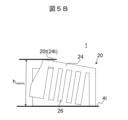
- FIGS. 5A and 5B are schematic diagrams respectively explaining one example and another example of the height of the deformed portion in the method for measuring the amount of deformation of the deformed portion of the additive manufacturing specimen according to the first embodiment.
- the reference portion 10 and the deformation portion 20 which are aligned in the plane direction of the upper surface 2t of the base plate 2, and these are integrated.
- An additional manufacturing test piece 1 having a connecting portion 30 is manufactured on the upper surface 2t of the base plate 2 (manufacturing step S101).
- the reference portion 10 has a rectangular parallelepiped shape, and the connection portion 30 is connected to one end of one side surface 10s of the reference portion 10 on the other adjacent side surface 10s side.
- the deformation portion 20 includes a rectangular parallelepiped cantilever portion 24 extending in a direction parallel to both the surface direction of the upper surface 2t of the base plate 2 and the surface direction of the side surface 10s of the reference portion 10, and the base plate 2 extending from the bottom surface 24b of the cantilever portion 24. and a comb tooth portion 26 extending to the upper surface 2t.
- comb teeth on one end side of the comb tooth portion 26 are connected to side surfaces 30 s of the connecting portion 30 .
- the upper surface 10t of the reference portion 10 and the upper surface 24t of the cantilever portion 24 are parallel to the upper surface 2t of the base plate 2, and the heights (additional The position in the stacking direction (the direction perpendicular to the upper surface 2t of the base plate 2) in manufacturing is the same.
- the top surface 30t of the connecting portion 30 and the bottom surface 24b of the cantilever portion 24 are also parallel to the top surface 2t of the base plate 2, and the heights of these surfaces 30t and 24b with respect to the top surface 2t of the base plate 2 are also the same.
- the bottom surface 10b of the reference portion 10 the bottom surface 26b of the comb tooth portion 26 of the deformation portion 20 (the bottom surface 20b of the deformation portion 20), and the bottom surface 30b of the connection portion 30 are added so as to be joined to the top surface 2t of the base plate 2.
- a production specimen 1 is produced.
- the ratio of the horizontal Xr to the vertical Yr (aspect ratio (Xr/Yr)) of the rectangular parallelepiped reference portion 10 as shown in FIG. 3A is 3/4 or more and 5/4 or less. Therefore, as shown in FIG. 3B, the bending ratio of the reference portion 10 due to the residual stress is 1% or less.
- the ratio of bending due to the residual stress of the reference portion 10 is defined so that the bottom surface 10b of the reference portion 10 is joined to the upper surface 2t of the base plate 2 by performing additional manufacturing under the predetermined conditions using the metal powder.
- the portion 10 When the portion 10 is manufactured alone on the upper surface 2t of the base plate 2, and the reference portion 10 is completely separated from the upper surface 2t of the base plate 2 after the heating and cooling processes in the additive manufacturing are completed and the reference portion 10 reaches room temperature.
- the ratio of the bending due to the residual stress of the reference part 10 that has been cut off which is the ratio of the difference between the height after separation and the height before separation to the height before separation ((height after separation - height before separation) / height before separation) point to
- the “height before cutting” refers to the dimension in the direction perpendicular to the top surface of the base plate at the reference portion before cutting from the top surface of the base plate
- the “height after cutting” refers to the dimension after cutting from the top surface of the base plate.
- the length Ym of the rectangular parallelepiped cantilever portion 24 of the deformation portion 20 as shown in FIG.
- the ratio (aspect ratio (Xm/Ym)) of the lateral Xm (the length of the cantilever portion 24 in the extending direction) to 5/4 is greater than 5/4. Therefore, as shown in FIG. 3B, the ratio of bending due to residual stress in the cantilever portion 24 is greater than 1%.
- the bending ratio of the cantilever portion 24 due to the residual stress means that the cantilever portion 24 is bent so that the bottom surface 24b of the cantilever portion 24 is joined to the top surface 2t of the base plate 2 by performing additional manufacturing under the above-described predetermined conditions using the above-described metal powder.
- the portion 24 is manufactured alone on the top surface 2t of the base plate 2, and the cantilever portion 24 is completely cut off from the top surface 2t of the base plate 2 after the heating and cooling processes in the additive manufacturing are finished and the temperature reaches room temperature, the cantilever portion 24 is cut off.
- the “height before separation” refers to the dimension of the cantilever portion in the direction perpendicular to the top surface of the base plate before being separated from the top surface of the base plate
- the “height after separation” is the height after separation from the top surface of the base plate. It refers to the dimension in the same direction as the vertical direction in the cantilever portion after deformation due to the residual stress after the deformation.
- the thickness Tm of the cantilever portion 24 takes a value between the thickness of one material layer added when manufacturing the additional manufacturing test piece 1 and the height of the deformation portion 20 .
- a specific value of the thickness Tm of the cantilever portion 24 is appropriately determined depending on the manufacturing material and the accuracy of a measuring device used for measuring the amount of deformation of the deformation portion 20, which will be described later.
- the thickness Tm of the cantilever portion 24 is obtained by measuring the deformation amount of the cantilever portion 24 (the deformation amount of the deformable portion 20) under the condition that the cantilever portion 24 is not broken by stress or heat generated during manufacturing, and the measuring device. determined by the conditions under which it is possible.
- the thickness Tm of the cantilever portion 24 The greater the thickness Tm of the cantilever portion 24, the less likely it is to be broken. Therefore, the lower limit of Tm is determined by the material of manufacture, and the upper limit of Tm is determined by the measurement equipment.
- the thickness Tm of the cantilever portion 24 1.0 mm can be used when the manufacturing material is stainless steel 316L.
- the additive manufacturing test piece 1 is separated from the upper surface 2t of the base plate 2 after the heating and cooling processes in the additive manufacturing are completed and the temperature reaches room temperature (separating step S102).
- the bottom surface 10b of the reference portion 10 the bottom surface 26b of the comb tooth portion 26 of the deformable portion 20 (the bottom surface 20b of the deformable portion 20), and the bottom surface 30b of the connecting portion 30 are separated from the base plate by a cutting method such as wire cutting.
- the additive manufacturing specimen 1 is completely cut off from the top surface 2t of the base plate 2 so that the top surface 2t of the base plate 2 is completely cut off.
- the additional manufacturing specimen 1 separated from the top surface 2t of the base plate 2 is installed on the installation plane 4t so that the bottom surface 10b of the reference portion 10 is in close contact with the installation plane 4t, as shown in FIGS. 4A to 5B.
- the cantilever portion 24 of the deformation portion 20 has an aspect ratio (Xm/Ym) greater than 5/4, the residual stress accumulated in the additive manufacturing process causes the free end position to become the solid end position. It bends greatly upward so that it is higher than the The comb tooth portion 26 of the deformation portion 20 is also deformed according to the cantilever portion 24 .
- the reference portion 10 has an aspect ratio (Xr/Yr) of 3/4 or more and 5/4 or less, the residual stress influences the deformation of the cantilever portion 24 to a negligible degree. only not deformed.
- the height hmeans of the deformation portion 20 is measured as the deformation amount of the deformed portion 20 of the additional manufacturing specimen 1 (measurement step S103). That is, the difference between the height h ref of the reference portion 10 and the height h mean of the deformation portion 20 is measured as the amount of deformation of the deformation portion 20 of the additional manufacturing specimen 1 .
- the height h ref of the reference portion 10 is the height of the upper surface 10t of the reference portion 10 with respect to the installation plane 4t on which the reference portion 10 is installed (the stacking direction in additive manufacturing (to the installation plane position) in the vertical direction).
- the height h ref of the reference portion 10 may be the average height h ref,avg of a part or the entire area of the upper surface 10t of the reference portion 10, as shown in FIG. 4A.
- the average height h ref,avg of part or the entire area of the top surface 10t of the reference section 10 is, for example, the height of the part or the entire area of the top surface 10t of the reference section 10, as expressed by the formula shown in FIG.
- the height h ref of the reference portion 10 may be the height h ref at one position on the upper surface 10t of the reference portion 10, as shown in FIG. 4B.
- the height h means of the deformation portion 20 is the height of the upper surface 20t of the deformation portion 20 with respect to the installation plane 4t on which the reference portion 10 is installed (position in the stacking direction in additive manufacturing). be.
- the height h means of the deforming portion 20 may be the height at one position of the upper surface 20t of the deforming portion 20 (the upper surface 24t of the cantilever portion 24), as shown in FIG. 5A.
- the height h means of the deformation portion 20 may be the average height of a part or the entire region of the upper surface 20t of the deformation portion 20, although not shown.
- the average height of a part or the entire area of the upper surface 20t of the deformation section 20 can be calculated, for example, as the average of the heights of the positions of the part or the entire area of the upper surface 20t of the deformation section 20 in the two-dimensional coordinate system.
- the height h means of the deforming portion 20 may be the maximum height h means of the upper surface 20t of the deforming portion 20, as shown in FIG. 5B.
- the amount of deformation due to the residual stress of the additional manufacturing test piece 1 manufactured on the upper surface 2t of the base plate 2 is the deformation based on the height h ref of the reference portion 10 in the additional manufacturing test piece 1 separated from the deformation portion 20.
- the height h means of the portion 20 (the amount of deformation of the deformable portion 20 with respect to the reference portion 10) can be measured.
- the additive manufacturing test in which the base plate is manufactured by performing the additive manufacturing using the metal powder As the amount of deformation due to the residual stress of the body, the amount of deformation of the deformed portion can be measured with reference to the reference portion of the additional manufacturing test piece separated from the base plate. This makes it possible to accurately evaluate the deformation of the additional manufacturing test piece due to the residual stress while the additional manufacturing test piece is separated from the base plate.
- additive manufacturing specimens may be manufactured continuously on the baseplate, even if the additive manufacturing specimen is stored for remeasurement of deformation or for direct comparison with another additive manufacturing specimen. can do.
- the base plate has a reference part and a deformed part lined up in the plane direction of the upper surface of the base plate, and an additional part that integrates these parts.
- a production specimen is manufactured on the upper surface of the base plate such that the reference portion, the deformation portion and the connection portion are bonded to the upper surface of the base plate.
- the additive manufacturing metal powder is not particularly limited, but for example, stainless steel powder, carbon steel powder, alloy tool steel powder, Ni-based alloy powder, Ti-based alloy powder, aluminum alloy powder, copper alloy powder, etc. Powder etc. are mentioned.
- the conditions for additive manufacturing are not particularly limited, but for example, the type of heat source such as laser light or electron beam (hereinafter sometimes simply referred to as "heat source”), the power input to the heat source, and the metal powder.
- the diameter of the heat source when the shape is represented by a circle (spot size), the speed at which the heat source is scanned over the metal powder (scan speed), the interval at which the heat source is scanned over the metal powder (hatch distance), and the metal powder is stacked One layer thickness etc. can be mentioned.
- performing additive manufacturing using metal powder under predetermined conditions means, for example, performing additive manufacturing using these conditions as predetermined conditions.
- FIGS. 6(a), (c), and (e) are schematic perspective views showing an example of an additive manufacturing test body manufactured in the manufacturing process according to the embodiment
- FIGS. ) and (f) are schematic side views of the additive manufacturing test bodies shown in FIGS. 6(a), (c) and (e), respectively.
- the additional manufacturing specimen 1 shown in FIGS. 6(a) and (b) is the same as the additional manufacturing specimen 1 shown in FIGS. 2(a) and (b).
- the additive manufacturing test piece 1 shown in FIGS. The reference portion 10 has a rectangular parallelepiped shape, and the four connection portions 30 are connected to one end of each of the four side surfaces 10s of the reference portion 10 on the side adjacent to each other.
- the four deformation portions 20 include a rectangular parallelepiped cantilever portion 24 extending in a direction parallel to both the surface direction of the upper surface (not shown) of the base plate and the surface direction of the side surface 10s of the reference portion 10, and the bottom surface of the cantilever portion 24. and comb teeth 26 extending from 24b to the top surface of the base plate (not shown).
- the four deformation portions 20 are connected to the side surfaces 30 s of the four connection portions 30 at the comb teeth on one end side of the comb tooth portions 26 (one end of the deformation portion 20 ).
- the reference portion 10 has a rectangular parallelepiped shape, and the connection portion 30 is connected to one side surface 10 s of the reference portion 10 .
- the deformation portion 20 includes a rectangular parallelepiped cantilever portion 24 extending in a direction perpendicular to one side surface 10s of the reference portion 10, and a comb tooth portion extending from the bottom surface 24b of the cantilever portion 24 to the top surface (not shown) of the base plate. 26.
- comb teeth on one end side of the comb tooth portion 26 are connected to side surfaces 30 s of the connecting portion 30 .
- the manufacturing process is not particularly limited as long as it is a process for manufacturing the additional manufacturing test piece on the upper surface of the base plate. 6(a), (c), and (e), the manufacturing process includes one or more of the reference portions, one or more of the deformation portions, and one or more may be a step of manufacturing the additive manufacturing test piece having the connecting portion of
- the process of spreading a layer of metal powder on the upper surface of the base plate and the process of melting only the region corresponding to the additional manufacturing test body in the single layer of metal powder with a heat source and integrating the powder bed are repeated. It is a process according to the powder bed fusion method.
- the metal powder is spread on the upper surface of the base plate, and the bottom layer of the additive manufacturing specimen is joined with the base plate in the process of fusion and integration by a heat source.
- the process according to the powder bed fusion method is an example of the manufacturing process, and the manufacturing process is not limited to the process according to the powder bed fusion method.
- a process according to the Direct Energy Deposition method for example, a process according to the Binder Jet method, or the like can be used. Since these additive manufacturing methods (additional molding methods) are well-known techniques, detailed description thereof will be omitted.
- the manufacturing process may be a process of manufacturing the rectangular parallelepiped reference part like the reference part shown in FIGS. 6(a), (c), and (e).
- the manufacturing process is preferably a process of manufacturing the reference portion in which deformation due to residual stress caused by additive manufacturing is as small as possible.
- the metal powder is a metal powder such as a powder of stainless steel
- the manufacturing process should be such that the ratio of the width to the length (aspect ratio (Xr /Yr)) is preferably 3/4 or more and 5/4 or less. This is because the deformation of the reference portion due to residual stress is reduced, and the amount of deformation of the deformed portion can be accurately measured with the reference portion as a reference in the measurement process.
- the cantilever portion extending in the plane direction on the upper surface of the base plate, and the base plate extending from the bottom surface of the cantilever portion. It is preferable to manufacture the deformation portion including a comb tooth portion extending to the upper surface and having one end connected to the connection portion.
- the manufacturing process is preferably a process of manufacturing the cantilever portion in which the deformation due to the residual stress generated in the additive manufacturing is large enough to reliably measure the amount of deformation in the measuring process.
- the manufacturing process is such that the ratio of the length in the stretching direction to the width (aspect ratio (Xm/Ym)) is 5/
- the process of manufacturing said cantilever portion greater than 4 is preferred. This is because the deformation of the cantilever portion due to residual stress is increased, and the amount of deformation of the deformed portion can be reliably measured with reference to the reference portion in the measurement process.
- the manufacturing process may be a process of manufacturing the additive manufacturing test body in which the upper surface of the reference portion and the upper surface of the cantilever portion are parallel to the upper surface of the base plate.
- the heights of the upper surface of the reference portion and the upper surface of the cantilever portion with respect to the upper surface of the base plate are the same. It may be a step of manufacturing an additive manufacturing specimen.
- shape and aspect ratio (Xr/Yr) of the reference portion manufactured in the manufacturing process the shape and aspect ratio (Xm/Ym) of the deformable portion manufactured in the manufacturing process, and the shape and aspect ratio (Xm/Ym) of the cantilever portion manufactured in the manufacturing process
- the shape of the additive manufacturing test piece means that after the heating and cooling processes in the additive manufacturing are completed and the additive manufacturing test piece reaches room temperature, the additive manufacturing test piece is removed from the upper surface of the base plate in a separation step. refers to the one before it is separated.
- the additive manufacturing specimen is separated from the upper surface of the base plate.
- the additive manufacturing specimen is typically detached from the top surface of the baseplate after the additive manufacturing heating and cooling processes have been completed and the additive manufacturing specimen has reached room temperature.
- the additional manufacturing specimen may be completely separated from the top surface of the base plate so that the reference portion, the deforming portion and the connecting portion are completely separated from the top surface of the base plate.
- the additive manufacturing specimen may be partially detached from the top surface of the base plate so as to be completely detached from the base plate.
- the method of separating the additive manufacturing specimen from the upper surface of the base plate is not particularly limited, but examples include cutting methods such as wire cutting.
- each region of the entire additive product (additive product), such as an additive manufacturing test specimen, shall comply with the conditions of additive manufacturing. Varying degrees of expansion and contraction of the material can occur accordingly.
- the shape of the additive product may be as intended immediately after additive manufacturing, but there may be a local region that expands once and shrinks as the temperature normalizes. and expand as the temperature normalizes. Thus, the additive product will have tensile stresses in some localized areas and compressive stresses in other localized areas at the same time. These stresses are known as so-called "residual stresses”.
- metal powders in the case of very ductile metal powders such as aluminum alloys and copper alloys, deformation of the additional product may occur immediately due to residual stress as the temperature of the material normalizes. Even with other metal powders, the add-on product may simply crack under pressure, depending on the balance of internal tension, internal compression, external loading, and surface tension of the add-on product. Such cracking occurs when all internal stresses in the additive product exceed the yield stress, and can occur even in the case of less ductile metal powders such as some alloyed tool steels.
- the internal tension, internal compression, external load, and surface tension of the additive product may be perfectly balanced.
- the state of the additive product can be conditionally stable.
- the load of the additive product is unbalanced, the condition of the additive product can quickly become unstable.
- the deformation can lead to immediate cracking.
- the additive manufacturing specimen separated from the top surface of the base plate deforms due to the residual stress accumulated in the additive manufacturing process. Therefore, it is possible to measure the amount of deformation of the deformed portion with reference to the reference portion in the measurement process to be described later.
- the amount of deformation of the deformed portion is measured with respect to the reference portion in the additional manufacturing specimen separated from the upper surface of the base plate.
- the measuring step is not particularly limited as long as it is a step of measuring the amount of deformation.
- a step of measuring the amount of change in the dimensional difference between the reference portion and the deformed portion as the amount of deformation is preferable. measuring the amount of change in the dimensional difference between the reference portion and the deformed portion as the amount of deformation, and in particular, measuring the amount of change in the dimensional difference between the reference portion and the deformed portion along the direction of deformation as the amount of deformation.
- the measuring step of measuring as the amount of deformation, the amount of change in the dimensional difference between the reference portion and the deformation portion along the deformation direction of the measuring body, for example, A step of measuring the amount of change in height as the amount of deformation is preferable, and among others, a step of measuring the height of the deformed portion based on the height of the reference portion as the amount of deformation as in the first embodiment is preferable.
- the height of the reference portion may be, for example, the height of one position on the upper surface of the reference portion or the average of the heights of a plurality of positions, as shown in FIGS. 4A and 4B.
- the height of the deformation may be, for example, the height of one position on the upper surface of the deformation or the average of the heights of a plurality of positions, as shown in FIGS. 5A and 5B.
- the height of the deformation portion may be the maximum height of the upper surface of the deformation portion, as shown in FIG. 5B. Note that the height direction usually coincides with the stacking direction in additive manufacturing.
- the manufacturing process is a process of manufacturing a plurality of the reference portions or a plurality of the deformed portions
- a plurality of Measure the difference between the sum of the dimensions of the reference portion and the sum of the dimensions of the plurality of deformed portions, or the difference between the average of the dimensions of the plurality of reference portions and the average of the dimensions of the plurality of deformed portions, as the amount of deformation may Further, in this case, the maximum difference among the differences in the dimensions of the reference portion and the deformation portion in a plurality of combinations of the reference portion and the deformation portion may be measured as the amount of deformation. may be measured as the amount of deformation, or an intermediate difference between them may be measured as the amount of deformation.
- the method of measuring the amount of deformation of the deformed part is a method of measuring the amount of deformation of the deformed part of the additive manufacturing specimen manufactured on the upper surface of the base plate by performing additive manufacturing using metal powder. and includes the manufacturing process, the separating process, and the measuring process.
- Method for Determining Appropriate Conditions for Additive Manufacturing Using Method for Measuring Deformation Amount of Deformed Part of Additive Manufacturing Specimen Using a method for measuring the deformation of the deformed portion, a measurement step of measuring the deformation of the deformed portion, and, for example, using at least one of design of experiments and regression analysis, from the predetermined condition and the deformation and a determining step of determining the appropriate conditions for additive manufacturing.
- the method for measuring the amount of deformation of the deformed portion of the additive manufacturing specimen according to the embodiment described above is used a plurality of times.
- a plurality of additional manufacturing test specimens are manufactured, and multiple sets of reference parts and deformed parts possessed by each of the plurality of additional manufacturing test specimens
- the amount of deformation of the deformed portion is measured on the basis of the portion.
- a plurality of sets of teaching data are prepared, with the predetermined condition of additive manufacturing as the explanatory variable and the deformation amount of the deformed portion with reference to the reference portion as the objective variable.
- the method of separating the additional manufacturing test piece from the upper surface of the base plate may be unified. Also, the parts of the additional manufacturing specimen that are cut off from the upper surface of the base plate may be unified. Furthermore, the direction and processing of separating the additive manufacturing specimen from the upper surface of the base plate may be unified.
- constructing a predictive model simplify the process of constructing a predictive model by following known trends derived from analytical or numerical models described in the literature or obtained from experiments or simulations, or from underlying physics and mathematics. can be
- FIG. 7 is a flowchart showing a method for determining appropriate conditions for additive manufacturing according to the second embodiment.
- the method for determining appropriate conditions for additive manufacturing according to the second embodiment is a method for determining appropriate conditions for additive manufacturing when performing additive manufacturing using metal powder.
- setting conditions for additive manufacturing are set to predetermined conditions (setting step S201).
- the top surface of the base plate is An additional manufacturing specimen having a reference portion and a deformation portion arranged in a plane direction and a connection portion for integrating them is attached to the base plate so that the reference portion, the deformation portion and the connection portion are joined to the upper surface of the base plate. It is manufactured on the upper surface (manufacturing step S202).
- the additional manufacturing specimen is separated from the upper surface of the base plate (separating step S203).
- the height hmeans of the deformation portion (the height hmeans of the reference portion) based on the height href of the reference portion is measured (measuring step S204).
- the experimental design and from the deformation height h means relative to the set conditions of the additive manufacturing and the reference height h ref measured in the measuring step S204, by using at least one regression analysis, A correction condition for the additive manufacturing is obtained, which is estimated to make the height hmeans of the deformed portion based on the height href of the reference portion equal to or less than a predetermined value (optimization step S205).
- the condition of additive manufacturing when additive manufacturing is performed using a known metal powder is used as an explanatory variable, and the height hmeans of the deformed portion is based on the height href of the reference portion in that case .
- the measurement step S204 Select a predictive model that can predict the deformation height hmeans relative to the reference height href measured at .
- the selected predictive model when the additive manufacturing is performed using the powder of stainless steel 316L (metallic powder), the height of the deformed portion based on the height h ref of the reference portion Obtain a modification condition for the additive manufacturing that is estimated to be less than or equal to a predetermined value of h_means .
- the appropriate conditions for the additional manufacturing are determined as the set conditions for the additional manufacturing (determining step S206). After the determination step S206, the method for determining appropriate conditions for additive manufacturing according to the second embodiment ends.
- the setting step S201 and the The manufacturing step S202, the separating step S203, the measuring step S204, and the optimizing step S205 are repeated in this order.
- the manufacturing correction conditions are set to the predetermined conditions.
- the setting conditions for additive manufacturing are set to predetermined conditions.
- the initial condition to be set to the predetermined condition in the initial setting step is not particularly limited, but may be any condition in the additive manufacturing condition list designed to measure the limits of the metal powder used in additive manufacturing. Also, the initial conditions may be conditions defined or accepted as appropriate conditions for additive manufacturing of known metal powders.
- the additive manufacturing correction conditions obtained in the optimization step are set to the predetermined conditions.
- the embodiments have been described with reference to the drawings, etc., but the present invention is not limited to the embodiments. Anything that has the same function and effect is included in the technical scope of the present invention, and various modifications are included.
- the embodiments are described in detail in order to explain the present invention in an easy-to-understand manner, and are not necessarily limited to those having all the described configurations.
- part of the configuration of one embodiment can be replaced with the configuration of another embodiment, and the configuration of another embodiment can be added to the configuration of one embodiment.
Landscapes
- Engineering & Computer Science (AREA)
- Chemical & Material Sciences (AREA)
- Materials Engineering (AREA)
- Manufacturing & Machinery (AREA)
- Automation & Control Theory (AREA)
- Physics & Mathematics (AREA)
- Plasma & Fusion (AREA)
- Powder Metallurgy (AREA)
- Sampling And Sample Adjustment (AREA)
Priority Applications (3)
| Application Number | Priority Date | Filing Date | Title |
|---|---|---|---|
| JP2023554705A JPWO2023068268A1 (https=) | 2021-10-19 | 2022-10-18 | |
| EP22883572.4A EP4420812A1 (en) | 2021-10-19 | 2022-10-18 | Method for measuring deformation amount of deformation part of additively fabricated test object and method for determining proper conditions for additive fabrication |
| US18/690,318 US20240335879A1 (en) | 2021-10-19 | 2022-10-18 | Method for measuring deformation amount of deformation part of additively manufactured test object and method for determining optimum condition for additive manufacturing |
Applications Claiming Priority (2)
| Application Number | Priority Date | Filing Date | Title |
|---|---|---|---|
| JP2021-171182 | 2021-10-19 | ||
| JP2021171182 | 2021-10-19 |
Publications (1)
| Publication Number | Publication Date |
|---|---|
| WO2023068268A1 true WO2023068268A1 (ja) | 2023-04-27 |
Family
ID=86059156
Family Applications (1)
| Application Number | Title | Priority Date | Filing Date |
|---|---|---|---|
| PCT/JP2022/038762 Ceased WO2023068268A1 (ja) | 2021-10-19 | 2022-10-18 | 付加製造試験体の変形部の変形量の測定方法及び付加製造の適正条件の決定方法 |
Country Status (4)
| Country | Link |
|---|---|
| US (1) | US20240335879A1 (https=) |
| EP (1) | EP4420812A1 (https=) |
| JP (1) | JPWO2023068268A1 (https=) |
| WO (1) | WO2023068268A1 (https=) |
Cited By (1)
| Publication number | Priority date | Publication date | Assignee | Title |
|---|---|---|---|---|
| EP4509248A3 (en) * | 2023-08-17 | 2025-03-19 | Proterial, Ltd. | Crack evaluation method of additively manufactured object and crack evaluation device |
Citations (6)
| Publication number | Priority date | Publication date | Assignee | Title |
|---|---|---|---|---|
| US20190377843A1 (en) * | 2018-06-06 | 2019-12-12 | Hamilton Sundstrand Corporation | Additive manufacturing including compensation modeling methodology with shape transformation |
| EP3587005A1 (en) * | 2018-06-26 | 2020-01-01 | Siemens Aktiengesellschaft | Control method for layerwise additive manufacturing, computer program product and control apparatus |
| WO2020176283A1 (en) | 2019-02-25 | 2020-09-03 | General Electric Company | Transfer learning/dictionary generation and usage for tailored part parameter generation from coupon builds |
| WO2020191263A1 (en) | 2019-03-21 | 2020-09-24 | General Electric Company | In-situ monitoring system assisted material and parameter development for additive manufacturing |
| JP2021016885A (ja) * | 2019-07-19 | 2021-02-15 | 株式会社神戸製鋼所 | 積層造形物の積層計画方法、積層造形物の製造方法及び製造装置 |
| JP2021171182A (ja) | 2020-04-21 | 2021-11-01 | 株式会社ユニバーサルエンターテインメント | 遊技機 |
Family Cites Families (6)
| Publication number | Priority date | Publication date | Assignee | Title |
|---|---|---|---|---|
| ES2983485T3 (es) * | 2015-11-16 | 2024-10-23 | Renishaw Plc | Método y aparato de fabricación aditiva |
| US10549478B2 (en) * | 2016-02-11 | 2020-02-04 | General Electric Company | Methods and surrounding supports for additive manufacturing |
| US10471695B2 (en) * | 2016-10-26 | 2019-11-12 | General Electric Company | Methods and thermal structures for additive manufacturing |
| US10545806B2 (en) * | 2017-06-05 | 2020-01-28 | International Business Machines Corporation | Proximity correction in three-dimensional manufacturing |
| DE102021103739A1 (de) * | 2021-02-17 | 2022-08-18 | Te Connectivity Germany Gmbh | Additives Fertigungssystem mit einer Mehrzahl von Fertigungsstationen und Verfahren zur additiven Fertigung einer Mehrzahl von Werkstücken |
| EP4170537B1 (en) * | 2021-10-20 | 2025-04-23 | General Electric Company | Systems and methods to improve the accuracy and manufacturability in an additive manufacturing compensation process |
-
2022
- 2022-10-18 JP JP2023554705A patent/JPWO2023068268A1/ja active Pending
- 2022-10-18 EP EP22883572.4A patent/EP4420812A1/en not_active Withdrawn
- 2022-10-18 WO PCT/JP2022/038762 patent/WO2023068268A1/ja not_active Ceased
- 2022-10-18 US US18/690,318 patent/US20240335879A1/en active Pending
Patent Citations (6)
| Publication number | Priority date | Publication date | Assignee | Title |
|---|---|---|---|---|
| US20190377843A1 (en) * | 2018-06-06 | 2019-12-12 | Hamilton Sundstrand Corporation | Additive manufacturing including compensation modeling methodology with shape transformation |
| EP3587005A1 (en) * | 2018-06-26 | 2020-01-01 | Siemens Aktiengesellschaft | Control method for layerwise additive manufacturing, computer program product and control apparatus |
| WO2020176283A1 (en) | 2019-02-25 | 2020-09-03 | General Electric Company | Transfer learning/dictionary generation and usage for tailored part parameter generation from coupon builds |
| WO2020191263A1 (en) | 2019-03-21 | 2020-09-24 | General Electric Company | In-situ monitoring system assisted material and parameter development for additive manufacturing |
| JP2021016885A (ja) * | 2019-07-19 | 2021-02-15 | 株式会社神戸製鋼所 | 積層造形物の積層計画方法、積層造形物の製造方法及び製造装置 |
| JP2021171182A (ja) | 2020-04-21 | 2021-11-01 | 株式会社ユニバーサルエンターテインメント | 遊技機 |
Non-Patent Citations (3)
| Title |
|---|
| CRUISE, R. ET AL.: "Residual stress analysis of structural stainless steel sections", JOURNAL OF CONSTRUCTIONAL STEEL RESEARCH, vol. 64, 2008, pages 3, XP022482887, DOI: 10.1016/j.jcsr.2007.08.001 |
| GIBSON, I. ET AL.: "Additive manufacturing technologies", 2014, SPRINGER |
| LI, C. ET AL.: "Efficient multiscale prediction of cantilever distortion by selective laser melting", PROC. 27TH ANNU. INT. SOLID FREE. FABR. SYMP, 2016 |
Cited By (1)
| Publication number | Priority date | Publication date | Assignee | Title |
|---|---|---|---|---|
| EP4509248A3 (en) * | 2023-08-17 | 2025-03-19 | Proterial, Ltd. | Crack evaluation method of additively manufactured object and crack evaluation device |
Also Published As
| Publication number | Publication date |
|---|---|
| JPWO2023068268A1 (https=) | 2023-04-27 |
| EP4420812A1 (en) | 2024-08-28 |
| US20240335879A1 (en) | 2024-10-10 |
Similar Documents
| Publication | Publication Date | Title |
|---|---|---|
| De Baere et al. | Thermo-mechanical modelling of stress relief heat treatments after laser-based powder bed fusion | |
| JP6380536B2 (ja) | モデル設定方法、成形シミュレーション方法、プログラム、及びプログラムを記録したコンピュータ読み取り可能な記録媒体 | |
| JP6547763B2 (ja) | スプリングバック量予測方法 | |
| Kim et al. | Analysis of residual stress evolution during powder bed fusionprocess of AISI 316L stainless steel with experiment and numerical modeling | |
| JP5063768B2 (ja) | 変形推定方法、プログラムおよび記録媒体 | |
| Yao et al. | Analysis of shell cracking in investment casting with laser stereolithography patterns | |
| CN119203680B (zh) | 金属塑料复合制品加工中热变形预测与优化方法和系统 | |
| Lu et al. | 3D die shape optimisation for net-shape forging of aerofoil blades | |
| CN118797914A (zh) | 一种用于金属增材制造残余应力与变形预测的动态固有应变方法 | |
| Van Driel et al. | Response surface modeling for nonlinear packaging stresses | |
| WO2023068268A1 (ja) | 付加製造試験体の変形部の変形量の測定方法及び付加製造の適正条件の決定方法 | |
| Terrenoir et al. | Influence of wire feed speed and torch speed on the mechanical properties of wire arc additively manufactured stainless steel | |
| Vatani et al. | Distortion modeling of SL parts by classical lamination theory | |
| Socrate et al. | A finite element based die design algorithm for sheet-metal forming on reconfigurable tools | |
| Douellou et al. | Assessment of geometrical defects caused by thermal distortions in laser-beam-melting additive manufacturing: a simulation approach | |
| JP3978377B2 (ja) | 成形シミュレーション解析方法 | |
| Psihoyos et al. | Efficient thermomechanical modelling of Laser Powder Bed Fusion additive manufacturing process with emphasis on parts residual stress fields. | |
| Mikihito et al. | A simplified FE simulation method with shell element for welding deformation and residual stress generated by multi-pass butt welding | |
| Henrard et al. | Comparison of FEM simulations for the incremental forming process | |
| Park et al. | Development of a prediction system for 3D printed part deformation | |
| JP2006000879A (ja) | 変形推定方法、プログラムおよび記録媒体 | |
| Li et al. | Identification of material parameters from punch stretch test | |
| Saravanan et al. | Study on effects of spring back on sheet metal bending using simulation methods | |
| Brezmes et al. | Mechanical analysis of wafer testing with FEM simulations | |
| Zhang et al. | Comparative study of various hardening models for the prediction of plastic responses under strain path change conditions |
Legal Events
| Date | Code | Title | Description |
|---|---|---|---|
| 121 | Ep: the epo has been informed by wipo that ep was designated in this application |
Ref document number: 22883572 Country of ref document: EP Kind code of ref document: A1 |
|
| WWE | Wipo information: entry into national phase |
Ref document number: 2023554705 Country of ref document: JP |
|
| WWE | Wipo information: entry into national phase |
Ref document number: 18690318 Country of ref document: US |
|
| WWE | Wipo information: entry into national phase |
Ref document number: 2022883572 Country of ref document: EP |
|
| NENP | Non-entry into the national phase |
Ref country code: DE |
|
| ENP | Entry into the national phase |
Ref document number: 2022883572 Country of ref document: EP Effective date: 20240521 |
|
| WWW | Wipo information: withdrawn in national office |
Ref document number: 2022883572 Country of ref document: EP |