EP4420812A1 - Method for measuring deformation amount of deformation part of additively fabricated test object and method for determining proper conditions for additive fabrication - Google Patents
Method for measuring deformation amount of deformation part of additively fabricated test object and method for determining proper conditions for additive fabrication Download PDFInfo
- Publication number
- EP4420812A1 EP4420812A1 EP22883572.4A EP22883572A EP4420812A1 EP 4420812 A1 EP4420812 A1 EP 4420812A1 EP 22883572 A EP22883572 A EP 22883572A EP 4420812 A1 EP4420812 A1 EP 4420812A1
- Authority
- EP
- European Patent Office
- Prior art keywords
- deformation
- test object
- additively manufactured
- baseplate
- manufactured test
- Prior art date
- Legal status (The legal status is an assumption and is not a legal conclusion. Google has not performed a legal analysis and makes no representation as to the accuracy of the status listed.)
- Withdrawn
Links
Images






Classifications
-
- B—PERFORMING OPERATIONS; TRANSPORTING
- B33—ADDITIVE MANUFACTURING TECHNOLOGY
- B33Y—ADDITIVE MANUFACTURING, i.e. MANUFACTURING OF THREE-DIMENSIONAL [3D] OBJECTS BY ADDITIVE DEPOSITION, ADDITIVE AGGLOMERATION OR ADDITIVE LAYERING, e.g. BY 3D PRINTING, STEREOLITHOGRAPHY OR SELECTIVE LASER SINTERING
- B33Y10/00—Processes of additive manufacturing
-
- B—PERFORMING OPERATIONS; TRANSPORTING
- B22—CASTING; POWDER METALLURGY
- B22F—WORKING METALLIC POWDER; MANUFACTURE OF ARTICLES FROM METALLIC POWDER; MAKING METALLIC POWDER; APPARATUS OR DEVICES SPECIALLY ADAPTED FOR METALLIC POWDER
- B22F10/00—Additive manufacturing of workpieces or articles from metallic powder
- B22F10/20—Direct sintering or melting
- B22F10/28—Powder bed fusion, e.g. selective laser melting [SLM] or electron beam melting [EBM]
-
- B—PERFORMING OPERATIONS; TRANSPORTING
- B22—CASTING; POWDER METALLURGY
- B22F—WORKING METALLIC POWDER; MANUFACTURE OF ARTICLES FROM METALLIC POWDER; MAKING METALLIC POWDER; APPARATUS OR DEVICES SPECIALLY ADAPTED FOR METALLIC POWDER
- B22F10/00—Additive manufacturing of workpieces or articles from metallic powder
- B22F10/30—Process control
- B22F10/31—Calibration of process steps or apparatus settings, e.g. before or during manufacturing
-
- B—PERFORMING OPERATIONS; TRANSPORTING
- B22—CASTING; POWDER METALLURGY
- B22F—WORKING METALLIC POWDER; MANUFACTURE OF ARTICLES FROM METALLIC POWDER; MAKING METALLIC POWDER; APPARATUS OR DEVICES SPECIALLY ADAPTED FOR METALLIC POWDER
- B22F10/00—Additive manufacturing of workpieces or articles from metallic powder
- B22F10/80—Data acquisition or data processing
- B22F10/85—Data acquisition or data processing for controlling or regulating additive manufacturing processes
-
- B—PERFORMING OPERATIONS; TRANSPORTING
- B33—ADDITIVE MANUFACTURING TECHNOLOGY
- B33Y—ADDITIVE MANUFACTURING, i.e. MANUFACTURING OF THREE-DIMENSIONAL [3D] OBJECTS BY ADDITIVE DEPOSITION, ADDITIVE AGGLOMERATION OR ADDITIVE LAYERING, e.g. BY 3D PRINTING, STEREOLITHOGRAPHY OR SELECTIVE LASER SINTERING
- B33Y30/00—Apparatus for additive manufacturing; Details thereof or accessories therefor
-
- B—PERFORMING OPERATIONS; TRANSPORTING
- B22—CASTING; POWDER METALLURGY
- B22F—WORKING METALLIC POWDER; MANUFACTURE OF ARTICLES FROM METALLIC POWDER; MAKING METALLIC POWDER; APPARATUS OR DEVICES SPECIALLY ADAPTED FOR METALLIC POWDER
- B22F10/00—Additive manufacturing of workpieces or articles from metallic powder
- B22F10/60—Treatment of workpieces or articles after build-up
- B22F10/66—Treatment of workpieces or articles after build-up by mechanical means
-
- B—PERFORMING OPERATIONS; TRANSPORTING
- B33—ADDITIVE MANUFACTURING TECHNOLOGY
- B33Y—ADDITIVE MANUFACTURING, i.e. MANUFACTURING OF THREE-DIMENSIONAL [3D] OBJECTS BY ADDITIVE DEPOSITION, ADDITIVE AGGLOMERATION OR ADDITIVE LAYERING, e.g. BY 3D PRINTING, STEREOLITHOGRAPHY OR SELECTIVE LASER SINTERING
- B33Y50/00—Data acquisition or data processing for additive manufacturing
- B33Y50/02—Data acquisition or data processing for additive manufacturing for controlling or regulating additive manufacturing processes
-
- B—PERFORMING OPERATIONS; TRANSPORTING
- B33—ADDITIVE MANUFACTURING TECHNOLOGY
- B33Y—ADDITIVE MANUFACTURING, i.e. MANUFACTURING OF THREE-DIMENSIONAL [3D] OBJECTS BY ADDITIVE DEPOSITION, ADDITIVE AGGLOMERATION OR ADDITIVE LAYERING, e.g. BY 3D PRINTING, STEREOLITHOGRAPHY OR SELECTIVE LASER SINTERING
- B33Y80/00—Products made by additive manufacturing
-
- G—PHYSICS
- G06—COMPUTING OR CALCULATING; COUNTING
- G06T—IMAGE DATA PROCESSING OR GENERATION, IN GENERAL
- G06T7/00—Image analysis
- G06T7/0002—Inspection of images, e.g. flaw detection
- G06T7/0004—Industrial image inspection
- G06T7/001—Industrial image inspection using an image reference approach
-
- Y—GENERAL TAGGING OF NEW TECHNOLOGICAL DEVELOPMENTS; GENERAL TAGGING OF CROSS-SECTIONAL TECHNOLOGIES SPANNING OVER SEVERAL SECTIONS OF THE IPC; TECHNICAL SUBJECTS COVERED BY FORMER USPC CROSS-REFERENCE ART COLLECTIONS [XRACs] AND DIGESTS
- Y02—TECHNOLOGIES OR APPLICATIONS FOR MITIGATION OR ADAPTATION AGAINST CLIMATE CHANGE
- Y02P—CLIMATE CHANGE MITIGATION TECHNOLOGIES IN THE PRODUCTION OR PROCESSING OF GOODS
- Y02P10/00—Technologies related to metal processing
- Y02P10/25—Process efficiency
Definitions
- the present invention relates to a method for measuring a deformation amount of a deformation part of an additively manufactured test object manufactured by performing additive manufacturing (additive fabrication) using metal powder and a method for determining an optimum condition for additive manufacturing used when the additive manufacturing is performed using metal powder.
- Non Patent Literature 1 To quantify a degree of the deformation depending on a condition of additive manufacturing, a sample of an additively manufactured object to measure a deformation amount (an additively manufactured test object) is required (Patent Literatures 1 and 2).
- Non Patent Literature 2 In the additive manufacturing process, as described in Non Patent Literature 2, the influence of deformation by residual stress cannot be measured. As described in Non Patent Literature 3, the influence of residual stress usually appears when the additively manufactured object is separated from a baseplate after an additive manufacturing step. In Non Patent Literature 3, using an additively manufactured test object including a deformation part having a cantilever shape, an attempt of measuring an influence of residual stress is performed.
- the deformation part having the cantilever shape at least has an aspect ratio of 2:1 and bending can be quantified.
- the additively manufactured test object is held in a state in which at least a part thereof is mounted on a baseplate for measurement.
- One reason thereof is that when the additively manufactured test object is completely separated, it is difficult to set a reference position of deformation of the additively manufactured test object required for accurate measurement of the deformation due to residual stress of the additively manufactured test object.
- the other one reason that the additively manufactured test object is held to the baseplate is to allow appropriately comparing a different additively manufactured test object.
- wire cut that heats a wire to a temperature exceeding a melting point of a material of the additively manufactured test object and slowly guides the wire at a deformation part to cut the deformation part from the baseplate is used.
- the wire deforms during the cut to result in non-uniform cut and an error of about 1 mm at the maximum occurs at a position of the wire cut, and precise cut by the wire cut is difficult. In view of this, accurately comparing deformation amounts of a plurality of the additively manufactured test objects separated from the baseplate is difficult.
- the baseplate is a thick plate made of a firm material, such as a stainless steel and a carbon steel, and is manufactured to bear a large temperature change and be completely heated without generating a crack or plastic deformation.
- the baseplate used for the additive manufacturing of the additively manufactured test object is cleaned after separated from the additively manufactured test object and is used again for the additive manufacturing of another additively manufactured test object.
- the additively manufactured test object need to be held in a state of being mounted on the baseplate. Therefore, the baseplate on which the additively manufactured test object is manufactured cannot be used for manufacturing of a new additively manufactured test object.
- the present invention has been made in consideration of the problems, and an object is to provide a method for measuring a deformation amount of a deformation part of an additively manufactured test object that allows accurately evaluating deformation due to residual stress of the additively manufactured test object in a state of the additively manufactured test object being separated from a baseplate and a method for determining an optimum condition for additive manufacturing.
- a method for measuring a deformation amount of a deformation part of an additively manufactured test object (additively fabricated test object) of the present invention is a method for measuring the deformation amount of the deformation part of the additively manufactured test object manufactured on an upper surface of a baseplate by performing additive manufacturing (additive fabrication) using metal powder.
- the method comprises: a manufacturing step (fabrication step) of performing the additive manufacturing using the metal powder under a predetermined condition to manufacture the additively manufactured test object including a reference part, a deformation part, and a coupling part integrating the reference part and the deformation part arranged in a surface direction of the upper surface of the baseplate on the upper surface of the baseplate such that the reference part, the deformation part, and the coupling part are joined to the upper surface of the baseplate; a separation step of separating the additively manufactured test object from the upper surface of the baseplate; and a measurement step of measuring the deformation amount of the deformation part based on the reference part of the additively manufactured test object separated from the upper surface of the baseplate.
- the method for measuring the deformation amount of the deformation part of the additively manufactured test object of the present invention allows accurately evaluating deformation due to residual stress of the additively manufactured test object in a state of the additively manufactured test object being separated from the baseplate.
- a method for determining an optimum condition for additive manufacturing of the present invention comprises: a measurement step of using the method for measuring the deformation amount of the deformation part of the additively manufactured test object described above to measure the deformation amount of the deformation part; and a determination step of determining the optimum condition for the additive manufacturing from the predetermined condition and the deformation amount.
- the method for determining the optimum condition for the additive manufacturing of the present invention can determine the optimum condition for the additive manufacturing from a result of accurately evaluating the deformation due to residual stress of the additively manufactured test object in a state of being separated from the baseplate.
- the method for determining an optimum condition for the additive manufacturing (additive fabrication) of the present invention is a method for determining an optimum condition for the additive manufacturing used when the additive manufacturing is performed using metal powder.
- the method comprises: a setting step of setting a setting condition of the additive manufacturing to a predetermined condition; a manufacturing step (fabrication step) of performing the additive manufacturing using the metal powder under the setting condition to manufacture an additively manufactured test object (additively fabricated test object) including a reference part, a deformation part, and a coupling part integrating the reference part and the deformation part arranged in a surface direction of an upper surface of a baseplate on the upper surface of the baseplate such that the reference part, the deformation part, and the coupling part are joined to the upper surface of the baseplate; a separation step of separating the additively manufactured test object from the upper surface of the baseplate; a measurement step of measuring a deformation amount of the deformation part based on the reference part of the additively manufactured test object separated from the upper surface of the base
- the method for determining the optimum condition for the additive manufacturing of the present invention can determine the optimum condition for the additive manufacturing from a result of accurately evaluating the deformation due to residual stress of the additively manufactured test object in a state of being separated from the baseplate.
- the present invention allows accurately evaluating deformation due to residual stress of the additively manufactured test object in a state of the additively manufactured test object being separated from the baseplate.
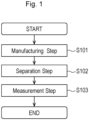
- Fig. 1 is a flowchart depicting the method for measuring the deformation amount of the deformation part of the additively manufactured test object according to the first embodiment.
- Figs. 2A and 2B are a schematic perspective view and a schematic side view each illustrating a manufacturing step in the method for measuring the deformation amount of the deformation part of the additively manufactured test object according to the first embodiment.
- Fig. 1 is a flowchart depicting the method for measuring the deformation amount of the deformation part of the additively manufactured test object according to the first embodiment.
- Figs. 2A and 2B are a schematic perspective view and a schematic side view each illustrating a manufacturing step in the method for measuring the deformation amount of the deformation part of the additively manufactured test object according to the first embodiment.
- Fig. 1 is a flowchart depicting the method for measuring the deformation amount of the deformation part of the additively manufactured test object according to the first embodiment.
- Figs. 2A and 2B are a schematic perspective view and a schematic side
- FIG. 3A is a schematic perspective view illustrating an aspect ratio of a reference part and a cantilever part in the method for measuring the deformation amount of the deformation part of the additively manufactured test object according to the first embodiment.
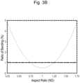
- Fig. 3B is a graph illustrating a ratio of bending to the aspect ratio of the reference part and the cantilever part illustrated in Fig. 3A .
- Figs. 4A and 4B are schematic diagrams each describing an example and another example of a height of the reference part in the method for measuring the deformation amount of the deformation part of the additively manufactured test object according to the first embodiment.
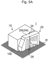
- Figs. 5A and 5B are schematic diagrams each describing an example and another example of a height of the deformation part in the method for measuring the deformation amount of the deformation part of the additively manufactured test object according to the first embodiment.
- an additively manufactured test object 1 including a reference part 10, a deformation part 20, and a coupling part 30 that integrates them is manufactured on the upper surface 2t of the baseplate 2 (a manufacturing step S101).
- the reference part 10, the deformation part 20, and the coupling part 30 are arranged in a surface direction of an upper surface 2t of a baseplate 2.
- the reference part 10 has a rectangular parallelepiped shape, and the coupling part 30 is joined to one end at an adjacent other side surface 10s side in one side surface 10s of the reference part 10.
- the deformation part 20 includes a cantilever part 24 having a rectangular parallelepiped shape extending in a direction parallel to both the surface direction of the upper surface 2t of the baseplate 2 and a surface direction of the side surface 10s of the reference part 10 and a comb teeth part 26 that extends from a bottom surface 24b of the cantilever part 24 to the upper surface 2t of the baseplate 2.
- the deformation part 20 has a comb tooth (one end of the deformation part 20) at one end side of the comb teeth part 26 joined to a side surface 30s of the coupling part 30.
- An upper surface 10t of the reference part 10 and an upper surface 24t of the cantilever part 24 (an upper surface 20t of the deformation part 20) are parallel to the upper surface 2t of the baseplate 2, and heights (positions in a stacking direction in the additive manufacturing (a direction perpendicular to the upper surface 2t of the baseplate 2)) of these upper surfaces 10t, 24t to the upper surface 2t of the baseplate 2 are the same.
- an upper surface 30t of the coupling part 30 and the bottom surface 24b of the cantilever part 24 are also parallel to the upper surface 2t of the baseplate 2, and heights of these surfaces 30t, 24b to the upper surface 2t of the baseplate 2 are the same.
- the additively manufactured test object 1 is manufactured such that a bottom surface 10b of the reference part 10, a bottom surface 26b of the comb teeth part 26 of the deformation part 20 (a bottom surface 20b of the deformation part 20), and a bottom surface 30b of the coupling part 30 are joined to the upper surface 2t of the baseplate 2.
- a ratio of a width Xr to a length Yr of the reference part 10 having the rectangular parallelepiped shape as illustrated in Fig. 3A is 3/4 or more to 5/4 or less.
- a ratio of bending due to residual stress of the reference part 10 becomes 1% or less.
- the ratio of bending due to residual stress of the reference part 10 means the ratio of bending due to residual stress of the separated reference part 10 and a ratio of a difference between a height after separation to a height before separation and the height before separation ((height after separation - height before separation)/height before separation).
- the "height before separation” means a dimension in a direction perpendicular to the upper surface of the baseplate in the reference part before being separated from the upper surface of the baseplate
- the “height after separation” means a dimension in a direction same as the perpendicular direction in the reference part after deformation due to residual stress after being separated from the upper surface of the baseplate.
- the ratio of bending due to residual stress of the cantilever part 24 means the ratio of bending due to residual stress of the separated cantilever part 24 and a ratio of a difference between a height after separation to a height before separation and the height before separation ((height after separation - height before separation)/height before separation).
- the "height before separation” means a dimension in a direction perpendicular to the upper surface of the baseplate in the cantilever part before being separated from the upper surface of the baseplate
- the “height after separation” means a dimension in a direction same as the perpendicular direction in the cantilever part after deformation due to residual stress after being separated from the upper surface of the baseplate.
- a thickness Tm of the cantilever part 24 is a value between a thickness of one layer of a material layer added when the additively manufactured test object 1 is manufactured and the height of the deformation part 20.
- the concrete value of the thickness Tm of the cantilever part 24 is appropriately determined by a raw material and accuracy of a measurement device used to measure a deformation amount of the deformation part 20 described later.
- the thickness Tm of the cantilever part 24 is determined by a condition under which the cantilever part 24 is not broken by stress or heat generated during the manufacturing and a condition under which the deformation amount of the cantilever part 24 (the deformation amount of the deformation part 20) can be measured by the measurement device.
- a lower limit of Tm is determined by the raw material
- an upper limit of Tm is determined by the measurement device.
- the thickness Tm of the cantilever part 24 when the raw material is stainless steel 316L, 1.0 mm can be used.
- the additively manufactured test object 1 is separated from the upper surface 2t of the baseplate 2 (a separation step S102).
- the separation step S 102 for example, by a cutting method, such as wire cut, the additively manufactured test object 1 is completely separated from the upper surface 2t of the baseplate 2 such that the bottom surface 10b of the reference part 10, the bottom surface 26b of the comb teeth part 26 of the deformation part 20 (the bottom surface 20b of the deformation part 20), and the bottom surface 30b of the coupling part 30 are completely separated from the upper surface 2t of the baseplate 2.
- the additively manufactured test object 1 separated from the upper surface 2t of the baseplate 2 is installed on an installation plane 4t such that the bottom surface 10b of the reference part 10 is in close contact with the installation plane 4t.
- the cantilever part 24 of the deformation part 20 has the aspect ratio (Xm/Ym) larger than 5/4, a position of a free end of the cantilever part 24 significantly bends upward so as to be higher than a position of a fixed end of the cantilever part 24 due to residual stress accumulated in the additive manufacturing process.
- the comb teeth part 26 of the deformation part 20 also deforms following the cantilever part 24.
- the reference part 10 since the reference part 10 has the aspect ratio (Xr/Yr) of 3/4 or more to 5/4 or less, regardless of the influence of residual stress, the reference part 10 deforms only by a negligible extent compared with the deformation of the cantilever part 24.
- a height h means of the deformation part 20 based on a height h ref of the reference part 10 is measured as the deformation amount of the deformation part 20 of the additively manufactured test object 1 (a measurement step S103). That is, a difference between the height h ref of the reference part 10 and the height h means of the deformation part 20 is measured as the deformation amount of the deformation part 20 of the additively manufactured test object 1.
- the height h ref of the reference part 10 is a height of the upper surface 10t of the reference part 10 with respect to the installation plane 4t where the reference part 10 is installed (a position in the stacking direction in the additive manufacturing (a direction perpendicular to the installation plane)).
- the height h ref of the reference part 10 may be an average height h ref,avg in a part or the entire region of the upper surface 10t of the reference part 10. As expressed in the formula shown in Fig.
- the average height h ref,avg in a part or the entire region of the upper surface 10t of the reference part 10 can be calculated as the average of the heights h ref (m, n) at respective positions of a two-dimensional coordinate system (mn coordinate system) of a part or the entire region of the upper surface 10t of the reference part 10.
- the height h ref of the reference part 10 may be the height h ref at one position of the upper surface 10t of the reference part 10.
- the height h means of the deformation part 20 is a height of the upper surface 20t of the deformation part 20 with respect to the installation plane 4t where the reference part 10 is installed (a position in the stacking direction in the additive manufacturing).
- the height h means of the deformation part 20 may be a height at one position of the upper surface 20t of the deformation part 20 (the upper surface 24t of the cantilever part 24).
- the height h means of the deformation part 20 may be an average height of a part or the entire region of the upper surface 20t of the deformation part 20.
- the average height of a part or the entire region of the upper surface 20t of the deformation part 20 can be calculated as an average of heights at respective positions in a two-dimensional coordinate system in a part or the entire region of the upper surface 20t of the deformation part 20. Furthermore, as illustrated in Fig. 5B , the height h means of the deformation part 20 may be the maximum height h means of the upper surface 20t of the deformation part 20.
- the additive manufacturing is performed using the target metal powder (for example, the powder of the stainless steel 316L) for which an optimum condition for additive manufacturing is determined.
- the additively manufactured test object 1 is manufactured on the upper surface 2t of the baseplate 2.
- the height h means of the deformation part 20 based on the height h ref of the reference part 10 in the additively manufactured test object 1 separated from the deformation part 20 (the deformation amount of the deformation part 20 based on the reference part 10) can be measured.
- the additively manufactured test object is manufactured on the baseplate.
- the deformation amount due to residual stress of the additively manufactured test object the deformation amount of the deformation part based on the reference part of the additively manufactured test object separated from the baseplate can be measured.
- the deformation due to residual stress of the additively manufactured test object can be accurately evaluated.
- the additively manufactured test object can be continuously manufactured on the baseplate.
- the additively manufactured test object including the reference part, the deformation part, and the coupling part arranged in the surface direction of the upper surface of the baseplate, in which the coupling part integrates the reference part and the deformation part, is manufactured on the upper surface of the baseplate such that the reference part, the deformation part, and the coupling part are joined to the upper surface of the baseplate.
- the metal powder of the additive manufacturing is not specifically limited, examples thereof include powder of stainless steel, powder of carbon steel, powder of alloy tool steel, powder of a Ni-based alloy, powder of a Ti-based alloy, powder of an aluminum alloy, and powder of a copper alloy.
- the condition of additive manufacturing is not specifically limited, examples thereof include a type of a heat source, such as laser light and electron beam (hereinafter simply abbreviated as a "heat source” in some cases), input power (power) to the heat source, a diameter when a shape of the heat source in contact with the metal powder is expressed by a circle (a spot size), a speed at which the heat source is scanned to the metal powder (a scan speed), a scan interval at which the heat source is scanned to the metal powder (a hatch distance), and a thickness of one layer when the metal powder is stacked (layer thickness).
- a heat source such as laser light and electron beam
- input power power
- a diameter when a shape of the heat source in contact with the metal powder is expressed by a circle (a spot size)
- a speed at which the heat source is scanned to the metal powder a scan speed
- a scan interval at which the heat source is scanned to the metal powder a hatch distance
- a thickness of one layer when the metal powder is stacked layer
- FIGS. 6A, 6C, and 6E are schematic perspective views illustrating an example of the additively manufactured test object manufactured in the manufacturing step according to the embodiment
- Figs. 6B, 6D, and 6F are schematic side views of the additively manufactured test object illustrated in Figs. 6A, 6C, and 6E , respectively.
- the additively manufactured test object 1 illustrated in Figs. 6A and 6B are the same as the additively manufactured test object 1 illustrated in Figs. 2A and 2B .
- the additively manufactured test object 1 illustrated in Figs. 6C and 6D includes one reference part 10, the four deformation parts 20, and the four coupling parts 30.
- the reference part 10 has a rectangular parallelepiped shape, and the four coupling parts 30 are respectively joined to one ends at adjacent side surface sides in the four side surfaces 10s of the reference part 10.
- the four deformation parts 20 respectively include the cantilever parts 24 having a rectangular parallelepiped shape extending in a direction parallel to both of the surface direction of the upper surface of the baseplate (not illustrated) and the surface direction of the side surface 10s of the reference part 10 and comb teeth parts 26 that extend from bottom surfaces 24b of the cantilever parts 24 to the upper surface of the baseplate (not illustrated).
- the four deformation parts 20 respectively have comb teeth at one end sides of the comb teeth parts 26 (one ends of the deformation parts 20) respectively joined to the side surfaces 30s of the four coupling parts 30.
- the additively manufactured test object 1 illustrated in Figs. 6E and 6F includes one reference part 10, one deformation part 20, and one coupling part 30.
- the reference part 10 has a rectangular parallelepiped shape, and the coupling part 30 is joined to one side surface 10s of the reference part 10.
- the deformation part 20 includes the cantilever part 24 having a rectangular parallelepiped shape extending in a direction perpendicular to one side surface 10s of the reference part 10 and the comb teeth part 26 extending from the bottom surface 24b of the cantilever part 24 to the upper surface of the baseplate (not illustrated).
- the deformation part 20 has the comb tooth at one end side of the comb teeth part 26 (one end of the deformation part 20) joined to the side surface 30s of the coupling part 30.
- the manufacturing step is a step that manufactures the additively manufactured test object on the upper surface of the baseplate, the manufacturing step is not specifically limited.
- the manufacturing step may be a step of manufacturing the additively manufactured test object including one or a plurality of the reference parts, one or a plurality of the deformation parts, and one or a plurality of the coupling parts.
- the manufacturing step is a step in accordance with a Powder Bed Fusion method that repeats a step of bedding metal powder on the upper surface of the baseplate by one layer and a step of melting only a region corresponding to the additively manufactured test object in one layer of the metal powder by the heat source to integrate it.
- the metal powder is bedded on the upper surface of the baseplate, and the lowermost layer of the additively manufactured test object is joined to the baseplate in the melting and integration step by the heat source.
- the step in accordance with the Powder Bed Fusion method is one example of the manufacturing step, and the manufacturing step is not limited to the step in accordance with the Powder Bed Fusion method.
- a step in accordance with a Direct Energy Deposition method for example, a step in accordance with a Binder Jet method, and the like can also be used. Since these additive manufacturing (additive fabrication) methods are the well-known techniques, the detailed description thereof is omitted.
- the manufacturing step may be a step of manufacturing the reference part having the rectangular parallelepiped shape.
- the manufacturing step is preferably a step of manufacturing the reference part in which the deformation due to residual stress generated in the additive manufacturing is small as much as possible.
- the manufacturing step is preferably a step of manufacturing the reference part having the ratio of the width (horizontal dimension) to the length (vertical dimension) (the aspect ratio (Xr/Yr)) of 3/4 or more to 5/4 or less. This is because the deformation of the reference part due to residual stress decreases and the deformation amount of the deformation part based on the reference part can be accurately measured in the measurement step.
- the manufacturing step is preferably a step of manufacturing the deformation part that includes the cantilever part extending in the surface direction of the upper surface of the baseplate and the comb teeth part extending from the bottom surface of the cantilever part to the upper surface of the baseplate, and has (includes) one end joined to the coupling part.
- the manufacturing step is preferably a step of manufacturing the cantilever part such that the deformation due to residual stress generated in the additive manufacturing increases to the extent that the deformation amount can be reliably measured in the measurement step.
- the manufacturing step is preferably a step of manufacturing the cantilever part having the ratio of the length in the extending direction to the width (the aspect ratio (Xm/Ym)) which is larger than 5/4. This is because the deformation of the cantilever part due to residual stress increases and the deformation amount of the deformation part based on the reference part can be reliably measured in the measurement step.
- the manufacturing step may be a step of manufacturing the additively manufactured test object in which the upper surface of the reference part and the upper surface of the cantilever part are parallel to the upper surface of the baseplate.
- Such a step may be a step of manufacturing the additively manufactured test object in which heights of the upper surface of the reference part and the upper surface of the cantilever part with respect to the upper surface of the baseplate (the position in the stacking direction in the additive manufacturing (the direction perpendicular to the upper surface of the baseplate)) are the same.
- the shape and the aspect ratio (Xr/Yr) of the reference part manufactured in the manufacturing step, the shape of the deformation part and the aspect ratio (Xm/Ym) of the cantilever part manufactured in the manufacturing step, and the shape of the additively manufactured test object manufactured in the manufacturing step mean the ones before the additively manufactured test object is separated from the upper surface of the baseplate in the separation step after the respective heating and cooling processes in the additive manufacturing terminate and the additively manufactured test object reaches a room temperature.
- the additively fabricated test object is separated from the upper surface of the baseplate.
- the separation step usually, after the respective heating and cooling processes in the additive manufacturing terminate and the additively manufactured test object reaches a room temperature, the additively manufactured test object is separated from the upper surface of the baseplate.
- the additively manufactured test object may be completely separated from the upper surface of the baseplate such that the reference part, the deformation part, and the coupling part are completely separated from the upper surface of the baseplate, or, for example, the additively manufactured test object may be partially separated from the upper surface of the baseplate such that only the deformation part is completely separated from the upper surface of the baseplate.
- the method of separating the additively manufactured test object from the upper surface of the baseplate is not specifically limited, and includes, for example, a cutting method, such as wire cut.
- the deformation of the additively manufactured object is immediately generated due to residual stress in some cases.
- the additively manufactured object is possibly simply cracked by pressure. Such a crack occurs when all internal stresses of the additively manufactured object exceed yield stress, and possibly occurs in a case of some metal powders having low ductility, such as alloy tool steel.
- the state of the additively manufactured object is possibly a stable state with condition.
- the state of the additively manufactured object possibly immediately becomes an unstable state.
- the load to the additively manufactured object need to be released. Note that in a case of the additively manufactured object manufactured from the metal powder having low ductility, a crack possibly occurs immediately by deformation.
- the additively manufactured test object separated from the upper surface of the baseplate deforms due to residual stress accumulated in the additive manufacturing process.
- the deformation amount of the deformation part based on the reference part can be measured.
- the deformation amount of the deformation part based on the reference part of the additively manufactured test object separated from the upper surface of the baseplate is measured.
- the measurement step is a step that measures the deformation amount
- the measurement step is not specifically limited, but, for example, a step of measuring an amount of change in a difference between dimensions of the reference part and the deformation part as the deformation amount is preferred.
- a step of measuring the amount of change in the difference between the dimensions of the reference part and the deformation part in the same direction as the deformation amount is preferred, and especially, a step of measuring the amount of change in the difference between the dimensions of the reference part and the deformation part along the deformation direction as the deformation amount is preferred.
- the step of measuring the amount of change in the height of the deformation part based on the height of the reference part as the deformation amount is preferred, and among them, as in the first embodiment, the step of measuring the height of the deformation part based on the height of the reference part as the deformation amount is preferred.
- the height of the reference part for example, as illustrated in Fig. 4A and Fig. 4B , may be the height at one position of the upper surface of the reference part or an average of heights at a plurality of positions of the upper surface of the reference part.
- the height of the deformation part may be the height at one position of the upper surface of the deformation part or an average of heights at a plurality of positions of the upper surface of the deformation part. As illustrated in Fig. 5B , the height of the deformation part may be the maximum height of the upper surface of the deformation part. Note that the height direction usually matches the stacking direction in the additive manufacturing.
- the manufacturing step is a step of manufacturing a plurality of the reference parts or a plurality of the deformation parts
- the amount of change in the difference between the dimensions of the reference part and the deformation part is measured as the deformation amount in the measurement step
- a difference between a sum of the dimensions of the plurality of the reference parts and a sum of the dimensions of the plurality of the deformation parts, or a difference between an average of the dimensions of the plurality of the reference parts and an average of the dimensions of the plurality of the deformation parts may be measured as the deformation amount.
- the maximum difference among the differences in the dimensions between the reference part and the deformation part in a plurality of combinations of the reference parts and the deformation parts may be measured as the deformation amount, the smallest difference among them may be measured as the deformation amount, and the intermediate difference among them may be measured as the deformation amount.
- the method for measuring the deformation amount of the deformation part is a method for measuring the deformation amount of the deformation part of the additively manufactured test object manufactured on the upper surface of the baseplate by performing the additive manufacturing using the metal powder and includes the manufacturing step, the separation step, and the measurement step.
- the method for determining an optimum condition for additive manufacturing according to the embodiment includes the measurement step of using the method for measuring the deformation amount of the deformation part of the additively manufactured test object according to the embodiment described above to measure the deformation amount of the deformation part and a determination step of determining the optimum condition for additive manufacturing from the predetermined condition and the deformation amount, for example, using at least one kind of design of experiments and regression analysis.
- the method for determining the optimum condition for additive manufacturing according to the embodiment specifically, first, in the measurement step, by using the method for measuring the deformation amount of the deformation part of the additively manufactured test object according to the embodiment described above multiple times, the additive manufacturing is performed multiple times using the metal powder under the predetermined condition to manufacture a plurality of the additively manufactured test objects, and the deformation amounts of the deformation parts based on the reference parts in the plurality of sets of the reference parts and the deformation parts respectively included in the plurality of additively manufactured test objects are measured.
- a plurality of sets of teacher data including an explanatory variable as the predetermined condition of the additive manufacturing and the deformation amount of the deformation part based on the reference part as an objective variable are prepared.
- the method for separating the additively manufactured test object from the upper surface of the baseplate may be unified. Additionally, the part of the additively manufactured test object separated from the upper surface of the baseplate may be unified. Furthermore, the direction and the process of separating the additively manufactured test object from the upper surface of the baseplate may be unified.
- the determination step for example, by using the design of experiments, such as response surface methodology, or, for example, the regression analysis, such as kernel ridge regression analysis and Support Vector Regression (SVR), and by using a prediction model after establishing the prediction model from the plurality of sets of the teacher data, the condition of additive manufacturing where the deformation amount of the deformation part based on the reference part becomes a predetermined value or less is obtained as the optimum condition for additive manufacturing to determine the optimum condition for the additive manufacturing.
- the establishment process of the prediction model can be simplified in accordance with an analysis model or a numerical model described in the document or obtained by experiment or simulation or the known trend derived from underlying physics and mathematics.
- the use of the analysis model or the numerical model or the known trend derived from the underlying physics and mathematics allows associating the deformation of the additively manufactured test object with the internal stress and/or the internal load inside the structure.
- a condition of additive manufacturing that does not cause a breakage of the structure of the additively manufactured object, such as the additively manufactured test object can be preliminarily grasped.
- the state of the internal stress and/or the internal load inside the structure of the additively manufactured object, such as the additively manufactured test object can be inferred.
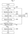
- Fig. 7 is a flowchart depicting the method for determining the optimum condition for the additive manufacturing according to the second embodiment.
- the method for determining the optimum condition for the additive manufacturing according to the second embodiment is a method for determining an optimum condition for additive manufacturing used when the additive manufacturing is performed using the metal powder.
- a setting condition of the additive manufacturing is set to the predetermined condition (a setting step S201).
- the additively manufactured test object including the reference part, the deformation part, and the coupling part arranged in the surface direction of the upper surface of the baseplate, in which the coupling part integrates the reference part and the deformation part, is manufactured on the upper surface of the baseplate such that the reference part, the deformation part, and the coupling part are joined to the upper surface of the baseplate (a manufacturing step S202).
- the target metal powder for which the optimum condition for additive manufacturing are determined for example, the powder of the stainless steel 316L
- the additively manufactured test object is separated from the upper surface of the baseplate (a separation step S203).
- the height h means of the deformation part based on the height h ref of the reference part (the deformation amount of the deformation part based on the reference part) of the additively manufactured test object separated from the upper surface of the baseplate is measured (a measurement step S204).
- the correction condition of the additive manufacturing is a condition of the additive manufacturing under which the height h means of the deformation part based on the height h ref of the reference part is inferred to be the predetermined value or less from the setting condition of the additive manufacturing and the height h means of the deformation part based on the height h ref of the reference part measured in the measurement step S204.
- the regression analysis constructs the known prediction models from the plurality of sets of teacher data in which the condition of the additive manufacturing used when the additive manufacturing is performed using the known metal powder is set as the explanatory variable and the height h means of the deformation part based on the height h ref of the reference part in this case is set as the objective variable.
- the prediction model that allows predicting the height h means of the deformation part based on the height h ref of the reference part measured at the measurement step S204 from the setting condition of the additive manufacturing is selected from the known prediction models.
- the setting condition of the additive manufacturing is determined as the optimum condition for additive manufacturing (a determination step S206). After the determination step S206, the method for determining the optimum condition for additive manufacturing according to the second embodiment is terminated.
- the setting step S201, the manufacturing step S202, the separation step S203, the measurement step 5204, and the adjustment step S205 are repeated in this order until the optimum condition for additive manufacturing are determined, and at the setting step S201 after the adjustment step S205, the correction condition of the additive manufacturing obtained in the adjustment step S205 is set as the predetermined condition.
- the setting condition of the additive manufacturing is set to the predetermined condition.
- An initial condition set as the predetermined condition in the first setting step is not specifically limited, and may be any of conditions of a list of the conditions of additive manufacturing designed to measure a limit of the metal powder used for the additive manufacturing. Additionally, the initial condition may be a known condition specified or approved as the optimum condition for additive manufacturing of the metal powder.
- the correction condition of the additive manufacturing obtained in the adjustment step is set as the predetermined condition.
- the manufacturing step, the separation step, and the measurement step are similar to the manufacturing step, the separation step, and the measurement step described in the item of "A. Method for Measuring Deformation Amount of Deformation Part of Additively Manufactured Test Object and Method for Determining Optimum condition for Additive manufacturing Using Same” except that the additive manufacturing is performed under the setting condition set in the setting step in the manufacturing step.
- the present invention is not limited to the above embodiments but has the configuration substantially same as the technical idea described in the claims of the present invention, the technical scope of the invention encompasses any construction that has the similar operation and effects, and various modifications are included.
- the embodiments have been described in detail in a clearly understandable way of the present invention, and are not necessarily limited to those having all the described configurations.
- some of the configurations of a certain embodiment can be replaced with the configurations of the other embodiments, and the configurations of the other embodiments can be added to the configurations of the certain embodiment.
- some of the configurations of each embodiment can be added to, omitted, and replaced with other configurations.
Landscapes
- Engineering & Computer Science (AREA)
- Chemical & Material Sciences (AREA)
- Materials Engineering (AREA)
- Manufacturing & Machinery (AREA)
- Automation & Control Theory (AREA)
- Physics & Mathematics (AREA)
- Plasma & Fusion (AREA)
- Powder Metallurgy (AREA)
- Sampling And Sample Adjustment (AREA)
Applications Claiming Priority (2)
| Application Number | Priority Date | Filing Date | Title |
|---|---|---|---|
| JP2021171182 | 2021-10-19 | ||
| PCT/JP2022/038762 WO2023068268A1 (ja) | 2021-10-19 | 2022-10-18 | 付加製造試験体の変形部の変形量の測定方法及び付加製造の適正条件の決定方法 |
Publications (1)
| Publication Number | Publication Date |
|---|---|
| EP4420812A1 true EP4420812A1 (en) | 2024-08-28 |
Family
ID=86059156
Family Applications (1)
| Application Number | Title | Priority Date | Filing Date |
|---|---|---|---|
| EP22883572.4A Withdrawn EP4420812A1 (en) | 2021-10-19 | 2022-10-18 | Method for measuring deformation amount of deformation part of additively fabricated test object and method for determining proper conditions for additive fabrication |
Country Status (4)
| Country | Link |
|---|---|
| US (1) | US20240335879A1 (https=) |
| EP (1) | EP4420812A1 (https=) |
| JP (1) | JPWO2023068268A1 (https=) |
| WO (1) | WO2023068268A1 (https=) |
Families Citing this family (1)
| Publication number | Priority date | Publication date | Assignee | Title |
|---|---|---|---|---|
| JP2025028001A (ja) * | 2023-08-17 | 2025-02-28 | 株式会社プロテリアル | 付加造形物の割れ評価方法、および割れ評価器 |
Family Cites Families (12)
| Publication number | Priority date | Publication date | Assignee | Title |
|---|---|---|---|---|
| ES2983485T3 (es) * | 2015-11-16 | 2024-10-23 | Renishaw Plc | Método y aparato de fabricación aditiva |
| US10549478B2 (en) * | 2016-02-11 | 2020-02-04 | General Electric Company | Methods and surrounding supports for additive manufacturing |
| US10471695B2 (en) * | 2016-10-26 | 2019-11-12 | General Electric Company | Methods and thermal structures for additive manufacturing |
| US10545806B2 (en) * | 2017-06-05 | 2020-01-28 | International Business Machines Corporation | Proximity correction in three-dimensional manufacturing |
| CN110570512B (zh) * | 2018-06-06 | 2024-02-02 | 哈米尔顿森德斯特兰德公司 | 包括利用形状变换的补偿建模方法的增材制造 |
| EP3587005A1 (en) * | 2018-06-26 | 2020-01-01 | Siemens Aktiengesellschaft | Control method for layerwise additive manufacturing, computer program product and control apparatus |
| US11079739B2 (en) | 2019-02-25 | 2021-08-03 | General Electric Company | Transfer learning/dictionary generation and usage for tailored part parameter generation from coupon builds |
| US11472115B2 (en) | 2019-03-21 | 2022-10-18 | General Electric Company | In-situ monitoring system assisted material and parameter development for additive manufacturing |
| JP7197437B2 (ja) * | 2019-07-19 | 2022-12-27 | 株式会社神戸製鋼所 | 積層造形物の積層計画方法、積層造形物の製造方法及び製造装置 |
| JP7531884B2 (ja) | 2020-04-21 | 2024-08-13 | 株式会社ユニバーサルエンターテインメント | 遊技機 |
| DE102021103739A1 (de) * | 2021-02-17 | 2022-08-18 | Te Connectivity Germany Gmbh | Additives Fertigungssystem mit einer Mehrzahl von Fertigungsstationen und Verfahren zur additiven Fertigung einer Mehrzahl von Werkstücken |
| EP4170537B1 (en) * | 2021-10-20 | 2025-04-23 | General Electric Company | Systems and methods to improve the accuracy and manufacturability in an additive manufacturing compensation process |
-
2022
- 2022-10-18 JP JP2023554705A patent/JPWO2023068268A1/ja active Pending
- 2022-10-18 EP EP22883572.4A patent/EP4420812A1/en not_active Withdrawn
- 2022-10-18 WO PCT/JP2022/038762 patent/WO2023068268A1/ja not_active Ceased
- 2022-10-18 US US18/690,318 patent/US20240335879A1/en active Pending
Also Published As
| Publication number | Publication date |
|---|---|
| JPWO2023068268A1 (https=) | 2023-04-27 |
| US20240335879A1 (en) | 2024-10-10 |
| WO2023068268A1 (ja) | 2023-04-27 |
Similar Documents
| Publication | Publication Date | Title |
|---|---|---|
| Zok et al. | A protocol for characterizing the structural performance of metallic sandwich panels: application to pyramidal truss cores | |
| Balawi et al. | The effect of honeycomb relative density on its effective in-plane elastic moduli: An experimental study | |
| Safronov et al. | Distortions and residual stresses at layer-by-layer additive manufacturing by fusion | |
| Rathbun et al. | Measurement and simulation of the performance of a lightweight metallic sandwich structure with a tetrahedral truss core | |
| EP4420812A1 (en) | Method for measuring deformation amount of deformation part of additively fabricated test object and method for determining proper conditions for additive fabrication | |
| EP3931650B1 (en) | Method and system for optimizing process parameters in an additive manufacturing process | |
| Yadav et al. | A nondestructive technique for the evaluation of thin cylindrical shells' axial buckling capacity | |
| EP3566040B1 (en) | Apparatus and method for rapid screening of material properties in a plurality of additively manufactured test specimens | |
| JP6640658B2 (ja) | クリープ損傷評価方法 | |
| Jalali et al. | Creep of Metallic Materials in Bending: Jalali, Kumar, and Jayaram | |
| Van Driel et al. | Response surface modeling for nonlinear packaging stresses | |
| Miller et al. | Three-dimensional effects of the bend–stretch forming of aluminum tubes | |
| CN118013787A (zh) | 考虑扫描时序的增材制造多尺度仿真与优化方法 | |
| Terrenoir et al. | Influence of wire feed speed and torch speed on the mechanical properties of wire arc additively manufactured stainless steel | |
| JPWO2005104258A1 (ja) | 弾性体の検査方法、検査装置、及び寸法予測プログラム | |
| Medina | Effect of membrane load on the stability of an electrostatically actuated initially curved circular micro plate | |
| Wu et al. | Parameter optimization and compressive property of the TC31 titanium alloy X-type lattice structure by the superplastic forming/diffusion bonding process | |
| JP4516740B2 (ja) | 形状推定装置 | |
| Kapusuzoglu et al. | Process optimization under uncertainty for improving the bond quality of polymer filaments in fused filament fabrication | |
| Lin et al. | Design and optimization of a long-stroke compliant micropositioning stage driven by voice coil motor | |
| Yang et al. | Density prediction for selective laser melting fabricated of CuCrZr alloy using hybrid Gaussian boosted regression | |
| Barrios et al. | Comparison of the low and high/very high cycle fatigue behaviors in Ni microbeams under bending | |
| Lingam et al. | Mechanics-based integrated product and process design for incremental forming | |
| Zhang et al. | Comparative study of various hardening models for the prediction of plastic responses under strain path change conditions | |
| Li et al. | A study of displacement distribution in a piezoelectric heterogeneous bimorph |
Legal Events
| Date | Code | Title | Description |
|---|---|---|---|
| STAA | Information on the status of an ep patent application or granted ep patent |
Free format text: STATUS: THE INTERNATIONAL PUBLICATION HAS BEEN MADE |
|
| PUAI | Public reference made under article 153(3) epc to a published international application that has entered the european phase |
Free format text: ORIGINAL CODE: 0009012 |
|
| STAA | Information on the status of an ep patent application or granted ep patent |
Free format text: STATUS: REQUEST FOR EXAMINATION WAS MADE |
|
| 17P | Request for examination filed |
Effective date: 20240308 |
|
| AK | Designated contracting states |
Kind code of ref document: A1 Designated state(s): AL AT BE BG CH CY CZ DE DK EE ES FI FR GB GR HR HU IE IS IT LI LT LU LV MC ME MK MT NL NO PL PT RO RS SE SI SK SM TR |
|
| DAV | Request for validation of the european patent (deleted) | ||
| DAX | Request for extension of the european patent (deleted) | ||
| STAA | Information on the status of an ep patent application or granted ep patent |
Free format text: STATUS: THE APPLICATION HAS BEEN WITHDRAWN |
|
| 18W | Application withdrawn |
Effective date: 20251008 |