WO2023068001A1 - 通信装置および電子機器 - Google Patents
通信装置および電子機器 Download PDFInfo
- Publication number
- WO2023068001A1 WO2023068001A1 PCT/JP2022/036229 JP2022036229W WO2023068001A1 WO 2023068001 A1 WO2023068001 A1 WO 2023068001A1 JP 2022036229 W JP2022036229 W JP 2022036229W WO 2023068001 A1 WO2023068001 A1 WO 2023068001A1
- Authority
- WO
- WIPO (PCT)
- Prior art keywords
- communication
- external connection
- terminal
- terminals
- communication terminal
- Prior art date
- Legal status (The legal status is an assumption and is not a legal conclusion. Google has not performed a legal analysis and makes no representation as to the accuracy of the status listed.)
- Ceased
Links
Images







Classifications
-
- H—ELECTRICITY
- H04—ELECTRIC COMMUNICATION TECHNIQUE
- H04B—TRANSMISSION
- H04B1/00—Details of transmission systems, not covered by a single one of groups H04B3/00 - H04B13/00; Details of transmission systems not characterised by the medium used for transmission
- H04B1/005—Details of transmission systems, not covered by a single one of groups H04B3/00 - H04B13/00; Details of transmission systems not characterised by the medium used for transmission adapting radio receivers, transmitters andtransceivers for operation on two or more bands, i.e. frequency ranges
- H04B1/0067—Details of transmission systems, not covered by a single one of groups H04B3/00 - H04B13/00; Details of transmission systems not characterised by the medium used for transmission adapting radio receivers, transmitters andtransceivers for operation on two or more bands, i.e. frequency ranges with one or more circuit blocks in common for different bands
-
- H—ELECTRICITY
- H03—ELECTRONIC CIRCUITRY
- H03K—PULSE TECHNIQUE
- H03K17/00—Electronic switching or gating, i.e. not by contact-making and –breaking
-
- H—ELECTRICITY
- H04—ELECTRIC COMMUNICATION TECHNIQUE
- H04B—TRANSMISSION
- H04B1/00—Details of transmission systems, not covered by a single one of groups H04B3/00 - H04B13/00; Details of transmission systems not characterised by the medium used for transmission
- H04B1/005—Details of transmission systems, not covered by a single one of groups H04B3/00 - H04B13/00; Details of transmission systems not characterised by the medium used for transmission adapting radio receivers, transmitters andtransceivers for operation on two or more bands, i.e. frequency ranges
- H04B1/0053—Details of transmission systems, not covered by a single one of groups H04B3/00 - H04B13/00; Details of transmission systems not characterised by the medium used for transmission adapting radio receivers, transmitters andtransceivers for operation on two or more bands, i.e. frequency ranges with common antenna for more than one band
- H04B1/006—Details of transmission systems, not covered by a single one of groups H04B3/00 - H04B13/00; Details of transmission systems not characterised by the medium used for transmission adapting radio receivers, transmitters andtransceivers for operation on two or more bands, i.e. frequency ranges with common antenna for more than one band using switches for selecting the desired band
-
- H—ELECTRICITY
- H04—ELECTRIC COMMUNICATION TECHNIQUE
- H04B—TRANSMISSION
- H04B1/00—Details of transmission systems, not covered by a single one of groups H04B3/00 - H04B13/00; Details of transmission systems not characterised by the medium used for transmission
- H04B1/005—Details of transmission systems, not covered by a single one of groups H04B3/00 - H04B13/00; Details of transmission systems not characterised by the medium used for transmission adapting radio receivers, transmitters andtransceivers for operation on two or more bands, i.e. frequency ranges
- H04B1/0064—Details of transmission systems, not covered by a single one of groups H04B3/00 - H04B13/00; Details of transmission systems not characterised by the medium used for transmission adapting radio receivers, transmitters andtransceivers for operation on two or more bands, i.e. frequency ranges with separate antennas for the more than one band
-
- H—ELECTRICITY
- H04—ELECTRIC COMMUNICATION TECHNIQUE
- H04B—TRANSMISSION
- H04B1/00—Details of transmission systems, not covered by a single one of groups H04B3/00 - H04B13/00; Details of transmission systems not characterised by the medium used for transmission
- H04B1/38—Transceivers, i.e. devices in which transmitter and receiver form a structural unit and in which at least one part is used for functions of transmitting and receiving
-
- Y—GENERAL TAGGING OF NEW TECHNOLOGICAL DEVELOPMENTS; GENERAL TAGGING OF CROSS-SECTIONAL TECHNOLOGIES SPANNING OVER SEVERAL SECTIONS OF THE IPC; TECHNICAL SUBJECTS COVERED BY FORMER USPC CROSS-REFERENCE ART COLLECTIONS [XRACs] AND DIGESTS
- Y02—TECHNOLOGIES OR APPLICATIONS FOR MITIGATION OR ADAPTATION AGAINST CLIMATE CHANGE
- Y02D—CLIMATE CHANGE MITIGATION TECHNOLOGIES IN INFORMATION AND COMMUNICATION TECHNOLOGIES [ICT], I.E. INFORMATION AND COMMUNICATION TECHNOLOGIES AIMING AT THE REDUCTION OF THEIR OWN ENERGY USE
- Y02D30/00—Reducing energy consumption in communication networks
- Y02D30/70—Reducing energy consumption in communication networks in wireless communication networks
Definitions
- the present disclosure relates to communication devices and electronic devices.
- Patent Document 1 discloses a technique for supporting multiple radios on a radio device with a limited number of antennas.
- at least one antenna may be selected for at least one radio from among multiple antennas, eg, based on a configurable mapping of the multiple antennas to the multiple radios.
- One or more antennas may be shared between radios to reduce the number of antennas.
- At least one radio may be connected to at least one antenna, for example, through a switch filter. Antenna selection may be performed dynamically.
- An object of the present disclosure is to provide a communication device and an electronic device that improve the degree of freedom of external connection terminals.
- a communication device includes: a communication module having a plurality of communication terminals; a plurality of internal antennas configured to be connectable to the plurality of communication terminals; a plurality of external connection terminals configured to be connectable with the plurality of communication terminals; a first switch device disposed between the plurality of communication terminals and the plurality of internal antennas, and switching connection destinations of the plurality of communication terminals to the plurality of internal antennas or the plurality of external connection terminals; One or a plurality of communication terminals among a plurality of communication terminals arranged between the first switch device and the plurality of external connection terminals and connected to the first switch device are connected to the plurality of external connection terminals. a second switch device connected to one or more external connection terminals of a control unit that controls the first switch device and the second switch device; Prepare.
- An electrical appliance of one aspect of the present disclosure includes the communication device of the aspect described above.
- FIG. 1 is a schematic block diagram showing an example of a configuration of a communication device according to Embodiment 1 of the present disclosure
- FIG. 1 is a schematic diagram showing an example of a circuit configuration of a communication device according to Embodiment 1 of the present disclosure
- FIG. It is a table
- 4 is a table showing an example of connection settings of a plurality of communication terminals, a plurality of internal antennas, and a plurality of external connection terminals
- 1 is a schematic diagram showing an example of a specific configuration of a communication device according to Embodiment 1 of the present disclosure
- FIG. 1 is a schematic block diagram showing an example of a configuration of a communication device according to Embodiment 1 of the present disclosure
- FIG. 1 is a schematic diagram showing an example of a circuit configuration of a communication device according to Embodiment 1 of the present disclosure
- FIG. It is a table
- FIG. 4 is a table showing an example of control signals for controlling the first switch device and the second switch device; 1 is a schematic diagram showing Example 1 of a communication device; FIG. 4 is a table showing an example of control signals in Example 1.
- FIG. FIG. 3 is a schematic diagram showing a second embodiment of a communication device; 10 is a table showing an example of control signals in Example 2.
- FIG. 11 is a schematic diagram showing a communication device according to a third embodiment; 11 is a table showing an example of control signals in Example 3; 7 is a table showing an example of a control signal when using an Invert signal; FIG.
- FIG. 4 is a schematic block diagram showing an example of a configuration of an electronic device according to Embodiment 2 of the present disclosure; 4 is a schematic diagram illustrating an example of connection settings of a plurality of external connection terminals; FIG. 4 is a schematic diagram illustrating an example of connection settings of a plurality of external connection terminals; FIG.
- a communication device that transmits and receives wireless signals by switching between an internal antenna and an external antenna.
- a communication device is installed in an electronic device such as a laptop PC, a tablet PC, or a smartphone, for example.
- An internal antenna is an antenna housed in an electronic device.
- An external antenna is an antenna arranged outside the electronic device and connected to an external connection terminal of the communication device.
- a communication device has a plurality of communication terminals, and switches connection destinations of the plurality of communication terminals to a plurality of internal antennas and a plurality of external connection terminals.
- the plurality of external connection terminals are connected to the plurality of communication terminals in a one-to-one relationship. That is, one predetermined communication terminal is connected to one external connection terminal. Therefore, there is a problem that the degree of freedom of the external connection terminals is low.
- the number of communication terminals, internal antennas, and external antennas tends to increase in order to support the 5th generation mobile communication system (5G: 5th Generation Mobile Communication System).
- 5G 5th Generation Mobile Communication System
- the number of wires connecting the communication terminals, internal antennas, and external connection terminals increases. Further, when mounting a plurality of communication modules with different communication methods in an electronic device, a substrate is prepared for each communication method.
- the present inventors proposed a first switch device for switching connection destinations of a plurality of communication terminals of a wireless communication module to a plurality of internal antennas or a plurality of external connection terminals, and a plurality of communication terminals connected to the first switch device. and a second switch device that selects one or more communication terminals from among and connects them to one or more external connection terminals, resulting in the following invention.
- a communication device includes a communication module having a plurality of communication terminals, a plurality of internal antennas arranged to be connectable to the plurality of communication terminals, and a plurality of internal antennas arranged to be connectable to the plurality of communication terminals. and a plurality of external connection terminals disposed between the plurality of communication terminals and the plurality of internal antennas, wherein connection destinations of the plurality of communication terminals are switched to the plurality of internal antennas or the plurality of external connection terminals.
- 1 switch device, and one or more communication terminals are selected from among a plurality of communication terminals arranged between the first switch device and the plurality of external connection terminals and connected to the first switch device.
- a second switch device connected to one or a plurality of external connection terminals among the plurality of external connection terminals; and a control unit for controlling the first switch device and the second switch device.
- the first switch device has a plurality of first switches arranged between the plurality of communication terminals and the plurality of internal antennas
- the second switch device has a plurality of second switches arranged between the plurality of first switches and the plurality of external connection terminals, each of the plurality of second switches being two of the plurality of first switches. It may be connected in series with one or more first switches.
- the communication modules include a first communication module that supports WWAN (Wireless Wide Area Network) communication, a second communication module that receives a GNSS (Global Navigation Satellite System) signal, and a third communication module that supports WLAN (Wireless Local Area Network) communication.
- WWAN Wireless Wide Area Network
- GNSS Global Navigation Satellite System
- WLAN Wireless Local Area Network
- the communication module may include the first communication module, and the number of the plurality of external connection terminals may be 4 or more and 7 or less.
- the plurality of external connection terminals have a first external connection terminal, a second external connection terminal, a third external connection terminal, and a fourth external connection terminal
- the module has a first communication terminal, a second communication terminal, a third communication terminal and a fourth communication terminal for transmitting and receiving WWAN signals
- the second communication module has a fifth communication terminal for GNSS signals.
- the third communication module has a sixth communication terminal and a seventh communication terminal for transmitting and receiving WLAN signals
- the first external connection terminal is connected to the first communication terminal
- the second switch device comprises: a first external connection selection switch that selects either the second communication terminal or the fifth communication terminal and connects the selected second communication terminal or the fifth communication terminal to the second external connection terminal; a second external connection selection switch that selects either the second communication terminal or the third communication terminal and connects the selected second communication terminal or the third communication terminal to the third external connection terminal; a third external connection selection switch that selects either the fourth communication terminal or the sixth communication terminal and connects the selected fourth communication terminal or the sixth communication terminal to the fourth external connection terminal; may have
- the second communication terminal corresponds to a WWAN signal and a WWAN-GPS signal
- the first external connection selection switch is configured to connect the second communication terminal and the second external
- the control unit causes the second external connection selection switch to not connect the second communication terminal and the third external connection terminal, and the second external connection selection switch is set to the second communication terminal.
- the control unit may not connect the second communication terminal and the second external connection terminal in the first external connection selection switch.
- control unit may control the first switching device and the second switching device using an Invert signal.
- An electronic device includes the communication device according to the aspect.
- the electronic device further comprising a storage unit that stores connection setting information between the plurality of communication terminals and the plurality of external connection terminals, wherein the connection settings are made by a BIOS (Basic Input Output System)
- BIOS Basic Input Output System
- the information may be set and stored in the storage unit, and the control unit may control the first switch device and the second switch device based on the connection setting information stored in the storage unit.
- control unit can control the first switch device and the second switch device based on the connection settings set in the BIOS.
- first and second are used for descriptive purposes only and are understood to indicate or imply relative importance or order of technical features. shouldn't.
- a feature that is qualified as “first” and “second” expressly or implicitly includes one or more of such features.
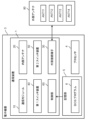
- FIG. 1 is a schematic block diagram showing an example of the configuration of a communication device 1 according to Embodiment 1 of the present disclosure.
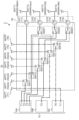
- FIG. 2 is a schematic diagram showing an example of a circuit configuration of the communication device 1 of Embodiment 1 according to the present disclosure.
- the communication device 1 includes a communication module 10, multiple internal antennas 20, multiple external connection terminals 30, a first switch device 40, a second switch device 50, and a control unit 60.
- the communication device 1 is a device that wirelessly communicates with an external device by transmitting and/or receiving wireless signals in accordance with a wireless communication scheme supported by the communication module 10 .
- the communication module 10 is a device that transmits and/or receives radio signals. As shown in FIG. 2, the communication module 10 has a plurality of communication terminals T1-T7. A plurality of communication terminals T1 to T7 are terminals for transmitting and/or receiving radio signals. The plurality of communication terminals T1 to T7 are connected to the plurality of internal antennas 20 or the plurality of external connection terminals 30 to receive radio signals from external devices or transmit radio signals to external devices.
- the communication module 10 has three communication modules 10A to 10C with different frequency bands. That is, the communication module 10 has a first communication module 10A, a second communication module 10B and a third communication module 10C. The communication module 10 also has seven communication terminals T1 to T7.
- the seven communication terminals T1 to T7 are defined as a first communication terminal T1, a second communication terminal T2, a third communication terminal T3, a fourth communication terminal T4, a fifth communication terminal T5, a sixth communication terminal T6 and It may be called a seventh communication terminal T7.
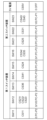
- FIG. 3 is a table showing an example of the communication method of the communication module 10 and communication terminals T1 to T7.
- the first communication module 10A supports WWAN (Wireless Wide Area Network) communication.
- the first communication module 10A supports radio signals of 600 MHz or more and 6 GHz or less.
- the first communication module 10A has four communication terminals T1 to T4 corresponding to the WWAN signal wireless communication system.
- the first communication module 10A has a first communication terminal T1, a second communication terminal T2, a third communication terminal T3, and a fourth communication terminal T4 for transmitting and receiving WWAN signals.
- the first communication terminal T1, the second communication terminal T2, the third communication terminal T3 and the fourth communication terminal T4 are respectively the WWAN-main terminal T1, the WWAN-aux terminal T2, the WWAN-3rd terminal T3 and the WWAN-4th terminal T4. is.
- the second communication terminal T2 can use both WWAN signals and WWAN-GPS signals.
- the second communication terminal T2 can be used by switching between the WWAN signal and the WWAN-GPS signal.
- the "WWAN signal” is a radio signal in the frequency band used for WWAN communication, for example, 600 MHz or more and 6 GHz or less.
- a "WWAN-GPS signal” is a GPS (Global Positioning System) signal in a frequency band that can be used in WWAN communication, for example, a 1.5 GHz band.
- the second communication module 10B supports GNSS (Global Navigation Satellite System) signals.
- GNSS Global Navigation Satellite System
- the second communication module 10B receives a 1575.42 MHz GPS signal, a 1602 MHz GLONASS signal, a 1561.098 MHz BeiDou signal, and the like.
- the second communication module 10B has one communication terminal T5 corresponding to the wireless communication method of GNSS signals.
- the first communication module 10A has a fifth communication terminal T5 for receiving GNSS signals.
- the fifth communication terminal T5 is the RF terminal T5.
- the third communication module 10C supports WLAN (Wireless Local Area Network) communication.
- the third communication module 10C supports radio signals in the 2.4 GHz band or 5 GHz band.
- the third communication module 10C has two communication terminals T6 and T7 corresponding to the wireless communication method of WLAN signals.
- the third communication module 10C has a sixth communication terminal T6 and a seventh communication terminal T7 for transmitting and receiving WLAN signals.
- the sixth communication terminal T6 and the seventh communication terminal T7 are the WLAN-main terminal T6 and the WLAN-aux terminal T7.
- the WLAN-aux terminal T7 is compatible with Bluetooth signals.
- a plurality of internal antennas 20 are arranged so as to be connectable to a plurality of communication terminals T1 to T7.
- a plurality of internal antennas 20 are arranged inside an electronic device in which the communication device 1 is housed.
- a plurality of internal antennas 20 radiate wireless signals toward and/or receive wireless signals from external devices.
- the plurality of internal antennas 20 are connected to the plurality of communication terminals T1 to T7 via wiring.
- the multiple internal antennas 20 have seven internal antennas ANT1 to ANT7.
- Seven internal antennas ANT1 to ANT7 are arranged so as to be connectable to seven communication terminals T1 to T7 via wires.
- the plurality of internal antennas 20 are connected to the plurality of communication terminals T1 to T7 via the first switch device 40. Connections between the plurality of internal antennas 20 and the plurality of communication terminals T1 to T7 are controlled by switching the first switch device 40. FIG.
- six internal antennas ANT1 to ANT6 are connected to six communication terminals T1 to T6 via the first switch device 40, and one internal antenna ANT7 is the first antenna. It is directly connected to one communication terminal T7 via wiring without going through the switch device 40 .
- the seven internal antennas ANT1-ANT7 are herein referred to as first internal antenna ANT1, second internal antenna ANT2, third internal antenna ANT3, fourth internal antenna ANT4, fifth internal antenna ANT5, sixth internal antenna ANT6 and It may be called a seventh internal antenna ANT7.
- the plurality of external connection terminals 30 are arranged so as to be connectable with the plurality of communication terminals T1 to T7.
- a plurality of external connection terminals 30 are terminals connected to a plurality of external antennas ANT11 to ANT14.
- the multiple external antennas ANT11 to ANT14 include, for example, 5G/LTE external antennas, GPS external antennas, Wi-Fi external antennas, and the like.
- the plurality of external connection terminals 30 are connected to the plurality of external antennas ANT11 to ANT14 to radiate radio signals toward external devices and/or receive radio signals from external devices.
- the plurality of external connection terminals 30 are connected to the plurality of communication terminals T1 to T7 via wiring.
- the plurality of external connection terminals 30 has four external connection terminals CH1 to CH4.
- the four external connection terminals CH1 to CH4 are arranged so as to be connectable to the six communication terminals T1 to T6 via wires.
- the plurality of external connection terminals 30 are connected to the plurality of communication terminals T1 to T6 via the first switch device 40 and the second switch device 50. Connections between the plurality of external connection terminals 30 and the plurality of communication terminals T1 to T6 are controlled by switching the first switch device 40 and the second switch device 50.
- one external connection terminal CH1 is connected to one communication terminal T1 via the first switch device 40, and three external connection terminals CH2 to CH4 are connected to the first It is connected to five communication terminals T2-T6 via the switch device 40 and the second switch device 50.
- the four external connection terminals CH1 to CH4 may be referred to as a first external connection terminal CH1, a second external connection terminal CH2, a third external connection terminal CH3 and a fourth external connection terminal CH4.
- the first switch device 40 is arranged between the plurality of communication terminals T1 to T6 and the plurality of internal antennas 20, and connects the plurality of communication terminals T1 to T6 to the plurality of internal antennas 20 or the plurality of external connection terminals 30. switch to That is, the first switch device 40 has a first connection that connects the plurality of communication terminals T1 to T6 and the plurality of internal antennas 20, and a second connection that connects the plurality of communication terminals T1 to T6 to the plurality of external connection terminals 30. Switch between 2 connection and .
- the first switch device 40 has a plurality of first switches SW11 to SW16.
- the plurality of first switches SW11-SW16 are arranged between the plurality of communication terminals T1-T6 and the plurality of internal antennas ANT1-ANT6, respectively.
- six first switches SW11 to SW16 are arranged between six communication terminals T1 to T6 and six internal antennas ANT1 to ANT6.
- the six first switches SW11 to SW16 are defined as a first internal connection selection switch SW11, a second internal connection selection switch SW12, a third internal connection selection switch SW13, a fourth internal connection selection switch SW14, and a fifth internal connection selection switch SW14. They may be referred to as a connection selection switch SW15 and a sixth internal connection selection switch SW16.
- the first internal connection selection switch SW11 is arranged between the first communication terminal T1 and the first internal antenna ANT1, and switches the connection destination of the first communication terminal T1 to the first internal antenna ANT1 or the first external connection terminal CH1. . Specifically, the first internal connection selection switch SW11 is connected to the first internal antenna ANT1 and the first external connection terminal CH1 via two wires. The first internal connection selection switch SW11 selects either the wiring connected to the first internal antenna ANT1 or the wiring connected to the first external connection terminal CH1.
- the second internal connection selection switch SW12 is arranged between the second communication terminal T2 and the second internal antenna ANT2. 3 Switch to the external connection terminal CH3. Specifically, the second internal connection selection switch SW12 is connected to the second internal antenna ANT2, the second external connection terminal CH2 and the third external connection terminal CH3 via three wires. The second internal connection selection switch SW12 selects one of the wiring connected to the first internal antenna ANT1, the wiring connected to the second external connection terminal CH2, and the wiring connected to the third external connection terminal CH3. Choose one.
- a second switch device 50 is arranged between the wiring connected to the second external connection terminal CH2 and the wiring connected to the third external connection terminal CH3. The connection destination of the terminal T2 is controlled.
- the third internal connection selection switch SW13 is arranged between the third communication terminal T3 and the third internal antenna ANT3, and switches the connection destination of the third communication terminal T3 to the third internal antenna ANT3 or the third external connection terminal CH3. .
- the third internal connection selection switch SW13 is connected to the third internal antenna ANT3 and the third external connection terminal CH3 via two wirings.
- the third internal connection selection switch SW13 selects either the wiring connected to the third internal antenna ANT3 or the wiring connected to the third external connection terminal CH3.
- a second switch device 50 is arranged in the wiring connected to the third external connection terminal CH3, and the second switch device 50 controls the connection destination of the third communication terminal T3.
- the fourth internal connection selection switch SW14 is arranged between the fourth communication terminal T4 and the fourth internal antenna ANT4, and switches the connection destination of the fourth communication terminal T4 to the fourth internal antenna ANT4 or the fourth external connection terminal CH4. .
- the fourth internal connection selection switch SW14 is connected to the fourth internal antenna ANT4 and the fourth external connection terminal CH4 via two wires.
- the fourth internal connection selection switch SW14 selects either the wiring connected to the fourth internal antenna ANT4 or the wiring connected to the fourth external connection terminal CH4.
- a second switch device 50 is arranged in the wiring connected to the fourth external connection terminal CH4, and the second switch device 50 controls the connection destination of the fourth communication terminal T4.
- the fifth internal connection selection switch SW15 is arranged between the fifth communication terminal T5 and the fifth internal antenna ANT5, and switches the connection destination of the fifth communication terminal T5 to the fifth internal antenna ANT5 or the second external connection terminal CH2. . Specifically, the fifth internal connection selection switch SW15 is connected to the fifth internal antenna ANT5 and the second external connection terminal CH2 via two wires. The fifth internal connection selection switch SW15 selects either the wiring connected to the fifth internal antenna ANT5 or the wiring connected to the second external connection terminal CH2.
- a second switch device 50 is arranged on the wiring connected to the second external connection terminal CH2, and the second switch device 50 controls the connection destination of the fifth communication terminal T5.
- the sixth internal connection selection switch SW16 is arranged between the sixth communication terminal T6 and the sixth internal antenna ANT6, and switches the connection destination of the sixth communication terminal T6 to the sixth internal antenna ANT6 or the fourth external connection terminal CH4. . Specifically, the sixth internal connection selection switch SW16 is connected to the sixth internal antenna ANT6 and the fourth external connection terminal CH4 via two wirings. The sixth internal connection selection switch SW16 selects either the wiring connected to the sixth internal antenna ANT6 or the wiring connected to the fourth external connection terminal CH4. A second switch device 50 is arranged in the wiring connected to the fourth external connection terminal CH4, and the second switch device 50 controls the connection destination of the sixth communication terminal T6.
- the plurality of first switches SW11 to SW16 constituting the first switch device 40 are, for example, SPDT (Single-Pole Double-Throw) switches and SP3T (Single-Pole 3-Throw) switches dedicated to RF (Radio Frequency) of GaAsMMIC.
- SPDT Single-Pole Double-Throw
- SP3T Single-Pole 3-Throw switches dedicated to RF (Radio Frequency) of GaAsMMIC.
- the plurality of first switches SW11 to SW16 are not limited to this, and may be relays and/or semiconductor switches such as MOSFETs and IGBTs.
- the second switch device 50 is arranged between the first switch device 40 and the plurality of external connection terminals 30, and selects one or more of the plurality of communication terminals T2 to T6 connected to the first switch device 40.
- the communication terminals T2 to T4 are selected and connected to one or a plurality of external connection terminals CH2 to CH4 out of the plurality of external connection terminals 30 .
- the second switch device 50 is connected to the first switch device 40 and the plurality of external connection terminals 30 via wires.
- the second switch device 50 selects connection destinations of the plurality of external connection terminals CH2 to CH4 from among the plurality of first switches SW11 to SW16.
- the second switch device 50 has a plurality of second switches SW21 to SW23.
- the plurality of second switches SW21-SW23 are arranged between the first switch device 40 and the plurality of external connection terminals CH2-CH4.
- three second switches SW21 to SW23 are arranged between five first switches SW12 to SW16 and three external connection terminals CH2 to CH4.
- Each of the plurality of second switches SW21 to SW23 is connected in series with two or more first switches among the plurality of first switches SW11 to SW16.
- the three second switches SW21 to SW23 may be referred to as a first external connection selection switch SW21, a second external connection selection switch SW22 and a third external connection selection switch SW23.
- the first external connection selection switch SW21 is connected in series with the second internal connection selection switch SW12 and the fifth internal connection selection switch SW15.
- the first external connection selection switch SW21 selects either the second communication terminal T2 connected to the second internal connection selection switch SW12 or the fifth communication terminal T5 connected to the fifth internal connection selection switch SW15.
- the first external connection selection switch SW21 connects the selected second communication terminal T2 or fifth communication terminal T5 to the second external connection terminal CH2.
- the first external connection selection switch SW21 is connected in series to the second internal connection selection switch SW12 and the fifth internal connection selection switch SW15 via two wirings.
- the first external connection selection switch SW21 selects either the wiring connected to the second internal connection selection switch SW12 or the wiring connected to the fifth internal connection selection switch SW15.
- the second external connection selection switch SW22 is connected in series with the second internal connection selection switch SW12 and the third internal connection selection switch SW13.
- the second external connection selection switch SW22 selects either the second communication terminal T2 connected to the second internal connection selection switch SW12 or the third communication terminal T3 connected to the third internal connection selection switch SW13.
- the second external connection selection switch SW22 connects the selected second communication terminal T2 or third communication terminal T3 to the third external connection terminal CH3.
- the second external connection selection switch SW22 is connected in series to the second internal connection selection switch SW12 and the third internal connection selection switch SW13 via two wirings.
- the second external connection selection switch SW22 selects either the wiring connected to the second internal connection selection switch SW12 or the wiring connected to the third internal connection selection switch SW13.
- the third external connection selection switch SW23 is connected in series with the fourth internal connection selection switch SW14 and the sixth internal connection selection switch SW16.
- the third external connection selection switch SW23 selects either the fourth communication terminal T4 connected to the fourth internal connection selection switch SW14 or the sixth communication terminal T6 connected to the sixth internal connection selection switch SW16.
- the third external connection selection switch SW23 connects the selected fourth communication terminal T4 or sixth communication terminal T6 to the third external connection terminal CH3.
- the third external connection selection switch SW23 is connected in series to the fourth internal connection selection switch SW14 and the sixth internal connection selection switch SW16 via two wirings.
- the third external connection selection switch SW23 selects either the wiring connected to the fourth internal connection selection switch SW14 or the wiring connected to the sixth internal connection selection switch SW16.
- the plurality of second switches SW21 to SW23 constituting the second switch device 50 are, for example, SPDT (Single-Pole Double-Throw) switches and SP3T (Single-Pole 3-Throw) switches dedicated to RF (Radio Frequency) of GaAsMMIC.
- the plurality of first switches SW11 to SW16 are not limited to this, and may be relays and/or semiconductor switches such as MOSFETs and IGBTs.
- FIG. 4 is a table showing an example of connection settings of a plurality of communication terminals T1 to T7, a plurality of internal antennas 20 and a plurality of external connection terminals 30.
- the first internal antenna ANT1 is set to either the first communication terminal T1 or "None”.
- the second internal antenna ANT2 is set to either the second communication terminal T2 or "None”.
- the third internal antenna ANT3 is set to either the third communication terminal T3 or "None”.
- the fourth internal antenna ANT4 is set to either the fourth communication terminal T4 or "None".
- the fifth internal antenna ANT5 is set to either the fifth communication terminal T5 or "None”.
- the sixth internal antenna ANT6 is set to either the sixth communication terminal T6 or "None”.
- a seventh internal antenna ANT7 is set to the seventh communication terminal T7.
- the first external connection terminal CH1 is set to either the first communication terminal T1 or "None”.
- the second external connection terminal CH2 is set to either the second communication terminal T2, the fifth communication terminal T5 or "None”.
- the third external connection terminal CH3 is set to either the second communication terminal T2, the third communication terminal T3, or "None.”
- the fourth external connection terminal CH4 is set to either the fourth communication terminal T4, the sixth communication terminal T6 or "None".
- None means that the communication terminal is not connected.
- the first communication terminal T1 is connected to the first internal antenna ANT1
- the first external connection terminal CH1 is "None" which is not connected to the first communication terminal T1.
- the control unit 60 controls the first switch device 40 and the second switch device 50 . Specifically, the control unit 60 controls switching of the plurality of first switches SW11 to SW16 and switching of the plurality of second switches SW21 to SW23. For example, the control unit 60 reads connection setting information stored in the storage unit of the electronic device, and switches the plurality of first switches SW11 to SW16 and the plurality of second switches SW21 to SW21 to SW16 based on the connection setting information. It controls switching of SW23.
- connection settings may be preset connection settings or may be connection settings set by the user.
- connection setting may be a setting for detecting the communication method of the external antenna connected to the plurality of external connection terminals 30 and automatically connecting the communication terminal corresponding to the detected communication method.
- the control unit 60 can be realized by a semiconductor element or the like.
- the control unit 60 includes a microcomputer, CPU (Central Processing Unit), MPU (Micro Processing Unit), GPU (Graphics Processing Unit), DSP (Digital Signal Processor), FPGA (Field Programmable Gate Array), or ASIC ( Specific Integrated Circuit).
- the functions of the control unit 60 may be configured only by hardware, or may be realized by combining hardware and software.
- the control unit 60 reads the data and programs stored in the storage unit and performs various arithmetic processing, thereby realizing predetermined functions.
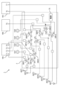
- FIG. 5 is a schematic diagram showing an example of a specific configuration of the communication device 1 according to Embodiment 1 of the present disclosure.
- the plurality of first switches SW11 to SW16 and the plurality of second switches SW21 to SW23 are switched to the first path PC-P1, the second path PC-P2 or the third path PC-P3.
- the first, third to sixth internal connection selection switches SW11, SW13 to SW16 and the first to third external connection selection switches SW21 to SW23 are switched to the first path PC-P1 or the second path PC-P2.
- the second internal connection selection switch SW12 switches to the first path PC-P1, the second path PC-P2 or the third path PC-P3.
- the plurality of first switches SW11 to SW16 and the plurality of second switches SW21 to SW23 change the connection destinations of the plurality of communication terminals T1 to T6 by switching the plurality of paths.
- the first switch SW11 connects the first communication terminal T1 and the first internal antenna ANT1 when switching to the first path PC-P1, and connects the first communication terminal T1 and the first internal antenna ANT1 when switching to the second path PC-P2. and the first external connection terminal CH1.
- the second internal connection selection switch SW12 connects the second communication terminal T2 and the second external selection switch SW22 when switching to the first path PC-P1.
- the second internal connection selection switch SW12 connects the second communication terminal T2 and the first external selection switch SW21 when switching to the second path PC-P2.
- the second internal connection selection switch SW12 connects the second communication terminal T2 and the second internal antenna ANT2 when switching to the third path PC-P3.
- the communication device 1 has a power supply 70.
- the power supply 70 is connected to wiring between the second external connection selection switch SW22 and the second external connection terminal CH2.
- the power supply 70 applies a voltage of, for example, 5V to the second external connection terminal CH2.
- the voltage applied to the second external connection terminal CH2 is used as a drive voltage for an external device connected to the second external connection terminal CH2, such as an external GPS.
- the power supply 70 applies a voltage to the second external connection terminal CH2. do.
- the fifth communication terminal T5 that receives the GNSS signal is connected to the second external connection terminal CH2, the power supply 70 applies voltage to the second external connection terminal CH2.
- the first switch device 40, the second switch device 50, and the wiring that constitute the communication device 1 are provided on one substrate 2.
- the control unit 60 sets switching of the first path PC-P1, the second path PC-P2, or the third path PC-P3 in the plurality of first switches SW11 to SW16 and the plurality of second switches SW21 to SW23 to "0" or It is controlled by a "1" control signal.
- FIG. 6 is a table showing an example of control signals for controlling the first switch device 40 and the second switch device 50.
- the control unit 60 uses 14 control signals CS11, CS21 to CS24, CS31, CS36, CS41 to 43, CS5V to control the plurality of first switches SW11 to SW16 and the plurality of second switches SW11 to SW16.
- SW21 to SW23 and the power supply 70 are controlled.
- the control unit 60 controls the first internal connection selection switch SW11 using the control signal CS11.
- the control unit 60 controls switching of the first internal connection selection switch SW11 by inputting the control signal CS11 of "0" or "1". Specifically, when the control unit 60 inputs the control signal CS11 of "0", the first internal connection selection switch SW11 is switched to the first path PC-P1. When the control unit 60 inputs the control signal CS11 of "1", it switches the first internal connection selection switch SW11 to the second path PC-P2.
- the control unit 60 controls the second internal connection selection switch SW12 using control signals CS21, CS22, and CS23.
- the control unit 60 controls switching of the second internal connection selection switch SW12 by inputting the control signals CS21, CS22 and CS23 of "0" or "1". Specifically, when the control unit 60 inputs the control signals CS21, CS22, CS23 of "1/0/0", the second internal connection selection switch SW12 is switched to the first path PC-P1. When the control unit 60 inputs the control signals CS21, CS22, CS23 of "0/1/0", it switches the second internal connection selection switch SW12 to the second path PC-P2. When the control unit 60 inputs the control signals CS21, CS22, CS23 of "0/0/1", it switches the second internal connection selection switch SW12 to the third path PC-P3.
- the control unit 60 controls the power supply 70 using the control signal CS5V.
- the control unit 60 controls the voltage application of the power supply 70 by inputting the control signal CS5V of "0" or "1". Specifically, when the control unit 60 inputs the control signal CS5V of "0", the power supply 70 is turned off and no voltage is applied. When the control unit 60 inputs the control signal CS5V of "1", the power supply 70 is turned on to apply a voltage.
- FIG. 7 is a schematic diagram showing Example 1 of the communication device 1.
- FIG. 8 is a table showing an example of control signals in the first embodiment shown in FIG. 7.
- FIG. 7 the solid line indicates connection to the external connection terminal 30
- the dashed-dotted line indicates connection to the internal antenna 20 .
- the first external connection terminal CH1 is connected to the first communication terminal T1
- the second external connection terminal CH2 is connected to the second communication terminal T2
- the third external connection terminal CH3 is connected.
- the fourth external connection terminal CH4 is connected to the fourth communication terminal T4.
- the first to fourth internal antennas ANT1 to ANT4 are "None".
- the fifth internal antenna ANT5 is connected to the fifth communication terminal T5, the sixth internal antenna ANT6 is connected to the sixth communication terminal T6, and the seventh internal antenna ANT7 is connected to the seventh communication terminal T7.
- the first communication terminal T1 is the WWAN-main terminal
- the second communication terminal T2 is the WWAN-aux terminal
- the third communication terminal T3 is the WWAN-3rd terminal
- the fourth communication terminal T4 is the WWAN-4rd terminal. terminal.
- the fifth communication terminal T5 is an RF terminal
- the sixth communication terminal T6 is a WLAN-main terminal
- the seventh communication terminal T7 is a WLAN-aux terminal (see FIG. 3).
- the second communication terminal T2 receives a WWAN-GPS signal.
- an external antenna for transmitting and receiving WWAN signals can be connected to the first external connection terminal CH1, the third external connection terminal CH3, and the fourth external connection terminal CH4.
- An external GPS that receives WWAN-GPS signals can be connected to the second external connection terminal CH2.
- control unit 60 uses the control signals shown in FIG. 8 to operate the plurality of first switches SW11 to SW16 and the plurality of second 2 switches SW21 to SW23 and the power supply 70 are controlled.
- the second communication terminal T2 is used in the WWAN-GPS signal communication system and is connected to the second external connection terminal CH2.
- the control unit 60 does not connect the second communication terminal T2 and the third external connection terminal CH3 in the second external connection selection switch SW22.
- the control unit 60 causes the second external connection selection switch SW22 to switch between the second communication terminal T2 and the third external connection terminal CH3. Exclusive processing is performed so as not to connect
- the control unit 60 causes the first external connection selection switch SW21 to switch the second communication terminal T2 to the second communication terminal T2. Exclusive processing is performed so as not to connect T2 and the second external connection terminal CH2.
- FIG. 9 is a schematic diagram showing a second embodiment of the communication device 1. As shown in FIG. 10 is a table showing an example of control signals in the second embodiment shown in FIG. 9. FIG. In FIG. 9 , a solid line indicates connection to the external connection terminal 30 , and a dashed line indicates connection to the internal antenna 20 .
- the first external connection terminal CH1 is connected to the first communication terminal T1
- the second external connection terminal CH2 is connected to the fifth communication terminal T5
- the third external connection terminal CH3 is connected. becomes “None”
- the fourth external connection terminal CH4 is connected to the sixth communication terminal T6.
- the first internal antenna ANT1 is "None”.
- the second internal antenna ANT2 is connected to the second communication terminal T2
- the third internal antenna ANT3 is connected to the third communication terminal T3
- the fourth internal connection antenna is connected to the fourth communication terminal T4.
- the fifth and sixth internal antennas ANT5 and ANT6 are "None”
- the seventh internal antenna ANT7 is connected to the seventh communication terminal T7.
- an external antenna that transmits and receives WWAN signals can be connected to the first external connection terminal CH1.
- An external GNSS that receives a GNSS signal can be connected to the second external connection terminal CH2.
- No external device is connected to the third external connection terminal CH3.
- An external antenna for transmitting and receiving WLAN signals can be connected to the fourth external connection terminal CH4.
- control unit 60 uses the control signals shown in FIG. 10 to switch the plurality of first switches SW11 to SW16 and the plurality of second 2 switches SW21 to SW23 and the power supply 70 are controlled.
- control unit 60 when the third external connection terminal CH3 is "None", the control unit 60 operates the second internal connection selection switch so as not to connect the second communication terminal T2 and the third external connection terminal CH3. It controls SW12 and the second external connection switch SW22.
- FIG. 11 is a schematic diagram showing a third embodiment of the communication device 1. As shown in FIG. 12 is a table showing an example of control signals in the third embodiment shown in FIG. 11. FIG. In FIG. 11 , the solid line indicates connection to the external connection terminal 30 , and the dashed-dotted line indicates connection to the internal antenna 20 .
- the first external connection terminal CH1 is connected to the first communication terminal T1
- the second external connection terminal CH2 is connected to the second communication terminal T2
- the third external connection terminal CH3 is connected to the third communication terminal.
- T3 is connected to the third communication terminal.
- the fourth external connection terminal CH4 is connected to the fourth communication terminal T4.
- the first to fourth internal antennas ANT1 to ANT4 are "None”.
- the fifth internal antenna ANT5 is connected to the fifth communication terminal T5
- the sixth internal antenna ANT6 is connected to the sixth communication terminal T6, and the seventh internal antenna ANT7 is connected to the seventh communication terminal T7.
- the first communication terminal T1 is the WWAN-main terminal
- the second communication terminal T2 is the WWAN-aux terminal
- the third communication terminal T3 is the WWAN-3rd terminal
- the fourth communication terminal T4 is the WWAN-4rd terminal. terminal.
- the fifth communication terminal T5 is an RF terminal
- the sixth communication terminal T6 is a WLAN-main terminal
- the seventh communication terminal T7 is a WLAN-aux terminal (see FIG. 3).
- the second communication terminal T2 receives a WWAN-aux signal.
- external antennas for transmitting and receiving WWAN signals can be connected to the first to fourth external connection terminals CH1 to CH4.
- control unit 60 uses the control signals shown in FIG. 2 switches SW21 to SW23 and the power supply 70 are controlled.
- Example 3 CS5V is turned off because an external GPS antenna is not connected.
- high-speed communication is possible by performing MIMO (Multiple-Input and Multiple-Output) communication.
- MIMO Multiple-Input and Multiple-Output
- the communication device 1 includes a communication module 10 , multiple internal antennas 20 , multiple external connection terminals 30 , a first switch device 40 , a second switch device 50 and a control section 60 .
- the communication module 10 has a plurality of communication terminals T1-T7.
- a plurality of internal antennas 20 are arranged to be connectable to a plurality of communication terminals T1 to T7.
- the plurality of external connection terminals 30 are arranged so as to be connectable with the plurality of communication terminals T1 to T7.
- the first switch device 40 is arranged between the plurality of communication terminals T1 to T6 and the plurality of internal antennas 20, and connects the plurality of communication terminals T1 to T6 to the plurality of internal antennas 20 or the plurality of external connection terminals 30.
- switch to The second switch device 50 is arranged between the first switch device 40 and the plurality of external connection terminals 30, and selects one or more of the communication terminals T1 to T6 connected to the first switch device 40.
- the communication terminals T2 to T6 are selected and connected to one or more of the external connection terminals CH2 to CH3 among the plurality of external connection terminals 30.
- the control unit 60 controls the first switch device 40 and the second switch device 50 .
- connection destinations of the plurality of communication terminals T1 to T6 can be selected from among the plurality of external connection terminals 30. . Therefore, it is possible to increase the variation of connections between the plurality of external connection terminals 30 and the plurality of communication terminals T1 to T6.
- one external connection terminal 30 switches the corresponding communication method by switching the connection with the plurality of communication terminals T2 to T6. be able to.
- the device configuration can be simplified. Specifically, according to the communication device 1, the number of electronic components such as substrates to be prepared can be reduced compared to a configuration in which a plurality of external connection terminals are connected to a plurality of communication terminals in a one-to-one relationship.
- the first switch device 40, the second switch device 50, the power supply 70, and various wirings are integrated into one substrate even when a plurality of communication modules 10A to 10C with different communication methods are used. can be implemented in Thereby, the communication device 1 can be miniaturized.
- the communication device 1 can reduce the number of external connection terminals 30 compared to a configuration in which a plurality of external connection terminals are connected to a plurality of communication terminals in a one-to-one relationship.
- a configuration in which a plurality of external connection terminals are connected to a plurality of communication terminals in a one-to-one relationship it is required to increase the number of external antennas.
- one external connection terminal 30 can be adapted to a plurality of communication methods, so an increase in the number of external connection terminals 30 can be suppressed.
- an increase in the number of external connection terminals 30 can be suppressed and various communication methods.
- the first switch device 40 has a plurality of first switches SW11 to SW16 arranged between the plurality of communication terminals T1 to T6 and the plurality of internal antennas 20.
- the second switch device 50 has a plurality of second switches SW21 to SW23 arranged between the plurality of first switches SW11 to SW16 and the plurality of external connection terminals 30 .
- Each of the plurality of second switches SW21-SW23 is connected in series with two or more first switches among the plurality of first switches SW11-SW16.
- the communication module 10 includes at least one of a first communication module 10A, a second communication module 10B or a third communication module 10C.
- the first communication module 10A supports WWAN communication.
- the second communication module 10B receives GNSS signals.
- the third communication module 10C supports WLAN communication.
- the communication method of the plurality of external connection terminals 30 can be made compatible with WWAN signals, GNSS signals, or WLAN signals.
- one external connection terminal 30 can support two communication methods of WWAN signals and GNSS signals, and another external connection terminal 30 can support two communication methods of WWAN signals and WLAN signals.
- the plurality of external connection terminals 30 has a first external connection terminal CH1, a second external connection terminal CH2, a third external connection terminal CH3 and a fourth external connection terminal CH4.
- the first communication module 10A has a first communication terminal T1, a second communication terminal T2, a third communication terminal T3, and a fourth communication terminal T4 for transmitting and receiving WWAN signals.
- the second communication module 10B has a fifth communication terminal T5 for receiving GNSS signals.
- the third communication module 10C has a sixth communication terminal T6 and a seventh communication terminal T7 for transmitting and receiving WLAN signals.
- the first external connection terminal CH1 is connected to the first communication terminal T1.
- the second switch device 50 has a first external connection selection switch SW21, a second external connection selection switch SW22 and a third external connection selection switch SW23.
- the first external connection selection switch SW21 selects either the second communication terminal T2 or the fifth communication terminal T5, and connects the selected second communication terminal T2 or the fifth communication terminal T5 to the second external connection terminal CH2. do.
- the second external connection selection switch SW22 selects either the second communication terminal T2 or the third communication terminal T3, and connects the selected second communication terminal T2 or third communication terminal T3 to the third external connection terminal CH3. do.
- the third external connection selection switch SW23 selects either the fourth communication terminal T4 or the sixth communication terminal T6, and connects the selected fourth communication terminal T4 or sixth communication terminal T6 to the fourth external connection terminal CH4. do. With such a configuration, the flexibility of the external connection terminals can be further improved.
- the second communication terminal T2 is compatible with WWAN signals and WWAN-GPS signals.
- the control unit 60 causes the second external connection selection switch SW22 to connect the second communication terminal T2 and the third external connection. Do not connect to terminal CH3.
- the control unit 60 causes the first external connection selection switch SW21 to connect the second communication terminal T2 and the second external connection. Do not connect to terminal CH2.
- the control unit 60 can efficiently control the first switch device 40 and the second switch device 50 . By performing such exclusive processing, the control signals for controlling the first switch device 40 and the second switch device 50 in the control section 60 can be reduced.
- the communication device 1 includes three communication modules 10A, 10B, 10C, seven internal antennas ANT1 to ANT7, and four external connection terminals CH1 to CH4 has been described, but the present invention is not limited to this.
- the communication device 1 may include at least one or more communication modules.
- the communication device 1 may include the first communication module 10A and not include the second communication module 10B and the third communication module 10C.
- the number of internal antennas 20 and the number of external connection terminals 30 may be changed according to the number of communication terminals.
- the number of the plurality of external connection terminals 30 may be 4 or more and 7 or less. With such a configuration, the degree of freedom of the external connection terminals 30 can be further improved.
- the communication module 10 supports WWAN communication, GNSS communication, and WLAN communication has been described, but the present invention is not limited to this.
- the communication module 10 may support communication methods other than WWAN communication, GNSS communication, and WLAN communication.
- first switch device 40 has six first switches SW11 to SW16 and the second switch device 50 has three second switches SW21 to SW23 in this embodiment, the present invention is not limited to this.
- the number of first switches and the number of second switches may be designed arbitrarily.
- the seventh communication terminal T7 is connected to the seventh internal antenna ANT7 without going through the first switch device 40
- the present invention is not limited to this.
- the seventh communication terminal T7 may be connected through the first switch device 40 to the seventh internal antenna ANT7.
- the first switch device 40 is connected to the first external connection terminal CH1 without going through the second switch device 50
- the present invention is not limited to this.
- the first switch device 40 may be connected via the second switch device 50 to the first external connection terminal CH1.
- examples 1 and 2 have been described as examples of connection of the plurality of communication terminals T1 to T7, the plurality of internal antennas 20, and the plurality of external connection terminals 30 in the communication device 1, but the present invention is not limited to this. . Connections other than those of the first and second embodiments may be realized in the communication device 1 .
- the configuration of the communication device 1 has been described using the wiring pattern and switch configuration shown in FIGS. 2 and 5, but the configuration is not limited to this. Wiring patterns and switch configurations may be changed, increased or decreased, merged and/or split.
- the present invention is not limited to this.
- Power supply 70 is not an essential component.
- the communication device 1 does not need to include the power supply 70 if it is not necessary to apply a voltage for driving the external device.
- control unit 60 uses 14 control signals CS11, CS21 to CS24, CS31, CS36, CS41 to 43, CS5V to control the first switch device 40, the second switch device 50 and the power supply 70.
- control signals CS11, CS21 to CS24, CS31, CS36, CS41 to 43, CS5V to control the first switch device 40, the second switch device 50 and the power supply 70.
- the number of control signals may be increased or decreased according to the number of communication terminals.
- control unit 60 does not need to control overlapping connection settings when there are overlapping connection settings in the connections between the plurality of external connection terminals 30 and the plurality of communication terminals T1 to T7.
- control unit 60 may reduce the number of control signals by standardizing the control signals using the Invert signal.
- FIG. 13 is a table showing an example of control signals when using the Invert signal.
- the control unit 60 may control the first switching device 40 and the second switching device 50 using the Invert signal. With such a configuration, the number of control signals can be reduced to nine compared to the first embodiment.
- Embodiment 2 An electronic device according to Embodiment 2 of the present disclosure will be described.
- Embodiment 2 mainly different points from Embodiment 1 will be described.
- the same reference numerals are given to the same or equivalent configurations as in the first embodiment.
- the description overlapping with the first embodiment is omitted.
- FIG. 14 is a schematic block diagram showing an example of the configuration of the electronic device 3 according to Embodiment 2 of the present disclosure.
- FIG. 15 is a schematic diagram illustrating an example of connection settings for a plurality of external connection terminals CH1 to CH4.
- FIG. 16 is a schematic diagram illustrating an example of connection settings of a plurality of external connection terminals CH1 to CH4.
- the electronic device 3 includes, for example, a laptop PC, a tablet PC, a smart phone, or the like.
- the electronic device 3 includes a communication device 1, a processor 4 and a storage unit 5.
- the electronic device 3 is also connected to a plurality of external antennas 90 .
- the processor 4 comprehensively controls the components of the electronic device 3 .
- the processor 4 is a processing circuit such as a CPU (Central Processing Unit).
- the processor 4 reads the data and programs stored in the storage unit 5 and performs various arithmetic processing, thereby realizing predetermined functions.
- the storage unit 5 is a storage medium that stores programs and data necessary for realizing the functions of the electronic device 3 .
- the storage unit 5 includes a hard disk (HDD), SSD (Solid State Drive), ROM (Read Only Memory), RAM (Random Access Memory), DRAM (Dynamic RAM), ferroelectric memory, flash memory, magnetic disk, Or it is realizable by these combinations.
- the storage unit 5 stores connection setting information between the plurality of communication terminals T1 to T6 and the plurality of external connection terminals 30 .
- the control unit 60 of the communication device 1 controls the first switch device 40 and the second switch device 50 based on the connection setting information stored in the storage unit 5 .
- the storage unit 5 stores a BIOS (Basic Input Output System) program 6 .
- BIOS Basic Input Output System
- the BIOS program 6 is stored in ROM. Connection settings between the plurality of communication terminals T1 to T6 and the plurality of external connection terminals 30 are set by the BIOS.
- a plurality of external antennas 90 are connected to a plurality of external connection terminals 30 .
- the plurality of external antennas 90 includes, for example, external antennas corresponding to WWAN signals, GNSS signals, or WLAN signals.
- the multiple external antennas 90 have four external antennas ANT11 to ANT14.
- connection settings of the external connection terminal 15 and 16 are schematic diagrams for explaining an example of connection settings of a plurality of external connection terminals CH1 to CH4. 15 and 16 show an example of connection settings for a plurality of external connection terminals CH1 to CH4 by BIOS.
- setting items 81 for setting connection settings for a plurality of external connection terminals CH1 to CH4 are displayed.
- Channel1-Channel4 indicate a plurality of external connection terminals CH1-CH4, respectively.
- a plurality of communication terminals T2 to T6 connected to a plurality of external connection terminals CH1 to CH4 can be set for each of Channel1 to Channel4.
- WWAN-main indicates the first communication terminal T1
- GNSS indicates the fifth communication terminal T5
- WWAN-aux indicates the second communication terminal T2
- None indicates the connection. Indicates none.
- FIG. 16 the operation of setting the connection of the fourth external connection terminal CH4 will be described using FIG. As shown in FIG. 16, the user selects Channel 4 on the BIOS screen 80 . When Channel 4 is selected, a setting screen 82 is displayed.
- the setting screen 82 displays a plurality of communication terminals that can be connected to the fourth external connection terminal CH4.
- the user selects one of the multiple communication terminals displayed on the setting screen 82 .
- the user selects “WLAN-main” from among “WWAN-4th”, “WLAN-main” and “None” on the setting screen 82 .
- the fourth external connection terminal CH4 is set to "WLAN-main".
- WWAN-4th in FIG. 16 indicates the fourth communication terminal T4, "WLAN-main” indicates the sixth communication terminal T6, and "None" indicates no connection.
- the plurality of communication terminals displayed on the setting screen 82 are displayed based on the exclusion processing described in the first embodiment and/or the connection setting with redundant combinations removed.
- the electronic device 3 includes the communication device 1. With such a configuration, the effects of the communication device 1 described in the first embodiment can be obtained.
- the electronic device 3 includes a storage unit 5 that stores connection setting information between the plurality of communication terminals T1 to T6 and the plurality of external connection terminals CH1 to CH4.
- the connection settings are set by the BIOS and stored in the storage unit 5 .
- the control unit 60 controls the first switch device 40 and the second switch device 50 based on the connection setting information stored in the storage unit 5 . With such a configuration, it is possible to set connections between the plurality of external connection terminals 30 and the plurality of communication terminals T1 to T6.
- connection settings can be set by BIOS, it is possible to freely select a plurality of external connection terminals CH1 to CH4 from a preset table. Unexpected setting errors can be prevented by displaying the table in the menu limited to administrators such as supervisors in the BIOS settings.
- connection settings are set in the BIOS
- an application may be activated on an OS (Operation System) activated by the electronic device 3, and the connection settings may be performed by the application.
- connection settings may be automatically made according to the external devices connected to the plurality of external connection terminals 30 .
- the control unit 60 may detect the communication method of the external device connected to the plurality of external connection terminals 30 and set the connection settings according to the detected communication method.
- the present disclosure can be applied to communication devices and electronic devices (for example, laptop PCs, tablet PCs, etc.) having external connection terminals.
- Reference Signs List 1 communication device 2 substrate 3 electronic device 4 processor 5 storage unit 6 BIOS program 10 communication module 10A first communication module 10B second communication module 10C third communication module 20 internal antenna 30 external connection terminal 40 first switch device 50 second switch Device 60 Control section 70 Power supply 80 BIOS screen 81 Setting item 82 Setting screen 90 External antennas ANT1, ANT2, ANT3, ANT4, ANT5, ANT6, ANT7 Internal antennas ANT11, ANT12, ANT13, ANT14 External antennas CH1, CH2, CH3, CH4 External Connection terminal PC-P1, PC-P2, PC-P3 Path SW11, SW12, SW13, SW14, SW15, SW16 First switch (internal connection selection switch) SW21, SW22, SW23 Second switch (external connection selection switch) T1, T2, T3, T4, T5, T6, T7 Communication terminals
Landscapes
- Engineering & Computer Science (AREA)
- Computer Networks & Wireless Communication (AREA)
- Signal Processing (AREA)
- Transceivers (AREA)
- Telephone Function (AREA)
Priority Applications (3)
| Application Number | Priority Date | Filing Date | Title |
|---|---|---|---|
| CN202280070656.3A CN118140423A (zh) | 2021-10-22 | 2022-09-28 | 通信装置以及电子设备 |
| JP2023555090A JP7801541B2 (ja) | 2021-10-22 | 2022-09-28 | 通信装置および電子機器 |
| US18/628,687 US20240275413A1 (en) | 2021-10-22 | 2024-04-06 | Communication device and electronic device |
Applications Claiming Priority (2)
| Application Number | Priority Date | Filing Date | Title |
|---|---|---|---|
| JP2021173394 | 2021-10-22 | ||
| JP2021-173394 | 2021-10-22 |
Related Child Applications (1)
| Application Number | Title | Priority Date | Filing Date |
|---|---|---|---|
| US18/628,687 Continuation US20240275413A1 (en) | 2021-10-22 | 2024-04-06 | Communication device and electronic device |
Publications (1)
| Publication Number | Publication Date |
|---|---|
| WO2023068001A1 true WO2023068001A1 (ja) | 2023-04-27 |
Family
ID=86059142
Family Applications (1)
| Application Number | Title | Priority Date | Filing Date |
|---|---|---|---|
| PCT/JP2022/036229 Ceased WO2023068001A1 (ja) | 2021-10-22 | 2022-09-28 | 通信装置および電子機器 |
Country Status (4)
| Country | Link |
|---|---|
| US (1) | US20240275413A1 (https=) |
| JP (1) | JP7801541B2 (https=) |
| CN (1) | CN118140423A (https=) |
| WO (1) | WO2023068001A1 (https=) |
Citations (4)
| Publication number | Priority date | Publication date | Assignee | Title |
|---|---|---|---|---|
| JP2005269111A (ja) * | 2004-03-17 | 2005-09-29 | Tdk Corp | 無線通信用カード、情報処理システム及びその制御方法 |
| JP2007124647A (ja) * | 2005-10-26 | 2007-05-17 | Hewlett-Packard Development Co Lp | アンテナの使用を管理するためのシステム及び方法 |
| JP2013516110A (ja) * | 2009-12-21 | 2013-05-09 | クゥアルコム・インコーポレイテッド | 無線機器における動的アンテナ選択 |
| CN110545122A (zh) * | 2019-10-18 | 2019-12-06 | 环胜电子(深圳)有限公司 | 用于无线网络系统的存取点装置 |
Family Cites Families (3)
| Publication number | Priority date | Publication date | Assignee | Title |
|---|---|---|---|---|
| JP6895612B2 (ja) * | 2016-02-22 | 2021-06-30 | パナソニックIpマネジメント株式会社 | 無線通信装置及び無線通信システム |
| US20180337670A1 (en) * | 2017-05-17 | 2018-11-22 | Skyworks Solutions, Inc. | Switch linearization with anti-series varactor |
| US10263636B2 (en) * | 2017-06-07 | 2019-04-16 | Motorola Solutions, Inc. | Scalable dynamic range analog-to-digital converter system |
-
2022
- 2022-09-28 WO PCT/JP2022/036229 patent/WO2023068001A1/ja not_active Ceased
- 2022-09-28 CN CN202280070656.3A patent/CN118140423A/zh active Pending
- 2022-09-28 JP JP2023555090A patent/JP7801541B2/ja active Active
-
2024
- 2024-04-06 US US18/628,687 patent/US20240275413A1/en active Pending
Patent Citations (4)
| Publication number | Priority date | Publication date | Assignee | Title |
|---|---|---|---|---|
| JP2005269111A (ja) * | 2004-03-17 | 2005-09-29 | Tdk Corp | 無線通信用カード、情報処理システム及びその制御方法 |
| JP2007124647A (ja) * | 2005-10-26 | 2007-05-17 | Hewlett-Packard Development Co Lp | アンテナの使用を管理するためのシステム及び方法 |
| JP2013516110A (ja) * | 2009-12-21 | 2013-05-09 | クゥアルコム・インコーポレイテッド | 無線機器における動的アンテナ選択 |
| CN110545122A (zh) * | 2019-10-18 | 2019-12-06 | 环胜电子(深圳)有限公司 | 用于无线网络系统的存取点装置 |
Also Published As
| Publication number | Publication date |
|---|---|
| CN118140423A (zh) | 2024-06-04 |
| JPWO2023068001A1 (https=) | 2023-04-27 |
| US20240275413A1 (en) | 2024-08-15 |
| JP7801541B2 (ja) | 2026-01-19 |
Similar Documents
| Publication | Publication Date | Title |
|---|---|---|
| US12166699B2 (en) | Electronic device and method for processing radio frequency signals having different frequency bands | |
| EP3179636B1 (en) | Method for operating switch and electronic device supporting the same | |
| US9054792B2 (en) | Electronic device capable of eliminating wireless signal interference | |
| CN105245295B (zh) | 一种多天线射频测试装置 | |
| CN109981119B (zh) | 天线复用射频装置及终端 | |
| KR20130117404A (ko) | 휴대 단말기의 안테나 장치 | |
| CN108259046B (zh) | 一种天线系统及移动终端 | |
| US11817891B2 (en) | Electronic device for performing carrier aggregation using plurality of carrier frequencies via switch and operating method thereof | |
| KR102416444B1 (ko) | 전자 장치 및 전자 장치에 포함된 통신 장치의 특성을 확인하기 위한 방법 | |
| US11923601B2 (en) | Antenna module and electronic device using the same | |
| CN111123208A (zh) | 多通道幅相控制芯片 | |
| CN111725629B (zh) | 毫米波天线装置、毫米波信号控制方法和电子设备 | |
| CN115102560B (zh) | 射频系统及通信设备 | |
| WO2023068001A1 (ja) | 通信装置および電子機器 | |
| CN115378444A (zh) | 射频系统和通信设备 | |
| KR20210027983A (ko) | 전자 장치의 빔포밍 방법 및 전자 장치 | |
| WO2019084838A1 (zh) | 一种用于移动终端的天线及具有该天线的移动终端 | |
| US12348247B2 (en) | Wireless modem with software configurable multiple antenna ports | |
| CN114785361A (zh) | 射频系统、通信控制方法和通信设备 | |
| US10693241B2 (en) | Multi-antenna control in wireless user devices | |
| JP5010728B2 (ja) | 無線通信装置 | |
| US20260005737A1 (en) | Wireless communication system | |
| KR20210018082A (ko) | 안테나 모듈 및 이를 이용하는 전자 장치 | |
| US20060270342A1 (en) | Apparatus for single three-band intenna | |
| JP2006174219A (ja) | アンテナ装置およびそれを用いた携帯無線機 |
Legal Events
| Date | Code | Title | Description |
|---|---|---|---|
| 121 | Ep: the epo has been informed by wipo that ep was designated in this application |
Ref document number: 22883309 Country of ref document: EP Kind code of ref document: A1 |
|
| WWE | Wipo information: entry into national phase |
Ref document number: 2023555090 Country of ref document: JP |
|
| WWE | Wipo information: entry into national phase |
Ref document number: 202280070656.3 Country of ref document: CN |
|
| NENP | Non-entry into the national phase |
Ref country code: DE |
|
| 122 | Ep: pct application non-entry in european phase |
Ref document number: 22883309 Country of ref document: EP Kind code of ref document: A1 |