WO2023067383A1 - 蓄電池の加圧構造 - Google Patents
蓄電池の加圧構造 Download PDFInfo
- Publication number
- WO2023067383A1 WO2023067383A1 PCT/IB2022/000590 IB2022000590W WO2023067383A1 WO 2023067383 A1 WO2023067383 A1 WO 2023067383A1 IB 2022000590 W IB2022000590 W IB 2022000590W WO 2023067383 A1 WO2023067383 A1 WO 2023067383A1
- Authority
- WO
- WIPO (PCT)
- Prior art keywords
- surface pressure
- elastic body
- storage battery
- end plate
- mpa
- Prior art date
- Legal status (The legal status is an assumption and is not a legal conclusion. Google has not performed a legal analysis and makes no representation as to the accuracy of the status listed.)
- Ceased
Links
Images







Classifications
-
- H—ELECTRICITY
- H01—ELECTRIC ELEMENTS
- H01M—PROCESSES OR MEANS, e.g. BATTERIES, FOR THE DIRECT CONVERSION OF CHEMICAL ENERGY INTO ELECTRICAL ENERGY
- H01M50/00—Constructional details or processes of manufacture of the non-active parts of electrochemical cells other than fuel cells, e.g. hybrid cells
- H01M50/20—Mountings; Secondary casings or frames; Racks, modules or packs; Suspension devices; Shock absorbers; Transport or carrying devices; Holders
- H01M50/202—Casings or frames around the primary casing of a single cell or a single battery
-
- H—ELECTRICITY
- H01—ELECTRIC ELEMENTS
- H01M—PROCESSES OR MEANS, e.g. BATTERIES, FOR THE DIRECT CONVERSION OF CHEMICAL ENERGY INTO ELECTRICAL ENERGY
- H01M10/00—Secondary cells; Manufacture thereof
- H01M10/04—Construction or manufacture in general
- H01M10/0481—Compression means other than compression means for stacks of electrodes and separators
-
- B—PERFORMING OPERATIONS; TRANSPORTING
- B30—PRESSES
- B30B—PRESSES IN GENERAL
- B30B15/00—Details of, or accessories for, presses; Auxiliary measures in connection with pressing
- B30B15/06—Platens or press rams
- B30B15/061—Cushion plates
-
- H—ELECTRICITY
- H01—ELECTRIC ELEMENTS
- H01M—PROCESSES OR MEANS, e.g. BATTERIES, FOR THE DIRECT CONVERSION OF CHEMICAL ENERGY INTO ELECTRICAL ENERGY
- H01M10/00—Secondary cells; Manufacture thereof
- H01M10/04—Construction or manufacture in general
- H01M10/0468—Compression means for stacks of electrodes and separators
-
- H—ELECTRICITY
- H01—ELECTRIC ELEMENTS
- H01M—PROCESSES OR MEANS, e.g. BATTERIES, FOR THE DIRECT CONVERSION OF CHEMICAL ENERGY INTO ELECTRICAL ENERGY
- H01M10/00—Secondary cells; Manufacture thereof
- H01M10/05—Accumulators with non-aqueous electrolyte
- H01M10/058—Construction or manufacture
- H01M10/0585—Construction or manufacture of accumulators having only flat construction elements, i.e. flat positive electrodes, flat negative electrodes and flat separators
-
- H—ELECTRICITY
- H01—ELECTRIC ELEMENTS
- H01M—PROCESSES OR MEANS, e.g. BATTERIES, FOR THE DIRECT CONVERSION OF CHEMICAL ENERGY INTO ELECTRICAL ENERGY
- H01M50/00—Constructional details or processes of manufacture of the non-active parts of electrochemical cells other than fuel cells, e.g. hybrid cells
- H01M50/20—Mountings; Secondary casings or frames; Racks, modules or packs; Suspension devices; Shock absorbers; Transport or carrying devices; Holders
- H01M50/204—Racks, modules or packs for multiple batteries or multiple cells
-
- H—ELECTRICITY
- H01—ELECTRIC ELEMENTS
- H01M—PROCESSES OR MEANS, e.g. BATTERIES, FOR THE DIRECT CONVERSION OF CHEMICAL ENERGY INTO ELECTRICAL ENERGY
- H01M50/00—Constructional details or processes of manufacture of the non-active parts of electrochemical cells other than fuel cells, e.g. hybrid cells
- H01M50/20—Mountings; Secondary casings or frames; Racks, modules or packs; Suspension devices; Shock absorbers; Transport or carrying devices; Holders
- H01M50/233—Mountings; Secondary casings or frames; Racks, modules or packs; Suspension devices; Shock absorbers; Transport or carrying devices; Holders characterised by physical properties of casings or racks, e.g. dimensions
- H01M50/242—Mountings; Secondary casings or frames; Racks, modules or packs; Suspension devices; Shock absorbers; Transport or carrying devices; Holders characterised by physical properties of casings or racks, e.g. dimensions adapted for protecting batteries against vibrations, collision impact or swelling
-
- H—ELECTRICITY
- H01—ELECTRIC ELEMENTS
- H01M—PROCESSES OR MEANS, e.g. BATTERIES, FOR THE DIRECT CONVERSION OF CHEMICAL ENERGY INTO ELECTRICAL ENERGY
- H01M50/00—Constructional details or processes of manufacture of the non-active parts of electrochemical cells other than fuel cells, e.g. hybrid cells
- H01M50/20—Mountings; Secondary casings or frames; Racks, modules or packs; Suspension devices; Shock absorbers; Transport or carrying devices; Holders
- H01M50/262—Mountings; Secondary casings or frames; Racks, modules or packs; Suspension devices; Shock absorbers; Transport or carrying devices; Holders with fastening means, e.g. locks
- H01M50/264—Mountings; Secondary casings or frames; Racks, modules or packs; Suspension devices; Shock absorbers; Transport or carrying devices; Holders with fastening means, e.g. locks for cells or batteries, e.g. straps, tie rods or peripheral frames
-
- B—PERFORMING OPERATIONS; TRANSPORTING
- B32—LAYERED PRODUCTS
- B32B—LAYERED PRODUCTS, i.e. PRODUCTS BUILT-UP OF STRATA OF FLAT OR NON-FLAT, e.g. CELLULAR OR HONEYCOMB, FORM
- B32B37/00—Methods or apparatus for laminating, e.g. by curing or by ultrasonic bonding
- B32B37/14—Methods or apparatus for laminating, e.g. by curing or by ultrasonic bonding characterised by the properties of the layers
- B32B37/26—Methods or apparatus for laminating, e.g. by curing or by ultrasonic bonding characterised by the properties of the layers with at least one layer which influences the bonding during the lamination process, e.g. release layers or pressure equalising layers
- B32B2037/264—Pressure equalizing layers
-
- H—ELECTRICITY
- H01—ELECTRIC ELEMENTS
- H01M—PROCESSES OR MEANS, e.g. BATTERIES, FOR THE DIRECT CONVERSION OF CHEMICAL ENERGY INTO ELECTRICAL ENERGY
- H01M10/00—Secondary cells; Manufacture thereof
- H01M10/05—Accumulators with non-aqueous electrolyte
- H01M10/052—Li-accumulators
-
- H—ELECTRICITY
- H01—ELECTRIC ELEMENTS
- H01M—PROCESSES OR MEANS, e.g. BATTERIES, FOR THE DIRECT CONVERSION OF CHEMICAL ENERGY INTO ELECTRICAL ENERGY
- H01M10/00—Secondary cells; Manufacture thereof
- H01M10/05—Accumulators with non-aqueous electrolyte
- H01M10/056—Accumulators with non-aqueous electrolyte characterised by the materials used as electrolytes, e.g. mixed inorganic/organic electrolytes
- H01M10/0561—Accumulators with non-aqueous electrolyte characterised by the materials used as electrolytes, e.g. mixed inorganic/organic electrolytes the electrolyte being constituted of inorganic materials only
- H01M10/0562—Solid materials
-
- Y—GENERAL TAGGING OF NEW TECHNOLOGICAL DEVELOPMENTS; GENERAL TAGGING OF CROSS-SECTIONAL TECHNOLOGIES SPANNING OVER SEVERAL SECTIONS OF THE IPC; TECHNICAL SUBJECTS COVERED BY FORMER USPC CROSS-REFERENCE ART COLLECTIONS [XRACs] AND DIGESTS
- Y02—TECHNOLOGIES OR APPLICATIONS FOR MITIGATION OR ADAPTATION AGAINST CLIMATE CHANGE
- Y02E—REDUCTION OF GREENHOUSE GAS [GHG] EMISSIONS, RELATED TO ENERGY GENERATION, TRANSMISSION OR DISTRIBUTION
- Y02E60/00—Enabling technologies; Technologies with a potential or indirect contribution to GHG emissions mitigation
- Y02E60/10—Energy storage using batteries
-
- Y—GENERAL TAGGING OF NEW TECHNOLOGICAL DEVELOPMENTS; GENERAL TAGGING OF CROSS-SECTIONAL TECHNOLOGIES SPANNING OVER SEVERAL SECTIONS OF THE IPC; TECHNICAL SUBJECTS COVERED BY FORMER USPC CROSS-REFERENCE ART COLLECTIONS [XRACs] AND DIGESTS
- Y02—TECHNOLOGIES OR APPLICATIONS FOR MITIGATION OR ADAPTATION AGAINST CLIMATE CHANGE
- Y02P—CLIMATE CHANGE MITIGATION TECHNOLOGIES IN THE PRODUCTION OR PROCESSING OF GOODS
- Y02P70/00—Climate change mitigation technologies in the production process for final industrial or consumer products
- Y02P70/50—Manufacturing or production processes characterised by the final manufactured product
Definitions
- the present invention relates to a pressurizing structure for a storage battery.
- JP2009-99383A discloses a pressurization structure for a laminate made of electric storage elements, which includes a pair of end plates arranged at both ends in the thickness direction of the laminate, and a pair of end plates sandwiching the end plates from above and below, and the laminate from the lamination direction. and a pressurized plate-like elastic body.
- An object of the present invention is to provide a pressurizing structure for a storage battery that can apply a uniform and appropriate surface pressure to the electrode portion.
- a structure composed of a storage battery cell including an electrode part packaged with a laminate outer material, or a structure composed of a laminate in which a plurality of the storage battery cells are laminated is applied in the thickness direction. It is a pressurized structure of a pressurized storage battery.
- This pressure structure includes a pair of end plates arranged at both ends in the thickness direction of the structure, and a fastening member that fastens the pair of end plates to each other.
- an elastic body is arranged at least at a position sandwiched between the end plate and the structural body, and a rigid body is arranged at a position sandwiched between the elastic body and the structural body.
- the end plate, the elastic body, or the rigid body further includes deformation suppressing means capable of suppressing deformation of the elastic body in a direction perpendicular to the thickness direction.
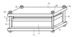
- FIG. 1 is a perspective view of a pressurizing structure for a storage battery according to the first embodiment.
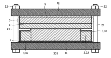
- FIG. 2 is a cross-sectional view of the pressurizing structure of the storage battery of the first embodiment.
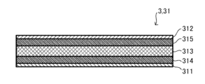
- FIG. 3 is a cross-sectional view showing an example of an electrode portion that constitutes the pressurizing structure of the storage battery of the first embodiment.
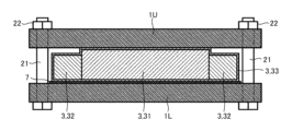
- FIG. 4 is a cross-sectional view of the pressurizing structure of the storage battery of the first comparative example.
- FIG. 5 is a cross-sectional view of a pressurizing structure for a storage battery of a second comparative example.
- FIG. 6 is a cross-sectional view of a pressurizing structure for a storage battery of a third comparative example.
- FIG. 1 is a perspective view of a pressurizing structure for a storage battery according to the first embodiment.
- FIG. 2 is a cross-sectional view of the pressurizing structure of the storage battery of the first embodiment.
- FIG. 3 is a cross-section
- FIG. 7 is a plan view showing the arrangement for measuring the surface pressure distribution of the electrode portion.
- FIG. 8A is a diagram showing the surface pressure distribution applied to the electrode portion of the first embodiment;
- FIG. 8B is a diagram showing the surface pressure distribution applied to the electrode portion of the first comparative example.
- FIG. 8C is a diagram showing the surface pressure distribution applied to the electrode portion of the second comparative example.
- FIG. 8D is a diagram showing the surface pressure distribution applied to the electrode portion of the third comparative example.
- FIG. 9A is a diagram showing a procedure for quantitative evaluation of the surface pressure distribution, and is a diagram showing division of a portion pressed by the electrode portion of the pressure-sensitive paper into a plurality of areas.
- FIG. 9B is a diagram showing a procedure for quantitatively evaluating the surface pressure distribution, in which the surface pressure is calculated for each area, and the average surface pressure of the entire area is calculated from the surface pressure of each area.
- FIG. 10 is a table showing quantitative evaluation of surface pressure distributions of Comparative Example 1-3 and Example 1-3.
- FIG. 11 is a table showing quantitative evaluation of the surface pressure distribution of Examples 3-7.
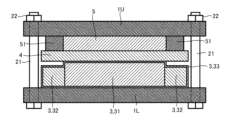
- FIG. 12 is a cross-sectional view of the pressurizing structure of the storage battery of the second embodiment.
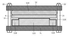
- FIG. 13 is a cross-sectional view of the pressurizing structure of the storage battery of the third embodiment.
- 14 is a table showing quantitative evaluation of surface pressure distributions of Examples 4-6 and Comparative Example 4.
- FIG. 10 is a table showing quantitative evaluation of surface pressure distributions of Comparative Example 1-3 and Example 1-3.
- FIG. 11 is a table showing quantitative evaluation of the surface pressure distribution of Examples 3-7.
- FIG. 12 is a cross-sectional view of the pressurizing structure of the storage
- FIG. 1 is a perspective view of a pressurizing structure for a storage battery according to the first embodiment.
- FIG. 2 is a cross-sectional view of the pressurizing structure of the storage battery of the first embodiment.
- FIG. 3 is a cross-sectional view showing an example of the electrode portion 31 that constitutes the pressurizing structure of the storage battery of the first embodiment.
- the storage battery cell 3 structure or the A laminate (structure) in which a plurality of storage battery cells 3 are laminated is sandwiched. Furthermore, an elastic body 5 and a rigid body 4 are sandwiched between the structure and the end plate 1U. The rigid body 4 is in contact with the storage battery cell 3, and the elastic body 5 is in contact with the end plate 1U.
- the storage battery cell 3 is, for example, an all-solid-state battery, and includes an electrode portion 31, an insulating layer 32 disposed on the outer periphery of the electrode portion 31 and protecting the outer periphery of the electrode portion 31, and a package of the electrode portion 31 and the insulating layer 32. and a covering material 33 to which a ring is applied.
- the end plate 1U and the end plate 1L are fastened together by fastening means (fastening bolts 21 and nuts 22).
- the fastening means (fastening bolt 21 and nut 22) are arranged so as to have central symmetry with respect to the electrode portion 31 in plan view (see FIG. 7). Although four fastening means (fastening bolts 21 and nuts 22) are arranged in FIGS. 1 and 2, more than four fastening means may be provided.
- the end plates 1U and 1L press the storage battery cell 3, the elastic body 5, and the rigid body 4 from the thickness direction, and the storage battery cell 3 is held on a predetermined surface. Apply pressure.
- the rigid body 4 is arranged so that its outer shape in plan view accommodates the storage battery cell 3 (especially the electrode portion 31) inside, and the main surface of the rigid body 4 on the storage battery cell 3 side is the storage battery. It is in surface contact with the cell 3 (especially the electrode part 31).
- a recess 41 (deformation suppressing means) is formed on the main surface of the rigid body 4 on the end plate 1U side, and the elastic body 5 is fitted into the recess 41 .
- the recessed portion 41 has an opening and an inner wall that follow the outer shape (rectangular) of the elastic body 5 in plan view and are slightly smaller than the outer shape of the elastic body 5 in plan view.
- a highly rigid material such as stainless steel (SUS304) is applied as the rigid body 4 (same for the end plate 1U and the end plate 1L).
- the elastic body 5 is made of a material having at least a lower elastic modulus (Young's modulus) than that of the rigid body 4 and a higher elastic limit than that of the rigid body 4, preferably silicone rubber 70°.
- Other materials for the elastic body 5 include silicone rubber 90°, polymethyl methacrylate (PMMA), polyethylene terephthalate (PET), Kapton (registered trademark), epoxy resin, polypropylene (PP), and polytetrafluoroethylene (PTFE). , rubber (natural rubber, synthetic rubber), etc. can be applied.
- an appropriate surface pressure for example, 4 MPa or more is applied from the thickness direction to improve the electrical conductivity and lithium ion conduction. It is necessary to suppress the decrease in degree.
- the elastic body 5 has the role of equalizing the pressing force from the end plate 1U (end plate 1L). However, when the elastic body 5 receives a pressing force from the end plate 1U (end plate 1L), it deforms in the surface direction (the direction perpendicular to the thickness direction), and the surface pressure applied to the storage battery cell 3 side is reduced by the amount of deformation. .
- the elastic body 5 is fitted in the recess 41 .
- the deformation of the elastic body 5 in the surface direction is suppressed, and the role of increasing the efficiency of transmitting the pressing force applied to the elastic body 5 to the rigid body 4 and the storage battery cell 3 is accordingly.
- the thickness of the elastic body 5 exposed from the rigid body 4 is preferably thinner than the thickness of the elastic body 5 fitted into the recess 41 . Thereby, deformation of the elastic body 5 in the surface direction can be effectively suppressed.
- the insulating layer 32 may be lower than the electrode portion 31 , and a step is formed between the electrode portion 31 and the insulating layer 32 . Therefore, when the elastic body 5 is directly pressed against the storage battery cell 3, the elastic body 5 is deformed following the shape of the step, and the surface pressure applied to the electrode portion 31 is increased to the outer peripheral side of the electrode portion 31 accordingly. It becomes a distribution that decreases as it goes.
- the rigid body 4 is arranged between the elastic body 5 and the storage battery cell 3, and the rigid body 4 deforms in the thickness direction of the portion of the elastic body 5 outside the outer shape of the electrode portion 31 in plan view. can be suppressed. Thereby, the uniformity of the surface pressure applied to the electrode part 31 can be improved.
- the elastic body 5 may be divided into a plurality of parts in the plane direction, but it is preferable to arrange them so as to be centrally symmetrical about the electrode part 31 in plan view.
- a plurality of concave portions 41 are also arranged based on the arrangement of the electrode portions 31 .
- the recess 41 may be formed in the end plate 1U instead of the rigid body 4. Also, the recess 41 may be formed in the rigid body 4 and the end plate 1U, respectively. In this case, the thickness of the elastic body 5 is set to be larger than the sum of the depth of the recess 41 formed in the rigid body 4 and the depth of the recess 41 formed in the end plate 1U.
- the electrode part 31 is a laminate in which a positive collector foil 311, a positive electrode layer 314, a solid electrolyte layer 313, a negative electrode layer 315, and a negative collector foil 312 are laminated in this order. Moreover, as the electrode part 31, the thing which laminated
- the positive current collector foil 311 is a thin plate made of metal such as aluminum (Al).
- the negative electrode current collector foil 312 is a thin plate made of metal such as stainless steel (SUS) or copper (Cu). External electrodes electrically connected to the exterior of the exterior material 33 are connected to the positive current collector foil 311 and the negative current collector foil 312 , respectively.
- the solid electrolyte layer 313 is a layer containing a solid electrolyte as a main component and interposed between the positive electrode layer 314 and the negative electrode layer 315 .
- solid electrolyte materials include sulfide solid electrolytes and oxide solid electrolytes, and sulfide solid electrolytes are preferred.
- Suitable sulfide solid electrolytes include, for example, lithium phosphorus sulfide compounds (eg, aldirodite (Li 6 PS 5 Cl)) and LGPS-based materials (eg, Li 10 GeP 2 S 12 ).
- the positive electrode layer 314 preferably contains a positive electrode active material containing sulfur.
- the type of the positive electrode active material containing sulfur is not particularly limited, but examples thereof include elemental sulfur (S) and particles or thin films of organic sulfur compounds or inorganic sulfur compounds. Any material may be used as long as it can release lithium ions at times and absorb lithium ions during discharge.
- the negative electrode layer 315 is composed of a negative electrode active material containing at least lithium metal or a lithium alloy.
- any material can be used as long as it can absorb lithium ions during charging and release lithium ions during discharging.
- the negative electrode layer 315 absorbs lithium ions conducted from the positive electrode layer 314 side as lithium metal, thereby increasing its thickness. The thickness is reduced by releasing it to the side.
- the insulating layer 32 is arranged in a frame shape that encircles the outer periphery of the electrode portion 31 .
- ultraviolet curable resin such as Aronix (registered trademark) and Aronoxetane (registered trademark) can be applied.
- Thermosetting resins such as polyethylene terephthalate (PET) and epoxy resin, can also be used as the material of the insulating layer 32 .
- Kapton registered trademark
- PTFE polytetrafluoroethylene
- rubber natural rubber, synthetic rubber
- FIG. 4 is a cross-sectional view of the pressurizing structure of the storage battery of the first comparative example.
- FIG. 5 is a cross-sectional view of a pressurizing structure for a storage battery of a second comparative example.
- FIG. 6 is a cross-sectional view of a pressurizing structure for a storage battery of a third comparative example.
- FIG. 7 is a diagram showing an arrangement for measuring the surface pressure distribution of the electrode portion 31.
- FIG. 8A is a diagram showing the surface pressure distribution applied to the electrode portion 31 of the first embodiment.
- FIG. 8B is a diagram showing the surface pressure distribution applied to the electrode portion 31 of the first comparative example.
- FIG. 8C is a diagram showing the surface pressure distribution applied to the electrode portion 31 of the second comparative example.
- FIG. 8D is a diagram showing the surface pressure distribution applied to the electrode portion 31 of the third comparative example.
- the inventor of the present application examined the surface pressure distribution of the electrode portion 31 in the pressurizing structure of the storage battery of the first embodiment while comparing it with the first to third comparative examples.
- the surface pressure distribution was confirmed by the following procedure.
- end plate 1U and the end plate 1L are fastened by fastening means (fastening bolts 21 and nuts 22), and the storage battery cells 3, rigid bodies 4, and elastic bodies 5 are pressed.
- a torque wrench is used to tighten the fastening means (fastening bolt 21, nut 22), and as shown in FIG. Tighten by the amount of rotation (for example, 45 degrees).
- the fastening means fastening bolt 21, nut 22
- the pressure sensitive paper 7 is taken out, and the surface pressure is confirmed.
- the electrode portion 31 of the storage battery cell 3 has a rectangular shape of 20 mm ⁇ 20 mm in plan view
- the rigid body 4 For example, SUS304
- the elastic body 5 (for example, silicone rubber 70°) has a thickness of 2 mm and a rectangular shape of 20 mm ⁇ 20 mm in plan view.
- the recess 41 has a depth of about 1.5 mm and a rectangular shape of 20 mm ⁇ 20 mm in plan view. Therefore, the elastic body 5 is exposed from the recess 41 (rigid body 4) by about 0.5 mm before pressing.
- SUS304 used as the rigid body 4 is PARNN-25-25-3-CSC manufactured by Misumi (dimensions: 3 ⁇ 25 ⁇ 25, surface polishing Ra: 0.4 to 1.4 ⁇ m, flatness of 0 for a length of 100 mm). 0.05 mm, parallelism: 0.012 mm, full circumference thread chamfer) was applied.
- SR-70T manufactured by Tigers Polymer Co., Ltd. (dimensions: 3 ⁇ 25 ⁇ 25, tolerance: ⁇ 0.25 mm, uneven thickness: ⁇ 0.35 mm) was applied to the silicone rubber 70° used as the elastic body 5. .
- the pressurizing structure of the storage battery of the first comparative example shown in FIG. 4 differs from the first embodiment in that there is no concave portion 41, and the elastic body 5 is sandwiched between the rigid body 4 and the end plate 1U. .
- the elastic body 5 (before pressurization) has a thickness of 3 mm and a rectangular shape of 25 mm x 25 mm in plan view. do.
- the pressurizing structure of the storage battery of the second comparative example shown in FIG. 5 differs from the first embodiment in that there is no rigid body 4 (concave portion 41), and the elastic body 5 is sandwiched between the storage battery cell 3 and the end plate 1U. It is configured.
- the elastic body 5 (before pressure) has a thickness of 3 mm and a rectangular shape of 25 mm x 25 mm in plan view. It expands and deforms so that the portion outside the electrode portion 31 in plan view curves toward the storage battery cell 3 side.
- the pressure-sensitive paper 7 is colored so that the outer shape of the electrode portion 31 is transferred, and the degree of coloring is substantially uniform (
- the surface pressure on the electrode portion 31 also has a substantially uniform coloring distribution.
- the elastic body 5 equalizes the pressing force from the end plate 1U in the plane direction, and the elastic body 5 is fitted into the concave portion 41 to suppress expansion of the elastic body 5 in the plane direction. This reduces diffusion of the pressing force applied to the elastic body 5 in the surface direction, and the surface pressure corresponding to the pressing force from the end plate 1U can be applied to the entire electrode portion 31 accordingly.
- the pressure-sensitive paper 7 is colored so that the outer shape of the electrode portion 31 is transferred, and the degree of coloring is almost uniform ( The surface pressure on the electrode portion 31 is also substantially uniform), but the degree of coloring is lighter than that shown in FIG. 8A.
- the elastic body 5 when the elastic body 5 receives a pressing force in the thickness direction, it expands in the plane direction as indicated by the broken line, and the pressing force applied to the rigid body 4 and the storage battery cell 3 decreases accordingly. due to
- the pressure-sensitive paper 7 is colored in a state where the outer shape of the electrode section 31 is ambiguous, and the portion facing the center of the electrode section 31 is colored. It has a coloring distribution in which the coloring becomes lighter toward the outside. This is because, as shown in FIG. 5, when the elastic body 5 receives a pressing force, it expands in the plane direction as indicated by the broken line, and the portion arranged outside the electrode portion 31 in plan view becomes the storage battery cell. 3, and since this portion does not receive compressive stress, the pressing force received by the portion overlapping the electrode portion 31 in plan view of the elastic body 5 moves toward the outer periphery as it approaches the outer periphery of the electrode portion 31. This is due to the large diffusion of
- the pressure-sensitive paper 7 is colored so that the outer shape of the electrode portion 31 is transferred, it is extremely darkly colored in a specific peripheral portion. and has a coloring distribution in which the other peripheral edge portions opposite to the specific peripheral edge portion are hardly colored. This is because the main surface of the end plate 1U on the electrode portion 31 side and the main surface of the electrode portion 31 are not completely parallel to each other, and the main surface of the end plate 1U is inclined with respect to the main surface of the electrode portion 31. This is because the end plate 1U presses the electrode portion 31 in the state where the end plate 1U is pressed.
- FIG. 9A is a diagram showing the procedure of quantitative evaluation of the surface pressure distribution, and is a diagram of dividing the portion pressed by the electrode portion 31 of the pressure-sensitive paper 7 into a plurality of areas.
- FIG. 9B is a diagram showing a procedure for quantitatively evaluating the surface pressure distribution, in which the surface pressure is calculated for each area, and the average surface pressure of the entire area is calculated from the surface pressure of each area.
- FIG. 10 is a table showing quantitative evaluation of surface pressure distributions of Comparative Example 1-3 and Example 1-3.
- the surface pressure distribution of the electrode portion 31 is quantitatively evaluated based on the coloring distribution formed on the pressure-sensitive paper 7 .
- the portion where the surface pressure of the electrode portion 31 of the pressure-sensitive paper 7 is transferred is divided into a plurality of portions (16 portions in FIGS. 9A and 9B).
- Examples 1-3 shown in FIG. 10 all have the configuration of FIG. Therefore, the dimensional retention rates in the plane direction of Examples 1-3 are all 100% (no change).
- the rigid body 4 of Example 1-3 uses SUS304 (thickness: 3 mm, maximum deflection: 0.01 mm), and is deformed at least by the set pressure (5 MPa) of the fastening means (fastening bolt 21, nut 22). do not.
- Example 1-3 the tightening torque of the fastening means and the set pressure (pressing force) applied to the electrode portion 31 side are changed.
- Example 1 the torque was set to 0.32 Nm and the set pressure (pressing force) was set to 1.5 Mpa.
- the average surface pressure was 1.42 MPa
- the surface pressure difference was 0.5 MPa
- the surface pressure retention rate was 95%
- the surface pressure difference/average surface pressure was 35%.
- Example 2 the torque was set to 0.64 Nm, and the set pressure (pressing force) was set to 3 Mpa.
- the average surface pressure was 2.9 MPa
- the surface pressure difference was 0.98 MPa
- the surface pressure retention rate was 97%
- the surface pressure difference/average surface pressure was 34%.
- Example 3 the torque was set to 1.06 Nm, and the set pressure (pressing force) was set to 5 Mpa.
- the average surface pressure was 4.81 MPa
- the surface pressure difference was 1.75 MPa
- the surface pressure retention rate was 96%
- the surface pressure difference/average surface pressure was 36%.
- the surface pressure difference is the difference between the maximum surface pressure and the minimum surface pressure among the surface pressures of the plurality of areas shown in FIG.
- the surface pressure maintenance rate is the surface pressure average/set pressure (accuracy of the set pressure applied to the electrode portion 31), and it can be said that the closer to 100%, the more uniform the surface pressure distribution. In addition, it can be said that the lower the value of the difference in surface pressure/average surface pressure, the less variation in the surface pressure distribution and the better.
- Example 1-3 the average surface pressure and the surface pressure difference are proportional to the torque and the set pressure, but the surface pressure retention rate and the surface pressure difference/average surface pressure are substantially constant.
- the surface pressure distribution is substantially uniform as shown in FIG. 8A. ), it can be said that the surface pressure distribution in the electrode portion 31 does not change significantly and is stable.
- the thickness of the storage battery cell 3 electrode portion 31
- the thickness of the storage battery cell 3 changes with charging and discharging, it is considered that even if the thickness changes in this way, the surface pressure distribution does not change significantly. Therefore, according to the first embodiment (FIG. 2), it is possible to stably form a good surface pressure distribution, and reduce variations in capacity and output of the storage battery cells 3 .
- Comparative Example 1 has the configuration shown in FIG. In this case, the torque was set to 0.32 Nm, and the set pressure (pressing force) was set to 3 MPa. As a result, in Comparative Example 1, the average surface pressure was 3.9 MPa, the surface pressure difference was 2.95 MPa, the surface pressure retention rate was 130%, and the surface pressure difference/average surface pressure was 76%.
- Comparative Example 1 the average surface pressure is higher than the set pressure, and the surface pressure retention rate is a high value exceeding 100%. This is because, in Comparative Example 1, as shown in FIG. 8D , the surface pressure is applied extremely strongly to the specific peripheral edge portion, and the surface pressure is hardly applied to the other peripheral edge portion opposite to the specific peripheral edge portion. This is due to the pressure distribution. Further, in Comparative Example 1, even if the torque and the set pressure were changed, the tendency of the surface pressure distribution did not change. Therefore, in Comparative Example 1, it is difficult to apply a uniform surface pressure to the entire electrode portion 31, and sufficient capacity and output of the storage battery cell 3 cannot be obtained.
- Comparative Examples 2 and 3 have the configuration of FIG. 4, that is, the configuration without deformation suppressing means (recesses 41) for suppressing deformation of the elastic body 5 in the plane direction.
- silicone rubber 70° was applied as the elastic body 5 .
- the torque was set to 0.64 Nm and the set pressure was set to 3 MPa.
- the torque was set to 1.06 and the set pressure was set to 5 MPa.
- Comparative Example 2 the average surface pressure was 2.2 MPa, the surface pressure difference was 1.4 MPa, the surface pressure retention rate was 73%, and the surface pressure difference/average surface pressure was 64%. In Comparative Example 3, the average surface pressure was 3 MPa, the surface pressure difference was 2.5 MPa, the surface pressure retention rate was 60%, and the surface pressure difference/average surface pressure was 83%.
- both the surface pressure retention rates are greatly reduced from 100%. This is because, as shown in FIG. 8C, in the elastic body 5, the component of the pressing force received from the end plate 1U side that escapes outward in the surface direction increases toward the outer peripheral side.
- the surface pressure retention rate decreased and the surface pressure difference/surface pressure average increased. This is because when the torque and the set pressure are increased, the tendency of the surface pressure distribution between the elastic body 5 and the rigid body 4 shown in FIG. 8C becomes more pronounced. Therefore, in Comparative Examples 2 and 3, although a uniform surface pressure can be applied to the electrode portion 31, the capacity and output of the storage battery cell 3 may fluctuate due to changes in torque and set pressure. A change in the thickness direction associated with charge/discharge of the (electrode portion 31) may also cause fluctuations in capacity and output, and the operation of the storage battery cell 3 becomes unstable.
- Example 1-3 (FIG. 2)
- the elastic body 5 is compressed in a manner of sinking toward the recess 41 when pressed from the end plate 1U. Therefore, the expansion in the surface direction of the portion of the elastic body 5 exposed from the concave portion 41 is also suppressed by the amount of sinking. Also, the portion of the elastic body 5 that is sunk and fitted into the concave portion 41 does not expand in the planar direction.
- FIG. 11 is a table showing quantitative evaluation of the surface pressure distribution of Examples 3-7.
- Example 3-7 is a quantitative evaluation of the surface pressure distribution when the material of the elastic body 5 is changed in the configuration of the first embodiment shown in FIG.
- Example 3 silicone rubber 70° (elastic modulus (elastic modulus at which the compressive strain is 5 to 10% at a compressive pressure of 5 MPa, the same shall apply hereinafter): 3.3 MPa) is applied as the elastic body 5.
- Example 4 uses natural rubber (elastic modulus: 2.9 MPa)
- Example 5 uses silicone rubber 90° (elastic modulus: 12 MPa)
- Example 6 uses polypropylene (PP , elastic modulus (flexural strength): 37 MPa)
- Example 7 uses 30% polyethylene terephthalate glass (PET-GF30, containing 30% glass, elastic modulus (compressive strength): 173 MPa).
- PET-GF30 polyethylene terephthalate glass
- the dimensions of the elastic body 5 applied to Examples 4-7 are the same as those of Example 3 (3 mm x 25 mm x 25 mm).
- the torque and set pressure applied to Examples 4-7 are also the same as those of Example 3 (torque: 1.06, set pressure: 5 MPa).
- Example 4 the average surface pressure was 4.7 MPa, the surface pressure difference was 1.8 MPa, the surface pressure retention rate was 94%, and the surface pressure difference/surface pressure average was 38%.
- Example 5 the average surface pressure was 4.85 MPa, the surface pressure difference was 2.2 MPa, the surface pressure retention rate was 97%, and the surface pressure difference/average surface pressure was 45%.
- Example 6 the average surface pressure was 4.91 MPa, the surface pressure difference was 2.3 MPa, the surface pressure retention ratio was 98%, and the surface pressure difference/average surface pressure was 47%.
- Example 7 the average surface pressure was 4.93 MPa, the surface pressure difference was 2.4 MPa, the surface pressure retention rate was 99%, and the surface pressure difference/average surface pressure was 49%.
- Example 3-7 As shown in Example 3-7, as the elastic modulus of the elastic body 5 increases, the average surface pressure, the surface pressure difference, the surface pressure retention rate, and the surface pressure difference/average surface pressure increase, but the rate of increase is slight. Further, the surface pressure retention rate of Example 4, which has the lowest elastic modulus among Examples 4-7, achieves 94%. Further, in Example 7, which has the highest elastic modulus among Examples 3-7, the surface pressure difference/surface pressure average is 49%, but the elastic modulus is 99%.
- the elastic body 5 has an elastic modulus such that the compressive strain is 5 to 10% with respect to the set pressure (5 Mpa), it will not be completely buried in the concave portion 41 when compressed, and the surface pressure distribution in the electrode portion 31 will be reduced. can be made uniform.
- any material can be applied to the elastic body 5 as long as it has an elastic modulus in the range of 0.5 MPa to 200 MPa. Further, when considering Example 7, the difference between the surface pressure applied to the central portion of the electrode portion 31 and the surface pressure applied to the peripheral portion of the elastic body 5 is 2.4 MPa or less (largely estimated, 3.0 MPa or less). Materials are preferred.
- a structure composed of the storage battery cell 3 including the electrode portion 31 packaged with the laminated exterior material (the exterior material 33), or a plurality of the storage battery cells 3 are laminated
- a pressurizing structure of a storage battery that presses a structure composed of a laminated body from the thickness direction, and a pair of end plates (end plate 1U, end plate 1U, end plate 1L) and a fastening member (fastening bolt 21, nut 22) for fastening a pair of end plates (end plate 1U, end plate 1L) to each other, and end plate (end plate 1U, end plate 1L) and structure
- An elastic body 5 is arranged at least at a position sandwiched between bodies (eg, storage battery cells 3), a rigid body 4 is arranged at a position sandwiched between the elastic body 5 and a structural body (eg, storage battery cells 3), and an end plate. (End plate 1U, end plate 1L), elastic
- the elastic body 5 uniforms the distribution of the pressing force of the fastening means (fastening bolt 21, nut 22) via the end plates (end plate 1U, end plate 1L), and the deformation suppressing means (for example, by suppressing the expansion of the elastic body 5 in the plane direction by the recess 41), it is possible to suppress the diffusion of the pressing force of the elastic body 5 in the plane direction, and the rigid body 4 prevents deformation of the elastic body 5 in the thickness direction. By suppressing, it becomes possible to uniformly and appropriately apply pressure to the storage battery cells 3 (especially the electrode portions 31).
- the deformation suppressing means is a recess 41 formed in the rigid body 4 and/or the end plate (end plate 1U, end plate 1L) and into which the outer periphery of the elastic body 5 is fitted.
- the deformation suppressing means can be realized with a simple configuration.
- the portion of the elastic body 5 that is fitted into the concave portion 41 does not expand in the plane direction due to the pressing force from the end plate (end plate 1U, end plate 1L) side, and the pressing force is applied to the storage battery cell 3 in the plane direction. It can be reliably transmitted as pressure.
- FIG. 12 is a cross-sectional view of the pressurizing structure of the storage battery of the second embodiment.
- FIG. 13 is a cross-sectional view of the pressurizing structure of the storage battery of the third embodiment.
- the deformation suppressing means is arranged so as to cover the outer periphery of the elastic body 5 in plan view, and is made of a material having a higher elastic modulus than the elastic body 5.
- the outer peripheral portion 51 is formed.
- the outer peripheral portion 51 is made of polymethyl methacrylate resin (PMMA, elastic modulus (bending strength): 125 MPa), polytetrafluoroethylene A resin (PTFE, elastic modulus (compressive strength): 11.8 Mpa) or the like is suitable.
- PMMA polymethyl methacrylate resin
- PTFE polytetrafluoroethylene A resin
- PTFE elastic modulus (compressive strength): 11.8 Mpa
- ABS acrylonitrile butadiene styrene
- PC polycarbonate
- POM polyoxymethylene
- PPS polyphenylene sulfide
- PET polyethylene terephthalate
- PEEK polyetheretherketone
- the deformation suppressing means is a fibrous material (reinforcing cloth 52) arranged inside the elastic body 5 in a mesh pattern.
- the reinforcing cloth 52 is a material formed by weaving fibers such as nylon, fluorocarbon, polyethylene, etc., and has high tensile strength.
- the elastic body 5 (composite elastic body) containing the reinforcing cloth 52 is formed, for example, by impregnating the reinforcing cloth 52 with a natural rubber material and then vulcanizing the material.
- the elastic body 5 containing the reinforcing cloth 52 is made by impregnating the reinforcing cloth 52 with a thermosetting resin material and then thermally curing it, or by impregnating the reinforcing cloth 52 with an ultraviolet-curable resin material and then irradiating it with ultraviolet rays. and hardening.
- the reinforcing cloth 52 suppresses expansion of the elastic body 5 in the surface direction. ) can suppress a decrease in the surface pressure applied to.
- FIG. 14 is a table showing quantitative evaluation of surface pressure distributions of Examples 4-6 and Comparative Example 4. Quantitative evaluation of the surface pressure distribution was also performed for the second embodiment and the third embodiment.
- Examples 8 and 9 have the configuration of the second embodiment shown in FIG. Regarding the outer peripheral portion 51, in Example 8, polymethyl methacrylate resin (PMMA, elastic modulus (flexural strength): 125 Mpa) is applied, and in Example 9, polytetrafluoroethylene resin (PTFE, elastic modulus (compressive strength) ): 11.8 MPa) was applied.
- PMMA polymethyl methacrylate resin
- PTFE polytetrafluoroethylene resin
- the dimensions of the elastic body 5 are the same as those of the elastic body 5 of Comparative Example 1 (3 mm x 25 mm x 25 mm), and the torque and set pressure are the same as those of Example 3-7.
- the elastic body 5 is not fitted into the recess 41 unlike the first embodiment.
- the outer periphery of the elastic body 5 is covered with an outer peripheral portion 51 having a higher elastic modulus than the elastic body 5, and the outer peripheral portion 51 limits the expansion of the elastic body 5 in the plane direction. Therefore, in Examples 8 and 9 (second embodiment), the dimensional retention rate of the elastic body 5 in the surface direction is 100%.
- Example 8 the average surface pressure was 4.3 MPa, the surface pressure difference was 1.81 MPa, the surface pressure maintenance rate was 86%, and the surface pressure difference/surface pressure average was 42%.
- Example 9 the average surface pressure was 4.2 MPa, the surface pressure difference was 1.92 MPa, the surface pressure retention ratio was 84%, and the surface pressure difference/average surface pressure was 46%.
- the material of the outer peripheral portion 51 (PMMA (elastic modulus: 125 MPa)) used in Example 8 and the material of the outer peripheral portion 51 (PTFE (elastic modulus: 11.8 MPa)) used in Example 9 differ greatly in elastic modulus. However, no significant difference was observed in the surface pressure retention rate and the surface pressure difference/surface pressure average between Examples 8 and 9, and the surface pressure retention rate exceeded 80% in both cases.
- PMMA elastic modulus: 125 MPa
- PTFE elastic modulus: 11.8 MPa
- the elastic modulus of the outer peripheral portion 51 is sufficiently larger than the elastic modulus of the elastic body 5, a large difference in the surface pressure retention ratio and the surface pressure difference/average surface pressure does not occur, and the surface pressure is high. It is possible to maintain the retention rate. Therefore, even in the pressurizing structure of the storage battery of the second embodiment, it is possible to stably achieve a uniform and appropriate surface pressure distribution on the electrode portion 31, and to reduce variations in capacity and output of the storage battery cells 3.
- Example 10 has the configuration of the third embodiment shown in FIG. 13, and a natural rubber sheet containing reinforcing cloth 52 is applied as the elastic body 5 containing reinforcing cloth 52 .
- Comparative Example 4 uses a natural rubber sheet without reinforcing cloth 52, and has substantially the same configuration as Comparative Example 1 (Fig. 4).
- the dimensions of the elastic body 5 are the same as those of the elastic body 5 of Comparative Example 1 (3 mm x 25 mm x 25 mm), and the torque and set pressure are the same as those of Example 3-7.
- Example 10 unlike the first embodiment, the elastic body 5 is not fitted into the recess 41 . However, a reinforcing cloth 52 is arranged inside the elastic body 5, and the reinforcing cloth 52 limits the expansion of the elastic body 5 in the plane direction. Therefore, in Example 10 (first embodiment), the dimensional retention rate of the elastic body 5 in the surface direction is 110%. On the other hand, in Comparative Example 4, since there is no reinforcing cloth 52, the elastic body 5 expands in the planar direction due to the pressing force from the end plate 1U, and the dimensional retention rate in the planar direction is 120%.
- Example 10 the average surface pressure was 4 MPa, the surface pressure difference was 1.9 MPa, the surface pressure retention rate was 80%, and the surface pressure difference/surface pressure average was 48%.
- Comparative Example 4 the average surface pressure was 3.2 MPa, the surface pressure difference was 2.6 MPa, the surface pressure retention rate was 64%, and the surface pressure difference/average surface pressure was 81%.
- Example 10 the surface pressure retention rate was 80%, which is lower than that of Example 1-9, but the surface pressure difference was 1.9 MPa, and Example 5-7 (Fig. 11) and It is better than Example 9.
- the dimensional retention rate of the elastic body 5 in the plane direction is 110%, but the reinforcing cloth 52 hardly expands in the plane direction due to the pressing force from the end plate 1U. As a result, expansion of the elastic body 5 in the plane direction is also suppressed. Therefore, the surface pressure difference and the surface pressure retention rate do not change significantly due to changes in torque and set pressure, and changes in thickness due to charging and discharging of the storage battery cells 3 . Therefore, Example 10, that is, the third embodiment (FIG. 13) can stably form a uniform and appropriate surface pressure distribution, and can reduce variations in capacity and output of the storage battery cells 3 .
- Comparative Example 4 there is no means for suppressing the expansion of the elastic body 5 in the surface direction, and the surface pressure difference and the surface pressure maintenance rate increase due to changes in torque and set pressure, and changes in thickness accompanying charging and discharging of the storage battery cell 3. can vary greatly. Therefore, in Comparative Example 4, it is difficult to form a favorable surface pressure distribution, and it is also difficult to reduce variations in capacity and output of the storage battery cells 3 .
Landscapes
- Chemical & Material Sciences (AREA)
- Chemical Kinetics & Catalysis (AREA)
- Electrochemistry (AREA)
- General Chemical & Material Sciences (AREA)
- Engineering & Computer Science (AREA)
- Manufacturing & Machinery (AREA)
- Mechanical Engineering (AREA)
- Secondary Cells (AREA)
- Electric Double-Layer Capacitors Or The Like (AREA)
- Sealing Battery Cases Or Jackets (AREA)
Priority Applications (4)
| Application Number | Priority Date | Filing Date | Title |
|---|---|---|---|
| JP2023554086A JP7718500B2 (ja) | 2021-10-21 | 2022-10-14 | 蓄電池の加圧構造 |
| US18/702,633 US20240347759A1 (en) | 2021-10-21 | 2022-10-14 | Pressurizing Structure for Storage Battery |
| CN202280070711.9A CN118140348A (zh) | 2021-10-21 | 2022-10-14 | 蓄电池的加压构造 |
| EP22883037.8A EP4421959A4 (en) | 2021-10-21 | 2022-10-14 | STORAGE BATTERY PRESSURIZATION STRUCTURE |
Applications Claiming Priority (2)
| Application Number | Priority Date | Filing Date | Title |
|---|---|---|---|
| JP2021172698 | 2021-10-21 | ||
| JP2021-172698 | 2021-10-21 |
Publications (1)
| Publication Number | Publication Date |
|---|---|
| WO2023067383A1 true WO2023067383A1 (ja) | 2023-04-27 |
Family
ID=86058842
Family Applications (1)
| Application Number | Title | Priority Date | Filing Date |
|---|---|---|---|
| PCT/IB2022/000590 Ceased WO2023067383A1 (ja) | 2021-10-21 | 2022-10-14 | 蓄電池の加圧構造 |
Country Status (5)
| Country | Link |
|---|---|
| US (1) | US20240347759A1 (https=) |
| EP (1) | EP4421959A4 (https=) |
| JP (1) | JP7718500B2 (https=) |
| CN (1) | CN118140348A (https=) |
| WO (1) | WO2023067383A1 (https=) |
Cited By (2)
| Publication number | Priority date | Publication date | Assignee | Title |
|---|---|---|---|---|
| JP2026502660A (ja) * | 2023-10-30 | 2026-01-23 | エルジー エナジー ソリューション リミテッド | 電池セル加圧パッド及びこれを含む電池セル加圧装置 |
| JP2026503708A (ja) * | 2023-12-22 | 2026-01-29 | エルジー エナジー ソリューション リミテッド | 全固体電池の加圧評価方法及び加圧評価装置 |
Citations (5)
| Publication number | Priority date | Publication date | Assignee | Title |
|---|---|---|---|---|
| JP2005116445A (ja) * | 2003-10-10 | 2005-04-28 | Nissan Motor Co Ltd | 組電池 |
| JP2009099383A (ja) | 2007-10-17 | 2009-05-07 | Panasonic Corp | 積層体の加圧構造 |
| JP2012084332A (ja) * | 2010-10-08 | 2012-04-26 | Toyota Motor Corp | リチウムイオン二次電池の製造方法 |
| JP2017152338A (ja) * | 2016-02-26 | 2017-08-31 | 株式会社豊田自動織機 | 電池モジュール |
| JP2021172698A (ja) | 2020-04-21 | 2021-11-01 | 昭和電工マテリアルズ株式会社 | 硬化性組成物、蓄熱材、及び物品 |
Family Cites Families (2)
| Publication number | Priority date | Publication date | Assignee | Title |
|---|---|---|---|---|
| CN205564882U (zh) * | 2016-03-18 | 2016-09-07 | 宁德新能源科技有限公司 | 施压装置 |
| JP7174923B2 (ja) * | 2018-01-17 | 2022-11-18 | パナソニックIpマネジメント株式会社 | 蓄電装置 |
-
2022
- 2022-10-14 JP JP2023554086A patent/JP7718500B2/ja active Active
- 2022-10-14 WO PCT/IB2022/000590 patent/WO2023067383A1/ja not_active Ceased
- 2022-10-14 EP EP22883037.8A patent/EP4421959A4/en active Pending
- 2022-10-14 US US18/702,633 patent/US20240347759A1/en active Pending
- 2022-10-14 CN CN202280070711.9A patent/CN118140348A/zh active Pending
Patent Citations (5)
| Publication number | Priority date | Publication date | Assignee | Title |
|---|---|---|---|---|
| JP2005116445A (ja) * | 2003-10-10 | 2005-04-28 | Nissan Motor Co Ltd | 組電池 |
| JP2009099383A (ja) | 2007-10-17 | 2009-05-07 | Panasonic Corp | 積層体の加圧構造 |
| JP2012084332A (ja) * | 2010-10-08 | 2012-04-26 | Toyota Motor Corp | リチウムイオン二次電池の製造方法 |
| JP2017152338A (ja) * | 2016-02-26 | 2017-08-31 | 株式会社豊田自動織機 | 電池モジュール |
| JP2021172698A (ja) | 2020-04-21 | 2021-11-01 | 昭和電工マテリアルズ株式会社 | 硬化性組成物、蓄熱材、及び物品 |
Non-Patent Citations (1)
| Title |
|---|
| See also references of EP4421959A4 |
Cited By (2)
| Publication number | Priority date | Publication date | Assignee | Title |
|---|---|---|---|---|
| JP2026502660A (ja) * | 2023-10-30 | 2026-01-23 | エルジー エナジー ソリューション リミテッド | 電池セル加圧パッド及びこれを含む電池セル加圧装置 |
| JP2026503708A (ja) * | 2023-12-22 | 2026-01-29 | エルジー エナジー ソリューション リミテッド | 全固体電池の加圧評価方法及び加圧評価装置 |
Also Published As
| Publication number | Publication date |
|---|---|
| JP7718500B2 (ja) | 2025-08-05 |
| JPWO2023067383A1 (https=) | 2023-04-27 |
| EP4421959A1 (en) | 2024-08-28 |
| EP4421959A4 (en) | 2025-07-02 |
| CN118140348A (zh) | 2024-06-04 |
| US20240347759A1 (en) | 2024-10-17 |
Similar Documents
| Publication | Publication Date | Title |
|---|---|---|
| JP7148600B2 (ja) | 固体電池 | |
| CN100499205C (zh) | 紧凑的燃料电池堆栈结构 | |
| CN1246922C (zh) | 电池组件 | |
| WO2023067383A1 (ja) | 蓄電池の加圧構造 | |
| US20210296745A1 (en) | Battery pack production method and battery pack | |
| CN102347505B (zh) | 具备紧固部件的燃料电池堆 | |
| AU2016391240B2 (en) | Redox flow battery | |
| CN103545541B (zh) | 燃料电池 | |
| CN101904039B (zh) | 用于燃料电池组的压紧设备 | |
| KR20090035328A (ko) | 스웰링에 의한 극판 변형을 방지하는 구조의 극판 압착판을갖는 전극조립체 및 이를 이용한 전지 | |
| US7524573B2 (en) | Fuel cell having inner and outer periphery seal members | |
| EP4290598B1 (en) | Electrode manufacturing device | |
| US12057543B2 (en) | Battery cell manufacturing device | |
| US12334491B2 (en) | Battery cell jig that bolt-fastens through uniform pressure | |
| US20230006238A1 (en) | Fuel cell | |
| US11870088B2 (en) | Structural battery with pressure housing for portable electronic devices | |
| US20240421434A1 (en) | All-Solid-State Battery and Method for Manufacturing All-Solid-State Battery | |
| JP7815085B2 (ja) | 全固体電池 | |
| KR101592812B1 (ko) | 2차 전지 및 그 제작방법 | |
| CN220172264U (zh) | 电池模块和包括该电池模块的电池组 | |
| JP2025089150A (ja) | 蓄電池 | |
| JP2550482Y2 (ja) | 燃料電池 | |
| KR20230111156A (ko) | 전지팩 및 이를 포함하는 디바이스 | |
| CN120728152A (zh) | 蓄电池模组 | |
| CN119994302A (zh) | 换热组件、电池装置以及用电装置 |
Legal Events
| Date | Code | Title | Description |
|---|---|---|---|
| 121 | Ep: the epo has been informed by wipo that ep was designated in this application |
Ref document number: 22883037 Country of ref document: EP Kind code of ref document: A1 |
|
| ENP | Entry into the national phase |
Ref document number: 2023554086 Country of ref document: JP Kind code of ref document: A |
|
| WWE | Wipo information: entry into national phase |
Ref document number: 18702633 Country of ref document: US |
|
| WWE | Wipo information: entry into national phase |
Ref document number: 202280070711.9 Country of ref document: CN |
|
| WWE | Wipo information: entry into national phase |
Ref document number: 2022883037 Country of ref document: EP |
|
| NENP | Non-entry into the national phase |
Ref country code: DE |
|
| ENP | Entry into the national phase |
Ref document number: 2022883037 Country of ref document: EP Effective date: 20240521 |