WO2023063078A1 - 巻線欠陥検査装置、巻線欠陥検査装置を使用した電気機械の製造方法、及び巻線欠陥検査方法 - Google Patents
巻線欠陥検査装置、巻線欠陥検査装置を使用した電気機械の製造方法、及び巻線欠陥検査方法 Download PDFInfo
- Publication number
- WO2023063078A1 WO2023063078A1 PCT/JP2022/036142 JP2022036142W WO2023063078A1 WO 2023063078 A1 WO2023063078 A1 WO 2023063078A1 JP 2022036142 W JP2022036142 W JP 2022036142W WO 2023063078 A1 WO2023063078 A1 WO 2023063078A1
- Authority
- WO
- WIPO (PCT)
- Prior art keywords
- winding
- defect
- inspection
- unit
- signal
- Prior art date
- Legal status (The legal status is an assumption and is not a legal conclusion. Google has not performed a legal analysis and makes no representation as to the accuracy of the status listed.)
- Ceased
Links
Images







Classifications
-
- G—PHYSICS
- G01—MEASURING; TESTING
- G01R—MEASURING ELECTRIC VARIABLES; MEASURING MAGNETIC VARIABLES
- G01R31/00—Arrangements for testing electric properties; Arrangements for locating electric faults; Arrangements for electrical testing characterised by what is being tested not provided for elsewhere
- G01R31/50—Testing of electric apparatus, lines, cables or components for short-circuits, continuity, leakage current or incorrect line connections
- G01R31/58—Testing of lines, cables or conductors
- G01R31/59—Testing of lines, cables or conductors while the cable continuously passes the testing apparatus, e.g. during manufacture
-
- H—ELECTRICITY
- H01—ELECTRIC ELEMENTS
- H01F—MAGNETS; INDUCTANCES; TRANSFORMERS; SELECTION OF MATERIALS FOR THEIR MAGNETIC PROPERTIES
- H01F41/00—Apparatus or processes specially adapted for manufacturing or assembling magnets, inductances or transformers; Apparatus or processes specially adapted for manufacturing materials characterised by their magnetic properties
-
- H—ELECTRICITY
- H01—ELECTRIC ELEMENTS
- H01F—MAGNETS; INDUCTANCES; TRANSFORMERS; SELECTION OF MATERIALS FOR THEIR MAGNETIC PROPERTIES
- H01F41/00—Apparatus or processes specially adapted for manufacturing or assembling magnets, inductances or transformers; Apparatus or processes specially adapted for manufacturing materials characterised by their magnetic properties
- H01F41/02—Apparatus or processes specially adapted for manufacturing or assembling magnets, inductances or transformers; Apparatus or processes specially adapted for manufacturing materials characterised by their magnetic properties for manufacturing cores, coils, or magnets
- H01F41/04—Apparatus or processes specially adapted for manufacturing or assembling magnets, inductances or transformers; Apparatus or processes specially adapted for manufacturing materials characterised by their magnetic properties for manufacturing cores, coils, or magnets for manufacturing coils
- H01F41/06—Coil winding
-
- H—ELECTRICITY
- H02—GENERATION; CONVERSION OR DISTRIBUTION OF ELECTRIC POWER
- H02K—DYNAMO-ELECTRIC MACHINES
- H02K15/00—Processes or apparatus specially adapted for manufacturing, assembling, maintaining or repairing of dynamo-electric machines
- H02K15/04—Processes or apparatus specially adapted for manufacturing, assembling, maintaining or repairing of dynamo-electric machines of windings prior to their mounting into the machines
Definitions
- This application relates to a winding defect inspection device, an electric machine manufacturing method using the winding defect inspection device, and a winding defect inspection method.
- the insulation layer of the windings of a rotating electrical machine has flaws, pinholes, or other defects, the insulation between the windings and the winding core or between the windings and the ground will deteriorate, and the insulation next to the coils that form the windings will Insulation breakdown between matching windings may cause problems such as deterioration of the performance of the rotating electrical machine, burnout, or electrical leakage.
- Conventional winding defect inspection technology applies a voltage to electrodes placed around the winding, detects the discharge current or amount of charge between the winding and the electrode, and compares the magnitude with a threshold value. (See, for example, Patent Document 1).
- a sensor unit that receives a partial discharge signal and a noise signal generated by voltage application to a rotating machine, a synchronizing signal generating unit that generates a synchronizing signal synchronized with the cycle of the drive voltage of the rotating machine, and a sensor unit.
- an integration processing unit that integrates the sensor signal received in the period of the synchronization signal to generate an integrated waveform; a partial discharge detection unit that separates partial discharge and noise from the integrated waveform of the sensor signal and calculates the amount of partial discharge;
- a partial discharge detection device provided with a determination unit that determines abnormality of a rotating machine based on the amount of partial discharge (see, for example, Patent Document 2).
- Patent Document 1 a voltage is applied to electrodes arranged around the winding, the discharge current or charge amount of the running winding is detected, and the magnitude of the detection signal is used as a threshold value. It is possible to determine whether there is a defect in the winding by comparing with . There was a problem that the discharge current or the amount of charge could fluctuate greatly due to the swinging of the windings during running, making it impossible to determine the presence or absence of defects with high reliability.
- a sensor is placed on a stationary winding (a ready-made winding), inspection signals for a plurality of cycles are accumulated, and the accumulated detection signals are integrated or added. After performing processing such as matching, the magnitude of the processed signal can be compared with a threshold value to determine the presence or absence of defects in the windings. It takes a considerably long time, and there is a problem that it is not possible to inspect defects in running windings (for example, 500 mm/s) in real time.
- the present application discloses a technique for solving the above problems, and aims to determine the defect position of the winding during running with high accuracy and high reliability.
- the winding defect inspection device disclosed in the present application is A method for inspecting defects in a winding when winding a winding around a member to be wound to manufacture a winding component, a sensor arranged in the middle of a path from one end of the winding to the wound member; a discharge detection unit that detects a discharge current generated by a voltage applied between the sensor and the defective portion of the winding, a charge amount, or a change in the voltage; an accumulation unit for accumulating inspection signals output from the discharge detection unit; The inspection signal stored in the storage unit is assigned, and a computing unit is provided for calculating the time required to specify the defect position in the winding by analyzing the frequency characteristics of the inspection signal. .
- a method of manufacturing an electric machine using a winding defect inspection apparatus disclosed in the present application includes winding a winding, which has been confirmed to have no insulation defect using the winding defect inspection apparatus, around a stator core. manufactures an electrical machine with a stator core.
- the winding defect inspection method disclosed in the present application includes a sensor arranged in the middle of the path from one end of the winding to the wound member; a discharge detection unit that detects a discharge current generated by a voltage applied between the sensor and the defective portion of the winding, a charge amount, or a change in the voltage; an accumulation unit for accumulating inspection signals output from the discharge detection unit; By providing a plurality of calculators that perform calculations based on the inspection signals accumulated in the accumulation unit, defects in the winding when the winding is wound around the wound member to manufacture a winding component.
- a winding defect inspection method for inspecting the The accumulation unit accumulates the inspection signal over a certain period of time, and assigns the accumulated inspection signal to the first arithmetic unit, whereby the first arithmetic unit analyzes the frequency characteristics of the inspection signal.
- the storage unit starts to store the test signal for a second predetermined period of time, and when the storage unit completes the storage of the second test signal, the second operation
- the second computing unit starts an operation for analyzing the frequency characteristics of the inspection signal, and repeats the above operation by the number of the multiple computing units, After allocating the inspection signal to the last arithmetic unit, the allocation of the inspection signal is switched to the first arithmetic unit, and the plurality of arithmetic units analyze the frequency characteristics of the inspection signal to determine the winding. It calculates the time to identify the defect position on the line.
- the winding defect inspection device and the winding defect inspection method disclosed in the present application it is possible to determine the defect position of the winding during running with high accuracy and high reliability.
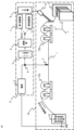
- FIG. 1 is a block diagram showing the configuration of a winding defect inspection device according to Embodiment 1;
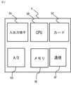
- FIG. 4 is a block diagram showing the structure of a storage unit in the winding defect inspection device according to Embodiment 1;
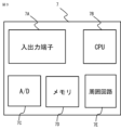
- FIG. 2 is a block diagram showing the structure of a calculator in the winding defect inspection device according to Embodiment 1;
- FIG. FIG. 4 is an enlarged view showing a discharge state in a defective portion of winding;
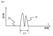
- FIG. 4 is a diagram showing the state of the current that flows when discharge occurs;
- 5 is a flowchart for explaining the operation of the winding defect inspection apparatus according to the first embodiment;
- FIG. 10 is a timing chart of accumulation by the accumulation unit and calculation by the arithmetic unit;
- FIG. 4 is a diagram showing the state of the current that flows when discharge occurs;
- Fig. 3 shows a simulation of test signals; It is a figure which shows the analysis result of a frequency characteristic.
- FIG. 4 is a perspective view showing a state in which a winding is wound around a member to be wound; 1 is a cross-sectional view showing an electric machine including a stator core, which is a wound member;
- FIG. 4 is a perspective view showing a state in which windings are wound around teeth of a stator core using a nozzle control unit;
- FIG. 9 is a block diagram showing the configuration of a winding defect inspection device according to Embodiment 2;
- FIG. 11 is a block diagram showing the configuration of a winding defect inspection device according to Embodiment 3;
- 10 is a flowchart for explaining the operation of the winding defect inspection device according to Embodiment 3;
- FIG. 12 is a block diagram showing the configuration of a winding defect inspection device according to Embodiment 4;
- FIG. 13 is a block diagram showing the configuration of a winding defect inspection device according to Embodiment 5;
- FIG. 13 is a block diagram showing the configuration of a winding defect inspection device according to Embodiment 6;
- 21A and 21B are diagrams showing changes in power supply voltage.
- FIG. 1 is a block diagram showing the configuration of a winding defect inspection apparatus according to Embodiment 1.
- the winding defect inspection apparatus according to the first embodiment includes a winding machine main body 14 for winding a winding 1 around a wound member 11 to manufacture a winding component of a rotating electric machine, and a defect detection unit 9 for the winding 1.
- the defect detection unit 9 includes a sensor 2, a power source 3, a discharge detection unit 5, an accumulation unit 6, and a plurality of N (N is a natural number of 2 or more) calculations from a first computing unit to an Nth computing unit. It is composed of a vessel 7.
- the individual computing units from the first computing unit to the N-th computing unit will be collectively referred to as the computing unit 7 .
- the sensor 2 is arranged in the middle of the path from one end 10 of the winding to the member 11 to be wound.
- Power supply 3 applies a voltage between sensor 2 and winding 1 .
- a discharge detector 5 detects a discharge current or charge amount 4 generated between the sensor 2 and the defective portion of the winding 1 due to a defect in the insulating layer of the winding 1 passing near the sensor 2 .
- the storage unit 6 receives the output from the discharge detection unit 5 and stores the detection signal. Accumulated detection signals are assigned to the plurality of calculators 7 .
- the winding machine main body 14 is composed of one winding end 10, tensioners 12a and 12b, a nozzle control section 13, and a member 11 to be wound.
- the tensioners 12a and 12b apply tension to the winding 1 from one end 10 of the winding to the member 11 to be wound, thereby suppressing the swinging of the winding 1.
- the nozzle control unit 13 is provided with a motor, and the nozzle 32 (see FIG. 12) is controlled by the motor in the x, y, and z directions shown in FIG.
- FIG. 2 is a block diagram showing the structure of the storage section 6.
- Components of the storage section 6 include an input/output terminal 6A, a CPU (Central Processing Unit) 6B, a card 6C, an A/D converter 6D, a memory 6E, a communication There is part 6F.
- an input/output terminal 6A receives an analog input signal, converts the analog signal into a digital signal by an A/D converter 6D, and stores the signal in a memory 6E or a card 6C. Then, the data stored in the computing unit 7 is passed through the communication unit 6F. These operations are managed by the CPU 6B.
- FIG. 3 is a block diagram showing the structure of the arithmetic unit 7.
- input/output terminal 7A receives an input signal and stores the signal in memory 7D. Then, the CPU 7B performs the calculation.
- the peripheral circuit 7E includes a signal communication circuit. Although the A/D converter 7C is not used in the operation described below, the A/D converter 7C is used as necessary.
- the defect detector 9 repeatedly accumulates and allocates detection signals and analyzes the frequency characteristics, accurately calculates the defect position of the running winding 1 in real time, and sends the calculation result to the host machine 8.
- the winding 1 is wound while changing its position in the x, y and z directions, and a motor is used to change the position in the x, y and z directions as described above.
- One role of the host device 8 is to issue commands to the motors in the x, y, and z directions.
- the internal structure of the host machine 8 is composed of various calculation units including a CPU.
- the host machine 8 outputs a warning based on the inspection results. Also, the host device 8 outputs an instruction signal to the nozzle control unit 13 to change the travel of the winding 1 .
- changing the travel corresponds to changing the winding position of the winding 1 .
- FIG. 12 which will be described later, a positional deflection command is issued from the host machine 8 so that defects do not adjoin each other, and each motor in charge of the x, y, and z directions receives this command. Based on this, the x, y, z position of the nozzle 32 (see FIG. 12) changes, and the winding position of the winding 1 changes. While the member 11 to be wrapped is fixed, the nozzle 32 is in a movable state.
- FIG. 4 is an enlarged view showing the state of discharge at the defective portion of the winding.
- the GND terminal of the power supply 3 is connected to one end of the winding 1 from which the insulating layer 16 is stripped, and the voltage output terminal of the power supply 3 and the sensor 2 are connected.
- the sensor 2 When an appropriate voltage is applied to the sensor 2, if the insulating layer 16 on the surface of the winding 1 has a defective portion 17 due to a scratch or a pinhole, etc., a gap between the core (copper wire) 15 of the winding 1 and the sensor 2 A discharge 18 is generated at , which causes a current to flow through the circuit comprising the power supply 3 , the sensor 2 and the winding 1 .
- FIG. 5 is a diagram showing the state of current flowing when discharge occurs.
- the inspection signals shown in FIG. Calculate the frequency of Therefore, it takes a long time to collect data and perform FFT conversion, and it is not possible to inspect defects in the winding 1 running at high speed in real time. For example, if the running speed of the winding 1 is 500 mm/s and the horizontal width of the sensor 2 (the width in the direction parallel to the running direction of the winding 1) is 10 mm, when inspecting the defective portion 17 of the winding 1, The FFT must be completed within 0.02s, which is difficult to achieve.
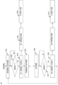
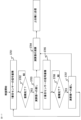
- FIG. 6 is a flowchart for explaining the operation of the winding defect inspection apparatus according to the first embodiment.
- a voltage is applied from the power source 3 to the sensor 2 to start the defect inspection of the winding 1 .
- the discharge detector 5 inspects the discharge between the sensor 2 and the winding 1.
- a discharge occurs between the sensor 2 and the winding 1, and a circulating circuit is formed by the power supply 3, the sensor 2 and the core 15 of the winding 1, and the discharge shown in FIG.
- a current 19 flows and is detected by the discharge detector 5 .
- the accumulation unit 6 continuously reads the output of the discharge detection unit 5 and accumulates the inspection signal.
- a data logger, an oscilloscope, a memory high coder, or the like is used as the storage section 6 .
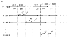
- FIG. 7 is a diagram showing a timing chart of accumulation by the accumulation unit 6 and calculation by the arithmetic unit 7.
- FIG. 6 When the storage unit 6 collects inspection signals for a certain time length (fixed time) ⁇ t1 (for example, 5 ms), it is determined that the storage is completed (YES) (step S602), and the first computing unit is the first computing unit. (step S603). If accumulation has not been completed (NO), accumulation continues.
- the first computing unit receives the inspection signal from the storage unit 6 over the receiving time 42, starts analyzing the frequency characteristics of the inspection signal, and performs the computation over the computing time 43 (step S604). At the same time, the accumulation unit 6 continues to accumulate the inspection signal over the same time length ⁇ t1 for the second time (step S605).
- the inspection signal is assigned to the second computing unit in the same manner as described above, and analysis of the inspection signal is started.
- the accumulation unit 6 Switch to assignment to the first calculator.
- the number N of the first to N-th calculators is determined by the accumulation time of the accumulator 6 and the calculation time of the calculator 7 .
- arithmetic unit 7 a plurality of microcontroller units (MCU), which are digital processors, may be used, or one or a plurality of field programmable gate arrays (FPGA) may be used.
- MCU microcontroller units
- FPGA field programmable gate arrays
- FIG. 8 is a simplified diagram for explaining the principle of determining the position of a winding defect, and is a perspective view showing a state in which a winding 1 is wound around a member 11 to be wound.
- the accumulation unit 6 accumulates a test signal with a time length of ⁇ t1 from the position O to the position P of the winding 1 .
- the signal from position O to position P shown in FIG. 9 is accumulated.
- the defect position Q is specified based on the traveling speed of the winding 1. In FIG. 9, if .DELTA.t2 is found, the defect position Q is specified based on the traveling speed of the winding 1. In FIG. 9,
- position O and position P have a positional relationship as shown in FIG. 8B.
- the inspection signals are passed from the storage unit 6 to any one of the first to N-th computing units, and the computation of the computing unit 7 that received the inspection signals starts.
- the sum of the receiving time 42 and the computing time 43 of the calculator 7 is assumed to be ⁇ t3. Assuming that the traveling speed of the winding 1 is constant and the distance from the sensor 2 to the position d of the member 11 to be wound is constant, the traveling time required for the winding 1 to reach the position d from the sensor 2 is determined. Let this be ⁇ t0.
- the position of the defect position Q between the position O and the position P can be specified, that is, if the time ⁇ t2 (time for specifying the defect position in the winding 1) shown in FIG. Since the speed is constant, the defect position Q can be identified while the winding 1 is running.
- the 1st to N-th calculators use the time when the test signal starts to be transferred each time as their own reference time 0. That is, as shown in FIG. 8B, the time at which the storage unit 6 completes the k-th storage and delivers the test signal to the k-th (1 ⁇ k ⁇ N) operator 7 among the first to N-th operators. be the reference time 0 of the k-th operator.
- ⁇ t2 be the detection time when a defect is detected by the k-th computing unit 7 of the first computing unit to the N-th computing unit.
- the time td at which the defect position Q reaches the position d of the wound member 11 can be calculated from the following equation (1).
- the 1st to Nth computing units communicate with the higher-level device 8 at the time calculated by their own calculation formula (1). For example, if there is no defect, the communication signal is set low. When a defect is detected, the communication signal is set high, and after communication, the communication signal is pulled back low.
- the time when the defective position Q reaches the position d of the wound member 11 is ⁇ t0-( ⁇ t1 ⁇ t2). In short, if ⁇ t2 is found, the running speed of the winding 1 is constant, so the time at which the defect position Q reaches the position d of the wound member 11 can be obtained from ⁇ t0.
- the time ⁇ t2 for specifying the defect position Q can be calculated.
- wavelet transform by Equation (2) shown below is used as an example of the method of analyzing the frequency characteristics of the test signal 19.
- Equation (2) f(x) is the test signal 19
- ⁇ (x, a, b) is the wavelet
- a and b are the wavelet parameters.
- W ⁇ (b, a) is the result of conversion, and the result of conversion includes the frequency components of the inspection signal 19 and the time of appearance of each frequency.
- FIG. 10 shows a simulation of the test signal.
- the simulated signal is not an actual detected signal but a signal created by a program based on an image of an actual signal.
- FIG. 11 shows the result of analyzing the frequency characteristics shown in FIG. 10 using equation (2).
- FIG. 10 shows a simulation of the test signal.
- the simulated signal is not an actual detected signal but a signal created by a program based on an image of an actual signal.
- FIG. 11 shows the result of analyzing the frequency characteristics shown in FIG. 10 using equation (2).
- the test signal shown in FIG. 9 is analyzed by equation (2). to have happened. That is, as in the case of the simulated signal shown in FIG. 11, in the actual inspection, if a frequency of around 20 MHz is detected, the winding 1 is determined to be defective.
- the frequency of the actually inspected signal may be 20 MHz, 100 MHz, or 15 kHz, and the generation timing of the defect signal can be calculated regardless of the frequency.
- ⁇ t2 is specified from the occurrence time of the frequency (for example, 20 MHz) (for example, ⁇ t2 is 2.5 ms in the case of FIGS. 10 and 11), and by using this ⁇ t2, the above equation (1) is obtained. As shown, the time td at which the defect reaches the position d of the member 11 to be wrapped can be calculated.
- FIG. 12 is a perspective view showing a state in which a winding is wound around a member to be wound.
- a defect 33a and a defect 33b are generated in the winding 1 so as to be adjacent to each other, and the winding 1 is wound as it is and assembled into a rotating electric machine as a component.
- a current is passed through the winding 1
- a discharge occurs between the defect 33a and the defect 33b, and the breakdown of the insulating layer between the defect 33a and the defect 33b spreads, possibly destroying the rotating electrical machine. .
- tk1 be the time when the first defect detection communication signal is sent from the first to N-th calculators
- tk2 be the time when the second communication is made.
- the host device 8 can issue a warning and change the running state of the winding 1.
- a defect in the winding 1 is detected for the third time (for example, when the third computing unit detects a defect after the first computing unit detects a defect)
- the first computation is performed in the same manner as described above.
- the distance 41 between the Nth defect and the first defect can be calculated by multiplying the diameter of the winding 1 by N.
- this distance 41 is an appropriate distance (a distance at which discharge does not occur)
- the host device 8 does not issue a warning. Also, when a defect is detected for the N+1 time, it is possible to determine whether the defects are adjacent by comparing with the detection time of the second defect.
- the thickness of the winding layer of the winding 1 wound around the member 11 to be wound should be taken into account.
- the thickness of the winding layer is 5 mm.
- the block diagram of FIG. 1 is just one example. That is, by arranging a plurality of defect detectors 9 including the sensor 2, the reliability of the defect inspection of the winding 1 can be improved. In this way, by repeatedly accumulating and allocating the inspection signals of the winding 1, even if the winding 1 runs at high speed, the defect position of the winding 1 can be determined continuously while ensuring high reliability. can do.
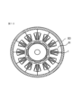
- FIG. 13 is a cross-sectional view showing an electric machine having a stator core, which is a member to be wound. It shows the state of being wound around the stator core.
- 14 is a perspective view showing a state in which the winding 1 is wound around the teeth of the stator core 81 using the nozzle control section 13.
- FIG. 13 a rotating electric machine is described as an example of the electric machine 80, but the electric machine 80 may be a linear motor.
- This electric machine 80 is equipped with a stator core 81 wound with a winding 1 that has been confirmed to have no insulation defects by using the winding defect inspection device described above.
- the electric machine 80 is manufactured, and the electric machine can be manufactured by including such a manufacturing step in the manufacturing method of the electric machine.
- the winding defect inspection apparatus of the present embodiment is applied to the winding process of the stator, which is the armature of a rotary electric machine or a linear motor, as an example of an electric machine. Therefore, according to the winding defect inspection apparatus according to the present embodiment, even if the winding 1 travels at high speed, the defective positions of the winding 1 are continuously detected in the entire winding 1 before winding. It can be confirmed with high reliability.
- a stator which is an armature of a rotary electric machine or direct-current machine, using the highly reliable winding 1 can be supplied.
- FIG. 15 is a block diagram showing the configuration of the winding defect inspection apparatus according to the second embodiment.
- the winding defect inspection apparatus according to the second embodiment has a sensor 2a above the winding 1 and a sensor 2b below the winding 1, and inspects for defects around the winding 1 with the sensors 2a and 2b.
- the operations of the winding defect inspection apparatus according to the present embodiment the operations of the discharge detection unit 5, the first to Nth computing units, and the host unit 8 are the same as those described in the first embodiment. be.
- the storage unit 6 simultaneously receives detection signals from the sensors 2a and 2b via the discharge detection unit 5, stores the two detection signals separately, and assigns data to the first to Nth computing units. .
- the inspection signal from the sensor 2a is allocated to the front half of the first computing unit to the Nth computing unit
- FIG. 15 is merely an example. That is, three or more sensors 2 can be arranged around the winding 1 at arbitrary angular intervals. Moreover, by arranging a plurality of defect detection units 9 including the sensors 2a and 2b, the reliability of the defect inspection of the winding 1 can be improved. In this way, by arranging a plurality of sensors 2 around the winding 1 and inspecting defects around the winding 1, even if the winding 1 runs at high speed, the defect position of the winding 1 can be detected continuously. moreover, it is possible to secure and determine higher reliability than in the case of the first embodiment.
- FIG. 16 is a block diagram showing the configuration of a winding defect inspection apparatus according to Embodiment 3. As shown in FIG. In FIG. 16, the same reference numerals as in FIG. 1 indicate the same or corresponding parts.
- the winding defect inspection apparatus according to the third embodiment has a sensor 2a and a sensor 2b arranged along the direction in which the winding 1 runs.
- the operations of the discharge detector 5, the calculator 7, and the host machine 8 are the same as those described in the first embodiment.
- FIG. 17 is a flow chart for explaining the operation of the winding defect inspection device according to the third embodiment.
- a voltage is applied from the power supply 3 to the sensor 2a (first sensor) and the sensor 2b (second sensor), and the defect inspection of the winding 1 is started.
- the discharge detection unit 5 inspects the discharge between the sensor 2a and the winding 1, and the storage unit 6 receives the output from the discharge detection unit 5. While reading (first inspection signal), the inspection signal is accumulated.
- the accumulation unit 6 collects data for a certain length of time (for example, 30 ms), it becomes "YES" in the accumulation completion step (step S702), and the accumulation signal is transferred to the calculator 7 (step S703).
- step S704 When the computing unit 7 receives the inspection signal from the storage unit 6, the computing unit 7 enters a computing step (step S704) and starts analyzing the frequency characteristics of the inspection signal. At the same time, the accumulation unit 6 continues to accumulate inspection signals (second inspection signals) of the same length of time (for example, 30 ms) from the sensor 2b (step S705). When the accumulation of the test signal from the sensor 2b is completed (step S706), the test signal is transferred to the calculator 7 (step S707), and the calculation step (step S704) by the calculator 7 is entered to analyze the frequency characteristics of the test signal. start. At the same time, the storage section 6 starts to store inspection signals from the sensor 2a again.
- second inspection signals inspection signals of the same length of time (for example, 30 ms) from the sensor 2b
- the arrangement distance L between the sensor 2a and the sensor 2b is determined by the running speed of the winding 1, the time required for receiving the inspection signal of the calculator 7, and the time required for calculation. Assuming that the traveling speed of the winding 1 is V, and the time required for receiving the inspection signal by the computing unit 7 and the time required for computation is T, the arrangement distance L is calculated by the following equation (4). Here, a margin may be added to the time T required for receiving the inspection signal by the calculator 7 and the calculation.
- FIG. 16 The configuration of FIG. 16 is merely an example. In other words, more than two sensors can be arranged along the running direction of the winding 1 . Further, by arranging a plurality of defect detection units 9 including the sensors 2a and 2b, the reliability of the defect inspection of the winding 1 can be improved. In this way, by arranging a plurality of sensors 2 along the running direction of the winding 1 and inspecting the winding 1 for defects, even if the winding 1 runs at high speed, the defect position of the winding 1 can be detected. It can be determined continuously and with higher reliability than in the case of the first embodiment.
- FIG. 18 is a block diagram showing the configuration of a winding defect inspection apparatus according to Embodiment 4.
- the winding defect inspection apparatus according to the fourth embodiment has a plurality of sensors 2a to 2d arranged above and below the winding 1, and inspects defects around the winding 1 with the plurality of sensors 2a to 2d. .
- the operations of the winding defect inspection apparatus according to this embodiment the operations of the discharge detector 5, the computing unit 7, and the host machine 8 are the same as those described in the third embodiment.
- the storage unit 6 receives the inspection signals from the sensors 2a to 2d simultaneously via the discharge detection unit 5, stores the inspection signals from the sensors 2a and 2b in one storage area, and stores the inspection signals from the sensors 2c and 2d. are stored in another storage area, stored separately and assigned to the first computing unit and the second computing unit.
- the inspection signals from the sensors 2a and 2b can be assigned to the first calculator, and the inspection signals from the sensors 2c and 2d can be assigned to the second calculator.
- FIG. 18 The configuration of FIG. 18 is merely an example. That is, three or more sensors 2 can be arranged around the winding 1 at arbitrary angular intervals. Moreover, by arranging a plurality of defect detection units 9 including the sensors 2a to 2d, the reliability of defect inspection of the winding 1 can be improved. In this way, by arranging a plurality of sensors 2a to 2d around the winding 1 and inspecting defects around the winding 1, even if the winding 1 runs at high speed, the defect position of the winding 1 can be detected. can be determined continuously with higher reliability than in the case of the first embodiment.
- FIG. 19 is a block diagram showing the configuration of a winding defect inspection apparatus according to Embodiment 5.
- the winding defect inspection apparatus according to Embodiment 5 has one sensor 2 above the winding 1 .
- One calculator 7 a is arranged as the calculator 7 .
- the operations of the discharge detection unit 5, the storage unit 6, and the host machine 8 are the same as those described in the first embodiment.
- the accumulation unit 6 receives the inspection signal from the sensor 2 via the discharge detection unit 5 and accumulates it in the accumulation area, and then transfers it to the calculator 7a.
- This embodiment can be applied when the running speed of the winding 1 is slow, for example, 50 mm/s.
- the time required for calculation in the calculator 7a is set to 30 ms, which is the same as in the first embodiment. Since the calculation of the calculator 7 is also completed by the time it is completed, defects in the winding 1 can be inspected.
- FIG. 19 The configuration of FIG. 19 is merely an example.
- a plurality of sensors 2 can be arranged around the winding 1 .
- the reliability of the defect inspection of the winding 1 can be improved. In this way, when the sensor 2 is arranged around the winding 1 and the winding 1 runs at a low speed, the defective position of the winding 1 can be determined continuously with high accuracy and high reliability. can be done.
- FIG. 20 is a block diagram showing the configuration of a winding defect inspection apparatus according to Embodiment 6.
- the winding defect inspection apparatus according to Embodiment 6 has a voltage detection unit 44 that detects the voltage of the power supply 3, and detects the discharge current between the sensor 2 and the winding 1 instead of detecting the discharge current between the sensor 2 and the winding 1.
- a defect in the winding 1 is inspected by detecting a change in the voltage of the power supply 3 when a discharge occurs between the windings 1, that is, a variation in the voltage applied between the sensor 2 and the winding 1.
- FIG. Among the operations of the winding defect inspection apparatus according to the present embodiment the operations of the discharge detection section 5, the calculator 7 and the host machine 8 are the same as those described in the first embodiment.
- FIG. 21A is a diagram showing changes in power supply voltage when there is no defect in the winding
- FIG. 21B is a diagram showing changes in power supply voltage when there is a defect in the winding.
- the voltage of the power supply 3 is detected by the resistors 45 and 46 of the voltage detection section 44 , noise processing is performed by the discharge detection section 5 , and the processed signal is passed to the accumulation section 6 .
- the frequency of the voltage signal between times t1 to t2 and t3 to t4 is high, for example, 10 MHz
- the defect voltage signal 48 is processed by the wavelet transform of (Equation 2) described in Embodiment 1
- a frequency of 10 MHz is also detected in addition to the frequency of 60 Hz, it can be determined that the winding 1 has a defect.
- a stator which is an armature of a rotary electric machine or direct-current machine, using the highly reliable winding 1 can be supplied.
Landscapes
- Engineering & Computer Science (AREA)
- Power Engineering (AREA)
- Manufacturing & Machinery (AREA)
- Physics & Mathematics (AREA)
- General Physics & Mathematics (AREA)
- Testing Of Short-Circuits, Discontinuities, Leakage, Or Incorrect Line Connections (AREA)
Priority Applications (1)
| Application Number | Priority Date | Filing Date | Title |
|---|---|---|---|
| JP2023555084A JP7668892B2 (ja) | 2021-10-13 | 2022-09-28 | 巻線欠陥検査装置、巻線欠陥検査装置を使用した電気機械の製造方法、及び巻線欠陥検査方法 |
Applications Claiming Priority (2)
| Application Number | Priority Date | Filing Date | Title |
|---|---|---|---|
| JP2021167870 | 2021-10-13 | ||
| JP2021-167870 | 2021-10-13 |
Publications (1)
| Publication Number | Publication Date |
|---|---|
| WO2023063078A1 true WO2023063078A1 (ja) | 2023-04-20 |
Family
ID=85988291
Family Applications (1)
| Application Number | Title | Priority Date | Filing Date |
|---|---|---|---|
| PCT/JP2022/036142 Ceased WO2023063078A1 (ja) | 2021-10-13 | 2022-09-28 | 巻線欠陥検査装置、巻線欠陥検査装置を使用した電気機械の製造方法、及び巻線欠陥検査方法 |
Country Status (2)
| Country | Link |
|---|---|
| JP (1) | JP7668892B2 (https=) |
| WO (1) | WO2023063078A1 (https=) |
Cited By (2)
| Publication number | Priority date | Publication date | Assignee | Title |
|---|---|---|---|---|
| WO2024203017A1 (ja) * | 2023-03-27 | 2024-10-03 | 三菱電機株式会社 | 巻線の欠陥検査装置 |
| WO2025074707A1 (ja) * | 2023-10-05 | 2025-04-10 | 三菱電機株式会社 | 巻線の欠陥検査装置、巻線の欠陥検査システムおよび巻線の欠陥検査方法 |
Citations (6)
| Publication number | Priority date | Publication date | Assignee | Title |
|---|---|---|---|---|
| JP2002131366A (ja) * | 2000-10-20 | 2002-05-09 | Toshiba Corp | 高電圧機器の内部部分放電監視装置 |
| JP2008042147A (ja) * | 2006-08-10 | 2008-02-21 | Hioki Ee Corp | 巻線機 |
| JP2014053340A (ja) * | 2012-09-05 | 2014-03-20 | Aisin Seiki Co Ltd | 欠陥自動補修巻線装置、および欠陥自動補修巻線方法 |
| JP2015062009A (ja) * | 2013-08-21 | 2015-04-02 | 学校法人 芝浦工業大学 | 部分放電試験用電源装置、部分放電試験方法及び部分放電試験機能付き巻線機 |
| US20150276880A1 (en) * | 2014-03-31 | 2015-10-01 | Eaton Corporation | System and method for detecting, localizing, and quantifying stator winding faults in ac motors |
| US20200343795A1 (en) * | 2017-11-06 | 2020-10-29 | Thyssenkrupp Ag | Device for producing stranded wires, a stranded wire and an electric machine having such a stranded wire |
-
2022
- 2022-09-28 JP JP2023555084A patent/JP7668892B2/ja active Active
- 2022-09-28 WO PCT/JP2022/036142 patent/WO2023063078A1/ja not_active Ceased
Patent Citations (6)
| Publication number | Priority date | Publication date | Assignee | Title |
|---|---|---|---|---|
| JP2002131366A (ja) * | 2000-10-20 | 2002-05-09 | Toshiba Corp | 高電圧機器の内部部分放電監視装置 |
| JP2008042147A (ja) * | 2006-08-10 | 2008-02-21 | Hioki Ee Corp | 巻線機 |
| JP2014053340A (ja) * | 2012-09-05 | 2014-03-20 | Aisin Seiki Co Ltd | 欠陥自動補修巻線装置、および欠陥自動補修巻線方法 |
| JP2015062009A (ja) * | 2013-08-21 | 2015-04-02 | 学校法人 芝浦工業大学 | 部分放電試験用電源装置、部分放電試験方法及び部分放電試験機能付き巻線機 |
| US20150276880A1 (en) * | 2014-03-31 | 2015-10-01 | Eaton Corporation | System and method for detecting, localizing, and quantifying stator winding faults in ac motors |
| US20200343795A1 (en) * | 2017-11-06 | 2020-10-29 | Thyssenkrupp Ag | Device for producing stranded wires, a stranded wire and an electric machine having such a stranded wire |
Cited By (2)
| Publication number | Priority date | Publication date | Assignee | Title |
|---|---|---|---|---|
| WO2024203017A1 (ja) * | 2023-03-27 | 2024-10-03 | 三菱電機株式会社 | 巻線の欠陥検査装置 |
| WO2025074707A1 (ja) * | 2023-10-05 | 2025-04-10 | 三菱電機株式会社 | 巻線の欠陥検査装置、巻線の欠陥検査システムおよび巻線の欠陥検査方法 |
Also Published As
| Publication number | Publication date |
|---|---|
| JPWO2023063078A1 (https=) | 2023-04-20 |
| JP7668892B2 (ja) | 2025-04-25 |
Similar Documents
| Publication | Publication Date | Title |
|---|---|---|
| WO2023063078A1 (ja) | 巻線欠陥検査装置、巻線欠陥検査装置を使用した電気機械の製造方法、及び巻線欠陥検査方法 | |
| JP5663318B2 (ja) | インバータ駆動回転電機の部分放電試験法 | |
| CN102135593A (zh) | 大电机绝缘状态在线诊断评估方法 | |
| CN110672644B (zh) | 电缆缓冲层状态评价方法及系统 | |
| Babel et al. | Condition-based monitoring and prognostic health management of electric machine stator winding insulation | |
| JP2019020278A (ja) | 回転機システムの診断装置、電力変換装置、回転機システム、および回転機システムの診断方法 | |
| JPWO2023063078A5 (https=) | ||
| Perisse et al. | Robust diagnostics of stator insulation based on high frequency resonances measurements | |
| US7616012B2 (en) | Systems, methods, and apparatus for measuring capacitance in a stator component | |
| JP2011242206A (ja) | 電力ケーブルの絶縁劣化診断方法及び絶縁劣化診断装置 | |
| KR101430040B1 (ko) | 절연검사장치 및 절연검사방법 | |
| WO2013160991A1 (ja) | シンチレーション推定方法 | |
| CN112243499B (zh) | 用于测量电驱动系统中的局部放电的方法 | |
| KR20130092462A (ko) | 부품내장기판의 검사방법 | |
| JPH10177053A (ja) | 回転電機の固定子コイルの劣化検知方法及び装置 | |
| JP7374348B2 (ja) | 被覆欠陥検出装置と被覆欠陥検出方法、および回転電機の製造方法 | |
| Grubelnik et al. | Un-impregnated vpi tape testing and effects on dielectric performance of VPI insulation systems | |
| JP2975039B2 (ja) | モータ用巻線コイルの巻装異常検出装置 | |
| JP2017015624A (ja) | 絶縁劣化測定方法及び絶縁劣化測定装置 | |
| Toudji et al. | Predictive diagnostic based on HF modeling of electrical machines windings | |
| RU2668996C1 (ru) | Способ диагностирования состояния коммутации коллекторных электрических машин | |
| KR102099070B1 (ko) | 발전기 고정자 권선의 흡습 분석 장치 및 방법 | |
| JP7107755B2 (ja) | コイル導線の相間絶縁検査方法 | |
| US12265127B2 (en) | Method of detecting and positioning insulation failure of aircraft generator | |
| JP2007274870A (ja) | ワニス含浸状態判定方法及び装置、並びに電機子の製造方法 |
Legal Events
| Date | Code | Title | Description |
|---|---|---|---|
| 121 | Ep: the epo has been informed by wipo that ep was designated in this application |
Ref document number: 22880774 Country of ref document: EP Kind code of ref document: A1 |
|
| WWE | Wipo information: entry into national phase |
Ref document number: 2023555084 Country of ref document: JP |
|
| NENP | Non-entry into the national phase |
Ref country code: DE |
|
| 122 | Ep: pct application non-entry in european phase |
Ref document number: 22880774 Country of ref document: EP Kind code of ref document: A1 |