WO2023062963A1 - Laminate, packaging material, and packaged article - Google Patents
Laminate, packaging material, and packaged article Download PDFInfo
- Publication number
- WO2023062963A1 WO2023062963A1 PCT/JP2022/033186 JP2022033186W WO2023062963A1 WO 2023062963 A1 WO2023062963 A1 WO 2023062963A1 JP 2022033186 W JP2022033186 W JP 2022033186W WO 2023062963 A1 WO2023062963 A1 WO 2023062963A1
- Authority
- WO
- WIPO (PCT)
- Prior art keywords
- layer
- laminate
- birefringence
- film
- polyethylene
- Prior art date
Links
- 239000005022 packaging material Substances 0.000 title description 17
- 239000010410 layer Substances 0.000 claims abstract description 645
- -1 polyethylene Polymers 0.000 claims abstract description 129
- 238000000034 method Methods 0.000 claims abstract description 108
- 239000004698 Polyethylene Substances 0.000 claims abstract description 103
- 229920000573 polyethylene Polymers 0.000 claims abstract description 103
- 239000000565 sealant Substances 0.000 claims abstract description 88
- 239000012790 adhesive layer Substances 0.000 claims abstract description 73
- 239000000463 material Substances 0.000 claims description 114
- 230000004888 barrier function Effects 0.000 claims description 85
- 239000011241 protective layer Substances 0.000 claims description 84
- 239000000758 substrate Substances 0.000 claims description 59
- 229920005989 resin Polymers 0.000 claims description 49
- 239000011347 resin Substances 0.000 claims description 49
- 229920001187 thermosetting polymer Polymers 0.000 claims description 8
- 239000010408 film Substances 0.000 description 196
- 239000002585 base Substances 0.000 description 138
- 239000007789 gas Substances 0.000 description 83
- 239000000853 adhesive Substances 0.000 description 68
- 230000001070 adhesive effect Effects 0.000 description 68
- 238000011156 evaluation Methods 0.000 description 45
- 239000011248 coating agent Substances 0.000 description 43
- 238000000576 coating method Methods 0.000 description 43
- 239000000243 solution Substances 0.000 description 41
- 150000002484 inorganic compounds Chemical class 0.000 description 39
- 229910010272 inorganic material Inorganic materials 0.000 description 39
- 238000005259 measurement Methods 0.000 description 38
- OKKJLVBELUTLKV-UHFFFAOYSA-N Methanol Chemical compound OC OKKJLVBELUTLKV-UHFFFAOYSA-N 0.000 description 36
- 239000007788 liquid Substances 0.000 description 34
- 238000007789 sealing Methods 0.000 description 34
- 239000011247 coating layer Substances 0.000 description 32
- 229920005862 polyol Polymers 0.000 description 26
- JOYRKODLDBILNP-UHFFFAOYSA-N Ethyl urethane Chemical compound CCOC(N)=O JOYRKODLDBILNP-UHFFFAOYSA-N 0.000 description 25
- KFZMGEQAYNKOFK-UHFFFAOYSA-N isopropyl alcohol Natural products CC(C)O KFZMGEQAYNKOFK-UHFFFAOYSA-N 0.000 description 25
- XEKOWRVHYACXOJ-UHFFFAOYSA-N Ethyl acetate Chemical compound CCOC(C)=O XEKOWRVHYACXOJ-UHFFFAOYSA-N 0.000 description 24
- XLYOFNOQVPJJNP-UHFFFAOYSA-N water Chemical compound O XLYOFNOQVPJJNP-UHFFFAOYSA-N 0.000 description 24
- 238000002441 X-ray diffraction Methods 0.000 description 20
- 230000000052 comparative effect Effects 0.000 description 19
- DVKJHBMWWAPEIU-UHFFFAOYSA-N toluene 2,4-diisocyanate Chemical compound CC1=CC=C(N=C=O)C=C1N=C=O DVKJHBMWWAPEIU-UHFFFAOYSA-N 0.000 description 18
- 238000003851 corona treatment Methods 0.000 description 17
- 238000004519 manufacturing process Methods 0.000 description 17
- 238000002360 preparation method Methods 0.000 description 17
- VYPSYNLAJGMNEJ-UHFFFAOYSA-N Silicium dioxide Chemical compound O=[Si]=O VYPSYNLAJGMNEJ-UHFFFAOYSA-N 0.000 description 15
- 229910052814 silicon oxide Inorganic materials 0.000 description 15
- 239000007787 solid Substances 0.000 description 15
- 239000000976 ink Substances 0.000 description 14
- 238000004806 packaging method and process Methods 0.000 description 14
- 238000011282 treatment Methods 0.000 description 14
- 229920001903 high density polyethylene Polymers 0.000 description 13
- 239000004700 high-density polyethylene Substances 0.000 description 13
- 239000000126 substance Substances 0.000 description 13
- QVGXLLKOCUKJST-UHFFFAOYSA-N atomic oxygen Chemical compound [O] QVGXLLKOCUKJST-UHFFFAOYSA-N 0.000 description 12
- 229920001179 medium density polyethylene Polymers 0.000 description 12
- 239000004701 medium-density polyethylene Substances 0.000 description 12
- 238000002156 mixing Methods 0.000 description 12
- 239000000203 mixture Substances 0.000 description 12
- 239000001301 oxygen Substances 0.000 description 12
- 229910052760 oxygen Inorganic materials 0.000 description 12
- 238000007639 printing Methods 0.000 description 12
- 238000007756 gravure coating Methods 0.000 description 11
- 239000006087 Silane Coupling Agent Substances 0.000 description 10
- 230000015572 biosynthetic process Effects 0.000 description 10
- 230000007062 hydrolysis Effects 0.000 description 10
- 238000006460 hydrolysis reaction Methods 0.000 description 10
- 239000000178 monomer Substances 0.000 description 10
- TWNQGVIAIRXVLR-UHFFFAOYSA-N oxo(oxoalumanyloxy)alumane Chemical compound O=[Al]O[Al]=O TWNQGVIAIRXVLR-UHFFFAOYSA-N 0.000 description 10
- 239000004962 Polyamide-imide Substances 0.000 description 9
- YXFVVABEGXRONW-UHFFFAOYSA-N Toluene Chemical compound CC1=CC=CC=C1 YXFVVABEGXRONW-UHFFFAOYSA-N 0.000 description 9
- 125000002887 hydroxy group Chemical group [H]O* 0.000 description 9
- 229920000092 linear low density polyethylene Polymers 0.000 description 9
- 239000004707 linear low-density polyethylene Substances 0.000 description 9
- 238000002844 melting Methods 0.000 description 9
- 230000008018 melting Effects 0.000 description 9
- 239000011259 mixed solution Substances 0.000 description 9
- 229920002312 polyamide-imide Polymers 0.000 description 9
- 238000012360 testing method Methods 0.000 description 9
- 239000000654 additive Substances 0.000 description 8
- 230000000694 effects Effects 0.000 description 8
- 229910052751 metal Inorganic materials 0.000 description 8
- 239000002184 metal Substances 0.000 description 8
- 238000009832 plasma treatment Methods 0.000 description 8
- 239000000047 product Substances 0.000 description 8
- 239000004372 Polyvinyl alcohol Substances 0.000 description 7
- 238000005520 cutting process Methods 0.000 description 7
- 229920001684 low density polyethylene Polymers 0.000 description 7
- 239000004702 low-density polyethylene Substances 0.000 description 7
- 230000004048 modification Effects 0.000 description 7
- 238000012986 modification Methods 0.000 description 7
- 230000002093 peripheral effect Effects 0.000 description 7
- 229920000768 polyamine Polymers 0.000 description 7
- 150000003077 polyols Chemical class 0.000 description 7
- 229920002451 polyvinyl alcohol Polymers 0.000 description 7
- 239000002904 solvent Substances 0.000 description 7
- 238000001771 vacuum deposition Methods 0.000 description 7
- LFQSCWFLJHTTHZ-UHFFFAOYSA-N Ethanol Chemical compound CCO LFQSCWFLJHTTHZ-UHFFFAOYSA-N 0.000 description 6
- 229920010126 Linear Low Density Polyethylene (LLDPE) Polymers 0.000 description 6
- 239000003795 chemical substances by application Substances 0.000 description 6
- 238000010586 diagram Methods 0.000 description 6
- 238000010438 heat treatment Methods 0.000 description 6
- 239000012948 isocyanate Substances 0.000 description 6
- 229920000620 organic polymer Polymers 0.000 description 6
- 229920000642 polymer Polymers 0.000 description 6
- 229920005749 polyurethane resin Polymers 0.000 description 6
- 238000012545 processing Methods 0.000 description 6
- RTTZISZSHSCFRH-UHFFFAOYSA-N 1,3-bis(isocyanatomethyl)benzene Chemical compound O=C=NCC1=CC=CC(CN=C=O)=C1 RTTZISZSHSCFRH-UHFFFAOYSA-N 0.000 description 5
- IJGRMHOSHXDMSA-UHFFFAOYSA-N Atomic nitrogen Chemical compound N#N IJGRMHOSHXDMSA-UHFFFAOYSA-N 0.000 description 5
- 239000002028 Biomass Substances 0.000 description 5
- VGGSQFUCUMXWEO-UHFFFAOYSA-N Ethene Chemical compound C=C VGGSQFUCUMXWEO-UHFFFAOYSA-N 0.000 description 5
- 239000005977 Ethylene Substances 0.000 description 5
- 229910004298 SiO 2 Inorganic materials 0.000 description 5
- 150000004703 alkoxides Chemical class 0.000 description 5
- 230000005540 biological transmission Effects 0.000 description 5
- 238000001035 drying Methods 0.000 description 5
- 238000010894 electron beam technology Methods 0.000 description 5
- 125000001449 isopropyl group Chemical group [H]C([H])([H])C([H])(*)C([H])([H])[H] 0.000 description 5
- 229920013716 polyethylene resin Polymers 0.000 description 5
- OCKGFTQIICXDQW-ZEQRLZLVSA-N 5-[(1r)-1-hydroxy-2-[4-[(2r)-2-hydroxy-2-(4-methyl-1-oxo-3h-2-benzofuran-5-yl)ethyl]piperazin-1-yl]ethyl]-4-methyl-3h-2-benzofuran-1-one Chemical compound C1=C2C(=O)OCC2=C(C)C([C@@H](O)CN2CCN(CC2)C[C@H](O)C2=CC=C3C(=O)OCC3=C2C)=C1 OCKGFTQIICXDQW-ZEQRLZLVSA-N 0.000 description 4
- 150000001252 acrylic acid derivatives Chemical class 0.000 description 4
- 239000007795 chemical reaction product Substances 0.000 description 4
- 229920001577 copolymer Polymers 0.000 description 4
- 239000013078 crystal Substances 0.000 description 4
- 238000009820 dry lamination Methods 0.000 description 4
- 238000003475 lamination Methods 0.000 description 4
- 229910044991 metal oxide Inorganic materials 0.000 description 4
- 150000004706 metal oxides Chemical class 0.000 description 4
- 239000003960 organic solvent Substances 0.000 description 4
- 230000035699 permeability Effects 0.000 description 4
- 229920000728 polyester Polymers 0.000 description 4
- 238000004064 recycling Methods 0.000 description 4
- 238000004381 surface treatment Methods 0.000 description 4
- PZJJKWKADRNWSW-UHFFFAOYSA-N trimethoxysilicon Chemical compound CO[Si](OC)OC PZJJKWKADRNWSW-UHFFFAOYSA-N 0.000 description 4
- 238000007740 vapor deposition Methods 0.000 description 4
- 230000037303 wrinkles Effects 0.000 description 4
- 239000004925 Acrylic resin Substances 0.000 description 3
- 101100453790 Drosophila melanogaster Kebab gene Proteins 0.000 description 3
- 239000007983 Tris buffer Substances 0.000 description 3
- 238000010790 dilution Methods 0.000 description 3
- 239000012895 dilution Substances 0.000 description 3
- 208000028659 discharge Diseases 0.000 description 3
- 238000000313 electron-beam-induced deposition Methods 0.000 description 3
- 235000013305 food Nutrition 0.000 description 3
- 238000007646 gravure printing Methods 0.000 description 3
- ZFSLODLOARCGLH-UHFFFAOYSA-N isocyanuric acid Chemical compound OC1=NC(O)=NC(O)=N1 ZFSLODLOARCGLH-UHFFFAOYSA-N 0.000 description 3
- 235000015231 kebab Nutrition 0.000 description 3
- 150000002902 organometallic compounds Chemical class 0.000 description 3
- 238000005268 plasma chemical vapour deposition Methods 0.000 description 3
- 229920006122 polyamide resin Polymers 0.000 description 3
- 239000004711 α-olefin Substances 0.000 description 3
- VXNZUUAINFGPBY-UHFFFAOYSA-N 1-Butene Chemical compound CCC=C VXNZUUAINFGPBY-UHFFFAOYSA-N 0.000 description 2
- AFFLGGQVNFXPEV-UHFFFAOYSA-N 1-decene Chemical compound CCCCCCCCC=C AFFLGGQVNFXPEV-UHFFFAOYSA-N 0.000 description 2
- CRSBERNSMYQZNG-UHFFFAOYSA-N 1-dodecene Chemical compound CCCCCCCCCCC=C CRSBERNSMYQZNG-UHFFFAOYSA-N 0.000 description 2
- GQEZCXVZFLOKMC-UHFFFAOYSA-N 1-hexadecene Chemical compound CCCCCCCCCCCCCCC=C GQEZCXVZFLOKMC-UHFFFAOYSA-N 0.000 description 2
- LIKMAJRDDDTEIG-UHFFFAOYSA-N 1-hexene Chemical compound CCCCC=C LIKMAJRDDDTEIG-UHFFFAOYSA-N 0.000 description 2
- KWKAKUADMBZCLK-UHFFFAOYSA-N 1-octene Chemical compound CCCCCCC=C KWKAKUADMBZCLK-UHFFFAOYSA-N 0.000 description 2
- HFDVRLIODXPAHB-UHFFFAOYSA-N 1-tetradecene Chemical compound CCCCCCCCCCCCC=C HFDVRLIODXPAHB-UHFFFAOYSA-N 0.000 description 2
- UPMLOUAZCHDJJD-UHFFFAOYSA-N 4,4'-Diphenylmethane Diisocyanate Chemical compound C1=CC(N=C=O)=CC=C1CC1=CC=C(N=C=O)C=C1 UPMLOUAZCHDJJD-UHFFFAOYSA-N 0.000 description 2
- WSSSPWUEQFSQQG-UHFFFAOYSA-N 4-methyl-1-pentene Chemical compound CC(C)CC=C WSSSPWUEQFSQQG-UHFFFAOYSA-N 0.000 description 2
- DFVOXRAAHOJJBN-UHFFFAOYSA-N 6-methylhept-1-ene Chemical compound CC(C)CCCC=C DFVOXRAAHOJJBN-UHFFFAOYSA-N 0.000 description 2
- 229920000178 Acrylic resin Polymers 0.000 description 2
- QGZKDVFQNNGYKY-UHFFFAOYSA-N Ammonia Chemical compound N QGZKDVFQNNGYKY-UHFFFAOYSA-N 0.000 description 2
- XKRFYHLGVUSROY-UHFFFAOYSA-N Argon Chemical compound [Ar] XKRFYHLGVUSROY-UHFFFAOYSA-N 0.000 description 2
- MYMOFIZGZYHOMD-UHFFFAOYSA-N Dioxygen Chemical compound O=O MYMOFIZGZYHOMD-UHFFFAOYSA-N 0.000 description 2
- 229920000219 Ethylene vinyl alcohol Polymers 0.000 description 2
- 239000005057 Hexamethylene diisocyanate Substances 0.000 description 2
- CBENFWSGALASAD-UHFFFAOYSA-N Ozone Chemical compound [O-][O+]=O CBENFWSGALASAD-UHFFFAOYSA-N 0.000 description 2
- ISWSIDIOOBJBQZ-UHFFFAOYSA-N Phenol Chemical compound OC1=CC=CC=C1 ISWSIDIOOBJBQZ-UHFFFAOYSA-N 0.000 description 2
- 239000004721 Polyphenylene oxide Substances 0.000 description 2
- PPBRXRYQALVLMV-UHFFFAOYSA-N Styrene Chemical compound C=CC1=CC=CC=C1 PPBRXRYQALVLMV-UHFFFAOYSA-N 0.000 description 2
- 229920010346 Very Low Density Polyethylene (VLDPE) Polymers 0.000 description 2
- 229910052782 aluminium Inorganic materials 0.000 description 2
- XAGFODPZIPBFFR-UHFFFAOYSA-N aluminium Chemical compound [Al] XAGFODPZIPBFFR-UHFFFAOYSA-N 0.000 description 2
- 239000003963 antioxidant agent Substances 0.000 description 2
- 238000006243 chemical reaction Methods 0.000 description 2
- 238000005229 chemical vapour deposition Methods 0.000 description 2
- 150000001875 compounds Chemical class 0.000 description 2
- 239000003431 cross linking reagent Substances 0.000 description 2
- 238000013461 design Methods 0.000 description 2
- 230000006866 deterioration Effects 0.000 description 2
- 229910001873 dinitrogen Inorganic materials 0.000 description 2
- 229910001882 dioxygen Inorganic materials 0.000 description 2
- 238000009826 distribution Methods 0.000 description 2
- 229920001971 elastomer Polymers 0.000 description 2
- 229920006332 epoxy adhesive Polymers 0.000 description 2
- 238000001125 extrusion Methods 0.000 description 2
- 125000001475 halogen functional group Chemical group 0.000 description 2
- UQEAIHBTYFGYIE-UHFFFAOYSA-N hexamethyldisiloxane Chemical compound C[Si](C)(C)O[Si](C)(C)C UQEAIHBTYFGYIE-UHFFFAOYSA-N 0.000 description 2
- RRAMGCGOFNQTLD-UHFFFAOYSA-N hexamethylene diisocyanate Chemical compound O=C=NCCCCCCN=C=O RRAMGCGOFNQTLD-UHFFFAOYSA-N 0.000 description 2
- 238000007759 kiss coating Methods 0.000 description 2
- 239000002346 layers by function Substances 0.000 description 2
- CPLXHLVBOLITMK-UHFFFAOYSA-N magnesium oxide Inorganic materials [Mg]=O CPLXHLVBOLITMK-UHFFFAOYSA-N 0.000 description 2
- 239000000395 magnesium oxide Substances 0.000 description 2
- AXZKOIWUVFPNLO-UHFFFAOYSA-N magnesium;oxygen(2-) Chemical compound [O-2].[Mg+2] AXZKOIWUVFPNLO-UHFFFAOYSA-N 0.000 description 2
- 238000000691 measurement method Methods 0.000 description 2
- IBIKHMZPHNKTHM-RDTXWAMCSA-N merck compound 25 Chemical compound C1C[C@@H](C(O)=O)[C@H](O)CN1C(C1=C(F)C=CC=C11)=NN1C(=O)C1=C(Cl)C=CC=C1C1CC1 IBIKHMZPHNKTHM-RDTXWAMCSA-N 0.000 description 2
- 238000001465 metallisation Methods 0.000 description 2
- VAMFXQBUQXONLZ-UHFFFAOYSA-N n-alpha-eicosene Natural products CCCCCCCCCCCCCCCCCCC=C VAMFXQBUQXONLZ-UHFFFAOYSA-N 0.000 description 2
- CCCMONHAUSKTEQ-UHFFFAOYSA-N octadec-1-ene Chemical compound CCCCCCCCCCCCCCCCC=C CCCMONHAUSKTEQ-UHFFFAOYSA-N 0.000 description 2
- 238000007645 offset printing Methods 0.000 description 2
- 230000003647 oxidation Effects 0.000 description 2
- 238000007254 oxidation reaction Methods 0.000 description 2
- 229920006280 packaging film Polymers 0.000 description 2
- 239000012785 packaging film Substances 0.000 description 2
- YWAKXRMUMFPDSH-UHFFFAOYSA-N pentene Chemical compound CCCC=C YWAKXRMUMFPDSH-UHFFFAOYSA-N 0.000 description 2
- 238000005240 physical vapour deposition Methods 0.000 description 2
- 239000000049 pigment Substances 0.000 description 2
- 239000002985 plastic film Substances 0.000 description 2
- 229920006255 plastic film Polymers 0.000 description 2
- 229920001225 polyester resin Polymers 0.000 description 2
- 239000004645 polyester resin Substances 0.000 description 2
- 229920000570 polyether Polymers 0.000 description 2
- 229920002635 polyurethane Polymers 0.000 description 2
- 239000004814 polyurethane Substances 0.000 description 2
- 230000008569 process Effects 0.000 description 2
- 238000007763 reverse roll coating Methods 0.000 description 2
- 102220012437 rs397516085 Human genes 0.000 description 2
- 239000005060 rubber Substances 0.000 description 2
- 238000007650 screen-printing Methods 0.000 description 2
- 239000013464 silicone adhesive Substances 0.000 description 2
- 230000035882 stress Effects 0.000 description 2
- 230000003685 thermal hair damage Effects 0.000 description 2
- 239000010409 thin film Substances 0.000 description 2
- 238000012546 transfer Methods 0.000 description 2
- 229920002554 vinyl polymer Polymers 0.000 description 2
- 229920003169 water-soluble polymer Polymers 0.000 description 2
- 229920002818 (Hydroxyethyl)methacrylate Polymers 0.000 description 1
- 229940106006 1-eicosene Drugs 0.000 description 1
- FIKTURVKRGQNQD-UHFFFAOYSA-N 1-eicosene Natural products CCCCCCCCCCCCCCCCCC=CC(O)=O FIKTURVKRGQNQD-UHFFFAOYSA-N 0.000 description 1
- IEVADDDOVGMCSI-UHFFFAOYSA-N 2-hydroxybutyl 2-methylprop-2-enoate Chemical compound CCC(O)COC(=O)C(C)=C IEVADDDOVGMCSI-UHFFFAOYSA-N 0.000 description 1
- LZMNXXQIQIHFGC-UHFFFAOYSA-N 3-[dimethoxy(methyl)silyl]propyl 2-methylprop-2-enoate Chemical compound CO[Si](C)(OC)CCCOC(=O)C(C)=C LZMNXXQIQIHFGC-UHFFFAOYSA-N 0.000 description 1
- OXYZDRAJMHGSMW-UHFFFAOYSA-N 3-chloropropyl(trimethoxy)silane Chemical compound CO[Si](OC)(OC)CCCCl OXYZDRAJMHGSMW-UHFFFAOYSA-N 0.000 description 1
- KNTKCYKJRSMRMZ-UHFFFAOYSA-N 3-chloropropyl-dimethoxy-methylsilane Chemical compound CO[Si](C)(OC)CCCCl KNTKCYKJRSMRMZ-UHFFFAOYSA-N 0.000 description 1
- GNSFRPWPOGYVLO-UHFFFAOYSA-N 3-hydroxypropyl 2-methylprop-2-enoate Chemical compound CC(=C)C(=O)OCCCO GNSFRPWPOGYVLO-UHFFFAOYSA-N 0.000 description 1
- YHQXBTXEYZIYOV-UHFFFAOYSA-N 3-methylbut-1-ene Chemical compound CC(C)C=C YHQXBTXEYZIYOV-UHFFFAOYSA-N 0.000 description 1
- XDLMVUHYZWKMMD-UHFFFAOYSA-N 3-trimethoxysilylpropyl 2-methylprop-2-enoate Chemical compound CO[Si](OC)(OC)CCCOC(=O)C(C)=C XDLMVUHYZWKMMD-UHFFFAOYSA-N 0.000 description 1
- OKTJSMMVPCPJKN-UHFFFAOYSA-N Carbon Chemical compound [C] OKTJSMMVPCPJKN-UHFFFAOYSA-N 0.000 description 1
- 229920002134 Carboxymethyl cellulose Polymers 0.000 description 1
- 239000004593 Epoxy Substances 0.000 description 1
- 239000004606 Fillers/Extenders Substances 0.000 description 1
- WOBHKFSMXKNTIM-UHFFFAOYSA-N Hydroxyethyl methacrylate Chemical compound CC(=C)C(=O)OCCO WOBHKFSMXKNTIM-UHFFFAOYSA-N 0.000 description 1
- 229920000877 Melamine resin Polymers 0.000 description 1
- 239000000020 Nitrocellulose Substances 0.000 description 1
- 239000004793 Polystyrene Substances 0.000 description 1
- 241000238370 Sepia Species 0.000 description 1
- 229910052581 Si3N4 Inorganic materials 0.000 description 1
- 229910004205 SiNX Inorganic materials 0.000 description 1
- BLRPTPMANUNPDV-UHFFFAOYSA-N Silane Chemical compound [SiH4] BLRPTPMANUNPDV-UHFFFAOYSA-N 0.000 description 1
- BQCADISMDOOEFD-UHFFFAOYSA-N Silver Chemical compound [Ag] BQCADISMDOOEFD-UHFFFAOYSA-N 0.000 description 1
- 229920002472 Starch Polymers 0.000 description 1
- NINIDFKCEFEMDL-UHFFFAOYSA-N Sulfur Chemical compound [S] NINIDFKCEFEMDL-UHFFFAOYSA-N 0.000 description 1
- BOTDANWDWHJENH-UHFFFAOYSA-N Tetraethyl orthosilicate Chemical compound CCO[Si](OCC)(OCC)OCC BOTDANWDWHJENH-UHFFFAOYSA-N 0.000 description 1
- RTAQQCXQSZGOHL-UHFFFAOYSA-N Titanium Chemical compound [Ti] RTAQQCXQSZGOHL-UHFFFAOYSA-N 0.000 description 1
- 239000004708 Very-low-density polyethylene Substances 0.000 description 1
- XTXRWKRVRITETP-UHFFFAOYSA-N Vinyl acetate Chemical compound CC(=O)OC=C XTXRWKRVRITETP-UHFFFAOYSA-N 0.000 description 1
- BZHJMEDXRYGGRV-UHFFFAOYSA-N Vinyl chloride Chemical compound ClC=C BZHJMEDXRYGGRV-UHFFFAOYSA-N 0.000 description 1
- FJWGYAHXMCUOOM-QHOUIDNNSA-N [(2s,3r,4s,5r,6r)-2-[(2r,3r,4s,5r,6s)-4,5-dinitrooxy-2-(nitrooxymethyl)-6-[(2r,3r,4s,5r,6s)-4,5,6-trinitrooxy-2-(nitrooxymethyl)oxan-3-yl]oxyoxan-3-yl]oxy-3,5-dinitrooxy-6-(nitrooxymethyl)oxan-4-yl] nitrate Chemical compound O([C@@H]1O[C@@H]([C@H]([C@H](O[N+]([O-])=O)[C@H]1O[N+]([O-])=O)O[C@H]1[C@@H]([C@@H](O[N+]([O-])=O)[C@H](O[N+]([O-])=O)[C@@H](CO[N+]([O-])=O)O1)O[N+]([O-])=O)CO[N+](=O)[O-])[C@@H]1[C@@H](CO[N+]([O-])=O)O[C@@H](O[N+]([O-])=O)[C@H](O[N+]([O-])=O)[C@H]1O[N+]([O-])=O FJWGYAHXMCUOOM-QHOUIDNNSA-N 0.000 description 1
- 239000006096 absorbing agent Substances 0.000 description 1
- 150000001241 acetals Chemical class 0.000 description 1
- 125000005396 acrylic acid ester group Chemical group 0.000 description 1
- NIXOWILDQLNWCW-UHFFFAOYSA-N acrylic acid group Chemical group C(C=C)(=O)O NIXOWILDQLNWCW-UHFFFAOYSA-N 0.000 description 1
- 230000032683 aging Effects 0.000 description 1
- 239000003513 alkali Substances 0.000 description 1
- 150000001336 alkenes Chemical class 0.000 description 1
- SMZOGRDCAXLAAR-UHFFFAOYSA-N aluminium isopropoxide Chemical compound [Al+3].CC(C)[O-].CC(C)[O-].CC(C)[O-] SMZOGRDCAXLAAR-UHFFFAOYSA-N 0.000 description 1
- 229910021529 ammonia Inorganic materials 0.000 description 1
- 239000002216 antistatic agent Substances 0.000 description 1
- 239000007864 aqueous solution Substances 0.000 description 1
- 229910052786 argon Inorganic materials 0.000 description 1
- 125000003118 aryl group Chemical group 0.000 description 1
- 239000012298 atmosphere Substances 0.000 description 1
- 238000005452 bending Methods 0.000 description 1
- 239000011230 binding agent Substances 0.000 description 1
- 239000002981 blocking agent Substances 0.000 description 1
- 230000000903 blocking effect Effects 0.000 description 1
- QHIWVLPBUQWDMQ-UHFFFAOYSA-N butyl prop-2-enoate;methyl 2-methylprop-2-enoate;prop-2-enoic acid Chemical compound OC(=O)C=C.COC(=O)C(C)=C.CCCCOC(=O)C=C QHIWVLPBUQWDMQ-UHFFFAOYSA-N 0.000 description 1
- 229910052799 carbon Inorganic materials 0.000 description 1
- 125000004432 carbon atom Chemical group C* 0.000 description 1
- 239000001768 carboxy methyl cellulose Substances 0.000 description 1
- 235000010948 carboxy methyl cellulose Nutrition 0.000 description 1
- 150000001732 carboxylic acid derivatives Chemical class 0.000 description 1
- 239000008112 carboxymethyl-cellulose Substances 0.000 description 1
- 239000003054 catalyst Substances 0.000 description 1
- 230000008859 change Effects 0.000 description 1
- 238000004140 cleaning Methods 0.000 description 1
- 239000002131 composite material Substances 0.000 description 1
- 239000000356 contaminant Substances 0.000 description 1
- 238000004132 cross linking Methods 0.000 description 1
- 230000006378 damage Effects 0.000 description 1
- 230000007547 defect Effects 0.000 description 1
- 239000002274 desiccant Substances 0.000 description 1
- 229940069096 dodecene Drugs 0.000 description 1
- 239000003814 drug Substances 0.000 description 1
- BXKDSDJJOVIHMX-UHFFFAOYSA-N edrophonium chloride Chemical compound [Cl-].CC[N+](C)(C)C1=CC=CC(O)=C1 BXKDSDJJOVIHMX-UHFFFAOYSA-N 0.000 description 1
- 238000005566 electron beam evaporation Methods 0.000 description 1
- 230000007613 environmental effect Effects 0.000 description 1
- 239000003822 epoxy resin Substances 0.000 description 1
- NKSJNEHGWDZZQF-UHFFFAOYSA-N ethenyl(trimethoxy)silane Chemical compound CO[Si](OC)(OC)C=C NKSJNEHGWDZZQF-UHFFFAOYSA-N 0.000 description 1
- SUPCQIBBMFXVTL-UHFFFAOYSA-N ethyl 2-methylprop-2-enoate Chemical compound CCOC(=O)C(C)=C SUPCQIBBMFXVTL-UHFFFAOYSA-N 0.000 description 1
- 239000004715 ethylene vinyl alcohol Substances 0.000 description 1
- 239000000945 filler Substances 0.000 description 1
- 230000009477 glass transition Effects 0.000 description 1
- 150000004676 glycans Chemical class 0.000 description 1
- 230000005484 gravity Effects 0.000 description 1
- LNEPOXFFQSENCJ-UHFFFAOYSA-N haloperidol Chemical compound C1CC(O)(C=2C=CC(Cl)=CC=2)CCN1CCCC(=O)C1=CC=C(F)C=C1 LNEPOXFFQSENCJ-UHFFFAOYSA-N 0.000 description 1
- 229920001519 homopolymer Polymers 0.000 description 1
- 150000002460 imidazoles Chemical class 0.000 description 1
- 239000011229 interlayer Substances 0.000 description 1
- 229940079865 intestinal antiinfectives imidazole derivative Drugs 0.000 description 1
- 238000007733 ion plating Methods 0.000 description 1
- NIMLQBUJDJZYEJ-UHFFFAOYSA-N isophorone diisocyanate Chemical compound CC1(C)CC(N=C=O)CC(C)(CN=C=O)C1 NIMLQBUJDJZYEJ-UHFFFAOYSA-N 0.000 description 1
- 238000010030 laminating Methods 0.000 description 1
- 239000004611 light stabiliser Substances 0.000 description 1
- 229920000609 methyl cellulose Polymers 0.000 description 1
- 239000001923 methylcellulose Substances 0.000 description 1
- 235000010981 methylcellulose Nutrition 0.000 description 1
- TVMXDCGIABBOFY-UHFFFAOYSA-N n-Octanol Natural products CCCCCCCC TVMXDCGIABBOFY-UHFFFAOYSA-N 0.000 description 1
- 229920001220 nitrocellulos Polymers 0.000 description 1
- 229910052757 nitrogen Inorganic materials 0.000 description 1
- JRZJOMJEPLMPRA-UHFFFAOYSA-N olefin Natural products CCCCCCCC=C JRZJOMJEPLMPRA-UHFFFAOYSA-N 0.000 description 1
- 239000005011 phenolic resin Substances 0.000 description 1
- 150000004714 phosphonium salts Chemical group 0.000 description 1
- OJMIONKXNSYLSR-UHFFFAOYSA-N phosphorous acid Chemical compound OP(O)O OJMIONKXNSYLSR-UHFFFAOYSA-N 0.000 description 1
- 230000000704 physical effect Effects 0.000 description 1
- 239000004014 plasticizer Substances 0.000 description 1
- 229920005668 polycarbonate resin Polymers 0.000 description 1
- 239000004431 polycarbonate resin Substances 0.000 description 1
- 229920000647 polyepoxide Polymers 0.000 description 1
- 229920005906 polyester polyol Polymers 0.000 description 1
- 229920001721 polyimide Polymers 0.000 description 1
- 239000009719 polyimide resin Substances 0.000 description 1
- 229920006254 polymer film Polymers 0.000 description 1
- 230000000379 polymerizing effect Effects 0.000 description 1
- 229920005672 polyolefin resin Polymers 0.000 description 1
- 229920001282 polysaccharide Polymers 0.000 description 1
- 239000005017 polysaccharide Substances 0.000 description 1
- 229920002223 polystyrene Polymers 0.000 description 1
- 238000003825 pressing Methods 0.000 description 1
- QQONPFPTGQHPMA-UHFFFAOYSA-N propylene Natural products CC=C QQONPFPTGQHPMA-UHFFFAOYSA-N 0.000 description 1
- 125000004805 propylene group Chemical group [H]C([H])([H])C([H])([*:1])C([H])([H])[*:2] 0.000 description 1
- 238000010298 pulverizing process Methods 0.000 description 1
- 150000003242 quaternary ammonium salts Chemical class 0.000 description 1
- 239000012744 reinforcing agent Substances 0.000 description 1
- 239000011342 resin composition Substances 0.000 description 1
- 230000000717 retained effect Effects 0.000 description 1
- 229910000077 silane Inorganic materials 0.000 description 1
- HQVNEWCFYHHQES-UHFFFAOYSA-N silicon nitride Chemical compound N12[Si]34N5[Si]62N3[Si]51N64 HQVNEWCFYHHQES-UHFFFAOYSA-N 0.000 description 1
- 229920002545 silicone oil Polymers 0.000 description 1
- 229910052709 silver Inorganic materials 0.000 description 1
- 239000004332 silver Substances 0.000 description 1
- 239000002356 single layer Substances 0.000 description 1
- 239000012748 slip agent Substances 0.000 description 1
- 238000004544 sputter deposition Methods 0.000 description 1
- 239000003381 stabilizer Substances 0.000 description 1
- 239000008107 starch Substances 0.000 description 1
- 235000019698 starch Nutrition 0.000 description 1
- 229910052717 sulfur Inorganic materials 0.000 description 1
- 239000011593 sulfur Substances 0.000 description 1
- 229920003002 synthetic resin Polymers 0.000 description 1
- 239000000057 synthetic resin Substances 0.000 description 1
- 239000008399 tap water Substances 0.000 description 1
- 235000020679 tap water Nutrition 0.000 description 1
- 150000003512 tertiary amines Chemical class 0.000 description 1
- 238000002230 thermal chemical vapour deposition Methods 0.000 description 1
- 229920005992 thermoplastic resin Polymers 0.000 description 1
- XOLBLPGZBRYERU-UHFFFAOYSA-N tin dioxide Chemical compound O=[Sn]=O XOLBLPGZBRYERU-UHFFFAOYSA-N 0.000 description 1
- 229910001887 tin oxide Inorganic materials 0.000 description 1
- BPSIOYPQMFLKFR-UHFFFAOYSA-N trimethoxy-[3-(oxiran-2-ylmethoxy)propyl]silane Chemical compound CO[Si](OC)(OC)CCCOCC1CO1 BPSIOYPQMFLKFR-UHFFFAOYSA-N 0.000 description 1
- 229920001862 ultra low molecular weight polyethylene Polymers 0.000 description 1
- 229920001866 very low density polyethylene Polymers 0.000 description 1
- 125000000391 vinyl group Chemical group [H]C([*])=C([H])[H] 0.000 description 1
- 238000004736 wide-angle X-ray diffraction Methods 0.000 description 1
- 239000008096 xylene Substances 0.000 description 1
Images


Classifications
-
- B—PERFORMING OPERATIONS; TRANSPORTING
- B32—LAYERED PRODUCTS
- B32B—LAYERED PRODUCTS, i.e. PRODUCTS BUILT-UP OF STRATA OF FLAT OR NON-FLAT, e.g. CELLULAR OR HONEYCOMB, FORM
- B32B27/00—Layered products comprising a layer of synthetic resin
- B32B27/32—Layered products comprising a layer of synthetic resin comprising polyolefins
-
- B—PERFORMING OPERATIONS; TRANSPORTING
- B32—LAYERED PRODUCTS
- B32B—LAYERED PRODUCTS, i.e. PRODUCTS BUILT-UP OF STRATA OF FLAT OR NON-FLAT, e.g. CELLULAR OR HONEYCOMB, FORM
- B32B7/00—Layered products characterised by the relation between layers; Layered products characterised by the relative orientation of features between layers, or by the relative values of a measurable parameter between layers, i.e. products comprising layers having different physical, chemical or physicochemical properties; Layered products characterised by the interconnection of layers
- B32B7/04—Interconnection of layers
- B32B7/12—Interconnection of layers using interposed adhesives or interposed materials with bonding properties
-
- B—PERFORMING OPERATIONS; TRANSPORTING
- B32—LAYERED PRODUCTS
- B32B—LAYERED PRODUCTS, i.e. PRODUCTS BUILT-UP OF STRATA OF FLAT OR NON-FLAT, e.g. CELLULAR OR HONEYCOMB, FORM
- B32B9/00—Layered products comprising a layer of a particular substance not covered by groups B32B11/00 - B32B29/00
-
- B—PERFORMING OPERATIONS; TRANSPORTING
- B65—CONVEYING; PACKING; STORING; HANDLING THIN OR FILAMENTARY MATERIAL
- B65D—CONTAINERS FOR STORAGE OR TRANSPORT OF ARTICLES OR MATERIALS, e.g. BAGS, BARRELS, BOTTLES, BOXES, CANS, CARTONS, CRATES, DRUMS, JARS, TANKS, HOPPERS, FORWARDING CONTAINERS; ACCESSORIES, CLOSURES, OR FITTINGS THEREFOR; PACKAGING ELEMENTS; PACKAGES
- B65D65/00—Wrappers or flexible covers; Packaging materials of special type or form
- B65D65/38—Packaging materials of special type or form
- B65D65/40—Applications of laminates for particular packaging purposes
-
- Y—GENERAL TAGGING OF NEW TECHNOLOGICAL DEVELOPMENTS; GENERAL TAGGING OF CROSS-SECTIONAL TECHNOLOGIES SPANNING OVER SEVERAL SECTIONS OF THE IPC; TECHNICAL SUBJECTS COVERED BY FORMER USPC CROSS-REFERENCE ART COLLECTIONS [XRACs] AND DIGESTS
- Y02—TECHNOLOGIES OR APPLICATIONS FOR MITIGATION OR ADAPTATION AGAINST CLIMATE CHANGE
- Y02W—CLIMATE CHANGE MITIGATION TECHNOLOGIES RELATED TO WASTEWATER TREATMENT OR WASTE MANAGEMENT
- Y02W30/00—Technologies for solid waste management
- Y02W30/50—Reuse, recycling or recovery technologies
- Y02W30/80—Packaging reuse or recycling, e.g. of multilayer packaging
Definitions
- the present invention relates to laminates, packages and packaged goods.
- packaging materials used for packaging bags etc., depending on the application.
- required properties include heat resistance, transparency, strength, gas barrier properties, suitability for bag making, suitability for printing, suitability for transportation, etc., which are required as packaging materials.
- packaging materials used for packaging bags and the like are required to have improved tearability so that the packaging bags can be easily opened by hand. In order to sufficiently satisfy such various performances, conventionally, it has been common practice to combine a plurality of types of synthetic resin films having different properties.
- a resin film made of polyethylene cannot be used alone as a base material for packaging materials because it is inferior in terms of strength and heat resistance.
- packaging materials with high recyclability are in demand.
- packaging materials with a main resin content of 90% by mass or more are highly recyclable.
- conventional packaging materials are composed of different types of resin materials as described above, and it is difficult to separate each resin material after use, so it was not possible to recycle each material. Therefore, even if a package made of conventional packaging materials is recovered, it can only be recovered and used as heat by burning it. is the current situation.
- the sealant layers of the laminate are usually put together and heat-sealed (heat-sealed) by applying pressure to a high-temperature jig from the outer surface side of the base material layer of the laminate and sandwiching them.
- the jig of the heat-sealing machine is at a high temperature, and the outer surface side of the base material layer, which is in direct contact with the jig, is exposed to high temperature.
- Patent Document 1 proposes a technique for making the layer structure of the packaging film as simple as possible from the viewpoint of recycling. That is, focusing on the fact that polyethylene single-layer films have problems with blocking resistance and unsealability (ease of opening) when used as a package, in order to improve this, on the polyethylene-containing base layer, A packaging film has been proposed which is provided with a resin-containing coating layer whose glass transition temperature satisfies specific conditions on a polyethylene-containing substrate.
- An object of the present invention is to provide a laminate that is mainly made of polyethylene and has excellent heat resistance and tear resistance.
- a substrate layer, an adhesive layer and a sealant layer are provided in this order, the substrate layer and the sealant layer contain polyethylene, and the substrate layer is formed by a parallel Nicols rotation method.
- Laminates having a measured birefringence ⁇ N in the range of 0.01 to 0.1 are provided.
- the laminate according to the above aspect wherein the base layer has the birefringence ⁇ N within the range of 0.01 to 0.052.
- a laminate according to any one of the above aspects, further comprising an intermediate layer interposed between the base material layer and the sealant layer and containing polyethylene.
- the laminate according to the above aspect wherein the intermediate layer has a birefringence ⁇ N measured by a parallel Nicols rotation method within a range of 0 to 0.01.
- the laminate according to the above aspect wherein the intermediate layer has a birefringence ⁇ N measured by a parallel Nicols rotation method within a range of 0.01 to 0.1.
- the laminate according to the above aspect wherein the intermediate layer has the birefringence ⁇ N within the range of 0.01 to 0.052.
- a laminate according to any of the above aspects further comprising a protective layer as an outermost layer facing the sealant layer with the base layer interposed therebetween.
- the laminate according to the aspect above wherein the protective layer is made of a thermosetting resin.
- a laminate according to any of the aspects above, wherein the substrate layer is a biaxially stretched film.
- a laminate according to any of the aspects above, wherein the substrate layer is a uniaxially stretched film.
- a laminate according to any one of the aspects above, further comprising a gas barrier layer interposed between the base material layer and the sealant layer.
- a package according to the above aspect which is a standing pouch.
- a packaged article including a package according to any one of the above aspects and contents housed therein.
- a laminate that is mainly made of polyethylene and has excellent heat resistance and tear resistance is provided.
- FIG. 1 is a cross-sectional view schematically showing a laminate according to a first embodiment of the invention.
- FIG. 2 is a cross-sectional view schematically showing a laminate according to a second embodiment of the invention.
- FIG. 3 is a cross-sectional view schematically showing a laminate according to a third embodiment of the invention.
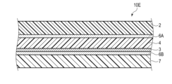
- FIG. 4 is a cross-sectional view schematically showing a laminate according to a fourth embodiment of the invention.
- FIG. 5 is a cross-sectional view schematically showing a laminate according to a fifth embodiment of the invention.
- FIG. 6 is a cross-sectional view schematically showing a laminate according to a sixth embodiment of the invention.
- FIG. 7 is a diagram schematically showing a packaged article according to a seventh embodiment of the invention.
- FIG. 8 is a diagram schematically showing a packaged article according to an eighth embodiment of the invention.
- FIG. 9 is a diagram schematically showing a packaged article according to a ninth embodiment of the invention.
- AA on BB is used regardless of the direction of gravity.
- the condition identified by the statement “AA on BB” encompasses the condition where AA is in contact with BB.
- Reference to “AA over BB” does not exclude the interposition of one or more other components between AA and BB.
- Laminate Fig. 1 is a sectional view schematically showing a laminate according to a first embodiment of the present invention.
- a laminate 10A shown in FIG. 1 includes a substrate layer 2, a gas barrier layer 3, an adhesive layer 6, and a sealant layer 7 in this order.
- 10 A of laminated bodies may further contain the printing layer between the base material layer 2 and the sealant layer 7.
- FIG. The printed layer shows characters, patterns, etc., and is provided as necessary for the purpose of displaying information about the contents, identifying the contents, or improving the design of the packaging bag.
- the description in the section of " ⁇ 2.3> Printed layer" in the second embodiment described below can be referred to.
- the ratio of polyethylene in the laminate 10A is 90% by mass or more.
- the ratio of polyethylene in the laminate 10A means the ratio of the total amount of polyethylene to the total amount of the resin material in each layer constituting the laminate 10A. High recyclability can be achieved by setting the proportion of polyethylene to 90% by mass or more.
- the base material layer 2 contains polyethylene.
- Polyethylene may be a homopolymer of ethylene or a copolymer of ethylene and other monomers. When polyethylene is a copolymer of ethylene and other monomers, the proportion of ethylene in the copolymer is, for example, 80 mol % or more.
- ⁇ -olefins include ⁇ -olefins.
- the ⁇ -olefins range from 3 to 20 carbon atoms.
- Such ⁇ -olefins are, for example, propylene, 1-butene, 1-pentene, 1-hexene, 1-octene, 1-decene, 1-dodecene, 1-tetradecene, 1-hexadecene, 1-octadecene, 1- eicosene, 3-methyl-1-butene, 4-methyl-1-pentene, or 6-methyl-1-heptene.
- the polyethylene may be a copolymer of ethylene and one of vinyl acetate and acrylic acid ester.
- the base material layer 2 is, for example, high density polyethylene (HDPE), medium density polyethylene (MDPE), low density polyethylene (LDPE), linear low density polyethylene (LLDPE), or very low density polyethylene (VLDPE).
- high-density polyethylene and medium-density polyethylene are preferable from the viewpoint of the printability, strength and heat resistance of the laminate 10A and the film stretchability, and medium-density polyethylene is more preferable from the viewpoint of stretchability.
- high-density polyethylene has a density of 0.942 g/cm 3 or more
- medium-density polyethylene has a density of 0.930 g/cm 3 or more and less than 0.942 g/cm 3
- low-density polyethylene has a density of is 0.910 g/cm 3 or more and less than 0.930 g/cm 3
- the linear low density polyethylene has a density of 0.910 g/cm 3 or more and less than 0.930 g/cm 3
- the ultra-low density polyethylene has a density of is less than 0.910 g/cm 3
- the density is a value obtained by a method conforming to JIS K7112:1999.
- the polyethylene contained in the base material layer 2 may be biomass-derived polyethylene.
- biomass-derived polyethylene for example, green polyethylene (manufactured by Braskem) can be used.
- the polyethylene contained in the base material layer 2 may be polyethylene recycled by mechanical recycling.
- mechanical recycling means pulverizing the recovered polyethylene film or the like, then cleaning the pulverized film with alkali to remove dirt and foreign matter on the film surface, and then drying it at high temperature and under reduced pressure. It is to decontaminate the polyethylene film by dispersing the retained contaminants.
- the polyethylene contained in the base material layer 2 may be polyethylene recycled by chemical recycling.
- the melting point of the base material layer 2 is preferably within the range of 100°C to 140°C, more preferably within the range of 120°C to 140°C.
- the melting point is a value obtained by a method conforming to JIS K7121-1987.
- the base material layer 2 has a birefringence ⁇ N measured by the parallel Nicols rotation method within the range of 0.01 to 0.1.
- the birefringence ⁇ N is the absolute value of the difference between the refractive index of the substrate layer 2 in the MD direction (machine direction) and the refractive index of the substrate layer 2 in the TD direction (transverse direction).
- the birefringence ⁇ N can be measured using a phase difference measuring device KOBRA-WR (manufactured by Oji Scientific Instruments Co., Ltd.).
- the light source wavelength is set to 586.6 nm, and direct measurement using the parallel Nicols rotation method is performed.
- the birefringence ⁇ N measured by the parallel Nicols rotation method is also simply referred to as “birefringence ⁇ N” in this specification.
- the birefringence ⁇ N is measured for each of multiple locations on the substrate layer 2 , and the average value of the obtained birefringence ⁇ N is obtained as the birefringence ⁇ N of the substrate layer 2 .
- the plurality of locations of the base material layer 2 are, for example, the central portion and end portions of the base material layer 2 .
- the plurality of locations of the substrate layer 2 are preferably the central portion and both ends of the TD of the substrate layer 2 .
- the birefringence ⁇ N of the base material layer 2 is preferably within the range of 0.01 to 0.052. Further, when the birefringence ⁇ N is in the range of 0.01 to 0.017, the drop strength is excellent, and when the birefringence ⁇ N is in the range of 0.017 to 0.052, the heat resistance is excellent.
- the secondary structure of the resin molecules that make up the film contributes to the large birefringence ⁇ N or large retardation.
- the basic physical properties of the film greatly change depending on the state of the molecular arrangement. Therefore, by adjusting the birefringence ⁇ N or the retardation, it becomes possible to design the functions to be imparted to the film. For example, if the anisotropy of the film is sufficiently large, it is possible to improve heat resistance and impart easy-to-cut properties. Reducing anisotropy increases toughness and improves impact resistance and puncture resistance.
- the structure formed by the resin molecules in the film is related to, for example, the crystalline state, molecular orientation, compatibility state, uneven distribution of molecules, and the like.
- the birefringence ⁇ N can be increased by uniaxially or biaxially stretching the film. When the draw ratio is large, the birefringence ⁇ N also becomes large. Also, the birefringence ⁇ N can be increased depending on the material of the base material layer 2 .
- the birefringence ⁇ N can be adjusted by stretching conditions such as the stretching ratio of the base material layer 2, film manufacturing conditions such as the density of the resin used, the type of comonomer, molecular weight, molecular weight distribution, and heat history, and the film forming method. can.
- the base material layer 2 is preferably a stretched film. Stretched films are particularly excellent in heat resistance and strength.
- the stretched film may be a uniaxially stretched film or a biaxially stretched film. In this specification, the term "film” does not include the concept of thickness.
- Using a uniaxially stretched film as the base material layer 2 improves the heat resistance during bag making.
- a biaxially stretched film is used as the base material layer 2
- the drop strength of the packaged article using the laminate 10A as the packaging material is improved.
- Whether the stretched film is a uniaxially stretched film or a biaxially stretched film can be determined by performing in-plane measurement using a wide-angle X-ray diffraction method, as described below.
- the X-ray diffraction pattern obtained by this measurement contains information on the degree of orientation of molecular chains present on the film surface. An example of the measurement method is shown.
- out-of-plane measurement is performed by the parallel beam method.
- An X-ray diffraction pattern of the film to be measured is obtained by 2 ⁇ / ⁇ scanning over a range of diffraction angles of 10° to 30°.
- CuK ⁇ rays are used as the X-rays, and the X-rays are collimated by a multilayer film mirror and made incident on the base material layer 1 .
- a scintillation detector with a flat plate collimator is used as the light receiving unit.
- the peak area of the crystalline component and the halo pattern area of the amorphous component are obtained, and the ratio of the peak area of the crystalline component to the total area is calculated as the degree of crystallinity.
- the crystallinity of one of the outermost surfaces of the film is measured.
- the film to be measured is a polyethylene film
- scanning at a diffraction angle of 10° to 30° reveals two sharp crystal component peaks corresponding to the (110) plane and the (200) plane, A broad halo pattern of the amorphous component is observed.
- the film to be measured is a uniaxially stretched film or a biaxially stretched film
- in-plane measurement by the X-ray diffraction method, as described above.
- the X-ray incident angle ⁇ and the angle 2 ⁇ at which the diffracted X-rays are detected by the detector correspond to the specific crystal planes in the above out-of-plane measurement.
- Diffraction peaks for example, the angle ⁇ and angle 2 ⁇ when the diffraction peak corresponding to the (110) plane of a polyethylene film is detected are fixed, and in this state, the film to be measured is scanned in the in-plane direction. to obtain a diffraction pattern.
- in-plane measurement is performed on a uniaxially stretched film uniaxially stretched in the machine direction (MD)
- MD direction is defined as 0 °
- a sharp diffraction peak corresponding to the (110) plane is formed at an angle 2 ⁇ of about
- a diffraction pattern with positions of ⁇ 90° can be obtained.
- biaxially stretched film the higher-order structure obtained by the uniaxial stretching is disturbed by the second stretching, and the anisotropy is reduced.
- a diffraction pattern having a uniform diffraction peak cannot be obtained. Therefore, in-plane measurements can be cited as one method of distinguishing monoaxially and biaxially stretched films from each other.
- a higher-order structure When a polymer film is uniaxially stretched, a higher-order structure called a shish kebab structure appears.
- the shish kebab structure consists of a shish structure, which is an extended chain crystal, and a kebab structure, which is a lamellar crystal.
- this higher-order structure In a uniaxially stretched film, this higher-order structure is arranged with a high degree of order, so the X-ray diffraction pattern obtained by the above measurement for the uniaxially stretched film will contain sharp diffraction peaks. That is, when the above measurement is performed on the uniaxially stretched film, a clear diffraction peak appears.
- a "clear diffraction peak” means a diffraction peak with a half width of less than 10°.
- the uniaxially stretched film and the biaxially stretched film have different X-ray diffraction patterns obtained by the above measurement. Therefore, based on this, it is possible to determine whether the stretched film is a monoaxially stretched film or a biaxially stretched film.
- a stretched film can be obtained, for example, by stretching a film obtained by forming a polyethylene film by a T-die method or an inflation method. It is also possible to use, as the substrate layer 2, a multi-layered polyethylene film obtained by co-extrusion of polyethylenes having different densities.
- a multi-layered structure comprising a layer made of high density polyethylene (high density polyethylene layer) and a layer made of medium density polyethylene (medium density polyethylene layer) may be used.
- high density polyethylene layer high density polyethylene layer
- medium density polyethylene layer medium density polyethylene layer
- the haze of the base material layer 2 is preferably 20% or less, more preferably 10% or less.
- the haze is a value obtained by a method conforming to JIS K7136:2000.
- the thickness of the base material layer 2 is preferably in the range of 10 ⁇ m to 200 ⁇ m, more preferably in the range of 15 ⁇ m to 50 ⁇ m. If the base material layer 2 is too thin, the strength of the laminate 10A tends to decrease. Moreover, if the base material layer 2 is too thick, the processability of 10 A of laminated bodies will fall easily.
- the base material layer 2 is preferably surface-treated. According to this treatment, the adhesion between the substrate layer 2 and the layer adjacent to the substrate layer 2 can be improved.
- the surface treatment method is not particularly limited.
- Surface treatments include, for example, corona discharge treatment, ozone treatment, low-temperature plasma treatment using oxygen gas and/or nitrogen gas, physical treatment such as glow discharge treatment, and chemical treatment such as oxidation treatment using chemicals. processing.
- the base material layer 2 may further contain additives.
- additives include cross-linking agents, antioxidants, anti-blocking agents, slip agents, UV absorbers, light stabilizers, fillers, reinforcing agents, antistatic agents, pigments, and modifying resins. is mentioned.
- the proportion of polyethylene in the base material layer 2 is preferably 50% by mass or more, more preferably 80% by mass or more.
- the substrate layer 2 consists of polyethylene.
- the base layer 2 consists of polyethylene and additives.
- the gas barrier layer 3 functions as a barrier layer that suppresses permeation of oxygen and water vapor.
- a gas barrier layer consists of an inorganic compound layer, or consists of an inorganic compound layer and a coating layer.
- Examples of inorganic compounds contained in the inorganic compound layer include vapor deposition layers made of metal oxides such as aluminum oxide, silicon oxide, magnesium oxide, and tin oxide.
- the metal oxide may be selected from the group consisting of aluminum oxide, silicon oxide, and magnesium oxide. Furthermore, considering the cost, it is selected from aluminum oxide and silicon oxide.
- the inorganic compound layer can be formed, for example, by vacuum deposition.
- a physical vapor deposition method or a chemical vapor deposition method can be used in vacuum deposition.
- Examples of the physical vapor deposition method include a vacuum deposition method, a sputtering method, an ion plating method, and the like, but are not limited to these.
- As the chemical vapor deposition method thermal CVD method, plasma CVD method, light C Examples include the VD method, but are not limited to these.
- the film thickness of the inorganic compound layer made of aluminum oxide is preferably 5 nm or more and 30 nm or less. Sufficient gas-barrier property can be obtained as a film thickness is 5 nm or more. Further, when the film thickness is 30 nm or less, it is possible to suppress the occurrence of cracks due to deformation due to internal stress of the thin film, and to suppress deterioration of gas barrier properties. If the film thickness exceeds 30 nm, the cost tends to increase due to an increase in the amount of material used and an increase in film formation time, which is not preferable from an economic point of view. From the same viewpoint as above, the film thickness of the inorganic compound layer is more preferably 7 nm or more and 15 nm or less.
- the film thickness of the inorganic compound layer made of silicon oxide is preferably 10 nm or more and 50 nm or less. Sufficient gas-barrier property can be obtained as a film thickness is 10 nm or more. Further, when the film thickness is 50 nm or less, it is possible to suppress the generation of cracks due to deformation due to internal stress of the thin film, and to suppress deterioration of gas barrier properties. If the film thickness exceeds 50 nm, it is not preferable from an economical point of view because the cost tends to increase due to an increase in the amount of material used and an increase in film formation time. From the same viewpoint as above, the film thickness of the inorganic compound layer is more preferably 20 nm or more and 40 nm or less.
- a known anchor coating agent may be used to form an anchor coating layer on the surface of the substrate layer 2 on which the inorganic compound layer is formed. Thereby, the adhesion of the inorganic compound layer made of metal oxide can be improved.
- anchor coating agents include polyester-based polyurethane resins and polyether-based polyurethane resins. Polyester-based polyurethane resins are preferred from the viewpoint of heat resistance and interlayer adhesive strength.
- the coating layer protects the inorganic compound layer and exhibits barrier properties independently of the inorganic compound layer.
- the coating layer can be formed using an aqueous solution containing at least one selected from the group consisting of hydroxyl-containing polymer compounds, metal alkoxides, silane coupling agents, and hydrolysates thereof.
- the thickness of the coating layer is preferably 50-1000 nm, more preferably 100-500 nm.
- the thickness of the gas barrier coating layer is 50 nm or more, it tends to be possible to obtain more sufficient gas barrier properties, and when it is 1000 nm or less, it tends to be able to maintain sufficient flexibility.
- the adhesive layer 6 contains at least one type of adhesive.
- the adhesive may be a one-component curable adhesive, a two-component curable adhesive, or a non-curable adhesive. Further, the adhesive may be a non-solvent adhesive or a solvent adhesive.
- adhesives examples include polyether adhesives, polyester adhesives, silicone adhesives, epoxy adhesives such as polyamine adhesives, urethane adhesives, rubber adhesives, vinyl adhesives, and silicone adhesives. adhesives, epoxy adhesives, phenol adhesives and olefin adhesives.
- the adhesive is preferably a polyamine-based adhesive or a urethane-based adhesive having gas barrier properties. Adhesives containing biomass components can also be preferably used.
- an epoxy-based adhesive such as a polyamine-based adhesive having gas barrier properties, or a urethane-based adhesive such as a polyester/polyurethane-based adhesive is preferably used.
- gas barrier adhesives include "Maxieve” manufactured by Mitsubishi Gas Chemical Company and "Paslim” manufactured by DIC.
- the adhesive layer 6 may be a cured product of a resin composition containing a polyester polyol, an isocyanate compound and a phosphoric acid-modified compound. Such an adhesive layer 6 is excellent in oxygen barrier properties and water vapor barrier properties of the laminate 10A.
- the thickness of the adhesive layer 6 is preferably in the range of 0.1 ⁇ m to 20 ⁇ m, more preferably in the range of 0.5 ⁇ m to 10 ⁇ m, even more preferably in the range of 1 to 5 ⁇ m. .
- the adhesive layer 6 is applied onto the substrate layer 2 by a conventionally known method such as a direct gravure roll coating method, a gravure roll coating method, a kiss coating method, a reverse roll coating method, a fonten method and a transfer roll coating method. It can be formed by drying.
- the sealant layer 7 contains polyethylene.
- the polyethylene for example, the polyethylene contained in the base material layer 2 can be used.
- the sealant layer 7 is preferably low density polyethylene (LDPE), linear low density polyethylene (LLDPE) or very high density polyethylene (VLDPE), more preferably linear low density polyethylene.
- polyethylene is preferably biomass-derived polyethylene or recycled polyethylene.
- the sealant layer 7 may be transparent or opaque. In the latter case, the sealant layer 7 may be colored, preferably white.
- the laminate 10A having a transparent sealant layer 7 makes it easy to visually recognize the contents when the laminate is used as a package.
- the laminate 10A in which the sealant layer 7 is opaque is used as a package, the content does not interfere with the visibility of the image displayed by the printed layer.
- the white sealant layer 7 improves the visibility of the image displayed by the printed layer.
- the sealant layer 7 may further contain the additives described above.
- the proportion of polyethylene in the sealant layer 7 is preferably 50% by mass or more, more preferably 80% by mass or more.
- the sealant layer 7 consists of polyethylene.
- the sealant layer 7 consists of polyethylene and additives.
- the thickness of the sealant layer 7 can be appropriately set in consideration of the shape of the packaging bag to be manufactured, the mass of the content to be contained, and the like, and can be in the range of 30 to 150 ⁇ m, for example.
- the sealant layer 7 is, for example, an unstretched polyethylene resin film or a layer formed by melt extrusion of polyethylene.
- the sealant layers of the laminate are brought into contact with each other, and the contact portions are sandwiched between jigs to apply pressure and heat, thereby heat-sealing the contact portions.
- the jig of the heat-sealing machine is at a high temperature, and the surface of the base material layer in direct contact with the jig is exposed to high temperature.
- polyethylene which is inferior in heat resistance
- the surface of the substrate layer may be affected by heat, causing problems such as adhesion to jigs. Therefore, conventional laminates using polyethylene as a base layer have a problem of poor productivity due to narrow appropriate bag-making temperature conditions.
- the present inventors have found that when the birefringence ⁇ N of the base layer 2 is within the range of 0.01 to 0.1, the base layer 2 exhibits excellent heat resistance, and therefore the laminate 10A is also excellent. It has been found to exhibit heat resistance, in particular to achieve good heat-sealability.
- polyethylene which is generally said to have poor heat resistance
- the birefringence ⁇ N of the base material layer 2 within the range of 0.01 to 0.1, the temperature range of heat-sealing for bag making is widened, and productivity does not decrease.
- the laminate 10A has a polyethylene content of 90% by mass or more. Therefore, the laminate 10A is also excellent in recyclability.
- the laminate 10A may be further provided with a print layer, a protective layer, a light shielding layer, other functional layers, and the like, if necessary.
- the laminate 10A may further include a printed layer between the base material layer 2 and the sealant layer 7. That is, the printed layer may be provided at any position between the base material layer 2 and the sealant layer 7 .
- the printed layer can be provided between the substrate layer 2 and the gas barrier layer 3 (that is, the back surface of the substrate layer 2). In this case, when the laminate 10A is observed from the base material layer 2 side, the pattern displayed by the printed layer is likely to be clearly visible.
- the printed layer may be provided on the surface of the base material layer 2 . Also, a plurality of printed layers may be provided.
- an anchor coat layer may be formed on the main surface of the base material layer 2 that faces the gas barrier layer 3 .
- the gas barrier layer 3 may be omitted.
- a metal deposition layer may be provided on the base material layer 2 or the sealant layer 7 in order to impart light shielding properties to the laminate 10A.
- a metal deposition layer may be provided on the intermediate layer.
- An aluminum vapor deposition layer can be mentioned as a metal vapor deposition layer.
- the sealant layer 7 may be opaque
- the base layer 2 may also be opaque.
- the substrate layer 2 may be colored, for example white.
- the intermediate layer may be opaque.
- the intermediate layer may be colored, for example white.
- FIG. 2 is a cross-sectional view schematically showing a laminate according to a second embodiment of the present invention.
- the laminate 10B shown in FIG. 2 further includes a protective layer 1 provided on the surface of the base material layer 2, and further includes a printed layer 5 between the gas barrier layer 3 and the adhesive layer 6. Other than that, it is the same as the laminate 10A. That is, the laminate 10B shown in FIG. 2 includes a protective layer 1, a base material layer 2, a gas barrier layer 3, a printing layer 5, an adhesive layer 6, and a sealant layer 7 in this order.
- the protective layer 1 is the outermost layer facing the sealant layer 7 with the base material layer 2 interposed therebetween. Here, the protective layer 1 covers the surface of the base material layer 2 .
- the protective layer 1 is made of a thermosetting resin. That is, the protective layer 1 is a thermosetting resin layer.
- the cured product of the thermosetting resin is not particularly limited as long as it has heat resistance.
- Thermosetting resins include, for example, polyurethane resins, polyester resins, polyamide resins, polyamideimide resins, acrylic resins, and epoxy resins.
- the protective layer 1 may contain one type of the above thermosetting resin, or may contain two or more types.
- the protective layer 1 preferably contains a water-soluble polymer, and is preferably an organic-inorganic composite layer containing an organometallic compound.
- water-soluble polymers examples include polyvinyl alcohol, polysaccharides such as starch, methylcellulose, carboxymethylcellulose, and hydroxyl group-containing polymers such as acrylic polyol.
- the protective layer 1 preferably contains a polyvinyl alcohol-based hydroxyl group-containing polymer that can be contained in a coating layer as the gas barrier layer 3 described later.
- the protective layer 1 preferably contains at least one of a metal alkoxide, a hydrolyzate of a metal alkoxide, and a reaction product of a metal alkoxide or a hydrolyzate thereof as an organometallic compound.
- metal alkoxides include those represented by the general formula M(OR) n such as tetraethoxysilane [Si( OC2H5 ) 4 ] and triisopropoxyaluminum [Al( OC3H7 ) 3 ]. mentioned.
- the protective layer 1 further includes at least one of a silane coupling agent, a hydrolyzate of the silane coupling agent, and a reaction product of the silane coupling agent or a hydrolyzate of the silane coupling agent as the organometallic compound. It is preferred to include
- the protective layer 1 can be formed using a coating liquid for forming a coating layer as the gas barrier layer 3, which will be described later. Further, when the laminate 10B includes an inorganic compound layer and a coating layer as the gas barrier layer 3, the protective layer 1 is a layer formed using the same coating liquid as the coating liquid used to form the coating layer. you can
- the thickness of the protective layer 1 When the thickness of the protective layer 1 becomes thin, it tends to become difficult to achieve high heat resistance.
- the thickness of the protective layer 1 is preferably 0.3 ⁇ m or more in order to reduce or mitigate thermal damage during heat sealing. Moreover, when the thickness of the protective layer 1 increases, it tends to become difficult to sufficiently dry the resin coating film in the manufacturing process of the laminate 10B. From the viewpoint of productivity, the thickness of protective layer 1 is preferably 3 ⁇ m or less.
- the print layer 5 is a layer made of ink and displays patterns such as characters and pictures.
- the inks are, for example, conventionally used ink binder resins such as urethane, acrylic, nitrocellulose, rubber, and vinyl chloride, various pigments, extenders, plasticizers, desiccants, stabilizers, etc. of additives are added.
- As the ink it is preferable to use biomass-derived ink.
- a light-shielding ink can also be preferably used. Examples of light-shielding ink include white ink, black ink, silver ink, and sepia ink.
- Examples of methods for forming the printing layer 5 include known printing methods such as offset printing, gravure printing, flexographic printing, and silk screen printing, and known printing methods such as roll coating, knife edge coating, and gravure coating.
- a coating method can be used.
- the laminate 10B includes the protective layer 1 .
- the protective layer 1 reduces thermal damage during heat sealing on the surface of the laminate 10B. Therefore, the laminate 10B can achieve even better heat resistance, particularly better heat-sealability. Therefore, when the laminate 10B has the configuration described above, the temperature range for heat sealing for bag making is widened, and the decrease in productivity is less likely to occur.
- the protective layer 1 is substantially transparent, even if the laminate 10B further includes the protective layer 1, the image displayed by the printed layer 5 can be visually recognized from the surface side. That is, the laminate 10B has excellent transparency and further excellent heat resistance. Moreover, since the laminate 10B has a ratio of polyethylene of 90% by mass or more, it is also excellent in recyclability.
- the laminate 10B includes the printed layer 5 between the gas barrier layer 3 and the adhesive layer 6. may be provided at any position. Since the base material layer 2 is transparent, even when the printed layer 5 is included between the protective layer 1 and the sealant layer 7, the printed layer 5 is visible when the laminate 10B is observed from the protective layer 1 side. You can clearly see the pattern. Alternatively, the print layer 5 may be omitted.
- an anchor coat layer may be formed on the main surface of the base material layer 2 that faces the gas barrier layer 3 .
- the gas barrier layer 3 may be omitted.
- Laminate Fig. 3 is a sectional view schematically showing a laminate according to a third embodiment of the present invention.
- a laminate 10C shown in FIG. 3 is the same as the laminate 10A except for the following items. That is, the laminate 10C further includes the intermediate layer 4 and the print layer 5. As shown in FIG. Also, the laminate 10C includes a first adhesive layer 6A and a second adhesive layer 6B instead of the adhesive layer 6. As shown in FIG. That is, the laminate 10C includes the base material layer 2, the first adhesive layer 6A, the gas barrier layer 3, the intermediate layer 4, the printing layer 5, the second adhesive layer 6B, and the sealant layer 7. Including in order.
- the intermediate layer 4 is interposed between the base material layer 2 and the sealant layer 7 .
- the intermediate layer 4 contains polyethylene.
- the intermediate layer 4 has a birefringence ⁇ N measured by the parallel Nicols rotation method within the range of 0.01 to 0.1, preferably within the range of 0.01 to 0.052.
- Such an intermediate layer 4 can contribute to improving the strength of the laminate 10C, particularly the puncture strength.
- the "puncture strength" of the laminate is a value obtained when the laminate 10C is pierced from the base layer 2 side in the method specified in JIS Z1707:2019 "General Rules for Plastic Films for Food Packaging". Specifically, a needle with a diameter of 1 mm and a semicircular tip is pierced into the laminated body 10C from the base layer 2 side at a speed of 50 mm/min, and the maximum force until the needle penetrates is measured. do. This measurement is performed multiple times and the arithmetic mean of the maximum force is obtained as the puncture strength.
- the intermediate layer 4 is for example high density polyethylene (HDPE), medium density polyethylene (MDPE), low density polyethylene (LDPE), linear low density polyethylene (LLDPE) or very low density polyethylene (VLDPE).
- high-density polyethylene and medium-density polyethylene are preferable from the viewpoint of printability, strength and heat resistance of the laminate 10C, and film stretchability, and medium-density polyethylene is more preferable from the viewpoint of stretchability.
- the polyethylene contained in the intermediate layer 4 may be the same as or different from the polyethylene contained in the base material layer 2.
- the intermediate layer 4 may further contain the additives described above.
- the proportion of polyethylene in the intermediate layer 4 is preferably 50% by mass or more, more preferably 80% by mass or more.
- the intermediate layer 4 consists of polyethylene.
- the intermediate layer 4 consists of polyethylene and additives.
- the melting point of the intermediate layer 4 is preferably within the range of 100°C to 140°C, more preferably within the range of 120°C to 140°C.
- the intermediate layer 4 is preferably a stretched film.
- the stretched film may be a uniaxially stretched film or a biaxially stretched film.
- the stretched film forming the intermediate layer 4 may be the same as or different from the stretched film forming the base layer 2 .
- Using a uniaxially stretched film as the intermediate layer 4 improves the heat resistance during bag making.
- a biaxially oriented film is used as the intermediate layer 4, the drop strength of the packaged article using the laminate 10C as the packaging material is improved.
- the stretched film is a uniaxially stretched film or a biaxially stretched film can be determined by performing in-plane measurement using the X-ray diffraction method, as described in the section of the first embodiment.
- the thickness of the intermediate layer 4 is preferably in the range of 10 ⁇ m to 200 ⁇ m, more preferably in the range of 15 ⁇ m to 50 ⁇ m.
- the intermediate layer 4 one produced by the above-described T-die method or inflation method may be used.
- the intermediate layer 4 is preferably surface-treated, like the base material layer 2 . According to this treatment, the adhesion between the intermediate layer 4 and the adjacent layer can be improved.
- the surface treatment method is not particularly limited. Surface treatments include, for example, corona discharge treatment, ozone treatment, low-temperature plasma treatment using oxygen gas and/or nitrogen gas, physical treatment such as glow discharge treatment, and chemical treatment such as oxidation treatment using chemicals. processing.
- an intermediate layer having a birefringence ⁇ N of 0 to 0.01 as measured by the parallel Nicols rotation method may be used.
- an intermediate layer having a birefringence ⁇ N in this range the strength of the laminate 10C, particularly drop strength, can be improved.
- the intermediate layer having a birefringence ⁇ N of 0 to 0.01 is preferably an unstretched film.
- Adhesive Layer The first adhesive layer 6A is interposed between the base material layer 2 and the gas barrier layer 3 and bonds them together.
- the second adhesive layer 6B is interposed between the printed layer 5 and the sealant layer 7 to bond them together.
- the adhesive for forming the first adhesive layer 6A and the second adhesive layer 6B As the adhesive for forming the first adhesive layer 6A and the second adhesive layer 6B, the adhesive described in the section " ⁇ 1.5> Adhesive layer" in the first embodiment can be used. can.
- the material of the second adhesive layer 6B may be the same as or different from the material of the first adhesive layer 6A.
- the thickness of the first adhesive layer 6A and the second adhesive layer 6B is preferably in the range of 0.1 ⁇ m to 20 ⁇ m, more preferably in the range of 0.5 ⁇ m to 10 ⁇ m, and 1 to 5 ⁇ m. is more preferably within the range of
- the first adhesive layer 6A and the second adhesive layer 6B are formed, for example, by a conventionally known method such as a direct gravure roll coating method, a gravure roll coating method, a kiss coating method, a reverse roll coating method, a fonten method and a transfer roll coating method. It can be formed by coating and drying on the base material layer 2 or the sealant layer 7 .
- the laminated body 10C is excellent in heat resistance like the laminated body 10A.
- the laminate 10C also includes an intermediate layer 4 having a birefringence ⁇ N within the range of 0.01 to 0.1. This intermediate layer 4 enhances the strength of the laminate 10C, especially the puncture strength. Therefore, the laminate 10C is excellent in strength, especially puncture strength.
- the laminate 10C has a polyethylene ratio of 90% by mass or more, it is also excellent in recyclability.
- laminates with a high proportion of polyethylene are weaker in stiffness than other laminates, and are therefore more likely to be bent when used as packaging materials. As the chances of bending increase, the possibility of pinhole formation increases.
- the laminated body 10C which has excellent piercing strength, is less prone to pinhole formation.
- the laminate 10C includes the printed layer 5 between the intermediate layer 4 and the second adhesive layer 6B.
- the print layer 5 may be omitted.
- an anchor coat layer may be formed on the main surface facing the first adhesive layer 6A.
- the laminate 10C includes the gas barrier layer 3 between the first adhesive layer 6A and the intermediate layer 4, but the laminate 10C includes the intermediate layer 4 and the second adhesive layer 6B.
- a gas barrier layer 3 may be included between.
- the gas barrier layer 3 may be omitted.
- Laminate Fig. 4 is a sectional view schematically showing a laminate according to a fourth embodiment of the present invention.
- a layered body 10D shown in FIG. 4 is the same as the layered body 10C except that it further includes a protective layer 1 provided on the surface of the base material layer 2 and that the layering order is partially different. That is, the laminate 10D includes a protective layer 1, a base layer 2, a printing layer 5, a first adhesive layer 6A, an intermediate layer 4, a gas barrier layer 3, a second adhesive layer 6B, and a sealant. layer 7 in that order.
- the protective layer 1 As the protective layer 1, the one described in the second embodiment can be used.
- the printed layer 5 is provided between the base material layer 2 and the first adhesive layer 6A. In this case, when the laminated body 10D is observed from the protective layer 1 side, the pattern displayed by the printed layer 5 can be seen more clearly.
- the birefringence ⁇ N of the base material layer 2 is within the range of 0.01 to 0.1.
- the laminated body 10 ⁇ /b>D includes a protective layer 1 . Therefore, the laminate 10D can achieve even better heat resistance, particularly better heat-sealability. Therefore, if the laminate 10D has the configuration described above, the temperature range for heat-sealing for bag making is widened, and productivity is less likely to decrease.
- the protective layer 1 is substantially transparent, even if the laminate 10D further includes the protective layer 1, the image displayed by the printed layer 5 can be visually recognized from the surface side. That is, the laminated body 10D is transparent and further excellent in heat resistance.
- the laminate 10D also includes an intermediate layer 4 having a birefringence ⁇ N within the range of 0.01 to 0.1.
- This intermediate layer 4 enhances the strength of the laminate 10D, especially the puncture strength. Therefore, the laminate 10D is excellent in strength, especially puncture strength.
- the laminate 10D has a polyethylene ratio of 90% by mass or more, it is also excellent in recyclability.
- the laminate 10D includes the printed layer 5 between the base material layer 2 and the first adhesive layer 6A.
- the printed layer 5 includes the protective layer 1 and the sealant layer 7 may be provided at any position between Since the base material layer 2 and the intermediate layer 4 are transparent, the laminate 10D can be observed from the protective layer 1 side regardless of where the printed layer 5 is included between the protective layer 1 and the sealant layer 7. In this case, the pattern displayed by the printed layer 5 can be clearly seen. Alternatively, the print layer 5 may be omitted.
- an anchor coat layer may be formed on the main surface of the base material layer 2 that faces the printed layer 5 .
- the gas barrier layer 3 may be omitted.
- FIG. 5 is a cross-sectional view schematically showing a laminate according to a fifth embodiment of the present invention.
- the intermediate layer 4 is interposed between the base material layer 2 and the sealant layer 7 .
- the intermediate layer 4 contains polyethylene.
- the intermediate layer 4 has a birefringence ⁇ N within the range of 0 to 0.01, preferably 0 or more and less than 0.01.
- the intermediate layer 4 is preferably an unstretched film. Such an intermediate layer 4 improves adhesion between the intermediate layer 4 and the gas barrier layer 3, thereby making it difficult to separate the base layer 2 and the sealant layer 7 from each other in the laminate 10E.
- an intermediate layer having a birefringence ⁇ N of 0.01 to 0.1 as measured by the parallel Nicols rotation method may be used.
- the strength of the laminate 10E, particularly the puncture strength can be improved.
- the intermediate layer having a birefringence ⁇ N of 0.01 to 0.1 is preferably a stretched film.
- a pretreatment layer (that is, an anchor coat layer) may be provided on the surface of the intermediate layer 4 on which the gas barrier layer 3 is provided.
- the pretreatment layer By providing the pretreatment layer, the film-forming properties and adhesion strength of the gas barrier layer 3 can be improved.
- the components and forming method of the pretreatment layer can be selected from thermoplastic resins, thermosetting resins, ultraviolet curable resins, plasma treatment, and the like.
- the content of the organic polymer in the pretreatment layer may be, for example, 70% by mass or more, or may be 80% by mass or more.
- organic polymers include polyacrylic resins, polyester resins, polycarbonate resins, polyurethane resins, polyamide resins, polyolefin resins, polyimide resins, melamine resins, and phenol resins. Considering this, it is preferable to include at least one of a polyacrylic resin, a polyol resin, a polyurethane resin, a polyamide resin, or a reaction product of these organic polymers.
- the pretreatment layer may also contain a silane coupling agent, organic titanate, or modified silicone oil.
- the organic polymer used in the pretreatment layer is an organic polymer having a urethane bond generated by a reaction between a polyol having two or more hydroxyl groups at the polymer end and an isocyanate compound, and/or a polymer.
- Organic polymers include reaction products of polyols having two or more terminal hydroxyl groups and organosilane compounds such as silane coupling agents or hydrolysates thereof.
- polyols include at least one selected from acrylic polyols, polyvinyl acetals, polystyrene polyols, polyurethane polyols, and the like.
- the acrylic polyol may be obtained by polymerizing an acrylic acid derivative monomer, or may be obtained by copolymerizing an acrylic acid derivative monomer and another monomer.
- Acrylic acid derivative monomers include ethyl methacrylate, hydroxyethyl methacrylate, hydroxypropyl methacrylate, and hydroxybutyl methacrylate.
- monomers to be copolymerized with acrylic acid derivative monomers include styrene.
- the isocyanate compound has the effect of increasing the adhesion between the intermediate layer 4 and the gas barrier layer 3 through the urethane bond formed by reacting with the polyol. That is, the isocyanate compound functions as a cross-linking agent or curing agent.
- isocyanate compounds include monomers such as aromatic tolylene diisocyanate (TDI), diphenylmethane diisocyanate (MDI), aliphatic xylene diisocyanate (XDI), hexamethylene diisocyanate (HMDI), and isophorone diisocyanate (IPDI). , polymers thereof, and derivatives thereof.
- the isocyanate compounds described above may be used singly or in combination of two or more.
- silane coupling agents examples include vinyltrimethoxysilane, ⁇ -chloropropylmethyldimethoxysilane, ⁇ -chloropropyltrimethoxysilane, glycidoxypropyltrimethoxysilane, ⁇ -methacryloxypropyltrimethoxysilane, and ⁇ - methacryloxypropylmethyldimethoxysilane and the like.
- the organosilane compound may be a hydrolyzate of these silane coupling agents.
- the organic silane compound may contain one of the above-mentioned silane coupling agents and hydrolysates thereof alone or in combination of two or more thereof.
- the resin layer provided as the pretreatment layer can be formed by mixing the above-described components in an organic solvent at an arbitrary ratio to prepare a mixed solution, and applying the prepared mixed solution to the intermediate layer 4 .
- the mixture includes, for example, tertiary amines, imidazole derivatives, carboxylic acid metal salt compounds, quaternary ammonium salts, quaternary phosphonium salts and other curing accelerators; phenolic, sulfur, and phosphite antioxidants; A leveling agent; a flow control agent; a catalyst; a cross-linking reaction accelerator;
- the mixture is applied to one side of the intermediate layer 4 using a known printing method such as offset printing, gravure printing, or silk screen printing, or a known coating method such as roll coating, knife edge coating, or gravure coating.
- a pretreatment layer can be formed by heating to, for example, 50 to 200° C. and drying and/or curing.
- the thickness may be adjusted according to the application or required properties, but is preferably 0.01 to 1 ⁇ m, more preferably 0.01 to 0.5 ⁇ m. If the thickness of the pretreatment layer is 0.01 ⁇ m or more, sufficient adhesion strength between the intermediate layer 4 and the gas barrier layer 3 can be obtained, and the gas barrier properties are also improved. If the thickness of the pretreatment layer is 1 ⁇ m or less, it is easy to form a uniform coating surface, and the drying load and manufacturing cost can be suppressed.
- in-line plasma treatment is preferable from the viewpoint of productivity.
- the method of plasma treatment is not particularly limited, such as glow discharge, and a magnet may be used to increase the plasma density.
- Gas used for plasma treatment can be selected from one or more of oxygen, nitrogen, and argon.
- the birefringence ⁇ N of the base material layer 2 is in the range of 0.01 to 0.1. Therefore, the layered product 10E is excellent in heat resistance like the layered product 10A. Furthermore, the laminate 10E is excellent in tearability. Therefore, the packaging bag manufactured from the laminate 10E can be easily opened by hand. This effect will be explained below.
- the problem with laminates made by laminating multiple resin films is that they have high tear strength.
- the inventors have found that the tear strength of the laminate 10E can be reduced when the birefringence ⁇ N of the base material layer 2 is within the range of 0.01 to 0.1.
- "good tearability" means that the tear strength is 100 N/mm or less.
- the tear strength is a value measured by the trouser tear method in accordance with JIS K 7128-1. Tear strength values can vary depending on the direction of tearing, but a sufficiently low tear strength in one direction can form a packaging material that is easy to open. Based on this, the tear strength in the present invention is measured in the MD direction and the TD direction, and the lower value is adopted.
- the laminate 10E includes an intermediate layer 4 having a birefringence ⁇ N within the range of 0 to 0.01, preferably 0 or more and less than 0.01. As described above, such an intermediate layer 4 improves the adhesion between the intermediate layer 4 and the gas barrier layer 3, thereby making it difficult to separate the base layer 2 and the sealant layer 7 from each other in the laminate 10E. can.
- the laminate 10E has a polyethylene ratio of 90% by mass or more, it is also excellent in recyclability.
- the laminate 10E may be further provided with a print layer, a protective layer, a light shielding layer, other functional layers, and the like, if necessary.
- the printed layer may be provided at any position between the base layer 2 and the intermediate layer 4. Since the substrate layer 2 is transparent, even when the printed layer is included between the substrate layer 2 and the intermediate layer 4, when the laminate 10E is observed from the substrate layer 2 side, the printed layer is visible. The displayed pattern can be clearly seen.
- the printed layer can be provided between the substrate layer 2 and the first adhesive layer 6A.
- the gas barrier layer 3 may be provided on the surface on the base layer 2 side instead of the surface on the sealant layer 7 side. Alternatively, the gas barrier layer 3 may be provided on both surfaces of the intermediate layer 4 . Alternatively, the gas barrier layer 3 may be omitted.
- Laminate Fig. 6 is a sectional view schematically showing a laminate according to a sixth embodiment of the present invention.
- the laminate 10F shown in FIG. 6 further includes a protective layer 1 provided on the surface of the base material layer 2, and further includes a printed layer 5 between the base material layer 2 and the first adhesive layer 6A. It is the same as the laminate 10E except that it is included.
- the protective layer 1 the one described in the second embodiment can be used.
- the printing layer 5 the one described in the second embodiment can be used.
- the birefringence ⁇ N of the base material layer 2 is within the range of 0.01 to 0.1.
- the laminate 10F includes a protective layer 1. As shown in FIG. Therefore, the laminate 10F can achieve even better heat resistance, particularly better heat-sealability. Therefore, if the laminate 10F has the configuration described above, the temperature range for heat-sealing for bag making is widened, and productivity is less likely to decrease.
- the protective layer 1 is substantially transparent, even if the laminate 10F further includes the protective layer 1, the image displayed by the printed layer 5 can be visually recognized from the surface side. That is, the laminated body 10F is transparent and further excellent in heat resistance.
- the laminate 10F includes an intermediate layer 4 having a birefringence ⁇ N within the range of 0 to 0.01, preferably 0 or more and less than 0.01.
- the intermediate layer 4 enhances the strength of the laminate 10F, particularly drop strength. That is, in the laminate 10F, the intermediate layer 4 positioned inside the base material layer 2 is softer than the base material layer 2 when used in a package. This structure is suitable for absorbing the impact that occurs when a packaged article using the laminate 10F as a packaging material is dropped. Therefore, a packaged article using the laminate 10F as a packaging material is less likely to be damaged (broken bag) due to dropping. Therefore, the laminate 10F is excellent in strength, particularly drop strength.
- the laminate 10F has a polyethylene ratio of 90% by mass or more, it is also excellent in recyclability.
- the laminate 10F includes the printed layer 5 between the base material layer 2 and the first adhesive layer 6A. may be provided at any position between Since the substrate layer 2 is transparent, even when the printed layer 5 is included between the protective layer 1 and the intermediate layer 4, when the laminate 10F is observed from the protective layer 1 side, the printed layer 5 is visible. The displayed pattern can be clearly seen. Alternatively, the print layer 5 may be omitted.
- the gas barrier layer 3 may be provided on the surface on the base layer 2 side instead of the surface on the sealant layer 7 side. Alternatively, the gas barrier layer 3 may be provided on both surfaces of the intermediate layer 4 . Alternatively, the gas barrier layer 3 may be omitted.
- FIG. 7 is a diagram schematically showing a packaged product according to a seventh embodiment of the present invention.
- a packaged article 100A shown in FIG. 7 includes a package 110A and contents housed therein.
- the package 110A is a flat pouch.
- the package 110A includes a pair of main body films.
- Each of the main films is either one of the laminates described in the first to sixth embodiments, or is cut from it.
- the body films are stacked with their sealant layers facing each other and heat sealed to each other at their peripheral edges.
- the package 110A is provided with a notch as an easy-to-open structure in its heat-sealed portion.
- the contents may be liquid, solid, or a mixture thereof.
- the content is, for example, food or medicine.
- FIG. 8 is a diagram schematically showing a packaged product according to an eighth embodiment of the present invention.
- a packaged article 100B shown in FIG. 8 includes a package 110B and contents accommodated therein.
- the contents are, for example, the same as those described for the packaged article 100A.
- the package 110B is a standing pouch.
- Package 110B includes a pair of main and bottom films. Each of these films is, or is cut from, any of the laminates described in the first through sixth embodiments.
- a pair of main body films are superimposed so that their sealant layers face each other, and their peripheral edges are heat-sealed to each other except for one end and a region in the vicinity thereof.
- the bottom film is folded in two so as to form a mountain fold when viewed from the sealant layer side, and is sandwiched between the pair of main films at the position of the one end so that the mountain fold faces the other end of the main film. .
- the bottom film is heat-sealed to the pair of main films except for the central portion. Further, the outer surfaces of the bottom film are adhered to each other at positions on both sides of the bottom of the package 110B.
- the package 110B is provided with a notch as an easy-to-open structure in the portion where the main films are heat-sealed.
- the easy-open structure may be provided so that when the packaged article 100B is opened, the upper corner can be used as a mouth.
- the packaged article 100B may further include the spout member and lid described in the ninth embodiment.
- FIG. 9 is a diagram schematically showing a packaged product according to a ninth embodiment of the present invention.
- a packaged product 100C shown in FIG. 9 includes a package 110C and contents housed therein.
- the contents are, for example, the same as those described for the packaged article 100A.
- the package 110C is a gusset type pouch.
- the package 110C includes a container body 110C1, a mouth member 110C2, and a lid 110C3.
- the container body 110C1 includes a pair of body films and a pair of side films.
- a pair of main body films are superimposed so that their sealant layers face each other and part of the mouth member 110C2 is sandwiched between one ends.
- the peripheral edge portions of these main films are heat-sealed to the mouth member 110C2 at the one end and heat-sealed to each other in the vicinity thereof.
- the peripheral edge portions of these main films are heat-sealed to each other at the opposite ends except for the areas on both sides.
- Each of the side films is folded in two so as to form a mountain fold when viewed from the sealant layer side. These side films are sandwiched between a pair of main films on both sides of the main films so that the mountain folds face each other.
- Each of the side films has a portion of its peripheral edge heat-sealed to one of the body films and the remaining portion of its peripheral edge heat-sealed to the other of the body films.
- the outer surfaces of the side films are adhered to each other at the upper and lower positions of the package 110C.
- the container body 110C1 may further include a bottom film.
- the mouth member 110C2 includes a portion that is sandwiched between the main films and that are heat-sealed.
- the mouth member 110C2 further includes a mouth protruding outward from the container body 110C1.
- the mouth portion has a substantially cylindrical shape and is provided with a male thread on the outer surface of the side wall.
- the lid 110C3 has a cylindrical shape with a bottom.
- the lid 110C3 has a female screw on the inner side wall and is screwed with the mouth of the mouth member 110C2.
- Test A (1.1) Production of laminate (1.1.0) Preparation of coating solution (Preparation of mixed solution for gas barrier coating layer) A liquid, B liquid, and C liquid shown below were mixed in a mass ratio of 70/20/10, respectively, to obtain a mixed liquid for a gas barrier coating layer.
- a solution Solid content 5% by mass ( SiO 2 equivalent) hydrolysis solution.
- B solution 5 mass % water/methanol solution of polyvinyl alcohol (mass ratio of water:methanol is 95:5).
- Solution C 1,3,5-tris(3-trimethoxysilylpropyl)isocyanurate was diluted with a mixture of water/isopropyl alcohol (mass ratio of water:isopropyl alcohol is 1:1) to a solid content of 5% by mass. Hydrolysis solution.
- Adhesive for Adhesive Layer Formation Two types of adhesives used for the adhesive layer are shown below.
- ⁇ Urethane-based adhesive An adhesive obtained by mixing 100 parts by mass of Takelac A525 manufactured by Mitsui Chemicals, 11 parts by mass of Takenate A52 manufactured by Mitsui Chemicals, and 84 parts by mass of ethyl acetate ⁇ Gas barrier adhesive Ethyl acetate and methanol
- Example 1A A polyethylene film (thickness: 25 ⁇ m, density: 0.950 g/cm 3 , birefringence ⁇ N: 0.0238, single-sided corona treatment) was used as the substrate layer, and one surface of the substrate layer was coated with a vacuum deposition apparatus using an electron beam heating method. was used to form a silicon oxide layer having a thickness of 10 nm, and an inorganic compound layer was formed as a gas barrier layer.
- a pattern was printed on the inorganic compound layer by gravure printing to form a printed layer.
- the urethane-based adhesive was applied on the printed layer by gravure coating and dried to form an adhesive layer with a thickness of 3 ⁇ m.
- a 60 ⁇ m-thick film made of LLDPE was used as the sealant layer.
- the printed layer and the sealant layer were coated with the above urethane-based adhesive by gravure coating and dried to form an adhesive layer having a thickness of 3 ⁇ m, and the respective layers were adhered by dry lamination. Thus, a laminate according to Example 1A was obtained.
- Example 2A A laminate according to Example 2A was obtained in the same manner as in Example 1A except that the printed layer and the sealant layer were laminated via the urethane-based adhesive without forming the inorganic compound layer.
- Example 3A A laminate according to Example 3A was obtained in the same manner as in Example 1A, except that the polyamine-based gas barrier adhesive was used as the adhesive.
- Example 4A was prepared in the same manner as in Example 1A, except that the gas barrier coating layer mixture was applied onto the inorganic compound layer by gravure coating, dried and cured to form a coating layer having a thickness of 0.3 ⁇ m. was obtained.
- the gas barrier layer consists of an inorganic compound layer and a coating layer.
- Example 5A A laminate according to Example 5A was prepared in the same manner as in Example 4A, except that a polyethylene film (thickness 25 ⁇ m, density 0.950 g/cm 3 , birefringence ⁇ N 0.0412, single-sided corona treatment) was used as the base layer. got
- Example 6A A laminate according to Example 6A was prepared in the same manner as in Example 4A, except that a polyethylene film (thickness 25 ⁇ m, density 0.950 g/cm 3 , birefringence ⁇ N 0.0119, corona treatment on one side) was used as the base layer. got
- Example 7A A laminate according to Example 7A was prepared in the same manner as in Example 1A, except that a polyethylene film (thickness 20 ⁇ m, density 0.950 g/cm 3 , birefringence ⁇ N 0.0238, single-sided corona treatment) was used as the base layer. got
- Example 8A A laminate according to Example 8A was prepared in the same manner as in Example 1A, except that a polyethylene film (thickness 30 ⁇ m, density 0.950 g/cm 3 , birefringence ⁇ N 0.0238, single-sided corona treatment) was used as the base layer. got
- Example 9A A laminate according to Example 9A was obtained in the same manner as in Example 1A except that a linear low-density polyethylene resin (LLDPE) film having a thickness of 40 ⁇ m was used as the sealant layer.
- LLDPE linear low-density polyethylene resin
- Example 10A A laminate according to Example 10A was obtained in the same manner as in Example 1A except that a linear low-density polyethylene resin (LLDPE) film having a thickness of 120 ⁇ m was used as the sealant layer.
- LLDPE linear low-density polyethylene resin
- Example 11A A laminate according to Example 11A was obtained in the same manner as in Example 1A except that no inorganic compound layer was formed and a polyamine gas barrier adhesive was used instead of the urethane adhesive.
- Example 12A Lamination according to Example 12A was performed in the same manner as in Example 1A, except that no inorganic compound layer was formed and a urethane-based gas barrier adhesive was used instead of the urethane-based adhesive. got a body
- Comparative Example 1A Lamination according to Comparative Example 1A was carried out in the same manner as in Example 1A, except that a polyethylene film (thickness 32 ⁇ m, density 0.950 g/cm 3 , birefringence ⁇ N 0.0029, corona treatment on one side) was used as the substrate layer. got a body
- Comparative Example 2A Lamination according to Comparative Example 2A was performed in the same manner as in Example 1A, except that a polyethylene film (thickness 25 ⁇ m, density 0.952 g/cm 3 , birefringence ⁇ N 0.0051, corona treatment on one side) was used as the substrate layer. got a body
- Evaluation method (1.2) Evaluation method (1.2.1) Evaluation method for heat resistance at 140 ° C. Cut out a sample piece of 10 cm square from the above laminate, fold it in two so that the sealant layer is on the inside, and use a heat seal tester. was heat-sealed under the conditions of 140° C., 0.1 MPa, and 1 second. The resulting heat-sealed sample piece was visually evaluated based on the following evaluation criteria. A: The surface is not melted and there is no problem in appearance. B: The surface is melted and there is a problem in appearance.
- An overcoat agent was prepared by mixing the following A liquid, B liquid, and C liquid at a mass ratio of 70/20/10, respectively.
- Solution A Solid content of 5% by mass ( SiO 2 equivalent) hydrolysis solution.
- B solution 5 mass % water/methanol solution of polyvinyl alcohol (mass ratio of water:methanol is 95:5).
- Solution C 1,3,5-tris(3-trialkoxysilylpropyl) isocyanurate was diluted with a mixture of water/isopropyl alcohol (mass ratio of water:isopropyl alcohol was 1:1) to a solid content of 5% by mass. Hydrolysis solution.
- Example 1B A laminate 10B shown in FIG. 2 was manufactured by the following method. First, as the base material layer 2, the following films were prepared. The prepared film consisted of polyethylene and had a birefringence ⁇ N of 0.0238, a haze of 1.6%, a thickness of 25 ⁇ m and a density of 0.950 g/cm 3 as measured by the method described above. Yes, one side corona treated.
- the above-mentioned "coating solution for forming a protective layer” was applied by gravure coating and dried to form a protective layer having a thickness of 0.5 ⁇ m. .
- a 40 nm-thick inorganic compound layer composed of a silicon oxide (SiOx) deposited film is formed using an electron beam heating type vacuum deposition device, and , the above-mentioned "coating liquid for coating layer formation", that is, the organic/inorganic coating mixed liquid was applied to form a coating layer having a thickness of 0.3 ⁇ m.
- a gas barrier layer 3 composed of an inorganic compound layer and a coating layer was formed.
- FIG. 2 shows a schematic cross-sectional view of a laminate 10B according to Example 1B.
- Example 2B A laminate according to Example 2B was produced in the same manner as the laminate according to Example 1B, except that the following films were used as the base material layer 2 .
- the film used consisted of polyethylene and had a birefringence ⁇ N of 0.0119, a haze of 5.9%, a thickness of 25 ⁇ m and a density of 0.950 g/cm 3 as measured by the method described above. Yes, one side corona treated.
- Example 3B A laminate according to Example 3B was produced in the same manner as in Example 2B, except that the protective layer 1 was not formed.
- Example 4B Instead of forming a protective layer with a thickness of 0.5 ⁇ m by applying a polyamideimide resin, the above-described “coating liquid for forming a coating layer” was applied to form a protective layer with a thickness of 0.5 ⁇ m.
- a laminate according to Example 4B was manufactured in the same manner as in Example 1B, except for the above.
- Example 5B The same as Example 1B except that instead of applying a polyamideimide resin to form a protective layer with a thickness of 0.5 ⁇ m, a urethane-based resin was applied to form a protective layer with a thickness of 0.5 ⁇ m.
- a laminate according to Example 5B was produced by the method.
- Example 6B The same as Example 1B except that instead of applying a polyamideimide resin to form a protective layer with a thickness of 0.5 ⁇ m, a urethane-based resin was applied to form a protective layer with a thickness of 1.0 ⁇ m. A laminate according to Example 6B was produced by the method.
- Example 7B Except that instead of forming a protective layer with a thickness of 0.5 ⁇ m by applying a polyamide-imide resin, an ethylene vinyl alcohol copolymer resin (EVOH) was applied to form a protective layer with a thickness of 1.0 ⁇ m.
- EVOH ethylene vinyl alcohol copolymer resin
- Example 8B The same method as in Example 1B, except that instead of applying a polyamideimide resin to form a protective layer with a thickness of 0.5 ⁇ m, an acrylic resin was applied to form a protective layer with a thickness of 1.0 ⁇ m. to produce a laminate according to Example 8B.
- Comparative Example 1B A laminate according to Comparative Example 1B was produced in the same manner as the laminate according to Example 1B, except that the following film was used as the base material layer 2 and the protective layer 1 was omitted.
- the film used was made of polyethylene and had a birefringence ⁇ N of 0.0029, a haze of 21.5%, a thickness of 32 ⁇ m and a density of 0.950 g/cm 3 as measured by the method described above. Yes, one side corona treated.
- the heat resistance of the laminate having a protective layer was further evaluated in the same manner as above, except that the upper surface sealing temperature was set to 190°C.
- Example 1C A laminate 10C shown in FIG. 3 was manufactured by the following method. First, as the base material layer 2 and the intermediate layer 4, the following film F1 was prepared. The prepared film F1 consisted of polyethylene and had a birefringence ⁇ N of 0.0421, a haze of 1.6%, a thickness of 25 ⁇ m and a density of 0.950 g/cm 3 as measured by the method described above. and is corona treated on one side. Birefringence ⁇ N was measured on the corona-treated surface.
- the thickness of the gas barrier layer 3 was 50 nm.
- a urethane-based adhesive is applied onto the base material layer 2 to form a first adhesive layer 6A. and pasted together.
- a printed layer 5 was formed on the intermediate layer 4 .
- a sealant layer 7 is prepared, a urethane-based adhesive is applied on the sealant layer 7 to form a second adhesive layer 6B, and an intermediate adhesive layer 6B is formed through the printed layer 5 and the second adhesive layer 6B.
- Layer 4 and sealant layer 7 were laminated together.
- Linear low density polyethylene (LLDPE) was used as the material for the sealant layer.
- Example 2C was prepared in the same manner as the laminate according to Example 1C, except that polyamine-based adhesives were used instead of urethane-based adhesives as materials for the first adhesive layer 6A and the second adhesive layer 6B. A laminate according to was manufactured. This polyamine-based adhesive had gas barrier properties.
- Example 3C A laminate according to Example 3C was produced in the same manner as the laminate according to Example 1C, except that the following film F2 was used as the base layer.
- the film F2 used is a longitudinally uniaxially stretched film made of high-density polyethylene.
- This film F2 has a birefringence ⁇ N of 0.04121, a haze of 4.1%, a thickness of 25 ⁇ m, a density of 0.950 g/cm 3 , and one-sided corona treatment. . Birefringence ⁇ N was measured on the corona-treated surface.
- Example 4C A laminate according to Example 4C was produced in the same manner as the laminate according to Example 1C, except that the following film F3 was used as the base layer and the following film F2 was used as the intermediate layer.
- Film F3 used as a base layer is a biaxially stretched film. This film F3 has a birefringence ⁇ N of 0.01513, a haze of 5.9%, a thickness of 25 ⁇ m, a density of 0.950 g/cm 3 , and is corona-treated on one side.
- Film F2 used as an intermediate layer is a longitudinally uniaxially stretched film made of high-density polyethylene.
- This film F2 has a birefringence ⁇ N of 0.04121, a haze of 4.1%, a thickness of 25 ⁇ m, a density of 0.950 g/cm 3 , and one-sided corona treatment. .
- the birefringence ⁇ N was measured on the corona-treated surface.
- Example 5C A laminate according to Example 5C was produced in the same manner as the laminate according to Example 1C, except that no gas barrier layer was provided.
- Example 6C A laminate according to Example 6C was produced in the same manner as the laminate according to Example 1C except that the following film F4 was used as an intermediate layer.
- the film F4 used has a birefringence ⁇ N of 0.0051, a haze of 52.9%, a thickness of 40 ⁇ m, a density of 0.949 g/cm 3 , and one-sided corona treatment. there is Birefringence ⁇ N was measured on the corona-treated surface.
- Comparative Example 1C A laminate according to Comparative Example 1C was produced in the same manner as the laminate according to Example 1C, except that the following film F4 was used as the base layer.
- the film F4 used has a birefringence ⁇ N of 0.0051, a haze of 52.9%, a thickness of 40 ⁇ m, a density of 0.949 g/cm 3 , and one-sided corona treatment. there is Birefringence ⁇ N was measured on the corona-treated surface.
- Comparative Example 2C A laminate according to Comparative Example 2C was produced in the same manner as the laminate according to Example 1C, except that Film F4 below was used as the base layer and Film F4 below was used as the intermediate layer.
- the film F4 used has a birefringence ⁇ N of 0.0051, a haze of 52.9%, a thickness of 40 ⁇ m, a density of 0.949 g/cm 3 , and one-sided corona treatment. there is Birefringence ⁇ N was measured on the corona-treated surface.
- the puncture strength of the laminate was measured by the method described above. That is, the puncture strength of the laminate was measured according to the method specified in JIS Z1707:2019 "General Rules for Plastic Films for Food Packaging". Specifically, a needle having a diameter of 1 mm and a semi-circular tip was pierced into the laminate from the substrate layer side at a speed of 50 mm/min, and the maximum force until the needle penetrated was measured. This measurement was performed multiple times and the arithmetic mean of the maximum force was obtained as the puncture strength.
- the gas barrier properties of the laminate were evaluated. Specifically, for the laminate, the oxygen transmission rate (Oxygen Transmission Rate: OTR) at 30 ° C. and 70% relative humidity is measured, and whether or not this value exceeds 10 cc / (m 2 ⁇ day ⁇ atm) Based on this, the gas barrier property was evaluated.
- the oxygen transmission rate was measured according to the method described in Appendix B of JIS K7126-2:2006. A: The oxygen permeability was less than 10 cc/(m 2 ⁇ day ⁇ atm). B: The oxygen permeability was 10 cc/(m 2 ⁇ day ⁇ atm) or more.
- An overcoat agent was prepared by mixing the following A liquid, B liquid, and C liquid at a mass ratio of 70/20/10, respectively.
- Solution A Solid content of 5% by mass ( SiO 2 equivalent) hydrolysis solution.
- B solution 5 mass % water/methanol solution of polyvinyl alcohol (mass ratio of water:methanol is 95:5).
- Solution C 1,3,5-tris(3-trialkoxysilylpropyl) isocyanurate was diluted with a mixture of water/isopropyl alcohol (mass ratio of water:isopropyl alcohol was 1:1) to a solid content of 5% by mass. Hydrolysis solution.
- Example 1D A laminate 10D shown in FIG. 4 was manufactured by the following method. First, as the base material layer 2 and the intermediate layer 4, the following films were prepared. The prepared film consisted of polyethylene and had a birefringence ⁇ N of 0.0238, a haze of 1.6%, a thickness of 25 ⁇ m and a density of 0.950 g/cm 3 as measured by the method described above. Yes, one side corona treated.
- the coating solution for forming the protective layer was applied by gravure coating and dried to form a protective layer having a thickness of 0.5 ⁇ m.
- a pattern was printed on the other corona-treated surface of the substrate layer 2 using water-based flexographic ink to form a printed layer 5 .
- a 40 nm-thick inorganic compound layer composed of a silicon oxide (SiOx) deposited film is formed using an electron beam heating type vacuum deposition device, and further, The organic/inorganic film mixed solution was applied to form a coating layer having a thickness of 0.3 ⁇ m.
- a gas barrier layer 3 composed of an inorganic compound layer and a coating layer was formed.
- a urethane-based adhesive was applied onto the printed layer 5 to form a first adhesive layer 6A, and the intermediate layer 4 and the base material layer 2 were bonded together.
- a sealant layer 7 is prepared, and a urethane-based adhesive for dry lamination (Takelac A525/Takenate A52 manufactured by Mitsui Chemicals, Inc.) is applied on the gas barrier layer 3 to form a second adhesive layer 6B.
- the intermediate layer 4 and the sealant layer 7 were bonded together with the adhesive layer 3 and the second adhesive layer 6B interposed therebetween.
- a linear low-density polyethylene (LLDPE) film 60 ⁇ m thick was used as the material for the sealant layer.
- FIG. 4 shows a schematic cross-sectional view of a laminate 10D according to Example 1D.
- Example 2D A laminate according to Example 2D was produced in the same manner as the laminate according to Example 1D, except that the following films were used as the base material layer 2 and the intermediate layer 4 .
- the film used consisted of polyethylene and had a birefringence ⁇ N of 0.0119, a haze of 5.9%, a thickness of 25 ⁇ m and a density of 0.950 g/cm 3 as measured by the method described above. Yes, one side corona treated.
- Example 3D A laminate according to Example 3D was produced in the same manner as the laminate according to Example 2D except that the protective layer 1 was not provided and the following film was used as the intermediate layer 4.
- the film used was made of polyethylene and had a birefringence ⁇ N of 0.0029, a haze of 21.5%, a thickness of 25 ⁇ m and a density of 0.950 g/cm 3 as measured by the method described above. Yes, one side corona treated.
- Comparative Example 1D A laminate according to Comparative Example 1D was produced in the same manner as the laminate according to Example 2D except that the protective layer 1 was not provided and the following films were used as the base layer 2 and the intermediate layer 4. Created.
- the film used was made of polyethylene and had a birefringence ⁇ N of 0.0029, a haze of 21.5%, a thickness of 25 ⁇ m and a density of 0.950 g/cm 3 as measured by the method described above. Yes, one side corona treated.
- the heat resistance of the laminate having a protective layer was further evaluated in the same manner as above, except that the upper surface sealing temperature was set to 190°C.
- the laminates in which the birefringence ⁇ N of both the base material layer and the intermediate layer were within the range of 0.01 to 0.1 and which had a protective layer exhibited high puncture strength.
- any one of the following ⁇ 1 to ⁇ 6 films is used as the resin layer containing polyethylene. board.
- ⁇ 1 thickness 25 ⁇ m, density 0.956 g/cm 3
- birefringence ⁇ N 0.04121 ⁇ 2 thickness 30 ⁇ m, density 0.937 g/cm 3
- birefringence ⁇ N 0.01971 ⁇ 3 thickness 35 ⁇ m, density 0.926 g/cm 3
- birefringence ⁇ N 0.00154 ⁇ 4 thickness 32 ⁇ m, density 0.946 g/cm 3
- birefringence ⁇ N 0.00343 ⁇ 5 thickness 35 ⁇ m, density 0.948 g/cm 3
- birefringence ⁇ N 0.00302 ⁇ 6 thickness 60 ⁇ m, density 0.921 g/cm 3 , birefringence ⁇ N 0.00302 ⁇ 6: thickness 60 ⁇ m, density 0.921 g/cm 3 , birefringence ⁇ N
- Acrylic polyol and tolylene diisocyanate are mixed so that the number of NCO groups of tolylene diisocyanate is equal to the number of OH groups of acrylic polyol, and the total solid content (total amount of acrylic polyol and tolylene diisocyanate ) was diluted with ethyl acetate to 5% by mass. Further, ⁇ -(3,4-epoxycyclohexyl)trimethoxysilane was added to 5 parts by mass with respect to 100 parts by mass of the total amount of the acrylic polyol and tolylene diisocyanate and mixed. As described above, a mixed liquid for a pretreatment layer was obtained.
- Liquid A, liquid B and liquid C shown below were mixed in a mass ratio of 70/20/10, respectively, to obtain a mixed liquid for an overcoat layer.
- a solution Solid content 5% by mass ( SiO 2 equivalent) hydrolysis solution.
- B solution 5 mass % water/methanol solution of polyvinyl alcohol (mass ratio of water:methanol is 95:5).
- Solution C 1,3,5-tris(3-trimethoxysilylpropyl)isocyanurate was diluted with a mixture of water/isopropyl alcohol (mass ratio of water:isopropyl alcohol is 1:1) to a solid content of 5% by mass. Hydrolysis solution.
- Adhesive gas barrier adhesive obtained by mixing 100 parts by mass of Takelac A525 manufactured by Mitsui Chemicals, 11 parts by mass of Takenate A52 manufactured by Mitsui Chemicals, and 84 parts by mass of ethyl acetate
- An adhesive obtained by mixing 16 parts by mass of Maxieve C93T manufactured by Mitsubishi Gas Chemical Co., Ltd. and 5 parts by mass of Maxibe M-100 manufactured by Mitsubishi Gas Chemical Co., Ltd. into 23 parts by mass of a solvent obtained by mixing ethyl acetate and methanol at a mass ratio of 1:1.
- SiOx silicon oxide
- a gas barrier adhesive was applied to form a second adhesive layer 6B with a thickness of 3 ⁇ m, and a resin film ⁇ 6 was attached as a sealant layer 7.
- a urethane-based adhesive is applied to the plasma-treated surface of the intermediate layer 4 by gravure coating and dried to form a first adhesive layer 6A having a thickness of 3 ⁇ m. Layer 2 was applied. After that, aging was performed at 40° C. for 4 days to produce a laminate according to Example 1E.
- Example 2E A laminate according to Example 2E was produced in the same manner as in Example 1E, except that the resin film ⁇ 2 was used as the base material layer 2 .
- Example 3E A laminate according to Example 3E was produced in the same manner as in Example 1E, except that the resin film ⁇ 4 was used as the intermediate layer 4 .
- Example 4E A laminate according to Example 4E was obtained in the same manner as in Example 1E, except that the coating layer mixture was applied onto the inorganic compound layer by gravure coating and dried to form a coating layer having a thickness of 3 ⁇ m. made.
- the gas barrier layer 3 consists of an inorganic compound layer and a coating layer.
- Example 5E A laminate according to Example 5E was produced in the same manner as in Example 4E, except that the pretreatment layer was not provided.
- Example 6E A laminate according to Example 6E was produced in the same manner as in Example 5E, except that no coating layer was provided.
- Example 7E A laminate according to Example 7E was produced in the same manner as in Example 6E, except that the second adhesive layer 6B was formed from a urethane-based adhesive.
- Example 8E A laminate according to Example 8E was produced in the same manner as in Example 6E, except that the film thickness of the inorganic compound layer was 10 nm.
- Example 9E A laminate according to Example 9E was produced in the same manner as in Example 6E, except that the inorganic compound layer was an aluminum oxide (AlOx) layer (formed by electron beam deposition) having a thickness of 3 nm.
- AlOx aluminum oxide
- Example 10E was prepared in the same manner as in Example 4E, except that the inorganic compound layer was an aluminum oxide (AlOx) layer (formed by electron beam evaporation) with a thickness of 9 nm and the second adhesive layer 6B was formed with a urethane-based adhesive. A laminate according to was produced.
- AlOx aluminum oxide
- Example 11E A laminate according to Example 11E was produced in the same manner as in Example 1E, except that the inorganic compound layer was an aluminum oxide (AlOx) layer (formed by electron beam deposition) having a thickness of 20 nm.
- AlOx aluminum oxide
- Example 12E A laminate according to Example 12E was produced in the same manner as in Example 6E, except that the inorganic compound layer was a metal aluminum (Al) layer (formed by electron beam deposition) having a thickness of 10 nm.
- Al metal aluminum
- Example 13E The same procedure as in Example 6E, except that hexamethyldisiloxane (HMDSO) was introduced into the vacuum apparatus and an inorganic compound layer (thickness: 30 nm) made of silicon oxide containing carbon (SiOxCy) was formed by plasma CVD. to produce a laminate according to Example 13E.
- HMDSO hexamethyldisiloxane
- SiOxCy silicon oxide containing carbon
- Example 14E Monosilane (SiH 4 ), ammonia (NH 3 ), and nitrogen (N 2 ) were introduced into the vacuum chamber, and an inorganic compound layer (thickness: 30 nm) made of silicon nitride (SiNx) was formed by plasma CVD.
- a laminate according to Example 14E was produced in the same manner as in Example 6E, except that
- Example 15E A laminate according to Example 15E was produced in the same manner as in Example 1E, except that the resin film ⁇ 1 was used as the base material layer 2 and the intermediate layer 4 .
- Comparative Example 1E A laminate according to Comparative Example 1E was produced in the same procedure as in Example 1E, except that the resin film ⁇ 4 was used as the base material layer 2 .
- Comparative Example 2E A laminate according to Comparative Example 2E was produced in the same manner as in Example 1E, except that the resin film ⁇ 5 was used as the base layer 2 and the resin film ⁇ 1 was used as the intermediate layer 4, respectively.
- An overcoat agent was prepared by mixing the following A liquid, B liquid, and C liquid at a mass ratio of 70/20/10, respectively.
- a solution Solid content 5 % by mass ( SiO 2 equivalent) hydrolysis solution.
- B solution 5 mass % water/methanol solution of polyvinyl alcohol (mass ratio of water:methanol is 95:5).
- Solution C 1,3,5-tris(3-trialkoxysilylpropyl) isocyanurate was diluted with a mixture of water/isopropyl alcohol (mass ratio of water:isopropyl alcohol was 1:1) to a solid content of 5% by mass. Hydrolysis solution.
- Example 1F A laminate 10F shown in FIG. 6 was manufactured by the following method. First, as the base material layer 2, the following film F11 was prepared. The prepared film F11 was made of polyethylene and had a birefringence ⁇ N of 0.0238, a haze of 1.6%, a thickness of 25 ⁇ m and a density of 0.950 g/cm 3 as measured by the method described above. and is corona treated on one side.
- the prepared film F11 was made of polyethylene and had a birefringence ⁇ N of 0.0238, a haze of 1.6%, a thickness of 25 ⁇ m and a density of 0.950 g/cm 3 as measured by the method described above. and is corona treated on one side.
- the coating solution for forming the protective layer was applied by gravure coating and dried to form a protective layer having a thickness of 0.5 ⁇ m.
- a pattern was printed on the other corona-treated surface of the substrate layer 2 using water-based flexographic ink to form a printed layer 5 .
- the prepared film F12 consisted of polyethylene and had a birefringence ⁇ N of 0.0029, a haze of 21.5%, a thickness of 25 ⁇ m and a density of 0.950 g/cm 3 as measured by the method described above. and is corona treated on one side.
- a 40 nm-thick inorganic compound layer composed of a silicon oxide (SiOx) deposited film is formed using an electron beam heating type vacuum deposition device.
- the inorganic film mixed solution was applied to form a coating layer having a thickness of 0.3 ⁇ m.
- a gas barrier layer 3 composed of an inorganic compound layer and a coating layer was formed.
- a urethane-based adhesive was applied onto the corona-treated surface of the substrate layer 2 to form a first adhesive layer 6A, and the intermediate layer 4 and the substrate layer 2 were bonded together.
- a sealant layer 7 is prepared, and a urethane-based adhesive for dry lamination (Takelac A525/Takenate A52 manufactured by Mitsui Chemicals, Inc.) is applied on the gas barrier layer 3 to form a second adhesive layer 6B.
- the intermediate layer 4 and the sealant layer 7 were bonded together with the adhesive layer 3 and the second adhesive layer 6B interposed therebetween.
- a linear low-density polyethylene (LLDPE) film 60 ⁇ m thick was used as the material for the sealant layer.
- FIG. 6 shows a schematic cross-sectional view of a laminate 10F according to Example 1F.
- Example 2F A laminate according to Example 2F was produced in the same manner as the laminate according to Example 1F, except that the following film F13 was used as the base material layer 2 .
- the film F13 used was made of polyethylene and had a birefringence ⁇ N of 0.0119 measured by the method described above, a haze of 5.9%, a thickness of 25 ⁇ m and a density of 0.950 g/cm 3 . and is corona treated on one side.
- Example 3F A laminate according to Example 3F was produced in the same manner as the laminate according to Example 2F, except that the protective layer 1 was not provided and the following film F13 was used as the intermediate layer 4.
- the film F13 used was made of polyethylene and had a birefringence ⁇ N of 0.0119 measured by the method described above, a haze of 5.9%, a thickness of 25 ⁇ m and a density of 0.950 g/cm 3 . and is corona treated on one side.
- the film F12 used was made of polyethylene and had a birefringence ⁇ N of 0.0029, a haze of 21.5%, a thickness of 25 ⁇ m and a density of 0.950 g/cm 3 as measured by the method described above. and is corona treated on one side.
- the film F13 used was made of polyethylene and had a birefringence ⁇ N of 0.0119 measured by the method described above, a haze of 5.9%, a thickness of 25 ⁇ m and a density of 0.950 g/cm 3 . and is corona treated on one side.
- the heat resistance of the laminate having a protective layer was further evaluated in the same manner as above, except that the upper surface sealing temperature was set to 190°C.
- the laminates in which the birefringence ⁇ N of the base material layer was within the range of 0.01 to 0.1 were all excellent in heat resistance and visibility.
- a laminate having a base layer with a birefringence ⁇ N in the range of 0.01 to 0.1 and having a protective layer was particularly excellent in heat resistance.
- the laminate in which the birefringence ⁇ N of the base layer was in the range of 0.01 to 0.1 and the birefringence ⁇ N of the intermediate layer was less than 0.01 was excellent in drop strength.
- a laminate having a base material layer with a birefringence ⁇ N of less than 0.01 had insufficient heat resistance and visibility.
Landscapes
- Engineering & Computer Science (AREA)
- Mechanical Engineering (AREA)
- Wrappers (AREA)
- Laminated Bodies (AREA)
Abstract
Provided is a laminate mainly comprising polyethylene and having excellent heat resistance or easy-to-tear properties. This laminate (10A) comprises a base layer (2), an adhesive layer (6), and a sealant layer (7) in the stated order. The base layer (2) and the sealant layer (7) contain polyethylene. The birefringence ΔN of the base layer (2) as measured by a parallel Nicols rotation method is in the range of 0.01-0.1.
Description
本発明は、積層体、包装体及び包装物品に関する。
The present invention relates to laminates, packages and packaged goods.
包装袋等に使用される包装材料には、用途に応じてさまざまな特性が求められる。必要とされる特性の例を挙げれば、包装材料として必要な耐熱性、透明性、強度、ガスバリア性、製袋適性、印刷適性、輸送適性等々である。また、包装袋等に使用される包装材料は、包装袋を手で開封し易くするために、引裂き性を向上させることも求められる。このようにさまざまな性能をそれぞれ十分に満たすために、従来は特性の異なる複数の種類の合成樹脂フィルムを複合して用いることが一般的に行われている。
Various characteristics are required for the packaging materials used for packaging bags, etc., depending on the application. Examples of required properties include heat resistance, transparency, strength, gas barrier properties, suitability for bag making, suitability for printing, suitability for transportation, etc., which are required as packaging materials. In addition, packaging materials used for packaging bags and the like are required to have improved tearability so that the packaging bags can be easily opened by hand. In order to sufficiently satisfy such various performances, conventionally, it has been common practice to combine a plurality of types of synthetic resin films having different properties.
例えば、ポリエチレンから構成される樹脂フィルムは、強度や耐熱性の面で劣るため、包装材料の基材として単独では使用できず、ポリエステルやポリアミドなどから構成される樹脂フィルムなどと張り合わせて使用されている。
For example, a resin film made of polyethylene cannot be used alone as a base material for packaging materials because it is inferior in terms of strength and heat resistance. there is
近年、循環型社会の構築を求める声の高まりとともに、高いリサイクル性を有する包装材料が求められている。一般に、包装材料に含まれる主要な樹脂の割合が90質量%以上であるとリサイクル性が高いと考えられている。しかしながら、従来の包装材料は、上記したように異種の樹脂材料から構成されており、使用後に樹脂材料ごとに分離することが困難であるため、それぞれの材料としてリサイクルすることは出来なかった。したがって、従来の包装材料を用いて形成された包装体は、折角回収したとしても、燃やして熱として回収利用する以外になく、近年の地球環境保護の立場からは、相容れないものとなっているのが現状である。
In recent years, along with the growing demand for building a recycling-oriented society, packaging materials with high recyclability are in demand. In general, it is considered that packaging materials with a main resin content of 90% by mass or more are highly recyclable. However, conventional packaging materials are composed of different types of resin materials as described above, and it is difficult to separate each resin material after use, so it was not possible to recycle each material. Therefore, even if a package made of conventional packaging materials is recovered, it can only be recovered and used as heat by burning it. is the current situation.
高いリサイクル性を実現するためポリエチレン樹脂からなる包装材料を使用する場合、具体的には以下のような問題がある。すなわち、包装袋を形成する製袋工程では、通常、積層体のシーラント層同士を合わせ、積層体の基材層外面側から高温治具に圧力をかけて挟み込むことでヒートシール(熱溶着)させる工程がある。ヒートシール機の治具は高温になっており、直接治具に接触する基材層外面側は高温に曝される。耐熱性に劣るポリエチレン樹脂からなる基材層が熱に冒されると、ヒートシール部に熱ダメージを受け、熱収縮、歪みなど外観不良を生じたり、治具に樹脂が付着したりするなどの不具合が生じる場合がある。この問題を回避するために、熱ダメージを軽減すべく、製袋速度を遅くしたり、製袋温度(ヒートシール温度)を調整したりするなどにより製袋条件を狭くすると、生産性が悪化する。
When packaging materials made of polyethylene resin are used to achieve high recyclability, there are specific problems such as the following. That is, in the bag-making process for forming a packaging bag, the sealant layers of the laminate are usually put together and heat-sealed (heat-sealed) by applying pressure to a high-temperature jig from the outer surface side of the base material layer of the laminate and sandwiching them. There is a process. The jig of the heat-sealing machine is at a high temperature, and the outer surface side of the base material layer, which is in direct contact with the jig, is exposed to high temperature. When the base layer made of polyethylene resin, which has poor heat resistance, is exposed to heat, the heat-sealed portion is damaged by heat, resulting in appearance defects such as heat shrinkage and distortion, and adhesion of the resin to jigs. Problems may occur. In order to avoid this problem, if the bag-making conditions are narrowed by slowing down the bag-making speed or adjusting the bag-making temperature (heat sealing temperature) in order to reduce heat damage, productivity will deteriorate. .
特許文献1には、リサイクルの観点から、包装用フィルムをできるだけ単純な層構成とするための技術が提案されている。すなわち、ポリエチレン単層フィルムでは耐ブロッキング性や包装体にしたときの開封性(開封のしやすさ)に問題があることに着目し、これを改善するために、ポリエチレン含有基材層上に、ポリエチレン含有基材に対しガラス転移温度が特定条件を満たす樹脂含有コーティング層を備えた包装用フィルムが提案されている。
Patent Document 1 proposes a technique for making the layer structure of the packaging film as simple as possible from the viewpoint of recycling. That is, focusing on the fact that polyethylene single-layer films have problems with blocking resistance and unsealability (ease of opening) when used as a package, in order to improve this, on the polyethylene-containing base layer, A packaging film has been proposed which is provided with a resin-containing coating layer whose glass transition temperature satisfies specific conditions on a polyethylene-containing substrate.
しかしながら、ポリエチレン樹脂が耐熱性に劣ることは考慮されておらず、ポリエチレン樹脂を主たる材料として含む包装材料において、上掲の耐熱性に関する問題を解決するものではない。
However, the fact that polyethylene resin is inferior in heat resistance is not considered, and it does not solve the above heat resistance problems in packaging materials containing polyethylene resin as the main material.
本発明の目的は、主にポリエチレンからなり、耐熱性又は引裂き性に優れた積層体を提供することにある。
An object of the present invention is to provide a laminate that is mainly made of polyethylene and has excellent heat resistance and tear resistance.
本発明の一側面によると、基材層と接着剤層とシーラント層とをこの順序で備え、前記基材層と前記シーラント層とはポリエチレンを含み、前記基材層は、平行ニコル回転法により測定される複屈折ΔNが0.01乃至0.1の範囲内にある積層体が提供される。
According to one aspect of the present invention, a substrate layer, an adhesive layer and a sealant layer are provided in this order, the substrate layer and the sealant layer contain polyethylene, and the substrate layer is formed by a parallel Nicols rotation method. Laminates having a measured birefringence ΔN in the range of 0.01 to 0.1 are provided.
本発明の他の側面によると、前記基材層は、前記複屈折ΔNが0.01乃至0.052の範囲内にある上記側面に係る積層体が提供される。
According to another aspect of the present invention, there is provided the laminate according to the above aspect, wherein the base layer has the birefringence ΔN within the range of 0.01 to 0.052.
本発明の更に他の側面によると、前記基材層と前記シーラント層との間に介在し、ポリエチレンを含んだ中間層を更に備えた上記側面の何れかに係る積層体が提供される。
According to still another aspect of the present invention, there is provided a laminate according to any one of the above aspects, further comprising an intermediate layer interposed between the base material layer and the sealant layer and containing polyethylene.
本発明の更に他の側面によると、前記中間層は、平行ニコル回転法により測定される複屈折ΔNが0乃至0.01の範囲内にある上記側面に係る積層体が提供される。
According to still another aspect of the present invention, there is provided the laminate according to the above aspect, wherein the intermediate layer has a birefringence ΔN measured by a parallel Nicols rotation method within a range of 0 to 0.01.
本発明の更に他の側面によると、前記中間層は、平行ニコル回転法により測定される複屈折ΔNが0.01乃至0.1の範囲内にある上記側面に係る積層体が提供される。
According to still another aspect of the present invention, there is provided the laminate according to the above aspect, wherein the intermediate layer has a birefringence ΔN measured by a parallel Nicols rotation method within a range of 0.01 to 0.1.
本発明の更に他の側面によると、前記中間層は、前記複屈折ΔNが0.01乃至0.052の範囲内にある上記側面に係る積層体が提供される。
According to still another aspect of the present invention, there is provided the laminate according to the above aspect, wherein the intermediate layer has the birefringence ΔN within the range of 0.01 to 0.052.
本発明の更に他の側面によると、前記基材層を間に挟んで前記シーラント層と向き合った最表層としての保護層を更に備えた上記側面の何れかに係る積層体が提供される。
According to still another aspect of the present invention, there is provided a laminate according to any of the above aspects, further comprising a protective layer as an outermost layer facing the sealant layer with the base layer interposed therebetween.
本発明の更に他の側面によると、前記保護層は熱硬化型樹脂からなる上記側面に係る積層体が提供される。
According to still another aspect of the present invention, there is provided the laminate according to the aspect above, wherein the protective layer is made of a thermosetting resin.
本発明の更に他の側面によると、前記基材層は二軸延伸フィルムである上記側面の何れかに係る積層体が提供される。
According to still another aspect of the present invention, there is provided a laminate according to any of the aspects above, wherein the substrate layer is a biaxially stretched film.
本発明の更に他の側面によると、前記基材層は一軸延伸フィルムである上記側面の何れかに係る積層体が提供される。
According to still another aspect of the present invention, there is provided a laminate according to any of the aspects above, wherein the substrate layer is a uniaxially stretched film.
本発明の更に他の側面によると、前記基材層と前記シーラント層との間に介在したガスバリア層を更に備えた上記側面の何れかに係る積層体が提供される。
According to still another aspect of the present invention, there is provided a laminate according to any one of the aspects above, further comprising a gas barrier layer interposed between the base material layer and the sealant layer.
本発明の更に他の側面によると、前記接着剤層はガスバリア性である上記側面の何れかに係る積層体が提供される。
According to still another aspect of the present invention, there is provided a laminate according to any of the aspects above, wherein the adhesive layer has gas barrier properties.
本発明の更に他の側面によると、前記シーラント層は白色である上記側面の何れかに係る積層体が提供される。
According to still another aspect of the present invention, there is provided a laminate according to any of the aspects above, wherein the sealant layer is white.
本発明の更に他の側面によると、ポリエチレンの割合が90質量%以上である上記側面の何れかに係る積層体が提供される。
According to still another aspect of the present invention, there is provided a laminate according to any one of the above aspects, in which the ratio of polyethylene is 90% by mass or more.
本発明の更に他の側面によると、上記側面の何れかに係る積層体を含んだ包装体が提供される。
According to still another aspect of the present invention, there is provided a package containing the laminate according to any one of the above aspects.
本発明の更に他の側面によると、スタンディングパウチである上記側面に係る包装体が提供される。
According to still another aspect of the present invention, there is provided a package according to the above aspect, which is a standing pouch.
本発明の更に他の側面によると、上記側面の何れかに係る包装体と、これに収容された内容物とを含んだ包装物品が提供される。
According to still another aspect of the present invention, there is provided a packaged article including a package according to any one of the above aspects and contents housed therein.
本発明によると、主にポリエチレンからなり、耐熱性又は引裂き性に優れた積層体が提供される。
According to the present invention, a laminate that is mainly made of polyethylene and has excellent heat resistance and tear resistance is provided.
以下に、本発明の実施形態について、図面を参照しながら説明する。以下に説明する実施形態は、上記側面の何れかをより具体化したものである。以下に記載する事項は、単独で又は複数を組み合わせて、上記側面の各々に組み入れることができる。
Embodiments of the present invention will be described below with reference to the drawings. Embodiments described below are more specific to any of the above aspects. The matters described below can be incorporated into each of the above aspects singly or in combination.
また、以下に示す実施形態は、本発明の技術的思想を具体化するための構成を例示するものであって、本発明の技術的思想は、下記の構成部材の材質、形状、及び構造等によって限定されるものではない。本発明の技術的思想には、請求の範囲に記載された請求項が規定する技術的範囲内において、種々の変更を加えることができる。
Further, the embodiments shown below are examples of configurations for embodying the technical idea of the present invention. is not limited by Various modifications can be made to the technical idea of the present invention within the technical scope defined by the claims.
なお、同様又は類似した機能を有する要素については、以下で参照する図面において同一の参照符号を付し、重複する説明は省略する。従って、或る実施形態において言及している事項は、特に断り書きがない限り、他の実施形態にも適用することができる。また、図面は模式的なものであり、或る方向の寸法と別の方向の寸法との関係、及び、或る部材の寸法と他の部材の寸法との関係等は、現実のものとは異なり得る。
Elements having the same or similar functions are given the same reference numerals in the drawings referred to below, and duplicate descriptions are omitted. Accordingly, matters referred to in one embodiment are also applicable to other embodiments unless otherwise stated. Also, the drawings are schematic, and the relationship between the dimension in one direction and the dimension in another direction, the relationship between the dimension of a certain member and the dimension of another member, etc. may differ from the actual one. can differ.
なお、本開示において、「AAをBBの上に」という記載は、重力方向とは無関係に使用している。「AAをBBの上に」という記載によって特定される状態は、AAがBBと接触した状態を包含する。「AAをBBの上に」という記載は、AAとBBとの間に他の1以上の構成要素を介在させることを除外するものではない。
In addition, in the present disclosure, the description "AA on BB" is used regardless of the direction of gravity. The condition identified by the statement "AA on BB" encompasses the condition where AA is in contact with BB. Reference to "AA over BB" does not exclude the interposition of one or more other components between AA and BB.
<1>第1実施形態
<1.1>積層体
図1は、本発明の第1実施形態に係る積層体を概略的に示す断面図である。
図1に示す積層体10Aは、基材層2と、ガスバリア層3と、接着剤層6と、シーラント層7とをこの順序で含んでいる。積層体10Aは、基材層2とシーラント層7との間に印刷層を更に含んでいてもよい。印刷層は、文字や図柄等を示し、内容物に関する情報の表示、内容物の識別、あるいは包装袋の意匠性向上を目的として、必要に応じて設けられる。印刷層については、後述の第2実施形態の「<2.3>印刷層」の欄における説明を参照することができる。 <1> First Embodiment <1.1> Laminate Fig. 1 is a sectional view schematically showing a laminate according to a first embodiment of the present invention.
A laminate 10A shown in FIG. 1 includes asubstrate layer 2, a gas barrier layer 3, an adhesive layer 6, and a sealant layer 7 in this order. 10 A of laminated bodies may further contain the printing layer between the base material layer 2 and the sealant layer 7. FIG. The printed layer shows characters, patterns, etc., and is provided as necessary for the purpose of displaying information about the contents, identifying the contents, or improving the design of the packaging bag. As for the printed layer, the description in the section of "<2.3> Printed layer" in the second embodiment described below can be referred to.
<1.1>積層体
図1は、本発明の第1実施形態に係る積層体を概略的に示す断面図である。
図1に示す積層体10Aは、基材層2と、ガスバリア層3と、接着剤層6と、シーラント層7とをこの順序で含んでいる。積層体10Aは、基材層2とシーラント層7との間に印刷層を更に含んでいてもよい。印刷層は、文字や図柄等を示し、内容物に関する情報の表示、内容物の識別、あるいは包装袋の意匠性向上を目的として、必要に応じて設けられる。印刷層については、後述の第2実施形態の「<2.3>印刷層」の欄における説明を参照することができる。 <1> First Embodiment <1.1> Laminate Fig. 1 is a sectional view schematically showing a laminate according to a first embodiment of the present invention.
A laminate 10A shown in FIG. 1 includes a
積層体10Aは、ポリエチレンの割合が、90質量%以上である。ここで、積層体10Aにおけるポリエチレンの割合とは、積層体10Aを構成する各層における樹脂材料の合計量に占めるポリエチレンの合計量の割合を意味する。ポリエチレンの割合を90質量%以上とすることにより、高いリサイクル性を達成することができる。
The ratio of polyethylene in the laminate 10A is 90% by mass or more. Here, the ratio of polyethylene in the laminate 10A means the ratio of the total amount of polyethylene to the total amount of the resin material in each layer constituting the laminate 10A. High recyclability can be achieved by setting the proportion of polyethylene to 90% by mass or more.
積層体10Aが含んでいる各層について、以下に説明する。
Each layer included in the laminate 10A will be described below.
<1.2>基材層
基材層2はポリエチレンを含む。ポリエチレンは、エチレンのホモポリマーであってもよく、エチレンと他のモノマーとの共重合体であってもよい。ポリエチレンがエチレンと他のモノマーとの共重合体である場合、共重合体に占めるエチレンの割合は、例えば、80mol%以上である。 <1.2> Base material layer Thebase material layer 2 contains polyethylene. Polyethylene may be a homopolymer of ethylene or a copolymer of ethylene and other monomers. When polyethylene is a copolymer of ethylene and other monomers, the proportion of ethylene in the copolymer is, for example, 80 mol % or more.
基材層2はポリエチレンを含む。ポリエチレンは、エチレンのホモポリマーであってもよく、エチレンと他のモノマーとの共重合体であってもよい。ポリエチレンがエチレンと他のモノマーとの共重合体である場合、共重合体に占めるエチレンの割合は、例えば、80mol%以上である。 <1.2> Base material layer The
他のモノマーは、例えば、α-オレフィンである。一例によると、α-オレフィンは炭素数が3乃至20の範囲内にある。そのようなα-オレフィンは、例えば、プロピレン、1-ブテン、1-ペンテン、1-ヘキセン、1-オクテン、1-デセン、1-ドデセン、1-テトラデセン、1-ヘキサデセン、1-オクタデセン、1-エイコセン、3-メチル-1-ブテン、4-メチル-1-ペンテン、又は6-メチル-1-ヘプテンである。
Other monomers are, for example, α-olefins. By way of example, the α-olefins range from 3 to 20 carbon atoms. Such α-olefins are, for example, propylene, 1-butene, 1-pentene, 1-hexene, 1-octene, 1-decene, 1-dodecene, 1-tetradecene, 1-hexadecene, 1-octadecene, 1- eicosene, 3-methyl-1-butene, 4-methyl-1-pentene, or 6-methyl-1-heptene.
ポリエチレンは、エチレンと、酢酸ビニル及びアクリル酸エステルのうちの一方との共重合体であってもよい。
The polyethylene may be a copolymer of ethylene and one of vinyl acetate and acrylic acid ester.
基材層2は、例えば、高密度ポリエチレン(HDPE)、中密度ポリエチレン(MDPE)、低密度ポリエチレン(LDPE)、直鎖状低密度ポリエチレン(LLDPE)、又は超低密度ポリエチレン(VLDPE)である。これらの中でも、積層体10Aの印刷適性、強度及び耐熱性、並びにフィルムの延伸適性の観点から、高密度ポリエチレン及び中密度ポリエチレンが好ましく、延伸適性の観点から、中密度ポリエチレンがより好ましい。
The base material layer 2 is, for example, high density polyethylene (HDPE), medium density polyethylene (MDPE), low density polyethylene (LDPE), linear low density polyethylene (LLDPE), or very low density polyethylene (VLDPE). Among these, high-density polyethylene and medium-density polyethylene are preferable from the viewpoint of the printability, strength and heat resistance of the laminate 10A and the film stretchability, and medium-density polyethylene is more preferable from the viewpoint of stretchability.
ここで、高密度ポリエチレンは、密度が0.942g/cm3以上であり、中密度ポリエチレンは、密度が0.930g/cm3以上0.942g/cm3未満であり、低密度ポリエチレンは、密度が0.910g/cm3以上0.930g/cm3未満であり、直鎖状低密度ポリエチレンは、密度が0.910g/cm3以上0.930cm3未満であり、超低密度ポリエチレンは、密度が0.910g/cm3未満である。
なお、密度は、JIS K7112:1999に準拠した方法で得られる値である。 Here, high-density polyethylene has a density of 0.942 g/cm 3 or more, medium-density polyethylene has a density of 0.930 g/cm 3 or more and less than 0.942 g/cm 3 , and low-density polyethylene has a density of is 0.910 g/cm 3 or more and less than 0.930 g/cm 3 , the linear low density polyethylene has a density of 0.910 g/cm 3 or more and less than 0.930 g/cm 3 , and the ultra-low density polyethylene has a density of is less than 0.910 g/cm 3 .
The density is a value obtained by a method conforming to JIS K7112:1999.
基材層2に含まれるポリエチレンは、バイオマス由来のポリエチレンであってもよい。バイオマス由来のポリエチレンとしては、例えば、グリーンポリエチレン(Braskem社製)を使用することができる。
The polyethylene contained in the base material layer 2 may be biomass-derived polyethylene. As biomass-derived polyethylene, for example, green polyethylene (manufactured by Braskem) can be used.
或いは、基材層2に含まれるポリエチレンは、メカニカルリサイクルによりリサイクルされたポリエチレンであってもよい。ここで、メカニカルリサイクルとは、回収されたポリエチレンフィルムなどを粉砕し、その後粉砕したフィルムをアルカリ洗浄してフィルム表面上の汚れ及び異物を除去した後、高温及び減圧下で乾燥してフィルム内部に留まっている汚染物質を拡散させることでポリエチレンフィルムの除染を行うことである。
Alternatively, the polyethylene contained in the base material layer 2 may be polyethylene recycled by mechanical recycling. Here, mechanical recycling means pulverizing the recovered polyethylene film or the like, then cleaning the pulverized film with alkali to remove dirt and foreign matter on the film surface, and then drying it at high temperature and under reduced pressure. It is to decontaminate the polyethylene film by dispersing the retained contaminants.
或いは、基材層2に含まれるポリエチレンは、ケミカルリサイクルによりリサイクルされたポリエチレンであってもよい。
Alternatively, the polyethylene contained in the base material layer 2 may be polyethylene recycled by chemical recycling.
基材層2の融点は、100℃乃至140℃の範囲内にあることが好ましく、120℃乃至140℃の範囲内にあることがより好ましい。なお、融点は、JIS K7121-1987に準拠した方法で得られる値である。
The melting point of the base material layer 2 is preferably within the range of 100°C to 140°C, more preferably within the range of 120°C to 140°C. The melting point is a value obtained by a method conforming to JIS K7121-1987.
基材層2は、平行ニコル回転法により測定される複屈折ΔNが0.01乃至0.1の範囲内にある。ここで、複屈折ΔNは、基材層2のMD方向(Machine Direction)における屈折率と、基材層2のTD方向(Transverse Direction)における屈折率との差の絶対値である。複屈折ΔNは、位相差測定装置KOBRA-WR(王子計測機器株式会社製)を用いて測定することができる。複屈折ΔNの測定では、光源波長を586.6nmとし、平行ニコル回転法を用いた直上測定を行う。平行ニコル回転法により測定される複屈折ΔNは、本明細書では、単に「複屈折ΔN」ともいう。
The base material layer 2 has a birefringence ΔN measured by the parallel Nicols rotation method within the range of 0.01 to 0.1. Here, the birefringence ΔN is the absolute value of the difference between the refractive index of the substrate layer 2 in the MD direction (machine direction) and the refractive index of the substrate layer 2 in the TD direction (transverse direction). The birefringence ΔN can be measured using a phase difference measuring device KOBRA-WR (manufactured by Oji Scientific Instruments Co., Ltd.). In the measurement of the birefringence ΔN, the light source wavelength is set to 586.6 nm, and direct measurement using the parallel Nicols rotation method is performed. The birefringence ΔN measured by the parallel Nicols rotation method is also simply referred to as “birefringence ΔN” in this specification.
好ましくは、基材層2の複数箇所の各々について複屈折ΔNを測定し、得られた複屈折ΔNの平均値を基材層2の複屈折ΔNとして得る。基材層2の複数箇所は、例えば、基材層2の中央部及び端部である。基材層2の複数箇所は、好ましくは、基材層2のTDにおける中央部及び両端部である。
Preferably, the birefringence ΔN is measured for each of multiple locations on the substrate layer 2 , and the average value of the obtained birefringence ΔN is obtained as the birefringence ΔN of the substrate layer 2 . The plurality of locations of the base material layer 2 are, for example, the central portion and end portions of the base material layer 2 . The plurality of locations of the substrate layer 2 are preferably the central portion and both ends of the TD of the substrate layer 2 .
基材層2の複屈折ΔNは0.01乃至0.052の範囲内にあることが好ましい。また、複屈折ΔNは0.01乃至0.017の範囲内にある場合はより落下強度に優れ、複屈折ΔNは0.017乃至0.052の範囲内にある場合は耐熱性に優れる。
The birefringence ΔN of the base material layer 2 is preferably within the range of 0.01 to 0.052. Further, when the birefringence ΔN is in the range of 0.01 to 0.017, the drop strength is excellent, and when the birefringence ΔN is in the range of 0.017 to 0.052, the heat resistance is excellent.
大きな複屈折ΔN又は大きなリタデーションには、フィルムを構成する樹脂分子の二次構造が寄与していると考えられる。また、分子配列の状態により、フィルムの基礎物性が大きく変化する。それ故、複屈折ΔN又はリタデーションを調整することで、フィルムへ付与する機能の設計が可能となる。例えば、フィルムの異方性が十分に大きいと、耐熱性の向上や易カット性の付与などが可能である。異方性を小さくすると、靭性が高まり、耐衝撃性や突き刺し耐性が向上する。
It is believed that the secondary structure of the resin molecules that make up the film contributes to the large birefringence ΔN or large retardation. In addition, the basic physical properties of the film greatly change depending on the state of the molecular arrangement. Therefore, by adjusting the birefringence ΔN or the retardation, it becomes possible to design the functions to be imparted to the film. For example, if the anisotropy of the film is sufficiently large, it is possible to improve heat resistance and impart easy-to-cut properties. Reducing anisotropy increases toughness and improves impact resistance and puncture resistance.
なお、フィルムにおいて樹脂分子が形成している構造には、例えば、結晶状態、分子配向、相溶状態、分子の偏在などが関与している。
The structure formed by the resin molecules in the film is related to, for example, the crystalline state, molecular orientation, compatibility state, uneven distribution of molecules, and the like.
複屈折ΔNは、フィルムを一軸延伸又は二軸延伸することにより大きくすることができる。延伸倍率が大きいと、複屈折ΔNも大きくなる。また、基材層2の材料によっても複屈折ΔNを大きくすることができる。複屈折ΔNは、基材層2の延伸倍率等の延伸条件の他、用いる樹脂の密度、コモノマーの種類、分子量、分子量分布、熱履歴等のフィルム製造条件、フィルム成膜方法により調整することができる。
The birefringence ΔN can be increased by uniaxially or biaxially stretching the film. When the draw ratio is large, the birefringence ΔN also becomes large. Also, the birefringence ΔN can be increased depending on the material of the base material layer 2 . The birefringence ΔN can be adjusted by stretching conditions such as the stretching ratio of the base material layer 2, film manufacturing conditions such as the density of the resin used, the type of comonomer, molecular weight, molecular weight distribution, and heat history, and the film forming method. can.
基材層2は、延伸フィルムであることが好ましい。延伸フィルムは、耐熱性及び強度に特に優れる。延伸フィルムは、一軸延伸フィルムであってもよく、二軸延伸フィルムであってもよい。なお、本明細書において、用語「フィルム」は厚さの概念を含まない。
The base material layer 2 is preferably a stretched film. Stretched films are particularly excellent in heat resistance and strength. The stretched film may be a uniaxially stretched film or a biaxially stretched film. In this specification, the term "film" does not include the concept of thickness.
基材層2として一軸延伸フィルムを使用すると、製袋時の耐熱性が向上する。基材層2として二軸延伸フィルムを使用すると、積層体10Aを包装材料として使用した包装物品の落下強度が向上する。
Using a uniaxially stretched film as the base material layer 2 improves the heat resistance during bag making. When a biaxially stretched film is used as the base material layer 2, the drop strength of the packaged article using the laminate 10A as the packaging material is improved.
なお、延伸フィルムが一軸延伸フィルム及び二軸延伸フィルムの何れであるかは、以下に説明するように、広角X線回折法によるin-plane測定を行うことにより判別することができる。この測定によって得られるX線回折パターンは、フィルム面に存在している分子鎖の配向度に関する情報を含んでいる。測定方法の一例を示す。
Whether the stretched film is a uniaxially stretched film or a biaxially stretched film can be determined by performing in-plane measurement using a wide-angle X-ray diffraction method, as described below. The X-ray diffraction pattern obtained by this measurement contains information on the degree of orientation of molecular chains present on the film surface. An example of the measurement method is shown.
先ず、リガク社製の広角X線回折装置を使用し、平行ビーム法にて、アウト・オブ・プレーン(out-of-plane)測定を行う。回折角度10°乃至30°の範囲を2θ/θスキャンすることで、測定対象であるフィルムのX線回折パターンを得る。X線としてはCuKα線を用い、多層膜ミラーにより平行化したX線を基材層1へ入射させる。受光ユニットには、平板コリメータを取り付けたシンチレーション検出器を用いる。
First, using a wide-angle X-ray diffractometer manufactured by Rigaku Corporation, out-of-plane measurement is performed by the parallel beam method. An X-ray diffraction pattern of the film to be measured is obtained by 2θ/θ scanning over a range of diffraction angles of 10° to 30°. CuKα rays are used as the X-rays, and the X-rays are collimated by a multilayer film mirror and made incident on the base material layer 1 . A scintillation detector with a flat plate collimator is used as the light receiving unit.
得られたX線回折パターンから、結晶成分のピーク面積と非晶成分のハローパターン面積とを求め、それら面積の合計に占める結晶成分のピーク面積の割合を結晶化度として算出する。
測定対象であるフィルムが複数の層を有する場合は、そのフィルムの最表面の何れか一方の結晶化度を測定する。 From the obtained X-ray diffraction pattern, the peak area of the crystalline component and the halo pattern area of the amorphous component are obtained, and the ratio of the peak area of the crystalline component to the total area is calculated as the degree of crystallinity.
When the film to be measured has a plurality of layers, the crystallinity of one of the outermost surfaces of the film is measured.
測定対象であるフィルムがポリエチレンフィルムである場合、回折角度10°乃至30°の範囲でスキャンを行うと、(110)面と(200)面とに対応する2つのシャープな結晶成分のピークと、ブロードな非晶成分のハローパターンとが観測される。
When the film to be measured is a polyethylene film, scanning at a diffraction angle of 10° to 30° reveals two sharp crystal component peaks corresponding to the (110) plane and the (200) plane, A broad halo pattern of the amorphous component is observed.
測定対象であるフィルムが一軸延伸フィルム及び二軸延伸フィルムの何れであるかを判別するには、上述の通り、X線回折法によるin-plane測定を用いることが可能である。このin-plane測定は、X線入射角度θ、及び、回折されたX線が検出器にて検知される角度2θを、それぞれ、上記のout-of-plane測定において特定の結晶面に対応した回折ピーク、例えば、ポリエチレンフィルムの(110)面に対応した回折ピークが検出されたときの角度θ及び角度2θへ固定し、この状態で、測定対象であるフィルムを面内方向にスキャンすることで回折パターンを得るというものである。
In order to determine whether the film to be measured is a uniaxially stretched film or a biaxially stretched film, it is possible to use in-plane measurement by the X-ray diffraction method, as described above. In this in-plane measurement, the X-ray incident angle θ and the angle 2θ at which the diffracted X-rays are detected by the detector correspond to the specific crystal planes in the above out-of-plane measurement. Diffraction peaks, for example, the angle θ and angle 2θ when the diffraction peak corresponding to the (110) plane of a polyethylene film is detected are fixed, and in this state, the film to be measured is scanned in the in-plane direction. to obtain a diffraction pattern.
機械方向(MD)に一軸延伸された一軸延伸フィルムに対してin-plane測定を行うと、MD方向を0°と定義した場合、(110)面に対応したシャープな回折ピークを角度2θが約±90°の位置に有する回折パターンを得ることができる。一方で、二軸延伸されたフィルムの場合は、一軸延伸により得られた高次構造が2回目の延伸により乱され、異方性が低下しているため、この(110)面に対応したシャープな回折ピークを有している回折パターンは得られない。従って、in-plane測定は、一軸延伸フィルムと二軸延伸フィルムとを互いから区別する方法の一つとして挙げることができる。
When in-plane measurement is performed on a uniaxially stretched film uniaxially stretched in the machine direction (MD), when the MD direction is defined as 0 °, a sharp diffraction peak corresponding to the (110) plane is formed at an angle 2θ of about A diffraction pattern with positions of ±90° can be obtained. On the other hand, in the case of a biaxially stretched film, the higher-order structure obtained by the uniaxial stretching is disturbed by the second stretching, and the anisotropy is reduced. A diffraction pattern having a uniform diffraction peak cannot be obtained. Therefore, in-plane measurements can be cited as one method of distinguishing monoaxially and biaxially stretched films from each other.
ポリマーフィルムを一軸延伸すると、シシケバブ構造と呼ばれる高次構造が現れる。シシケバブ構造は、伸長鎖晶であるシシ構造と、ラメラ晶であるケバブ構造とからなる。一軸延伸フィルムでは、この高次構造が高い秩序度で配列しており、それ故、一軸延伸フィルムに対する上記の測定によって得られるX線回折パターンは、シャープな回折ピークを含むことになる。即ち、一軸延伸フィルムに対して上記の測定を行った場合、明瞭な回折ピークが現れる。なお、「明瞭な回折ピーク」は、半値幅が10°未満の回折ピークを意味している。
When a polymer film is uniaxially stretched, a higher-order structure called a shish kebab structure appears. The shish kebab structure consists of a shish structure, which is an extended chain crystal, and a kebab structure, which is a lamellar crystal. In a uniaxially stretched film, this higher-order structure is arranged with a high degree of order, so the X-ray diffraction pattern obtained by the above measurement for the uniaxially stretched film will contain sharp diffraction peaks. That is, when the above measurement is performed on the uniaxially stretched film, a clear diffraction peak appears. In addition, a "clear diffraction peak" means a diffraction peak with a half width of less than 10°.
これに対し、二軸延伸フィルムの製造では、特定の方向へ延伸し、次いで、先の方向に対して垂直な方向へ延伸する。そのため、最初の延伸によって上記の高次構造を生じるものの、この高次構造は2回目の延伸によって乱される。そのため、二軸延伸フィルムに対して上記の測定を行った場合、これによって得られるX線回折パターンでは、回折ピークはブロードになっている。即ち、二軸延伸フィルムについて上記の測定を行った場合、明瞭な回折ピークは現れない。
On the other hand, in the production of biaxially stretched film, it is stretched in a specific direction and then in a direction perpendicular to the previous direction. Therefore, although the first drawing produces the above-described higher order structure, this higher order structure is disturbed by the second drawing. Therefore, when the above measurement is performed on the biaxially stretched film, the obtained X-ray diffraction pattern has a broad diffraction peak. That is, when the above measurement is performed on the biaxially stretched film, no clear diffraction peak appears.
以上のように、一軸延伸フィルムと二軸延伸フィルムとでは、上記の測定によって得られるX線回折パターンが相違する。従って、これに基づいて、延伸フィルムが一軸延伸フィルム及び二軸延伸フィルムの何れであるかを判別することができる。
As described above, the uniaxially stretched film and the biaxially stretched film have different X-ray diffraction patterns obtained by the above measurement. Therefore, based on this, it is possible to determine whether the stretched film is a monoaxially stretched film or a biaxially stretched film.
延伸フィルムは、例えば、ポリエチレンをTダイ法又はインフレーション法などにより製膜して得られたフィルムを延伸することにより得られる。また、密度が異なるポリエチレンを共押出法により押出した多層構造のポリエチレンフィルムを基材層2として用いることも可能である。
A stretched film can be obtained, for example, by stretching a film obtained by forming a polyethylene film by a T-die method or an inflation method. It is also possible to use, as the substrate layer 2, a multi-layered polyethylene film obtained by co-extrusion of polyethylenes having different densities.
基材層2として、高密度ポリエチレンから構成される層(高密度ポリエチレン層)及び中密度ポリエチレンから構成される層(中密度ポリエチレン層)を備える多層構造のものを使用してもよい。基材層2の外側(シーラント層側とは反対側)に高密度ポリエチレン層を備えることにより、積層体10Aの強度及び耐熱性をより向上させることができる。また、基材層2が中密度ポリエチレン層を備えることにより、基材層2を構成する樹脂フィルムの延伸適性をより向上させることができる。
As the base material layer 2, a multi-layered structure comprising a layer made of high density polyethylene (high density polyethylene layer) and a layer made of medium density polyethylene (medium density polyethylene layer) may be used. By providing the high-density polyethylene layer on the outside of the base material layer 2 (the side opposite to the sealant layer side), the strength and heat resistance of the laminate 10A can be further improved. In addition, since the substrate layer 2 is provided with a medium-density polyethylene layer, the stretchability of the resin film constituting the substrate layer 2 can be further improved.
基材層2のヘイズは、20%以下であることが好ましく、10%以下であることがより好ましい。なお、ヘイズは、JIS K7136:2000に準拠した方法で得られる値である。
The haze of the base material layer 2 is preferably 20% or less, more preferably 10% or less. The haze is a value obtained by a method conforming to JIS K7136:2000.
基材層2の厚さは、10μm乃至200μmの範囲内にあることが好ましく、15μm乃至50μmの範囲内にあることがより好ましい。基材層2が薄すぎると、積層体10Aの強度が小さくなりやすい。また、基材層2が厚すぎると、積層体10Aの加工適性が低下しやすい。
The thickness of the base material layer 2 is preferably in the range of 10 µm to 200 µm, more preferably in the range of 15 µm to 50 µm. If the base material layer 2 is too thin, the strength of the laminate 10A tends to decrease. Moreover, if the base material layer 2 is too thick, the processability of 10 A of laminated bodies will fall easily.
基材層2は、表面処理されていることが好ましい。この処理によると、基材層2と基材層2に隣接する層との密着性を向上させることができる。
The base material layer 2 is preferably surface-treated. According to this treatment, the adhesion between the substrate layer 2 and the layer adjacent to the substrate layer 2 can be improved.
表面処理の方法は特に限定されない。表面処理としては、例えば、コロナ放電処理、オゾン処理、酸素ガス及び/又は窒素ガスなどを用いた低温プラズマ処理、グロー放電処理などの物理的処理、並びに化学薬品を用いた酸化処理などの化学的処理が挙げられる。
The surface treatment method is not particularly limited. Surface treatments include, for example, corona discharge treatment, ozone treatment, low-temperature plasma treatment using oxygen gas and/or nitrogen gas, physical treatment such as glow discharge treatment, and chemical treatment such as oxidation treatment using chemicals. processing.
基材層2は、添加剤を更に含んでいてもよい。添加剤としては、例えば、架橋剤、酸化防止剤、アンチブロッキング剤、滑(スリップ)剤、紫外線吸収剤、光安定剤、充填剤、補強剤、帯電防止剤、顔料、及び改質用樹脂などが挙げられる。
The base material layer 2 may further contain additives. Examples of additives include cross-linking agents, antioxidants, anti-blocking agents, slip agents, UV absorbers, light stabilizers, fillers, reinforcing agents, antistatic agents, pigments, and modifying resins. is mentioned.
基材層2に占めるポリエチレンの割合は、50質量%以上であることが好ましく、80質量%以上であることがより好ましい。一例によると、基材層2は、ポリエチレンからなる。他の例によると、基材層2はポリエチレンと添加剤とからなる。
The proportion of polyethylene in the base material layer 2 is preferably 50% by mass or more, more preferably 80% by mass or more. According to one example, the substrate layer 2 consists of polyethylene. According to another example, the base layer 2 consists of polyethylene and additives.
<1.3>ガスバリア層
ガスバリア層3は、酸素や水蒸気の透過を抑制するバリア層として機能する。ガスバリア層は、無機化合物層からなるか、または無機化合物層と被覆層からなる。 <1.3> Gas Barrier Layer Thegas barrier layer 3 functions as a barrier layer that suppresses permeation of oxygen and water vapor. A gas barrier layer consists of an inorganic compound layer, or consists of an inorganic compound layer and a coating layer.
ガスバリア層3は、酸素や水蒸気の透過を抑制するバリア層として機能する。ガスバリア層は、無機化合物層からなるか、または無機化合物層と被覆層からなる。 <1.3> Gas Barrier Layer The
無機化合物層に含有される無機化合物としては、例えば、酸化アルミニウム、酸化珪素、酸化マグネシウム、酸化錫等の金属酸化物からなる蒸着層が挙げられる。透明性及びバリア性の観点から、金属酸化物としては、酸化アルミニウム、酸化珪素、及び酸化マグネシウムからなる群より選択されてよい。さらに、コストを考慮すると、酸化アルミニウム、酸化珪素から選択される。無機化合物層を金属酸化物としてバリア膜とすることにより、積層体10Aのリサイクル性に影響を与えない範囲のごく薄い層で、高いバリア性を得ることができる。
Examples of inorganic compounds contained in the inorganic compound layer include vapor deposition layers made of metal oxides such as aluminum oxide, silicon oxide, magnesium oxide, and tin oxide. From the viewpoint of transparency and barrier properties, the metal oxide may be selected from the group consisting of aluminum oxide, silicon oxide, and magnesium oxide. Furthermore, considering the cost, it is selected from aluminum oxide and silicon oxide. By using the inorganic compound layer as a barrier film using a metal oxide, it is possible to obtain a high barrier property with a very thin layer that does not affect the recyclability of the laminate 10A.
無機化合物層は、例えば真空成膜で形成することができる。真空成膜では、物理気相成長法あるいは化学気相成長法を用いることができる。物理気相成長法としては、真空蒸着法、スパッタリング法、イオンプレーティング法等を挙げることができるが、これらに限定されるものではない。化学気相成長法としては、熱CVD法、プラズマCVD法、光C
VD法等を挙げることができるが、これらに限定されるものではない。 The inorganic compound layer can be formed, for example, by vacuum deposition. A physical vapor deposition method or a chemical vapor deposition method can be used in vacuum deposition. Examples of the physical vapor deposition method include a vacuum deposition method, a sputtering method, an ion plating method, and the like, but are not limited to these. As the chemical vapor deposition method, thermal CVD method, plasma CVD method, light C
Examples include the VD method, but are not limited to these.
酸化アルミニウムからなる無機化合物層の膜厚は、5nm以上30nm以下であることが好ましい。膜厚が5nm以上であると、十分なガスバリア性を得ることができる。また、膜厚が30nm以下であると、薄膜の内部応力による変形によりクラックが発生することを抑制し、ガスバリア性の低下を抑制することができる。なお、膜厚が30nmを超えると、材料使用量の増加、及び膜形成時間の長時間化等に起因してコストが増加し易いため、経済的観点からも好ましくない。上記と同様の観点から、無機化合物層の膜厚は、7nm以上15nm以下であることがより好ましい。
The film thickness of the inorganic compound layer made of aluminum oxide is preferably 5 nm or more and 30 nm or less. Sufficient gas-barrier property can be obtained as a film thickness is 5 nm or more. Further, when the film thickness is 30 nm or less, it is possible to suppress the occurrence of cracks due to deformation due to internal stress of the thin film, and to suppress deterioration of gas barrier properties. If the film thickness exceeds 30 nm, the cost tends to increase due to an increase in the amount of material used and an increase in film formation time, which is not preferable from an economic point of view. From the same viewpoint as above, the film thickness of the inorganic compound layer is more preferably 7 nm or more and 15 nm or less.
酸化珪素からなる無機化合物層の膜厚は、10nm以上50nm以下であることが好ましい。膜厚が10nm以上であると、十分なガスバリア性を得ることができる。また、膜厚が50nm以下であると、薄膜の内部応力による変形によりクラックが発生することを抑制し、ガスバリア性の低下を抑制することができる。なお、膜厚が50nmを超えると、材料使用量の増加、及び膜形成時間の長時間化等に起因してコストが増加し易いため、経済的観点からも好ましくない。上記と同様の観点から、無機化合物層の膜厚は、20nm以上40nm以下であることがより好ましい。
The film thickness of the inorganic compound layer made of silicon oxide is preferably 10 nm or more and 50 nm or less. Sufficient gas-barrier property can be obtained as a film thickness is 10 nm or more. Further, when the film thickness is 50 nm or less, it is possible to suppress the generation of cracks due to deformation due to internal stress of the thin film, and to suppress deterioration of gas barrier properties. If the film thickness exceeds 50 nm, it is not preferable from an economical point of view because the cost tends to increase due to an increase in the amount of material used and an increase in film formation time. From the same viewpoint as above, the film thickness of the inorganic compound layer is more preferably 20 nm or more and 40 nm or less.
基材層2の無機化合物層が形成される側の面に公知のアンカーコート剤を用いて、アンカーコート層を形成してもよい。これにより、金属酸化物からなる無機化合物層の密着性を向上させることができる。アンカーコート剤としては、ポリエステル系ポリウレタン樹脂、ポリエーテル系ポリウレタン樹脂等を例示できる。耐熱性及び層間接着強度の観点からは、ポリエステル系ポリウレタン樹脂が好ましい。
A known anchor coating agent may be used to form an anchor coating layer on the surface of the substrate layer 2 on which the inorganic compound layer is formed. Thereby, the adhesion of the inorganic compound layer made of metal oxide can be improved. Examples of anchor coating agents include polyester-based polyurethane resins and polyether-based polyurethane resins. Polyester-based polyurethane resins are preferred from the viewpoint of heat resistance and interlayer adhesive strength.
被覆層は、無機化合物層を保護するとともに、無機化合物層とは独立してバリア性を発揮する。被覆層は、水酸基含有高分子化合物、金属アルコキシド、シランカップリング剤、及び、それらの加水分解物からなる群より選択される少なくとも1種を含む水溶液を用いて形成できる。
The coating layer protects the inorganic compound layer and exhibits barrier properties independently of the inorganic compound layer. The coating layer can be formed using an aqueous solution containing at least one selected from the group consisting of hydroxyl-containing polymer compounds, metal alkoxides, silane coupling agents, and hydrolysates thereof.
被覆層の厚さは、50~1000nmであることが好ましく、100~500nmであることがより好ましい。ガスバリア性被覆層の厚さが50nm以上であると、より十分なガスバリア性を得ることができる傾向があり、1000nm以下であると、十分な柔軟性を保持できる傾向がある。
The thickness of the coating layer is preferably 50-1000 nm, more preferably 100-500 nm. When the thickness of the gas barrier coating layer is 50 nm or more, it tends to be possible to obtain more sufficient gas barrier properties, and when it is 1000 nm or less, it tends to be able to maintain sufficient flexibility.
<1.4>接着剤層
接着剤層6は、少なくとも1種類の接着剤を含む。接着剤は、1液硬化型接着剤であってもよく、2液硬化型接着剤であってもよく、非硬化型接着剤であってもよい。また、接着剤は、無溶剤型接着剤であってもよく、溶剤型接着剤であってもよい。 <1.4> Adhesive Layer Theadhesive layer 6 contains at least one type of adhesive. The adhesive may be a one-component curable adhesive, a two-component curable adhesive, or a non-curable adhesive. Further, the adhesive may be a non-solvent adhesive or a solvent adhesive.
接着剤層6は、少なくとも1種類の接着剤を含む。接着剤は、1液硬化型接着剤であってもよく、2液硬化型接着剤であってもよく、非硬化型接着剤であってもよい。また、接着剤は、無溶剤型接着剤であってもよく、溶剤型接着剤であってもよい。 <1.4> Adhesive Layer The
接着剤としては、ポリエーテル系接着剤、ポリエステル系接着剤、シリコーン系接着剤、ポリアミン系接着剤等のエポキシ系接着剤、ウレタン系接着剤、ゴム系接着剤、ビニル系接着剤、シリコーン系接着剤、エポキシ系接着剤、フェノール系接着剤及びオレフィン系接着剤などが挙げられる。接着剤は、好ましくは、ガスバリア性を有するポリアミン系接着剤、又はウレタン系接着剤である。バイオマス成分を含む接着剤も好ましく用いることができる。
Examples of adhesives include polyether adhesives, polyester adhesives, silicone adhesives, epoxy adhesives such as polyamine adhesives, urethane adhesives, rubber adhesives, vinyl adhesives, and silicone adhesives. adhesives, epoxy adhesives, phenol adhesives and olefin adhesives. The adhesive is preferably a polyamine-based adhesive or a urethane-based adhesive having gas barrier properties. Adhesives containing biomass components can also be preferably used.
接着剤としては、好ましくは、ガスバリア性を有するポリアミン系接着剤等のエポキシ系接着剤、又はポリエステル・ポリウレタン系接着剤等のウレタン系接着剤が使用される。ガスバリア性接着剤の具体例としては、三菱ガス化学社製の「マクシーブ」及びDIC社製の「Paslim」が挙げられる。
As the adhesive, an epoxy-based adhesive such as a polyamine-based adhesive having gas barrier properties, or a urethane-based adhesive such as a polyester/polyurethane-based adhesive is preferably used. Specific examples of gas barrier adhesives include "Maxieve" manufactured by Mitsubishi Gas Chemical Company and "Paslim" manufactured by DIC.
接着剤層6は、ポリエステルポリオールとイソシアネート化合物とリン酸変性化合物を含む樹脂組成物の硬化物であってもよい。このような接着剤層6は、積層体10Aの酸素バリア性及び水蒸気バリア性に優れる。
The adhesive layer 6 may be a cured product of a resin composition containing a polyester polyol, an isocyanate compound and a phosphoric acid-modified compound. Such an adhesive layer 6 is excellent in oxygen barrier properties and water vapor barrier properties of the laminate 10A.
接着剤層6の厚さは、0.1μm乃至20μmの範囲内にあることが好ましく、0.5μm乃至10μmの範囲内にあることがより好ましく、1乃至5μmの範囲内にあることが更に好ましい。
The thickness of the adhesive layer 6 is preferably in the range of 0.1 μm to 20 μm, more preferably in the range of 0.5 μm to 10 μm, even more preferably in the range of 1 to 5 μm. .
接着剤層6は、例えば、ダイレクトグラビアロールコート法、グラビアロールコート法、キスコート法、リバースロールコート法、フォンテン法およびトランスファーロールコート法など従来公知の方法により、基材層2の上に塗布及び乾燥することにより形成することができる。
The adhesive layer 6 is applied onto the substrate layer 2 by a conventionally known method such as a direct gravure roll coating method, a gravure roll coating method, a kiss coating method, a reverse roll coating method, a fonten method and a transfer roll coating method. It can be formed by drying.
<1.5>シーラント層
シーラント層7はポリエチレンを含む。ポリエチレンとしては、例えば、基材層2が含むポリエチレンについて上述したものを使用することができる。シーラント層7は、好ましくは、低密度ポリエチレン(LDPE)、直鎖状低密度ポリエチレン(LLDPE)、又は超密度ポリエチレン(VLDPE)であり、より好ましくは、直鎖状低密度ポリエチレンである。 <1.5> Sealant Layer Thesealant layer 7 contains polyethylene. As the polyethylene, for example, the polyethylene contained in the base material layer 2 can be used. The sealant layer 7 is preferably low density polyethylene (LDPE), linear low density polyethylene (LLDPE) or very high density polyethylene (VLDPE), more preferably linear low density polyethylene.
シーラント層7はポリエチレンを含む。ポリエチレンとしては、例えば、基材層2が含むポリエチレンについて上述したものを使用することができる。シーラント層7は、好ましくは、低密度ポリエチレン(LDPE)、直鎖状低密度ポリエチレン(LLDPE)、又は超密度ポリエチレン(VLDPE)であり、より好ましくは、直鎖状低密度ポリエチレンである。 <1.5> Sealant Layer The
ポリエチレンは、環境負荷の観点から、バイオマス由来のポリエチレン又はリサイクルされたポリエチレンであることが好ましい。
From the perspective of environmental impact, polyethylene is preferably biomass-derived polyethylene or recycled polyethylene.
シーラント層7は、透明であってもよく、不透明であってもよい。後者の場合、シーラント層7は、着色されていてもよく、白色であることが好ましい。シーラント層7が透明である積層体10Aは、これを包装体に使用した時に、内容物を視認し易い。シーラント層7が不透明である積層体10Aは、これを包装体に使用した時に、印刷層が表示する画像の視認を内容物が妨げることがない。特に、白色のシーラント層7は、印刷層が表示する画像の視認性を向上させる。
The sealant layer 7 may be transparent or opaque. In the latter case, the sealant layer 7 may be colored, preferably white. The laminate 10A having a transparent sealant layer 7 makes it easy to visually recognize the contents when the laminate is used as a package. When the laminate 10A in which the sealant layer 7 is opaque is used as a package, the content does not interfere with the visibility of the image displayed by the printed layer. In particular, the white sealant layer 7 improves the visibility of the image displayed by the printed layer.
シーラント層7は、上述した添加剤を更に含んでいてもよい。
シーラント層7に占めるポリエチレンの割合は、50質量%以上であることが好ましく、80質量%以上であることがより好ましい。一例によると、シーラント層7は、ポリエチレンからなる。他の例によると、シーラント層7はポリエチレンと添加剤とからなる。 Thesealant layer 7 may further contain the additives described above.
The proportion of polyethylene in thesealant layer 7 is preferably 50% by mass or more, more preferably 80% by mass or more. According to one example, the sealant layer 7 consists of polyethylene. According to another example, the sealant layer 7 consists of polyethylene and additives.
シーラント層7に占めるポリエチレンの割合は、50質量%以上であることが好ましく、80質量%以上であることがより好ましい。一例によると、シーラント層7は、ポリエチレンからなる。他の例によると、シーラント層7はポリエチレンと添加剤とからなる。 The
The proportion of polyethylene in the
シーラント層7の厚さは、製造する包装袋の形状や、収容される内容物の質量等を考慮して適宜設定できるが、例えば30乃至150μmの範囲とすることができる。
The thickness of the sealant layer 7 can be appropriately set in consideration of the shape of the packaging bag to be manufactured, the mass of the content to be contained, and the like, and can be in the range of 30 to 150 μm, for example.
シーラント層7は、例えば、未延伸のポリエチレン樹脂フィルム、又はポリエチレンの溶融押出により形成される層である。
The sealant layer 7 is, for example, an unstretched polyethylene resin film or a layer formed by melt extrusion of polyethylene.
<1.6>効果
上述した積層体10Aは、耐熱性に優れている。これについて、以下に説明する。 <1.6> Effects Thelaminate 10A described above has excellent heat resistance. This will be explained below.
上述した積層体10Aは、耐熱性に優れている。これについて、以下に説明する。 <1.6> Effects The
包装袋の製造には、一般に、積層体のシーラント層同士を接触させ、それらが接触した部分を治具で挟んで圧力及び熱を加えることにより、上記接触部を熱溶着(ヒートシール)させる工程がある。ヒートシール機の治具は高温になっており、治具に直接接触する基材層の表面は高温に曝される。その結果、耐熱性が劣るポリエチレンを基材層に使用した場合、基材層の表面が熱に冒されて治具に付着するなどの不具合が生じる場合がある。そのため、ポリエチレンを基材層に使用した従来の積層体は、製袋温度の適正条件が狭く、生産性が悪いことが課題となっていた。
In the production of packaging bags, generally, the sealant layers of the laminate are brought into contact with each other, and the contact portions are sandwiched between jigs to apply pressure and heat, thereby heat-sealing the contact portions. There is The jig of the heat-sealing machine is at a high temperature, and the surface of the base material layer in direct contact with the jig is exposed to high temperature. As a result, when polyethylene, which is inferior in heat resistance, is used for the substrate layer, the surface of the substrate layer may be affected by heat, causing problems such as adhesion to jigs. Therefore, conventional laminates using polyethylene as a base layer have a problem of poor productivity due to narrow appropriate bag-making temperature conditions.
本発明者らは、基材層2の複屈折ΔNが0.01乃至0.1の範囲内であると、基材層2が優れた耐熱性を示し、それ故、積層体10Aも優れた耐熱性を示すこと、特には良好なヒートシール適性を達成することを見出した。
The present inventors have found that when the birefringence ΔN of the base layer 2 is within the range of 0.01 to 0.1, the base layer 2 exhibits excellent heat resistance, and therefore the laminate 10A is also excellent. It has been found to exhibit heat resistance, in particular to achieve good heat-sealability.
積層体10Aでは、基材層2として、一般に耐熱性が乏しいと言われているポリエチレンを用いている。しかしながら、基材層2の複屈折ΔNを0.01乃至0.1の範囲内とすることにより、製袋のために行うヒートシールの温度範囲が拡がり、生産性の低下を生じない。
In the laminate 10A, as the base layer 2, polyethylene, which is generally said to have poor heat resistance, is used. However, by setting the birefringence ΔN of the base material layer 2 within the range of 0.01 to 0.1, the temperature range of heat-sealing for bag making is widened, and productivity does not decrease.
更に、積層体10Aは、ポリエチレンの割合が90質量%以上である。従って、積層体10Aはリサイクル性にも優れている。
Furthermore, the laminate 10A has a polyethylene content of 90% by mass or more. Therefore, the laminate 10A is also excellent in recyclability.
<1.7>変形例
積層体10Aには、必要に応じて、印刷層、保護層、遮光層、その他の機能層等を更に設けてもよい。 <1.7> Modification Thelaminate 10A may be further provided with a print layer, a protective layer, a light shielding layer, other functional layers, and the like, if necessary.
積層体10Aには、必要に応じて、印刷層、保護層、遮光層、その他の機能層等を更に設けてもよい。 <1.7> Modification The
上述のとおり、積層体10Aは、基材層2とシーラント層7との間に更に印刷層を含んでいてもよい。即ち、印刷層は、基材層2とシーラント層7との間の何れの位置に設けてもよい。例えば、印刷層は、基材層2とガスバリア層3との間(即ち、基材層2の裏面)に設けることができる。この場合、基材層2側から積層体10Aを観察した場合に、印刷層が表示するパターンが鮮明に見えやすい。あるいは、印刷層は、基材層2の表面に設けられていてもよい。また、複数の印刷層が設けられていてもよい。
As described above, the laminate 10A may further include a printed layer between the base material layer 2 and the sealant layer 7. That is, the printed layer may be provided at any position between the base material layer 2 and the sealant layer 7 . For example, the printed layer can be provided between the substrate layer 2 and the gas barrier layer 3 (that is, the back surface of the substrate layer 2). In this case, when the laminate 10A is observed from the base material layer 2 side, the pattern displayed by the printed layer is likely to be clearly visible. Alternatively, the printed layer may be provided on the surface of the base material layer 2 . Also, a plurality of printed layers may be provided.
また、基材層2の主面のうち、ガスバリア層3と対向する主面にはアンカーコート層を形成してもよい。また、ガスバリア層3は、省略してもよい。
Further, an anchor coat layer may be formed on the main surface of the base material layer 2 that faces the gas barrier layer 3 . Moreover, the gas barrier layer 3 may be omitted.
また、積層体10Aに遮光性を付与するために、基材層2又はシーラント層7の上に金属蒸着層を設けてもよい。積層体10Aが後述の中間層を含んでいる場合は、中間層の上に金属蒸着層を設けてもよい。金属蒸着層としてアルミ蒸着層を挙げることができる。
In addition, a metal deposition layer may be provided on the base material layer 2 or the sealant layer 7 in order to impart light shielding properties to the laminate 10A. When the laminate 10A includes an intermediate layer, which will be described later, a metal deposition layer may be provided on the intermediate layer. An aluminum vapor deposition layer can be mentioned as a metal vapor deposition layer.
また、シーラント層7が不透明であってもよいことを既に述べたが、基材層2も不透明であってもよい。基材層2は、着色されていてもよく、例えば白色である。積層体10Aが後述の中間層を含んでいる場合は、中間層は不透明であってもよい。中間層は、着色されていてもよく、例えば白色である。
In addition, although it has already been stated that the sealant layer 7 may be opaque, the base layer 2 may also be opaque. The substrate layer 2 may be colored, for example white. When the laminate 10A includes an intermediate layer, which will be described later, the intermediate layer may be opaque. The intermediate layer may be colored, for example white.
<2>第2実施形態
<2.1>積層体
図2は、本発明の第2実施形態に係る積層体を概略的に示す断面図である。
図2に示す積層体10Bは、基材層2の表面に設けられた保護層1を更に含んでいることと、ガスバリア層3と接着剤層6との間に印刷層5を更に含んでいること以外は、積層体10Aと同様である。即ち、図2に示す積層体10Bは、保護層1と、基材層2と、ガスバリア層3と、印刷層5と、接着剤層6と、シーラント層7とをこの順序で含んでいる。 <2> Second Embodiment <2.1> Laminate FIG. 2 is a cross-sectional view schematically showing a laminate according to a second embodiment of the present invention.
The laminate 10B shown in FIG. 2 further includes aprotective layer 1 provided on the surface of the base material layer 2, and further includes a printed layer 5 between the gas barrier layer 3 and the adhesive layer 6. Other than that, it is the same as the laminate 10A. That is, the laminate 10B shown in FIG. 2 includes a protective layer 1, a base material layer 2, a gas barrier layer 3, a printing layer 5, an adhesive layer 6, and a sealant layer 7 in this order.
<2.1>積層体
図2は、本発明の第2実施形態に係る積層体を概略的に示す断面図である。
図2に示す積層体10Bは、基材層2の表面に設けられた保護層1を更に含んでいることと、ガスバリア層3と接着剤層6との間に印刷層5を更に含んでいること以外は、積層体10Aと同様である。即ち、図2に示す積層体10Bは、保護層1と、基材層2と、ガスバリア層3と、印刷層5と、接着剤層6と、シーラント層7とをこの順序で含んでいる。 <2> Second Embodiment <2.1> Laminate FIG. 2 is a cross-sectional view schematically showing a laminate according to a second embodiment of the present invention.
The laminate 10B shown in FIG. 2 further includes a
<2.2>保護層
保護層1は、基材層2を間に挟んでシーラント層7と向き合った最表層である。ここでは、保護層1は、基材層2の表面を被覆している。 <2.2> Protective layer Theprotective layer 1 is the outermost layer facing the sealant layer 7 with the base material layer 2 interposed therebetween. Here, the protective layer 1 covers the surface of the base material layer 2 .
保護層1は、基材層2を間に挟んでシーラント層7と向き合った最表層である。ここでは、保護層1は、基材層2の表面を被覆している。 <2.2> Protective layer The
保護層1は、熱硬化型樹脂からなる。即ち、保護層1は、熱硬化型樹脂層である。熱硬化型樹脂の硬化物は、耐熱性を有するものであれば、特に限定されない。熱硬化型樹脂としては、例えば、ポリウレタン樹脂、ポリエステル樹脂、ポリアミド樹脂、ポリアミドイミド樹脂、アクリル樹脂、及びエポキシ樹脂等が挙げられる。保護層1は、上記熱硬化型樹脂を1種含むものであってもよいし、2種以上を含むものであってもよい。
The protective layer 1 is made of a thermosetting resin. That is, the protective layer 1 is a thermosetting resin layer. The cured product of the thermosetting resin is not particularly limited as long as it has heat resistance. Thermosetting resins include, for example, polyurethane resins, polyester resins, polyamide resins, polyamideimide resins, acrylic resins, and epoxy resins. The protective layer 1 may contain one type of the above thermosetting resin, or may contain two or more types.
保護層1は、一形態において、水溶性高分子を含むことが好ましく、さらに有機金属化合物を含む有機無機複合層であることが好ましい。
In one form, the protective layer 1 preferably contains a water-soluble polymer, and is preferably an organic-inorganic composite layer containing an organometallic compound.
水溶性高分子としては、例えば、ポリビニルアルコール系、デンプン・メチルセルロース・カルボキシメチルセルロース等の多糖類、及びアクリルポリオール系等の水酸基含有高分子が挙げられる。保護層1は、一形態において、後述するガスバリア層3としての被覆層が含有し得るポリビニルアルコール系水酸基含有高分子を含むことが好ましい。
Examples of water-soluble polymers include polyvinyl alcohol, polysaccharides such as starch, methylcellulose, carboxymethylcellulose, and hydroxyl group-containing polymers such as acrylic polyol. In one form, the protective layer 1 preferably contains a polyvinyl alcohol-based hydroxyl group-containing polymer that can be contained in a coating layer as the gas barrier layer 3 described later.
保護層1は、有機金属化合物として、金属アルコキシド、金属アルコキシドの加水分解物、及び、金属アルコキシド或いはその加水分解物の反応生成物の少なくとも1つを含有することが好ましい。金属アルコキシドとしては、例えば、テトラエトキシシラン[Si(OC2H5)4]及びトリイソプロポキシアルミニウム[Al(OC3H7)3]等の一般式M(OR)nで表されるものが挙げられる。
The protective layer 1 preferably contains at least one of a metal alkoxide, a hydrolyzate of a metal alkoxide, and a reaction product of a metal alkoxide or a hydrolyzate thereof as an organometallic compound. Examples of metal alkoxides include those represented by the general formula M(OR) n such as tetraethoxysilane [Si( OC2H5 ) 4 ] and triisopropoxyaluminum [Al( OC3H7 ) 3 ]. mentioned.
また、保護層1は、有機金属化合物として更に、シランカップリング剤、シランカップリング剤の加水分解物、及び、シランカップリング剤或いはシランカップリング剤の加水分解物の反応生成物の少なくとも1つを含むことが好ましい。
The protective layer 1 further includes at least one of a silane coupling agent, a hydrolyzate of the silane coupling agent, and a reaction product of the silane coupling agent or a hydrolyzate of the silane coupling agent as the organometallic compound. It is preferred to include
保護層1は、一形態において、後述するガスバリア層3としての被覆層を形成するための塗布液を用いて形成することができる。また、積層体10Bがガスバリア層3として無機化合物層と被覆層とを含む場合、保護層1は、その被覆層を形成するために用いる塗布液と同じ塗布液を用いて形成された層であってよい。
In one form, the protective layer 1 can be formed using a coating liquid for forming a coating layer as the gas barrier layer 3, which will be described later. Further, when the laminate 10B includes an inorganic compound layer and a coating layer as the gas barrier layer 3, the protective layer 1 is a layer formed using the same coating liquid as the coating liquid used to form the coating layer. you can
保護層1の厚さが薄くなると、高い耐熱性を達成しにくくなる傾向にある。ヒートシール時の熱ダメージが軽減緩和されるためには、保護層1の厚さは、0.3μm以上であることが好ましい。また、保護層1の厚さが厚くなると、積層体10Bの製造過程において樹脂塗膜を十分に乾燥させることが困難となる傾向にある。生産性の観点からは、保護層1の厚さは、3μm以下であることが好ましい。
When the thickness of the protective layer 1 becomes thin, it tends to become difficult to achieve high heat resistance. The thickness of the protective layer 1 is preferably 0.3 μm or more in order to reduce or mitigate thermal damage during heat sealing. Moreover, when the thickness of the protective layer 1 increases, it tends to become difficult to sufficiently dry the resin coating film in the manufacturing process of the laminate 10B. From the viewpoint of productivity, the thickness of protective layer 1 is preferably 3 μm or less.
<2.3>印刷層
印刷層5は、インキにより構成される層であって、文字及び絵柄等のパターンを表示している。インキは、例えば、ウレタン系、アクリル系、ニトロセルロース系、ゴム系、及び塩化ビニル系等の従来から用いられているインキバインダ樹脂に各種顔料、体質顔料、可塑剤、乾燥剤、及び安定剤等の添加剤が添加された組成を有している。インキとしては、バイオマス由来のインキを用いることが好ましい。また、遮光性インキも好ましく使用することができる。遮光性インキとしては、例えば、白色インキ、黒色インキ、銀色インキ、セピア色インキ等が挙げられる。 <2.3> Print Layer Theprint layer 5 is a layer made of ink and displays patterns such as characters and pictures. The inks are, for example, conventionally used ink binder resins such as urethane, acrylic, nitrocellulose, rubber, and vinyl chloride, various pigments, extenders, plasticizers, desiccants, stabilizers, etc. of additives are added. As the ink, it is preferable to use biomass-derived ink. A light-shielding ink can also be preferably used. Examples of light-shielding ink include white ink, black ink, silver ink, and sepia ink.
印刷層5は、インキにより構成される層であって、文字及び絵柄等のパターンを表示している。インキは、例えば、ウレタン系、アクリル系、ニトロセルロース系、ゴム系、及び塩化ビニル系等の従来から用いられているインキバインダ樹脂に各種顔料、体質顔料、可塑剤、乾燥剤、及び安定剤等の添加剤が添加された組成を有している。インキとしては、バイオマス由来のインキを用いることが好ましい。また、遮光性インキも好ましく使用することができる。遮光性インキとしては、例えば、白色インキ、黒色インキ、銀色インキ、セピア色インキ等が挙げられる。 <2.3> Print Layer The
印刷層5の形成方法としては、例えば、オフセット印刷法、グラビア印刷法、フレキソ印刷法、及びシルクスクリーン印刷法等の周知の印刷方式や、ロールコート、ナイフエッジコート、及びグラビアコート等の周知の塗布方式を用いることができる。
Examples of methods for forming the printing layer 5 include known printing methods such as offset printing, gravure printing, flexographic printing, and silk screen printing, and known printing methods such as roll coating, knife edge coating, and gravure coating. A coating method can be used.
<2.4>効果
積層体10Bは、保護層1を含んでいる。上記の通り、保護層1は、積層体10Bの表面におけるヒートシール時の熱ダメージを軽減する。それ故、積層体10Bは、更に優れた耐熱性、特には、より良好なヒートシール適性を達成し得る。従って、積層体10Bについて上述した構成を採用すると、製袋のために行うヒートシールの温度範囲が拡がり、生産性の低下を更に生じ難くなる。 <2.4> Effect The laminate 10B includes theprotective layer 1 . As described above, the protective layer 1 reduces thermal damage during heat sealing on the surface of the laminate 10B. Therefore, the laminate 10B can achieve even better heat resistance, particularly better heat-sealability. Therefore, when the laminate 10B has the configuration described above, the temperature range for heat sealing for bag making is widened, and the decrease in productivity is less likely to occur.
積層体10Bは、保護層1を含んでいる。上記の通り、保護層1は、積層体10Bの表面におけるヒートシール時の熱ダメージを軽減する。それ故、積層体10Bは、更に優れた耐熱性、特には、より良好なヒートシール適性を達成し得る。従って、積層体10Bについて上述した構成を採用すると、製袋のために行うヒートシールの温度範囲が拡がり、生産性の低下を更に生じ難くなる。 <2.4> Effect The laminate 10B includes the
また、保護層1は実質的に透明であるから、積層体10Bが保護層1を更に含んでいても、表面側から印刷層5が表示する画像を視認することができる。
即ち、積層体10Bは、透明性に優れるとともに、耐熱性に更に優れている。そして、積層体10Bは、ポリエチレンの割合が90質量%以上であるため、リサイクル性にも優れている。 Moreover, since theprotective layer 1 is substantially transparent, even if the laminate 10B further includes the protective layer 1, the image displayed by the printed layer 5 can be visually recognized from the surface side.
That is, the laminate 10B has excellent transparency and further excellent heat resistance. Moreover, since the laminate 10B has a ratio of polyethylene of 90% by mass or more, it is also excellent in recyclability.
即ち、積層体10Bは、透明性に優れるとともに、耐熱性に更に優れている。そして、積層体10Bは、ポリエチレンの割合が90質量%以上であるため、リサイクル性にも優れている。 Moreover, since the
That is, the laminate 10B has excellent transparency and further excellent heat resistance. Moreover, since the laminate 10B has a ratio of polyethylene of 90% by mass or more, it is also excellent in recyclability.
<2.5>変形例
図2では、積層体10Bは、ガスバリア層3と接着剤層6との間に印刷層5を含むが、印刷層5は、保護層1とシーラント層7との間の何れの位置に設けられていてもよい。基材層2は、透明であるため、印刷層5が保護層1とシーラント層7との間に含まれる場合でも、保護層1側から積層体10Bを観察した場合に、印刷層5が表示するパターンを鮮明に見ることができる。或いは、印刷層5は、省略してもよい。 <2.5> Modification In FIG. 2, the laminate 10B includes the printedlayer 5 between the gas barrier layer 3 and the adhesive layer 6. may be provided at any position. Since the base material layer 2 is transparent, even when the printed layer 5 is included between the protective layer 1 and the sealant layer 7, the printed layer 5 is visible when the laminate 10B is observed from the protective layer 1 side. You can clearly see the pattern. Alternatively, the print layer 5 may be omitted.
図2では、積層体10Bは、ガスバリア層3と接着剤層6との間に印刷層5を含むが、印刷層5は、保護層1とシーラント層7との間の何れの位置に設けられていてもよい。基材層2は、透明であるため、印刷層5が保護層1とシーラント層7との間に含まれる場合でも、保護層1側から積層体10Bを観察した場合に、印刷層5が表示するパターンを鮮明に見ることができる。或いは、印刷層5は、省略してもよい。 <2.5> Modification In FIG. 2, the laminate 10B includes the printed
また、基材層2の主面のうち、ガスバリア層3と対向する主面にはアンカーコート層を形成してもよい。また、ガスバリア層3は、省略してもよい。
Further, an anchor coat layer may be formed on the main surface of the base material layer 2 that faces the gas barrier layer 3 . Moreover, the gas barrier layer 3 may be omitted.
<3>第3実施形態
<3.1>積層体
図3は、本発明の第3実施形態に係る積層体を概略的に示す断面図である。
図3に示す積層体10Cは、以下の事項を除き、積層体10Aと同様である。即ち、積層体10Cは、中間層4と印刷層5を更に含んでいる。また、積層体10Cは、接着剤層6の代わりに第1接着剤層6A及び第2接着剤層6Bを含んでいる。即ち、積層体10Cは、基材層2と、第1接着剤層6Aと、ガスバリア層3と、中間層4と、印刷層5と、第2接着剤層6Bと、シーラント層7とをこの順序で含んでいる。 <3> Third Embodiment <3.1> Laminate Fig. 3 is a sectional view schematically showing a laminate according to a third embodiment of the present invention.
A laminate 10C shown in FIG. 3 is the same as the laminate 10A except for the following items. That is, the laminate 10C further includes theintermediate layer 4 and the print layer 5. As shown in FIG. Also, the laminate 10C includes a first adhesive layer 6A and a second adhesive layer 6B instead of the adhesive layer 6. As shown in FIG. That is, the laminate 10C includes the base material layer 2, the first adhesive layer 6A, the gas barrier layer 3, the intermediate layer 4, the printing layer 5, the second adhesive layer 6B, and the sealant layer 7. Including in order.
<3.1>積層体
図3は、本発明の第3実施形態に係る積層体を概略的に示す断面図である。
図3に示す積層体10Cは、以下の事項を除き、積層体10Aと同様である。即ち、積層体10Cは、中間層4と印刷層5を更に含んでいる。また、積層体10Cは、接着剤層6の代わりに第1接着剤層6A及び第2接着剤層6Bを含んでいる。即ち、積層体10Cは、基材層2と、第1接着剤層6Aと、ガスバリア層3と、中間層4と、印刷層5と、第2接着剤層6Bと、シーラント層7とをこの順序で含んでいる。 <3> Third Embodiment <3.1> Laminate Fig. 3 is a sectional view schematically showing a laminate according to a third embodiment of the present invention.
A laminate 10C shown in FIG. 3 is the same as the laminate 10A except for the following items. That is, the laminate 10C further includes the
<3.2>中間層
中間層4は、基材層2とシーラント層7との間に介在している。中間層4は、ポリエチレンを含んでいる。積層体10Cにおいて、中間層4は、平行ニコル回転法により測定される複屈折ΔNが0.01乃至0.1の範囲内にあり、好ましくは0.01乃至0.052の範囲内にある。このような中間層4は、積層体10Cの強度、特には突き刺し強度の向上に寄与することができる。 <3.2> Intermediate Layer Theintermediate layer 4 is interposed between the base material layer 2 and the sealant layer 7 . The intermediate layer 4 contains polyethylene. In the laminate 10C, the intermediate layer 4 has a birefringence ΔN measured by the parallel Nicols rotation method within the range of 0.01 to 0.1, preferably within the range of 0.01 to 0.052. Such an intermediate layer 4 can contribute to improving the strength of the laminate 10C, particularly the puncture strength.
中間層4は、基材層2とシーラント層7との間に介在している。中間層4は、ポリエチレンを含んでいる。積層体10Cにおいて、中間層4は、平行ニコル回転法により測定される複屈折ΔNが0.01乃至0.1の範囲内にあり、好ましくは0.01乃至0.052の範囲内にある。このような中間層4は、積層体10Cの強度、特には突き刺し強度の向上に寄与することができる。 <3.2> Intermediate Layer The
積層体の「突き刺し強度」は、JIS Z1707:2019「食品包装用プラスチックフィルム通則」に規定される方法において、積層体10Cに対して基材層2側から突き刺した場合によって得られる値である。具体的には、直径が1mmであり、先端部が半円形の針を、積層体10Cに対して基材層2側から50mm/分の速度で突き刺し、針が貫通するまでの最大力を測定する。この測定を複数回行い、最大力の算術平均を突き刺し強度として得る。
The "puncture strength" of the laminate is a value obtained when the laminate 10C is pierced from the base layer 2 side in the method specified in JIS Z1707:2019 "General Rules for Plastic Films for Food Packaging". Specifically, a needle with a diameter of 1 mm and a semicircular tip is pierced into the laminated body 10C from the base layer 2 side at a speed of 50 mm/min, and the maximum force until the needle penetrates is measured. do. This measurement is performed multiple times and the arithmetic mean of the maximum force is obtained as the puncture strength.
中間層4に含まれるポリエチレンとしては、例えば、第1実施形態において基材層2が含むポリエチレンについて上述したものを使用することができる。中間層4は、例えば、高密度ポリエチレン(HDPE)、中密度ポリエチレン(MDPE)、低密度ポリエチレン(LDPE)、直鎖状低密度ポリエチレン(LLDPE)、又は超低密度ポリエチレン(VLDPE)である。これらの中でも、積層体10Cの印刷適性、強度及び耐熱性、並びにフィルムの延伸適性の観点から、高密度ポリエチレン及び中密度ポリエチレンが好ましく、延伸適性の観点から、中密度ポリエチレンがより好ましい。
As the polyethylene contained in the intermediate layer 4, for example, the polyethylene contained in the base material layer 2 in the first embodiment can be used. The intermediate layer 4 is for example high density polyethylene (HDPE), medium density polyethylene (MDPE), low density polyethylene (LDPE), linear low density polyethylene (LLDPE) or very low density polyethylene (VLDPE). Among these, high-density polyethylene and medium-density polyethylene are preferable from the viewpoint of printability, strength and heat resistance of the laminate 10C, and film stretchability, and medium-density polyethylene is more preferable from the viewpoint of stretchability.
中間層4に含まれるポリエチレンは、基材層2に含まれるポリエチレンと同じであってもよく、異なっていてもよい。また、中間層4は、上述した添加剤を更に含んでいてもよい。
The polyethylene contained in the intermediate layer 4 may be the same as or different from the polyethylene contained in the base material layer 2. In addition, the intermediate layer 4 may further contain the additives described above.
中間層4に占めるポリエチレンの割合は、50質量%以上であることが好ましく、80質量%以上であることがより好ましい。一例によると、中間層4は、ポリエチレンからなる。他の例によると、中間層4はポリエチレンと添加剤とからなる。
The proportion of polyethylene in the intermediate layer 4 is preferably 50% by mass or more, more preferably 80% by mass or more. According to one example, the intermediate layer 4 consists of polyethylene. According to another example, the intermediate layer 4 consists of polyethylene and additives.
中間層4の融点は、100℃乃至140℃の範囲内にあることが好ましく、120℃乃至140℃の範囲内にあることがより好ましい。
The melting point of the intermediate layer 4 is preferably within the range of 100°C to 140°C, more preferably within the range of 120°C to 140°C.
中間層4は、延伸フィルムであることが好ましい。延伸フィルムは、一軸延伸フィルムであってもよく、二軸延伸フィルムであってもよい。中間層4を構成する延伸フィルムは、基材層2を構成する延伸フィルムと同じであってもよく、異なっていても良い。
The intermediate layer 4 is preferably a stretched film. The stretched film may be a uniaxially stretched film or a biaxially stretched film. The stretched film forming the intermediate layer 4 may be the same as or different from the stretched film forming the base layer 2 .
中間層4として、一軸延伸フィルムを使用すると、製袋時の耐熱性が向上する。中間層4として二軸延伸フィルムを使用すると、積層体10Cを包装材料として使用した包装物品の落下強度が向上する。
Using a uniaxially stretched film as the intermediate layer 4 improves the heat resistance during bag making. When a biaxially oriented film is used as the intermediate layer 4, the drop strength of the packaged article using the laminate 10C as the packaging material is improved.
なお、延伸フィルムが一軸延伸フィルム及び二軸延伸フィルムの何れであるかは、第1実施形態の欄で説明したとおり、X線回折法によるin-plane測定を行うことにより判別することができる。
It should be noted that whether the stretched film is a uniaxially stretched film or a biaxially stretched film can be determined by performing in-plane measurement using the X-ray diffraction method, as described in the section of the first embodiment.
中間層4の厚さは、10μm乃至200μmの範囲内にあることが好ましく、15μm乃至50μmの範囲内にあることがより好ましい。
The thickness of the intermediate layer 4 is preferably in the range of 10 µm to 200 µm, more preferably in the range of 15 µm to 50 µm.
中間層4としては、上述したTダイ法やインフレーション法により作製したものを使用してもよい。
As the intermediate layer 4, one produced by the above-described T-die method or inflation method may be used.
中間層4は、基材層2と同様、表面処理されていることが好ましい。この処理によると、中間層4に隣接する層との密着性を向上させることができる。表面処理の方法は特に限定されない。表面処理としては、例えば、コロナ放電処理、オゾン処理、酸素ガス及び/又は窒素ガスなどを用いた低温プラズマ処理、グロー放電処理などの物理的処理、並びに化学薬品を用いた酸化処理などの化学的処理が挙げられる。
The intermediate layer 4 is preferably surface-treated, like the base material layer 2 . According to this treatment, the adhesion between the intermediate layer 4 and the adjacent layer can be improved. The surface treatment method is not particularly limited. Surface treatments include, for example, corona discharge treatment, ozone treatment, low-temperature plasma treatment using oxygen gas and/or nitrogen gas, physical treatment such as glow discharge treatment, and chemical treatment such as oxidation treatment using chemicals. processing.
なお、この実施形態において、平行ニコル回転法により測定される複屈折ΔNが0乃至0.01の中間層を用いても良い。複屈折ΔNがこの範囲の中間層を用いることで積層体10Cの強度、特には落下強度を向上させることができる。複屈折ΔNが0乃至0.01の中間層としては無延伸フィルムであることが好ましい。
Note that in this embodiment, an intermediate layer having a birefringence ΔN of 0 to 0.01 as measured by the parallel Nicols rotation method may be used. By using an intermediate layer having a birefringence ΔN in this range, the strength of the laminate 10C, particularly drop strength, can be improved. The intermediate layer having a birefringence ΔN of 0 to 0.01 is preferably an unstretched film.
<3.3>接着剤層
第1接着剤層6Aは、基材層2とガスバリア層3との間に介在しており、それらを貼り合わせている。第2接着剤層6Bは、印刷層5とシーラント層7との間に介在しており、それらを貼り合わせている。これら接着剤層は、層間の密着性を向上させる。 <3.3> Adhesive Layer The firstadhesive layer 6A is interposed between the base material layer 2 and the gas barrier layer 3 and bonds them together. The second adhesive layer 6B is interposed between the printed layer 5 and the sealant layer 7 to bond them together. These adhesive layers improve adhesion between layers.
第1接着剤層6Aは、基材層2とガスバリア層3との間に介在しており、それらを貼り合わせている。第2接着剤層6Bは、印刷層5とシーラント層7との間に介在しており、それらを貼り合わせている。これら接着剤層は、層間の密着性を向上させる。 <3.3> Adhesive Layer The first
第1接着剤層6A及び第2接着剤層6Bを形成するための接着剤としては、第1実施形態の「<1.5>接着剤層」の欄で記載した接着剤を使用することができる。第2接着剤層6Bの材料は、第1接着剤層6Aの材料と同じであってもよく、異なっていてもよい。
As the adhesive for forming the first adhesive layer 6A and the second adhesive layer 6B, the adhesive described in the section "<1.5> Adhesive layer" in the first embodiment can be used. can. The material of the second adhesive layer 6B may be the same as or different from the material of the first adhesive layer 6A.
第1接着剤層6A及び第2接着剤層6Bの厚さは、0.1μm乃至20μmの範囲内にあることが好ましく、0.5μm乃至10μmの範囲内にあることがより好ましく、1乃至5μmの範囲内にあることが更に好ましい。
The thickness of the first adhesive layer 6A and the second adhesive layer 6B is preferably in the range of 0.1 μm to 20 μm, more preferably in the range of 0.5 μm to 10 μm, and 1 to 5 μm. is more preferably within the range of
第1接着剤層6A及び第2接着剤層6Bは、例えば、ダイレクトグラビアロールコート法、グラビアロールコート法、キスコート法、リバースロールコート法、フォンテン法およびトランスファーロールコート法など従来公知の方法により、基材層2またはシーラント層7の上に塗布及び乾燥することにより形成することができる。
The first adhesive layer 6A and the second adhesive layer 6B are formed, for example, by a conventionally known method such as a direct gravure roll coating method, a gravure roll coating method, a kiss coating method, a reverse roll coating method, a fonten method and a transfer roll coating method. It can be formed by coating and drying on the base material layer 2 or the sealant layer 7 .
<3.4>効果
積層体10Cは、基材層2の複屈折ΔNが0.01乃至0.1の範囲内にある。それ故、積層体10Cは、積層体10Aと同様に、耐熱性に優れている。 <3.4> Effect In thelaminate 10C, the birefringence ΔN of the base material layer 2 is within the range of 0.01 to 0.1. Therefore, the laminated body 10C is excellent in heat resistance like the laminated body 10A.
積層体10Cは、基材層2の複屈折ΔNが0.01乃至0.1の範囲内にある。それ故、積層体10Cは、積層体10Aと同様に、耐熱性に優れている。 <3.4> Effect In the
また、積層体10Cは、複屈折ΔNが0.01乃至0.1の範囲内にある中間層4を含んでいる。この中間層4は、積層体10Cの強度、特には突き刺し強度を高める。それ故、積層体10Cは、強度、特には突き刺し強度に優れている。
The laminate 10C also includes an intermediate layer 4 having a birefringence ΔN within the range of 0.01 to 0.1. This intermediate layer 4 enhances the strength of the laminate 10C, especially the puncture strength. Therefore, the laminate 10C is excellent in strength, especially puncture strength.
そして、積層体10Cは、ポリエチレンの割合が90質量%以上であるため、リサイクル性にも優れている。
Also, since the laminate 10C has a polyethylene ratio of 90% by mass or more, it is also excellent in recyclability.
また、ポリエチレンの割合が高い積層体は、他の積層体と比較して腰が弱く、それ故、包装材料として使用した場合に折り曲げられる機会が多い。折り曲げられる機会が多くなると、ピンホールが発生する可能性が高まるが、突き刺し強度に優れている積層体10Cは、ピンホールを発生し難い。
In addition, laminates with a high proportion of polyethylene are weaker in stiffness than other laminates, and are therefore more likely to be bent when used as packaging materials. As the chances of bending increase, the possibility of pinhole formation increases. However, the laminated body 10C, which has excellent piercing strength, is less prone to pinhole formation.
<3.5>変形例
図3では、積層体10Cは、中間層4と第2接着剤層6Bとの間に印刷層5を含むが、印刷層5は、基材層2とシーラント層7との間の何れの位置に設けられていてもよい。積層体10Cにおいて、基材層2及び中間層4は、透明性である。このため、印刷層5が基材層2とシーラント層7との間の何れの位置に含まれる場合でも、基材層2側から積層体10Cを観察した場合に、印刷層5が表示するパターンを鮮明に見ることができる。或いは、印刷層5は、省略してもよい。 <3.5> Modification In FIG. 3, thelaminate 10C includes the printed layer 5 between the intermediate layer 4 and the second adhesive layer 6B. may be provided at any position between In 10 C of laminated bodies, the base material layer 2 and the intermediate|middle layer 4 are transparent. For this reason, even when the printed layer 5 is included in any position between the base layer 2 and the sealant layer 7, when the laminate 10C is observed from the base layer 2 side, the pattern displayed by the printed layer 5 can be seen clearly. Alternatively, the print layer 5 may be omitted.
図3では、積層体10Cは、中間層4と第2接着剤層6Bとの間に印刷層5を含むが、印刷層5は、基材層2とシーラント層7との間の何れの位置に設けられていてもよい。積層体10Cにおいて、基材層2及び中間層4は、透明性である。このため、印刷層5が基材層2とシーラント層7との間の何れの位置に含まれる場合でも、基材層2側から積層体10Cを観察した場合に、印刷層5が表示するパターンを鮮明に見ることができる。或いは、印刷層5は、省略してもよい。 <3.5> Modification In FIG. 3, the
また、基材層2の主面のうち、第1接着剤層6Aと対向する主面にはアンカーコート層を形成してもよい。
Further, among the main surfaces of the base material layer 2, an anchor coat layer may be formed on the main surface facing the first adhesive layer 6A.
また、図3では、積層体10Cは、第1接着剤層6Aと中間層4との間にガスバリア層3を含んでいるが、積層体10Cは、中間層4と第2接着剤層6Bとの間にガスバリア層3を含んでいてもよい。或いは、ガスバリア層3は、省略してもよい。
In FIG. 3, the laminate 10C includes the gas barrier layer 3 between the first adhesive layer 6A and the intermediate layer 4, but the laminate 10C includes the intermediate layer 4 and the second adhesive layer 6B. A gas barrier layer 3 may be included between. Alternatively, the gas barrier layer 3 may be omitted.
<4>第4実施形態
<4.1>積層体
図4は、本発明の第4実施形態に係る積層体を概略的に示す断面図である。
図4に示す積層体10Dは、基材層2の表面に設けられた保護層1を更に含んでいることと、積層順が一部異なること以外は、積層体10Cと同様である。即ち、積層体10Dは、保護層1と、基材層2と、印刷層5と、第1接着剤層6Aと、中間層4と、ガスバリア層3と、第2接着剤層6Bと、シーラント層7とをこの順序で含んでいる。 <4> Fourth Embodiment <4.1> Laminate Fig. 4 is a sectional view schematically showing a laminate according to a fourth embodiment of the present invention.
Alayered body 10D shown in FIG. 4 is the same as the layered body 10C except that it further includes a protective layer 1 provided on the surface of the base material layer 2 and that the layering order is partially different. That is, the laminate 10D includes a protective layer 1, a base layer 2, a printing layer 5, a first adhesive layer 6A, an intermediate layer 4, a gas barrier layer 3, a second adhesive layer 6B, and a sealant. layer 7 in that order.
<4.1>積層体
図4は、本発明の第4実施形態に係る積層体を概略的に示す断面図である。
図4に示す積層体10Dは、基材層2の表面に設けられた保護層1を更に含んでいることと、積層順が一部異なること以外は、積層体10Cと同様である。即ち、積層体10Dは、保護層1と、基材層2と、印刷層5と、第1接着剤層6Aと、中間層4と、ガスバリア層3と、第2接着剤層6Bと、シーラント層7とをこの順序で含んでいる。 <4> Fourth Embodiment <4.1> Laminate Fig. 4 is a sectional view schematically showing a laminate according to a fourth embodiment of the present invention.
A
保護層1としては、第2実施形態において説明したものを使用することができる。
As the protective layer 1, the one described in the second embodiment can be used.
積層体10Dにおいて、印刷層5は、基材層2と第1接着剤層6Aとの間に設けられている。この場合、保護層1側から積層体10Dを観察した場合に、印刷層5が表示するパターンがより鮮明に見えやすい。
In the laminate 10D, the printed layer 5 is provided between the base material layer 2 and the first adhesive layer 6A. In this case, when the laminated body 10D is observed from the protective layer 1 side, the pattern displayed by the printed layer 5 can be seen more clearly.
<4.2>効果
積層体10Dは、基材層2の複屈折ΔNが0.01乃至0.1の範囲内にある。そして、積層体10Dは、保護層1を含んでいる。それ故、積層体10Dは、更に優れた耐熱性、特には、より良好なヒートシール適性を達成し得る。従って、積層体10Dについて上述した構成を採用すると、製袋のために行うヒートシールの温度範囲が拡がり、生産性の低下を更に生じ難くなる。 <4.2> Effect In the laminate 10D, the birefringence ΔN of thebase material layer 2 is within the range of 0.01 to 0.1. The laminated body 10</b>D includes a protective layer 1 . Therefore, the laminate 10D can achieve even better heat resistance, particularly better heat-sealability. Therefore, if the laminate 10D has the configuration described above, the temperature range for heat-sealing for bag making is widened, and productivity is less likely to decrease.
積層体10Dは、基材層2の複屈折ΔNが0.01乃至0.1の範囲内にある。そして、積層体10Dは、保護層1を含んでいる。それ故、積層体10Dは、更に優れた耐熱性、特には、より良好なヒートシール適性を達成し得る。従って、積層体10Dについて上述した構成を採用すると、製袋のために行うヒートシールの温度範囲が拡がり、生産性の低下を更に生じ難くなる。 <4.2> Effect In the laminate 10D, the birefringence ΔN of the
また、保護層1は実質的に透明であるから、積層体10Dが保護層1を更に含んでいても、表面側から印刷層5が表示する画像を視認することができる。
即ち、積層体10Dは、透明で、耐熱性に更に優れている。 Moreover, since theprotective layer 1 is substantially transparent, even if the laminate 10D further includes the protective layer 1, the image displayed by the printed layer 5 can be visually recognized from the surface side.
That is, thelaminated body 10D is transparent and further excellent in heat resistance.
即ち、積層体10Dは、透明で、耐熱性に更に優れている。 Moreover, since the
That is, the
また、積層体10Dは、複屈折ΔNが0.01乃至0.1の範囲内にある中間層4を含んでいる。この中間層4は、積層体10Dの強度、特には突き刺し強度を高める。それ故、積層体10Dは、強度、特には突き刺し強度に優れている。
The laminate 10D also includes an intermediate layer 4 having a birefringence ΔN within the range of 0.01 to 0.1. This intermediate layer 4 enhances the strength of the laminate 10D, especially the puncture strength. Therefore, the laminate 10D is excellent in strength, especially puncture strength.
そして、積層体10Dは、ポリエチレンの割合が90質量%以上であるため、リサイクル性にも優れている。
In addition, since the laminate 10D has a polyethylene ratio of 90% by mass or more, it is also excellent in recyclability.
<4.3>変形例
図4では、積層体10Dは、基材層2と第1接着剤層6Aとの間に印刷層5を含むが、印刷層5は、保護層1とシーラント層7との間の何れの位置に設けられていてもよい。基材層2及び中間層4は、透明性であるため、印刷層5が保護層1とシーラント層7との間の何れの位置に含まれる場合でも、保護層1側から積層体10Dを観察した場合に、印刷層5が表示するパターンを鮮明に見ることができる。或いは、印刷層5は、省略してもよい。 <4.3> Modification In FIG. 4, the laminate 10D includes the printedlayer 5 between the base material layer 2 and the first adhesive layer 6A. The printed layer 5 includes the protective layer 1 and the sealant layer 7 may be provided at any position between Since the base material layer 2 and the intermediate layer 4 are transparent, the laminate 10D can be observed from the protective layer 1 side regardless of where the printed layer 5 is included between the protective layer 1 and the sealant layer 7. In this case, the pattern displayed by the printed layer 5 can be clearly seen. Alternatively, the print layer 5 may be omitted.
図4では、積層体10Dは、基材層2と第1接着剤層6Aとの間に印刷層5を含むが、印刷層5は、保護層1とシーラント層7との間の何れの位置に設けられていてもよい。基材層2及び中間層4は、透明性であるため、印刷層5が保護層1とシーラント層7との間の何れの位置に含まれる場合でも、保護層1側から積層体10Dを観察した場合に、印刷層5が表示するパターンを鮮明に見ることができる。或いは、印刷層5は、省略してもよい。 <4.3> Modification In FIG. 4, the laminate 10D includes the printed
また、基材層2の主面のうち、印刷層5と対向する主面にはアンカーコート層を形成してもよい。また、ガスバリア層3は、省略してもよい。
Further, an anchor coat layer may be formed on the main surface of the base material layer 2 that faces the printed layer 5 . Moreover, the gas barrier layer 3 may be omitted.
<5>第5実施形態
<5.1>積層体
図5は、本発明の第5実施形態に係る積層体を概略的に示す断面図である。
図5に示す積層体10Eは、中間層4の複屈折ΔNが0乃至0.01の範囲内にあることと、印刷層を省略したことと、積層順が一部異なること以外は、積層体10Cと同様である。即ち、積層体10Eは、基材層2と、第1接着剤層6Aと、中間層4と、ガスバリア層3と、第2接着剤層6Bと、シーラント層7とをこの順序で含んでいる。 <5> Fifth Embodiment <5.1> Laminate FIG. 5 is a cross-sectional view schematically showing a laminate according to a fifth embodiment of the present invention.
Thelaminate 10E shown in FIG. 10C. That is, the laminate 10E includes the substrate layer 2, the first adhesive layer 6A, the intermediate layer 4, the gas barrier layer 3, the second adhesive layer 6B, and the sealant layer 7 in this order. .
<5.1>積層体
図5は、本発明の第5実施形態に係る積層体を概略的に示す断面図である。
図5に示す積層体10Eは、中間層4の複屈折ΔNが0乃至0.01の範囲内にあることと、印刷層を省略したことと、積層順が一部異なること以外は、積層体10Cと同様である。即ち、積層体10Eは、基材層2と、第1接着剤層6Aと、中間層4と、ガスバリア層3と、第2接着剤層6Bと、シーラント層7とをこの順序で含んでいる。 <5> Fifth Embodiment <5.1> Laminate FIG. 5 is a cross-sectional view schematically showing a laminate according to a fifth embodiment of the present invention.
The
<5.2>中間層
積層体10Eにおいて、中間層4は、基材層2とシーラント層7との間に介在している。中間層4は、ポリエチレンを含んでいる。積層体10Eにおいて、中間層4は、複屈折ΔNが0乃至0.01の範囲内にあり、好ましくは0以上0.01未満である。積層体10Eでは、中間層4は無延伸フィルムであることが好ましい。このような中間層4は、中間層4とガスバリア層3との密着性を向上させ、これにより、積層体10Eにおいて基材層2とシーラント層7とを剥離し難くすることができる。 <5.2> Intermediate Layer In the laminate 10</b>E, theintermediate layer 4 is interposed between the base material layer 2 and the sealant layer 7 . The intermediate layer 4 contains polyethylene. In the laminate 10E, the intermediate layer 4 has a birefringence ΔN within the range of 0 to 0.01, preferably 0 or more and less than 0.01. In the laminate 10E, the intermediate layer 4 is preferably an unstretched film. Such an intermediate layer 4 improves adhesion between the intermediate layer 4 and the gas barrier layer 3, thereby making it difficult to separate the base layer 2 and the sealant layer 7 from each other in the laminate 10E.
積層体10Eにおいて、中間層4は、基材層2とシーラント層7との間に介在している。中間層4は、ポリエチレンを含んでいる。積層体10Eにおいて、中間層4は、複屈折ΔNが0乃至0.01の範囲内にあり、好ましくは0以上0.01未満である。積層体10Eでは、中間層4は無延伸フィルムであることが好ましい。このような中間層4は、中間層4とガスバリア層3との密着性を向上させ、これにより、積層体10Eにおいて基材層2とシーラント層7とを剥離し難くすることができる。 <5.2> Intermediate Layer In the laminate 10</b>E, the
なお、この実施形態において、平行ニコル回転法により測定される複屈折ΔNが0.01乃至0.1の中間層を用いても良い。複屈折ΔNが上記範囲の中間層を用いた場合、積層体10Eの強度、特には突き刺し強度を向上させることができる。複屈折ΔNが0.01乃至0.1の中間層としては延伸フィルムであることが好ましい。
Note that in this embodiment, an intermediate layer having a birefringence ΔN of 0.01 to 0.1 as measured by the parallel Nicols rotation method may be used. When the intermediate layer having the birefringence ΔN in the above range is used, the strength of the laminate 10E, particularly the puncture strength, can be improved. The intermediate layer having a birefringence ΔN of 0.01 to 0.1 is preferably a stretched film.
<5.3>前処理層
積層体10Eにおいて、中間層4上にガスバリア層3を設ける面に前処理層(即ち、アンカーコート層)を設けてもよい。前処理層を設けることで、ガスバリア層3の成膜性や密着強度を向上させることができる。前処理層の成分や形成方法に制限はなく、熱可塑性樹脂、熱硬化性樹脂、紫外線硬化性樹脂またはプラズマ処理などから選択できる。 <5.3> Pretreatment Layer In thelaminate 10E, a pretreatment layer (that is, an anchor coat layer) may be provided on the surface of the intermediate layer 4 on which the gas barrier layer 3 is provided. By providing the pretreatment layer, the film-forming properties and adhesion strength of the gas barrier layer 3 can be improved. There are no restrictions on the components and forming method of the pretreatment layer, and it can be selected from thermoplastic resins, thermosetting resins, ultraviolet curable resins, plasma treatment, and the like.
積層体10Eにおいて、中間層4上にガスバリア層3を設ける面に前処理層(即ち、アンカーコート層)を設けてもよい。前処理層を設けることで、ガスバリア層3の成膜性や密着強度を向上させることができる。前処理層の成分や形成方法に制限はなく、熱可塑性樹脂、熱硬化性樹脂、紫外線硬化性樹脂またはプラズマ処理などから選択できる。 <5.3> Pretreatment Layer In the
前処理層に樹脂層を用いる場合、前処理層における有機高分子の含有量は、例えば70質量%以上であってもよく、80質量%以上であってもよい。有機高分子としては、ポリアクリル樹脂、ポリエステル樹脂、ポリカーボネート樹脂、ポリウレタン樹脂、ポリアミド樹脂、ポリオレフィン樹脂、ポリイミド樹脂、メラミン樹脂、フェノール樹脂などが挙げられ、中間層4とガスバリア層3との密着強度を考慮すると、ポリアクリル系樹脂、ポリオール系樹脂、ポリウレタン系樹脂、ポリアミド系樹脂、またはこれら有機高分子の反応生成物の少なくとも1つを含むことが好ましい。また前処理層は、シランカップリング剤や有機チタネートまたは変性シリコーンオイルを含んでいてもよい。
When a resin layer is used for the pretreatment layer, the content of the organic polymer in the pretreatment layer may be, for example, 70% by mass or more, or may be 80% by mass or more. Examples of organic polymers include polyacrylic resins, polyester resins, polycarbonate resins, polyurethane resins, polyamide resins, polyolefin resins, polyimide resins, melamine resins, and phenol resins. Considering this, it is preferable to include at least one of a polyacrylic resin, a polyol resin, a polyurethane resin, a polyamide resin, or a reaction product of these organic polymers. The pretreatment layer may also contain a silane coupling agent, organic titanate, or modified silicone oil.
前処理層に用いられる有機高分子としてさらに好ましくは、高分子末端に2つ以上のヒドロキシル基を有するポリオール類とイソシアネート化合物との反応により生成したウレタン結合を有する有機高分子、および/または高分子末端に2つ以上のヒドロキシル基を有するポリオール類とシランカップリング剤またはその加水分解物のような有機シラン化合物との反応生成物を含む有機高分子が挙げられる。
More preferably, the organic polymer used in the pretreatment layer is an organic polymer having a urethane bond generated by a reaction between a polyol having two or more hydroxyl groups at the polymer end and an isocyanate compound, and/or a polymer. Organic polymers include reaction products of polyols having two or more terminal hydroxyl groups and organosilane compounds such as silane coupling agents or hydrolysates thereof.
ポリオール類としては、例えば、アクリルポリオール、ポリビニルアセタール、ポリスチルポリオール、及びポリウレタンポリオール等から選択される少なくとも一種が挙げられる。アクリルポリオールは、アクリル酸誘導体モノマーを重合させて得られるものであってもよく、アクリル酸誘導体モノマーとその他のモノマーとを共重合させて得られるものであってもよい。アクリル酸誘導体モノマーとしては、エチルメタクリレート、ヒドロキシエチルメタクリレート、ヒドロキシプロピルメタクリレート、及びヒドロキシブチルメタクリレート等が挙げられる。アクリル酸誘導体モノマーと共重合させるモノマーとしては、スチレン等が挙げられる。
Examples of polyols include at least one selected from acrylic polyols, polyvinyl acetals, polystyrene polyols, polyurethane polyols, and the like. The acrylic polyol may be obtained by polymerizing an acrylic acid derivative monomer, or may be obtained by copolymerizing an acrylic acid derivative monomer and another monomer. Acrylic acid derivative monomers include ethyl methacrylate, hydroxyethyl methacrylate, hydroxypropyl methacrylate, and hydroxybutyl methacrylate. Examples of monomers to be copolymerized with acrylic acid derivative monomers include styrene.
イソシアネート化合物は、ポリオールと反応して生じるウレタン結合により中間層4とガスバリア層3との密着性を高める作用を有する。すなわち、イソシアネート化合物は、架橋剤又は硬化剤として機能する。イソシアネート化合物としては、例えば、芳香族系のトリレンジイソシアネート(TDI)、ジフェニルメタンジイソシアネート(MDI)、脂肪族系のキシレンジイソシアネート(XDI)、ヘキサメチレンジイソシアネート(HMDI)、及びイソホロンジイソシアネート(IPDI)などのモノマー類、これらの重合体、及びこれらの誘導体が挙げられる。上述のイソシアネート化合物は1種を単独で、又は2種以上を組み合わせて用いてもよい。
The isocyanate compound has the effect of increasing the adhesion between the intermediate layer 4 and the gas barrier layer 3 through the urethane bond formed by reacting with the polyol. That is, the isocyanate compound functions as a cross-linking agent or curing agent. Examples of isocyanate compounds include monomers such as aromatic tolylene diisocyanate (TDI), diphenylmethane diisocyanate (MDI), aliphatic xylene diisocyanate (XDI), hexamethylene diisocyanate (HMDI), and isophorone diisocyanate (IPDI). , polymers thereof, and derivatives thereof. The isocyanate compounds described above may be used singly or in combination of two or more.
シランカップリング剤としては、例えば、ビニルトリメトキシシラン、γ-クロロプロピルメチルジメトキシシラン、γ-クロロプロピルトリメトキシシラン、グリシドオキシプロピルトリメトキシシラン、γ-メタクリロキシプロピルトリメトキシシラン、及びγ-メタクリロキシプロピルメチルジメトキシシラン等が挙げられる。有機シラン化合物は、これらのシランカップリング剤の加水分解物であってもよい。有機シラン化合物は、上述のシランカップリング剤及びその加水分解物の1種を単独で、又は2種以上を組み合わせて含んでいてもよい。
Examples of silane coupling agents include vinyltrimethoxysilane, γ-chloropropylmethyldimethoxysilane, γ-chloropropyltrimethoxysilane, glycidoxypropyltrimethoxysilane, γ-methacryloxypropyltrimethoxysilane, and γ- methacryloxypropylmethyldimethoxysilane and the like. The organosilane compound may be a hydrolyzate of these silane coupling agents. The organic silane compound may contain one of the above-mentioned silane coupling agents and hydrolysates thereof alone or in combination of two or more thereof.
前処理層として設ける樹脂層は、有機溶媒中に上述の成分を任意の割合で配合して混合液を調製し、中間層4に調製した混合液を塗布して形成することができる。混合液は、例えば、3級アミン、イミダゾール誘導体、カルボン酸の金属塩化合物、4級アンモニウム塩、4級ホスホニウム塩等の硬化促進剤;フェノール系、硫黄系、ホスファイト系等の酸化防止剤;レベリング剤;流動調整剤;触媒;架橋反応促進剤;充填剤等を含有してもよい。
The resin layer provided as the pretreatment layer can be formed by mixing the above-described components in an organic solvent at an arbitrary ratio to prepare a mixed solution, and applying the prepared mixed solution to the intermediate layer 4 . The mixture includes, for example, tertiary amines, imidazole derivatives, carboxylic acid metal salt compounds, quaternary ammonium salts, quaternary phosphonium salts and other curing accelerators; phenolic, sulfur, and phosphite antioxidants; A leveling agent; a flow control agent; a catalyst; a cross-linking reaction accelerator;
混合液は、オフセット印刷法、グラビア印刷法、又はシルクスクリーン印刷法等の周知の印刷方式、或いは、ロールコート、ナイフエッジコート、又はグラビアコートなどの周知の塗布方式を用いて中間層4の一方の主面上にコーティングすることができる。コーティング後、例えば50~200℃に加熱し、乾燥および/または硬化することによって、前処理層を形成することができる。
The mixture is applied to one side of the intermediate layer 4 using a known printing method such as offset printing, gravure printing, or silk screen printing, or a known coating method such as roll coating, knife edge coating, or gravure coating. can be coated on the major surfaces of After coating, a pretreatment layer can be formed by heating to, for example, 50 to 200° C. and drying and/or curing.
前処理層として樹脂層を形成する場合の厚さは、用途又は求められる特性に応じて調整してもよいが、0.01~1μmが好ましく、0.01~0.5μmがより好ましい。前処理層の厚みが0.01μm以上であれば、中間層4とガスバリア層3との十分な密着強度が得られ、ガスバリア性も良好となる。前処理層の厚みが1μm以下であれば、均一な塗工面を形成することが容易であり、また、乾燥負荷や製造コストを抑制できる。
When a resin layer is formed as a pretreatment layer, the thickness may be adjusted according to the application or required properties, but is preferably 0.01 to 1 μm, more preferably 0.01 to 0.5 μm. If the thickness of the pretreatment layer is 0.01 μm or more, sufficient adhesion strength between the intermediate layer 4 and the gas barrier layer 3 can be obtained, and the gas barrier properties are also improved. If the thickness of the pretreatment layer is 1 μm or less, it is easy to form a uniform coating surface, and the drying load and manufacturing cost can be suppressed.
前処理層をプラズマ処理により形成する場合には、生産性の観点からインラインで行うことが可能なプラズマ処理が好ましい。プラズマ処理の方法としてはグロー放電など特に限定されず、プラズマ密度を高めるために磁石を用いてもよい。またプラズマ処理を行う際に使用するガスは酸素、窒素、アルゴンのいずれかもしくは複数から選択することができる。
When the pretreatment layer is formed by plasma treatment, in-line plasma treatment is preferable from the viewpoint of productivity. The method of plasma treatment is not particularly limited, such as glow discharge, and a magnet may be used to increase the plasma density. Gas used for plasma treatment can be selected from one or more of oxygen, nitrogen, and argon.
<5.4>効果
上記の積層体10Eは、基材層2の複屈折ΔNが0.01乃至0.1の範囲内にある。それ故、積層体10Eは、積層体10Aと同様に、耐熱性に優れている。更に、上記の積層体10Eは、引裂き性に優れている。このため、積層体10Eから製造された包装袋は、手で開封し易い。この効果について、以下に説明する。 <5.4> Effect In thelaminate 10E described above, the birefringence ΔN of the base material layer 2 is in the range of 0.01 to 0.1. Therefore, the layered product 10E is excellent in heat resistance like the layered product 10A. Furthermore, the laminate 10E is excellent in tearability. Therefore, the packaging bag manufactured from the laminate 10E can be easily opened by hand. This effect will be explained below.
上記の積層体10Eは、基材層2の複屈折ΔNが0.01乃至0.1の範囲内にある。それ故、積層体10Eは、積層体10Aと同様に、耐熱性に優れている。更に、上記の積層体10Eは、引裂き性に優れている。このため、積層体10Eから製造された包装袋は、手で開封し易い。この効果について、以下に説明する。 <5.4> Effect In the
複数の樹脂フィルムを貼り合わせた積層体は、引裂き強度が高くなることが課題となっていた。本発明者らは、基材層2の複屈折ΔNが0.01乃至0.1の範囲内にあると、積層体10Eの引裂き強度を低下させることができることを見出した。本発明において、「引裂き性が良好である」とは、引裂き強度が100N/mm以下であることを意味する。引裂き強度は、JIS K 7128-1に準拠したトラウザー引裂法による測定値とする。引裂き強度の値は、引き裂く方向によって異なることがあるが、ある一方向において十分低い引裂き強度を有していれば、開封しやすい包装材料を形成できる。これを踏まえ、本発明における引裂き強度においては、MD方向と、TD方向とにおいて測定を行い、低い方の値を採用する。
The problem with laminates made by laminating multiple resin films is that they have high tear strength. The inventors have found that the tear strength of the laminate 10E can be reduced when the birefringence ΔN of the base material layer 2 is within the range of 0.01 to 0.1. In the present invention, "good tearability" means that the tear strength is 100 N/mm or less. The tear strength is a value measured by the trouser tear method in accordance with JIS K 7128-1. Tear strength values can vary depending on the direction of tearing, but a sufficiently low tear strength in one direction can form a packaging material that is easy to open. Based on this, the tear strength in the present invention is measured in the MD direction and the TD direction, and the lower value is adopted.
また、積層体10Eは、複屈折ΔNが0乃至0.01の範囲内にあり、好ましくは0以上0.01未満である中間層4を含んでいる。上述のとおり、このような中間層4は、中間層4とガスバリア層3との密着性を向上させ、これにより、積層体10Eにおいて基材層2とシーラント層7とを剥離し難くすることができる。
In addition, the laminate 10E includes an intermediate layer 4 having a birefringence ΔN within the range of 0 to 0.01, preferably 0 or more and less than 0.01. As described above, such an intermediate layer 4 improves the adhesion between the intermediate layer 4 and the gas barrier layer 3, thereby making it difficult to separate the base layer 2 and the sealant layer 7 from each other in the laminate 10E. can.
そして、積層体10Eは、ポリエチレンの割合が90質量%以上であるため、リサイクル性にも優れている。
Moreover, since the laminate 10E has a polyethylene ratio of 90% by mass or more, it is also excellent in recyclability.
<5.5>変形例
積層体10Eには、必要に応じて、印刷層、保護層、遮光層、その他の機能層等を更に設けてもよい。 <5.5> Modification Thelaminate 10E may be further provided with a print layer, a protective layer, a light shielding layer, other functional layers, and the like, if necessary.
積層体10Eには、必要に応じて、印刷層、保護層、遮光層、その他の機能層等を更に設けてもよい。 <5.5> Modification The
例えば、印刷層は、基材層2と中間層4との間の何れの位置に設けられていてもよい。基材層2は、透明性であるため、印刷層が基材層2と中間層4との間に含まれる場合でも、基材層2側から積層体10Eを観察した場合に、印刷層が表示するパターンを鮮明に見ることができる。例えば、印刷層は、基材層2と第1接着剤層6Aとの間に設けることができる。
For example, the printed layer may be provided at any position between the base layer 2 and the intermediate layer 4. Since the substrate layer 2 is transparent, even when the printed layer is included between the substrate layer 2 and the intermediate layer 4, when the laminate 10E is observed from the substrate layer 2 side, the printed layer is visible. The displayed pattern can be clearly seen. For example, the printed layer can be provided between the substrate layer 2 and the first adhesive layer 6A.
ガスバリア層3は、シーラント層7側の面でなく、基材層2側の面に設けられてもよい。あるいは、中間層4の両面にガスバリア層3が設けられてもよい。あるいは、ガスバリア層3は、省略してもよい。
The gas barrier layer 3 may be provided on the surface on the base layer 2 side instead of the surface on the sealant layer 7 side. Alternatively, the gas barrier layer 3 may be provided on both surfaces of the intermediate layer 4 . Alternatively, the gas barrier layer 3 may be omitted.
<6>第6実施形態
<6.1>積層体
図6は、本発明の第6実施形態に係る積層体を概略的に示す断面図である。
図6に示す積層体10Fは、基材層2の表面に設けられた保護層1を更に含んでいることと、基材層2と第1接着剤層6Aとの間に印刷層5を更に含んでいること以外は、積層体10Eと同様である。保護層1としては、第2実施形態において説明したものを使用することができる。印刷層5としては、第2実施形態において説明したものを使用することができる。 <6> Sixth Embodiment <6.1> Laminate Fig. 6 is a sectional view schematically showing a laminate according to a sixth embodiment of the present invention.
Thelaminate 10F shown in FIG. 6 further includes a protective layer 1 provided on the surface of the base material layer 2, and further includes a printed layer 5 between the base material layer 2 and the first adhesive layer 6A. It is the same as the laminate 10E except that it is included. As the protective layer 1, the one described in the second embodiment can be used. As the printing layer 5, the one described in the second embodiment can be used.
<6.1>積層体
図6は、本発明の第6実施形態に係る積層体を概略的に示す断面図である。
図6に示す積層体10Fは、基材層2の表面に設けられた保護層1を更に含んでいることと、基材層2と第1接着剤層6Aとの間に印刷層5を更に含んでいること以外は、積層体10Eと同様である。保護層1としては、第2実施形態において説明したものを使用することができる。印刷層5としては、第2実施形態において説明したものを使用することができる。 <6> Sixth Embodiment <6.1> Laminate Fig. 6 is a sectional view schematically showing a laminate according to a sixth embodiment of the present invention.
The
<6.2>効果
積層体10Fは、基材層2の複屈折ΔNが0.01乃至0.1の範囲内にある。そして、積層体10Fは、保護層1を含んでいる。それ故、積層体10Fは、更に優れた耐熱性、特には、より良好なヒートシール適性を達成し得る。従って、積層体10Fについて上述した構成を採用すると、製袋のために行うヒートシールの温度範囲が拡がり、生産性の低下を更に生じ難くなる。 <6.2> Effect In thelaminate 10F, the birefringence ΔN of the base material layer 2 is within the range of 0.01 to 0.1. The laminate 10F includes a protective layer 1. As shown in FIG. Therefore, the laminate 10F can achieve even better heat resistance, particularly better heat-sealability. Therefore, if the laminate 10F has the configuration described above, the temperature range for heat-sealing for bag making is widened, and productivity is less likely to decrease.
積層体10Fは、基材層2の複屈折ΔNが0.01乃至0.1の範囲内にある。そして、積層体10Fは、保護層1を含んでいる。それ故、積層体10Fは、更に優れた耐熱性、特には、より良好なヒートシール適性を達成し得る。従って、積層体10Fについて上述した構成を採用すると、製袋のために行うヒートシールの温度範囲が拡がり、生産性の低下を更に生じ難くなる。 <6.2> Effect In the
また、保護層1は実質的に透明であるから、積層体10Fが保護層1を更に含んでいても、表面側から印刷層5が表示する画像を視認することができる。
即ち、積層体10Fは、透明性であり、耐熱性に更に優れている。 Moreover, since theprotective layer 1 is substantially transparent, even if the laminate 10F further includes the protective layer 1, the image displayed by the printed layer 5 can be visually recognized from the surface side.
That is, thelaminated body 10F is transparent and further excellent in heat resistance.
即ち、積層体10Fは、透明性であり、耐熱性に更に優れている。 Moreover, since the
That is, the
また、積層体10Fは、複屈折ΔNが0乃至0.01の範囲内にあり、好ましくは0以上0.01未満である中間層4を含んでいる。この中間層4は、積層体10Fの強度、特には落下強度を高める。即ち、積層体10Fでは、包装体において使用した場合に、基材層2の内側に位置する中間層4は、基材層2と比較して軟らかい。この構造は、積層体10Fを包装材料として使用した包装物品を落下させた場合に生じる衝撃を吸収するのに適している。それ故、積層体10Fを包装材料として使用した包装物品は、落下による破損(破袋)を生じ難い。従って、積層体10Fは、強度、特には落下強度に優れている。
In addition, the laminate 10F includes an intermediate layer 4 having a birefringence ΔN within the range of 0 to 0.01, preferably 0 or more and less than 0.01. The intermediate layer 4 enhances the strength of the laminate 10F, particularly drop strength. That is, in the laminate 10F, the intermediate layer 4 positioned inside the base material layer 2 is softer than the base material layer 2 when used in a package. This structure is suitable for absorbing the impact that occurs when a packaged article using the laminate 10F as a packaging material is dropped. Therefore, a packaged article using the laminate 10F as a packaging material is less likely to be damaged (broken bag) due to dropping. Therefore, the laminate 10F is excellent in strength, particularly drop strength.
そして、積層体10Fは、ポリエチレンの割合が90質量%以上であるため、リサイクル性にも優れている。
Also, since the laminate 10F has a polyethylene ratio of 90% by mass or more, it is also excellent in recyclability.
<6.3>変形例
図6では、積層体10Fは、基材層2と第1接着剤層6Aとの間に印刷層5を含むが、印刷層5は、保護層1と中間層4との間の何れの位置に設けられていてもよい。基材層2は、透明性であるため、印刷層5が保護層1と中間層4との間に含まれる場合でも、保護層1側から積層体10Fを観察した場合に、印刷層5が表示するパターンを鮮明に見ることができる。或いは、印刷層5は、省略してもよい。 <6.3> Modification In FIG. 6, thelaminate 10F includes the printed layer 5 between the base material layer 2 and the first adhesive layer 6A. may be provided at any position between Since the substrate layer 2 is transparent, even when the printed layer 5 is included between the protective layer 1 and the intermediate layer 4, when the laminate 10F is observed from the protective layer 1 side, the printed layer 5 is visible. The displayed pattern can be clearly seen. Alternatively, the print layer 5 may be omitted.
図6では、積層体10Fは、基材層2と第1接着剤層6Aとの間に印刷層5を含むが、印刷層5は、保護層1と中間層4との間の何れの位置に設けられていてもよい。基材層2は、透明性であるため、印刷層5が保護層1と中間層4との間に含まれる場合でも、保護層1側から積層体10Fを観察した場合に、印刷層5が表示するパターンを鮮明に見ることができる。或いは、印刷層5は、省略してもよい。 <6.3> Modification In FIG. 6, the
ガスバリア層3は、シーラント層7側の面でなく、基材層2側の面に設けられてもよい。あるいは、中間層4の両面にガスバリア層3が設けられてもよい。あるいは、ガスバリア層3は、省略してもよい。
The gas barrier layer 3 may be provided on the surface on the base layer 2 side instead of the surface on the sealant layer 7 side. Alternatively, the gas barrier layer 3 may be provided on both surfaces of the intermediate layer 4 . Alternatively, the gas barrier layer 3 may be omitted.
<7>第7実施形態
図7は、本発明の第7実施形態に係る包装物品を概略的に示す図である。 <7> Seventh Embodiment FIG. 7 is a diagram schematically showing a packaged product according to a seventh embodiment of the present invention.
図7は、本発明の第7実施形態に係る包装物品を概略的に示す図である。 <7> Seventh Embodiment FIG. 7 is a diagram schematically showing a packaged product according to a seventh embodiment of the present invention.
図7に示す包装物品100Aは、包装体110Aと、これに収容された内容物とを含んでいる。
A packaged article 100A shown in FIG. 7 includes a package 110A and contents housed therein.
包装体110Aは、平パウチである。包装体110Aは、一対の本体フィルムを含んでいる。本体フィルムの各々は、第1乃至第6実施形態において説明した積層体の何れかであるか、又は、これから切り出したものである。本体フィルムは、それらのシーラント層が向き合うように重ね合わされており、周縁部が互いにヒートシールされている。包装体110Aには、そのヒートシール部に、易開封構造としてノッチが設けられている。
The package 110A is a flat pouch. The package 110A includes a pair of main body films. Each of the main films is either one of the laminates described in the first to sixth embodiments, or is cut from it. The body films are stacked with their sealant layers facing each other and heat sealed to each other at their peripheral edges. The package 110A is provided with a notch as an easy-to-open structure in its heat-sealed portion.
内容物は、液体、固体及びそれらの混合物の何れであってもよい。内容物は、例えば、食品又は薬剤である。
The contents may be liquid, solid, or a mixture thereof. The content is, for example, food or medicine.
<8>第8実施形態
図8は、本発明の第8実施形態に係る包装物品を概略的に示す図である。 <8> Eighth Embodiment FIG. 8 is a diagram schematically showing a packaged product according to an eighth embodiment of the present invention.
図8は、本発明の第8実施形態に係る包装物品を概略的に示す図である。 <8> Eighth Embodiment FIG. 8 is a diagram schematically showing a packaged product according to an eighth embodiment of the present invention.
図8に示す包装物品100Bは、包装体110Bと、これに収容された内容物とを含んでいる。内容物は、例えば、包装物品100Aについて説明したものと同様である。
A packaged article 100B shown in FIG. 8 includes a package 110B and contents accommodated therein. The contents are, for example, the same as those described for the packaged article 100A.
包装体110Bは、スタンディングパウチである。包装体110Bは、一対の本体フィルムと底フィルムとを含んでいる。これらフィルムの各々は、第1乃至第6実施形態において説明した積層体の何れかであるか、又は、これから切り出したものである。
The package 110B is a standing pouch. Package 110B includes a pair of main and bottom films. Each of these films is, or is cut from, any of the laminates described in the first through sixth embodiments.
一対の本体フィルムは、それらのシーラント層が向き合うように重ね合わされており、一端及びその近傍の領域を除いて、周縁部が互いにヒートシールされている。底フィルムは、シーラント層側から見て山折りになるように二つ折りされており、上記一端の位置で、山折り部が本体フィルムの他端を向くように一対の本体フィルムによって挟まれている。底フィルムは、その中央部を除いた部分が、一対の本体フィルムにヒートシールされている。また、底フィルムは、包装体110Bの底部両脇の位置で外面同士が接着されている。
A pair of main body films are superimposed so that their sealant layers face each other, and their peripheral edges are heat-sealed to each other except for one end and a region in the vicinity thereof. The bottom film is folded in two so as to form a mountain fold when viewed from the sealant layer side, and is sandwiched between the pair of main films at the position of the one end so that the mountain fold faces the other end of the main film. . The bottom film is heat-sealed to the pair of main films except for the central portion. Further, the outer surfaces of the bottom film are adhered to each other at positions on both sides of the bottom of the package 110B.
包装体110Bには、本体フィルム同士がヒートシールされた部分に、易開封構造としてノッチが設けられている。易開封構造は、包装物品100Bを開封した場合に、その上方の角部を口部として利用できるように設けられていてもよい。或いは、包装物品100Bは、第9実施形態において説明する口部材及び蓋体を更に含んでいてもよい。
The package 110B is provided with a notch as an easy-to-open structure in the portion where the main films are heat-sealed. The easy-open structure may be provided so that when the packaged article 100B is opened, the upper corner can be used as a mouth. Alternatively, the packaged article 100B may further include the spout member and lid described in the ninth embodiment.
<9>第9実施形態
図9は、本発明の第9実施形態に係る包装物品を概略的に示す図である。 <9> Ninth Embodiment FIG. 9 is a diagram schematically showing a packaged product according to a ninth embodiment of the present invention.
図9は、本発明の第9実施形態に係る包装物品を概略的に示す図である。 <9> Ninth Embodiment FIG. 9 is a diagram schematically showing a packaged product according to a ninth embodiment of the present invention.
図9に示す包装物品100Cは、包装体110Cと、これに収容された内容物とを含んでいる。内容物は、例えば、包装物品100Aについて説明したものと同様である。
A packaged product 100C shown in FIG. 9 includes a package 110C and contents housed therein. The contents are, for example, the same as those described for the packaged article 100A.
包装体110Cは、ガゼット型パウチである。包装体110Cは、容器本体110C1と、口部材110C2と、蓋体110C3とを含んでいる。
The package 110C is a gusset type pouch. The package 110C includes a container body 110C1, a mouth member 110C2, and a lid 110C3.
容器本体110C1は、一対の本体フィルムと、一対の側フィルムとを含んでいる。
The container body 110C1 includes a pair of body films and a pair of side films.
一対の本体フィルムは、それらのシーラント層が向き合い、一端で口部材110C2の一部を挟むように重ね合わされている。これら本体フィルムの周縁部は、上記の一端で、口部材110C2へヒートシールされるとともに、その近傍で互いにヒートシールされている。また、これら本体フィルムの周縁部は、反対側の端で、両脇の領域を除いて互いにヒートシールされている。
A pair of main body films are superimposed so that their sealant layers face each other and part of the mouth member 110C2 is sandwiched between one ends. The peripheral edge portions of these main films are heat-sealed to the mouth member 110C2 at the one end and heat-sealed to each other in the vicinity thereof. In addition, the peripheral edge portions of these main films are heat-sealed to each other at the opposite ends except for the areas on both sides.
側フィルムの各々は、シーラント層側から見て山折りになるように二つ折りされている。これら側フィルムは、一対の本体フィルムの両脇で、山折り部が互いに向き合うようにこれら本体フィルムによって挟まれている。側フィルムの各々は、その周縁部の一部が本体フィルムの一方へヒートシールされ、周縁部の残りの部分が本体フィルムの他方へヒートシールされている。また、側フィルムの各々は、包装体110Cの上部及び下部の各々の位置で外面同士が接着されている。
なお、容器本体110C1は、底フィルムを更に含んでいてもよい。 Each of the side films is folded in two so as to form a mountain fold when viewed from the sealant layer side. These side films are sandwiched between a pair of main films on both sides of the main films so that the mountain folds face each other. Each of the side films has a portion of its peripheral edge heat-sealed to one of the body films and the remaining portion of its peripheral edge heat-sealed to the other of the body films. In addition, the outer surfaces of the side films are adhered to each other at the upper and lower positions of thepackage 110C.
Note that the container body 110C1 may further include a bottom film.
なお、容器本体110C1は、底フィルムを更に含んでいてもよい。 Each of the side films is folded in two so as to form a mountain fold when viewed from the sealant layer side. These side films are sandwiched between a pair of main films on both sides of the main films so that the mountain folds face each other. Each of the side films has a portion of its peripheral edge heat-sealed to one of the body films and the remaining portion of its peripheral edge heat-sealed to the other of the body films. In addition, the outer surfaces of the side films are adhered to each other at the upper and lower positions of the
Note that the container body 110C1 may further include a bottom film.
口部材110C2は、上記の通り、本体フィルムに挟まれるとともに、それらがヒートシールされた部分を含んでいる。口部材110C2は、容器本体110C1から外側へ突き出た口部を更に含んでいる。口部は、略円筒形状を有しており、側壁外面に雄ねじが設けられている。蓋体110C3は、有底円筒形状を有している。蓋体110C3は、側壁内面に雌ねじが設けられており、口部材110C2の口部と螺合している。
As described above, the mouth member 110C2 includes a portion that is sandwiched between the main films and that are heat-sealed. The mouth member 110C2 further includes a mouth protruding outward from the container body 110C1. The mouth portion has a substantially cylindrical shape and is provided with a male thread on the outer surface of the side wall. The lid 110C3 has a cylindrical shape with a bottom. The lid 110C3 has a female screw on the inner side wall and is screwed with the mouth of the mouth member 110C2.
以下に、本発明に関連して行った試験の結果を記載する。
Below are the results of tests conducted in relation to the present invention.
(1)試験A
(1.1)積層体の製造
(1.1.0)塗布液の調製
(ガスバリア性被膜層用混合液の調製)
以下に示すA液、B液およびC液を、それぞれ70/20/10の質量比で混合して、ガスバリア性被膜層用混合液を得た。
A液:テトラエトキシシラン(Si(OC2H5)4)17.9gとメタノール10gに0.1N塩酸72.1gを加えて30分間攪拌して加水分解させた、固形分5質量%(SiO2換算)の加水分解溶液。
B液:ポリビニルアルコールの5質量%水/メタノール溶液(水:メタノールの質量比は95:5)。
C液:1,3,5-トリス(3-トリメトキシシリルプロピル)イソシアヌレートを水/イソプロピルアルコールの混合液(水:イソプロピルアルコールの質量比は1:1)で固形分5質量%に希釈した加水分解溶液。 (1) Test A
(1.1) Production of laminate (1.1.0) Preparation of coating solution (Preparation of mixed solution for gas barrier coating layer)
A liquid, B liquid, and C liquid shown below were mixed in a mass ratio of 70/20/10, respectively, to obtain a mixed liquid for a gas barrier coating layer.
A solution:Solid content 5% by mass ( SiO 2 equivalent) hydrolysis solution.
B solution: 5 mass % water/methanol solution of polyvinyl alcohol (mass ratio of water:methanol is 95:5).
Solution C: 1,3,5-tris(3-trimethoxysilylpropyl)isocyanurate was diluted with a mixture of water/isopropyl alcohol (mass ratio of water:isopropyl alcohol is 1:1) to a solid content of 5% by mass. Hydrolysis solution.
(1.1)積層体の製造
(1.1.0)塗布液の調製
(ガスバリア性被膜層用混合液の調製)
以下に示すA液、B液およびC液を、それぞれ70/20/10の質量比で混合して、ガスバリア性被膜層用混合液を得た。
A液:テトラエトキシシラン(Si(OC2H5)4)17.9gとメタノール10gに0.1N塩酸72.1gを加えて30分間攪拌して加水分解させた、固形分5質量%(SiO2換算)の加水分解溶液。
B液:ポリビニルアルコールの5質量%水/メタノール溶液(水:メタノールの質量比は95:5)。
C液:1,3,5-トリス(3-トリメトキシシリルプロピル)イソシアヌレートを水/イソプロピルアルコールの混合液(水:イソプロピルアルコールの質量比は1:1)で固形分5質量%に希釈した加水分解溶液。 (1) Test A
(1.1) Production of laminate (1.1.0) Preparation of coating solution (Preparation of mixed solution for gas barrier coating layer)
A liquid, B liquid, and C liquid shown below were mixed in a mass ratio of 70/20/10, respectively, to obtain a mixed liquid for a gas barrier coating layer.
A solution:
B solution: 5 mass % water/methanol solution of polyvinyl alcohol (mass ratio of water:methanol is 95:5).
Solution C: 1,3,5-tris(3-trimethoxysilylpropyl)isocyanurate was diluted with a mixture of water/isopropyl alcohol (mass ratio of water:isopropyl alcohol is 1:1) to a solid content of 5% by mass. Hydrolysis solution.
(接着剤層形成用接着剤の準備)
接着剤層に用いた2種類の接着剤を以下に示す。
・ウレタン系接着剤
三井化学社製のタケラックA525 100質量部に対し、三井化学社製のタケネートA52 11質量部、酢酸エチル 84質量部を混合した接着剤
・ガスバリア性接着剤
酢酸エチルとメタノールとを質量比1:1で混合した溶媒23質量部に、三菱ガス化学社製のマクシーブC93T 16質量部と、三菱ガス化学社製のマクシーブM-100 5質量部を混合した接着剤。 (Preparation of Adhesive for Adhesive Layer Formation)
Two types of adhesives used for the adhesive layer are shown below.
・Urethane-based adhesive An adhesive obtained by mixing 100 parts by mass of Takelac A525 manufactured by Mitsui Chemicals, 11 parts by mass of Takenate A52 manufactured by Mitsui Chemicals, and 84 parts by mass of ethyl acetate ・Gas barrier adhesive Ethyl acetate and methanol An adhesive obtained by mixing 16 parts by mass of Maxieve C93T manufactured by Mitsubishi Gas Chemical Co., Ltd. and 5 parts by mass of Maxieve M-100 manufactured by Mitsubishi Gas Chemical Co., Ltd. into 23 parts by mass of a solvent mixed at a mass ratio of 1:1.
(1.1.1)例1A
基材層としてポリエチレンフィルム(厚さ25μm、密度0.950g/cm3、複屈折ΔN0.0238、片面コロナ処理)を用い、上記基材層の一方の面に電子線加熱方式による真空蒸着装置を用いて厚さ10nmの酸化ケイ素の層を成膜し、無機化合物層をガスバリア層として形成した。 (1.1.1) Example 1A
A polyethylene film (thickness: 25 μm, density: 0.950 g/cm 3 , birefringence ΔN: 0.0238, single-sided corona treatment) was used as the substrate layer, and one surface of the substrate layer was coated with a vacuum deposition apparatus using an electron beam heating method. was used to form a silicon oxide layer having a thickness of 10 nm, and an inorganic compound layer was formed as a gas barrier layer.
無機化合物層にグラビア印刷法により絵柄を印刷して印刷層を形成した。印刷層上に、上記ウレタン系接着剤をグラビアコート法で塗工及び乾燥させ、厚さ3μmの接着剤層を形成した。
またシーラント層にはLLDPEからなる厚さ60μmのフィルムを用いた。 A pattern was printed on the inorganic compound layer by gravure printing to form a printed layer. The urethane-based adhesive was applied on the printed layer by gravure coating and dried to form an adhesive layer with a thickness of 3 μm.
A 60 μm-thick film made of LLDPE was used as the sealant layer.
印刷層とシーラント層を上記ウレタン系接着剤でグラビアコート法により塗工及び乾燥させ、厚さ3μmの接着剤層を形成し、ドライラミネート法により各層を接着した。
これにより、例1Aに係る積層体を得た。 The printed layer and the sealant layer were coated with the above urethane-based adhesive by gravure coating and dried to form an adhesive layer having a thickness of 3 μm, and the respective layers were adhered by dry lamination.
Thus, a laminate according to Example 1A was obtained.
(1.1.2)例2A
無機化合物層を形成せず、印刷層とシーラント層を、上記ウレタン系接着剤を介して積層した点を除き、例1Aと同様の手順で、例2Aに係る積層体を得た。 (1.1.2) Example 2A
A laminate according to Example 2A was obtained in the same manner as in Example 1A except that the printed layer and the sealant layer were laminated via the urethane-based adhesive without forming the inorganic compound layer.
(1.1.3)例3A
接着剤として上記ポリアミン系ガスバリア接着剤を使用した点を除き、例1Aと同様の手順で、例3Aに係る積層体を得た。 (1.1.3) Example 3A
A laminate according to Example 3A was obtained in the same manner as in Example 1A, except that the polyamine-based gas barrier adhesive was used as the adhesive.
接着剤として上記ポリアミン系ガスバリア接着剤を使用した点を除き、例1Aと同様の手順で、例3Aに係る積層体を得た。 (1.1.3) Example 3A
A laminate according to Example 3A was obtained in the same manner as in Example 1A, except that the polyamine-based gas barrier adhesive was used as the adhesive.
(1.1.4)例4A
無機化合物層上にガスバリア性被膜層用混合液をグラビアコート法により塗布して乾燥及び硬化させ、厚さ0.3μmの被覆層を形成した点を除き、例1Aと同様の手順で、例4Aに係る積層体を得た。例4Aに係る積層体において、ガスバリア層は、無機化合物層と被覆層とからなる。 (1.1.4) Example 4A
Example 4A was prepared in the same manner as in Example 1A, except that the gas barrier coating layer mixture was applied onto the inorganic compound layer by gravure coating, dried and cured to form a coating layer having a thickness of 0.3 μm. was obtained. In the laminate according to Example 4A, the gas barrier layer consists of an inorganic compound layer and a coating layer.
(1.1.5)例5A
基材層としてポリエチレンフィルム(厚さ25μm、密度0.950g/cm3、複屈折ΔN0.0412、片面コロナ処理)を使用した点を除き、例4Aと同様の手順で、例5Aに係る積層体を得た。 (1.1.5) Example 5A
A laminate according to Example 5A was prepared in the same manner as in Example 4A, except that a polyethylene film (thickness 25 μm, density 0.950 g/cm 3 , birefringence ΔN 0.0412, single-sided corona treatment) was used as the base layer. got
(1.1.6)例6A
基材層としてポリエチレンフィルム(厚さ25μm、密度0.950g/cm3、複屈折ΔN0.0119、片面コロナ処理)を使用した点を除き、例4Aと同様の手順で、例6Aに係る積層体を得た。 (1.1.6) Example 6A
A laminate according to Example 6A was prepared in the same manner as in Example 4A, except that a polyethylene film (thickness 25 μm, density 0.950 g/cm 3 , birefringence ΔN 0.0119, corona treatment on one side) was used as the base layer. got
(1.1.7)例7A
基材層としてポリエチレンフィルム(厚さ20μm、密度0.950g/cm3、複屈折ΔN0.0238、片面コロナ処理)を用いたこと以外は、例1Aと同様の手順で、例7Aに係る積層体を得た。 (1.1.7) Example 7A
A laminate according to Example 7A was prepared in the same manner as in Example 1A, except that a polyethylene film (thickness 20 μm, density 0.950 g/cm 3 , birefringence ΔN 0.0238, single-sided corona treatment) was used as the base layer. got
(1.1.8)例8A
基材層としてポリエチレンフィルム(厚さ30μm、密度0.950g/cm3、複屈折ΔN0.0238、片面コロナ処理)を用いたこと以外は、例1Aと同様の手順で、例8Aに係る積層体を得た。 (1.1.8) Example 8A
A laminate according to Example 8A was prepared in the same manner as in Example 1A, except that a polyethylene film (thickness 30 μm, density 0.950 g/cm 3 , birefringence ΔN 0.0238, single-sided corona treatment) was used as the base layer. got
(1.1.9)例9A
シーラント層として、厚さが40μmの直鎖状低密度ポリエチレン樹脂(LLDPE)フィルムを使用したこと以外は、例1Aと同様の手順で、例9Aに係る積層体を得た。 (1.1.9) Example 9A
A laminate according to Example 9A was obtained in the same manner as in Example 1A except that a linear low-density polyethylene resin (LLDPE) film having a thickness of 40 μm was used as the sealant layer.
(1.1.10)例10A
シーラント層として、厚さが120μmの直鎖状低密度ポリエチレン樹脂(LLDPE)フィルムを使用したこと以外は、例1Aと同様の手順で、例10Aに係る積層体を得た。 (1.1.10) Example 10A
A laminate according to Example 10A was obtained in the same manner as in Example 1A except that a linear low-density polyethylene resin (LLDPE) film having a thickness of 120 μm was used as the sealant layer.
(1.1.11)例11A
無機化合物層を形成しなかったことと、ウレタン系接着剤の代わりにポリアミン系ガスバリア接着剤を用いたこと以外は、例1Aと同様の手順で、例11Aに係る積層体を得た。 (1.1.11) Example 11A
A laminate according to Example 11A was obtained in the same manner as in Example 1A except that no inorganic compound layer was formed and a polyamine gas barrier adhesive was used instead of the urethane adhesive.
(1.1.12)例12A
無機化合物層を形成しなかったことと、ウレタン系接着剤の代わりにウレタン系ガスバリア接着剤を用いたこと以外は、例1Aと同様にして、例1Aと同様の手順で、例12Aに係る積層体を得た。 (1.1.12) Example 12A
Lamination according to Example 12A was performed in the same manner as in Example 1A, except that no inorganic compound layer was formed and a urethane-based gas barrier adhesive was used instead of the urethane-based adhesive. got a body
(1.1.13)比較例1A
基材層としてポリエチレンフィルム(厚さ32μm、密度0.950g/cm3、複屈折ΔN0.0029、片面コロナ処理)を使用した点を除き、例1Aと同様の手順で、比較例1Aに係る積層体を得た。 (1.1.13) Comparative Example 1A
Lamination according to Comparative Example 1A was carried out in the same manner as in Example 1A, except that a polyethylene film (thickness 32 μm, density 0.950 g/cm 3 , birefringence ΔN 0.0029, corona treatment on one side) was used as the substrate layer. got a body
(1.1.14)比較例2A
基材層としてポリエチレンフィルム(厚さ25μm、密度0.952g/cm3、複屈折ΔN0.0051、片面コロナ処理)を使用した点を除き、例1Aと同様の手順で、比較例2Aに係る積層体を得た。 (1.1.14) Comparative Example 2A
Lamination according to Comparative Example 2A was performed in the same manner as in Example 1A, except that a polyethylene film (thickness 25 μm, density 0.952 g/cm 3 , birefringence ΔN 0.0051, corona treatment on one side) was used as the substrate layer. got a body
(1.2)評価方法
(1.2.1)140℃における耐熱性の評価方法
上記の積層体を10cm角にサンプル片を切り出し、シーラント層が内側になるように2つ折りしてヒートシールテスターを用いて、温度140℃、0.1MPa、1秒の条件でヒートシールした。得られたヒートシール後のサンプル片を目視により下記評価基準に基づいて評価した。
A:表面が溶融しておらず外観上問題ない
B:表面が溶融しており、外観上問題あり。 (1.2) Evaluation method (1.2.1) Evaluation method for heat resistance at 140 ° C. Cut out a sample piece of 10 cm square from the above laminate, fold it in two so that the sealant layer is on the inside, and use a heat seal tester. was heat-sealed under the conditions of 140° C., 0.1 MPa, and 1 second. The resulting heat-sealed sample piece was visually evaluated based on the following evaluation criteria.
A: The surface is not melted and there is no problem in appearance. B: The surface is melted and there is a problem in appearance.
(1.2.2)170℃における耐熱性の評価方法
上記の積層体を、10cm角に切り出してサンプル片を得た。次に、シーラント層が内側になるようにサンプル片を2つ折りにした。次に、ヒートシールテスターの下面シール温度を30℃に固定するとともに、上面シール温度を170℃に設定して、2つ折りにしたサンプル片へ0.2MPaの圧力を1秒間加えた。そして、シール面の溶融の有無を観察するとともに、2つ折りにしたサンプル片の上面のうちヒートシールバーを当てた領域がヒートシールバーに付着しているか否かを観察した。以下の評価基準に基づいて耐熱性を評価した。
A:サンプル片の上面がヒートシールバーへ付着しなかった。
B:サンプル片の上面がヒートシールバーへ付着した。 (1.2.2) Method for evaluating heat resistance at 170°C A sample piece of 10 cm square was obtained by cutting the above laminate. The sample strip was then folded in half with the sealant layer on the inside. Next, the lower surface sealing temperature of the heat seal tester was fixed at 30° C., and the upper surface sealing temperature was set at 170° C., and a pressure of 0.2 MPa was applied to the sample piece folded in two for 1 second. Then, the presence or absence of melting of the sealing surface was observed, and it was also observed whether or not the area of the upper surface of the sample piece folded in two against which the heat seal bar was applied adhered to the heat seal bar. Heat resistance was evaluated based on the following evaluation criteria.
A: The upper surface of the sample piece did not adhere to the heat seal bar.
B: The upper surface of the sample piece adhered to the heat seal bar.
(1.2.3)視認性の評価方法
上記の積層体を目視にて観察し、基材層側からの印刷層の視認性を下記評価基準に基づいて評価した。
A:印刷柄が鮮明に見える
B:印刷柄がぼやける、薄く見える。 (1.2.3) Evaluation Method for Visibility The laminate was visually observed, and the visibility of the printed layer from the substrate layer side was evaluated based on the following evaluation criteria.
A: The printed pattern is clearly visible. B: The printed pattern is blurred and looks pale.
(1.2.4)ガスバリア性の評価方法
上記の積層体について、30℃、70%RHの雰囲気下での酸素透過度(cc/m2・day・atm)を、JIS K7126-2:2006(等圧法)に準拠し、酸素透過度測定装置を用いて測定した。この測定結果から、ガスバリア性を以下の評価基準に基づいて評価した。
A:酸素透過度(OTR)が10cc未満
B:酸素透過度(OTR)10cc以上。 (1.2.4) Method for evaluating gas barrier properties The oxygen permeability (cc/m 2 ·day · atm) of the above laminate in an atmosphere of 30 ° C. and 70% RH was measured according to JIS K7126-2:2006. (isobaric method) and measured using an oxygen permeability measuring device. Based on the measurement results, gas barrier properties were evaluated based on the following evaluation criteria.
A: Oxygen transmission rate (OTR) is less than 10 cc B: Oxygen transmission rate (OTR) is 10 cc or more.
(1.2.5)X線回折法によるin-plane測定
上記の積層体の製造に使用した基材層について、X線回折法によるin-plane測定を上述のとおり行った。得られた回折パターンに、(110)面に対応したシャープな回折ピークが得られるか否かを調べた。 (1.2.5) In-Plane Measurement by X-Ray Diffraction Method The substrate layer used in the production of the laminate was subjected to in-plane measurement by X-ray diffraction method as described above. It was examined whether sharp diffraction peaks corresponding to the (110) plane were obtained in the obtained diffraction pattern.
上記の積層体の製造に使用した基材層について、X線回折法によるin-plane測定を上述のとおり行った。得られた回折パターンに、(110)面に対応したシャープな回折ピークが得られるか否かを調べた。 (1.2.5) In-Plane Measurement by X-Ray Diffraction Method The substrate layer used in the production of the laminate was subjected to in-plane measurement by X-ray diffraction method as described above. It was examined whether sharp diffraction peaks corresponding to the (110) plane were obtained in the obtained diffraction pattern.
(1.3)結果
上記評価の結果を、以下の表1に示す。 (1.3) Results The results of the above evaluation are shown in Table 1 below.
上記評価の結果を、以下の表1に示す。 (1.3) Results The results of the above evaluation are shown in Table 1 below.


表1に示すように、基材層の複屈折ΔNが0.01乃至0.1の範囲内にある積層体は、何れも耐熱性及び視認性が良好であった。これに対して、基材層の複屈折ΔNが0.01未満である積層体は、何れも耐熱性及び視認性が不十分であった。
As shown in Table 1, the laminates in which the birefringence ΔN of the substrate layer was within the range of 0.01 to 0.1 all had good heat resistance and visibility. On the other hand, all laminates in which the birefringence ΔN of the base material layer is less than 0.01 were insufficient in heat resistance and visibility.
(2)試験B
(2.1)積層体の製造
(2.1.0)塗布液の調製
(アンカーコート剤の調製)
アクリルポリオールとトリレンジイソシアネートとを、アクリルポリオールのOH基の数に対してトリレンジイソシアネートのNCO基の数が等量となるように混合し、全固形分(アクリルポリオール及びトリレンジイソシアネートの合計量)が5質量%になるよう酢酸エチルで希釈した。希釈後の混合液に、さらにβ-(3,4-エポキシシクロヘキシル)トリメトキシシランを、アクリルポリオール及びトリレンジイソシアネートの合計量100質量部に対して5質量部となるように添加し、これらを混合することでアンカーコート剤を調製した。 (2) Test B
(2.1) Production of laminate (2.1.0) Preparation of coating liquid (Preparation of anchor coating agent)
Acrylic polyol and tolylene diisocyanate are mixed so that the number of NCO groups of tolylene diisocyanate is equal to the number of OH groups of acrylic polyol, and the total solid content (total amount of acrylic polyol and tolylene diisocyanate ) was diluted with ethyl acetate to 5% by mass. To the mixed solution after dilution, β-(3,4-epoxycyclohexyl)trimethoxysilane was further added so as to be 5 parts by mass with respect to the total amount of 100 parts by mass of the acrylic polyol and tolylene diisocyanate. An anchor coating agent was prepared by mixing.
(被覆層形成のための塗布液の調製)
下記のA液、B液及びC液を、それぞれ70/20/10の質量比で混合することで、オーバーコート剤を調製した。
A液:テトラエトキシシラン(Si(OC2H5)4)17.9gとメタノール10gに0.1N塩酸72.1gを加えて30分間攪拌して加水分解させた固形分5質量%(SiO2換算)の加水分解溶液。
B液:ポリビニルアルコールの5質量%水/メタノール溶液(水:メタノールの質量比は
95:5)。
C液:1,3,5-トリス(3-トリアルコキシシリルプロピル)イソシアヌレートを水
/イソプロピルアルコールの混合液(水:イソプロピルアルコールの質量比は1:1)で固形分5質量%に希釈した加水分解溶液。 (Preparation of coating liquid for coating layer formation)
An overcoat agent was prepared by mixing the following A liquid, B liquid, and C liquid at a mass ratio of 70/20/10, respectively.
Solution A : Solid content of 5% by mass ( SiO 2 equivalent) hydrolysis solution.
B solution: 5 mass % water/methanol solution of polyvinyl alcohol (mass ratio of water:methanol is 95:5).
Solution C: 1,3,5-tris(3-trialkoxysilylpropyl) isocyanurate was diluted with a mixture of water/isopropyl alcohol (mass ratio of water:isopropyl alcohol was 1:1) to a solid content of 5% by mass. Hydrolysis solution.
(保護層形成のための塗布液)
東洋紡製のポリアミドイミドを含む有機溶剤系の塗布液(バイロマックスHR-15ET)を不揮発成分濃度が5質量%となるように、溶剤(エタノール/トルエン=1/1)で希釈し、保護層形成のための塗布液とした。 (Coating liquid for forming protective layer)
An organic solvent-based coating solution (VYLOMAX HR-15ET) containing polyamide-imide manufactured by Toyobo Co., Ltd. is diluted with a solvent (ethanol/toluene = 1/1) so that the concentration of non-volatile components is 5% by mass, forming a protective layer. It was used as a coating solution for
(2.1.1)例1B
図2に示す積層体10Bを、以下の方法により製造した。
先ず、基材層2として、以下のフィルムを準備した。準備したフィルムは、ポリエチレンからなり、上述した方法によって測定した複屈折ΔNが0.0238であり、ヘイズが1.6%であり、厚さが25μmであり、密度が0.950g/cm3であり、片面コロナ処理されている。 (2.1.1) Example 1B
A laminate 10B shown in FIG. 2 was manufactured by the following method.
First, as thebase material layer 2, the following films were prepared. The prepared film consisted of polyethylene and had a birefringence ΔN of 0.0238, a haze of 1.6%, a thickness of 25 μm and a density of 0.950 g/cm 3 as measured by the method described above. Yes, one side corona treated.
図2に示す積層体10Bを、以下の方法により製造した。
先ず、基材層2として、以下のフィルムを準備した。準備したフィルムは、ポリエチレンからなり、上述した方法によって測定した複屈折ΔNが0.0238であり、ヘイズが1.6%であり、厚さが25μmであり、密度が0.950g/cm3であり、片面コロナ処理されている。 (2.1.1) Example 1B
A laminate 10B shown in FIG. 2 was manufactured by the following method.
First, as the
基材層2の一方の表面にコロナ処理を行った後、上述した「保護層形成のための塗布液」をグラビアコート法により塗布して乾燥し、厚さ0.5μmの保護層を形成した。
After performing corona treatment on one surface of the substrate layer 2, the above-mentioned "coating solution for forming a protective layer" was applied by gravure coating and dried to form a protective layer having a thickness of 0.5 µm. .
次に基材層2の反対側のコロナ処理面に、電子ビーム加熱方式の真空蒸着装置を用いて、酸化ケイ素(SiOx)蒸着膜で構成された厚さ40nmの無機化合物層を形成し、さらに、上述した「被覆層形成のための塗布液」、即ち有機無機皮膜混合液を塗布し、厚さ0.3μmの被覆層を形成した。これにより、無機化合物層と被覆層とからなるガスバリア層3を形成した。
Next, on the corona-treated surface opposite to the substrate layer 2, a 40 nm-thick inorganic compound layer composed of a silicon oxide (SiOx) deposited film is formed using an electron beam heating type vacuum deposition device, and , the above-mentioned "coating liquid for coating layer formation", that is, the organic/inorganic coating mixed liquid was applied to form a coating layer having a thickness of 0.3 µm. Thus, a gas barrier layer 3 composed of an inorganic compound layer and a coating layer was formed.
次にガスバリア層3の上に、グラビアインキを用いて絵柄を印刷し印刷層5を形成した。次に印刷層面に接着剤としてドライラミネート用ウレタン系接着剤(三井化学社製タケラックA525/タケネートA52)を塗布し、さらにシーラント層7として直鎖状低密度ポリエチレン樹脂(LLDPE)フィルム(厚さ60μm)を貼り合わせて、積層体10Bを作成した。接着剤層6の厚みは3μmであった。図2に、例1Bに係る積層体10Bの模式断面図を示す。
Next, a pattern was printed on the gas barrier layer 3 using gravure ink to form a printed layer 5 . Next, a urethane-based adhesive for dry lamination (Takelac A525/Takenate A52 manufactured by Mitsui Chemicals, Inc.) is applied as an adhesive to the print layer surface, and a linear low-density polyethylene resin (LLDPE) film (thickness 60 μm) is applied as the sealant layer 7. ) were bonded together to form a laminate 10B. The thickness of the adhesive layer 6 was 3 μm. FIG. 2 shows a schematic cross-sectional view of a laminate 10B according to Example 1B.
(2.1.2)例2B
基材層2として、以下のフィルムを使用したこと以外は、例1Bに係る積層体と同様の方法により、例2Bに係る積層体を作成した。使用したフィルムは、ポリエチレンからなり、上述した方法によって測定した複屈折ΔNが0.0119であり、ヘイズが5.9%であり、厚さが25μmであり、密度が0.950g/cm3であり、片面コロナ処理されている。 (2.1.2) Example 2B
A laminate according to Example 2B was produced in the same manner as the laminate according to Example 1B, except that the following films were used as thebase material layer 2 . The film used consisted of polyethylene and had a birefringence ΔN of 0.0119, a haze of 5.9%, a thickness of 25 μm and a density of 0.950 g/cm 3 as measured by the method described above. Yes, one side corona treated.
基材層2として、以下のフィルムを使用したこと以外は、例1Bに係る積層体と同様の方法により、例2Bに係る積層体を作成した。使用したフィルムは、ポリエチレンからなり、上述した方法によって測定した複屈折ΔNが0.0119であり、ヘイズが5.9%であり、厚さが25μmであり、密度が0.950g/cm3であり、片面コロナ処理されている。 (2.1.2) Example 2B
A laminate according to Example 2B was produced in the same manner as the laminate according to Example 1B, except that the following films were used as the
(2.1.3)例3B
保護層1を形成しなかったこと以外は、例2Bと同様の方法により、例3Bに係る積層体を作成した。 (2.1.3) Example 3B
A laminate according to Example 3B was produced in the same manner as in Example 2B, except that theprotective layer 1 was not formed.
保護層1を形成しなかったこと以外は、例2Bと同様の方法により、例3Bに係る積層体を作成した。 (2.1.3) Example 3B
A laminate according to Example 3B was produced in the same manner as in Example 2B, except that the
(2.1.4)例4B
ポリアミドイミド樹脂を塗布して厚さが0.5μmの保護層を形成する代わりに、上述した「被覆層形成のための塗布液」を塗布して厚さが0.5μmの保護層を形成したこと以外は、例1Bと同様の方法により、例4Bに係る積層体を製造した。 (2.1.4) Example 4B
Instead of forming a protective layer with a thickness of 0.5 μm by applying a polyamideimide resin, the above-described “coating liquid for forming a coating layer” was applied to form a protective layer with a thickness of 0.5 μm. A laminate according to Example 4B was manufactured in the same manner as in Example 1B, except for the above.
(2.1.5)例5B
ポリアミドイミド樹脂を塗布して厚さが0.5μmの保護層を形成する代わりに、ウレタン系樹脂を塗布して厚さが0.5μmの保護層を形成したこと以外は、例1Bと同様の方法により例5Bに係る積層体を製造した。 (2.1.5) Example 5B
The same as Example 1B except that instead of applying a polyamideimide resin to form a protective layer with a thickness of 0.5 μm, a urethane-based resin was applied to form a protective layer with a thickness of 0.5 μm. A laminate according to Example 5B was produced by the method.
(2.1.6)例6B
ポリアミドイミド樹脂を塗布して厚さが0.5μmの保護層を形成する代わりに、ウレタン系樹脂を塗布して厚さが1.0μmの保護層を形成したこと以外は、例1Bと同様の方法により例6Bに係る積層体を製造した。 (2.1.6) Example 6B
The same as Example 1B except that instead of applying a polyamideimide resin to form a protective layer with a thickness of 0.5 μm, a urethane-based resin was applied to form a protective layer with a thickness of 1.0 μm. A laminate according to Example 6B was produced by the method.
(2.1.7)例7B
ポリアミドイミド樹脂を塗布して厚さが0.5μmの保護層を形成する代わりに、エチレンビニルアルコール共重合樹脂(EVOH)を塗布して厚さが1.0μmの保護層を形成したこと以外は、例1Bと同様の方法により例7Bに係る積層体を製造した。 (2.1.7) Example 7B
Except that instead of forming a protective layer with a thickness of 0.5 μm by applying a polyamide-imide resin, an ethylene vinyl alcohol copolymer resin (EVOH) was applied to form a protective layer with a thickness of 1.0 μm. A laminate according to Example 7B was produced in the same manner as in Example 1B.
(2.1.8)例8B
ポリアミドイミド樹脂を塗布して厚さが0.5μmの保護層を形成する代わりに、アクリル樹脂を塗布して厚さが1.0μmの保護層を形成したこと以外は、例1Bと同様の方法により例8Bに係る積層体を製造した。 (2.1.8) Example 8B
The same method as in Example 1B, except that instead of applying a polyamideimide resin to form a protective layer with a thickness of 0.5 μm, an acrylic resin was applied to form a protective layer with a thickness of 1.0 μm. to produce a laminate according to Example 8B.
(2.1.9)比較例1B
基材層2として、以下のフィルムを使用し、保護層1を省略したこと以外は例1Bに係る積層体と同様の方法により、比較例1Bに係る積層体を作成した。使用したフィルムは、ポリエチレンからなり、上述した方法によって測定した複屈折ΔNが0.0029であり、ヘイズが21.5%であり、厚さが32μmであり、密度が0.950g/cm3であり、片面コロナ処理されている。 (2.1.9) Comparative Example 1B
A laminate according to Comparative Example 1B was produced in the same manner as the laminate according to Example 1B, except that the following film was used as thebase material layer 2 and the protective layer 1 was omitted. The film used was made of polyethylene and had a birefringence ΔN of 0.0029, a haze of 21.5%, a thickness of 32 μm and a density of 0.950 g/cm 3 as measured by the method described above. Yes, one side corona treated.
基材層2として、以下のフィルムを使用し、保護層1を省略したこと以外は例1Bに係る積層体と同様の方法により、比較例1Bに係る積層体を作成した。使用したフィルムは、ポリエチレンからなり、上述した方法によって測定した複屈折ΔNが0.0029であり、ヘイズが21.5%であり、厚さが32μmであり、密度が0.950g/cm3であり、片面コロナ処理されている。 (2.1.9) Comparative Example 1B
A laminate according to Comparative Example 1B was produced in the same manner as the laminate according to Example 1B, except that the following film was used as the
(2.2)評価方法
(2.2.1)140℃における耐熱性の評価方法
上記の積層体のサンプル片をシーラント層が内側になるように2つ折りにしてヒートシールテスターを用いて、温度140℃、0.1MPa、1秒の条件でヒートシールした。耐熱性を目視により下記評価基準に基づいて評価した。
A:表面にしわが無く、シールバーに付着しない
B:表面にしわが有り、シールバーに付着する。 (2.2) Evaluation method (2.2.1) Evaluation method for heat resistance at 140°C It was heat-sealed under conditions of 140° C., 0.1 MPa, and 1 second. The heat resistance was visually evaluated based on the following evaluation criteria.
A: No wrinkles on the surface, does not adhere to the seal bar B: Wrinkles on the surface, adheres to the seal bar.
(2.2.2)170℃及び190℃における耐熱性の評価方法
上記の積層体を、10cm角に切り出してサンプル片を得た。次に、シーラント層が内側になるようにサンプル片を2つ折りにした。次に、ヒートシールテスターの下面シール温度を30℃に固定するとともに、上面シール温度を170℃に設定して、2つ折りにしたサンプル片へ0.2MPaの圧力を1秒間加えた。そして、シール面の溶融の有無を観察するとともに、2つ折りにしたサンプル片の上面のうちヒートシールバーを当てた領域がヒートシールバーに付着しているか否かを観察した。以下の評価基準に基づいて耐熱性を評価した。
A:サンプル片の上面がヒートシールバーへ付着しなかった。
B:サンプル片の上面がヒートシールバーへ付着した。 (2.2.2) Method for evaluating heat resistance at 170°C and 190°C A sample piece of 10 cm square was obtained by cutting the above laminate. The sample strip was then folded in half with the sealant layer on the inside. Next, the lower surface sealing temperature of the heat seal tester was fixed at 30° C., and the upper surface sealing temperature was set at 170° C., and a pressure of 0.2 MPa was applied to the sample piece folded in two for 1 second. Then, the presence or absence of melting of the sealing surface was observed, and it was also observed whether or not the area of the upper surface of the sample piece folded in two against which the heat seal bar was applied adhered to the heat seal bar. Heat resistance was evaluated based on the following evaluation criteria.
A: The upper surface of the sample piece did not adhere to the heat seal bar.
B: The upper surface of the sample piece adhered to the heat seal bar.
また、保護層を有している積層体については、上面シール温度を190℃に設定したこと以外は、上記と同様の方法で耐熱性を更に評価した。
In addition, the heat resistance of the laminate having a protective layer was further evaluated in the same manner as above, except that the upper surface sealing temperature was set to 190°C.
(2.2.3)視認性の評価方法
上記の積層体を目視にて観察し、基材層側からの印刷層の視認性を下記評価基準に基づいて評価した。
A:印刷柄が鮮明に見える
B:印刷柄がぼやける、薄く見える。 (2.2.3) Evaluation Method for Visibility The laminate was visually observed, and the visibility of the printed layer from the substrate layer side was evaluated based on the following evaluation criteria.
A: The printed pattern is clearly visible. B: The printed pattern is blurred and looks pale.
(2.2.4)リサイクル性の評価方法
上記の積層体について、積層体の全質量に占めるポリエチレン(PE)の質量割合を算出し、下記基準によりリサイクル性を評価した。
A:ポリエチレンの割合 90質量%以上
B:ポリエチレンの割合 90質量%未満。 (2.2.4) Recyclability Evaluation Method Regarding the above laminate, the mass ratio of polyethylene (PE) to the total mass of the laminate was calculated, and the recyclability was evaluated according to the following criteria.
A: Ratio of polyethylene 90% by mass or more B: Ratio of polyethylene less than 90% by mass.
(2.2.5)X線回折法によるin-plane測定
上記の積層体の製造に使用した基材層について、X線回折法によるin-plane測定を上述のとおり行った。得られた回折パターンに、(110)面に対応したシャープな回折ピークが得られるか否かを調べた。 (2.2.5) In-plane Measurement by X-ray Diffraction Method The substrate layer used in the production of the laminate was subjected to in-plane measurement by X-ray diffraction method as described above. It was examined whether sharp diffraction peaks corresponding to the (110) plane were obtained in the obtained diffraction pattern.
上記の積層体の製造に使用した基材層について、X線回折法によるin-plane測定を上述のとおり行った。得られた回折パターンに、(110)面に対応したシャープな回折ピークが得られるか否かを調べた。 (2.2.5) In-plane Measurement by X-ray Diffraction Method The substrate layer used in the production of the laminate was subjected to in-plane measurement by X-ray diffraction method as described above. It was examined whether sharp diffraction peaks corresponding to the (110) plane were obtained in the obtained diffraction pattern.
(2.3)結果
上記評価の結果を表2に示す。 (2.3) Results Table 2 shows the results of the above evaluation.
上記評価の結果を表2に示す。 (2.3) Results Table 2 shows the results of the above evaluation.


表2に示すように、基材層の複屈折ΔNが0.01乃至0.1の範囲内にある積層体は、何れも耐熱性及び視認性が良好であった。そして、基材層の複屈折ΔNが0.01乃至0.1の範囲内にあり且つ保護層を有している積層体は、耐熱性に特に優れていた。これに対して、基材層の複屈折ΔNが0.01未満であり保護層を有していない積層体は、耐熱性及び視認性が不十分であった。
As shown in Table 2, the laminates in which the birefringence ΔN of the substrate layer was within the range of 0.01 to 0.1 all had good heat resistance and visibility. A laminate having a base layer with a birefringence ΔN in the range of 0.01 to 0.1 and having a protective layer was particularly excellent in heat resistance. On the other hand, a laminate having a substrate layer having a birefringence ΔN of less than 0.01 and having no protective layer had insufficient heat resistance and visibility.
(3)試験C
(3.1)積層体の製造
(3.1.1)例1C
図3に示す積層体10Cを、以下の方法により製造した。
先ず、基材層2及び中間層4として、以下のフィルムF1を準備した。準備したフィルムF1は、ポリエチレンからなり、上述した方法によって測定した複屈折ΔNが0.0421であり、ヘイズが1.6%であり、厚さが25μmであり、密度が0.950g/cm3であり、片面コロナ処理が施されている。複屈折ΔNは、コロナ処理が施されている面について測定した。 (3) Test C
(3.1) Production of laminate (3.1.1) Example 1C
A laminate 10C shown in FIG. 3 was manufactured by the following method.
First, as thebase material layer 2 and the intermediate layer 4, the following film F1 was prepared. The prepared film F1 consisted of polyethylene and had a birefringence ΔN of 0.0421, a haze of 1.6%, a thickness of 25 μm and a density of 0.950 g/cm 3 as measured by the method described above. and is corona treated on one side. Birefringence ΔN was measured on the corona-treated surface.
(3.1)積層体の製造
(3.1.1)例1C
図3に示す積層体10Cを、以下の方法により製造した。
先ず、基材層2及び中間層4として、以下のフィルムF1を準備した。準備したフィルムF1は、ポリエチレンからなり、上述した方法によって測定した複屈折ΔNが0.0421であり、ヘイズが1.6%であり、厚さが25μmであり、密度が0.950g/cm3であり、片面コロナ処理が施されている。複屈折ΔNは、コロナ処理が施されている面について測定した。 (3) Test C
(3.1) Production of laminate (3.1.1) Example 1C
A laminate 10C shown in FIG. 3 was manufactured by the following method.
First, as the
次に、中間層4の上に、ガスバリア層3として、酸化ケイ素からなる層を形成した。ガスバリア層3の厚さは50nmであった。
Next, a layer made of silicon oxide was formed as the gas barrier layer 3 on the intermediate layer 4 . The thickness of the gas barrier layer 3 was 50 nm.
次に、基材層2の上にウレタン系接着剤を塗布して第1接着剤層6Aを形成し、第1接着剤層6A及びガスバリア層3を介して、中間層4と基材層2とを貼り合わせた。
Next, a urethane-based adhesive is applied onto the base material layer 2 to form a first adhesive layer 6A. and pasted together.
次に、中間層4の上に印刷層5を形成した。次に、シーラント層7を準備し、シーラント層7の上にウレタン系接着剤を塗布して第2接着剤層6Bを形成し、印刷層5と第2接着剤層6Bとを介して、中間層4とシーラント層7とを貼り合わせた。シーラント層の材料としては、直鎖状低密度ポリエチレン(LLDPE)を使用した。
このようにして、例1Cに係る積層体を製造した。 Next, a printedlayer 5 was formed on the intermediate layer 4 . Next, a sealant layer 7 is prepared, a urethane-based adhesive is applied on the sealant layer 7 to form a second adhesive layer 6B, and an intermediate adhesive layer 6B is formed through the printed layer 5 and the second adhesive layer 6B. Layer 4 and sealant layer 7 were laminated together. Linear low density polyethylene (LLDPE) was used as the material for the sealant layer.
Thus, a laminate according to Example 1C was produced.
このようにして、例1Cに係る積層体を製造した。 Next, a printed
Thus, a laminate according to Example 1C was produced.
(3.1.2)例2C
第1接着剤層6A及び第2接着剤層6Bの材料として、ウレタン系接着剤の代わりに、ポリアミン系接着剤を使用したこと以外は、例1Cに係る積層体と同様の方法により、例2Cに係る積層体を製造した。このポリアミン系接着剤はガスバリア性を有していた。 (3.1.2) Example 2C
Example 2C was prepared in the same manner as the laminate according to Example 1C, except that polyamine-based adhesives were used instead of urethane-based adhesives as materials for the firstadhesive layer 6A and the second adhesive layer 6B. A laminate according to was manufactured. This polyamine-based adhesive had gas barrier properties.
第1接着剤層6A及び第2接着剤層6Bの材料として、ウレタン系接着剤の代わりに、ポリアミン系接着剤を使用したこと以外は、例1Cに係る積層体と同様の方法により、例2Cに係る積層体を製造した。このポリアミン系接着剤はガスバリア性を有していた。 (3.1.2) Example 2C
Example 2C was prepared in the same manner as the laminate according to Example 1C, except that polyamine-based adhesives were used instead of urethane-based adhesives as materials for the first
(3.1.3)例3C
基材層として、以下のフィルムF2を使用したこと以外は、例1Cに係る積層体と同様の方法により、例3Cに係る積層体を製造した。使用したフィルムF2は、高密度ポリエチレンからなる、縦一軸延伸フィルムである。このフィルムF2は、複屈折ΔNが0.04121であり、ヘイズが4.1%であり、厚さが25μmであり、密度が0.950g/cm3であり、片面コロナ処理が施されている。複屈折ΔNは、コロナ処理が施されている面について測定した。 (3.1.3) Example 3C
A laminate according to Example 3C was produced in the same manner as the laminate according to Example 1C, except that the following film F2 was used as the base layer. The film F2 used is a longitudinally uniaxially stretched film made of high-density polyethylene. This film F2 has a birefringence ΔN of 0.04121, a haze of 4.1%, a thickness of 25 μm, a density of 0.950 g/cm 3 , and one-sided corona treatment. . Birefringence ΔN was measured on the corona-treated surface.
(3.1.4)例4C
基材層として、以下のフィルムF3を使用し、中間層として、以下のフィルムF2を使用したこと以外は、例1Cに係る積層体と同様の方法により、例4Cに係る積層体を製造した。基材層として使用したフィルムF3は、2軸延伸フィルムである。このフィルムF3は、複屈折ΔNが0.01513であり、ヘイズが5.9%であり、厚さが25μmであり、密度が0.950g/cm3であり、片面コロナ処理が施されている。中間層として使用したフィルムF2は、高密度ポリエチレンからなる、縦一軸延伸フィルムである。このフィルムF2は、複屈折ΔNが0.04121であり、ヘイズが4.1%であり、厚さが25μmであり、密度が0.950g/cm3であり、片面コロナ処理が施されている。何れのフィルムについても、複屈折ΔNは、コロナ処理が施されている面について測定した。 (3.1.4) Example 4C
A laminate according to Example 4C was produced in the same manner as the laminate according to Example 1C, except that the following film F3 was used as the base layer and the following film F2 was used as the intermediate layer. Film F3 used as a base layer is a biaxially stretched film. This film F3 has a birefringence ΔN of 0.01513, a haze of 5.9%, a thickness of 25 μm, a density of 0.950 g/cm 3 , and is corona-treated on one side. . Film F2 used as an intermediate layer is a longitudinally uniaxially stretched film made of high-density polyethylene. This film F2 has a birefringence ΔN of 0.04121, a haze of 4.1%, a thickness of 25 μm, a density of 0.950 g/cm 3 , and one-sided corona treatment. . For any film, the birefringence ΔN was measured on the corona-treated surface.
(3.1.5)例5C
ガスバリア層を設けなかったこと以外は、例1Cに係る積層体と同様の方法により、例5Cに係る積層体を製造した。 (3.1.5) Example 5C
A laminate according to Example 5C was produced in the same manner as the laminate according to Example 1C, except that no gas barrier layer was provided.
ガスバリア層を設けなかったこと以外は、例1Cに係る積層体と同様の方法により、例5Cに係る積層体を製造した。 (3.1.5) Example 5C
A laminate according to Example 5C was produced in the same manner as the laminate according to Example 1C, except that no gas barrier layer was provided.
(3.1.6)例6C
中間層として、以下のフィルムF4を使用したこと以外は例1Cに係る積層体と同様の方法により、例6Cに係る積層体を製造した。使用したフィルムF4は、複屈折ΔNが0.0051であり、ヘイズが52.9%であり、厚さが40μmであり、密度が0.949g/cm3であり、片面コロナ処理が施されている。複屈折ΔNは、コロナ処理が施されている面について測定した。 (3.1.6) Example 6C
A laminate according to Example 6C was produced in the same manner as the laminate according to Example 1C except that the following film F4 was used as an intermediate layer. The film F4 used has a birefringence ΔN of 0.0051, a haze of 52.9%, a thickness of 40 μm, a density of 0.949 g/cm 3 , and one-sided corona treatment. there is Birefringence ΔN was measured on the corona-treated surface.
(3.1.7)比較例1C
基材層として、以下のフィルムF4を使用したこと以外は例1Cに係る積層体と同様の方法により、比較例1Cに係る積層体を製造した。使用したフィルムF4は、複屈折ΔNが0.0051であり、ヘイズが52.9%であり、厚さが40μmであり、密度が0.949g/cm3であり、片面コロナ処理が施されている。複屈折ΔNは、コロナ処理が施されている面について測定した。 (3.1.7) Comparative Example 1C
A laminate according to Comparative Example 1C was produced in the same manner as the laminate according to Example 1C, except that the following film F4 was used as the base layer. The film F4 used has a birefringence ΔN of 0.0051, a haze of 52.9%, a thickness of 40 μm, a density of 0.949 g/cm 3 , and one-sided corona treatment. there is Birefringence ΔN was measured on the corona-treated surface.
(3.1.8)比較例2C
基材層として、以下のフィルムF4を使用し、中間層として、以下のフィルムF4を使用したこと以外は例1Cに係る積層体と同様の方法により、比較例2Cに係る積層体を製造した。使用したフィルムF4は、複屈折ΔNが0.0051であり、ヘイズが52.9%であり、厚さが40μmであり、密度が0.949g/cm3であり、片面コロナ処理が施されている。複屈折ΔNは、コロナ処理が施されている面について測定した。 (3.1.8) Comparative Example 2C
A laminate according to Comparative Example 2C was produced in the same manner as the laminate according to Example 1C, except that Film F4 below was used as the base layer and Film F4 below was used as the intermediate layer. The film F4 used has a birefringence ΔN of 0.0051, a haze of 52.9%, a thickness of 40 μm, a density of 0.949 g/cm 3 , and one-sided corona treatment. there is Birefringence ΔN was measured on the corona-treated surface.
(3.2)評価方法
(3.2.1)140℃における耐熱性の評価方法
上記の積層体を10cm×10cmに切り出してサンプル片を得た。次に、シーラント層が内側になるようにサンプル片を折り、サンプル片をヒートシールした。ヒートシールは、サンプル片へ、140℃の温度及び0.1MPaの圧力を1秒間加えることによって行った。その後、サンプル片の外観を、以下の評価基準に基づいて評価した。
A:基材層が溶融しておらず、外観上の問題がなかった
B:基材層が溶融しており、積層体の外観に問題があった。 (3.2) Evaluation method (3.2.1) Evaluation method for heat resistance at 140°C A sample piece of 10 cm x 10 cm was obtained by cutting out the laminate. The sample strip was then folded with the sealant layer on the inside and the sample strip was heat sealed. Heat sealing was performed by applying a temperature of 140° C. and a pressure of 0.1 MPa to the sample piece for 1 second. After that, the appearance of the sample piece was evaluated based on the following evaluation criteria.
A: The base layer was not melted, and there was no problem in appearance. B: The base layer was melted, and there was a problem in the appearance of the laminate.
(3.2.2)170℃における耐熱性の評価方法
上記の積層体を、10cm角に切り出してサンプル片を得た。次に、シーラント層が内側になるようにサンプル片を2つ折りにした。次に、ヒートシールテスターの下面シール温度を30℃に固定するとともに、上面シール温度を170℃に設定して、2つ折りにしたサンプル片へ0.2MPaの圧力を1秒間加えた。そして、シール面の溶融の有無を観察するとともに、2つ折りにしたサンプル片の上面のうちヒートシールバーを当てた領域がヒートシールバーに付着しているか否かを観察した。以下の評価基準に基づいて耐熱性を評価した。
A:サンプル片の上面がヒートシールバーへ付着しなかった。
B:サンプル片の上面がヒートシールバーへ付着した。 (3.2.2) Method for evaluating heat resistance at 170°C A sample piece of 10 cm square was obtained by cutting the above laminate. The sample strip was then folded in half with the sealant layer on the inside. Next, the lower surface sealing temperature of the heat seal tester was fixed at 30° C., and the upper surface sealing temperature was set at 170° C., and a pressure of 0.2 MPa was applied to the sample piece folded in two for 1 second. Then, the presence or absence of melting of the sealing surface was observed, and it was also observed whether or not the area of the upper surface of the sample piece folded in two against which the heat seal bar was applied adhered to the heat seal bar. Heat resistance was evaluated based on the following evaluation criteria.
A: The upper surface of the sample piece did not adhere to the heat seal bar.
B: The upper surface of the sample piece adhered to the heat seal bar.
(3.2.3)視認性の評価方法
上記の積層体について、基材層側から積層体を観察した場合に、印刷層が表示するパターンが鮮明に見えるか否かを以下の評価基準に基づいて評価した。
A:印刷層が表示するパターンが鮮明に見えた
B:印刷層が表示するパターンがぼやけており、且つ薄かった。 (3.2.3) Visibility evaluation method Regarding the above laminate, when the laminate is observed from the base layer side, whether or not the pattern displayed by the printed layer can be clearly seen is determined according to the following evaluation criteria. evaluated based on
A: The pattern displayed by the printed layer was clearly visible. B: The pattern displayed by the printed layer was blurred and thin.
(3.2.4)突き刺し強度の測定
上記の積層体の突き刺し強度を、上述した方法によって測定した。即ち、積層体の突き刺し強度は、JIS Z1707:2019「食品包装用プラスチックフィルム通則」に規定される方法に従って測定した。具体的には、直径が1mmであり、先端部が半円形の針を、積層体に対して基材層側から50mm/分の速度で突き刺し、針が貫通するまでの最大力を測定した。この測定を複数回行い、最大力の算術平均を突き刺し強度として得た。 (3.2.4) Measurement of puncture strength The puncture strength of the laminate was measured by the method described above. That is, the puncture strength of the laminate was measured according to the method specified in JIS Z1707:2019 "General Rules for Plastic Films for Food Packaging". Specifically, a needle having a diameter of 1 mm and a semi-circular tip was pierced into the laminate from the substrate layer side at a speed of 50 mm/min, and the maximum force until the needle penetrated was measured. This measurement was performed multiple times and the arithmetic mean of the maximum force was obtained as the puncture strength.
上記の積層体の突き刺し強度を、上述した方法によって測定した。即ち、積層体の突き刺し強度は、JIS Z1707:2019「食品包装用プラスチックフィルム通則」に規定される方法に従って測定した。具体的には、直径が1mmであり、先端部が半円形の針を、積層体に対して基材層側から50mm/分の速度で突き刺し、針が貫通するまでの最大力を測定した。この測定を複数回行い、最大力の算術平均を突き刺し強度として得た。 (3.2.4) Measurement of puncture strength The puncture strength of the laminate was measured by the method described above. That is, the puncture strength of the laminate was measured according to the method specified in JIS Z1707:2019 "General Rules for Plastic Films for Food Packaging". Specifically, a needle having a diameter of 1 mm and a semi-circular tip was pierced into the laminate from the substrate layer side at a speed of 50 mm/min, and the maximum force until the needle penetrated was measured. This measurement was performed multiple times and the arithmetic mean of the maximum force was obtained as the puncture strength.
(3.2.5)ガスバリア性の評価方法
上記の積層体について、ガスバリア性を評価した。具体的には、積層体について、30℃、相対湿度70%における酸素透過速度(Oxygen Transmission Rate:OTR)を測定し、この値が10cc/(m2・day・atm)を超えるか否かに基づいてガスバリア性を評価した。酸素透過速度はJIS K7126-2:2006の附属書Bに記載の方法に則って測定した。
A:酸素透過度が10cc/(m2・day・atm)未満であった
B:酸素透過度が10cc/(m2・day・atm)以上であった。 (3.2.5) Method for evaluating gas barrier properties The gas barrier properties of the laminate were evaluated. Specifically, for the laminate, the oxygen transmission rate (Oxygen Transmission Rate: OTR) at 30 ° C. and 70% relative humidity is measured, and whether or not this value exceeds 10 cc / (m 2 · day · atm) Based on this, the gas barrier property was evaluated. The oxygen transmission rate was measured according to the method described in Appendix B of JIS K7126-2:2006.
A: The oxygen permeability was less than 10 cc/(m 2 ·day·atm). B: The oxygen permeability was 10 cc/(m 2 ·day·atm) or more.
(3.2.6)X線回折法によるin-plane測定
上記の積層体の製造に使用した基材層および中間層の各々について、X線回折法によるin-plane測定を上述のとおり行った。得られた回折パターンに、(110)面に対応したシャープな回折ピークが得られるか否かを調べた。 (3.2.6) In-plane Measurement by X-ray Diffraction Method For each of the base layer and the intermediate layer used in the production of the above laminate, in-plane measurement by X-ray diffraction method was performed as described above. . It was examined whether sharp diffraction peaks corresponding to the (110) plane were obtained in the obtained diffraction pattern.
上記の積層体の製造に使用した基材層および中間層の各々について、X線回折法によるin-plane測定を上述のとおり行った。得られた回折パターンに、(110)面に対応したシャープな回折ピークが得られるか否かを調べた。 (3.2.6) In-plane Measurement by X-ray Diffraction Method For each of the base layer and the intermediate layer used in the production of the above laminate, in-plane measurement by X-ray diffraction method was performed as described above. . It was examined whether sharp diffraction peaks corresponding to the (110) plane were obtained in the obtained diffraction pattern.
(3.3)結果
上記の測定及び評価の結果を、以下の表3に示す。 (3.3) Results The results of the above measurements and evaluations are shown in Table 3 below.
上記の測定及び評価の結果を、以下の表3に示す。 (3.3) Results The results of the above measurements and evaluations are shown in Table 3 below.


表3に示すように、基材層の複屈折ΔNが0.01乃至0.1の範囲内にある積層体は、何れも耐熱性及び視認性が良好であった。また、基材層及び中間層の双方の複屈折ΔNが0.01乃至0.1の範囲内にある積層体は、何れも高い突き刺し強度を示した。これに対して、基材層の複屈折ΔNが0.01未満である積層体は、何れも耐熱性及び視認性が不十分であった。また、基材層及び中間層の双方の複屈折ΔNが0.01未満である積層体は、低い突き刺し強度を示した。
As shown in Table 3, the laminates in which the birefringence ΔN of the substrate layer was within the range of 0.01 to 0.1 all had good heat resistance and visibility. Moreover, all laminates in which the birefringence ΔN of both the base layer and the intermediate layer were within the range of 0.01 to 0.1 exhibited high puncture strength. On the other hand, all laminates in which the birefringence ΔN of the base material layer is less than 0.01 were insufficient in heat resistance and visibility. Also, the laminate in which the birefringence ΔN of both the base layer and the intermediate layer was less than 0.01 exhibited low puncture strength.
(4)試験D
(4.1)積層体の製造
(4.1.0)塗布液の調製
(アンカーコート剤の調製)
アクリルポリオールとトリレンジイソシアネートとを、アクリルポリオールのOH基の数に対してトリレンジイソシアネートのNCO基の数が等量となるように混合し、全固形分(アクリルポリオール及びトリレンジイソシアネートの合計量)が5質量%になるよう酢酸エチルで希釈した。希釈後の混合液に、さらにβ-(3,4-エポキシシクロヘキシル)トリメトキシシランを、アクリルポリオール及びトリレンジイソシアネートの合計量100質量部に対して5質量部となるように添加し、これらを混合することでアンカーコート剤を調製した。 (4) Test D
(4.1) Production of laminate (4.1.0) Preparation of coating solution (Preparation of anchor coating agent)
Acrylic polyol and tolylene diisocyanate are mixed so that the number of NCO groups of tolylene diisocyanate is equal to the number of OH groups of acrylic polyol, and the total solid content (total amount of acrylic polyol and tolylene diisocyanate ) was diluted with ethyl acetate to 5% by mass. To the mixed solution after dilution, β-(3,4-epoxycyclohexyl)trimethoxysilane was further added so as to be 5 parts by mass with respect to the total amount of 100 parts by mass of the acrylic polyol and tolylene diisocyanate. An anchor coating agent was prepared by mixing.
(被覆層形成のための塗布液の調製)
下記のA液、B液及びC液を、それぞれ70/20/10の質量比で混合することで、オーバーコート剤を調製した。
A液:テトラエトキシシラン(Si(OC2H5)4)17.9gとメタノール10gに0.1N塩酸72.1gを加えて30分間攪拌して加水分解させた固形分5質量%(SiO2換算)の加水分解溶液。
B液:ポリビニルアルコールの5質量%水/メタノール溶液(水:メタノールの質量比は
95:5)。
C液:1,3,5-トリス(3-トリアルコキシシリルプロピル)イソシアヌレートを水/イソプロピルアルコールの混合液(水:イソプロピルアルコールの質量比は1:1)で固形分5質量%に希釈した加水分解溶液。 (Preparation of coating liquid for coating layer formation)
An overcoat agent was prepared by mixing the following A liquid, B liquid, and C liquid at a mass ratio of 70/20/10, respectively.
Solution A : Solid content of 5% by mass ( SiO 2 equivalent) hydrolysis solution.
B solution: 5 mass % water/methanol solution of polyvinyl alcohol (mass ratio of water:methanol is 95:5).
Solution C: 1,3,5-tris(3-trialkoxysilylpropyl) isocyanurate was diluted with a mixture of water/isopropyl alcohol (mass ratio of water:isopropyl alcohol was 1:1) to a solid content of 5% by mass. Hydrolysis solution.
(保護層形成のための塗布液)
東洋紡製のポリアミドイミドを含む有機溶剤系の塗布液(バイロマックスHR-15ET)を不揮発成分濃度が5質量%となるように、溶剤(エタノール/トルエン=1/1)で希釈し、保護層形成のための塗布液とした。 (Coating liquid for forming protective layer)
An organic solvent-based coating solution (VYLOMAX HR-15ET) containing polyamide-imide manufactured by Toyobo Co., Ltd. is diluted with a solvent (ethanol/toluene = 1/1) so that the concentration of non-volatile components is 5% by mass, forming a protective layer. It was used as a coating solution for
東洋紡製のポリアミドイミドを含む有機溶剤系の塗布液(バイロマックスHR-15ET)を不揮発成分濃度が5質量%となるように、溶剤(エタノール/トルエン=1/1)で希釈し、保護層形成のための塗布液とした。 (Coating liquid for forming protective layer)
An organic solvent-based coating solution (VYLOMAX HR-15ET) containing polyamide-imide manufactured by Toyobo Co., Ltd. is diluted with a solvent (ethanol/toluene = 1/1) so that the concentration of non-volatile components is 5% by mass, forming a protective layer. It was used as a coating solution for
(4.1.1)例1D
図4に示す積層体10Dを、以下の方法により製造した。
先ず、基材層2及び中間層4として、以下のフィルムを準備した。準備したフィルムは、ポリエチレンからなり、上述した方法によって測定した複屈折ΔNが0.0238であり、ヘイズが1.6%であり、厚さが25μmであり、密度が0.950g/cm3であり、片面コロナ処理されている。 (4.1.1) Example 1D
A laminate 10D shown in FIG. 4 was manufactured by the following method.
First, as thebase material layer 2 and the intermediate layer 4, the following films were prepared. The prepared film consisted of polyethylene and had a birefringence ΔN of 0.0238, a haze of 1.6%, a thickness of 25 μm and a density of 0.950 g/cm 3 as measured by the method described above. Yes, one side corona treated.
図4に示す積層体10Dを、以下の方法により製造した。
先ず、基材層2及び中間層4として、以下のフィルムを準備した。準備したフィルムは、ポリエチレンからなり、上述した方法によって測定した複屈折ΔNが0.0238であり、ヘイズが1.6%であり、厚さが25μmであり、密度が0.950g/cm3であり、片面コロナ処理されている。 (4.1.1) Example 1D
A laminate 10D shown in FIG. 4 was manufactured by the following method.
First, as the
基材層2の一方の表面にコロナ処理を行った後、上述した保護層形成のための塗布液をグラビアコート法により塗布して乾燥し、厚さ0.5μmの保護層を形成した。
次に、基材層2の他方のコロナ処理面に、水性フレキソインキを用いてパターンを印刷し、印刷層5を形成した。 After one surface of thesubstrate layer 2 was subjected to corona treatment, the coating solution for forming the protective layer was applied by gravure coating and dried to form a protective layer having a thickness of 0.5 μm.
Next, a pattern was printed on the other corona-treated surface of thesubstrate layer 2 using water-based flexographic ink to form a printed layer 5 .
次に、基材層2の他方のコロナ処理面に、水性フレキソインキを用いてパターンを印刷し、印刷層5を形成した。 After one surface of the
Next, a pattern was printed on the other corona-treated surface of the
次に、中間層4の一方のコロナ処理面に、電子ビーム加熱方式の真空蒸着装置を用いて、酸化ケイ素(SiOx)蒸着膜で構成された厚さ40nmの無機化合物層を形成し、さらに、有機無機皮膜混合液を塗布し、厚さ0.3μmの被覆層を形成した。これにより、無機化合物層と被覆層とからなるガスバリア層3を形成した。
Next, on one corona-treated surface of the intermediate layer 4, a 40 nm-thick inorganic compound layer composed of a silicon oxide (SiOx) deposited film is formed using an electron beam heating type vacuum deposition device, and further, The organic/inorganic film mixed solution was applied to form a coating layer having a thickness of 0.3 μm. Thus, a gas barrier layer 3 composed of an inorganic compound layer and a coating layer was formed.
次に、印刷層5の上にウレタン系接着剤を塗布して第1接着剤層6Aを形成し、中間層4と基材層2とを貼り合わせた。
Next, a urethane-based adhesive was applied onto the printed layer 5 to form a first adhesive layer 6A, and the intermediate layer 4 and the base material layer 2 were bonded together.
次に、シーラント層7を準備し、ガスバリア層3の上にドライラミネート用ウレタン系接着剤(三井化学社製タケラックA525/タケネートA52)を塗布して第2接着剤層6Bを形成し、ガスバリア層3と第2接着剤層6Bとを介して、中間層4とシーラント層7とを貼り合わせた。シーラント層の材料としては、直鎖状低密度ポリエチレン樹脂(LLDPE)フィルム(厚さ60μm)を使用した。
Next, a sealant layer 7 is prepared, and a urethane-based adhesive for dry lamination (Takelac A525/Takenate A52 manufactured by Mitsui Chemicals, Inc.) is applied on the gas barrier layer 3 to form a second adhesive layer 6B. The intermediate layer 4 and the sealant layer 7 were bonded together with the adhesive layer 3 and the second adhesive layer 6B interposed therebetween. A linear low-density polyethylene (LLDPE) film (60 μm thick) was used as the material for the sealant layer.
このようにして、例1Dに係る積層体を製造した。図4に、例1Dに係る積層体10Dの模式断面図を示す。
Thus, a laminate according to Example 1D was produced. FIG. 4 shows a schematic cross-sectional view of a laminate 10D according to Example 1D.
(4.1.2)例2D
基材層2及び中間層4として、以下のフィルムを使用したこと以外は、例1Dに係る積層体と同様の方法により、例2Dに係る積層体を作成した。使用したフィルムは、ポリエチレンからなり、上述した方法によって測定した複屈折ΔNが0.0119であり、ヘイズが5.9%であり、厚さが25μmであり、密度が0.950g/cm3であり、片面コロナ処理されている。 (4.1.2) Example 2D
A laminate according to Example 2D was produced in the same manner as the laminate according to Example 1D, except that the following films were used as thebase material layer 2 and the intermediate layer 4 . The film used consisted of polyethylene and had a birefringence ΔN of 0.0119, a haze of 5.9%, a thickness of 25 μm and a density of 0.950 g/cm 3 as measured by the method described above. Yes, one side corona treated.
基材層2及び中間層4として、以下のフィルムを使用したこと以外は、例1Dに係る積層体と同様の方法により、例2Dに係る積層体を作成した。使用したフィルムは、ポリエチレンからなり、上述した方法によって測定した複屈折ΔNが0.0119であり、ヘイズが5.9%であり、厚さが25μmであり、密度が0.950g/cm3であり、片面コロナ処理されている。 (4.1.2) Example 2D
A laminate according to Example 2D was produced in the same manner as the laminate according to Example 1D, except that the following films were used as the
(4.1.3)例3D
保護層1を設けなかったこと、及び、中間層4として、以下のフィルムを使用したこと以外は例2Dに係る積層体と同様の方法により、例3Dに係る積層体を作成した。使用したフィルムは、ポリエチレンからなり、上述した方法によって測定した複屈折ΔNが0.0029であり、ヘイズが21.5%であり、厚さが25μmであり、密度が0.950g/cm3であり、片面コロナ処理されている。 (4.1.3) Example 3D
A laminate according to Example 3D was produced in the same manner as the laminate according to Example 2D except that theprotective layer 1 was not provided and the following film was used as the intermediate layer 4. The film used was made of polyethylene and had a birefringence ΔN of 0.0029, a haze of 21.5%, a thickness of 25 μm and a density of 0.950 g/cm 3 as measured by the method described above. Yes, one side corona treated.
保護層1を設けなかったこと、及び、中間層4として、以下のフィルムを使用したこと以外は例2Dに係る積層体と同様の方法により、例3Dに係る積層体を作成した。使用したフィルムは、ポリエチレンからなり、上述した方法によって測定した複屈折ΔNが0.0029であり、ヘイズが21.5%であり、厚さが25μmであり、密度が0.950g/cm3であり、片面コロナ処理されている。 (4.1.3) Example 3D
A laminate according to Example 3D was produced in the same manner as the laminate according to Example 2D except that the
(4.1.4)比較例1D
保護層1を設けなかったこと、及び、基材層2及び中間層4として、以下のフィルムを使用したこと以外は例2Dに係る積層体と同様の方法により、比較例1Dに係る積層体を作成した。使用したフィルムは、ポリエチレンからなり、上述した方法によって測定した複屈折ΔNが0.0029であり、ヘイズが21.5%であり、厚さが25μmであり、密度が0.950g/cm3であり、片面コロナ処理されている。 (4.1.4) Comparative Example 1D
A laminate according to Comparative Example 1D was produced in the same manner as the laminate according to Example 2D except that theprotective layer 1 was not provided and the following films were used as the base layer 2 and the intermediate layer 4. Created. The film used was made of polyethylene and had a birefringence ΔN of 0.0029, a haze of 21.5%, a thickness of 25 μm and a density of 0.950 g/cm 3 as measured by the method described above. Yes, one side corona treated.
保護層1を設けなかったこと、及び、基材層2及び中間層4として、以下のフィルムを使用したこと以外は例2Dに係る積層体と同様の方法により、比較例1Dに係る積層体を作成した。使用したフィルムは、ポリエチレンからなり、上述した方法によって測定した複屈折ΔNが0.0029であり、ヘイズが21.5%であり、厚さが25μmであり、密度が0.950g/cm3であり、片面コロナ処理されている。 (4.1.4) Comparative Example 1D
A laminate according to Comparative Example 1D was produced in the same manner as the laminate according to Example 2D except that the
(4.2)評価方法
(4.2.1)140℃における耐熱性の評価方法
上記の積層体のサンプル片をシーラント層が内側になるように2つ折りにしてヒートシールテスターを用いて、温度140℃、圧力0.1MPa、時間1秒間の条件でヒートシールした。耐熱性を目視により下記評価基準に基づいて評価した。
A:表面にしわが無く、シールバーに付着しない
B:表面にしわが有り、シールバーに付着する。 (4.2) Evaluation method (4.2.1) Evaluation method for heat resistance at 140°C It was heat-sealed under conditions of 140° C., pressure of 0.1 MPa, and time of 1 second. The heat resistance was visually evaluated based on the following evaluation criteria.
A: No wrinkles on the surface, does not adhere to the seal bar B: Wrinkles on the surface, adheres to the seal bar.
(4.2.2)170℃及び190℃における耐熱性の評価方法
上記の積層体を、10cm角に切り出してサンプル片を得た。次に、シーラント層が内側になるようにサンプル片を2つ折りにした。次に、ヒートシールテスターの下面シール温度を30℃に固定するとともに、上面シール温度を170℃に設定して、2つ折りにしたサンプル片へ0.2MPaの圧力を1秒間加えた。そして、シール面の溶融の有無を観察するとともに、2つ折りにしたサンプル片の上面のうちヒートシールバーを当てた領域がヒートシールバーに付着しているか否かを観察した。以下の評価基準に基づいて耐熱性を評価した。
A:サンプル片の上面がヒートシールバーへ付着しなかった。
B:サンプル片の上面がヒートシールバーへ付着した。 (4.2.2) Method for evaluating heat resistance at 170°C and 190°C A sample piece of 10 cm square was obtained by cutting the above laminate. The sample strip was then folded in half with the sealant layer on the inside. Next, the lower surface sealing temperature of the heat seal tester was fixed at 30° C., and the upper surface sealing temperature was set at 170° C., and a pressure of 0.2 MPa was applied to the sample piece folded in two for 1 second. Then, the presence or absence of melting of the sealing surface was observed, and it was also observed whether or not the area of the upper surface of the sample piece folded in two against which the heat seal bar was applied adhered to the heat seal bar. Heat resistance was evaluated based on the following evaluation criteria.
A: The upper surface of the sample piece did not adhere to the heat seal bar.
B: The upper surface of the sample piece adhered to the heat seal bar.
また、保護層を有している積層体については、上面シール温度を190℃に設定したこと以外は、上記と同様の方法で耐熱性を更に評価した。
In addition, the heat resistance of the laminate having a protective layer was further evaluated in the same manner as above, except that the upper surface sealing temperature was set to 190°C.
(4.2.3)視認性の評価方法
上記の積層体を目視にて観察し、基材層側からの印刷層の視認性を下記評価基準に基づいて評価した。
A:印刷柄が鮮明に見える
B:印刷柄がぼやける、薄く見える。 (4.2.3) Evaluation Method for Visibility The laminate was visually observed, and the visibility of the printed layer from the substrate layer side was evaluated based on the following evaluation criteria.
A: The printed pattern is clearly visible. B: The printed pattern is blurred and looks thin.
(4.2.4)突き刺し強度の測定
上記の積層体の突き刺し強度を、上述した方法によって測定した。 (4.2.4) Measurement of puncture strength The puncture strength of the laminate was measured by the method described above.
上記の積層体の突き刺し強度を、上述した方法によって測定した。 (4.2.4) Measurement of puncture strength The puncture strength of the laminate was measured by the method described above.
(4.2.5)リサイクル性の評価方法
上記の積層体について、積層体の全質量に占めるポリエチレン(PE)の質量割合を算出し、下記基準によりリサイクル性を評価した。
A:ポリエチレンの割合 90質量%以上
B:ポリエチレンの割合 90質量%未満。 (4.2.5) Recyclability Evaluation Method Regarding the above laminate, the mass ratio of polyethylene (PE) to the total mass of the laminate was calculated, and the recyclability was evaluated according to the following criteria.
A: Ratio of polyethylene 90% by mass or more B: Ratio of polyethylene less than 90% by mass.
(4.2.6)X線回折法によるin-plane測定
上記の積層体の製造に使用した基材層および中間層の各々について、X線回折法によるin-plane測定を上述のとおり行った。得られた回折パターンに、(110)面に対応したシャープな回折ピークが得られるか否かを調べた。 (4.2.6) In-plane Measurement by X-ray Diffraction Method For each of the base layer and the intermediate layer used in the production of the above laminate, in-plane measurement by X-ray diffraction method was performed as described above. . It was examined whether sharp diffraction peaks corresponding to the (110) plane were obtained in the obtained diffraction pattern.
上記の積層体の製造に使用した基材層および中間層の各々について、X線回折法によるin-plane測定を上述のとおり行った。得られた回折パターンに、(110)面に対応したシャープな回折ピークが得られるか否かを調べた。 (4.2.6) In-plane Measurement by X-ray Diffraction Method For each of the base layer and the intermediate layer used in the production of the above laminate, in-plane measurement by X-ray diffraction method was performed as described above. . It was examined whether sharp diffraction peaks corresponding to the (110) plane were obtained in the obtained diffraction pattern.
(4.3)結果
上記評価の結果を表4に示す。 (4.3) Results Table 4 shows the results of the above evaluation.
上記評価の結果を表4に示す。 (4.3) Results Table 4 shows the results of the above evaluation.

表4に示すように、基材層の複屈折ΔNが0.01乃至0.1の範囲内にある積層体は、何れも耐熱性及び視認性が良好であった。そして、基材層の複屈折ΔNが0.01乃至0.1の範囲内にあり且つ保護層を有している積層体は、耐熱性に特に優れていた。また、基材層及び中間層の双方の複屈折ΔNが0.01乃至0.1の範囲内にあり且つ保護層を有している積層体は、何れも高い突き刺し強度を示した。これに対して、基材層の複屈折ΔNが0.01未満である積層体は、耐熱性及び視認性が不十分であった。また、基材層及び中間層の双方の複屈折ΔNが0.01未満である積層体は、低い突き刺し強度を示した。
As shown in Table 4, the laminates in which the birefringence ΔN of the base material layer was in the range of 0.01 to 0.1 all had good heat resistance and visibility. A laminate having a base layer with a birefringence ΔN in the range of 0.01 to 0.1 and having a protective layer was particularly excellent in heat resistance. In addition, the laminates in which the birefringence ΔN of both the base material layer and the intermediate layer were within the range of 0.01 to 0.1 and which had a protective layer exhibited high puncture strength. On the other hand, a laminate having a base material layer with a birefringence ΔN of less than 0.01 had insufficient heat resistance and visibility. Also, the laminate in which the birefringence ΔN of both the base layer and the intermediate layer was less than 0.01 exhibited low puncture strength.
(5)試験E
(5.1)積層体の製造
(5.1.0)フィルムの準備及び塗布液の調製
以下の例および比較例において、ポリエチレンを含む樹脂層として、下記α1からα6のいずれかのフィルムを用いた。
α1:厚さ25μm、密度0.956g/cm3、複屈折ΔN 0.04121
α2:厚さ30μm、密度0.937g/cm3、複屈折ΔN 0.01971
α3:厚さ35μm、密度0.926g/cm3、複屈折ΔN 0.00154
α4:厚さ32μm、密度0.946g/cm3、複屈折ΔN 0.00343
α5:厚さ35μm、密度0.948g/cm3、複屈折ΔN 0.00302
α6:厚さ60μm、密度0.921g/cm3、複屈折ΔN 0.00009。 (5) Test E
(5.1) Production of laminate (5.1.0) Preparation of film and preparation of coating liquid In the following examples and comparative examples, any one of the following α1 to α6 films is used as the resin layer containing polyethylene. board.
α1: thickness 25 μm, density 0.956 g/cm 3 , birefringence ΔN 0.04121
α2: thickness 30 μm, density 0.937 g/cm 3 , birefringence ΔN 0.01971
α3: thickness 35 μm, density 0.926 g/cm 3 , birefringence ΔN 0.00154
α4: thickness 32 μm, density 0.946 g/cm 3 , birefringence ΔN 0.00343
α5: thickness 35 μm, density 0.948 g/cm 3 , birefringence ΔN 0.00302
α6: thickness 60 μm, density 0.921 g/cm 3 , birefringence ΔN 0.00009.
(前処理層用混合液の調製)
アクリルポリオールとトリレンジイソシアネートとを、アクリルポリオールのOH基の数に対してトリレンジイソシアネートのNCO基の数が等量となるように混合し、全固形分(アクリルポリオール及びトリレンジイソシアネートの合計量)が5質量%になるように酢酸エチルで希釈した。さらにβ-(3,4-エポキシシクロヘキシル)トリメトキシシランを、アクリルポリオールおよびトリレンジイソシアネートの合計量100質量部に対して5質量部となるように添加して混合した。
以上により、前処理層用混合液を得た。 (Preparation of mixed solution for pretreatment layer)
Acrylic polyol and tolylene diisocyanate are mixed so that the number of NCO groups of tolylene diisocyanate is equal to the number of OH groups of acrylic polyol, and the total solid content (total amount of acrylic polyol and tolylene diisocyanate ) was diluted with ethyl acetate to 5% by mass. Further, β-(3,4-epoxycyclohexyl)trimethoxysilane was added to 5 parts by mass with respect to 100 parts by mass of the total amount of the acrylic polyol and tolylene diisocyanate and mixed.
As described above, a mixed liquid for a pretreatment layer was obtained.
(被覆層用混合液の調製)
以下に示すA液、B液およびC液を、それぞれ70/20/10の質量比で混合してオーバーコート層用混合液を得た。
A液:テトラエトキシシラン(Si(OC2H5)4)17.9gとメタノール10gに0.1N塩酸72.1gを加えて30分間攪拌して加水分解させた、固形分5質量%(SiO2換算)の加水分解溶液。
B液:ポリビニルアルコールの5質量%水/メタノール溶液(水:メタノールの質量比は
95:5)。
C液:1,3,5-トリス(3-トリメトキシシリルプロピル)イソシアヌレートを水/イソプロピルアルコールの混合液(水:イソプロピルアルコールの質量比は1:1)で固形分5質量%に希釈した加水分解溶液。 (Preparation of mixture for coating layer)
Liquid A, liquid B and liquid C shown below were mixed in a mass ratio of 70/20/10, respectively, to obtain a mixed liquid for an overcoat layer.
A solution:Solid content 5% by mass ( SiO 2 equivalent) hydrolysis solution.
B solution: 5 mass % water/methanol solution of polyvinyl alcohol (mass ratio of water:methanol is 95:5).
Solution C: 1,3,5-tris(3-trimethoxysilylpropyl)isocyanurate was diluted with a mixture of water/isopropyl alcohol (mass ratio of water:isopropyl alcohol is 1:1) to a solid content of 5% by mass. Hydrolysis solution.
以下に示すA液、B液およびC液を、それぞれ70/20/10の質量比で混合してオーバーコート層用混合液を得た。
A液:テトラエトキシシラン(Si(OC2H5)4)17.9gとメタノール10gに0.1N塩酸72.1gを加えて30分間攪拌して加水分解させた、固形分5質量%(SiO2換算)の加水分解溶液。
B液:ポリビニルアルコールの5質量%水/メタノール溶液(水:メタノールの質量比は
95:5)。
C液:1,3,5-トリス(3-トリメトキシシリルプロピル)イソシアヌレートを水/イソプロピルアルコールの混合液(水:イソプロピルアルコールの質量比は1:1)で固形分5質量%に希釈した加水分解溶液。 (Preparation of mixture for coating layer)
Liquid A, liquid B and liquid C shown below were mixed in a mass ratio of 70/20/10, respectively, to obtain a mixed liquid for an overcoat layer.
A solution:
B solution: 5 mass % water/methanol solution of polyvinyl alcohol (mass ratio of water:methanol is 95:5).
Solution C: 1,3,5-tris(3-trimethoxysilylpropyl)isocyanurate was diluted with a mixture of water/isopropyl alcohol (mass ratio of water:isopropyl alcohol is 1:1) to a solid content of 5% by mass. Hydrolysis solution.
(接着剤層形成用接着剤の準備)
第1接着剤層および第2接着剤層には、以下のいずれかを用いた。
(ウレタン系接着剤)
三井化学社製 タケラックA525 100質量部に対し、三井化学社製 タケネートA52 11質量部、酢酸エチル 84質量部を混合した接着剤
(ガスバリア性接着剤)
酢酸エチルとメタノールとを質量比1:1で混合した溶媒23質量部に、三菱ガス化学社製 マクシーブC93T 16質量部と、三菱ガス化学社製 マクシーブM-100 5質量部を混合した接着剤。 (Preparation of Adhesive for Adhesive Layer Formation)
Either of the following was used for the 1st adhesive bond layer and the 2nd adhesive bond layer.
(urethane adhesive)
Adhesive (gas barrier adhesive) obtained by mixing 100 parts by mass of Takelac A525 manufactured by Mitsui Chemicals, 11 parts by mass of Takenate A52 manufactured by Mitsui Chemicals, and 84 parts by mass of ethyl acetate
An adhesive obtained by mixing 16 parts by mass of Maxieve C93T manufactured by Mitsubishi Gas Chemical Co., Ltd. and 5 parts by mass of Maxibe M-100 manufactured by Mitsubishi Gas Chemical Co., Ltd. into 23 parts by mass of a solvent obtained by mixing ethyl acetate and methanol at a mass ratio of 1:1.
(5.1.1)例1E
中間層4として、樹脂フィルムα3を用いた。中間層4の一方の面に、Arガスを用いたプラズマ処理を100W・sec/m2の処理強度で実施した。処理強度は以下のように算出した。
電力密度[W/m2]=投入電力[W]/カソード面積[m2]
処理時間[sec]=電極MD幅[m]/処理速度[m/sec]
処理強度=電力密度[W/m2]×処理時間[sec]
中間層4のもう一方の面に、前処理層用混合液をグラビアコート法により塗布量0.1g/m2で塗布して乾燥及び硬化させ、前処理層を形成した。電子線加熱方式による真空蒸着装置により、前処理層上に酸化珪素(SiOx)からなる無機化合物層(膜厚30nm)をガスバリア層3として形成した。 (5.1.1) Example 1E
As theintermediate layer 4, a resin film α3 was used. One surface of the intermediate layer 4 was subjected to plasma treatment using Ar gas at a treatment intensity of 100 W·sec/m 2 . The treatment intensity was calculated as follows.
Power density [W/m 2 ] = input power [W]/cathode area [m 2 ]
Processing time [sec]=electrode MD width [m]/processing speed [m/sec]
Processing intensity = power density [W/m 2 ] × processing time [sec]
On the other surface of theintermediate layer 4, the pretreatment layer mixture was applied in a coating amount of 0.1 g/m 2 by gravure coating, dried and cured to form a pretreatment layer. An inorganic compound layer (thickness: 30 nm) made of silicon oxide (SiOx) was formed as a gas barrier layer 3 on the pretreatment layer using a vacuum vapor deposition apparatus using an electron beam heating method.
中間層4として、樹脂フィルムα3を用いた。中間層4の一方の面に、Arガスを用いたプラズマ処理を100W・sec/m2の処理強度で実施した。処理強度は以下のように算出した。
電力密度[W/m2]=投入電力[W]/カソード面積[m2]
処理時間[sec]=電極MD幅[m]/処理速度[m/sec]
処理強度=電力密度[W/m2]×処理時間[sec]
中間層4のもう一方の面に、前処理層用混合液をグラビアコート法により塗布量0.1g/m2で塗布して乾燥及び硬化させ、前処理層を形成した。電子線加熱方式による真空蒸着装置により、前処理層上に酸化珪素(SiOx)からなる無機化合物層(膜厚30nm)をガスバリア層3として形成した。 (5.1.1) Example 1E
As the
Power density [W/m 2 ] = input power [W]/cathode area [m 2 ]
Processing time [sec]=electrode MD width [m]/processing speed [m/sec]
Processing intensity = power density [W/m 2 ] × processing time [sec]
On the other surface of the
無機化合物層上に、ガスバリア性接着剤を塗布して厚さ3μmの第2接着剤層6Bを形成し、樹脂フィルムα6をシーラント層7として貼り合わせた。
On the inorganic compound layer, a gas barrier adhesive was applied to form a second adhesive layer 6B with a thickness of 3 μm, and a resin film α6 was attached as a sealant layer 7.
中間層4のプラズマ処理面にウレタン系性接着剤をグラビアコート法で塗工及び乾燥させて厚さ3μmの第1接着剤層6Aを形成し、樹脂フィルムα1をドライラミネーションにより貼り合わせて基材層2を設けた。その後、40℃で4日間のエージングを行い、例1Eに係る積層体を作製した。
A urethane-based adhesive is applied to the plasma-treated surface of the intermediate layer 4 by gravure coating and dried to form a first adhesive layer 6A having a thickness of 3 μm. Layer 2 was applied. After that, aging was performed at 40° C. for 4 days to produce a laminate according to Example 1E.
(5.1.2)例2E
基材層2として樹脂フィルムα2を用いた点を除き、例1Eと同様の手順で、例2Eに係る積層体を作製した。 (5.1.2) Example 2E
A laminate according to Example 2E was produced in the same manner as in Example 1E, except that the resin film α2 was used as thebase material layer 2 .
基材層2として樹脂フィルムα2を用いた点を除き、例1Eと同様の手順で、例2Eに係る積層体を作製した。 (5.1.2) Example 2E
A laminate according to Example 2E was produced in the same manner as in Example 1E, except that the resin film α2 was used as the
(5.1.3)例3E
中間層4として樹脂フィルムα4を用いた点を除き、例1Eと同様の手順で、例3Eに係る積層体を作製した。 (5.1.3) Example 3E
A laminate according to Example 3E was produced in the same manner as in Example 1E, except that the resin film α4 was used as theintermediate layer 4 .
中間層4として樹脂フィルムα4を用いた点を除き、例1Eと同様の手順で、例3Eに係る積層体を作製した。 (5.1.3) Example 3E
A laminate according to Example 3E was produced in the same manner as in Example 1E, except that the resin film α4 was used as the
(5.1.4)例4E
無機化合物層上に、上記被覆層用混合液をグラビアコート法により塗布、乾燥し、厚さ3μmの被覆層を形成した点を除き、例1Eと同様の手順で、例4Eに係る積層体を作製した。例4Eに係る積層体において、ガスバリア層3は、無機化合物層と被覆層とからなる。 (5.1.4) Example 4E
A laminate according to Example 4E was obtained in the same manner as in Example 1E, except that the coating layer mixture was applied onto the inorganic compound layer by gravure coating and dried to form a coating layer having a thickness of 3 μm. made. In the laminate according to Example 4E, thegas barrier layer 3 consists of an inorganic compound layer and a coating layer.
無機化合物層上に、上記被覆層用混合液をグラビアコート法により塗布、乾燥し、厚さ3μmの被覆層を形成した点を除き、例1Eと同様の手順で、例4Eに係る積層体を作製した。例4Eに係る積層体において、ガスバリア層3は、無機化合物層と被覆層とからなる。 (5.1.4) Example 4E
A laminate according to Example 4E was obtained in the same manner as in Example 1E, except that the coating layer mixture was applied onto the inorganic compound layer by gravure coating and dried to form a coating layer having a thickness of 3 μm. made. In the laminate according to Example 4E, the
(5.1.5)例5E
前処理層を設けない点を除き、例4Eと同様の手順で、例5Eに係る積層体を作製した。 (5.1.5) Example 5E
A laminate according to Example 5E was produced in the same manner as in Example 4E, except that the pretreatment layer was not provided.
前処理層を設けない点を除き、例4Eと同様の手順で、例5Eに係る積層体を作製した。 (5.1.5) Example 5E
A laminate according to Example 5E was produced in the same manner as in Example 4E, except that the pretreatment layer was not provided.
(5.1.6)例6E
被覆層を設けない点を除き、例5Eと同様の手順で、例6Eに係る積層体を作製した。 (5.1.6) Example 6E
A laminate according to Example 6E was produced in the same manner as in Example 5E, except that no coating layer was provided.
被覆層を設けない点を除き、例5Eと同様の手順で、例6Eに係る積層体を作製した。 (5.1.6) Example 6E
A laminate according to Example 6E was produced in the same manner as in Example 5E, except that no coating layer was provided.
(5.1.7)例7E
ウレタン系接着剤で第2接着剤層6Bを形成した点を除き、例6Eと同様の手順で例7Eに係る積層体を作製した。 (5.1.7) Example 7E
A laminate according to Example 7E was produced in the same manner as in Example 6E, except that the secondadhesive layer 6B was formed from a urethane-based adhesive.
ウレタン系接着剤で第2接着剤層6Bを形成した点を除き、例6Eと同様の手順で例7Eに係る積層体を作製した。 (5.1.7) Example 7E
A laminate according to Example 7E was produced in the same manner as in Example 6E, except that the second
(5.1.8)例8E
無機化合物層の膜厚を10nmとした点を除き、例6Eと同様の手順で例8Eに係る積層体を作製した。 (5.1.8) Example 8E
A laminate according to Example 8E was produced in the same manner as in Example 6E, except that the film thickness of the inorganic compound layer was 10 nm.
無機化合物層の膜厚を10nmとした点を除き、例6Eと同様の手順で例8Eに係る積層体を作製した。 (5.1.8) Example 8E
A laminate according to Example 8E was produced in the same manner as in Example 6E, except that the film thickness of the inorganic compound layer was 10 nm.
(5.1.9)例9E
無機化合物層を膜厚3nmの酸化アルミニウム(AlOx)層(電子ビーム蒸着により形成)とした点を除き、例6Eと同様の手順で例9Eに係る積層体を作製した。 (5.1.9) Example 9E
A laminate according to Example 9E was produced in the same manner as in Example 6E, except that the inorganic compound layer was an aluminum oxide (AlOx) layer (formed by electron beam deposition) having a thickness of 3 nm.
(5.1.10)例10E
無機化合物層を膜厚9nmの酸化アルミニウム(AlOx)層(電子ビーム蒸着により形成)とし、ウレタン系接着剤で第2接着剤層6Bを形成した点を除き、例4Eと同様の手順で例10Eに係る積層体を作製した。 (5.1.10) Example 10E
Example 10E was prepared in the same manner as in Example 4E, except that the inorganic compound layer was an aluminum oxide (AlOx) layer (formed by electron beam evaporation) with a thickness of 9 nm and the secondadhesive layer 6B was formed with a urethane-based adhesive. A laminate according to was produced.
無機化合物層を膜厚9nmの酸化アルミニウム(AlOx)層(電子ビーム蒸着により形成)とし、ウレタン系接着剤で第2接着剤層6Bを形成した点を除き、例4Eと同様の手順で例10Eに係る積層体を作製した。 (5.1.10) Example 10E
Example 10E was prepared in the same manner as in Example 4E, except that the inorganic compound layer was an aluminum oxide (AlOx) layer (formed by electron beam evaporation) with a thickness of 9 nm and the second
(5.1.11)例11E
無機化合物層を膜厚20nmの酸化アルミニウム(AlOx)層(電子ビーム蒸着により形成)とした点を除き、例1Eと同様の手順で例11Eに係る積層体を作製した。 (5.1.11) Example 11E
A laminate according to Example 11E was produced in the same manner as in Example 1E, except that the inorganic compound layer was an aluminum oxide (AlOx) layer (formed by electron beam deposition) having a thickness of 20 nm.
(5.1.12)例12E
無機化合物層を膜厚10nmの金属アルミニウム(Al)層(電子ビーム蒸着により形成)とした点を除き、例6Eと同様の手順で例12Eに係る積層体を作製した。 (5.1.12) Example 12E
A laminate according to Example 12E was produced in the same manner as in Example 6E, except that the inorganic compound layer was a metal aluminum (Al) layer (formed by electron beam deposition) having a thickness of 10 nm.
(5.1.13)例13E
真空装置内にヘキサメチルジシロキサン(HMDSO)を導入し、プラズマCVD法により炭素を含む酸化珪素(SiOxCy)からなる無機化合物層(膜厚30nm)を形成した点を除き、例6Eと同様の手順で例13Eに係る積層体を作製した。 (5.1.13) Example 13E
The same procedure as in Example 6E, except that hexamethyldisiloxane (HMDSO) was introduced into the vacuum apparatus and an inorganic compound layer (thickness: 30 nm) made of silicon oxide containing carbon (SiOxCy) was formed by plasma CVD. to produce a laminate according to Example 13E.
(5.1.14)例14E
真空装置内にモノシラン(SiH4)、アンモニア(NH3)、および窒素(N2)を導入し、プラズマCVD法により窒化珪素(SiNx)からなる無機化合物層(膜厚30nm)を形成した点を除き、例6Eと同様の手順で例14Eに係る積層体を作製した。 (5.1.14) Example 14E
Monosilane (SiH 4 ), ammonia (NH 3 ), and nitrogen (N 2 ) were introduced into the vacuum chamber, and an inorganic compound layer (thickness: 30 nm) made of silicon nitride (SiNx) was formed by plasma CVD. A laminate according to Example 14E was produced in the same manner as in Example 6E, except that
(5.1.15)例15E
基材層2および中間層4として樹脂フィルムα1を用いた点を除き、例1Eと同様の手順で例15Eに係る積層体を作製した。 (5.1.15) Example 15E
A laminate according to Example 15E was produced in the same manner as in Example 1E, except that the resin film α1 was used as thebase material layer 2 and the intermediate layer 4 .
基材層2および中間層4として樹脂フィルムα1を用いた点を除き、例1Eと同様の手順で例15Eに係る積層体を作製した。 (5.1.15) Example 15E
A laminate according to Example 15E was produced in the same manner as in Example 1E, except that the resin film α1 was used as the
(5.1.16)比較例1E
基材層2として樹脂フィルムα4を用いた点を除き、例1Eと同様の手順で、比較例1Eに係る積層体を作製した。 (5.1.16) Comparative Example 1E
A laminate according to Comparative Example 1E was produced in the same procedure as in Example 1E, except that the resin film α4 was used as thebase material layer 2 .
基材層2として樹脂フィルムα4を用いた点を除き、例1Eと同様の手順で、比較例1Eに係る積層体を作製した。 (5.1.16) Comparative Example 1E
A laminate according to Comparative Example 1E was produced in the same procedure as in Example 1E, except that the resin film α4 was used as the
(5.1.17)比較例2E
基材層2として樹脂フィルムα5を、中間層4として樹脂フィルムα1をそれぞれ用いた点を除き、例1Eと同様の手順で、比較例2Eに係る積層体を作製した。 (5.1.17) Comparative Example 2E
A laminate according to Comparative Example 2E was produced in the same manner as in Example 1E, except that the resin film α5 was used as thebase layer 2 and the resin film α1 was used as the intermediate layer 4, respectively.
基材層2として樹脂フィルムα5を、中間層4として樹脂フィルムα1をそれぞれ用いた点を除き、例1Eと同様の手順で、比較例2Eに係る積層体を作製した。 (5.1.17) Comparative Example 2E
A laminate according to Comparative Example 2E was produced in the same manner as in Example 1E, except that the resin film α5 was used as the
(5.2)評価
上記の積層体に対して、以下の評価を行った。 (5.2) Evaluation The following evaluation was performed on the laminate.
上記の積層体に対して、以下の評価を行った。 (5.2) Evaluation The following evaluation was performed on the laminate.
(5.2.1)複屈折ΔNを取得するための測定
複屈折ΔNの算出に係る測定条件等について以下に示す。
装置:位相差測定装置(王子計測機器社製:KOBRA-WR)
光源波長:586.6nm
測定方法:平行ニコル回転法 直上測定。 (5.2.1) Measurement for Acquiring Birefringence ΔN Measurement conditions and the like for calculating birefringence ΔN are shown below.
Apparatus: Phase difference measuring apparatus (manufactured by Oji Scientific Instruments Co., Ltd.: KOBRA-WR)
Light source wavelength: 586.6 nm
Measurement method: Parallel Nicol rotation method Directly above measurement.
(5.2.2)積層体の引裂き性の評価
JIS K 7128-1に準拠したトラウザー法により測定した。矩形の積層体の一辺が延びる方向と、これに直交する方向とにおいて測定し、低い方の値を採用した。値が100N/mm以下であるものを、「引裂き性良好(A)」と評価し、100N/mmを超えるもしくは積層体が伸びて引き裂けなかったものを「引裂き性不良(B)」と評価した。 (5.2.2) Evaluation of Tearability of Laminate Measured by the trouser method according to JIS K 7128-1. Measurements were taken in the direction in which one side of the rectangular laminate extends and in the direction perpendicular thereto, and the lower value was adopted. Those with a value of 100 N/mm or less were evaluated as "good tearability (A)", and those that exceeded 100N/mm or did not tear due to stretched laminate were evaluated as "poor tearability (B)". .
JIS K 7128-1に準拠したトラウザー法により測定した。矩形の積層体の一辺が延びる方向と、これに直交する方向とにおいて測定し、低い方の値を採用した。値が100N/mm以下であるものを、「引裂き性良好(A)」と評価し、100N/mmを超えるもしくは積層体が伸びて引き裂けなかったものを「引裂き性不良(B)」と評価した。 (5.2.2) Evaluation of Tearability of Laminate Measured by the trouser method according to JIS K 7128-1. Measurements were taken in the direction in which one side of the rectangular laminate extends and in the direction perpendicular thereto, and the lower value was adopted. Those with a value of 100 N/mm or less were evaluated as "good tearability (A)", and those that exceeded 100N/mm or did not tear due to stretched laminate were evaluated as "poor tearability (B)". .
(5.2.3)ガスバリア層と中間層との密着性の評価
JIS Z1707に準拠して、上記の積層体から15mm巾短冊状試験片を切り出し、オリエンテック社テンシロン万能試験機RTC-1250を用いて基材層とシーラント層とのラミネート強度を測定した。ラミネート強度が1N/15mm以上のもの、および積層体が伸びて基材層とシーラント層を剥離できなかったものを、「密着性良好(A)」と評価し、1N/15mm未満のものを、「密着性不良(B)」と評価した。 (5.2.3) Evaluation of Adhesion between Gas Barrier Layer and Intermediate Layer According to JIS Z1707, a 15 mm wide strip-shaped test piece was cut out from the above laminate, and tested using an Orientec Tensilon universal testing machine RTC-1250. was used to measure the laminate strength between the base material layer and the sealant layer. Those with a lamination strength of 1 N/15 mm or more, and those in which the laminate stretched and the base layer and the sealant layer could not be separated were evaluated as "good adhesion (A)", and those of less than 1 N/15 mm, It was evaluated as "poor adhesion (B)".
JIS Z1707に準拠して、上記の積層体から15mm巾短冊状試験片を切り出し、オリエンテック社テンシロン万能試験機RTC-1250を用いて基材層とシーラント層とのラミネート強度を測定した。ラミネート強度が1N/15mm以上のもの、および積層体が伸びて基材層とシーラント層を剥離できなかったものを、「密着性良好(A)」と評価し、1N/15mm未満のものを、「密着性不良(B)」と評価した。 (5.2.3) Evaluation of Adhesion between Gas Barrier Layer and Intermediate Layer According to JIS Z1707, a 15 mm wide strip-shaped test piece was cut out from the above laminate, and tested using an Orientec Tensilon universal testing machine RTC-1250. was used to measure the laminate strength between the base material layer and the sealant layer. Those with a lamination strength of 1 N/15 mm or more, and those in which the laminate stretched and the base layer and the sealant layer could not be separated were evaluated as "good adhesion (A)", and those of less than 1 N/15 mm, It was evaluated as "poor adhesion (B)".
(5.2.4)170℃における耐熱性の評価方法
上記の積層体を、10cm角に切り出してサンプル片を得た。次に、シーラント層が内側になるようにサンプル片を2つ折りにした。次に、ヒートシールテスターの下面シール温度を30℃に固定するとともに、上面シール温度を170℃に設定して、2つ折りにしたサンプル片へ0.2MPaの圧力を1秒間加えた。そして、シール面の溶融の有無を観察するとともに、2つ折りにしたサンプル片の上面のうちヒートシールバーを当てた領域がヒートシールバーに付着しているか否かを観察した。以下の評価基準に基づいて耐熱性を評価した。
A:サンプル片の上面がヒートシールバーへ付着しなかった。
B:サンプル片の上面がヒートシールバーへ付着した。 (5.2.4) Method for evaluating heat resistance at 170°C A sample piece of 10 cm square was obtained by cutting the above laminate. The sample strip was then folded in half with the sealant layer on the inside. Next, the lower surface sealing temperature of the heat seal tester was fixed at 30° C., and the upper surface sealing temperature was set at 170° C., and a pressure of 0.2 MPa was applied to the sample piece folded in two for 1 second. Then, the presence or absence of melting of the sealing surface was observed, and it was also observed whether or not the area of the upper surface of the sample piece folded in two against which the heat seal bar was applied adhered to the heat seal bar. Heat resistance was evaluated based on the following evaluation criteria.
A: The upper surface of the sample piece did not adhere to the heat seal bar.
B: The upper surface of the sample piece adhered to the heat seal bar.
(5.2.5)X線回折法によるin-plane測定
上記の積層体の製造に使用した基材層および中間層の各々について、X線回折法によるin-plane測定を上述のとおり行った。得られた回折パターンに、(110)面に対応したシャープな回折ピークが得られるか否かを調べた。 (5.2.5) In-plane Measurement by X-ray Diffraction Method For each of the base layer and the intermediate layer used in the production of the above laminate, in-plane measurement by X-ray diffraction method was performed as described above. . It was examined whether sharp diffraction peaks corresponding to the (110) plane were obtained in the obtained diffraction pattern.
上記の積層体の製造に使用した基材層および中間層の各々について、X線回折法によるin-plane測定を上述のとおり行った。得られた回折パターンに、(110)面に対応したシャープな回折ピークが得られるか否かを調べた。 (5.2.5) In-plane Measurement by X-ray Diffraction Method For each of the base layer and the intermediate layer used in the production of the above laminate, in-plane measurement by X-ray diffraction method was performed as described above. . It was examined whether sharp diffraction peaks corresponding to the (110) plane were obtained in the obtained diffraction pattern.
(5.3)結果
上記評価の結果を表5に示す。表5の「引裂き性」の欄において、「引裂き性良好(A)」を「A」と示し、「引裂き性不良(B)」を「B」と示す。また、表5の「密着性」の欄において、「密着性良好(A)」を「A」と示し、「密着性不良(B)」を「B」と示す。 (5.3) Results Table 5 shows the results of the above evaluation. In the column of "tearability" in Table 5, "good tearability (A)" is indicated as "A", and "poor tearability (B)" is indicated as "B". In addition, in the column of "Adhesion" in Table 5, "Good adhesion (A)" is indicated as "A", and "Poor adhesion (B)" is indicated as "B".
上記評価の結果を表5に示す。表5の「引裂き性」の欄において、「引裂き性良好(A)」を「A」と示し、「引裂き性不良(B)」を「B」と示す。また、表5の「密着性」の欄において、「密着性良好(A)」を「A」と示し、「密着性不良(B)」を「B」と示す。 (5.3) Results Table 5 shows the results of the above evaluation. In the column of "tearability" in Table 5, "good tearability (A)" is indicated as "A", and "poor tearability (B)" is indicated as "B". In addition, in the column of "Adhesion" in Table 5, "Good adhesion (A)" is indicated as "A", and "Poor adhesion (B)" is indicated as "B".


表5に示すように、基材層の複屈折ΔNが0.01乃至0.1の範囲内にある積層体は、何れも引裂き性及び耐熱性が良好であった。そして、基材層の複屈折ΔNが0.01乃至0.1の範囲内にあり且つ中間層の複屈折ΔNが0.01未満である積層体は、引裂き性、耐熱性及び密着性に優れていた。これに対して、基材層の複屈折ΔNが0.01未満である積層体は、何れも引裂き性及び耐熱性が悪かった。
As shown in Table 5, all laminates in which the birefringence ΔN of the substrate layer was in the range of 0.01 to 0.1 had good tear resistance and heat resistance. A laminate in which the birefringence ΔN of the substrate layer is in the range of 0.01 to 0.1 and the birefringence ΔN of the intermediate layer is less than 0.01 is excellent in tear resistance, heat resistance and adhesion. was On the other hand, all laminates in which the birefringence ΔN of the base material layer was less than 0.01 were poor in tear resistance and heat resistance.
(6)試験F
(6.1)積層体の製造
(6.1.0)塗布液の調製
(アンカーコート剤の調製)
アクリルポリオールとトリレンジイソシアネートとを、アクリルポリオールのOH基の数に対してトリレンジイソシアネートのNCO基の数が等量となるように混合し、全固形分(アクリルポリオール及びトリレンジイソシアネートの合計量)が5質量%になるよう酢酸エチルで希釈した。希釈後の混合液に、さらにβ-(3,4-エポキシシクロヘキシル)トリメトキシシランを、アクリルポリオール及びトリレンジイソシアネートの合計量100質量部に対して5質量部となるように添加し、これらを混合することでアンカーコート剤を調製した。 (6) Test F
(6.1) Production of laminate (6.1.0) Preparation of coating liquid (Preparation of anchor coating agent)
Acrylic polyol and tolylene diisocyanate are mixed so that the number of NCO groups of tolylene diisocyanate is equal to the number of OH groups of acrylic polyol, and the total solid content (total amount of acrylic polyol and tolylene diisocyanate ) was diluted with ethyl acetate to 5% by mass. To the mixed solution after dilution, β-(3,4-epoxycyclohexyl)trimethoxysilane was further added so as to be 5 parts by mass with respect to the total amount of 100 parts by mass of the acrylic polyol and tolylene diisocyanate. An anchor coating agent was prepared by mixing.
(被覆層形成のための塗布液の調製)
下記のA液、B液及びC液を、それぞれ70/20/10の質量比で混合することで、オーバーコート剤を調製した。
A液:テトラエトキシシラン(Si(OC2H5)4)17.9gとメタノール10gに0.1N塩酸72.1gを加えて30分間攪拌して加水分解させた固形分5質量%(SiO2換算)の加水分解溶液。
B液:ポリビニルアルコールの5質量%水/メタノール溶液(水:メタノールの質量比は
95:5)。
C液:1,3,5-トリス(3-トリアルコキシシリルプロピル)イソシアヌレートを水/イソプロピルアルコールの混合液(水:イソプロピルアルコールの質量比は1:1)で固形分5質量%に希釈した加水分解溶液。 (Preparation of coating liquid for coating layer formation)
An overcoat agent was prepared by mixing the following A liquid, B liquid, and C liquid at a mass ratio of 70/20/10, respectively.
A solution:Solid content 5 % by mass ( SiO 2 equivalent) hydrolysis solution.
B solution: 5 mass % water/methanol solution of polyvinyl alcohol (mass ratio of water:methanol is 95:5).
Solution C: 1,3,5-tris(3-trialkoxysilylpropyl) isocyanurate was diluted with a mixture of water/isopropyl alcohol (mass ratio of water:isopropyl alcohol was 1:1) to a solid content of 5% by mass. Hydrolysis solution.
下記のA液、B液及びC液を、それぞれ70/20/10の質量比で混合することで、オーバーコート剤を調製した。
A液:テトラエトキシシラン(Si(OC2H5)4)17.9gとメタノール10gに0.1N塩酸72.1gを加えて30分間攪拌して加水分解させた固形分5質量%(SiO2換算)の加水分解溶液。
B液:ポリビニルアルコールの5質量%水/メタノール溶液(水:メタノールの質量比は
95:5)。
C液:1,3,5-トリス(3-トリアルコキシシリルプロピル)イソシアヌレートを水/イソプロピルアルコールの混合液(水:イソプロピルアルコールの質量比は1:1)で固形分5質量%に希釈した加水分解溶液。 (Preparation of coating liquid for coating layer formation)
An overcoat agent was prepared by mixing the following A liquid, B liquid, and C liquid at a mass ratio of 70/20/10, respectively.
A solution:
B solution: 5 mass % water/methanol solution of polyvinyl alcohol (mass ratio of water:methanol is 95:5).
Solution C: 1,3,5-tris(3-trialkoxysilylpropyl) isocyanurate was diluted with a mixture of water/isopropyl alcohol (mass ratio of water:isopropyl alcohol was 1:1) to a solid content of 5% by mass. Hydrolysis solution.
(保護層形成のための塗布液)
東洋紡製のポリアミドイミドを含む有機溶剤系の塗布液(バイロマックスHR-15ET)を不揮発成分濃度が5質量%となるように、溶剤(エタノール/トルエン=1/1)で希釈し、保護層形成のための塗布液とした。 (Coating liquid for forming protective layer)
An organic solvent-based coating solution (VYLOMAX HR-15ET) containing polyamide-imide manufactured by Toyobo Co., Ltd. is diluted with a solvent (ethanol/toluene = 1/1) so that the concentration of non-volatile components is 5% by mass, forming a protective layer. It was used as a coating solution for
東洋紡製のポリアミドイミドを含む有機溶剤系の塗布液(バイロマックスHR-15ET)を不揮発成分濃度が5質量%となるように、溶剤(エタノール/トルエン=1/1)で希釈し、保護層形成のための塗布液とした。 (Coating liquid for forming protective layer)
An organic solvent-based coating solution (VYLOMAX HR-15ET) containing polyamide-imide manufactured by Toyobo Co., Ltd. is diluted with a solvent (ethanol/toluene = 1/1) so that the concentration of non-volatile components is 5% by mass, forming a protective layer. It was used as a coating solution for
(6.1.1)例1F
図6に示す積層体10Fを、以下の方法により製造した。
先ず、基材層2として、以下のフィルムF11を準備した。準備したフィルムF11は、ポリエチレンからなり、上述した方法によって測定した複屈折ΔNが0.0238であり、ヘイズが1.6%であり、厚さが25μmであり、密度が0.950g/cm3であり、片面コロナ処理されている。 (6.1.1) Example 1F
A laminate 10F shown in FIG. 6 was manufactured by the following method.
First, as thebase material layer 2, the following film F11 was prepared. The prepared film F11 was made of polyethylene and had a birefringence ΔN of 0.0238, a haze of 1.6%, a thickness of 25 μm and a density of 0.950 g/cm 3 as measured by the method described above. and is corona treated on one side.
図6に示す積層体10Fを、以下の方法により製造した。
先ず、基材層2として、以下のフィルムF11を準備した。準備したフィルムF11は、ポリエチレンからなり、上述した方法によって測定した複屈折ΔNが0.0238であり、ヘイズが1.6%であり、厚さが25μmであり、密度が0.950g/cm3であり、片面コロナ処理されている。 (6.1.1) Example 1F
A laminate 10F shown in FIG. 6 was manufactured by the following method.
First, as the
基材層2の一方の表面にコロナ処理を行った後、上述した保護層形成のための塗布液をグラビアコート法により塗布して乾燥し、厚さ0.5μmの保護層を形成した。
次に、基材層2の他方のコロナ処理面に、水性フレキソインキを用いてパターンを印刷し、印刷層5を形成した。 After one surface of thesubstrate layer 2 was subjected to corona treatment, the coating solution for forming the protective layer was applied by gravure coating and dried to form a protective layer having a thickness of 0.5 μm.
Next, a pattern was printed on the other corona-treated surface of thesubstrate layer 2 using water-based flexographic ink to form a printed layer 5 .
次に、基材層2の他方のコロナ処理面に、水性フレキソインキを用いてパターンを印刷し、印刷層5を形成した。 After one surface of the
Next, a pattern was printed on the other corona-treated surface of the
次に、中間層4として、以下のフィルムF12を準備した。準備したフィルムF12は、ポリエチレンからなり、上述した方法によって測定した複屈折ΔNが0.0029であり、ヘイズが21.5%であり、厚さが25μmであり、密度が0.950g/cm3であり、片面コロナ処理されている。
Next, as the intermediate layer 4, the following film F12 was prepared. The prepared film F12 consisted of polyethylene and had a birefringence ΔN of 0.0029, a haze of 21.5%, a thickness of 25 μm and a density of 0.950 g/cm 3 as measured by the method described above. and is corona treated on one side.
次に、中間層4の一方のコロナ処理面に、電子ビーム加熱方式の真空蒸着装置を用いて酸化ケイ素(SiOx)蒸着膜で構成された厚さ40nmの無機化合物層を形成し、さらに、有機無機皮膜混合液を塗布し、厚さ0.3μmの被覆層を形成した。これにより、無機化合物層と被覆層とからなるガスバリア層3を形成した。
Next, on one corona-treated surface of the intermediate layer 4, a 40 nm-thick inorganic compound layer composed of a silicon oxide (SiOx) deposited film is formed using an electron beam heating type vacuum deposition device. The inorganic film mixed solution was applied to form a coating layer having a thickness of 0.3 μm. Thus, a gas barrier layer 3 composed of an inorganic compound layer and a coating layer was formed.
次に、基材層2のコロナ処理面上にウレタン系接着剤を塗布して第1接着剤層6Aを形成し、中間層4と基材層2とを貼り合わせた。
Next, a urethane-based adhesive was applied onto the corona-treated surface of the substrate layer 2 to form a first adhesive layer 6A, and the intermediate layer 4 and the substrate layer 2 were bonded together.
次に、シーラント層7を準備し、ガスバリア層3の上にドライラミネート用ウレタン系接着剤(三井化学社製タケラックA525/タケネートA52)を塗布して第2接着剤層6Bを形成し、ガスバリア層3と第2接着剤層6Bとを介して、中間層4とシーラント層7とを貼り合わせた。シーラント層の材料としては、直鎖状低密度ポリエチレン樹脂(LLDPE)フィルム(厚さ60μm)を使用した。
Next, a sealant layer 7 is prepared, and a urethane-based adhesive for dry lamination (Takelac A525/Takenate A52 manufactured by Mitsui Chemicals, Inc.) is applied on the gas barrier layer 3 to form a second adhesive layer 6B. The intermediate layer 4 and the sealant layer 7 were bonded together with the adhesive layer 3 and the second adhesive layer 6B interposed therebetween. A linear low-density polyethylene (LLDPE) film (60 μm thick) was used as the material for the sealant layer.
このようにして、例1Fに係る積層体を作成した。図6に、例1Fに係る積層体10Fの模式断面図を示す。
Thus, a laminate according to Example 1F was produced. FIG. 6 shows a schematic cross-sectional view of a laminate 10F according to Example 1F.
(6.1.2)例2F
基材層2として、以下のフィルムF13を使用したこと以外は、例1Fに係る積層体と同様の方法により、例2Fに係る積層体を作成した。使用したフィルムF13は、ポリエチレンからなり、上述した方法によって測定した複屈折ΔNが0.0119であり、ヘイズが5.9%であり、厚さが25μmであり、密度が0.950g/cm3であり、片面コロナ処理されている。 (6.1.2) Example 2F
A laminate according to Example 2F was produced in the same manner as the laminate according to Example 1F, except that the following film F13 was used as thebase material layer 2 . The film F13 used was made of polyethylene and had a birefringence ΔN of 0.0119 measured by the method described above, a haze of 5.9%, a thickness of 25 μm and a density of 0.950 g/cm 3 . and is corona treated on one side.
基材層2として、以下のフィルムF13を使用したこと以外は、例1Fに係る積層体と同様の方法により、例2Fに係る積層体を作成した。使用したフィルムF13は、ポリエチレンからなり、上述した方法によって測定した複屈折ΔNが0.0119であり、ヘイズが5.9%であり、厚さが25μmであり、密度が0.950g/cm3であり、片面コロナ処理されている。 (6.1.2) Example 2F
A laminate according to Example 2F was produced in the same manner as the laminate according to Example 1F, except that the following film F13 was used as the
<例3F>
保護層1を設けなかったこと、及び、中間層4として、以下のフィルムF13を使用したこと以外は例2Fに係る積層体と同様の方法により、例3Fに係る積層体を作成した。使用したフィルムF13は、ポリエチレンからなり、上述した方法によって測定した複屈折ΔNが0.0119であり、ヘイズが5.9%であり、厚さが25μmであり、密度が0.950g/cm3であり、片面コロナ処理されている。 <Example 3F>
A laminate according to Example 3F was produced in the same manner as the laminate according to Example 2F, except that theprotective layer 1 was not provided and the following film F13 was used as the intermediate layer 4. The film F13 used was made of polyethylene and had a birefringence ΔN of 0.0119 measured by the method described above, a haze of 5.9%, a thickness of 25 μm and a density of 0.950 g/cm 3 . and is corona treated on one side.
保護層1を設けなかったこと、及び、中間層4として、以下のフィルムF13を使用したこと以外は例2Fに係る積層体と同様の方法により、例3Fに係る積層体を作成した。使用したフィルムF13は、ポリエチレンからなり、上述した方法によって測定した複屈折ΔNが0.0119であり、ヘイズが5.9%であり、厚さが25μmであり、密度が0.950g/cm3であり、片面コロナ処理されている。 <Example 3F>
A laminate according to Example 3F was produced in the same manner as the laminate according to Example 2F, except that the
<比較例1F>
保護層1を設けなかったこと、及び、基材層2として、以下のフィルムF12を使用したこと、及び中間層4として、以下のフィルムF13を使用したこと以外は例2Fに係る積層体と同様の方法により、比較例1Fに係る積層体を作成した。使用したフィルムF12は、ポリエチレンからなり、上述した方法によって測定した複屈折ΔNが0.0029であり、ヘイズが21.5%であり、厚さが25μmであり、密度が0.950g/cm3であり、片面コロナ処理されている。使用したフィルムF13は、ポリエチレンからなり、上述した方法によって測定した複屈折ΔNが0.0119であり、ヘイズが5.9%であり、厚さが25μmであり、密度が0.950g/cm3であり、片面コロナ処理されている。 <Comparative Example 1F>
Same as the laminate according to Example 2F except that theprotective layer 1 was not provided, the following film F12 was used as the base layer 2, and the following film F13 was used as the intermediate layer 4. A laminate according to Comparative Example 1F was created by the method of. The film F12 used was made of polyethylene and had a birefringence ΔN of 0.0029, a haze of 21.5%, a thickness of 25 μm and a density of 0.950 g/cm 3 as measured by the method described above. and is corona treated on one side. The film F13 used was made of polyethylene and had a birefringence ΔN of 0.0119 measured by the method described above, a haze of 5.9%, a thickness of 25 μm and a density of 0.950 g/cm 3 . and is corona treated on one side.
保護層1を設けなかったこと、及び、基材層2として、以下のフィルムF12を使用したこと、及び中間層4として、以下のフィルムF13を使用したこと以外は例2Fに係る積層体と同様の方法により、比較例1Fに係る積層体を作成した。使用したフィルムF12は、ポリエチレンからなり、上述した方法によって測定した複屈折ΔNが0.0029であり、ヘイズが21.5%であり、厚さが25μmであり、密度が0.950g/cm3であり、片面コロナ処理されている。使用したフィルムF13は、ポリエチレンからなり、上述した方法によって測定した複屈折ΔNが0.0119であり、ヘイズが5.9%であり、厚さが25μmであり、密度が0.950g/cm3であり、片面コロナ処理されている。 <Comparative Example 1F>
Same as the laminate according to Example 2F except that the
(6.2)評価方法
(6.2.1)140℃における耐熱性の評価方法
上記の積層体のサンプル片10cm角を切り出し、シーラント層が内側になるように2つ折りにしてヒートシールテスターを用いて、温度140℃、圧力0.1MPa、時間1秒間の条件でヒートシールした。耐熱性を目視により下記評価基準に基づいて評価した。
A:表面が溶融しておらず、外観上の問題がない
B:表面が溶融しており、外観上の問題がある。 (6.2) Evaluation method (6.2.1) Heat resistance evaluation method at 140 ° C. Cut out a 10 cm square sample piece of the above laminate, fold it in half so that the sealant layer is on the inside, and use a heat seal tester. was used to perform heat sealing under the conditions of a temperature of 140° C., a pressure of 0.1 MPa, and a time of 1 second. The heat resistance was visually evaluated based on the following evaluation criteria.
A: The surface is not melted and there is no problem in appearance
B: The surface is melted and there is a problem in appearance.
(6.2.2)170℃及び190℃における耐熱性の評価方法
上記の積層体を、10cm角に切り出してサンプル片を得た。次に、シーラント層が内側になるようにサンプル片を2つ折りにした。次に、ヒートシールテスターの下面シール温度を30℃に固定するとともに、上面シール温度を170℃に設定して、2つ折りにしたサンプル片へ0.2MPaの圧力を1秒間加えた。そして、シール面の溶融の有無を観察するとともに、2つ折りにしたサンプル片の上面のうちヒートシールバーを当てた領域がヒートシールバーに付着しているか否かを観察した。以下の評価基準に基づいて耐熱性を評価した。
A:サンプル片の上面がヒートシールバーへ付着しなかった。
B:サンプル片の上面がヒートシールバーへ付着した。 (6.2.2) Method for evaluating heat resistance at 170°C and 190°C A sample piece of 10 cm square was obtained by cutting the above laminate. The sample strip was then folded in half with the sealant layer on the inside. Next, the lower surface sealing temperature of the heat seal tester was fixed at 30° C., and the upper surface sealing temperature was set at 170° C., and a pressure of 0.2 MPa was applied to the sample piece folded in two for 1 second. Then, the presence or absence of melting of the sealing surface was observed, and it was also observed whether or not the area of the upper surface of the sample piece folded in two against which the heat seal bar was applied adhered to the heat seal bar. Heat resistance was evaluated based on the following evaluation criteria.
A: The upper surface of the sample piece did not adhere to the heat seal bar.
B: The upper surface of the sample piece adhered to the heat seal bar.
また、保護層を有している積層体については、上面シール温度を190℃に設定したこと以外は、上記と同様の方法で耐熱性を更に評価した。
In addition, the heat resistance of the laminate having a protective layer was further evaluated in the same manner as above, except that the upper surface sealing temperature was set to 190°C.
(6.2.3)視認性の評価方法
上記の積層体を目視にて観察し、基材層側からの印刷層の視認性を下記評価基準に基づいて評価した。
A:印刷柄が鮮明に見える
B:印刷柄がぼやける、薄く見える。 (6.2.3) Evaluation Method for Visibility The laminate was visually observed, and the visibility of the printed layer from the substrate layer side was evaluated based on the following evaluation criteria.
A: The printed pattern is clearly visible. B: The printed pattern is blurred and looks pale.
(6.2.4)落下強度の評価方法
上記の積層体を用いて、周辺部がヒートシールされた100mm×150mmの包装袋を10袋作製した。この包装袋に水道水200mlを充填してヒートシールにより封止し、5℃で1日保管した。その後、包装袋を1.5mの高さから50回落下させ、破袋した包装袋の数を記録した。 (6.2.4) Method for evaluating drop strength Ten packaging bags of 100 mm x 150 mm with heat-sealed peripheral portions were produced using the above laminate. This packaging bag was filled with 200 ml of tap water, sealed by heat sealing, and stored at 5° C. for one day. After that, the packaging bag was dropped from a height of 1.5 m 50 times, and the number of broken packaging bags was recorded.
上記の積層体を用いて、周辺部がヒートシールされた100mm×150mmの包装袋を10袋作製した。この包装袋に水道水200mlを充填してヒートシールにより封止し、5℃で1日保管した。その後、包装袋を1.5mの高さから50回落下させ、破袋した包装袋の数を記録した。 (6.2.4) Method for evaluating drop strength Ten packaging bags of 100 mm x 150 mm with heat-sealed peripheral portions were produced using the above laminate. This packaging bag was filled with 200 ml of tap water, sealed by heat sealing, and stored at 5° C. for one day. After that, the packaging bag was dropped from a height of 1.5 m 50 times, and the number of broken packaging bags was recorded.
(6.2.5)リサイクル性の評価方法
上記の積層体について、積層体の全質量に占めるポリエチレン(PE)の質量割合を算出し、下記基準によりリサイクル性を評価した。
A:ポリエチレンの割合 90質量%以上
B:ポリエチレンの割合 90質量%未満。 (6.2.5) Recyclability Evaluation Method Regarding the above laminate, the mass ratio of polyethylene (PE) to the total mass of the laminate was calculated, and the recyclability was evaluated according to the following criteria.
A: Ratio of polyethylene 90% by mass or more B: Ratio of polyethylene less than 90% by mass.
(6.2.6)X線回折法によるin-plane測定
上記の積層体の製造に使用した基材層および中間層の各々について、X線回折法によるin-plane測定を上述のとおり行った。得られた回折パターンに、(110)面に対応したシャープな回折ピークが得られるか否かを調べた。 (6.2.6) In-plane Measurement by X-ray Diffraction Method For each of the base layer and the intermediate layer used in the production of the above laminate, in-plane measurement by X-ray diffraction method was performed as described above. . It was examined whether sharp diffraction peaks corresponding to the (110) plane were obtained in the obtained diffraction pattern.
上記の積層体の製造に使用した基材層および中間層の各々について、X線回折法によるin-plane測定を上述のとおり行った。得られた回折パターンに、(110)面に対応したシャープな回折ピークが得られるか否かを調べた。 (6.2.6) In-plane Measurement by X-ray Diffraction Method For each of the base layer and the intermediate layer used in the production of the above laminate, in-plane measurement by X-ray diffraction method was performed as described above. . It was examined whether sharp diffraction peaks corresponding to the (110) plane were obtained in the obtained diffraction pattern.
(6.3)結果
上記評価の結果を表6に示す。 (6.3) Results Table 6 shows the results of the above evaluation.
上記評価の結果を表6に示す。 (6.3) Results Table 6 shows the results of the above evaluation.

表6に示すように、基材層の複屈折ΔNが0.01乃至0.1の範囲内にある積層体は、何れも耐熱性及び視認性が良好であった。そして、基材層の複屈折ΔNが0.01乃至0.1の範囲内にあり且つ保護層を有している積層体は、耐熱性に特に優れていた。また、基材層の複屈折ΔNが0.01乃至0.1の範囲内にあり且つ中間層の複屈折ΔNが0.01未満である積層体は、落下強度に優れていた。これに対して、基材層の複屈折ΔNが0.01未満である積層体は、耐熱性及び視認性が不十分であった。
As shown in Table 6, the laminates in which the birefringence ΔN of the base material layer was within the range of 0.01 to 0.1 were all excellent in heat resistance and visibility. A laminate having a base layer with a birefringence ΔN in the range of 0.01 to 0.1 and having a protective layer was particularly excellent in heat resistance. Moreover, the laminate in which the birefringence ΔN of the base layer was in the range of 0.01 to 0.1 and the birefringence ΔN of the intermediate layer was less than 0.01 was excellent in drop strength. On the other hand, a laminate having a base material layer with a birefringence ΔN of less than 0.01 had insufficient heat resistance and visibility.
1…保護層、2…基材層、3…ガスバリア層、4…中間層、5…印刷層、6…接着剤層、6A…第1接着剤層、6B…第2接着剤層、7…シーラント層、10A…積層体、10B…積層体、10C…積層体、10D…積層体、10E…積層体、10F…積層体、100A…包装物品、100B…包装物品、100C…包装物品、110A…包装体、110B…包装体、110C…包装体、110C1…容器本体、110C2…口部材、110C3…蓋体
DESCRIPTION OFSYMBOLS 1... Protective layer 2... Base material layer 3... Gas barrier layer 4... Intermediate layer 5... Printing layer 6... Adhesive layer 6A... First adhesive layer 6B... Second adhesive layer 7... Sealant layer 10A Laminate 10B Laminate 10C Laminate 10D Laminate 10E Laminate 10F Laminate 100A Packaged article 100B Packaged article 100C Packaged article 110A Package, 110B... Package, 110C... Package, 110C1... Container body, 110C2... Mouth member, 110C3... Lid
DESCRIPTION OF
Claims (17)
- 基材層と接着剤層とシーラント層とをこの順序で備え、
前記基材層と前記シーラント層とはポリエチレンを含み、
前記基材層は、平行ニコル回転法により測定される複屈折ΔNが0.01乃至0.1の範囲内にある積層体。 comprising a substrate layer, an adhesive layer and a sealant layer in this order,
The base layer and the sealant layer comprise polyethylene,
The substrate layer is a laminate having a birefringence ΔN measured by a parallel Nicols rotation method within a range of 0.01 to 0.1. - 前記基材層は、前記複屈折ΔNが0.01乃至0.052の範囲内にある請求項1に記載の積層体。 The laminate according to claim 1, wherein the base material layer has the birefringence ΔN within the range of 0.01 to 0.052.
- 前記基材層と前記シーラント層との間に介在し、ポリエチレンを含んだ中間層を更に備えた請求項1又は2に記載の積層体。 The laminate according to claim 1 or 2, further comprising an intermediate layer interposed between the base material layer and the sealant layer and containing polyethylene.
- 前記中間層は、平行ニコル回転法により測定される複屈折ΔNが0乃至0.01の範囲内にある請求項3に記載の積層体。 The laminate according to claim 3, wherein the intermediate layer has a birefringence ΔN measured by a parallel Nicols rotation method within a range of 0 to 0.01.
- 前記中間層は、平行ニコル回転法により測定される複屈折ΔNが0.01乃至0.1の範囲内にある請求項3に記載の積層体。 The laminate according to claim 3, wherein the intermediate layer has a birefringence ΔN measured by a parallel Nicols rotation method within a range of 0.01 to 0.1.
- 前記中間層は、前記複屈折ΔNが0.01乃至0.052の範囲内にある請求項5に記載の積層体。 The laminate according to claim 5, wherein the intermediate layer has the birefringence ΔN within the range of 0.01 to 0.052.
- 前記基材層を間に挟んで前記シーラント層と向き合った最表層としての保護層を更に備えた請求項1乃至6の何れか1項に記載の積層体。 The laminate according to any one of claims 1 to 6, further comprising a protective layer as an outermost layer facing the sealant layer with the base layer interposed therebetween.
- 前記保護層は熱硬化型樹脂からなる請求項7に記載の積層体。 The laminate according to claim 7, wherein the protective layer is made of a thermosetting resin.
- 前記基材層は二軸延伸フィルムである請求項1乃至8の何れか1項に記載の積層体。 The laminate according to any one of claims 1 to 8, wherein the base material layer is a biaxially stretched film.
- 前記基材層は一軸延伸フィルムである請求項1乃至8の何れか1項に記載の積層体。 The laminate according to any one of claims 1 to 8, wherein the base material layer is a uniaxially stretched film.
- 前記基材層と前記シーラント層との間に介在したガスバリア層を更に備えた請求項1乃至10の何れか1項に記載の積層体。 The laminate according to any one of claims 1 to 10, further comprising a gas barrier layer interposed between the base material layer and the sealant layer.
- 前記接着剤層はガスバリア性である請求項1乃至11の何れか1項に記載の積層体。 The laminate according to any one of claims 1 to 11, wherein the adhesive layer has gas barrier properties.
- 前記シーラント層は白色である請求項1乃至12の何れか1項に記載の積層体。 The laminate according to any one of claims 1 to 12, wherein the sealant layer is white.
- ポリエチレンの割合が90質量%以上である請求項1乃至13の何れか1項に記載の積層体。 The laminate according to any one of claims 1 to 13, wherein the proportion of polyethylene is 90% by mass or more.
- 請求項1乃至14の何れか1項に記載の積層体を含んだ包装体。 A package containing the laminate according to any one of claims 1 to 14.
- スタンディングパウチである請求項15に記載の包装体。 The package according to claim 15, which is a standing pouch.
- 請求項15又は16に記載の包装体と、これに収容された内容物とを含んだ包装物品。 A packaged article containing the package according to claim 15 or 16 and the contents accommodated therein.
Applications Claiming Priority (12)
| Application Number | Priority Date | Filing Date | Title |
|---|---|---|---|
| JP2021166812 | 2021-10-11 | ||
| JP2021-166812 | 2021-10-11 | ||
| JP2021-184956 | 2021-11-12 | ||
| JP2021184956 | 2021-11-12 | ||
| JP2021-193262 | 2021-11-29 | ||
| JP2021-193263 | 2021-11-29 | ||
| JP2021193263 | 2021-11-29 | ||
| JP2021193262 | 2021-11-29 | ||
| JP2022-005070 | 2022-01-17 | ||
| JP2022005070 | 2022-01-17 | ||
| JP2022038149 | 2022-03-11 | ||
| JP2022-038149 | 2022-03-11 |
Publications (1)
| Publication Number | Publication Date |
|---|---|
| WO2023062963A1 true WO2023062963A1 (en) | 2023-04-20 |
Family
ID=85987444
Family Applications (1)
| Application Number | Title | Priority Date | Filing Date |
|---|---|---|---|
| PCT/JP2022/033186 WO2023062963A1 (en) | 2021-10-11 | 2022-09-02 | Laminate, packaging material, and packaged article |
Country Status (1)
| Country | Link |
|---|---|
| WO (1) | WO2023062963A1 (en) |
Cited By (1)
| Publication number | Priority date | Publication date | Assignee | Title |
|---|---|---|---|---|
| JP7485173B1 (en) | 2023-07-07 | 2024-05-16 | Toppanホールディングス株式会社 | Packaging films, packaging bags and packaging products |
Citations (7)
| Publication number | Priority date | Publication date | Assignee | Title |
|---|---|---|---|---|
| JP2018076077A (en) * | 2016-11-07 | 2018-05-17 | 昭和電工パッケージング株式会社 | Laminated packing material |
| JP2020055156A (en) * | 2018-09-28 | 2020-04-09 | 大日本印刷株式会社 | Laminate, packaging material, packaging bag and stand pouch |
| JP2020055181A (en) * | 2018-09-28 | 2020-04-09 | 大日本印刷株式会社 | Multilayer base material, laminate, packaging material, packaging bag and stand pouch |
| JP2020157514A (en) * | 2019-03-25 | 2020-10-01 | 大日本印刷株式会社 | Laminate and packaging bag |
| JP2020157729A (en) * | 2019-03-28 | 2020-10-01 | 大日本印刷株式会社 | Laminate, packaging material, packaging bag and stand pouch |
| JP2021053993A (en) * | 2019-09-25 | 2021-04-08 | 大日本印刷株式会社 | Laminate and tube container body |
| WO2021176948A1 (en) * | 2020-03-03 | 2021-09-10 | 凸版印刷株式会社 | Gas barrier laminate and packaging bag |
-
2022
- 2022-09-02 WO PCT/JP2022/033186 patent/WO2023062963A1/en active Application Filing
Patent Citations (7)
| Publication number | Priority date | Publication date | Assignee | Title |
|---|---|---|---|---|
| JP2018076077A (en) * | 2016-11-07 | 2018-05-17 | 昭和電工パッケージング株式会社 | Laminated packing material |
| JP2020055156A (en) * | 2018-09-28 | 2020-04-09 | 大日本印刷株式会社 | Laminate, packaging material, packaging bag and stand pouch |
| JP2020055181A (en) * | 2018-09-28 | 2020-04-09 | 大日本印刷株式会社 | Multilayer base material, laminate, packaging material, packaging bag and stand pouch |
| JP2020157514A (en) * | 2019-03-25 | 2020-10-01 | 大日本印刷株式会社 | Laminate and packaging bag |
| JP2020157729A (en) * | 2019-03-28 | 2020-10-01 | 大日本印刷株式会社 | Laminate, packaging material, packaging bag and stand pouch |
| JP2021053993A (en) * | 2019-09-25 | 2021-04-08 | 大日本印刷株式会社 | Laminate and tube container body |
| WO2021176948A1 (en) * | 2020-03-03 | 2021-09-10 | 凸版印刷株式会社 | Gas barrier laminate and packaging bag |
Cited By (1)
| Publication number | Priority date | Publication date | Assignee | Title |
|---|---|---|---|---|
| JP7485173B1 (en) | 2023-07-07 | 2024-05-16 | Toppanホールディングス株式会社 | Packaging films, packaging bags and packaging products |
Similar Documents
| Publication | Publication Date | Title |
|---|---|---|
| WO2016190431A1 (en) | Layered film and packing bag | |
| KR20200016901A (en) | Biaxially oriented polyester film | |
| WO2021205812A1 (en) | Composite film, and layered film and layered body using same | |
| JP2022093021A (en) | Barrier film, laminate and packaging container | |
| WO2022230812A1 (en) | Layered product, packaging material, and packaging bag | |
| WO2023062963A1 (en) | Laminate, packaging material, and packaged article | |
| US20220288902A1 (en) | Gas barrier film | |
| WO2022131356A1 (en) | Multilayer body and packaging material | |
| WO2023033159A1 (en) | Laminate, package, and packaged article | |
| WO2023033158A1 (en) | Laminate, packaging body, and packaging article | |
| WO2023058374A1 (en) | Laminate, package, and packaged article | |
| JP7473040B1 (en) | Stand-up pouches and packaging articles | |
| EP4360871A1 (en) | Gas barrier film, laminate, and packaging material | |
| JP7036265B1 (en) | Gas barrier films, laminates, and packaging materials | |
| WO2024071085A1 (en) | Stretched polyethylene film, packaging material, and food packaged body | |
| WO2024071084A1 (en) | Stretched polyethylene film, packaging material, food packaging | |
| CN117500659A (en) | Gas barrier film, laminate, and packaging material | |
| CN117940283A (en) | Laminate, package, and packaged article | |
| WO2024070896A1 (en) | Packaging film, packaging material, and food package | |
| JP2024051484A (en) | Stretched polyethylene film, packaging material and food packaging body | |
| JP2024066073A (en) | Laminate and packaging bag | |
| CN118043204A (en) | Laminate, package, and packaged article | |
| JP2024051697A (en) | Stretched polyethylene film, packaging material and food packaging body | |
| JP2024051698A (en) | Stretched polyethylene film, packaging material and food packaging body | |
| JP2023179896A (en) | Laminate, packaging material, and packaging bag |
Legal Events
| Date | Code | Title | Description |
|---|---|---|---|
| 121 | Ep: the epo has been informed by wipo that ep was designated in this application |
Ref document number: 22880659 Country of ref document: EP Kind code of ref document: A1 |
|
| WWE | Wipo information: entry into national phase |
Ref document number: 2023554986 Country of ref document: JP |