WO2023058701A1 - Matériau d'emballage externe pour dispositifs d'accumulation d'énergie, son procédé de production, et dispositif d'accumulation d'énergie - Google Patents
Matériau d'emballage externe pour dispositifs d'accumulation d'énergie, son procédé de production, et dispositif d'accumulation d'énergie Download PDFInfo
- Publication number
- WO2023058701A1 WO2023058701A1 PCT/JP2022/037361 JP2022037361W WO2023058701A1 WO 2023058701 A1 WO2023058701 A1 WO 2023058701A1 JP 2022037361 W JP2022037361 W JP 2022037361W WO 2023058701 A1 WO2023058701 A1 WO 2023058701A1
- Authority
- WO
- WIPO (PCT)
- Prior art keywords
- storage device
- layer
- heat
- exterior material
- electricity storage
- Prior art date
Links
- 238000003860 storage Methods 0.000 title claims abstract description 250
- 239000000463 material Substances 0.000 title claims abstract description 223
- 238000004519 manufacturing process Methods 0.000 title description 14
- 229920005989 resin Polymers 0.000 claims abstract description 246
- 239000011347 resin Substances 0.000 claims abstract description 246
- 230000004888 barrier function Effects 0.000 claims abstract description 102
- 238000000034 method Methods 0.000 claims abstract description 75
- 238000005259 measurement Methods 0.000 claims abstract description 55
- 238000002844 melting Methods 0.000 claims abstract description 42
- 230000008018 melting Effects 0.000 claims abstract description 42
- 239000000758 substrate Substances 0.000 claims abstract description 38
- 238000001938 differential scanning calorimetry curve Methods 0.000 claims abstract description 17
- 238000007373 indentation Methods 0.000 claims abstract description 16
- 239000010410 layer Substances 0.000 claims description 390
- 230000005611 electricity Effects 0.000 claims description 131
- -1 polypropylene Polymers 0.000 claims description 96
- 239000012790 adhesive layer Substances 0.000 claims description 88
- 229920000098 polyolefin Polymers 0.000 claims description 49
- 241000428199 Mustelinae Species 0.000 claims description 37
- 239000004743 Polypropylene Substances 0.000 claims description 19
- 229920001155 polypropylene Polymers 0.000 claims description 19
- 238000010030 laminating Methods 0.000 claims description 14
- 239000003792 electrolyte Substances 0.000 claims description 11
- 238000003825 pressing Methods 0.000 claims description 9
- 239000010408 film Substances 0.000 description 79
- 239000002585 base Substances 0.000 description 54
- 238000011282 treatment Methods 0.000 description 50
- 239000011888 foil Substances 0.000 description 45
- 239000000314 lubricant Substances 0.000 description 41
- 239000000853 adhesive Substances 0.000 description 34
- 230000001070 adhesive effect Effects 0.000 description 34
- 239000004814 polyurethane Substances 0.000 description 33
- 229920002635 polyurethane Polymers 0.000 description 33
- 238000005260 corrosion Methods 0.000 description 25
- 230000007797 corrosion Effects 0.000 description 25
- 239000002345 surface coating layer Substances 0.000 description 24
- 150000001408 amides Chemical class 0.000 description 23
- 238000000576 coating method Methods 0.000 description 22
- 229910052751 metal Inorganic materials 0.000 description 22
- 239000002184 metal Substances 0.000 description 22
- 229920000642 polymer Polymers 0.000 description 22
- 239000012948 isocyanate Substances 0.000 description 21
- 239000002253 acid Substances 0.000 description 20
- 229920005862 polyol Polymers 0.000 description 19
- 239000004952 Polyamide Substances 0.000 description 18
- 239000007788 liquid Substances 0.000 description 18
- 229920002647 polyamide Polymers 0.000 description 18
- 239000011248 coating agent Substances 0.000 description 17
- 229910000838 Al alloy Inorganic materials 0.000 description 16
- 239000007789 gas Substances 0.000 description 16
- 239000003795 chemical substances by application Substances 0.000 description 15
- 150000001875 compounds Chemical class 0.000 description 15
- 229920001577 copolymer Polymers 0.000 description 15
- 239000000654 additive Substances 0.000 description 14
- 230000000052 comparative effect Effects 0.000 description 13
- 125000004122 cyclic group Chemical group 0.000 description 13
- 230000000694 effects Effects 0.000 description 13
- 238000007789 sealing Methods 0.000 description 13
- XEEYBQQBJWHFJM-UHFFFAOYSA-N Iron Chemical compound [Fe] XEEYBQQBJWHFJM-UHFFFAOYSA-N 0.000 description 12
- 229920000139 polyethylene terephthalate Polymers 0.000 description 12
- 229910001220 stainless steel Inorganic materials 0.000 description 12
- 239000000126 substance Substances 0.000 description 12
- 238000006243 chemical reaction Methods 0.000 description 11
- 238000003475 lamination Methods 0.000 description 11
- 239000000203 mixture Substances 0.000 description 11
- 229920000728 polyester Polymers 0.000 description 11
- 239000010935 stainless steel Substances 0.000 description 11
- NBIIXXVUZAFLBC-UHFFFAOYSA-N Phosphoric acid Chemical compound OP(O)(O)=O NBIIXXVUZAFLBC-UHFFFAOYSA-N 0.000 description 10
- 125000003118 aryl group Chemical group 0.000 description 10
- ZCDOYSPFYFSLEW-UHFFFAOYSA-N chromate(2-) Chemical class [O-][Cr]([O-])(=O)=O ZCDOYSPFYFSLEW-UHFFFAOYSA-N 0.000 description 10
- 229910052757 nitrogen Inorganic materials 0.000 description 10
- 239000004925 Acrylic resin Substances 0.000 description 9
- 239000003086 colorant Substances 0.000 description 9
- 230000001747 exhibiting effect Effects 0.000 description 9
- 229920006284 nylon film Polymers 0.000 description 9
- 239000000049 pigment Substances 0.000 description 9
- 229920000178 Acrylic resin Polymers 0.000 description 8
- 238000001125 extrusion Methods 0.000 description 8
- 125000002887 hydroxy group Chemical group [H]O* 0.000 description 8
- 239000002245 particle Substances 0.000 description 8
- 238000012545 processing Methods 0.000 description 8
- 150000004671 saturated fatty acids Chemical class 0.000 description 8
- 150000004670 unsaturated fatty acids Chemical class 0.000 description 8
- 235000021122 unsaturated fatty acids Nutrition 0.000 description 8
- NIXOWILDQLNWCW-UHFFFAOYSA-N 2-Propenoic acid Natural products OC(=O)C=C NIXOWILDQLNWCW-UHFFFAOYSA-N 0.000 description 7
- 238000010438 heat treatment Methods 0.000 description 7
- 238000005096 rolling process Methods 0.000 description 7
- FKTHNVSLHLHISI-UHFFFAOYSA-N 1,2-bis(isocyanatomethyl)benzene Chemical compound O=C=NCC1=CC=CC=C1CN=C=O FKTHNVSLHLHISI-UHFFFAOYSA-N 0.000 description 6
- WSFSSNUMVMOOMR-UHFFFAOYSA-N Formaldehyde Chemical compound O=C WSFSSNUMVMOOMR-UHFFFAOYSA-N 0.000 description 6
- 238000004566 IR spectroscopy Methods 0.000 description 6
- MKYBYDHXWVHEJW-UHFFFAOYSA-N N-[1-oxo-1-(2,4,6,7-tetrahydrotriazolo[4,5-c]pyridin-5-yl)propan-2-yl]-2-[[3-(trifluoromethoxy)phenyl]methylamino]pyrimidine-5-carboxamide Chemical compound O=C(C(C)NC(=O)C=1C=NC(=NC=1)NCC1=CC(=CC=C1)OC(F)(F)F)N1CC2=C(CC1)NN=N2 MKYBYDHXWVHEJW-UHFFFAOYSA-N 0.000 description 6
- 230000000996 additive effect Effects 0.000 description 6
- 125000000217 alkyl group Chemical group 0.000 description 6
- TZCXTZWJZNENPQ-UHFFFAOYSA-L barium sulfate Chemical compound [Ba+2].[O-]S([O-])(=O)=O TZCXTZWJZNENPQ-UHFFFAOYSA-L 0.000 description 6
- 239000011651 chromium Substances 0.000 description 6
- 238000004140 cleaning Methods 0.000 description 6
- 238000005238 degreasing Methods 0.000 description 6
- 238000010586 diagram Methods 0.000 description 6
- 238000009820 dry lamination Methods 0.000 description 6
- 230000001965 increasing effect Effects 0.000 description 6
- 229910052742 iron Inorganic materials 0.000 description 6
- 150000002989 phenols Chemical class 0.000 description 6
- 229920006267 polyester film Polymers 0.000 description 6
- 239000005020 polyethylene terephthalate Substances 0.000 description 6
- 230000008569 process Effects 0.000 description 6
- 229910052761 rare earth metal Inorganic materials 0.000 description 6
- SMZOUWXMTYCWNB-UHFFFAOYSA-N 2-(2-methoxy-5-methylphenyl)ethanamine Chemical compound COC1=CC=C(C)C=C1CCN SMZOUWXMTYCWNB-UHFFFAOYSA-N 0.000 description 5
- OFOBLEOULBTSOW-UHFFFAOYSA-N Malonic acid Chemical compound OC(=O)CC(O)=O OFOBLEOULBTSOW-UHFFFAOYSA-N 0.000 description 5
- 239000004677 Nylon Substances 0.000 description 5
- 229910019142 PO4 Inorganic materials 0.000 description 5
- VYPSYNLAJGMNEJ-UHFFFAOYSA-N Silicium dioxide Chemical compound O=[Si]=O VYPSYNLAJGMNEJ-UHFFFAOYSA-N 0.000 description 5
- 125000001931 aliphatic group Chemical group 0.000 description 5
- 239000003513 alkali Substances 0.000 description 5
- 229910052782 aluminium Inorganic materials 0.000 description 5
- XAGFODPZIPBFFR-UHFFFAOYSA-N aluminium Chemical compound [Al] XAGFODPZIPBFFR-UHFFFAOYSA-N 0.000 description 5
- 229910000147 aluminium phosphate Inorganic materials 0.000 description 5
- 150000008064 anhydrides Chemical class 0.000 description 5
- 229910052804 chromium Inorganic materials 0.000 description 5
- 238000001816 cooling Methods 0.000 description 5
- 239000003822 epoxy resin Substances 0.000 description 5
- 125000002768 hydroxyalkyl group Chemical group 0.000 description 5
- 229920001778 nylon Polymers 0.000 description 5
- 235000021317 phosphate Nutrition 0.000 description 5
- 230000000704 physical effect Effects 0.000 description 5
- 229920000647 polyepoxide Polymers 0.000 description 5
- 239000005056 polyisocyanate Substances 0.000 description 5
- 229920001228 polyisocyanate Polymers 0.000 description 5
- 150000003839 salts Chemical class 0.000 description 5
- 239000000243 solution Substances 0.000 description 5
- 239000002904 solvent Substances 0.000 description 5
- 238000012360 testing method Methods 0.000 description 5
- ZXHZWRZAWJVPIC-UHFFFAOYSA-N 1,2-diisocyanatonaphthalene Chemical compound C1=CC=CC2=C(N=C=O)C(N=C=O)=CC=C21 ZXHZWRZAWJVPIC-UHFFFAOYSA-N 0.000 description 4
- UPMLOUAZCHDJJD-UHFFFAOYSA-N 4,4'-Diphenylmethane Diisocyanate Chemical compound C1=CC(N=C=O)=CC=C1CC1=CC=C(N=C=O)C=C1 UPMLOUAZCHDJJD-UHFFFAOYSA-N 0.000 description 4
- VYZAMTAEIAYCRO-UHFFFAOYSA-N Chromium Chemical compound [Cr] VYZAMTAEIAYCRO-UHFFFAOYSA-N 0.000 description 4
- 239000005057 Hexamethylene diisocyanate Substances 0.000 description 4
- PXHVJJICTQNCMI-UHFFFAOYSA-N Nickel Chemical compound [Ni] PXHVJJICTQNCMI-UHFFFAOYSA-N 0.000 description 4
- 229920002125 Sokalan® Polymers 0.000 description 4
- PPBRXRYQALVLMV-UHFFFAOYSA-N Styrene Chemical compound C=CC1=CC=CC=C1 PPBRXRYQALVLMV-UHFFFAOYSA-N 0.000 description 4
- KKEYFWRCBNTPAC-UHFFFAOYSA-N Terephthalic acid Chemical compound OC(=O)C1=CC=C(C(O)=O)C=C1 KKEYFWRCBNTPAC-UHFFFAOYSA-N 0.000 description 4
- GWEVSGVZZGPLCZ-UHFFFAOYSA-N Titan oxide Chemical compound O=[Ti]=O GWEVSGVZZGPLCZ-UHFFFAOYSA-N 0.000 description 4
- 125000002723 alicyclic group Chemical group 0.000 description 4
- 229920006318 anionic polymer Polymers 0.000 description 4
- 230000015572 biosynthetic process Effects 0.000 description 4
- 239000003990 capacitor Substances 0.000 description 4
- 229920006317 cationic polymer Polymers 0.000 description 4
- 229910000420 cerium oxide Inorganic materials 0.000 description 4
- KORSJDCBLAPZEQ-UHFFFAOYSA-N dicyclohexylmethane-4,4'-diisocyanate Chemical compound C1CC(N=C=O)CCC1CC1CCC(N=C=O)CC1 KORSJDCBLAPZEQ-UHFFFAOYSA-N 0.000 description 4
- 235000014113 dietary fatty acids Nutrition 0.000 description 4
- 239000000194 fatty acid Substances 0.000 description 4
- 229930195729 fatty acid Natural products 0.000 description 4
- 239000011521 glass Substances 0.000 description 4
- RRAMGCGOFNQTLD-UHFFFAOYSA-N hexamethylene diisocyanate Chemical compound O=C=NCCCCCCN=C=O RRAMGCGOFNQTLD-UHFFFAOYSA-N 0.000 description 4
- 238000007654 immersion Methods 0.000 description 4
- QQVIHTHCMHWDBS-UHFFFAOYSA-N isophthalic acid Chemical compound OC(=O)C1=CC=CC(C(O)=O)=C1 QQVIHTHCMHWDBS-UHFFFAOYSA-N 0.000 description 4
- VZCYOOQTPOCHFL-UPHRSURJSA-N maleic acid Chemical compound OC(=O)\C=C/C(O)=O VZCYOOQTPOCHFL-UPHRSURJSA-N 0.000 description 4
- 239000011976 maleic acid Substances 0.000 description 4
- FPYJFEHAWHCUMM-UHFFFAOYSA-N maleic anhydride Chemical compound O=C1OC(=O)C=C1 FPYJFEHAWHCUMM-UHFFFAOYSA-N 0.000 description 4
- XMYQHJDBLRZMLW-UHFFFAOYSA-N methanolamine Chemical class NCO XMYQHJDBLRZMLW-UHFFFAOYSA-N 0.000 description 4
- 239000000178 monomer Substances 0.000 description 4
- PLDDOISOJJCEMH-UHFFFAOYSA-N neodymium(3+);oxygen(2-) Chemical compound [O-2].[O-2].[O-2].[Nd+3].[Nd+3] PLDDOISOJJCEMH-UHFFFAOYSA-N 0.000 description 4
- BMMGVYCKOGBVEV-UHFFFAOYSA-N oxo(oxoceriooxy)cerium Chemical compound [Ce]=O.O=[Ce]=O BMMGVYCKOGBVEV-UHFFFAOYSA-N 0.000 description 4
- 229920001568 phenolic resin Polymers 0.000 description 4
- 239000005011 phenolic resin Substances 0.000 description 4
- NBIIXXVUZAFLBC-UHFFFAOYSA-K phosphate Chemical compound [O-]P([O-])([O-])=O NBIIXXVUZAFLBC-UHFFFAOYSA-K 0.000 description 4
- 239000010452 phosphate Substances 0.000 description 4
- 239000004584 polyacrylic acid Substances 0.000 description 4
- 229920001707 polybutylene terephthalate Polymers 0.000 description 4
- 229920005906 polyester polyol Polymers 0.000 description 4
- 229920001225 polyester resin Polymers 0.000 description 4
- 239000004645 polyester resin Substances 0.000 description 4
- 229920006149 polyester-amide block copolymer Polymers 0.000 description 4
- 150000003077 polyols Chemical class 0.000 description 4
- 239000000047 product Substances 0.000 description 4
- 238000009823 thermal lamination Methods 0.000 description 4
- OGIDPMRJRNCKJF-UHFFFAOYSA-N titanium oxide Inorganic materials [Ti]=O OGIDPMRJRNCKJF-UHFFFAOYSA-N 0.000 description 4
- DVKJHBMWWAPEIU-UHFFFAOYSA-N toluene 2,4-diisocyanate Chemical compound CC1=CC=C(N=C=O)C=C1N=C=O DVKJHBMWWAPEIU-UHFFFAOYSA-N 0.000 description 4
- VZCYOOQTPOCHFL-UHFFFAOYSA-N trans-butenedioic acid Natural products OC(=O)C=CC(O)=O VZCYOOQTPOCHFL-UHFFFAOYSA-N 0.000 description 4
- XLYOFNOQVPJJNP-UHFFFAOYSA-N water Substances O XLYOFNOQVPJJNP-UHFFFAOYSA-N 0.000 description 4
- OKTJSMMVPCPJKN-UHFFFAOYSA-N Carbon Chemical compound [C] OKTJSMMVPCPJKN-UHFFFAOYSA-N 0.000 description 3
- CERQOIWHTDAKMF-UHFFFAOYSA-N Methacrylic acid Chemical compound CC(=C)C(O)=O CERQOIWHTDAKMF-UHFFFAOYSA-N 0.000 description 3
- 229920002292 Nylon 6 Polymers 0.000 description 3
- 229920002302 Nylon 6,6 Polymers 0.000 description 3
- 239000004721 Polyphenylene oxide Substances 0.000 description 3
- 150000001336 alkenes Chemical class 0.000 description 3
- 150000003863 ammonium salts Chemical class 0.000 description 3
- 238000004458 analytical method Methods 0.000 description 3
- 239000006229 carbon black Substances 0.000 description 3
- 150000001732 carboxylic acid derivatives Chemical class 0.000 description 3
- 230000032798 delamination Effects 0.000 description 3
- 239000010419 fine particle Substances 0.000 description 3
- 125000000524 functional group Chemical group 0.000 description 3
- 230000004927 fusion Effects 0.000 description 3
- 238000007756 gravure coating Methods 0.000 description 3
- 150000002513 isocyanates Chemical class 0.000 description 3
- 230000004048 modification Effects 0.000 description 3
- 238000012986 modification Methods 0.000 description 3
- 238000000465 moulding Methods 0.000 description 3
- JRZJOMJEPLMPRA-UHFFFAOYSA-N olefin Natural products CCCCCCCC=C JRZJOMJEPLMPRA-UHFFFAOYSA-N 0.000 description 3
- TWNQGVIAIRXVLR-UHFFFAOYSA-N oxo(oxoalumanyloxy)alumane Chemical compound O=[Al]O[Al]=O TWNQGVIAIRXVLR-UHFFFAOYSA-N 0.000 description 3
- 230000002093 peripheral effect Effects 0.000 description 3
- 229910052698 phosphorus Inorganic materials 0.000 description 3
- 229920006122 polyamide resin Polymers 0.000 description 3
- 229920000570 polyether Polymers 0.000 description 3
- 229920005672 polyolefin resin Polymers 0.000 description 3
- 229920005604 random copolymer Polymers 0.000 description 3
- 159000000000 sodium salts Chemical class 0.000 description 3
- OYUBNQOGHWGLJB-WRBBJXAJSA-N (13z,33z)-hexatetraconta-13,33-dienediamide Chemical compound NC(=O)CCCCCCCCCCC\C=C/CCCCCCCCCCCCCCCCCC\C=C/CCCCCCCCCCCC(N)=O OYUBNQOGHWGLJB-WRBBJXAJSA-N 0.000 description 2
- MXJJJAKXVVAHKI-WRBBJXAJSA-N (9z,29z)-octatriaconta-9,29-dienediamide Chemical compound NC(=O)CCCCCCC\C=C/CCCCCCCCCCCCCCCCCC\C=C/CCCCCCCC(N)=O MXJJJAKXVVAHKI-WRBBJXAJSA-N 0.000 description 2
- CPUBMKFFRRFXIP-YPAXQUSRSA-N (9z,33z)-dotetraconta-9,33-dienediamide Chemical compound NC(=O)CCCCCCC\C=C/CCCCCCCCCCCCCCCCCCCCCC\C=C/CCCCCCCC(N)=O CPUBMKFFRRFXIP-YPAXQUSRSA-N 0.000 description 2
- VZGOTNLOZGRSJA-ZZEZOPTASA-N (z)-n-octadecyloctadec-9-enamide Chemical compound CCCCCCCCCCCCCCCCCCNC(=O)CCCCCCC\C=C/CCCCCCCC VZGOTNLOZGRSJA-ZZEZOPTASA-N 0.000 description 2
- RDYWHMBYTHVOKZ-UHFFFAOYSA-N 18-hydroxyoctadecanamide Chemical compound NC(=O)CCCCCCCCCCCCCCCCCO RDYWHMBYTHVOKZ-UHFFFAOYSA-N 0.000 description 2
- XHSVWKJCURCWFU-UHFFFAOYSA-N 19-[3-(19-amino-19-oxononadecyl)phenyl]nonadecanamide Chemical compound NC(=O)CCCCCCCCCCCCCCCCCCC1=CC=CC(CCCCCCCCCCCCCCCCCCC(N)=O)=C1 XHSVWKJCURCWFU-UHFFFAOYSA-N 0.000 description 2
- JAHNSTQSQJOJLO-UHFFFAOYSA-N 2-(3-fluorophenyl)-1h-imidazole Chemical compound FC1=CC=CC(C=2NC=CN=2)=C1 JAHNSTQSQJOJLO-UHFFFAOYSA-N 0.000 description 2
- KXGFMDJXCMQABM-UHFFFAOYSA-N 2-methoxy-6-methylphenol Chemical compound [CH]OC1=CC=CC([CH])=C1O KXGFMDJXCMQABM-UHFFFAOYSA-N 0.000 description 2
- 125000003504 2-oxazolinyl group Chemical group O1C(=NCC1)* 0.000 description 2
- FVUKYCZRWSQGAS-UHFFFAOYSA-N 3-carbamoylbenzoic acid Chemical compound NC(=O)C1=CC=CC(C(O)=O)=C1 FVUKYCZRWSQGAS-UHFFFAOYSA-N 0.000 description 2
- LLLVZDVNHNWSDS-UHFFFAOYSA-N 4-methylidene-3,5-dioxabicyclo[5.2.2]undeca-1(9),7,10-triene-2,6-dione Chemical compound C1(C2=CC=C(C(=O)OC(=C)O1)C=C2)=O LLLVZDVNHNWSDS-UHFFFAOYSA-N 0.000 description 2
- KAKZBPTYRLMSJV-UHFFFAOYSA-N Butadiene Chemical compound C=CC=C KAKZBPTYRLMSJV-UHFFFAOYSA-N 0.000 description 2
- VTYYLEPIZMXCLO-UHFFFAOYSA-L Calcium carbonate Chemical compound [Ca+2].[O-]C([O-])=O VTYYLEPIZMXCLO-UHFFFAOYSA-L 0.000 description 2
- 239000004215 Carbon black (E152) Substances 0.000 description 2
- 229920001634 Copolyester Polymers 0.000 description 2
- RYGMFSIKBFXOCR-UHFFFAOYSA-N Copper Chemical compound [Cu] RYGMFSIKBFXOCR-UHFFFAOYSA-N 0.000 description 2
- 229920000089 Cyclic olefin copolymer Polymers 0.000 description 2
- ORAWFNKFUWGRJG-UHFFFAOYSA-N Docosanamide Chemical compound CCCCCCCCCCCCCCCCCCCCCC(N)=O ORAWFNKFUWGRJG-UHFFFAOYSA-N 0.000 description 2
- VGGSQFUCUMXWEO-UHFFFAOYSA-N Ethene Chemical compound C=C VGGSQFUCUMXWEO-UHFFFAOYSA-N 0.000 description 2
- 239000005977 Ethylene Substances 0.000 description 2
- YCKRFDGAMUMZLT-UHFFFAOYSA-N Fluorine atom Chemical compound [F] YCKRFDGAMUMZLT-UHFFFAOYSA-N 0.000 description 2
- RRHGJUQNOFWUDK-UHFFFAOYSA-N Isoprene Chemical compound CC(=C)C=C RRHGJUQNOFWUDK-UHFFFAOYSA-N 0.000 description 2
- JHWNWJKBPDFINM-UHFFFAOYSA-N Laurolactam Chemical compound O=C1CCCCCCCCCCCN1 JHWNWJKBPDFINM-UHFFFAOYSA-N 0.000 description 2
- HBBGRARXTFLTSG-UHFFFAOYSA-N Lithium ion Chemical compound [Li+] HBBGRARXTFLTSG-UHFFFAOYSA-N 0.000 description 2
- 238000005481 NMR spectroscopy Methods 0.000 description 2
- 229920000299 Nylon 12 Polymers 0.000 description 2
- 229920002873 Polyethylenimine Polymers 0.000 description 2
- XUIMIQQOPSSXEZ-UHFFFAOYSA-N Silicon Chemical compound [Si] XUIMIQQOPSSXEZ-UHFFFAOYSA-N 0.000 description 2
- 229910000831 Steel Inorganic materials 0.000 description 2
- XLOMVQKBTHCTTD-UHFFFAOYSA-N Zinc monoxide Chemical compound [Zn]=O XLOMVQKBTHCTTD-UHFFFAOYSA-N 0.000 description 2
- 230000004913 activation Effects 0.000 description 2
- 239000002390 adhesive tape Substances 0.000 description 2
- WNLRTRBMVRJNCN-UHFFFAOYSA-N adipic acid Chemical compound OC(=O)CCCCC(O)=O WNLRTRBMVRJNCN-UHFFFAOYSA-N 0.000 description 2
- 239000005456 alcohol based solvent Substances 0.000 description 2
- 238000007743 anodising Methods 0.000 description 2
- 239000003963 antioxidant agent Substances 0.000 description 2
- 239000002216 antistatic agent Substances 0.000 description 2
- 229910000963 austenitic stainless steel Inorganic materials 0.000 description 2
- 230000005540 biological transmission Effects 0.000 description 2
- 229920001400 block copolymer Polymers 0.000 description 2
- 238000009529 body temperature measurement Methods 0.000 description 2
- OSGAYBCDTDRGGQ-UHFFFAOYSA-L calcium sulfate Chemical compound [Ca+2].[O-]S([O-])(=O)=O OSGAYBCDTDRGGQ-UHFFFAOYSA-L 0.000 description 2
- 125000004432 carbon atom Chemical group C* 0.000 description 2
- PHFQLYPOURZARY-UHFFFAOYSA-N chromium trinitrate Chemical compound [Cr+3].[O-][N+]([O-])=O.[O-][N+]([O-])=O.[O-][N+]([O-])=O PHFQLYPOURZARY-UHFFFAOYSA-N 0.000 description 2
- 229910052802 copper Inorganic materials 0.000 description 2
- 239000010949 copper Substances 0.000 description 2
- 238000003851 corona treatment Methods 0.000 description 2
- 238000005536 corrosion prevention Methods 0.000 description 2
- 239000003431 cross linking reagent Substances 0.000 description 2
- MGNZXYYWBUKAII-UHFFFAOYSA-N cyclohexa-1,3-diene Chemical compound C1CC=CC=C1 MGNZXYYWBUKAII-UHFFFAOYSA-N 0.000 description 2
- ZSWFCLXCOIISFI-UHFFFAOYSA-N cyclopentadiene Chemical compound C1C=CC=C1 ZSWFCLXCOIISFI-UHFFFAOYSA-N 0.000 description 2
- 238000000354 decomposition reaction Methods 0.000 description 2
- 238000004925 denaturation Methods 0.000 description 2
- 230000036425 denaturation Effects 0.000 description 2
- WMYWOWFOOVUPFY-UHFFFAOYSA-L dihydroxy(dioxo)chromium;phosphoric acid Chemical compound OP(O)(O)=O.O[Cr](O)(=O)=O WMYWOWFOOVUPFY-UHFFFAOYSA-L 0.000 description 2
- 125000005442 diisocyanate group Chemical group 0.000 description 2
- 239000006185 dispersion Substances 0.000 description 2
- 239000002612 dispersion medium Substances 0.000 description 2
- 238000006073 displacement reaction Methods 0.000 description 2
- 238000004090 dissolution Methods 0.000 description 2
- 238000009826 distribution Methods 0.000 description 2
- ILRSCQWREDREME-UHFFFAOYSA-N dodecanamide Chemical compound CCCCCCCCCCCC(N)=O ILRSCQWREDREME-UHFFFAOYSA-N 0.000 description 2
- 238000001035 drying Methods 0.000 description 2
- 239000000975 dye Substances 0.000 description 2
- 239000008151 electrolyte solution Substances 0.000 description 2
- 230000002708 enhancing effect Effects 0.000 description 2
- UAUDZVJPLUQNMU-KTKRTIGZSA-N erucamide Chemical compound CCCCCCCC\C=C/CCCCCCCCCCCC(N)=O UAUDZVJPLUQNMU-KTKRTIGZSA-N 0.000 description 2
- 239000003759 ester based solvent Substances 0.000 description 2
- 239000004210 ether based solvent Substances 0.000 description 2
- JXZAVFLAOZYIOR-UHFFFAOYSA-N ethyl octadecanoate;octadecanamide Chemical compound CCCCCCCCCCCCCCCCCC(N)=O.CCCCCCCCCCCCCCCCCC(=O)OCC JXZAVFLAOZYIOR-UHFFFAOYSA-N 0.000 description 2
- 238000007765 extrusion coating Methods 0.000 description 2
- 239000003063 flame retardant Substances 0.000 description 2
- 229910052731 fluorine Inorganic materials 0.000 description 2
- 239000011737 fluorine Substances 0.000 description 2
- 125000003709 fluoroalkyl group Chemical group 0.000 description 2
- 238000002290 gas chromatography-mass spectrometry Methods 0.000 description 2
- FEEPBTVZSYQUDP-UHFFFAOYSA-N heptatriacontanediamide Chemical compound NC(=O)CCCCCCCCCCCCCCCCCCCCCCCCCCCCCCCCCCCC(N)=O FEEPBTVZSYQUDP-UHFFFAOYSA-N 0.000 description 2
- RKVQXYMNVZNJHZ-UHFFFAOYSA-N hexacosanediamide Chemical compound NC(=O)CCCCCCCCCCCCCCCCCCCCCCCCC(N)=O RKVQXYMNVZNJHZ-UHFFFAOYSA-N 0.000 description 2
- HSEMFIZWXHQJAE-UHFFFAOYSA-N hexadecanamide Chemical compound CCCCCCCCCCCCCCCC(N)=O HSEMFIZWXHQJAE-UHFFFAOYSA-N 0.000 description 2
- BHIXMQGGBKDGTH-UHFFFAOYSA-N hexatetracontanediamide Chemical compound NC(=O)CCCCCCCCCCCCCCCCCCCCCCCCCCCCCCCCCCCCCCCCCCCCC(N)=O BHIXMQGGBKDGTH-UHFFFAOYSA-N 0.000 description 2
- 229930195733 hydrocarbon Natural products 0.000 description 2
- 150000002430 hydrocarbons Chemical class 0.000 description 2
- 125000004435 hydrogen atom Chemical group [H]* 0.000 description 2
- 229910052809 inorganic oxide Inorganic materials 0.000 description 2
- 238000009413 insulation Methods 0.000 description 2
- 150000002500 ions Chemical group 0.000 description 2
- NIMLQBUJDJZYEJ-UHFFFAOYSA-N isophorone diisocyanate Chemical compound CC1(C)CC(N=C=O)CC(C)(CN=C=O)C1 NIMLQBUJDJZYEJ-UHFFFAOYSA-N 0.000 description 2
- 239000005453 ketone based solvent Substances 0.000 description 2
- MRELNEQAGSRDBK-UHFFFAOYSA-N lanthanum(3+);oxygen(2-) Chemical compound [O-2].[O-2].[O-2].[La+3].[La+3] MRELNEQAGSRDBK-UHFFFAOYSA-N 0.000 description 2
- 229910001416 lithium ion Inorganic materials 0.000 description 2
- HQKMJHAJHXVSDF-UHFFFAOYSA-L magnesium stearate Chemical compound [Mg+2].CCCCCCCCCCCCCCCCCC([O-])=O.CCCCCCCCCCCCCCCCCC([O-])=O HQKMJHAJHXVSDF-UHFFFAOYSA-L 0.000 description 2
- 239000007769 metal material Substances 0.000 description 2
- VNWKTOKETHGBQD-UHFFFAOYSA-N methane Chemical compound C VNWKTOKETHGBQD-UHFFFAOYSA-N 0.000 description 2
- LVHBHZANLOWSRM-UHFFFAOYSA-N methylenebutanedioic acid Natural products OC(=O)CC(=C)C(O)=O LVHBHZANLOWSRM-UHFFFAOYSA-N 0.000 description 2
- 239000010445 mica Substances 0.000 description 2
- 229910052618 mica group Inorganic materials 0.000 description 2
- JHOKTNSTUVKGJC-UHFFFAOYSA-N n-(hydroxymethyl)octadecanamide Chemical compound CCCCCCCCCCCCCCCCCC(=O)NCO JHOKTNSTUVKGJC-UHFFFAOYSA-N 0.000 description 2
- FTQWRYSLUYAIRQ-UHFFFAOYSA-N n-[(octadecanoylamino)methyl]octadecanamide Chemical compound CCCCCCCCCCCCCCCCCC(=O)NCNC(=O)CCCCCCCCCCCCCCCCC FTQWRYSLUYAIRQ-UHFFFAOYSA-N 0.000 description 2
- VMRGZRVLZQSNHC-ZCXUNETKSA-N n-[(z)-octadec-9-enyl]hexadecanamide Chemical compound CCCCCCCCCCCCCCCC(=O)NCCCCCCCC\C=C/CCCCCCCC VMRGZRVLZQSNHC-ZCXUNETKSA-N 0.000 description 2
- PECBPCUKEFYARY-ZPHPHTNESA-N n-[(z)-octadec-9-enyl]octadecanamide Chemical compound CCCCCCCCCCCCCCCCCC(=O)NCCCCCCCC\C=C/CCCCCCCC PECBPCUKEFYARY-ZPHPHTNESA-N 0.000 description 2
- KYMPOPAPQCIHEG-UHFFFAOYSA-N n-[2-(decanoylamino)ethyl]decanamide Chemical compound CCCCCCCCCC(=O)NCCNC(=O)CCCCCCCCC KYMPOPAPQCIHEG-UHFFFAOYSA-N 0.000 description 2
- DJWFNQUDPJTSAD-UHFFFAOYSA-N n-octadecyloctadecanamide Chemical compound CCCCCCCCCCCCCCCCCCNC(=O)CCCCCCCCCCCCCCCCC DJWFNQUDPJTSAD-UHFFFAOYSA-N 0.000 description 2
- 229910052759 nickel Inorganic materials 0.000 description 2
- 229910052755 nonmetal Inorganic materials 0.000 description 2
- JFNLZVQOOSMTJK-KNVOCYPGSA-N norbornene Chemical compound C1[C@@H]2CC[C@H]1C=C2 JFNLZVQOOSMTJK-KNVOCYPGSA-N 0.000 description 2
- LYRFLYHAGKPMFH-UHFFFAOYSA-N octadecanamide Chemical compound CCCCCCCCCCCCCCCCCC(N)=O LYRFLYHAGKPMFH-UHFFFAOYSA-N 0.000 description 2
- WGOROJDSDNILMB-UHFFFAOYSA-N octatriacontanediamide Chemical compound NC(=O)CCCCCCCCCCCCCCCCCCCCCCCCCCCCCCCCCCCCC(N)=O WGOROJDSDNILMB-UHFFFAOYSA-N 0.000 description 2
- FATBGEAMYMYZAF-KTKRTIGZSA-N oleamide Chemical compound CCCCCCCC\C=C/CCCCCCCC(N)=O FATBGEAMYMYZAF-KTKRTIGZSA-N 0.000 description 2
- 229910052760 oxygen Inorganic materials 0.000 description 2
- WOQDVIVTFCTQCE-UHFFFAOYSA-N pentacontanediamide Chemical compound NC(=O)CCCCCCCCCCCCCCCCCCCCCCCCCCCCCCCCCCCCCCCCCCCCCCCCC(N)=O WOQDVIVTFCTQCE-UHFFFAOYSA-N 0.000 description 2
- 150000003013 phosphoric acid derivatives Chemical class 0.000 description 2
- 239000011574 phosphorus Substances 0.000 description 2
- 229920003023 plastic Polymers 0.000 description 2
- 239000004033 plastic Substances 0.000 description 2
- 229920003207 poly(ethylene-2,6-naphthalate) Polymers 0.000 description 2
- 239000011112 polyethylene naphthalate Substances 0.000 description 2
- 229910052710 silicon Inorganic materials 0.000 description 2
- 239000010703 silicon Substances 0.000 description 2
- 239000000377 silicon dioxide Substances 0.000 description 2
- 239000002356 single layer Substances 0.000 description 2
- 239000010959 steel Substances 0.000 description 2
- KDYFGRWQOYBRFD-UHFFFAOYSA-N succinic acid Chemical compound OC(=O)CCC(O)=O KDYFGRWQOYBRFD-UHFFFAOYSA-N 0.000 description 2
- 239000013589 supplement Substances 0.000 description 2
- 239000010409 thin film Substances 0.000 description 2
- 238000005011 time of flight secondary ion mass spectroscopy Methods 0.000 description 2
- 238000002042 time-of-flight secondary ion mass spectrometry Methods 0.000 description 2
- 239000010936 titanium Substances 0.000 description 2
- 230000009466 transformation Effects 0.000 description 2
- 230000007704 transition Effects 0.000 description 2
- 239000013638 trimer Substances 0.000 description 2
- LWIHDJKSTIGBAC-UHFFFAOYSA-K tripotassium phosphate Chemical compound [K+].[K+].[K+].[O-]P([O-])([O-])=O LWIHDJKSTIGBAC-UHFFFAOYSA-K 0.000 description 2
- 239000004711 α-olefin Substances 0.000 description 2
- 125000004066 1-hydroxyethyl group Chemical group [H]OC([H])([*])C([H])([H])[H] 0.000 description 1
- HECLRDQVFMWTQS-RGOKHQFPSA-N 1755-01-7 Chemical compound C1[C@H]2[C@@H]3CC=C[C@@H]3[C@@H]1C=C2 HECLRDQVFMWTQS-RGOKHQFPSA-N 0.000 description 1
- HAZJTCQWIDBCCE-UHFFFAOYSA-N 1h-triazine-6-thione Chemical class SC1=CC=NN=N1 HAZJTCQWIDBCCE-UHFFFAOYSA-N 0.000 description 1
- 125000000954 2-hydroxyethyl group Chemical group [H]C([*])([H])C([H])([H])O[H] 0.000 description 1
- MUZDXNQOSGWMJJ-UHFFFAOYSA-N 2-methylprop-2-enoic acid;prop-2-enoic acid Chemical compound OC(=O)C=C.CC(=C)C(O)=O MUZDXNQOSGWMJJ-UHFFFAOYSA-N 0.000 description 1
- 125000003903 2-propenyl group Chemical group [H]C([*])([H])C([H])=C([H])[H] 0.000 description 1
- LZFNKJKBRGFWDU-UHFFFAOYSA-N 3,6-dioxabicyclo[6.3.1]dodeca-1(12),8,10-triene-2,7-dione Chemical compound O=C1OCCOC(=O)C2=CC=CC1=C2 LZFNKJKBRGFWDU-UHFFFAOYSA-N 0.000 description 1
- OFNISBHGPNMTMS-UHFFFAOYSA-N 3-methylideneoxolane-2,5-dione Chemical compound C=C1CC(=O)OC1=O OFNISBHGPNMTMS-UHFFFAOYSA-N 0.000 description 1
- GZVHEAJQGPRDLQ-UHFFFAOYSA-N 6-phenyl-1,3,5-triazine-2,4-diamine Chemical compound NC1=NC(N)=NC(C=2C=CC=CC=2)=N1 GZVHEAJQGPRDLQ-UHFFFAOYSA-N 0.000 description 1
- 241000251468 Actinopterygii Species 0.000 description 1
- GVNWZKBFMFUVNX-UHFFFAOYSA-N Adipamide Chemical compound NC(=O)CCCCC(N)=O GVNWZKBFMFUVNX-UHFFFAOYSA-N 0.000 description 1
- 239000004953 Aliphatic polyamide Substances 0.000 description 1
- 239000005995 Aluminium silicate Substances 0.000 description 1
- 239000004254 Ammonium phosphate Substances 0.000 description 1
- 229920002799 BoPET Polymers 0.000 description 1
- 229910021555 Chromium Chloride Inorganic materials 0.000 description 1
- JOYRKODLDBILNP-UHFFFAOYSA-N Ethyl urethane Chemical compound CCOC(N)=O JOYRKODLDBILNP-UHFFFAOYSA-N 0.000 description 1
- 229920000219 Ethylene vinyl alcohol Polymers 0.000 description 1
- KRHYYFGTRYWZRS-UHFFFAOYSA-N Fluorane Chemical compound F KRHYYFGTRYWZRS-UHFFFAOYSA-N 0.000 description 1
- FYYHWMGAXLPEAU-UHFFFAOYSA-N Magnesium Chemical compound [Mg] FYYHWMGAXLPEAU-UHFFFAOYSA-N 0.000 description 1
- 229920000877 Melamine resin Polymers 0.000 description 1
- 239000004640 Melamine resin Substances 0.000 description 1
- 229920000459 Nitrile rubber Polymers 0.000 description 1
- 229920003189 Nylon 4,6 Polymers 0.000 description 1
- 229920000305 Nylon 6,10 Polymers 0.000 description 1
- CBENFWSGALASAD-UHFFFAOYSA-N Ozone Chemical compound [O-][O+]=O CBENFWSGALASAD-UHFFFAOYSA-N 0.000 description 1
- NBIIXXVUZAFLBC-UHFFFAOYSA-L Phosphate ion(2-) Chemical compound OP([O-])([O-])=O NBIIXXVUZAFLBC-UHFFFAOYSA-L 0.000 description 1
- OAICVXFJPJFONN-UHFFFAOYSA-N Phosphorus Chemical compound [P] OAICVXFJPJFONN-UHFFFAOYSA-N 0.000 description 1
- 229920002845 Poly(methacrylic acid) Polymers 0.000 description 1
- 239000004698 Polyethylene Substances 0.000 description 1
- 239000004642 Polyimide Substances 0.000 description 1
- 229920001328 Polyvinylidene chloride Polymers 0.000 description 1
- 229920006121 Polyxylylene adipamide Polymers 0.000 description 1
- NRCMAYZCPIVABH-UHFFFAOYSA-N Quinacridone Chemical compound N1C2=CC=CC=C2C(=O)C2=C1C=C1C(=O)C3=CC=CC=C3NC1=C2 NRCMAYZCPIVABH-UHFFFAOYSA-N 0.000 description 1
- 239000006087 Silane Coupling Agent Substances 0.000 description 1
- RTAQQCXQSZGOHL-UHFFFAOYSA-N Titanium Chemical compound [Ti] RTAQQCXQSZGOHL-UHFFFAOYSA-N 0.000 description 1
- WGLPBDUCMAPZCE-UHFFFAOYSA-N Trioxochromium Chemical compound O=[Cr](=O)=O WGLPBDUCMAPZCE-UHFFFAOYSA-N 0.000 description 1
- 229920001807 Urea-formaldehyde Polymers 0.000 description 1
- 229910021536 Zeolite Inorganic materials 0.000 description 1
- DUCFBDUJLLKKPR-UHFFFAOYSA-N [O--].[Zn++].[Ag+] Chemical compound [O--].[Zn++].[Ag+] DUCFBDUJLLKKPR-UHFFFAOYSA-N 0.000 description 1
- YOGFUEYUFUYXLT-UHFFFAOYSA-N acetyl acetate;chromium Chemical compound [Cr].CC(=O)OC(C)=O YOGFUEYUFUYXLT-UHFFFAOYSA-N 0.000 description 1
- 150000008065 acid anhydrides Chemical class 0.000 description 1
- WNLRTRBMVRJNCN-UHFFFAOYSA-L adipate(2-) Chemical compound [O-]C(=O)CCCCC([O-])=O WNLRTRBMVRJNCN-UHFFFAOYSA-L 0.000 description 1
- 239000001361 adipic acid Substances 0.000 description 1
- 235000011037 adipic acid Nutrition 0.000 description 1
- 230000032683 aging Effects 0.000 description 1
- 229920003231 aliphatic polyamide Polymers 0.000 description 1
- WNROFYMDJYEPJX-UHFFFAOYSA-K aluminium hydroxide Chemical compound [OH-].[OH-].[OH-].[Al+3] WNROFYMDJYEPJX-UHFFFAOYSA-K 0.000 description 1
- PNEYBMLMFCGWSK-UHFFFAOYSA-N aluminium oxide Inorganic materials [O-2].[O-2].[O-2].[Al+3].[Al+3] PNEYBMLMFCGWSK-UHFFFAOYSA-N 0.000 description 1
- 235000012211 aluminium silicate Nutrition 0.000 description 1
- 150000001412 amines Chemical class 0.000 description 1
- 229920003180 amino resin Polymers 0.000 description 1
- 229910000148 ammonium phosphate Inorganic materials 0.000 description 1
- 235000019289 ammonium phosphates Nutrition 0.000 description 1
- 238000000137 annealing Methods 0.000 description 1
- PYKYMHQGRFAEBM-UHFFFAOYSA-N anthraquinone Natural products CCC(=O)c1c(O)c2C(=O)C3C(C=CC=C3O)C(=O)c2cc1CC(=O)OC PYKYMHQGRFAEBM-UHFFFAOYSA-N 0.000 description 1
- 150000004056 anthraquinones Chemical class 0.000 description 1
- 229910000410 antimony oxide Inorganic materials 0.000 description 1
- 239000013556 antirust agent Substances 0.000 description 1
- 238000007611 bar coating method Methods 0.000 description 1
- 230000008901 benefit Effects 0.000 description 1
- MYONAGGJKCJOBT-UHFFFAOYSA-N benzimidazol-2-one Chemical compound C1=CC=CC2=NC(=O)N=C21 MYONAGGJKCJOBT-UHFFFAOYSA-N 0.000 description 1
- 125000001797 benzyl group Chemical group [H]C1=C([H])C([H])=C(C([H])=C1[H])C([H])([H])* 0.000 description 1
- 229920006378 biaxially oriented polypropylene Polymers 0.000 description 1
- 239000011127 biaxially oriented polypropylene Substances 0.000 description 1
- 238000005422 blasting Methods 0.000 description 1
- 239000002981 blocking agent Substances 0.000 description 1
- 229910001593 boehmite Inorganic materials 0.000 description 1
- 229910052793 cadmium Inorganic materials 0.000 description 1
- BDOSMKKIYDKNTQ-UHFFFAOYSA-N cadmium atom Chemical compound [Cd] BDOSMKKIYDKNTQ-UHFFFAOYSA-N 0.000 description 1
- OJIJEKBXJYRIBZ-UHFFFAOYSA-N cadmium nickel Chemical compound [Ni].[Cd] OJIJEKBXJYRIBZ-UHFFFAOYSA-N 0.000 description 1
- 239000004301 calcium benzoate Substances 0.000 description 1
- 235000010237 calcium benzoate Nutrition 0.000 description 1
- 229910000019 calcium carbonate Inorganic materials 0.000 description 1
- QXDMQSPYEZFLGF-UHFFFAOYSA-L calcium oxalate Chemical compound [Ca+2].[O-]C(=O)C([O-])=O QXDMQSPYEZFLGF-UHFFFAOYSA-L 0.000 description 1
- 239000000378 calcium silicate Substances 0.000 description 1
- 229910052918 calcium silicate Inorganic materials 0.000 description 1
- HZQXCUSDXIKLGS-UHFFFAOYSA-L calcium;dibenzoate;trihydrate Chemical compound O.O.O.[Ca+2].[O-]C(=O)C1=CC=CC=C1.[O-]C(=O)C1=CC=CC=C1 HZQXCUSDXIKLGS-UHFFFAOYSA-L 0.000 description 1
- OYACROKNLOSFPA-UHFFFAOYSA-N calcium;dioxido(oxo)silane Chemical compound [Ca+2].[O-][Si]([O-])=O OYACROKNLOSFPA-UHFFFAOYSA-N 0.000 description 1
- 229910052799 carbon Inorganic materials 0.000 description 1
- 239000002041 carbon nanotube Substances 0.000 description 1
- 229910021393 carbon nanotube Inorganic materials 0.000 description 1
- 125000003178 carboxy group Chemical group [H]OC(*)=O 0.000 description 1
- 150000001735 carboxylic acids Chemical class 0.000 description 1
- 150000001768 cations Chemical class 0.000 description 1
- 239000001913 cellulose Substances 0.000 description 1
- 229920002678 cellulose Polymers 0.000 description 1
- 238000006757 chemical reactions by type Methods 0.000 description 1
- OIDPCXKPHYRNKH-UHFFFAOYSA-J chrome alum Chemical compound [K]OS(=O)(=O)O[Cr]1OS(=O)(=O)O1 OIDPCXKPHYRNKH-UHFFFAOYSA-J 0.000 description 1
- 229910021563 chromium fluoride Inorganic materials 0.000 description 1
- 229910000423 chromium oxide Inorganic materials 0.000 description 1
- QSWDMMVNRMROPK-UHFFFAOYSA-K chromium(3+) trichloride Chemical compound [Cl-].[Cl-].[Cl-].[Cr+3] QSWDMMVNRMROPK-UHFFFAOYSA-K 0.000 description 1
- UBFMILMLANTYEU-UHFFFAOYSA-H chromium(3+);oxalate Chemical compound [Cr+3].[Cr+3].[O-]C(=O)C([O-])=O.[O-]C(=O)C([O-])=O.[O-]C(=O)C([O-])=O UBFMILMLANTYEU-UHFFFAOYSA-H 0.000 description 1
- WYYQVWLEPYFFLP-UHFFFAOYSA-K chromium(3+);triacetate Chemical compound [Cr+3].CC([O-])=O.CC([O-])=O.CC([O-])=O WYYQVWLEPYFFLP-UHFFFAOYSA-K 0.000 description 1
- GRWVQDDAKZFPFI-UHFFFAOYSA-H chromium(III) sulfate Chemical compound [Cr+3].[Cr+3].[O-]S([O-])(=O)=O.[O-]S([O-])(=O)=O.[O-]S([O-])(=O)=O GRWVQDDAKZFPFI-UHFFFAOYSA-H 0.000 description 1
- IKZBVTPSNGOVRJ-UHFFFAOYSA-K chromium(iii) phosphate Chemical compound [Cr+3].[O-]P([O-])([O-])=O IKZBVTPSNGOVRJ-UHFFFAOYSA-K 0.000 description 1
- 238000004891 communication Methods 0.000 description 1
- 239000000470 constituent Substances 0.000 description 1
- 238000004132 cross linking Methods 0.000 description 1
- 229920003020 cross-linked polyethylene Polymers 0.000 description 1
- 239000004703 cross-linked polyethylene Substances 0.000 description 1
- LDHQCZJRKDOVOX-NSCUHMNNSA-N crotonic acid Chemical compound C\C=C\C(O)=O LDHQCZJRKDOVOX-NSCUHMNNSA-N 0.000 description 1
- 239000013527 degreasing agent Substances 0.000 description 1
- 238000005237 degreasing agent Methods 0.000 description 1
- 238000013461 design Methods 0.000 description 1
- GUJOJGAPFQRJSV-UHFFFAOYSA-N dialuminum;dioxosilane;oxygen(2-);hydrate Chemical compound O.[O-2].[O-2].[O-2].[Al+3].[Al+3].O=[Si]=O.O=[Si]=O.O=[Si]=O.O=[Si]=O GUJOJGAPFQRJSV-UHFFFAOYSA-N 0.000 description 1
- GDVKFRBCXAPAQJ-UHFFFAOYSA-A dialuminum;hexamagnesium;carbonate;hexadecahydroxide Chemical compound [OH-].[OH-].[OH-].[OH-].[OH-].[OH-].[OH-].[OH-].[OH-].[OH-].[OH-].[OH-].[OH-].[OH-].[OH-].[OH-].[Mg+2].[Mg+2].[Mg+2].[Mg+2].[Mg+2].[Mg+2].[Al+3].[Al+3].[O-]C([O-])=O GDVKFRBCXAPAQJ-UHFFFAOYSA-A 0.000 description 1
- MNNHAPBLZZVQHP-UHFFFAOYSA-N diammonium hydrogen phosphate Chemical compound [NH4+].[NH4+].OP([O-])([O-])=O MNNHAPBLZZVQHP-UHFFFAOYSA-N 0.000 description 1
- 150000001991 dicarboxylic acids Chemical class 0.000 description 1
- KHEMNHQQEMAABL-UHFFFAOYSA-J dihydroxy(dioxo)chromium Chemical compound O[Cr](O)(=O)=O.O[Cr](O)(=O)=O KHEMNHQQEMAABL-UHFFFAOYSA-J 0.000 description 1
- PPSZHCXTGRHULJ-UHFFFAOYSA-N dioxazine Chemical compound O1ON=CC=C1 PPSZHCXTGRHULJ-UHFFFAOYSA-N 0.000 description 1
- HNPSIPDUKPIQMN-UHFFFAOYSA-N dioxosilane;oxo(oxoalumanyloxy)alumane Chemical compound O=[Si]=O.O=[Al]O[Al]=O HNPSIPDUKPIQMN-UHFFFAOYSA-N 0.000 description 1
- 238000002845 discoloration Methods 0.000 description 1
- VVTXSHLLIKXMPY-UHFFFAOYSA-L disodium;2-sulfobenzene-1,3-dicarboxylate Chemical compound [Na+].[Na+].OS(=O)(=O)C1=C(C([O-])=O)C=CC=C1C([O-])=O VVTXSHLLIKXMPY-UHFFFAOYSA-L 0.000 description 1
- GZCKIUIIYCBICZ-UHFFFAOYSA-L disodium;benzene-1,3-dicarboxylate Chemical compound [Na+].[Na+].[O-]C(=O)C1=CC=CC(C([O-])=O)=C1 GZCKIUIIYCBICZ-UHFFFAOYSA-L 0.000 description 1
- 229920001971 elastomer Polymers 0.000 description 1
- 238000010894 electron beam technology Methods 0.000 description 1
- 238000000635 electron micrograph Methods 0.000 description 1
- 238000002149 energy-dispersive X-ray emission spectroscopy Methods 0.000 description 1
- 238000005530 etching Methods 0.000 description 1
- RTZKZFJDLAIYFH-UHFFFAOYSA-N ether Substances CCOCC RTZKZFJDLAIYFH-UHFFFAOYSA-N 0.000 description 1
- 125000001495 ethyl group Chemical group [H]C([H])([H])C([H])([H])* 0.000 description 1
- 238000004880 explosion Methods 0.000 description 1
- 239000000945 filler Substances 0.000 description 1
- 150000002222 fluorine compounds Chemical class 0.000 description 1
- XUCNUKMRBVNAPB-UHFFFAOYSA-N fluoroethene Chemical group FC=C XUCNUKMRBVNAPB-UHFFFAOYSA-N 0.000 description 1
- 125000003055 glycidyl group Chemical group C(C1CO1)* 0.000 description 1
- PCHJSUWPFVWCPO-UHFFFAOYSA-N gold Chemical compound [Au] PCHJSUWPFVWCPO-UHFFFAOYSA-N 0.000 description 1
- 229910052737 gold Inorganic materials 0.000 description 1
- 239000010931 gold Substances 0.000 description 1
- 238000010559 graft polymerization reaction Methods 0.000 description 1
- 239000010439 graphite Substances 0.000 description 1
- 229910002804 graphite Inorganic materials 0.000 description 1
- 238000007646 gravure printing Methods 0.000 description 1
- LNEPOXFFQSENCJ-UHFFFAOYSA-N haloperidol Chemical compound C1CC(O)(C=2C=CC(Cl)=CC=2)CCN1CCCC(=O)C1=CC=C(F)C=C1 LNEPOXFFQSENCJ-UHFFFAOYSA-N 0.000 description 1
- 230000020169 heat generation Effects 0.000 description 1
- 229920001903 high density polyethylene Polymers 0.000 description 1
- 239000004700 high-density polyethylene Substances 0.000 description 1
- 239000012943 hotmelt Substances 0.000 description 1
- 229910052739 hydrogen Inorganic materials 0.000 description 1
- 239000001257 hydrogen Substances 0.000 description 1
- 229910000040 hydrogen fluoride Inorganic materials 0.000 description 1
- 229910001701 hydrotalcite Inorganic materials 0.000 description 1
- 229960001545 hydrotalcite Drugs 0.000 description 1
- FAHBNUUHRFUEAI-UHFFFAOYSA-M hydroxidooxidoaluminium Chemical compound O[Al]=O FAHBNUUHRFUEAI-UHFFFAOYSA-M 0.000 description 1
- 125000004029 hydroxymethyl group Chemical group [H]OC([H])([H])* 0.000 description 1
- 229920000831 ionic polymer Polymers 0.000 description 1
- UGKDIUIOSMUOAW-UHFFFAOYSA-N iron nickel Chemical compound [Fe].[Ni] UGKDIUIOSMUOAW-UHFFFAOYSA-N 0.000 description 1
- 125000000959 isobutyl group Chemical group [H]C([H])([H])C([H])(C([H])([H])[H])C([H])([H])* 0.000 description 1
- IQPQWNKOIGAROB-UHFFFAOYSA-N isocyanate group Chemical group [N-]=C=O IQPQWNKOIGAROB-UHFFFAOYSA-N 0.000 description 1
- QQVIHTHCMHWDBS-UHFFFAOYSA-L isophthalate(2-) Chemical compound [O-]C(=O)C1=CC=CC(C([O-])=O)=C1 QQVIHTHCMHWDBS-UHFFFAOYSA-L 0.000 description 1
- 125000001449 isopropyl group Chemical group [H]C([H])([H])C([H])(*)C([H])([H])[H] 0.000 description 1
- NLYAJNPCOHFWQQ-UHFFFAOYSA-N kaolin Chemical compound O.O.O=[Al]O[Si](=O)O[Si](=O)O[Al]=O NLYAJNPCOHFWQQ-UHFFFAOYSA-N 0.000 description 1
- 239000004611 light stabiliser Substances 0.000 description 1
- 229920000092 linear low density polyethylene Polymers 0.000 description 1
- 239000004707 linear low-density polyethylene Substances 0.000 description 1
- XGZVUEUWXADBQD-UHFFFAOYSA-L lithium carbonate Chemical compound [Li+].[Li+].[O-]C([O-])=O XGZVUEUWXADBQD-UHFFFAOYSA-L 0.000 description 1
- 229910052808 lithium carbonate Inorganic materials 0.000 description 1
- 229920001684 low density polyethylene Polymers 0.000 description 1
- 239000004702 low-density polyethylene Substances 0.000 description 1
- 239000011777 magnesium Substances 0.000 description 1
- 229910052749 magnesium Inorganic materials 0.000 description 1
- VTHJTEIRLNZDEV-UHFFFAOYSA-L magnesium dihydroxide Chemical compound [OH-].[OH-].[Mg+2] VTHJTEIRLNZDEV-UHFFFAOYSA-L 0.000 description 1
- 239000000347 magnesium hydroxide Substances 0.000 description 1
- 229910001862 magnesium hydroxide Inorganic materials 0.000 description 1
- 239000000395 magnesium oxide Substances 0.000 description 1
- CPLXHLVBOLITMK-UHFFFAOYSA-N magnesium oxide Inorganic materials [Mg]=O CPLXHLVBOLITMK-UHFFFAOYSA-N 0.000 description 1
- 235000019359 magnesium stearate Nutrition 0.000 description 1
- AXZKOIWUVFPNLO-UHFFFAOYSA-N magnesium;oxygen(2-) Chemical compound [O-2].[Mg+2] AXZKOIWUVFPNLO-UHFFFAOYSA-N 0.000 description 1
- WPBNNNQJVZRUHP-UHFFFAOYSA-L manganese(2+);methyl n-[[2-(methoxycarbonylcarbamothioylamino)phenyl]carbamothioyl]carbamate;n-[2-(sulfidocarbothioylamino)ethyl]carbamodithioate Chemical compound [Mn+2].[S-]C(=S)NCCNC([S-])=S.COC(=O)NC(=S)NC1=CC=CC=C1NC(=S)NC(=O)OC WPBNNNQJVZRUHP-UHFFFAOYSA-L 0.000 description 1
- 229910000734 martensite Inorganic materials 0.000 description 1
- 239000006224 matting agent Substances 0.000 description 1
- 229920001179 medium density polyethylene Polymers 0.000 description 1
- 239000004701 medium-density polyethylene Substances 0.000 description 1
- 150000002736 metal compounds Chemical class 0.000 description 1
- 229910001512 metal fluoride Inorganic materials 0.000 description 1
- 229910044991 metal oxide Inorganic materials 0.000 description 1
- 150000004706 metal oxides Chemical class 0.000 description 1
- 229910001463 metal phosphate Inorganic materials 0.000 description 1
- 125000002496 methyl group Chemical group [H]C([H])([H])* 0.000 description 1
- 150000007522 mineralic acids Chemical class 0.000 description 1
- 229910052901 montmorillonite Inorganic materials 0.000 description 1
- 125000004108 n-butyl group Chemical group [H]C([H])([H])C([H])([H])C([H])([H])C([H])([H])* 0.000 description 1
- 125000004123 n-propyl group Chemical group [H]C([H])([H])C([H])([H])C([H])([H])* 0.000 description 1
- QELJHCBNGDEXLD-UHFFFAOYSA-N nickel zinc Chemical compound [Ni].[Zn] QELJHCBNGDEXLD-UHFFFAOYSA-N 0.000 description 1
- SJYNFBVQFBRSIB-UHFFFAOYSA-N norbornadiene Chemical compound C1=CC2C=CC1C2 SJYNFBVQFBRSIB-UHFFFAOYSA-N 0.000 description 1
- 239000012860 organic pigment Substances 0.000 description 1
- 239000005026 oriented polypropylene Substances 0.000 description 1
- 230000003647 oxidation Effects 0.000 description 1
- 238000007254 oxidation reaction Methods 0.000 description 1
- SIWVEOZUMHYXCS-UHFFFAOYSA-N oxo(oxoyttriooxy)yttrium Chemical compound O=[Y]O[Y]=O SIWVEOZUMHYXCS-UHFFFAOYSA-N 0.000 description 1
- VTRUBDSFZJNXHI-UHFFFAOYSA-N oxoantimony Chemical compound [Sb]=O VTRUBDSFZJNXHI-UHFFFAOYSA-N 0.000 description 1
- 239000005022 packaging material Substances 0.000 description 1
- 238000004806 packaging method and process Methods 0.000 description 1
- 150000003018 phosphorus compounds Chemical class 0.000 description 1
- IEQIEDJGQAUEQZ-UHFFFAOYSA-N phthalocyanine Chemical compound N1C(N=C2C3=CC=CC=C3C(N=C3C4=CC=CC=C4C(=N4)N3)=N2)=C(C=CC=C2)C2=C1N=C1C2=CC=CC=C2C4=N1 IEQIEDJGQAUEQZ-UHFFFAOYSA-N 0.000 description 1
- 238000007747 plating Methods 0.000 description 1
- 229920000083 poly(allylamine) Polymers 0.000 description 1
- 229920001084 poly(chloroprene) Polymers 0.000 description 1
- 229920006111 poly(hexamethylene terephthalamide) Polymers 0.000 description 1
- 229920001281 polyalkylene Polymers 0.000 description 1
- 229920000768 polyamine Polymers 0.000 description 1
- 229920000515 polycarbonate Polymers 0.000 description 1
- 239000004417 polycarbonate Substances 0.000 description 1
- 229920006146 polyetheresteramide block copolymer Polymers 0.000 description 1
- 229920000573 polyethylene Polymers 0.000 description 1
- 229920000921 polyethylene adipate Polymers 0.000 description 1
- 229920001721 polyimide Polymers 0.000 description 1
- 238000006116 polymerization reaction Methods 0.000 description 1
- 229920000137 polyphosphoric acid Polymers 0.000 description 1
- 229920005673 polypropylene based resin Polymers 0.000 description 1
- 239000011118 polyvinyl acetate Substances 0.000 description 1
- 229920002689 polyvinyl acetate Polymers 0.000 description 1
- 239000005033 polyvinylidene chloride Substances 0.000 description 1
- 229910000160 potassium phosphate Inorganic materials 0.000 description 1
- 235000011009 potassium phosphates Nutrition 0.000 description 1
- 239000000843 powder Substances 0.000 description 1
- 238000001556 precipitation Methods 0.000 description 1
- 230000002265 prevention Effects 0.000 description 1
- 150000003141 primary amines Chemical class 0.000 description 1
- QQONPFPTGQHPMA-UHFFFAOYSA-N propylene Natural products CC=C QQONPFPTGQHPMA-UHFFFAOYSA-N 0.000 description 1
- 125000004805 propylene group Chemical group [H]C([H])([H])C([H])([*:1])C([H])([H])[*:2] 0.000 description 1
- 229910001404 rare earth metal oxide Inorganic materials 0.000 description 1
- 239000005060 rubber Substances 0.000 description 1
- 239000000565 sealant Substances 0.000 description 1
- 239000000741 silica gel Substances 0.000 description 1
- 229910002027 silica gel Inorganic materials 0.000 description 1
- 239000001488 sodium phosphate Substances 0.000 description 1
- 229910000162 sodium phosphate Inorganic materials 0.000 description 1
- 235000011008 sodium phosphates Nutrition 0.000 description 1
- 241000894007 species Species 0.000 description 1
- 238000004611 spectroscopical analysis Methods 0.000 description 1
- 229920003048 styrene butadiene rubber Polymers 0.000 description 1
- 239000001384 succinic acid Substances 0.000 description 1
- 238000004381 surface treatment Methods 0.000 description 1
- 229920003002 synthetic resin Polymers 0.000 description 1
- 239000000057 synthetic resin Substances 0.000 description 1
- 239000000454 talc Substances 0.000 description 1
- 229910052623 talc Inorganic materials 0.000 description 1
- 229920001897 terpolymer Polymers 0.000 description 1
- 125000000999 tert-butyl group Chemical group [H]C([H])([H])C(*)(C([H])([H])[H])C([H])([H])[H] 0.000 description 1
- 238000005979 thermal decomposition reaction Methods 0.000 description 1
- 229920002725 thermoplastic elastomer Polymers 0.000 description 1
- 229920005992 thermoplastic resin Polymers 0.000 description 1
- XOLBLPGZBRYERU-UHFFFAOYSA-N tin dioxide Chemical compound O=[Sn]=O XOLBLPGZBRYERU-UHFFFAOYSA-N 0.000 description 1
- 229910001887 tin oxide Inorganic materials 0.000 description 1
- 229910052719 titanium Inorganic materials 0.000 description 1
- JUWGUJSXVOBPHP-UHFFFAOYSA-B titanium(4+);tetraphosphate Chemical compound [Ti+4].[Ti+4].[Ti+4].[O-]P([O-])([O-])=O.[O-]P([O-])([O-])=O.[O-]P([O-])([O-])=O.[O-]P([O-])([O-])=O JUWGUJSXVOBPHP-UHFFFAOYSA-B 0.000 description 1
- LDHQCZJRKDOVOX-UHFFFAOYSA-N trans-crotonic acid Natural products CC=CC(O)=O LDHQCZJRKDOVOX-UHFFFAOYSA-N 0.000 description 1
- FTBATIJJKIIOTP-UHFFFAOYSA-K trifluorochromium Chemical compound F[Cr](F)F FTBATIJJKIIOTP-UHFFFAOYSA-K 0.000 description 1
- RYFMWSXOAZQYPI-UHFFFAOYSA-K trisodium phosphate Chemical compound [Na+].[Na+].[Na+].[O-]P([O-])([O-])=O RYFMWSXOAZQYPI-UHFFFAOYSA-K 0.000 description 1
- 239000010457 zeolite Substances 0.000 description 1
- 239000011701 zinc Substances 0.000 description 1
- 239000011787 zinc oxide Substances 0.000 description 1
- LRXTYHSAJDENHV-UHFFFAOYSA-H zinc phosphate Chemical compound [Zn+2].[Zn+2].[Zn+2].[O-]P([O-])([O-])=O.[O-]P([O-])([O-])=O LRXTYHSAJDENHV-UHFFFAOYSA-H 0.000 description 1
- LEHFSLREWWMLPU-UHFFFAOYSA-B zirconium(4+);tetraphosphate Chemical compound [Zr+4].[Zr+4].[Zr+4].[O-]P([O-])([O-])=O.[O-]P([O-])([O-])=O.[O-]P([O-])([O-])=O.[O-]P([O-])([O-])=O LEHFSLREWWMLPU-UHFFFAOYSA-B 0.000 description 1
Images


Classifications
-
- B—PERFORMING OPERATIONS; TRANSPORTING
- B32—LAYERED PRODUCTS
- B32B—LAYERED PRODUCTS, i.e. PRODUCTS BUILT-UP OF STRATA OF FLAT OR NON-FLAT, e.g. CELLULAR OR HONEYCOMB, FORM
- B32B27/00—Layered products comprising a layer of synthetic resin
-
- H—ELECTRICITY
- H01—ELECTRIC ELEMENTS
- H01G—CAPACITORS; CAPACITORS, RECTIFIERS, DETECTORS, SWITCHING DEVICES, LIGHT-SENSITIVE OR TEMPERATURE-SENSITIVE DEVICES OF THE ELECTROLYTIC TYPE
- H01G11/00—Hybrid capacitors, i.e. capacitors having different positive and negative electrodes; Electric double-layer [EDL] capacitors; Processes for the manufacture thereof or of parts thereof
- H01G11/78—Cases; Housings; Encapsulations; Mountings
-
- H—ELECTRICITY
- H01—ELECTRIC ELEMENTS
- H01M—PROCESSES OR MEANS, e.g. BATTERIES, FOR THE DIRECT CONVERSION OF CHEMICAL ENERGY INTO ELECTRICAL ENERGY
- H01M50/00—Constructional details or processes of manufacture of the non-active parts of electrochemical cells other than fuel cells, e.g. hybrid cells
- H01M50/10—Primary casings; Jackets or wrappings
- H01M50/102—Primary casings; Jackets or wrappings characterised by their shape or physical structure
- H01M50/105—Pouches or flexible bags
-
- H—ELECTRICITY
- H01—ELECTRIC ELEMENTS
- H01M—PROCESSES OR MEANS, e.g. BATTERIES, FOR THE DIRECT CONVERSION OF CHEMICAL ENERGY INTO ELECTRICAL ENERGY
- H01M50/00—Constructional details or processes of manufacture of the non-active parts of electrochemical cells other than fuel cells, e.g. hybrid cells
- H01M50/10—Primary casings; Jackets or wrappings
- H01M50/116—Primary casings; Jackets or wrappings characterised by the material
- H01M50/121—Organic material
-
- H—ELECTRICITY
- H01—ELECTRIC ELEMENTS
- H01M—PROCESSES OR MEANS, e.g. BATTERIES, FOR THE DIRECT CONVERSION OF CHEMICAL ENERGY INTO ELECTRICAL ENERGY
- H01M50/00—Constructional details or processes of manufacture of the non-active parts of electrochemical cells other than fuel cells, e.g. hybrid cells
- H01M50/10—Primary casings; Jackets or wrappings
- H01M50/116—Primary casings; Jackets or wrappings characterised by the material
- H01M50/124—Primary casings; Jackets or wrappings characterised by the material having a layered structure
- H01M50/126—Primary casings; Jackets or wrappings characterised by the material having a layered structure comprising three or more layers
- H01M50/129—Primary casings; Jackets or wrappings characterised by the material having a layered structure comprising three or more layers with two or more layers of only organic material
-
- H—ELECTRICITY
- H01—ELECTRIC ELEMENTS
- H01M—PROCESSES OR MEANS, e.g. BATTERIES, FOR THE DIRECT CONVERSION OF CHEMICAL ENERGY INTO ELECTRICAL ENERGY
- H01M50/00—Constructional details or processes of manufacture of the non-active parts of electrochemical cells other than fuel cells, e.g. hybrid cells
- H01M50/10—Primary casings; Jackets or wrappings
- H01M50/131—Primary casings; Jackets or wrappings characterised by physical properties, e.g. gas permeability, size or heat resistance
- H01M50/134—Hardness
-
- Y—GENERAL TAGGING OF NEW TECHNOLOGICAL DEVELOPMENTS; GENERAL TAGGING OF CROSS-SECTIONAL TECHNOLOGIES SPANNING OVER SEVERAL SECTIONS OF THE IPC; TECHNICAL SUBJECTS COVERED BY FORMER USPC CROSS-REFERENCE ART COLLECTIONS [XRACs] AND DIGESTS
- Y02—TECHNOLOGIES OR APPLICATIONS FOR MITIGATION OR ADAPTATION AGAINST CLIMATE CHANGE
- Y02E—REDUCTION OF GREENHOUSE GAS [GHG] EMISSIONS, RELATED TO ENERGY GENERATION, TRANSMISSION OR DISTRIBUTION
- Y02E60/00—Enabling technologies; Technologies with a potential or indirect contribution to GHG emissions mitigation
- Y02E60/10—Energy storage using batteries
Definitions
- the present disclosure relates to an exterior material for an electricity storage device, a manufacturing method thereof, and an electricity storage device.
- the exterior material is an indispensable member for sealing the power storage device elements such as electrodes and electrolytes.
- metal exterior materials have been frequently used as exterior materials for electric storage devices.
- a base material layer/barrier layer/adhesive layer/heat-fusible resin layer has been laminated in order as an exterior material for an electricity storage device that can be easily processed into various shapes and can be made thinner and lighter.
- Film-like laminates have been proposed (see Patent Document 1, for example).
- an electrical storage device exterior material generally, recesses are formed by cold molding, and electrical storage device elements such as electrodes and electrolytic solutions are arranged in the spaces formed by the recesses, and heat-sealable resin is used. By heat-sealing the layers, an electricity storage device in which the electricity storage device element is accommodated inside the exterior material for an electricity storage device can be obtained.
- the melting point of the resin that forms the heat-sealable resin layer is designed to be low, making it easier to open from the position of the heat-sealable resin layer. can be considered. Further, by lowering the melting point of the resin forming the heat-fusible resin layer, there is also the advantage that the time required for the process of heat-sealing the heat-fusible resin layer can be shortened.
- the electric storage device is exposed to high temperatures (for example, about 100° C.) due to heating in the baking process in the manufacturing process of the electric storage device, if the melting point of the resin that forms the heat-sealable resin layer is lowered, the battery may experience thermal runaway. Due to the heat and the generated gas in the baking step, which is a stable region (110° C. or less) where the heating does not start, there is a possibility that the power storage device packaging material may be unsealed.
- the present disclosure provides an exterior material for an electricity storage device, which is composed of a laminate including at least a substrate layer, a barrier layer, and a heat-fusible resin layer in this order, wherein the electricity storage device is It is sealed by the power storage device exterior material until it reaches a high temperature (for example, about 110 ° C.), and at the temperature (for example, about 120 ° C.) at which the gas generated inside the power storage device is desired to be released, the power storage device exterior material is unsealed.
- a main object of the present invention is to provide an exterior material for an electric storage device.
- the inventors of the present disclosure have diligently studied to solve the above problems.
- the DSC curve measured with a differential scanning calorimeter for the fusion resin layer composed of a laminate comprising at least a substrate layer, a barrier layer, and a heat fusion resin layer in this order was , has at least one melting peak temperature in the range of 115 ° C. or higher and 130 ° C.
- the exterior material for an electricity storage device having a Martens hardness of 8.5 MPa or more and 11.0 MPa or less, which is measured by pressing a Vickers indenter to a depth of 1 ⁇ m in the It has been found that the exterior material for an electricity storage device is unsealed at a temperature (for example, about 120° C.) at which the electricity storage device element can be suitably sealed and the gas generated inside the electricity storage device is to be released.
- Consists of a laminate comprising at least a substrate layer, a barrier layer, and a heat-fusible resin layer in this order
- the DSC curve measured for the heat-fusible resin layer using a differential scanning calorimeter has at least one melting peak temperature in the range of 115°C or higher and 130°C or lower
- the Martens hardness is measured by pressing a Vickers indenter to a depth of 1 ⁇ m in the thickness direction from the surface of the heat-fusible resin layer side of the electrical storage device exterior material.
- An exterior material for an electricity storage device which is 5 MPa or more and 11.0 MPa or less.
- an exterior material for an electricity storage device is composed of a laminate including at least a substrate layer, a barrier layer, and a heat-fusible resin layer in this order, and the electricity storage device is heated to a high temperature (for example, 110). It is possible to provide an exterior material for an electricity storage device that can suitably seal the electricity storage device element until the temperature reaches about ° C.) and can be unsealed at a temperature (for example, about 120° C.) at which gas generated inside the electricity storage device is desired to be released. can. Further, according to the present disclosure, it is also possible to provide a method for manufacturing an exterior material for an electricity storage device, and an electricity storage device.
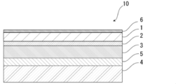
- FIG. 1 is a schematic diagram showing an example of a cross-sectional structure of an exterior material for an electricity storage device of the present disclosure
- FIG. BRIEF DESCRIPTION OF THE DRAWINGS FIG. 1 is a schematic diagram showing an example of a cross-sectional structure of an exterior material for an electricity storage device of the present disclosure
- 1 is a schematic diagram showing an example of a cross-sectional structure of an exterior material for an electricity storage device of the present disclosure
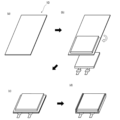
- FIG. FIG. 4 is a schematic diagram for explaining a method of housing an electricity storage device element in a package formed by the electricity storage device exterior material of the present disclosure. It is a schematic diagram for demonstrating the measuring method of heat-sealing strength. It is a schematic diagram for demonstrating the measuring method of heat-sealing strength.
- the exterior material for an electricity storage device of the present disclosure is composed of a laminate including at least a substrate layer, a barrier layer, and a heat-fusible resin layer in this order, and the fusion-bondable resin layer is measured using a differential scanning calorimeter.
- the DSC curve measured for has at least one melting peak temperature in the range of 115 ° C. or higher and 130 ° C.
- the heat-sealable resin of the exterior material for the power storage device It is characterized by having a Martens hardness of 8.5 MPa or more and 11.0 MPa or less, which is measured by pressing a Vickers indenter to a depth of 1 ⁇ m from the layer side surface in the thickness direction.
- the power storage device exterior material of the present disclosure has such a configuration, so that the power storage device elements can be suitably sealed until the temperature of the power storage device reaches a high temperature (for example, about 110 ° C.), and the gas generated inside the power storage device can be removed.
- the power storage device exterior material can be unsealed. Furthermore, since the Martens hardness of the heat-fusible resin layer 4 at 110° C. is set within this range, troubles during film formation of the heat-fusible resin layer 4 (specifically, high-temperature heat It is also possible to exhibit the effect that the problem that the fusible resin layer 4 adheres to the cooling roll (chill roll) and is difficult to peel off, thereby hindering the cooling process, does not easily occur.
- the exterior material for an electricity storage device of the present disclosure will be described in detail below.
- the numerical range indicated by “-” means “more than” and “less than”.
- the notation of 2 to 15 mm means 2 mm or more and 15 mm or less.
- the barrier layer 3 described later can usually be distinguished between MD (Machine Direction) and TD (Transverse Direction) in the manufacturing process.
- MD Machine Direction
- TD Transverse Direction
- the barrier layer 3 is made of a metal foil such as an aluminum alloy foil or a stainless steel foil
- the MD of the laminate usually matches the RD of the metal foil, so the surface of the metal foil of the laminate is observed to identify the rolling direction (RD) of the metal foil.
- the MD of the laminate can be specified.
- the TD of the laminate is perpendicular to the MD of the laminate, the TD of the laminate can also be specified.
- the MD of the exterior material for an electricity storage device cannot be specified due to the rolling marks of metal foil such as aluminum alloy foil or stainless steel foil, it can be specified by the following method.
- a method for confirming the MD of the exterior material for an electricity storage device there is a method for confirming the sea-island structure by observing the cross section of the heat-fusible resin layer of the exterior material for the electricity storage device with an electron microscope. In this method, the direction parallel to the cross section in which the average diameter of the island shape in the direction perpendicular to the thickness direction of the heat-fusible resin layer is maximum can be determined as the MD.
- the cross section in the length direction of the heat-fusible resin layer is changed by 10 degrees from a direction parallel to the cross section in the length direction, and the direction is perpendicular to the cross section in the length direction. (10 cross sections in total) are observed with electron micrographs to confirm the sea-island structure.
- the shape of each individual island is observed.
- the linear distance connecting the leftmost end in the direction perpendicular to the thickness direction of the heat-sealable resin layer and the rightmost end in the perpendicular direction is defined as the diameter y.
- the average of the top 20 diameters y of the island shape is calculated in descending order of diameter y.
- the direction parallel to the cross section in which the average diameter y of the island shape is the largest is determined as the MD.
- the electricity storage device exterior material 10 of the present disclosure includes, for example, as shown in FIGS. 4 in this order.
- the base material layer 1 is the outermost layer
- the heat-fusible resin layer 4 is the innermost layer.
- the heat-sealable resin layers 4 of the electricity storage device exterior material 10 face each other, and the peripheral edges are heat-sealed.
- the electricity storage device element is accommodated in the space formed by .
- the barrier layer 3 is the reference
- the heat-fusible resin layer 4 side is inner than the barrier layer 3
- the base layer 1 side is more than the barrier layer 3. outside.
- the electrical storage device exterior material 10 is provided between the base material layer 1 and the barrier layer 3 for the purpose of improving the adhesion between these layers, if necessary. It may have an adhesive layer 2 . Further, as shown in FIG. 3, an adhesive layer 5 is optionally provided between the barrier layer 3 and the heat-fusible resin layer 4 for the purpose of enhancing the adhesion between these layers. may Further, as shown in FIG. 3, a surface coating layer 6 or the like may be provided on the outside of the base material layer 1 (the side opposite to the heat-fusible resin layer 4 side), if necessary.
- the thickness of the laminate constituting the power storage device exterior material 10 is not particularly limited. Hereafter, about 120 micrometers or less are mentioned.
- the thickness of the laminate constituting the power storage device exterior material 10 is preferably about 35 ⁇ m or more, about 45 ⁇ m or more, about 60 ⁇ m or more can be mentioned.
- the preferred range of the laminate constituting the power storage device exterior material 10 is, for example, about 35 to 210 ⁇ m, about 35 to 190 ⁇ m, about 35 to 180 ⁇ m, about 35 to 155 ⁇ m, about 35 to 120 ⁇ m, and about 45 to 210 ⁇ m.
- the thickness (total thickness) of the laminate constituting the power storage device exterior material 10 is the base layer 1, the adhesive layer 2 provided as necessary, the barrier layer 3, if necessary
- the ratio of the total thickness of the adhesive layer 5, the heat-fusible resin layer 4, and the surface coating layer 6 provided as necessary is preferably 90% or more, more preferably 95% or more, More preferably, it is 98% or more.
- the electrical storage device exterior material 10 of the present disclosure includes the base material layer 1, the adhesive layer 2, the barrier layer 3, the adhesive layer 5, and the heat-fusible resin layer 4, the electrical storage device exterior
- the ratio of the total thickness of each layer to the thickness (total thickness) of the laminate constituting the material 10 is preferably 90% or more, more preferably 95% or more, and still more preferably 98% or more.
- the DSC curve measured for the heat-fusible resin layer 4 using a differential scanning calorimeter has at least one melting peak temperature in the range of 115 to 130°C.
- the electricity storage device element can be suitably sealed until the electricity storage device reaches a high temperature.
- the exterior material for an electricity storage device can be unsealed at a temperature at which gas generated inside the electricity storage device is desired to be released.
- the melting peak temperature is preferably about 119°C or higher, more preferably about 120°C or higher, even more preferably about 121°C or higher, and even more preferably 122°C. Above, more preferably 125° C. or higher, and preferably about 128° C. or lower. Preferred ranges of the melting peak temperature are about 115 to 128°C, about 119 to 130°C, about 119 to 128°C, about 120 to 130°C, about 120 to 128°C, about 121 to 130°C, and 121 to 128°C.
- the number of melting peak temperatures may be one or plural.
- the DSC curve of the heat-fusible resin layer 4 may have a melting peak temperature in the range of 115 to 130° C., and may have a further melting peak temperature outside this range. From the viewpoint of exhibiting the effects of the invention of the present disclosure more preferably, all of the melting peak temperatures of the DSC curve of the heat-fusible resin layer 4 are preferably 145° C. or less, and particularly preferably all within the above range. .
- the method for measuring the melting peak temperature is as follows.
- a heat-fusible resin layer is obtained from the exterior material for an electricity storage device and used as a measurement sample.
- the melting peak temperature of the DSC curve measured in accordance with the provisions of JIS K7121: 1987 and JIS K7121: 2012 (plastic transition temperature measurement method (JIS K7121: 2012 is JIS K7121: 1987 supplement 1)) to confirm.
- Measurements are performed using a differential scanning calorimeter (DSC, for example Differential Scanning Calorimeter Q200 from TA Instruments).
- the power storage device exterior material 10 of the present disclosure is based on the indentation method, at a measurement temperature (sample temperature) of 110 ° C., from the surface of the heat-fusible resin layer 4 side of the power storage device exterior material 10 of the present disclosure
- the Martens hardness is 8.5 to 11.0 MPa, which is measured by pressing a Vickers indenter to a depth of 1 ⁇ m in the thickness direction.
- the Martens hardness is preferably 9.0 MPa or more, more preferably 9.5 MPa or more, from the viewpoint of more suitably exhibiting the effects of the invention of the present disclosure. From the same point of view, the Martens hardness is preferably 10.9 MPa or less, more preferably 10.5 MPa or less.
- Preferred ranges of the Martens hardness are about 8.5 to 10.9 MPa, about 8.5 to 10.5 MPa, about 9.0 to 11.0 MPa, about 9.0 to 10.9 MPa, 9.0 to about 10.5 MPa, about 9.5 to 11.0 MPa, about 9.5 to 10.9 MPa, and about 9.5 to 10.5 MPa.
- the heat-fusible resin layer is difficult to move, and unexpected It is possible to prevent unsealing due to temperature, and for example, it is possible to suitably prevent the exterior material for an electric storage device from being unsealed due to gas generated by heating in the baking process in the manufacturing process of the electric storage device.
- the Martens hardness at 110° C. is within the above range, the exterior material for an electricity storage device can be opened before the internal pressure continues to rise due to the generation of gas from the electricity storage device due to heat.
- the Martens hardness of the heat-fusible resin layer 4 at 110°C is set within this range, troubles during film formation of the heat-fusible resin layer 4 (specifically, high-temperature heat It is also possible to exhibit the effect that the problem that the fusible resin layer 4 adheres closely to the cooling roll (chill roll) and is difficult to peel off, which hinders the cooling process, does not easily occur.
- the method for measuring the Martens hardness is as follows.
- a Vickers indenter is pushed in the thickness direction from the surface of the heat-fusible resin layer side of the exterior material for an electric storage device to a depth of 1 ⁇ m to measure the Martens hardness. do.
- the measurement conditions are as follows. Martens hardness is calculated from the load-displacement curve obtained by indentation with a Vickers indenter. As the measured value, the average obtained for 10 points on the surface of the heat-fusible resin layer is used.
- the Martens hardness is obtained by calculating the surface area A (mm 2 ) of the indenter at the maximum indentation depth of the Vickers indenter and dividing the maximum load F (N) by the surface area A (mm 2 ) (F/A).
- a measuring device for example, PicoDenter HM-500 manufactured by Fisher Instruments is used.
- PicoDenter HM-500 manufactured by Fisher Instruments is used.
- the exterior material for an electricity storage device is adhered so that the heat-fusible resin layer is on the opposite side of the glass slide to obtain a measurement sample.
- a heating stage is installed in an ultra-micro hardness tester equipped with a Vickers indenter, the stage temperature is set to 120° C., and the sample is heated for 5 minutes.
- the surface hardness of the surface of the measurement sample on the heat-fusible resin layer side is measured. The measured value of the surface hardness is rounded off to the third decimal place to make it equal to two decimal places.
- the Martens hardness of the heat-fusible resin layer at 110°C can be adjusted by the type of resin, temperature conditions during film formation, and the like. For example, when the temperature at which the heat-fusible resin layer 4 is formed increases, the resin decomposes and the Martens hardness of the heat-fusible resin layer 4 at 110° C. tends to decrease. When the film-forming temperature is lowered, the decomposition of the resin is suppressed and the Martens hardness at 110° C. of the heat-fusible resin layer tends to increase.
- the heat seal strength of the exterior material for an electricity storage device of the present disclosure when the measurement temperature is 25 ° C. is preferably about It is 70 N/15 mm or more, more preferably about 80 N/15 mm or more, and even more preferably about 90 N/15 mm or more. From the same point of view, the heat seal strength is preferably about 150 N/15 mm or less, more preferably about 140 N/15 mm or less, even more preferably about 130 N/15 mm or less.
- Preferred ranges of the heat seal strength are about 70 to 150 N/15 mm, about 70 to 140 N/15 mm, about 70 to 130 N/15 mm, about 80 to 150 N/15 mm, about 80 to 140 N/15 mm, and 80 to 130 N/15 mm. about 90 to 150 N/15 mm, about 90 to 140 N/15 mm, and about 90 to 130 N/15 mm.
- the heat seal strength of the power storage device exterior material of the present disclosure when the measurement temperature is 100 ° C. is preferably about It is 50 N/15 mm or more, more preferably about 60 N/15 mm or more, and even more preferably about 70 N/15 mm or more. Also, from the same point of view, the heat seal strength is preferably about 100 N/15 mm or less, more preferably about 90 N/15 mm or less.
- Preferred ranges of the heat seal strength are about 50 to 100 N/15 mm, about 50 to 90 N/15 mm, about 60 to 100 N/15 mm, about 60 to 90 N/15 mm, about 70 to 100 N/15 mm, and 70 to 90 N/15 mm. degree.
- the heat seal strength of the exterior material for an electricity storage device of the present disclosure when the measurement temperature is 110 ° C. is preferably is about 35 N/15 mm or greater, more preferably about 40 N/15 mm or greater, and even more preferably about 50 N/15 mm or greater.
- the heat seal strength is preferably about 80 N/15 mm or less, more preferably about 75 N/15 mm or less, even more preferably about 70 N/15 mm or less.
- Preferred ranges of the heat seal strength are about 35 to 80 N/15 mm, about 35 to 75 N/15 mm, about 35 to 70 N/15 mm, about 40 to 80 N/15 mm, about 40 to 75 N/15 mm, and 40 to 70 N/15 mm. about 50 to 80 N/15 mm, about 50 to 75 N/15 mm, and about 50 to 70 N/15 mm.
- the heat seal strength of the exterior material for an electricity storage device of the present disclosure when the measurement temperature is 120 ° C. is preferably is about 20 N/15 mm or less, more preferably about 10 N/15 mm or less.
- polypropylene easily decomposes when heat such as shear heat is applied. It has been found that polypropylene with advanced decomposition causes a rapid decrease in heat seal strength at high temperatures (for example, 100° C. or higher).
- the opening phenomenon of the electricity storage device can be explained by the heat seal strength of the exterior material for the electricity storage device at each temperature. It is desirable to have seal strength (for example, heat seal strength at 110° C. or less, such as 25° C., 100° C., 110° C.).
- seal strength of the power storage device exterior material at 120 ° C. is 20 N / 15 mm or less. is desirable.
- the method for measuring the heat seal strength is as follows.
- JIS K7127 Measure the heat seal strength at each measurement temperature (sample temperature) (for example, 25 ° C., 100 ° C., 110 ° C., 120 ° C., respectively.
- sample temperature for example, 25 ° C., 100 ° C., 110 ° C., 120 ° C., respectively.
- TD Prepare an electricity storage device exterior material cut into strips having a width of 15 mm in the direction.Specifically, as shown in FIG. direction) (Fig. 5a) Next, with the heat-fusible resin layers facing each other, the power storage device exterior material is cut in the MD direction at the position of the fold line P (middle in the MD direction). Fold in two (Fig.
- the measurement sample 13 is left at each measurement temperature for 2 minutes, and is subjected to a tensile tester (for example, Shimadzu Corporation, AG -Xplus (trade name)) at a speed of 300 mm/min (Fig. 6).
- a tensile tester for example, Shimadzu Corporation, AG -Xplus (trade name)
- the heat seal strength (N/ 15 mm), and the chuck-to-chuck distance is 50 mm.
- each layer forming the exterior material for the electricity storage device [base layer 1]
- the base material layer 1 is a layer provided for the purpose of exhibiting a function as a base material of an exterior material for an electric storage device.
- the base material layer 1 is located on the outer layer side of the exterior material for electrical storage devices.
- the material forming the base material layer 1 is not particularly limited as long as it functions as a base material, that is, at least has insulating properties.
- the base material layer 1 can be formed using, for example, a resin, and the resin may contain additives described later.
- the base material layer 1 can be made of, for example, a resin film.
- the base material layer 1 is formed of a resin film
- the resin forming the base material layer 1 may be formed into a film on the surface of the barrier layer 3 or the like by extrusion molding or coating to form the base material layer 1 formed of a resin film.
- the resin film may be an unstretched film or a stretched film. Examples of stretched films include uniaxially stretched films and biaxially stretched films, with biaxially stretched films being preferred. Examples of stretching methods for forming a biaxially stretched film include successive biaxial stretching, inflation, and simultaneous biaxial stretching. Methods for applying the resin include a roll coating method, a gravure coating method, an extrusion coating method, and the like.
- resins forming the base material layer 1 include resins such as polyester, polyamide, polyolefin, epoxy resin, acrylic resin, fluororesin, polyurethane, silicon resin, phenolic resin, and modified products of these resins. Further, the resin forming the base material layer 1 may be a copolymer of these resins or a modified product of the copolymer. Furthermore, it may be a mixture of these resins.
- the base material layer 1 preferably contains these resins as a main component, and more preferably contains polyester or polyamide as a main component.
- the main component is, among the resin components contained in the base layer 1, a content of, for example, 50% by mass or more, preferably 60% by mass or more, more preferably 70% by mass or more, and still more preferably 80% by mass. % or more, more preferably 90 mass % or more, more preferably 95 mass % or more, still more preferably 98 mass % or more, still more preferably 99 mass % or more.
- the base layer 1 containing polyester or polyamide as a main component means that the content of polyester or polyamide among the resin components contained in the base layer 1 is, for example, 50% by mass or more, preferably 60% by mass.
- % or more more preferably 70 mass % or more, still more preferably 80 mass % or more, still more preferably 90 mass % or more, still more preferably 95 mass % or more, still more preferably 98 mass % or more, still more preferably 99 mass % or more means that
- polyesters and polyamides are preferred as resins forming the base material layer 1 .
- polyester examples include polyethylene terephthalate, polybutylene terephthalate, polyethylene naphthalate, polybutylene naphthalate, polyethylene isophthalate, and copolymerized polyester.
- copolyester examples include copolyester having ethylene terephthalate as a main repeating unit.
- copolymer polyester polymerized with ethylene isophthalate with ethylene terephthalate as the main repeating unit hereinafter abbreviated after polyethylene (terephthalate / isophthalate)
- polyethylene (terephthalate / adipate) polyethylene (terephthalate / sodium sulfoisophthalate)
- polyethylene (terephthalate/sodium isophthalate) polyethylene (terephthalate/phenyl-dicarboxylate), polyethylene (terephthalate/decanedicarboxylate), and the like.
- These polyesters may be used singly or in combination of two or more.
- polyamide specifically, aliphatic polyamide such as nylon 6, nylon 66, nylon 610, nylon 12, nylon 46, copolymer of nylon 6 and nylon 66; terephthalic acid and / or isophthalic acid Hexamethylenediamine-isophthalic acid-terephthalic acid copolymer polyamide such as nylon 6I, nylon 6T, nylon 6IT, nylon 6I6T (I represents isophthalic acid, T represents terephthalic acid) containing structural units derived from, polyamide MXD6 (polymetallic Polyamides containing aromatics such as silylene adipamide); alicyclic polyamides such as polyamide PACM6 (polybis(4-aminocyclohexyl)methane adipamide); Copolymerized polyamides, polyesteramide copolymers and polyetheresteramide copolymers which are copolymers of copolymerized polyamides with polyesters or polyalkylene ether glycols; and polyamides such
- the substrate layer 1 preferably includes at least one of a polyester film, a polyamide film, and a polyolefin film, preferably includes at least one of an oriented polyester film, an oriented polyamide film, and an oriented polyolefin film, More preferably, at least one of an oriented polyethylene terephthalate film, an oriented polybutylene terephthalate film, an oriented nylon film, and an oriented polypropylene film is included, and a biaxially oriented polyethylene terephthalate film, a biaxially oriented polybutylene terephthalate film, and a biaxially oriented nylon film. , biaxially oriented polypropylene film.
- the base material layer 1 may be a single layer, or may be composed of two or more layers.
- the substrate layer 1 may be a laminate obtained by laminating resin films with an adhesive or the like, or may be formed by co-extrusion of resin to form two or more layers. It may be a laminate of resin films.
- a laminate of two or more resin films formed by coextrusion of resin may be used as the base material layer 1 without being stretched, or may be used as the base material layer 1 by being uniaxially or biaxially stretched.
- the laminate of two or more resin films in the substrate layer 1 include a laminate of a polyester film and a nylon film, a laminate of nylon films of two or more layers, and a laminate of polyester films of two or more layers. etc., preferably a laminate of a stretched nylon film and a stretched polyester film, a laminate of two or more layers of stretched nylon films, and a laminate of two or more layers of stretched polyester films.
- the substrate layer 1 is a laminate of two layers of resin films, a laminate of polyester resin films and polyester resin films, a laminate of polyamide resin films and polyamide resin films, or a laminate of polyester resin films and polyamide resin films.
- a laminate is preferred, and a laminate of polyethylene terephthalate film and polyethylene terephthalate film, a laminate of nylon film and nylon film, or a laminate of polyethylene terephthalate film and nylon film is more preferred.
- the polyester resin is resistant to discoloration when, for example, an electrolytic solution adheres to the surface. It is preferably located in the outermost layer.
- the two or more layers of resin films may be laminated via an adhesive.
- Preferred adhesives are the same as those exemplified for the adhesive layer 2 described later.
- the method for laminating two or more layers of resin films is not particularly limited, and known methods can be employed. Examples thereof include dry lamination, sandwich lamination, extrusion lamination, thermal lamination, and the like. A lamination method is mentioned.
- the thickness of the adhesive is, for example, about 2 to 5 ⁇ m.
- an anchor coat layer may be formed on the resin film and laminated. Examples of the anchor coat layer include the same adhesives as those exemplified for the adhesive layer 2 described later. At this time, the thickness of the anchor coat layer is, for example, about 0.01 to 1.0 ⁇ m.
- At least one of the surface and the inside of the substrate layer 1 may contain additives such as lubricants, flame retardants, antiblocking agents, antioxidants, light stabilizers, tackifiers, and antistatic agents. good. Only one type of additive may be used, or two or more types may be mixed and used.
- the surface and the inside of the base material layer 1 contains a lubricant.
- the lubricant is not particularly limited, but preferably includes an amide-based lubricant.
- Specific examples of amide lubricants include saturated fatty acid amides, unsaturated fatty acid amides, substituted amides, methylolamides, saturated fatty acid bisamides, unsaturated fatty acid bisamides, fatty acid ester amides, and aromatic bisamides.
- saturated fatty acid amides include lauric acid amide, palmitic acid amide, stearic acid amide, behenic acid amide, and hydroxystearic acid amide.
- unsaturated fatty acid amides include oleic acid amide and erucic acid amide.
- substituted amides include N-oleyl palmitic acid amide, N-stearyl stearic acid amide, N-stearyl oleic acid amide, N-oleyl stearic acid amide, N-stearyl erucic acid amide and the like.
- methylolamide include methylol stearamide.
- saturated fatty acid bisamides include methylenebisstearic acid amide, ethylenebiscapric acid amide, ethylenebislauric acid amide, ethylenebisstearic acid amide, ethylenebishydroxystearic acid amide, ethylenebisbehenic acid amide, hexamethylenebisstearin. acid amide, hexamethylenebisbehenamide, hexamethylenehydroxystearic acid amide, N,N'-distearyladipic acid amide, N,N'-distearylsebacic acid amide and the like.
- unsaturated fatty acid bisamides include ethylenebisoleic acid amide, ethylenebiserucic acid amide, hexamethylenebisoleic acid amide, N,N'-dioleyladipic acid amide, and N,N'-dioleylsebacic acid amide. etc.
- fatty acid ester amides include stearamide ethyl stearate.
- aromatic bisamide include m-xylylenebisstearic acid amide, m-xylylenebishydroxystearic acid amide, N,N'-distearyl isophthalic acid amide and the like.
- the lubricants may be used singly or in combination of two or more, preferably in combination of two or more.
- the amount of the lubricant is not particularly limited, but is, for example, about 3 mg/m 2 or more, preferably about 4 mg/m 2 or more, and about 5 mg/m 2 or more.
- the amount of lubricant present on the surface of the substrate layer 1 is, for example, about 15 mg/m 2 or less, preferably about 14 mg/m 2 or less, and about 10 mg/m 2 or less.
- the preferable range of the amount of the lubricant present on the surface of the substrate layer 1 is about 3 to 15 mg/m 2 , about 3 to 14 mg/m 2 , about 3 to 10 mg/m 2 , and about 4 to 15 mg/m 2 . , about 4 to 14 mg/m 2 , about 4 to 10 mg/m 2 , about 5 to 15 mg/m 2 , about 5 to 14 mg/m 2 , and about 5 to 10 mg/m 2 .
- the lubricant present on the surface of the substrate layer 1 may be obtained by exuding the lubricant contained in the resin constituting the substrate layer 1, or by coating the surface of the substrate layer 1 with the lubricant.
- the thickness of the base material layer 1 is not particularly limited as long as it functions as a base material.
- the thickness of the base layer 1 is, for example, about 50 ⁇ m or less, preferably about 35 ⁇ m or less, 11 ⁇ m or less, and 8 ⁇ m or less.
- the preferable range of the thickness of the base material layer 1 is about 3 to 50 ⁇ m, about 3 to 35 ⁇ m, about 3 to 11 ⁇ m, about 3 to 8 ⁇ m, about 10 to 50 ⁇ m, and about 10 to 35 ⁇ m. is preferably about 3 to 35 ⁇ m, about 3 to 11 ⁇ m, or about 3 to 8 ⁇ m, and about 35 to 50 ⁇ m is preferable for improving moldability.
- the thickness of the resin film constituting each layer is not particularly limited, but is, for example, about 2 ⁇ m or more, preferably about 10 ⁇ m or more, about 18 ⁇ m or greater.
- the thickness of the resin film forming each layer is, for example, about 33 ⁇ m or less, preferably about 28 ⁇ m or less, about 25 ⁇ m or less, about 23 ⁇ m or less, about 18 ⁇ m or less, 11 ⁇ m or less, and 8 ⁇ m or less.
- the preferred range of thickness of the resin film constituting each layer is about 2 to 33 ⁇ m, about 2 to 28 ⁇ m, about 2 to 25 ⁇ m, about 2 to 23 ⁇ m, about 2 to 18 ⁇ m, about 10 to 33 ⁇ m, 10 to About 28 ⁇ m, about 10 to 25 ⁇ m, about 10 to 23 ⁇ m, about 10 to 18 ⁇ m, about 18 to 33 ⁇ m, about 18 to 28 ⁇ m, about 18 to 25 ⁇ m, about 18 to 23 ⁇ m, about 2 to 11 ⁇ m, and about 2 to 8 ⁇ m. .
- the adhesive layer 2 is a layer provided between the base layer 1 and the barrier layer 3 as necessary for the purpose of enhancing the adhesiveness between them.
- the adhesive layer 2 is made of an adhesive that can bond the base material layer 1 and the barrier layer 3 together.
- the adhesive used to form the adhesive layer 2 is not limited, but may be any of a chemical reaction type, a solvent volatilization type, a hot melt type, a hot pressure type, and the like. Further, it may be a two-liquid curing adhesive (two-liquid adhesive), a one-liquid curing adhesive (one-liquid adhesive), or a resin that does not involve a curing reaction. Further, the adhesive layer 2 may be a single layer or multiple layers.
- the adhesive component contained in the adhesive include polyesters such as polyethylene terephthalate, polybutylene terephthalate, polyethylene naphthalate, polybutylene naphthalate, polyethylene isophthalate, and copolymerized polyester; polyether; polyurethane; epoxy resin; Phenolic resins; polyamides such as nylon 6, nylon 66, nylon 12, and copolymerized polyamides; polyolefin resins such as polyolefins, cyclic polyolefins, acid-modified polyolefins, and acid-modified cyclic polyolefins; polyvinyl acetate; cellulose; (meth)acrylic resins; polyimide; polycarbonate; amino resin such as urea resin and melamine resin; rubber such as chloroprene rubber, nitrile rubber and styrene-butadiene rubber; These adhesive components may be used singly or in combination of two or more.
- polyurethane adhesives are preferred.
- an appropriate curing agent can be used in combination with these adhesive component resins to increase the adhesive strength.
- the curing agent is selected from among polyisocyanates, polyfunctional epoxy resins, oxazoline group-containing polymers, polyamine resins, acid anhydrides, etc., depending on the functional groups of the adhesive component.
- polyurethane adhesives examples include polyurethane adhesives containing a first agent containing a polyol compound and a second agent containing an isocyanate compound.
- Preferred examples include a two-component curing type polyurethane adhesive comprising a polyol such as polyester polyol, polyether polyol, and acrylic polyol as the first agent and an aromatic or aliphatic polyisocyanate as the second agent.
- polyurethane adhesives include polyurethane adhesives containing an isocyanate compound and a polyurethane compound obtained by reacting a polyol compound and an isocyanate compound in advance.
- polyurethane adhesives examples include polyurethane adhesives containing a polyurethane compound obtained by reacting a polyol compound and an isocyanate compound in advance and a polyol compound.
- polyurethane adhesives examples include polyurethane adhesives obtained by reacting a polyurethane compound obtained by reacting a polyol compound and an isocyanate compound in advance with moisture in the air and then curing the compound.
- the polyol compound it is preferable to use a polyester polyol having a hydroxyl group in a side chain in addition to the terminal hydroxyl group of the repeating unit.
- the second agent examples include aliphatic, alicyclic, aromatic, and araliphatic isocyanate compounds.
- isocyanate compounds include hexamethylene diisocyanate (HDI), xylylene diisocyanate (XDI), isophorone diisocyanate (IPDI), hydrogenated XDI (H6XDI), hydrogenated MDI (H12MDI), tolylene diisocyanate (TDI), and diphenylmethane diisocyanate. (MDI), naphthalene diisocyanate (NDI), and the like.
- polyfunctional isocyanate-modified products of one or more of these diisocyanates are also included.
- a polymer for example, a trimer
- Such multimers include adducts, biurets, nurates and the like. Since the adhesive layer 2 is formed of a polyurethane adhesive, the exterior material for an electric storage device is imparted with excellent electrolyte resistance, and even if the electrolyte adheres to the side surface, the base layer 1 is suppressed from being peeled off. .
- the adhesive layer 2 may contain other components as long as they do not interfere with adhesion, and may contain colorants, thermoplastic elastomers, tackifiers, fillers, and the like. Since the adhesive layer 2 contains a coloring agent, the exterior material for an electric storage device can be colored. Known substances such as pigments and dyes can be used as the colorant. In addition, only one type of colorant may be used, or two or more types may be mixed and used.
- the type of pigment is not particularly limited as long as it does not impair the adhesiveness of the adhesive layer 2.
- organic pigments include azo-based, phthalocyanine-based, quinacridone-based, anthraquinone-based, dioxazine-based, indigothioindigo-based, perinone-perylene-based, isoindolenine-based, and benzimidazolone-based pigments.
- pigments include carbon black, titanium oxide, cadmium, lead, chromium oxide, and iron pigments, as well as fine mica powder and fish scale foil.
- carbon black is preferable, for example, in order to make the external appearance of the exterior material for a power storage device black.
- the average particle size of the pigment is not particularly limited, and is, for example, about 0.05 to 5 ⁇ m, preferably about 0.08 to 2 ⁇ m.
- the average particle size of the pigment is the median size measured with a laser diffraction/scattering particle size distribution analyzer.
- the content of the pigment in the adhesive layer 2 is not particularly limited as long as the power storage device exterior material is colored, and is, for example, about 5 to 60% by mass, preferably 10 to 40% by mass.
- the thickness of the adhesive layer 2 is not particularly limited as long as the substrate layer 1 and the barrier layer 3 can be adhered, but is, for example, about 1 ⁇ m or more, or about 2 ⁇ m or more. Also, the thickness of the adhesive layer 2 is, for example, about 10 ⁇ m or less, or about 5 ⁇ m or less. Moreover, the preferable range of the thickness of the adhesive layer 2 is about 1 to 10 ⁇ m, about 1 to 5 ⁇ m, about 2 to 10 ⁇ m, and about 2 to 5 ⁇ m.
- the colored layer is a layer provided as necessary between the base layer 1 and the barrier layer 3 (not shown).
- a colored layer may be provided between the base material layer 1 and the adhesive layer 2 and between the adhesive layer 2 and the barrier layer 3 . Further, a colored layer may be provided outside the base material layer 1 . By providing the colored layer, the exterior material for an electricity storage device can be colored.
- the colored layer can be formed, for example, by applying ink containing a coloring agent to the surface of the base material layer 1 or the surface of the barrier layer 3 .
- a coloring agent such as pigments and dyes can be used as the colorant.
- only one type of colorant may be used, or two or more types may be mixed and used.
- colorant contained in the colored layer are the same as those exemplified in the [Adhesive layer 2] column.
- the barrier layer 3 is a layer that at least prevents permeation of moisture.
- barrier layer 3 for example, a metal foil, a deposited film, a resin layer, etc., having barrier properties can be used.
- vapor-deposited films include metal vapor-deposited films, inorganic oxide vapor-deposited films, and carbon-containing inorganic oxide vapor-deposited films.
- the barrier layer 3 may also include a resin film provided with at least one of these deposited films and resin layers. A plurality of barrier layers 3 may be provided.
- the barrier layer 3 preferably includes a layer made of a metal material.
- the metal material that constitutes the barrier layer 3 include aluminum alloys, stainless steels, titanium steels, and steel plates. When used as metal foils, at least one of aluminum alloy foils and stainless steel foils is included. is preferred.
- the aluminum alloy foil is more preferably a soft aluminum alloy foil made of, for example, an annealed aluminum alloy from the viewpoint of improving the formability of the exterior material for an electric storage device, and from the viewpoint of further improving the formability. Therefore, it is preferably an aluminum alloy foil containing iron.
- the iron content is preferably 0.1 to 9.0% by mass, more preferably 0.5 to 2.0% by mass.
- the iron content is 0.1% by mass or more, it is possible to obtain an exterior material for an electricity storage device having superior moldability.
- the iron content is 9.0% by mass or less, it is possible to obtain an exterior material for an electricity storage device that is more excellent in flexibility.
- the soft aluminum alloy foil for example, an aluminum alloy having a composition specified by JIS H4160: 1994 A8021H-O, JIS H4160: 1994 A8079H-O, JIS H4000: 2014 A8021P-O, or JIS H4000: 2014 A8079P-O foil.
- silicon, magnesium, copper, manganese, etc. may be added as needed.
- softening can be performed by annealing treatment or the like.
- stainless steel foils include austenitic, ferritic, austenitic/ferritic, martensitic, and precipitation hardened stainless steel foils. Furthermore, from the viewpoint of providing an exterior material for an electricity storage device with excellent formability, the stainless steel foil is preferably made of austenitic stainless steel.
- austenitic stainless steel that constitutes the stainless steel foil
- SUS304 is particularly preferable.
- the thickness of the barrier layer 3 should be at least as long as it functions as a barrier layer that suppresses the intrusion of moisture.
- the thickness of the barrier layer 3 is preferably about 85 ⁇ m or less, more preferably about 50 ⁇ m or less, even more preferably about 40 ⁇ m or less, particularly preferably about 35 ⁇ m or less.
- the thickness of the barrier layer 3 is preferably about 10 ⁇ m or more, more preferably about 20 ⁇ m or more, and more preferably about 25 ⁇ m or more.
- the preferred range of thickness of the barrier layer 3 is about 10 to 85 ⁇ m, about 10 to 50 ⁇ m, about 10 to 40 ⁇ m, about 10 to 35 ⁇ m, about 20 to 85 ⁇ m, about 20 to 50 ⁇ m, about 20 to 40 ⁇ m, 20 to 40 ⁇ m. About 35 ⁇ m, about 25 to 85 ⁇ m, about 25 to 50 ⁇ m, about 25 to 40 ⁇ m, and about 25 to 35 ⁇ m.
- the barrier layer 3 is made of an aluminum alloy foil, the above range is particularly preferred.
- the thickness of the barrier layer 3 is preferably about 45 ⁇ m or more from the viewpoint of imparting high moldability and high rigidity to the power storage device exterior material 10.
- the high moldability of the electrical storage device exterior material 10 facilitates deep drawing, which can contribute to increasing the capacity of the electrical storage device.
- the thickness of the stainless steel foil is preferably about 60 ⁇ m or less, more preferably about 50 ⁇ m or less, even more preferably about 40 ⁇ m or less, and even more preferably about 30 ⁇ m. Below, it is particularly preferably about 25 ⁇ m or less. Also, the thickness of the stainless steel foil is preferably about 10 ⁇ m or more, more preferably about 15 ⁇ m or more.
- the preferable range of the thickness of the stainless steel foil is about 10 to 60 ⁇ m, about 10 to 50 ⁇ m, about 10 to 40 ⁇ m, about 10 to 30 ⁇ m, about 10 to 25 ⁇ m, about 15 to 60 ⁇ m, about 15 to 50 ⁇ m, 15 to 50 ⁇ m.
- About 40 ⁇ m, about 15 to 30 ⁇ m, and about 15 to 25 ⁇ m can be mentioned.
- the barrier layer 3 is a metal foil, it is preferable that at least the surface opposite to the base layer is provided with a corrosion-resistant film in order to prevent dissolution and corrosion.
- the barrier layer 3 may be provided with a corrosion resistant coating on both sides.
- the corrosion-resistant film includes, for example, hydrothermal transformation treatment such as boehmite treatment, chemical conversion treatment, anodizing treatment, plating treatment such as nickel and chromium, and corrosion prevention treatment such as applying a coating agent to the surface of the barrier layer. It is a thin film that provides corrosion resistance (for example, acid resistance, alkali resistance, etc.) to the barrier layer.
- the corrosion-resistant film specifically means a film that improves the acid resistance of the barrier layer (acid-resistant film), a film that improves the alkali resistance of the barrier layer (alkali-resistant film), and the like.
- the treatment for forming the corrosion-resistant film one type may be performed, or two or more types may be used in combination. Also, not only one layer but also multiple layers can be used.
- the hydrothermal transformation treatment and the anodizing treatment are treatments in which the surface of the metal foil is dissolved with a treating agent to form a metal compound having excellent corrosion resistance. These treatments are sometimes included in the definition of chemical conversion treatment.
- the barrier layer 3 includes the corrosion-resistant film.
- the corrosion-resistant coating prevents delamination between the barrier layer (e.g., aluminum alloy foil) and the substrate layer during the molding of the exterior material for power storage devices, and the hydrogen fluoride generated by the reaction between the electrolyte and moisture. , the dissolution and corrosion of the barrier layer surface, especially when the barrier layer is an aluminum alloy foil, the aluminum oxide present on the barrier layer surface is prevented from dissolving and corroding, and the adhesion (wettability) of the barrier layer surface is improved. , and exhibits the effect of preventing delamination between the base material layer and the barrier layer during heat sealing and preventing delamination between the base material layer and the barrier layer during molding.
- the barrier layer e.g., aluminum alloy foil
- corrosion-resistant coatings formed by chemical conversion treatment are known, and are mainly composed of at least one of phosphates, chromates, fluorides, triazinethiol compounds, and rare earth oxides. and corrosion-resistant coatings containing.
- Examples of chemical conversion treatments using phosphate and chromate include chromic acid chromate treatment, phosphoric acid chromate treatment, phosphoric acid-chromate treatment, and chromate treatment.
- Examples of compounds include chromium nitrate, chromium fluoride, chromium sulfate, chromium acetate, chromium oxalate, chromium biphosphate, chromium acetyl acetate, chromium chloride, potassium chromium sulfate, and the like.
- Phosphorus compounds used for these treatments include sodium phosphate, potassium phosphate, ammonium phosphate, polyphosphoric acid, and the like.
- Examples of the chromate treatment include etching chromate treatment, electrolytic chromate treatment, coating-type chromate treatment, etc., and coating-type chromate treatment is preferred.
- the inner layer side surface of the barrier layer (for example, aluminum alloy foil) is first subjected to a well-known method such as an alkali immersion method, an electrolytic cleaning method, an acid cleaning method, an electrolytic acid cleaning method, an acid activation method, or the like.
- metal phosphate such as Cr (chromium) phosphate, Ti (titanium) phosphate, Zr (zirconium) phosphate, Zn (zinc) phosphate is applied to the degreased surface.
- a processing solution mainly composed of a salt and a mixture of these metal salts a processing solution mainly composed of a non-metal phosphate salt and a mixture of these non-metal salts, or a mixture of these and a synthetic resin.
- This is a treatment in which a treatment liquid composed of a mixture is applied by a well-known coating method such as a roll coating method, a gravure printing method, or an immersion method, and then dried.
- Various solvents such as water, alcohol-based solvents, hydrocarbon-based solvents, ketone-based solvents, ester-based solvents, and ether-based solvents can be used as the treatment liquid, and water is preferred.
- the resin component used at this time includes polymers such as phenolic resins and acrylic resins. and the chromate treatment used.
- the repeating units represented by the following general formulas (1) to (4) may be contained singly or in any combination of two or more. good too.
- the acrylic resin is polyacrylic acid, acrylic acid methacrylic acid ester copolymer, acrylic acid maleic acid copolymer, acrylic acid styrene copolymer, or derivatives thereof such as sodium salts, ammonium salts, and amine salts. is preferred.
- derivatives of polyacrylic acid such as ammonium salt, sodium salt or amine salt of polyacrylic acid are preferred.
- polyacrylic acid means a polymer of acrylic acid.
- the acrylic resin is preferably a copolymer of acrylic acid and dicarboxylic acid or dicarboxylic anhydride, and the ammonium salt, sodium salt, Alternatively, it is also preferably an amine salt. Only one type of acrylic resin may be used, or two or more types may be mixed and used.
- X represents a hydrogen atom, hydroxy group, alkyl group, hydroxyalkyl group, allyl group or benzyl group.
- R 1 and R 2 are the same or different and represent a hydroxy group, an alkyl group or a hydroxyalkyl group.
- alkyl groups represented by X, R 1 and R 2 in general formulas (1) to (4) include methyl group, ethyl group, n-propyl group, isopropyl group, n-butyl group, isobutyl group, A linear or branched alkyl group having 1 to 4 carbon atoms such as a tert-butyl group can be mentioned.
- hydroxyalkyl groups represented by X, R 1 and R 2 include hydroxymethyl group, 1-hydroxyethyl group, 2-hydroxyethyl group, 1-hydroxypropyl group, 2-hydroxypropyl group, 3- A straight or branched chain having 1 to 4 carbon atoms substituted with one hydroxy group such as hydroxypropyl group, 1-hydroxybutyl group, 2-hydroxybutyl group, 3-hydroxybutyl group and 4-hydroxybutyl group An alkyl group is mentioned.
- the alkyl groups and hydroxyalkyl groups represented by X, R 1 and R 2 may be the same or different.
- X is preferably a hydrogen atom, a hydroxy group or a hydroxyalkyl group.
- the number average molecular weight of the aminated phenol polymer having repeating units represented by formulas (1) to (4) is, for example, preferably about 500 to 1,000,000, more preferably about 1,000 to 20,000. more preferred.
- the aminated phenol polymer is produced, for example, by polycondensing a phenol compound or naphthol compound and formaldehyde to produce a polymer comprising repeating units represented by the general formula (1) or general formula (3), followed by formaldehyde. and an amine (R 1 R 2 NH) to introduce a functional group (--CH 2 NR 1 R 2 ) into the polymer obtained above.
- An aminated phenol polymer is used individually by 1 type or in mixture of 2 or more types.
- the corrosion-resistant film is formed by a coating-type corrosion prevention treatment in which a coating agent containing at least one selected from the group consisting of rare earth element oxide sol, anionic polymer, and cationic polymer is applied.
- a thin film that is The coating agent may further contain phosphoric acid or a phosphate, a cross-linking agent for cross-linking the polymer.
- rare earth element oxide sol rare earth element oxide fine particles (for example, particles having an average particle size of 100 nm or less) are dispersed in a liquid dispersion medium.
- rare earth element oxides include cerium oxide, yttrium oxide, neodymium oxide, and lanthanum oxide, and cerium oxide is preferable from the viewpoint of further improving adhesion.
- the rare earth element oxides contained in the corrosion-resistant coating can be used singly or in combination of two or more.
- various solvents such as water, alcohol solvents, hydrocarbon solvents, ketone solvents, ester solvents, and ether solvents can be used, with water being preferred.
- the cationic polymer include polyethyleneimine, an ionic polymer complex composed of a polymer containing polyethyleneimine and carboxylic acid, a primary amine-grafted acrylic resin obtained by graft-polymerizing a primary amine to an acrylic backbone, polyallylamine, or a derivative thereof. , aminated phenols and the like are preferred.
- the anionic polymer is preferably poly(meth)acrylic acid or a salt thereof, or a copolymer containing (meth)acrylic acid or a salt thereof as a main component.
- the cross-linking agent is preferably at least one selected from the group consisting of a compound having a functional group such as an isocyanate group, a glycidyl group, a carboxyl group, or an oxazoline group, and a silane coupling agent.
- the phosphoric acid or phosphate is preferably condensed phosphoric acid or condensed phosphate.
- fine particles of metal oxides such as aluminum oxide, titanium oxide, cerium oxide, and tin oxide, and barium sulfate are dispersed in phosphoric acid, which is applied to the surface of the barrier layer. C. or more, and those formed by performing baking processing are mentioned.
- the corrosion-resistant film may, if necessary, have a laminated structure in which at least one of a cationic polymer and an anionic polymer is further laminated.
- a cationic polymer and anionic polymers include those described above.
- the analysis of the composition of the corrosion-resistant coating can be performed using, for example, time-of-flight secondary ion mass spectrometry.
- the amount of the corrosion-resistant film formed on the surface of the barrier layer 3 in the chemical conversion treatment is not particularly limited. is about 0.5 to 50 mg, preferably about 1.0 to 40 mg in terms of chromium, the phosphorus compound is about 0.5 to 50 mg, preferably about 1.0 to 40 mg in terms of phosphorus, and aminated phenol polymer is contained in a ratio of, for example, about 1.0 to 200 mg, preferably about 5.0 to 150 mg.
- the thickness of the corrosion-resistant coating is not particularly limited, but is preferably about 1 nm to 20 ⁇ m, more preferably 1 nm to 100 nm, from the viewpoint of cohesion of the coating and adhesion to the barrier layer and the heat-sealable resin layer. about 1 nm to 50 nm, more preferably about 1 nm to 50 nm.
- the thickness of the corrosion-resistant film can be measured by observation with a transmission electron microscope, or by a combination of observation with a transmission electron microscope and energy dispersive X-ray spectroscopy or electron beam energy loss spectroscopy.
- secondary ions composed of Ce, P and O for example, at least one of Ce 2 PO 4 + and CePO 4 ⁇ species
- secondary ions composed of Cr, P, and O eg, at least one of CrPO 2 + and CrPO 4 ⁇
- Chemical conversion treatment involves applying a solution containing a compound used to form a corrosion-resistant film to the surface of the barrier layer by a bar coating method, roll coating method, gravure coating method, immersion method, or the like. is carried out by heating so that the temperature is about 70 to 200°C.
- the barrier layer may be previously subjected to a degreasing treatment by an alkali immersion method, an electrolytic cleaning method, an acid cleaning method, an electrolytic acid cleaning method, or the like. By performing the degreasing treatment in this way, it becomes possible to perform the chemical conversion treatment on the surface of the barrier layer more efficiently.
- an acid degreasing agent obtained by dissolving a fluorine-containing compound in an inorganic acid for degreasing treatment it is possible to form not only the degreasing effect of the metal foil but also the passive metal fluoride. In such cases, only degreasing treatment may be performed.
- the heat-fusible resin layer 4 corresponds to the innermost layer, and has the function of sealing the power storage device element by heat-sealing the heat-fusible resin layers to each other when assembling the power storage device. It is a layer (sealant layer) that exhibits
- the electrical storage device exterior material of the present disclosure has a DSC curve measured for the heat-fusible resin layer 4 using a differential scanning calorimeter. has at least one melting peak temperature in the range of 115-130°C. The detailed explanation of the melting peak temperature in the DSC curve of the heat-fusible resin layer 4 is as described above.
- the resin constituting the heat-fusible resin layer 4 is not particularly limited as long as it is heat-fusible, but resins containing polyolefin skeletons such as polyolefins and acid-modified polyolefins are preferable.
- the inclusion of a polyolefin skeleton in the resin constituting the heat-fusible resin layer 4 can be analyzed by, for example, infrared spectroscopy, gas chromatography-mass spectrometry, or the like. Further, when the resin constituting the heat-fusible resin layer 4 is analyzed by infrared spectroscopy, it is preferable that a peak derived from maleic anhydride is detected.
- peaks derived from maleic anhydride are detected near wavenumbers of 1760 cm ⁇ 1 and 1780 cm ⁇ 1 .
- the heat-sealable resin layer 4 is a layer composed of maleic anhydride-modified polyolefin
- a peak derived from maleic anhydride is detected when measured by infrared spectroscopy.
- the degree of acid denaturation is low, the peak may be too small to be detected. In that case, it can be analyzed by nuclear magnetic resonance spectroscopy.
- polyolefins include polyethylenes such as low-density polyethylene, medium-density polyethylene, high-density polyethylene, and linear low-density polyethylene; ethylene- ⁇ -olefin copolymers; block copolymers of ethylene), random copolymers of polypropylene (for example, random copolymers of propylene and ethylene); propylene- ⁇ -olefin copolymers; ethylene-butene-propylene terpolymers; Among these, polypropylene is preferred.
- the polyolefin resin is a copolymer, it may be a block copolymer or a random copolymer. These polyolefin-based resins may be used alone or in combination of two or more.
- the polyolefin may be a cyclic polyolefin.
- a cyclic polyolefin is a copolymer of an olefin and a cyclic monomer.
- the olefin which is a constituent monomer of the cyclic polyolefin, include ethylene, propylene, 4-methyl-1-pentene, styrene, butadiene, and isoprene. be done.
- Examples of cyclic monomers constituting cyclic polyolefins include cyclic alkenes such as norbornene; cyclic dienes such as cyclopentadiene, dicyclopentadiene, cyclohexadiene and norbornadiene. Among these, cyclic alkenes are preferred, and norbornene is more preferred.
- Acid-modified polyolefin is a polymer modified by block polymerization or graft polymerization of polyolefin with an acid component.
- polyolefins to be acid-modified the above polyolefins, copolymers obtained by copolymerizing the above polyolefins with polar molecules such as acrylic acid or methacrylic acid, or polymers such as crosslinked polyolefins can be used.
- acid components used for acid modification include carboxylic acids such as maleic acid, acrylic acid, itaconic acid, crotonic acid, maleic anhydride, itaconic anhydride, and anhydrides thereof.
- the acid-modified polyolefin may be an acid-modified cyclic polyolefin.
- Acid-modified cyclic polyolefin is a polymer obtained by copolymerizing a part of the monomers constituting the cyclic polyolefin in place of the acid component, or by block-polymerizing or graft-polymerizing the acid component to the cyclic polyolefin. be.
- the acid-modified cyclic polyolefin is the same as described above.
- the acid component used for acid modification is the same as the acid component used for modification of polyolefin.
- Preferable acid-modified polyolefins include polyolefins modified with carboxylic acid or its anhydride, polypropylene modified with carboxylic acid or its anhydride, maleic anhydride-modified polyolefin, and maleic anhydride-modified polypropylene.
- the heat-fusible resin layer 4 may be formed of one type of resin alone, or may be formed of a blend polymer in which two or more types of resin are combined. Although it is preferable to use a resin with a low MFR for the heat-fusible resin layer 4 in consideration of the stability of the film forming process and the insulating properties, the resin with a low MFR is likely to be sheared during processing and thermally decomposed. Therefore, physical properties tend to be unstable. On the other hand, when a resin having a high MFR is used for the heat-fusible resin layer 4, it is less likely to be sheared during processing, so that heat generation is less likely to occur and thermal decomposition is less likely to occur.
- the exterior material for the electricity storage device can be maintained until the temperature of the electricity storage device reaches a high temperature (for example, about 110° C.) while maintaining insulation. and at a temperature (for example, about 120° C.) at which it is desired to release the gas generated inside the electricity storage device, the electricity storage device exterior material can be adjusted so that the electricity storage device exterior material is unsealed.
- the heat-fusible resin layer 4 may be formed of only one layer, or may be formed of two or more layers of the same or different resins.
- the heat-fusible resin layer 4 may contain a lubricant or the like as necessary.
- a lubricant is not particularly limited, and known lubricants can be used. Lubricants may be used singly or in combination of two or more.
- the lubricant is not particularly limited, but preferably includes an amide-based lubricant. Specific examples of the lubricant include those exemplified for the base material layer 1 .
- the lubricants may be used singly or in combination of two or more, preferably in combination of two or more.
- the surface and the inside of the heat-fusible resin layer 4 contains a lubricant.
- the lubricant is not particularly limited, but preferably includes an amide-based lubricant.
- Specific examples of amide lubricants include saturated fatty acid amides, unsaturated fatty acid amides, substituted amides, methylolamides, saturated fatty acid bisamides, unsaturated fatty acid bisamides, fatty acid ester amides, and aromatic bisamides.
- saturated fatty acid amides include lauric acid amide, palmitic acid amide, stearic acid amide, behenic acid amide, and hydroxystearic acid amide.
- unsaturated fatty acid amides include oleic acid amide and erucic acid amide.
- substituted amides include N-oleyl palmitic acid amide, N-stearyl stearic acid amide, N-stearyl oleic acid amide, N-oleyl stearic acid amide, N-stearyl erucic acid amide and the like.
- methylolamide include methylol stearamide.
- saturated fatty acid bisamides include methylenebisstearic acid amide, ethylenebiscapric acid amide, ethylenebislauric acid amide, ethylenebisstearic acid amide, ethylenebishydroxystearic acid amide, ethylenebisbehenic acid amide, hexamethylenebisstearin. acid amide, hexamethylenebisbehenamide, hexamethylenehydroxystearic acid amide, N,N'-distearyladipic acid amide, N,N'-distearylsebacic acid amide and the like.
- unsaturated fatty acid bisamides include ethylenebisoleic acid amide, ethylenebiserucic acid amide, hexamethylenebisoleic acid amide, N,N'-dioleyladipic acid amide, and N,N'-dioleylsebacic acid amide. etc.
- fatty acid ester amides include stearamide ethyl stearate.
- aromatic bisamide include m-xylylenebisstearic acid amide, m-xylylenebishydroxystearic acid amide, N,N'-distearyl isophthalic acid amide and the like.
- the lubricants may be used singly or in combination of two or more, preferably in combination of two or more.
- the amount of the lubricant is not particularly limited, but from the viewpoint of improving the moldability of the exterior material for an electricity storage device, it is preferably about 1 mg/m 2 or more, More preferably about 3 mg/m 2 or more, still more preferably about 5 mg/m 2 or more, still more preferably about 10 mg/m 2 or more, still more preferably about 15 mg/m 2 or more, and more preferably about 50 mg/m 2 or more 2 or less, more preferably about 40 mg/m 2 or less.
- Preferred ranges are about 1 to 50 mg/m 2 , about 1 to 40 mg/m 2 , about 3 to 50 mg/m 2 , and 3 to 40 mg/m 2 . about 5 to 50 mg/m 2 , about 5 to 40 mg/m 2 , about 10 to 50 mg/m 2 , about 10 to 40 mg/m 2 , about 15 to 50 mg/m 2 , about 15 to 40 mg/m 2 mentioned.
- the amount of the lubricant is not particularly limited, but from the viewpoint of improving the moldability of the exterior material for an electricity storage device, it is preferably about 100 ppm or more, more preferably about 100 ppm or more.
- about 300 ppm or more, more preferably about 500 ppm or more, preferably about 3000 ppm or less, more preferably about 2000 ppm or less, preferably about 100 to 3000 ppm, about 100 to 2000 ppm, about 300 to 3000 ppm, About 300 to 2000 ppm, about 500 to 3000 ppm, and about 500 to 2000 ppm can be mentioned.
- the above lubricant amount is the total lubricant amount.
- the amount of the first type of lubricant is not particularly limited. It is preferably about 100 ppm or more, more preferably about 300 ppm or more, still more preferably about 500 ppm or more, and preferably about 3000 ppm or less, more preferably about 2000 ppm or less. about 2000 ppm, about 300 to 3000 ppm, about 300 to 2000 ppm, about 500 to 3000 ppm, and about 500 to 2000 ppm.
- the amount of the second type of lubricant is not particularly limited, but from the viewpoint of improving the moldability of the exterior material for an electric storage device, it is preferably about 50 ppm or more, more preferably about 100 ppm or more, and still more preferably about 200 ppm or more. , Also preferably about 1500 ppm or less, more preferably about 1000 ppm or less. About 1000 ppm is mentioned.
- the lubricant present on the surface of the heat-fusible resin layer 4 may be obtained by exuding the lubricant contained in the resin constituting the heat-fusible resin layer 4 .
- the surface may be coated with a lubricant.
- the thickness of the heat-fusible resin layer 4 is not particularly limited as long as the heat-fusible resin layers are heat-sealed to each other to exhibit the function of sealing the electricity storage device element. About 85 ⁇ m or less, more preferably about 15 to 85 ⁇ m. For example, when the thickness of the adhesive layer 5 described later is 10 ⁇ m or more, the thickness of the heat-fusible resin layer 4 is preferably about 85 ⁇ m or less, more preferably about 15 to 45 ⁇ m. When the thickness of the adhesive layer 5 described later is less than 10 ⁇ m or when the adhesive layer 5 is not provided, the thickness of the heat-fusible resin layer 4 is preferably about 20 ⁇ m or more, more preferably 35 to 85 ⁇ m. degree.
- the adhesive layer 5 is provided between the barrier layer 3 (or the corrosion-resistant film) and the heat-fusible resin layer 4 as necessary in order to firmly bond them. layer to be provided.
- the melting peak temperature observed in the adhesive layer 5 is preferably about 120° C. or higher, more preferably about 130° C. or higher, more preferably about 140° C. or higher, and further preferably about 140° C. or higher. It is preferably about 150° C. or higher, more preferably about 170° C. or lower, more preferably 150° C. or lower. About 170°C, about 130 to 150°C, about 140 to 170°C, about 140 to 150°C, and about 150 to 170°C. The number of melting peak temperatures may be one or plural. Also, the adhesive layer 5 may have a melting peak temperature outside the range of 120-170°C.
- the melting peak temperatures observed in the adhesive layer 5 are all preferably in the range of 120 to 170°C.
- the melting peak temperature is measured by the method described in the above section (Melting peak temperature), except that the adhesive layer is obtained from the power storage device exterior material and used as a measurement sample.
- the adhesive layer 5 is made of a resin that can bond the barrier layer 3 and the heat-fusible resin layer 4 together.
- a thermoplastic resin can be suitably used as the resin used to form the adhesive layer 5 .
- the resin used to form the adhesive layer 5 preferably contains a polyolefin skeleton, and includes the polyolefins and acid-modified polyolefins exemplified for the heat-sealable resin layer 4 described above.
- the adhesive layer 5 preferably contains an acid-modified polyolefin.
- Acid-modified components include dicarboxylic acids such as maleic acid, itaconic acid, succinic acid and adipic acid, their anhydrides, acrylic acid and methacrylic acid. Maleic acid is most preferred.
- the olefin component is preferably a polypropylene-based resin, and the adhesive layer 5 most preferably contains maleic anhydride-modified polypropylene.
- the adhesive layer 5 When the resin used to form the adhesive layer 5 contains a polyolefin skeleton, the adhesive layer 5 preferably contains a resin containing a polyolefin skeleton as a main component, and contains an acid-modified polyolefin as a main component. More preferably, it contains acid-modified polypropylene as a main component.
- the main component means that the resin component contained in the adhesive layer 5 has a content of, for example, 50% by mass or more, preferably 60% by mass or more, more preferably 70% by mass or more, and further preferably 80% by mass.
- the adhesive layer 5 containing acid-modified polypropylene as a main component means that the content of acid-modified polypropylene among the resin components contained in the adhesive layer 5 is, for example, 50% by mass or more, preferably 60% by mass or more, or more. It is preferably 70% by mass or more, more preferably 80% by mass or more, still more preferably 90% by mass or more, still more preferably 95% by mass or more, still more preferably 98% by mass or more, further preferably 99% by mass or more. means.
- the resin constituting the adhesive layer 5 contains a polyolefin skeleton can be analyzed by, for example, infrared spectroscopy, gas chromatography mass spectrometry, or the like, and the analysis method is not particularly limited.
- the fact that the resin constituting the adhesive layer 5 contains an acid-modified polyolefin means that, for example, when the maleic anhydride-modified polyolefin is measured by infrared spectroscopy , anhydrous A peak derived from maleic acid is detected. However, if the degree of acid denaturation is low, the peak may be too small to be detected. In that case, it can be analyzed by nuclear magnetic resonance spectroscopy.
- a pre-formed resin film may be used as the adhesive layer 5 when the adhesive layer 5 is laminated with the barrier layer 3, the heat-fusible resin layer 4, and the like to manufacture the power storage device exterior material 10 of the present disclosure.
- the adhesive layer 5 formed of the resin film is formed by extruding or coating the heat-fusible resin forming the adhesive layer 5 into a film on the surface of the barrier layer 3, the heat-fusible resin layer 4, or the like. may be
- the thickness of the adhesive layer 5 is preferably about 60 ⁇ m or less, about 50 ⁇ m or less, or about 45 ⁇ m or less. Also, the thickness of the adhesive layer 5 is preferably about 10 ⁇ m or more, about 20 ⁇ m or more, about 25 ⁇ m or more, or about 30 ⁇ m or more.
- the thickness range of the adhesive layer 5 is preferably about 10 to 60 ⁇ m, about 10 to 50 ⁇ m, about 10 to 45 ⁇ m, about 20 to 60 ⁇ m, about 20 to 50 ⁇ m, about 20 to 45 ⁇ m, and about 25 to 60 ⁇ m. , about 25 to 50 ⁇ m, about 25 to 45 ⁇ m, about 30 to 60 ⁇ m, about 30 to 50 ⁇ m, and about 30 to 45 ⁇ m.
- the adhesive layer 5 can be formed, for example, by extruding the heat-fusible resin layer 4 and the adhesive layer 5 together.
- the exterior material for an electricity storage device of the present disclosure is provided on the base layer 1 (base layer 1 (the side opposite to the barrier layer 3) may be provided with a surface coating layer 6.
- the surface coating layer 6 is a layer positioned on the outermost layer side of the exterior material for an electricity storage device when an electricity storage device is assembled using the exterior material for an electricity storage device.
- the surface coating layer 6 can be made of resin such as polyvinylidene chloride, polyester, polyurethane, acrylic resin, and epoxy resin.
- the resin forming the surface coating layer 6 is a curable resin
- the resin may be either a one-liquid curable type or a two-liquid curable type, preferably the two-liquid curable type.
- the two-liquid curing resin include two-liquid curing polyurethane, two-liquid curing polyester, and two-liquid curing epoxy resin. Among these, two-liquid curable polyurethane is preferred.
- two-liquid curable polyurethanes include polyurethanes containing a first agent containing a polyol compound and a second agent containing an isocyanate compound.
- Preferred examples include a two-component curing type polyurethane in which a polyol such as polyester polyol, polyether polyol, or acrylic polyol is used as the first agent and an aromatic or aliphatic polyisocyanate is used as the second agent.
- polyurethane include polyurethane containing a polyurethane compound obtained by reacting a polyol compound and an isocyanate compound in advance and an isocyanate compound.
- polyurethane examples include polyurethane containing a polyurethane compound obtained by reacting a polyol compound and an isocyanate compound in advance and a polyol compound.
- polyurethanes examples include polyurethanes obtained by reacting a polyurethane compound obtained by reacting a polyol compound and an isocyanate compound in advance with moisture in the air and the like to cure the compound.
- the polyol compound it is preferable to use a polyester polyol having a hydroxyl group in a side chain in addition to the terminal hydroxyl group of the repeating unit.
- the second agent examples include aliphatic, alicyclic, aromatic, and araliphatic isocyanate compounds.
- isocyanate compounds include hexamethylene diisocyanate (HDI), xylylene diisocyanate (XDI), isophorone diisocyanate (IPDI), hydrogenated XDI (H6XDI), hydrogenated MDI (H12MDI), tolylene diisocyanate (TDI), and diphenylmethane diisocyanate. (MDI), naphthalene diisocyanate (NDI), and the like.
- polyfunctional isocyanate-modified products of one or more of these diisocyanates are also included.
- a polymer for example, a trimer
- Such multimers include adducts, biurets, nurates and the like.
- the aliphatic isocyanate compound refers to an isocyanate having an aliphatic group and no aromatic ring
- the alicyclic isocyanate compound refers to an isocyanate having an alicyclic hydrocarbon group
- the aromatic isocyanate compound refers to an isocyanate having an aromatic ring. Since the surface coating layer 6 is made of polyurethane, the exterior material for an electric storage device is imparted with excellent electrolyte resistance.
- At least one of the surface and the inside of the surface coating layer 6 may be coated with the above-described lubricant or anti-rust agent as necessary depending on the functionality to be provided on the surface coating layer 6 and its surface.
- Additives such as blocking agents, matting agents, flame retardants, antioxidants, tackifiers and antistatic agents may be included.
- the additive include fine particles having an average particle size of about 0.5 nm to 5 ⁇ m. The average particle size of the additive is the median size measured with a laser diffraction/scattering particle size distribution analyzer.
- Additives may be either inorganic or organic.
- shape of the additive is not particularly limited, and examples thereof include spherical, fibrous, plate-like, amorphous, and scale-like.
- additives include talc, silica, graphite, kaolin, montmorillonite, mica, hydrotalcite, silica gel, zeolite, aluminum hydroxide, magnesium hydroxide, zinc oxide, magnesium oxide, aluminum oxide, neodymium oxide, and antimony oxide.
- An additive may be used individually by 1 type, and may be used in combination of 2 or more type.
- silica, barium sulfate, and titanium oxide are preferred from the viewpoint of dispersion stability and cost.
- the additive may be subjected to various surface treatments such as insulation treatment and high-dispersion treatment.
- the method of forming the surface coating layer 6 is not particularly limited, and for example, a method of applying a resin for forming the surface coating layer 6 can be used. When adding additives to the surface coating layer 6, a resin mixed with the additives may be applied.
- the thickness of the surface coating layer 6 is not particularly limited as long as the above functions of the surface coating layer 6 are exhibited.
- Method for producing an exterior material for an electricity storage device is not particularly limited as long as a laminate obtained by laminating each layer included in the exterior material for an electricity storage device of the present disclosure is obtained.
- a method including a step of laminating the layer 1, the barrier layer 3, and the heat-fusible resin layer 4 in this order may be mentioned. That is, the method for producing an exterior material for an electricity storage device of the present disclosure includes at least a step of laminating a substrate layer, a barrier layer, and a heat-fusible resin layer in this order to obtain a laminate.
- the DSC curve measured for the heat-fusible resin layer using a differential scanning calorimeter has at least one melting peak temperature in the range of 115 ° C.
- Martens hardness which is measured at a measurement temperature of 110° C. by pressing a Vickers indenter to a depth of 1 ⁇ m in the thickness direction from the surface of the heat-fusible resin layer side of the power storage device exterior material, is 8.5 MPa or more. .0 MPa or less. If the processing temperature of the heat-fusible resin layer 4 is high, it is likely to be sheared and thermally decomposed. Therefore, physical properties tend to be unstable. On the other hand, when the processing temperature of the heat-fusible resin layer 4 is low, it is difficult to thermally decompose it, but it is difficult to adjust opening at a desired temperature.
- the electricity storage device is sealed by the electricity storage device exterior material until the electricity storage device reaches a high temperature (for example, about 110 ° C.), and the temperature at which the gas generated inside the electricity storage device is released (for example, about 120 ° C.).
- a high temperature for example, about 110 ° C.
- the temperature at which the gas generated inside the electricity storage device is released for example, about 120 ° C.
- a layered body (hereinafter also referred to as "layered body A") is formed by laminating a substrate layer 1, an adhesive layer 2, and a barrier layer 3 in this order.
- the laminate A is formed by applying an adhesive used for forming the adhesive layer 2 on the substrate layer 1 or on the barrier layer 3 whose surface is chemically treated as necessary, by a gravure coating method, It can be performed by a dry lamination method in which the barrier layer 3 or the substrate layer 1 is laminated and the adhesive layer 2 is cured after coating and drying by a coating method such as a roll coating method.
- the heat-fusible resin layer 4 is laminated on the barrier layer 3 of the laminate A.
- the heat-fusible resin layer 4 is laminated on the barrier layer 3 of the laminate A by a method such as thermal lamination or extrusion lamination. do it.
- the adhesive layer 5 is provided between the barrier layer 3 and the heat-fusible resin layer 4, the adhesive layer 5 and the heat-fusible resin layer 4 are formed by, for example, (1) extrusion lamination, (2) Lamination can be performed by a thermal lamination method, (3) a sandwich lamination method, (4) a dry lamination method, or the like.
- extrusion lamination method for example, a method of laminating the adhesive layer 5 and the heat-fusible resin layer 4 on the barrier layer 3 of the laminate A by extrusion (co-extrusion lamination method, tandem lamination method). etc.
- (2) thermal lamination method for example, a method of separately forming a laminate in which the adhesive layer 5 and the heat-fusible resin layer 4 are laminated, and laminating this on the barrier layer 3 of the laminate A; , a method of forming a laminate in which an adhesive layer 5 is laminated on the barrier layer 3 of the laminate A, and laminating this with the heat-fusible resin layer 4, and the like.
- the (3) sandwich lamination method for example, while pouring the melted adhesive layer 5 between the barrier layer 3 of the laminate A and the heat-fusible resin layer 4 that has been formed into a sheet in advance, , a method of bonding the laminate A and the heat-fusible resin layer 4 with the adhesive layer 5 interposed therebetween, and the like.
- the dry lamination method (4) for example, the barrier layer 3 of the laminate A is coated with a solution of an adhesive for forming the adhesive layer 5, followed by drying, or by baking. Then, a heat-fusible resin layer 4 formed in a sheet form in advance is laminated on the adhesive layer 5 .
- the surface coating layer 6 When the surface coating layer 6 is provided, the surface coating layer 6 is laminated on the surface of the substrate layer 1 opposite to the barrier layer 3 .
- the surface coating layer 6 can be formed, for example, by coating the surface of the substrate layer 1 with the above-described resin for forming the surface coating layer 6 .
- the order of the step of laminating the barrier layer 3 on the surface of the base material layer 1 and the step of laminating the surface coating layer 6 on the surface of the base material layer 1 is not particularly limited.
- the barrier layer 3 may be formed on the surface of the substrate layer 1 opposite to the surface coating layer 6 .
- each layer constituting the laminate may be subjected to surface activation treatment such as corona treatment, blasting treatment, oxidation treatment, and ozone treatment to improve processability as necessary.
- surface activation treatment such as corona treatment, blasting treatment, oxidation treatment, and ozone treatment.
- the printability of the ink onto the surface of the substrate layer 1 can be improved.
- the power storage device exterior material of the present disclosure is used in a packaging body for sealingly housing power storage device elements such as a positive electrode, a negative electrode, and an electrolyte. That is, an electricity storage device can be obtained by housing an electricity storage device element including at least a positive electrode, a negative electrode, and an electrolyte in a package formed by the electricity storage device exterior material of the present disclosure.
- an electricity storage device element having at least a positive electrode, a negative electrode, and an electrolyte is placed in the exterior material for an electricity storage device of the present disclosure in a state in which metal terminals connected to each of the positive electrode and the negative electrode protrude outward.
- covering the periphery of the electricity storage device element so as to form a flange portion (area where the heat-fusible resin layers contact each other), and heat-sealing the heat-fusible resin layers of the flange portion to seal. provides an electricity storage device using an exterior material for an electricity storage device.
- the heat-fusible resin portion of the electricity storage device exterior material of the present disclosure is on the inside (surface in contact with the electricity storage device element ) to form a package.
- the heat-fusible resin layers of the two exterior materials for an electricity storage device may be placed facing each other, and the peripheral edges of the exterior materials for an electricity storage device that have been stacked may be heat-sealed to form a package.
- one power storage device exterior material may be folded back and overlapped, and the peripheral edge portion may be heat-sealed to form a package. In the case of folding and stacking, as shown in the example shown in FIG.
- the sides other than the folded sides may be heat-sealed to form a package by a three-sided seal, or the packages may be folded back so as to form a flange portion.
- a heat-sealed portion is formed by wrapping the power storage device exterior material around the power storage device element and sealing the heat-fusible resin layers to close the openings at both ends.
- a lid or the like may be arranged as shown in FIG.
- a recess for housing the power storage device element may be formed by deep drawing or stretch forming.
- one power storage device exterior material may be provided with a recess and the other power storage device exterior material may not be provided with a recess, or the other power storage device exterior material may also have a recess. may be provided.
- the power storage device exterior material of the present disclosure can be suitably used for power storage devices such as batteries (including capacitors, capacitors, etc.).
- the exterior material for a power storage device of the present disclosure may be used for either a primary battery or a secondary battery, it is preferably used for a secondary battery.
- the type of secondary battery to which the power storage device exterior material of the present disclosure is applied is not particularly limited. , all-resin batteries, lead-acid batteries, nickel-hydrogen batteries, nickel-cadmium batteries, nickel-iron batteries, nickel-zinc batteries, silver-zinc oxide batteries, metal-air batteries, polyvalent cation batteries, capacitors, capacitors, etc. .
- lithium ion batteries and lithium ion polymer batteries can be mentioned as suitable targets for application of the power storage device exterior material of the present disclosure.
- Example 1-4 and Comparative Example 1-4 An oriented nylon (ONy) film (thickness: 25 ⁇ m) was prepared as a base layer. Also, an aluminum foil (JIS H4160:1994 A8021H-O (thickness: 40 ⁇ m)) was prepared as a barrier layer. Next, by a dry lamination method, the substrate layer and the barrier layer are adhered using a two-liquid urethane adhesive (polyol compound and aromatic isocyanate compound), and an aging treatment is performed to remove the substrate layer. (thickness 25 ⁇ m)/adhesive layer (thickness after curing: 3 ⁇ m)/barrier layer (thickness 40 ⁇ m).
- a two-liquid urethane adhesive polyol compound and aromatic isocyanate compound
- Both sides of the aluminum foil are chemically treated.
- a treatment solution consisting of phenolic resin, fluorochromium compound, and phosphoric acid was applied to both sides of the aluminum foil by a roll coating method so that the coating amount of chromium was 10 mg/m 2 (dry mass). It was carried out by coating and baking.
- a maleic anhydride-modified polypropylene (each of PPa in Table 1) as an adhesive layer (thickness: 22.5 ⁇ m) and a heat-fusible resin layer (thickness: Random polypropylene (PP1, PP2, PP3 in Table 1, respectively) as 22.5 ⁇ m thick) and random polypropylene (PP1, PP2, PP3 in Table 1 respectively) were coextruded onto the barrier layer to form a substrate layer (25 ⁇ m thick)/adhesive layer (3 ⁇ m)/barrier
- An exterior material for an electric storage device was obtained in which a layer (40 ⁇ m)/adhesive layer (22.5 ⁇ m)/thermally-fusible resin layer (22.5 ⁇ m) were laminated in this order.
- PP2 used for the heat-fusible resin layer in Examples 3 and 4 and Comparative Example 4 is a mixture of polypropylenes A and B having different MFRs at 230°C. The difference in MFR between polypropylenes A and B is 18 g/10 minutes.
- the film-forming temperature of the heat-fusible resin layer is based on the film-forming temperature in Example 1, the reference temperature +10 ° C. in Example 2, the reference temperature -20 ° C. in Example 3, and the reference temperature -10 in Example 4. ° C., the reference temperature +10° C. in Comparative Example 1, the reference temperature ⁇ 20° C. in Comparative Example 2, the reference temperature +15° C. in Comparative Example 3, and the reference temperature +10° C. in Comparative Example 4. In addition, the Martens hardness was adjusted by the film-forming temperature.
- Table 1 shows the melting peak temperatures of the adhesive layers or heat-fusible resin layers of Examples 1-4 and Comparative Examples 1-4. Moreover, these melting peak temperatures were measured by the following method.
- the Martens hardness is obtained by calculating the surface area A (mm 2 ) of the indenter at the maximum indentation depth of the Vickers indenter and dividing the maximum load F (N) by the surface area A (mm 2 ) (F/A).
- the details of the method for measuring the Martens hardness of the surface of the heat-fusible resin layer are as follows.
- PicoDenter HM-500 manufactured by Fisher Instruments was used.
- the exterior material for an electricity storage device was adhered so that the heat-fusible resin layer was on the opposite side of the glass slide, and used as a measurement sample.
- a heating stage was installed in an ultra-micro hardness tester equipped with a Vickers indenter, and the stage temperature was set to 120° C. to heat the sample for 5 minutes.
- the surface hardness of the surface of the measurement sample on the heat-fusible resin layer side was measured. The measured value of the surface hardness was rounded off to the third decimal place and aligned to two decimal places. Table 1 shows the results.
- test piece An exterior material for an electricity storage device cut into strips having a width of 15 mm in the TD direction was prepared. Specifically, as shown in FIG. 5, first, each electrical storage device exterior material was cut into a size of 60 mm (TD direction) ⁇ 200 mm (MD direction) to obtain a test piece (FIG. 5a). At this time, 10 test pieces were obtained from each of 10 locations (equidistant intervals) in the width direction of the exterior material for an electricity storage device (width: 1000 mm).
- the heat-fusible resin layers were opposed to each other, and the power storage device exterior material was folded in half in the MD direction at the position of the fold line P (middle in the MD direction) (Fig. 5b).
- the heat-fusible resin layers were heat-sealed to each other at a distance of about 10 mm from the crease P in the MD direction under conditions of a seal width of 7 mm, a temperature of 190° C., a surface pressure of 1.0 MPa, and 3 seconds (FIG. 5c).
- the hatched portion S is the heat-sealed portion.
- the width in the TD direction was set to 15 mm, and it was cut in the MD direction (cut at the position of the two-dot chain line in Fig. 5d) to obtain a measurement sample (Fig. 5e).
- the measurement sample 13 is left at each measurement temperature for 2 minutes, and in each measurement temperature environment, a tensile tester (manufactured by Shimadzu Corporation, AG-Xplus (trade name)) is used to heat the heat-sealed portion (heat-sealed portion).
- the fusible resin layer was peeled off at a speed of 300 mm/min (Fig. 6).
- the maximum strength at the time of peeling was defined as the heat seal strength (N/15 mm).
- the chuck-to-chuck distance is 50 mm.
- the obtained heat seal strength is the average value of 10 measurement samples. Table 1 shows the results.
- the heat-fusible resin layer of the exterior material for an electricity storage device of Example 1-4 has at least one melting peak temperature in the range of 115° C. or more and 130° C. or less, and has a Martens hardness of 8.5 MPa or more. 11.0 MPa or less.
- the exterior material for an electricity storage device of Example 1-4 has a high heat seal strength until the electricity storage device reaches a high temperature of 110° C., despite the fact that the heat-fusible resin layer has a low melting point. sealed the contents well.
- the power storage device exterior material of Example 1-4 has a sufficiently low heat seal strength at 120 ° C., and the power storage device exterior material is opened before it explodes or catches fire, and a combustible gas is released. had the ability to release
- the heat-fusible resin layer has a Martens hardness of more than 11.0 MPa at 110°C and a heat seal strength of more than 20 N/15 mm at 120°C.
- the heat-fusible resin layer has a Martens hardness of less than 8.5 MPa at 110°C and a heat seal strength of less than 30 N/15 mm at 110°C. . None of Comparative Examples 2, 3, and 4 satisfy the configuration that should be satisfied by the power storage device exterior material of the present disclosure.
- the Martens hardness of the heat-fusible resin layer at 110°C was within the range of 8.5 MPa or more and 11.0 MPa or less, but the heat-fusible resin layer The melting peak temperature of the DSC curve measured for was as high as 140°C, and the heat seal strength at 120°C was 20 N/15 mm or more.
- Comparative Examples 3 and 4 there was a problem that the film was wrapped around the cooling roll after film formation. This is considered to be due to the fact that it is used and its Martens hardness is low. For these reasons, it is desirable that the Martens hardness is within the range shown above.
- Section 1 An exterior material for an electricity storage device, which is composed of a laminate including at least a substrate layer, a barrier layer, and a heat-fusible resin layer in this order, A DSC curve measured for the heat-fusible resin layer using a differential scanning calorimeter has at least one melting peak temperature in the range of 115° C. or higher and 130° C. or lower, Based on the indentation method, at a measurement temperature of 110 ° C., the Martens hardness is measured by pressing a Vickers indenter in the thickness direction from the surface of the heat-fusible resin layer side of the power storage device exterior material to a depth of 1 ⁇ m.
- an exterior material for an electricity storage device Section 2.
- Item 2. The exterior material for an electricity storage device according to Item 1, wherein the resin forming the heat-fusible resin layer has a polyolefin skeleton.
- Item 3. The exterior material for an electricity storage device according to Item 1 or 2, wherein the resin constituting the heat-fusible resin layer contains polypropylene.
- Section 4. An adhesive layer is provided between the barrier layer and the heat-fusible resin layer, Item 4.
- Item 5. Item 5.
- the exterior material for an electricity storage device according to Item 4 wherein the adhesive layer has a melting peak temperature in the range of 120°C or higher and 170°C or lower.
- Item 6. The exterior material for an electricity storage device according to Item 4 or 5, wherein the resin constituting the adhesive layer contains acid-modified polypropylene.
- a DSC curve measured for the heat-fusible resin layer using a differential scanning calorimeter has at least one melting peak temperature in the range of 115°C or higher and 130°C or lower, Based on the indentation method, at a measurement temperature of 110 ° C., the Martens hardness is measured by pressing a Vickers indenter in the thickness direction from the surface of the heat-fusible resin layer side of the power storage device exterior material to a depth of 1 ⁇ m. , 8.5 MPa or more and 11.0 MPa or less.
- Item 8 An electricity storage device, wherein an electricity storage device element comprising at least a positive electrode, a negative electrode, and an electrolyte is accommodated in a package formed of the electricity storage device exterior material according to any one of Items 1 to 6.
Landscapes
- Chemical & Material Sciences (AREA)
- Chemical Kinetics & Catalysis (AREA)
- Electrochemistry (AREA)
- General Chemical & Material Sciences (AREA)
- Engineering & Computer Science (AREA)
- Power Engineering (AREA)
- Microelectronics & Electronic Packaging (AREA)
- Sealing Battery Cases Or Jackets (AREA)
- Laminated Bodies (AREA)
Abstract
Ce matériau d'emballage externe pour dispositifs d'accumulation d'énergie est formé d'un stratifié comprenant au moins une couche de substrat, une couche barrière et une couche de résine thermofusible dans l'ordre indiqué. Une courbe DSC mesurée pour la couche de résine thermofusible à l'aide d'un calorimètre à balayage différentiel a au moins une température de pic de fusion dans la plage de 115 à 130 °C. Une dureté Martens est de 8,5 à 11,0 MPa, telle que mesurée conformément à un procédé d'indentation, à une température de mesure de 110 °C, par insertion d'un pénétrateur Vickers dans la direction d'épaisseur jusqu'à la profondeur de 1 µm à partir de la surface sur le côté couche de résine thermofusible du matériau d'emballage externe pour des dispositifs d'accumulation d'énergie.
Applications Claiming Priority (2)
| Application Number | Priority Date | Filing Date | Title |
|---|---|---|---|
| JP2021-165121 | 2021-10-06 | ||
| JP2021165121 | 2021-10-06 |
Publications (1)
| Publication Number | Publication Date |
|---|---|
| WO2023058701A1 true WO2023058701A1 (fr) | 2023-04-13 |
Family
ID=85804336
Family Applications (1)
| Application Number | Title | Priority Date | Filing Date |
|---|---|---|---|
| PCT/JP2022/037361 WO2023058701A1 (fr) | 2021-10-06 | 2022-10-06 | Matériau d'emballage externe pour dispositifs d'accumulation d'énergie, son procédé de production, et dispositif d'accumulation d'énergie |
Country Status (1)
| Country | Link |
|---|---|
| WO (1) | WO2023058701A1 (fr) |
Citations (2)
| Publication number | Priority date | Publication date | Assignee | Title |
|---|---|---|---|---|
| JP2019029300A (ja) * | 2017-08-03 | 2019-02-21 | 大日本印刷株式会社 | 電池用包装材料、その製造方法、及び電池 |
| WO2021201293A1 (fr) * | 2020-04-03 | 2021-10-07 | 大日本印刷株式会社 | Emballage externe pour dispositifs de stockage électrique, procédé de fabrication dudit emballage externe, et dispositif de stockage électrique |
-
2022
- 2022-10-06 WO PCT/JP2022/037361 patent/WO2023058701A1/fr unknown
Patent Citations (2)
| Publication number | Priority date | Publication date | Assignee | Title |
|---|---|---|---|---|
| JP2019029300A (ja) * | 2017-08-03 | 2019-02-21 | 大日本印刷株式会社 | 電池用包装材料、その製造方法、及び電池 |
| WO2021201293A1 (fr) * | 2020-04-03 | 2021-10-07 | 大日本印刷株式会社 | Emballage externe pour dispositifs de stockage électrique, procédé de fabrication dudit emballage externe, et dispositif de stockage électrique |
Similar Documents
| Publication | Publication Date | Title |
|---|---|---|
| WO2017131155A1 (fr) | Matériau d'enveloppe, et batterie | |
| JP7238403B2 (ja) | 電池用包装材料、その製造方法、及び電池 | |
| JP7367645B2 (ja) | 蓄電デバイス用外装材、その製造方法、及び蓄電デバイス | |
| WO2017188445A1 (fr) | Matériau d'encapsulation de batterie et batterie | |
| JP2024038124A (ja) | 蓄電デバイス用外装材、その製造方法、及び蓄電デバイス | |
| WO2020085464A1 (fr) | Matériau de conditionnement pour dispositif de stockage d'énergie, son procédé de production et dispositif de stockage d'énergie | |
| WO2020085462A1 (fr) | Matériau de boîtier pour dispositif de stockage d'énergie, son procédé de production et dispositif de stockage d'énergie | |
| WO2021201293A1 (fr) | Emballage externe pour dispositifs de stockage électrique, procédé de fabrication dudit emballage externe, et dispositif de stockage électrique | |
| JP7380544B2 (ja) | 蓄電デバイス用外装材、その製造方法、及び蓄電デバイス | |
| JP7234794B2 (ja) | 蓄電デバイス用外装材、その製造方法、蓄電デバイス、及びポリアミドフィルム | |
| JPWO2020027333A1 (ja) | 蓄電デバイス用外装材、その製造方法、及び蓄電デバイス | |
| JP2023011625A (ja) | 蓄電デバイス用外装材、その製造方法、及び蓄電デバイス | |
| WO2021201294A1 (fr) | Boîtier extérieur pour dispositifs de stockage d'électricité, procédé de fabrication dudit boîtier extérieur et dispositif de stockage d'électricité | |
| WO2023058701A1 (fr) | Matériau d'emballage externe pour dispositifs d'accumulation d'énergie, son procédé de production, et dispositif d'accumulation d'énergie | |
| JP7193046B1 (ja) | 蓄電デバイス用外装材、その製造方法、及び蓄電デバイス | |
| WO2023058453A1 (fr) | Matériau d'emballage externe pour dispositifs d'accumulation d'énergie, son procédé de production et dispositif d'accumulation d'énergie | |
| WO2024111604A1 (fr) | Matériau extérieur de dispositif de stockage d'énergie, son procédé de production et dispositif de stockage d'énergie | |
| JP7332072B1 (ja) | 蓄電デバイス用外装材、その製造方法、及び蓄電デバイス | |
| WO2023022086A1 (fr) | Matériau d'emballage externe pour dispositifs de stockage d'énergie, son procédé de production et dispositif de stockage d'énergie | |
| WO2023136360A1 (fr) | Matériau extérieur pour dispositif de stockage d'électricité, son procédé de fabrication, composition de résine et dispositif de stockage d'électricité | |
| WO2022210750A1 (fr) | Matériau extérieur pour dispositif de stockage d'énergie, dispositif de stockage d'énergie et son procédé de fabrication | |
| JP7311073B1 (ja) | 蓄電デバイス用外装材、その製造方法、フィルム、及び蓄電デバイス | |
| WO2023042883A1 (fr) | Matériau extérieur pour dispositif de stockage d'énergie, son procédé de production, film et dispositif de stockage d'énergie | |
| WO2023243696A1 (fr) | Matériau extérieur pour dispositif de stockage d'énergie, son procédé de production, et dispositif de stockage d'énergie | |
| WO2023042884A1 (fr) | Matériau extérieur pour dispositif de stockage d'énergie, son procédé de production, film et dispositif de stockage d'énergie |
Legal Events
| Date | Code | Title | Description |
|---|---|---|---|
| 121 | Ep: the epo has been informed by wipo that ep was designated in this application |
Ref document number: 22878569 Country of ref document: EP Kind code of ref document: A1 |
|
| ENP | Entry into the national phase |
Ref document number: 2023552930 Country of ref document: JP Kind code of ref document: A |