WO2023058589A1 - 切削工具、及び切削加工物の製造方法 - Google Patents
切削工具、及び切削加工物の製造方法 Download PDFInfo
- Publication number
- WO2023058589A1 WO2023058589A1 PCT/JP2022/036898 JP2022036898W WO2023058589A1 WO 2023058589 A1 WO2023058589 A1 WO 2023058589A1 JP 2022036898 W JP2022036898 W JP 2022036898W WO 2023058589 A1 WO2023058589 A1 WO 2023058589A1
- Authority
- WO
- WIPO (PCT)
- Prior art keywords
- hole
- clamper
- cutting tool
- central axis
- insert
- Prior art date
- Legal status (The legal status is an assumption and is not a legal conclusion. Google has not performed a legal analysis and makes no representation as to the accuracy of the status listed.)
- Ceased
Links
Images




Classifications
-
- B—PERFORMING OPERATIONS; TRANSPORTING
- B23—MACHINE TOOLS; METAL-WORKING NOT OTHERWISE PROVIDED FOR
- B23B—TURNING; BORING
- B23B27/00—Tools for turning or boring machines; Tools of a similar kind in general; Accessories therefor
- B23B27/14—Cutting tools of which the bits or tips or cutting inserts are of special material
- B23B27/16—Cutting tools of which the bits or tips or cutting inserts are of special material with exchangeable cutting bits or cutting inserts, e.g. able to be clamped
Definitions
- the present disclosure relates to a cutting tool used when cutting a work material such as metal, and a method for manufacturing a cut product.
- the cutting tools described in Patent Documents 1 and 2 are known as cutting tools used for cutting work materials such as metals.
- the cutting tool described in Patent Document 1 has a holder main body, a cutting insert (hereinafter simply referred to as insert), a clamping member and a locking member.
- the clamp member and the lock member in Patent Document 1 each have an abutment surface, and the insert is constrained by sliding the clamp member when these abutment surfaces come into contact with each other.
- the cutting tool described in Patent Document 2 has a tool head, an insert, a screw, and a clamp. In U.S. Pat. No. 5,400,000, the insert is constrained by sliding clamps when the screws are installed.
- a non-limiting example cutting tool in the present disclosure has a rod-shaped holder extending along the central axis from the front end to the rear end, an insert, a clamper, and a screw.
- the holder has a tip surface located on the tip side and a bottom surface parallel to the central axis, and a pocket located on the tip side and extending from the bottom surface in a direction intersecting the central axis. It has a first hole and a second hole that extends from the tip surface toward the rear end and is connected to the first hole.
- An insert is located in the pocket.
- a clamper is capable of restraining the insert and has a through hole inserted into the first hole and opening toward the second hole.
- a screw is inserted into the second hole and the through hole.
- the through hole has a first tapered surface located at an opening toward the second hole, and the screw has a second tapered surface that contacts the first tapered surface.
- FIG. 1 is a perspective view of a cutting tool in a non-limiting embodiment of the present disclosure
- FIG. It is the enlarged view which expanded area
- It is the front view which looked at the cutting tool shown in FIG. 1 from the tip side.
- It is the side view which looked at the cutting tool shown in FIG. 3 from B1 direction.
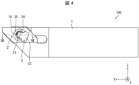
- It is the top view which looked at the cutting tool shown in FIG. 3 from B2 direction.
- FIG. 5 is a cross-sectional view taken along line VII-VII of FIG. 4
- 8 is an enlarged view of an area A2 shown in FIG. 7;
- FIG. 5 is a cross-sectional view taken along line VII-VII of FIG. 4;
- 8 is an enlarged view of an area A2 shown in FIG. 7;
- FIG. 5 is a cross-sectional view taken along line VII
- FIG. 1 is a schematic diagram illustrating one step in a method for manufacturing a machined workpiece in one non-limiting example
- FIG. 1 is a schematic diagram illustrating one step in a method for manufacturing a machined workpiece in one non-limiting example
- FIG. 1 is a schematic diagram illustrating one step in a method for manufacturing a machined workpiece in one non-limiting example
- FIG. 1 is a schematic diagram illustrating one step in a method for manufacturing a machined workpiece in one non-limiting example
- Cutting tools include, for example, turning tools and milling tools.
- Turning tools include, for example, grooving tools and parting off tools.
- the grooving tool can be used, for example, for grooving.
- the cutting tool 100 in one non-limiting example shown in FIG. 1 is a turning tool, and more specifically a grooving tool.
- the cutting tool 100 may comprise optional components not shown in the referenced figures.
- the dimensions of the members in each drawing do not necessarily represent the actual dimensions of the constituent members, the dimensional ratios of the respective members, and the like faithfully.
- the X-axis direction is the horizontal direction
- the Z-axis direction is the vertical direction
- the Y-axis direction is the front-back direction.
- the side where the insert 2 is positioned is the right side in the X-axis direction, the front side in the Y-axis direction, and the upper side in the Z-axis direction.
- a non-limiting example cutting tool 100 shown in FIGS. 1-8 includes a holder 1, an insert 2, a clamper 3, and a screw 4.
- the holder 1 may have a rod shape extending from the first end 1a toward the second end 1b along the first central axis L1. As shown in FIG. 1, the holder 1 may have a square prism shape.
- the first end 1a is also called “front end 1a”
- the second end 1b is also called “rear end 1b”.
- the front end 1a of the holder 1 in the Y-axis direction may be the front end 1a
- the rear end 1b may be the rear end 1b.
- the size of the holder 1 is not particularly limited.
- the length in the direction along the first central axis L1 can be set to approximately 5 mm to 100 mm.
- the height from the top end to the bottom end, in other words, the width in the vertical direction can be set to about 5 mm to 50 mm.
- Steel, cast iron, or the like may be used as the member of the holder 1 .
- the toughness of the holder 1 is high.
- the holder 1 may have a head 17 and a shank 18.
- the head 17 may be positioned on the tip 1a side of the holder 1 .
- the head 17 may include an end face on the side of the tip 1a, as shown in FIG.
- the shank 18 may be located closer to the rear end 1b than the head 17.
- the shank 18 may include an end face on the rear end 1b side, as shown in FIG.
- the shank 18 may be located closer to the rear end 1b than the head 17, and may include the central portion of the holder 1 in the direction along the first central axis L1, as shown in FIG.
- the shank 18 may be a part that is gripped by the machine tool when the cutting tool 100 is attached to the machine tool.
- the head 17 is a part for gripping the insert 2 and has a pocket 12 which will be described later.
- the shank 18 is generally a simple cylindrical or prismatic shape if it is a part that can be gripped by a machine tool. Therefore, the central axis of the shank 18 may be regarded as the first central axis L1 of the holder 1. As shown in FIG.
- the head 17 of the holder 1 may have a tip surface 11 , a pocket 12 , a first hole 13 and a second hole 14 .
- the tip surface 11 may be located on the tip 1a side of the head 17.
- the tip surface 11 is not limited to a configuration orthogonal to the first central axis L1.
- the distal end surface 11 may be configured to be inclined with respect to the first central axis L1.
- the tip surface 11 need not be formed by one plane.
- the distal end surface 11 may be formed by a plurality of flat surfaces, or may be formed by curved surfaces.
- the pocket 12 may be located on the tip 1a side of the head 17.
- the pocket 12 may be continuous with the tip surface 11 or may extend from the tip surface 11 toward the rear end 1b.
- An insert 2 can be attached to the pocket 12 .
- the pocket 12 is formed by cutting out the tip 1a side portion of the right side surface of the head 17.
- the pocket 12 has a bottom surface 121 parallel to the first central axis L1 and a bottom surface 121 perpendicular to the bottom surface 121. and a constraining side 122 that constrains the lower side 22 of the 2. Parallel here does not need to be exact.
- the bottom surface 121 may have a certain angle such as 5° with respect to the first central axis L1.
- the bottom surface 121 may be a surface on which the insert 2 abuts in the pocket 12 , or the insert 2 may be fixed to the pocket 12 by holding the insert 2 between the bottom surface 121 and the clamper 3 .
- the first hole 13 may extend from the bottom surface 121 at a constant angle with respect to the first central axis L1 of the holder 1 .
- "Forming a certain angle with respect to the first central axis L1" means that the second central axis L2 of the first hole 13 is not parallel to the first central axis L1 of the holder 1.
- the second central axis L2 may be orthogonal to the first central axis L1.
- the first hole 13 may penetrate the head 17 in the X-axis direction, or may have a bottom without penetrating the head 17 .
- the second hole 14 may extend from the tip surface 11 toward the rear end 1b. In the example shown in FIG. 7, the second hole 14 reaches the first hole 13 from the tip surface 11 and further extends from the first hole 13 toward the rear end 1b.
- a thread groove 15 is provided in a portion further extending from the first hole 13 toward the rear end 1b.
- the thread groove 15 is provided concentrically with the third central axis L3 of the second hole 14 .
- the third central axis L3 of the second hole 14 may have a certain angle with respect to the first central axis L1 of the holder 1, or may extend in parallel. When the third central axis L3 of the second hole 14 extends parallel to the first central axis L1 of the holder 1, the insert 2 can be replaced more easily.
- the second hole 14 may be perpendicular to the first hole 13 or may intersect at an acute angle. That is, the third central axis L3 of the second hole 14 may be orthogonal to the second central axis L2 of the first hole 13, or may intersect at an acute angle.
- the insert 2 located in the pocket 12 is not limited to any particular shape.
- the insert 2 may be square plate-shaped.
- the insert 2 is square plate-shaped, for example, the upper side surface 21, the lower side surface 22, the pair of lateral side surfaces 23, the first through hole 24, the notch portion 25, the front side surface 26, the rear side surface 27, and the cutting edge 28 are formed. may have.
- the upper surface 21 may be a surface of the insert 2 located above.
- the lower surface 22 may be the lower lying surface of the insert 2 .
- the pair of lateral sides 23 may be surfaces located between the upper side 21 and the lower side 22 . Assuming that the right side of the pair of lateral sides 23 is the right side 23a and the left side of the pair of lateral sides 23 is the left side 23b, the left side 23b contacts the bottom surface 121. As shown in FIG.
- the upper side surface 21, the lower side surface 22, and the pair of lateral side surfaces 23 may each extend in a direction along the first central axis L1.
- the front side surface 26 is a surface located on the tip 1a side of the insert 2, and may protrude forward from the tip 1a of the cutting tool 100.
- the rear side surface 27 is a surface located on the rear end 1b side of the insert 2 .
- the first through holes 24 may be opened on each of the pair of lateral side surfaces 23 .
- the first through hole 24 may extend from the right side 23a to the left side 23b.
- the first through holes 24 may be opened at the central portions of the pair of lateral side surfaces 23 .
- the clamper 3 is inserted into the first through hole 24 .
- the notch 25 may be formed in the right side 23a so as to be dug toward the left side 23b.
- the notch 25 is connected to the first through hole 24 and is formed to extend from the edge of the first through hole 24 on the rear end 1b side toward the rear end 1b.
- the notch portion 25 has a rectangular hole shape along the shape of the convex portion 32 .
- the first notch 25 may be separated from the first through hole 24 without being connected to the first through hole 24 .
- the insert 2 may be point symmetric with respect to the fourth central axis L4 of the first through hole 24.
- the upper surface 21 has a shape that matches the lower surface 22.
- the cutting edge 28 may be located at the intersection of the upper surface 21 and the front surface 26. Cutting can be performed by bringing this cutting edge 28 into contact with the material to be cut.
- the cutting edge 28 may be located at the intersection of the lower surface 22 and the rear surface 27 in addition to the locations described above.
- the insert 2 is called a two-corner type, which is economical.
- the size of the insert 2 is not particularly limited.
- the length in the direction along the first central axis L1 can be set to approximately 10 mm to 30 mm.
- the height from the upper side surface 21 to the lower side surface 22, in other words, the width in the vertical direction can be set to 5 mm to 15 mm.
- the width between the pair of lateral side surfaces 23 can be set to approximately 2 mm to 10 mm.
- Cemented carbide compositions may include, for example, WC--Co, WC--TiC--Co, and WC--TiC--TaC--Co.
- WC, TiC and TaC may be hard particles and Co may be the binder phase.
- the cermet may be a sintered composite material in which a metal is combined with a ceramic component.
- An example of a cermet may be a titanium compound based on titanium carbide (TiC) or titanium nitride (TiN).
- the material of the insert 2 is not limited to the above composition.
- the surface of the insert 2 may be coated with a coating formed using chemical vapor deposition (CVD) or physical vapor deposition (PVD) methods.
- the composition of the coating may include titanium carbide (TiC), titanium nitride (TiN), titanium carbonitride (TiCN), alumina (Al 2 O 3 ), and the like.
- the clamper 3 may be inserted into a first hole 13 provided in the holder 1 .
- a clamper 3 can constrain the insert 2 and may be used to fix the position of the insert 2 relative to the holder 1 .
- the position of the insert 2 may be fixed by applying a force from the clamper 3 to the insert 2 to press it toward the bottom surface 121 of the pocket 12 .
- the position of the insert 2 may be fixed while the clamper 3 is inserted into the first through hole 24 .
- a portion of the clamper 3 may be brought into contact with the vicinity of the opening of the first through hole 24 on the right side surface 23 a and the other portion of the clamper 3 may be inserted into the first through hole 24 .
- the other portion of the clamper 3 inserted into the first through hole 24 may be inserted into the first hole 13.
- the other portion of the clamper 3 inserted into the first through hole 24 is called a first portion.
- the first portion is drawn into the first hole 13 by tightening the screw 4 , which will be described later, so that the clamper 3 can apply a pressing force to the insert 2 toward the bottom surface 121 of the pocket 12 .
- the fixing of the insert 2 by the clamper 3 is not limited to the above configuration.
- the location where the clamper 3 abuts on the insert 2 is not limited to the vicinity of the opening of the first through hole 24 on the right side surface 23a.
- the portion of the insert 2 with which the clamper 3 abuts may be in the vicinity of the outer peripheral edge of the right side surface 23a.
- the clamper 3 is in contact with the right side surface 23a, and the upper side surface 21, the lower side surface 22, the front side surface 26, or the rear side surface 27 of the insert 2. may be inserted into the first hole 13 so as to wrap around the surface of the .
- the clamper 3 may contact the insert 2 on the rear end 1b side of the first hole 13 .
- the clamper 3 may contact a region of the right side surface 23 a that is closer to the rear end 1 b than the first hole 13 . In this case, the insert 2 is pulled toward the rear end 1b, and the binding force of the insert 2 can be increased.
- the clamper 3 may have a second through hole 33.
- the second through hole 33 may be provided in a portion of the clamper 3 that is inserted into the first hole 13 .
- the second through hole 33 may be opened so as to face the second hole 14 while the clamper 3 is inserted into the first hole 13 . That is, the second through hole 33 and the second hole 14 constitute one hole into which the screw 4 described below is inserted.
- the second through hole 33 has a circular shape larger than the outer diameter of the body of the screw 4, and the clamper 3 is just inserted into the first hole 13. In other words, the screw This is the state before tightening 4.
- the fifth center axis L5 of the second through-hole 33 is positioned closer to the opening of the first hole 13 than the third center axis L3 of the second hole 14 is.
- the second through-hole 33 may have a first tapered surface 34 positioned at the opening toward the second hole 14 .
- the second through hole 33 has a first tapered surface 34 as a portion whose inner diameter gradually decreases from the opening of the second through hole 33 toward the central portion of the second through hole 33. have.
- the second through-hole 33 does not necessarily have to be circular, and may be elongated in the X-axis direction.
- the arc-shaped portion of the second through-hole 33 on the side opposite to the opening of the first hole 13 is provided with a It is only necessary to have a portion (first tapered surface) where the inner diameter of the arc gradually decreases.
- the clamper 3 is not limited to a specific shape, it may be configured to slide in the extending direction of the second central axis L2 of the first hole 13 and not slide around the second central axis L2 of the first hole 13. With such a configuration, the direction of the opening of the second through hole 33 of the clamper 3 can be easily aligned with the second hole 14 of the holder 1 . Therefore, it is easy to insert the screw 4 into the second hole 14 and the second through hole 33, and the replacement work of the insert 2 becomes easier.
- the clamper 3 may be L-shaped with two sides. Let one of the two sides be the first side and the other be the second side.
- the clamper 3 is the first side, and includes the shaft portion 31 as the above-described first portion, the convex portion 32 projecting from the end portion of the shaft portion 31 as the second side, and the second through hole 33 described above. and have The second through-hole 33 is located near the tip of the shaft portion 31 and passes through the shaft portion 31 .
- the diameter of the second through hole 33 is smaller than the diameter of the first hole 13 .
- the convex portion 32 may have a shape in which, for example, a small rectangle and a large rectangle are connected when viewed from the side.
- the protrusion 32 may abut against the right side surface 23a of the insert 2 .
- the large rectangular portion of the projection 32 may be fitted into the cutout portion 25 so as to come into contact with the right side surface 23 a.
- the shaft portion 31 is inserted into the first through hole 24 and the first hole 13 . In this case, since the contact area between the insert 2 and the clamper 3 can be increased, the insert 2 can be firmly fixed by the clamper 3 .
- each shape is non-circular. It is good also as a structure which is a shape. Even with such a configuration, it is difficult for the clamper 3 to slide, in other words, rotate around the second central axis L2.
- the non-circular shape includes, for example, a flattened circular shape such as an elliptical shape, or a polygonal shape.
- the first portion in this cross section may have an elongated shape in the direction orthogonal to the central axis of the holder 1.
- the clamper 3 has the shaft portion 31 .
- the portion of the clamper 3 that is inserted into the first hole 13 has a second cutout portion 35 extending parallel to the second central axis L2, and the first hole 13 is the second cutout portion.
- a protrusion 16 corresponding to the notch 35 may be provided. Even in such a case, the clamper 3 is less likely to rotate around the second central axis L2.
- the material of the clamper 3 for example, steel, cast iron, etc. may be used. In particular, when steel is used among these members, the clamper 3 has high toughness.
- the screw 4 may be inserted into the second hole 14 and the second through hole 33 .
- the screw 4 may have a thread 42 screwed into the second hole 14 and a second tapered surface 41 .
- the screw 4 may have a second tapered surface 41 as a portion whose outer diameter decreases from the head toward the tip.
- the second tapered surface 41 may include up to the tip of the screw 4 or may be provided at a portion away from the tip of the screw 4 .
- the second tapered surface 41 of the screw 4 comes into contact with the first tapered surface 34 positioned at the opening of the second through hole 33 of the clamper 3 .
- the fifth central axis L5 of the second through-hole 33 is located closer to the opening of the first hole 13 than the third central axis L3 of the second hole 14, so that it is shown in FIG. , the second tapered surface 41 may contact the first tapered surface 34 only on the side opposite to the opening side of the first hole 13 .
- the clamper 3 firmly fixes the position of the insert 2 with respect to the holder 1 . Then, the screw 4 can be easily loosened from the opening of the second hole 14 located on the side of the tip 1a to release the restraint of the insert 2 by the clamper 3, and the insert 2 can be replaced. For example, when machining is performed by arranging a plurality of cutting tools 100 on a comb blade turret, the distance between the heads 17 is narrow and it is difficult to rotate the side lock member. The clamper 3 can be unlocked by easily loosening the screw 4 from the front side.
- the screw groove 15 may be formed in a portion closer to the opening of the second hole 14 than the second through hole 33, and may be formed further from the opening of the second hole 14 than the second through hole 33 as described above. It may be formed in parts.
- the thread 42 may be located closer to the tip 1a than the second tapered surface 41, and may be located closer to the rear end 1b than the second tapered surface 41.
- the screw 4 is less likely to loosen.
- the outer diameter of the second tapered surface 41 may be larger than the outer diameter of the screw thread 42 .
- the area of the second tapered surface 41 can be increased, and the contact area between the screw 4 and the clamper 3 can be increased. Therefore, the screws 4 are less likely to loosen.
- the first hole 13 extends from the bottom surface 121 toward the first central axis L1 of the holder 1, and the second hole 14 extends from the front end surface 11 of the holder 1 toward the rear end 1b.
- the clamper 3 When extended, the clamper 3 can be firmly fixed. Then, the screw 4 can be easily loosened and the insert 2 can be replaced.
- the direction in which the insert 2 is clamped is the direction in which the first hole 13 extends
- the direction in which the first hole 13 extends and the direction in which the second hole 14 extends are not parallel to each other, but cross each other. Looseness of 4 is less likely to occur.
- the second hole 14 extends from the tip surface 11 of the holder 1 toward the rear end 1b, so that the operator can easily see the screw 4 and easily turn the screw 4 when replacing the insert 2. Easy.
- steel, cast iron, or the like may be used as the material of the screw 4.
- the toughness of the screw 4 is high.
- a workpiece 101 is produced by cutting a workpiece 103 .
- the manufacturing method of the cut workpiece 101 in the embodiment includes the following steps. Namely (1) a step of rotating the work material 103; (2) A step of contacting the rotating work material 103 with the cutting tool 100 represented by the above embodiment; (3) separating the cutting tool 100 from the work material 103; Prepare.
- the work piece 103 may be rotated around the sixth central axis L6, and the cutting tool 100 may be brought relatively closer to the work piece 103.
- the cutting tool 100 may be brought into contact with the work material 103 to cut the work material 103 .
- the cutting tool 100 may be kept away from the workpiece 103 or the workpiece 101 to be cut.
- the cutting tool 100 is moved in the forward direction of the Y-axis while at least part of the portion of the insert 2 used as the cutting edge 28 is in contact with the rotating work 103.
- the work material 103 may be cut.
- the cutting tool 100 may be moved away from the work material 103 by moving the cutting tool 100 in the rearward direction of the Y-axis while the work material 103 is being rotated.
- the cutting tool 100 is brought into contact with the work material 103 or separated from the work material 103 by moving the cutting tool 100, but the present invention is not limited to this case.
- step (1) the work material 103 may be brought closer to the cutting tool 100 .
- step (3) the work material 103 may be kept away from the cutting tool 100 .
- the process of keeping the workpiece 103 rotated and bringing at least part of the cutting edge 28 of the insert 2 into contact with a different portion of the workpiece 103 may be repeated. .
- Representative examples of the material of the work material 103 include hardened steel, carbon steel, alloy steel, stainless steel, cast iron, non-ferrous metals, and the like.
- the insert 2 since the insert 2 is well fixed to the holder 1 by the cutting tool 100 of the present disclosure, machining can be performed with high accuracy.
- the screw 4 can be easily loosened from the front of the holder 1 to unlock the clamper 3, resulting in good working efficiency.
Landscapes
- Engineering & Computer Science (AREA)
- Mechanical Engineering (AREA)
- Cutting Tools, Boring Holders, And Turrets (AREA)
Priority Applications (1)
| Application Number | Priority Date | Filing Date | Title |
|---|---|---|---|
| JP2023552860A JP7757411B2 (ja) | 2021-10-04 | 2022-10-03 | 切削工具、及び切削加工物の製造方法 |
Applications Claiming Priority (2)
| Application Number | Priority Date | Filing Date | Title |
|---|---|---|---|
| JP2021163635 | 2021-10-04 | ||
| JP2021-163635 | 2021-10-04 |
Publications (1)
| Publication Number | Publication Date |
|---|---|
| WO2023058589A1 true WO2023058589A1 (ja) | 2023-04-13 |
Family
ID=85804226
Family Applications (1)
| Application Number | Title | Priority Date | Filing Date |
|---|---|---|---|
| PCT/JP2022/036898 Ceased WO2023058589A1 (ja) | 2021-10-04 | 2022-10-03 | 切削工具、及び切削加工物の製造方法 |
Country Status (2)
| Country | Link |
|---|---|
| JP (1) | JP7757411B2 (https=) |
| WO (1) | WO2023058589A1 (https=) |
Cited By (2)
| Publication number | Priority date | Publication date | Assignee | Title |
|---|---|---|---|---|
| WO2025089042A1 (ja) * | 2023-10-25 | 2025-05-01 | 京セラ株式会社 | 切削工具及び切削加工物の製造方法 |
| WO2025154369A1 (ja) * | 2024-01-16 | 2025-07-24 | 京セラ株式会社 | 切削工具、及び切削加工物の製造方法 |
Citations (8)
| Publication number | Priority date | Publication date | Assignee | Title |
|---|---|---|---|---|
| JPH10100006A (ja) * | 1996-09-30 | 1998-04-21 | Kyocera Corp | クランプバイト |
| JP2001062606A (ja) * | 1999-08-23 | 2001-03-13 | Mitsubishi Materials Corp | スローアウェイチップのクランプ機構 |
| JP2002512891A (ja) * | 1998-04-29 | 2002-05-08 | イスカー・リミテツド | 切削工具アセンブリとその中で使用するための切削インサート |
| JP2004538163A (ja) * | 2001-08-12 | 2004-12-24 | イスカーリミテッド | 切削工具 |
| US20110142556A1 (en) * | 2007-12-19 | 2011-06-16 | Hartmetall-Werkzeugfabrik Paul Horn Gmbh | Tool for machining, in particular longitudinal turning tool |
| WO2012153737A1 (ja) * | 2011-05-12 | 2012-11-15 | 株式会社タンガロイ | 切削インサートのクランプ装置、切削工具および切削インサート |
| JP2012254514A (ja) * | 2011-06-10 | 2012-12-27 | Mitsubishi Materials Corp | 切削インサートのクランプ機構、ホルダ、切削インサート及び切削工具 |
| JP2015514596A (ja) * | 2012-04-19 | 2015-05-21 | イスカル リミテッド | レバーピンを有する切削工具および切削工具ホルダ |
Family Cites Families (2)
| Publication number | Priority date | Publication date | Assignee | Title |
|---|---|---|---|---|
| US8740511B2 (en) | 2011-12-08 | 2014-06-03 | Iscar, Ltd. | Tool holder and method for clamping a cutting insert therein |
| US9656326B2 (en) | 2013-04-24 | 2017-05-23 | Iscar, Ltd. | Tool holder having a clamping member with a non-circular cross-section and method for clamping a cutting insert therein |
-
2022
- 2022-10-03 JP JP2023552860A patent/JP7757411B2/ja active Active
- 2022-10-03 WO PCT/JP2022/036898 patent/WO2023058589A1/ja not_active Ceased
Patent Citations (8)
| Publication number | Priority date | Publication date | Assignee | Title |
|---|---|---|---|---|
| JPH10100006A (ja) * | 1996-09-30 | 1998-04-21 | Kyocera Corp | クランプバイト |
| JP2002512891A (ja) * | 1998-04-29 | 2002-05-08 | イスカー・リミテツド | 切削工具アセンブリとその中で使用するための切削インサート |
| JP2001062606A (ja) * | 1999-08-23 | 2001-03-13 | Mitsubishi Materials Corp | スローアウェイチップのクランプ機構 |
| JP2004538163A (ja) * | 2001-08-12 | 2004-12-24 | イスカーリミテッド | 切削工具 |
| US20110142556A1 (en) * | 2007-12-19 | 2011-06-16 | Hartmetall-Werkzeugfabrik Paul Horn Gmbh | Tool for machining, in particular longitudinal turning tool |
| WO2012153737A1 (ja) * | 2011-05-12 | 2012-11-15 | 株式会社タンガロイ | 切削インサートのクランプ装置、切削工具および切削インサート |
| JP2012254514A (ja) * | 2011-06-10 | 2012-12-27 | Mitsubishi Materials Corp | 切削インサートのクランプ機構、ホルダ、切削インサート及び切削工具 |
| JP2015514596A (ja) * | 2012-04-19 | 2015-05-21 | イスカル リミテッド | レバーピンを有する切削工具および切削工具ホルダ |
Cited By (2)
| Publication number | Priority date | Publication date | Assignee | Title |
|---|---|---|---|---|
| WO2025089042A1 (ja) * | 2023-10-25 | 2025-05-01 | 京セラ株式会社 | 切削工具及び切削加工物の製造方法 |
| WO2025154369A1 (ja) * | 2024-01-16 | 2025-07-24 | 京セラ株式会社 | 切削工具、及び切削加工物の製造方法 |
Also Published As
| Publication number | Publication date |
|---|---|
| JPWO2023058589A1 (https=) | 2023-04-13 |
| JP7757411B2 (ja) | 2025-10-21 |
Similar Documents
| Publication | Publication Date | Title |
|---|---|---|
| KR101330482B1 (ko) | 인서트 탈착식 공구 | |
| WO2023058589A1 (ja) | 切削工具、及び切削加工物の製造方法 | |
| CN1826201A (zh) | 用于回转式切削工具的切削头 | |
| JP5056019B2 (ja) | 刃部交換式切削工具 | |
| JP7368064B2 (ja) | 工作機械及び切削加工物の製造方法 | |
| JP7102283B2 (ja) | ホルダ、切削工具及び切削加工物の製造方法 | |
| JP7756789B2 (ja) | 切削工具及び切削加工物の製造方法 | |
| CN113474110B (zh) | 车削刀具及切削加工物的制造方法 | |
| JP7594672B2 (ja) | 切削インサート、切削工具及び切削加工物の製造方法 | |
| JP7592867B2 (ja) | 切削インサート、切削工具及び切削加工物の製造方法 | |
| JP2013244583A (ja) | 交換式旋削加工用ヘッドおよびヘッド交換式旋削工具 | |
| JP7727750B2 (ja) | 切削工具及び切削加工物の製造方法 | |
| WO2024147242A1 (ja) | 切削工具及び切削加工物の製造方法 | |
| US20260061499A1 (en) | Cutting unit, cutting tool, cutting tool rest, and method for manufacturing cut article | |
| WO2025154369A1 (ja) | 切削工具、及び切削加工物の製造方法 | |
| JP2026017167A (ja) | 切削工具及び切削加工物の製造方法 | |
| JP7527489B2 (ja) | ホルダ、切削工具及び切削加工物の製造方法 | |
| JP7711205B2 (ja) | ホルダ、切削工具、及び切削加工物の製造方法 | |
| CN113795344B (zh) | 夹紧构件、机床以及切削加工物的制造方法 | |
| JP4262049B2 (ja) | 切削工具 | |
| JP2024123701A (ja) | 切削インサート、ホルダ及び切削工具 | |
| JP7117389B2 (ja) | 切削インサート、切削工具及び切削加工物の製造方法 | |
| TWM650329U (zh) | 車刀組合結構 | |
| WO2024180831A1 (ja) | ホルダ、切削工具及び切削加工物の製造方法 | |
| WO2025089042A1 (ja) | 切削工具及び切削加工物の製造方法 |
Legal Events
| Date | Code | Title | Description |
|---|---|---|---|
| 121 | Ep: the epo has been informed by wipo that ep was designated in this application |
Ref document number: 22878458 Country of ref document: EP Kind code of ref document: A1 |
|
| WWE | Wipo information: entry into national phase |
Ref document number: 2023552860 Country of ref document: JP |
|
| NENP | Non-entry into the national phase |
Ref country code: DE |
|
| 122 | Ep: pct application non-entry in european phase |
Ref document number: 22878458 Country of ref document: EP Kind code of ref document: A1 |