WO2023058241A1 - 追従プログラム、追従方法および情報処理装置 - Google Patents
追従プログラム、追従方法および情報処理装置 Download PDFInfo
- Publication number
- WO2023058241A1 WO2023058241A1 PCT/JP2021/037415 JP2021037415W WO2023058241A1 WO 2023058241 A1 WO2023058241 A1 WO 2023058241A1 JP 2021037415 W JP2021037415 W JP 2021037415W WO 2023058241 A1 WO2023058241 A1 WO 2023058241A1
- Authority
- WO
- WIPO (PCT)
- Prior art keywords
- head
- person
- image
- dimensional
- head region
- Prior art date
- Legal status (The legal status is an assumption and is not a legal conclusion. Google has not performed a legal analysis and makes no representation as to the accuracy of the status listed.)
- Ceased
Links
Images


Classifications
-
- G—PHYSICS
- G06—COMPUTING OR CALCULATING; COUNTING
- G06T—IMAGE DATA PROCESSING OR GENERATION, IN GENERAL
- G06T7/00—Image analysis
- G06T7/20—Analysis of motion
- G06T7/292—Multi-camera tracking
-
- G—PHYSICS
- G06—COMPUTING OR CALCULATING; COUNTING
- G06V—IMAGE OR VIDEO RECOGNITION OR UNDERSTANDING
- G06V40/00—Recognition of biometric, human-related or animal-related patterns in image or video data
- G06V40/10—Human or animal bodies, e.g. vehicle occupants or pedestrians; Body parts, e.g. hands
-
- G—PHYSICS
- G06—COMPUTING OR CALCULATING; COUNTING
- G06T—IMAGE DATA PROCESSING OR GENERATION, IN GENERAL
- G06T7/00—Image analysis
- G06T7/20—Analysis of motion
- G06T7/246—Analysis of motion using feature-based methods, e.g. the tracking of corners or segments
-
- G—PHYSICS
- G06—COMPUTING OR CALCULATING; COUNTING
- G06T—IMAGE DATA PROCESSING OR GENERATION, IN GENERAL
- G06T7/00—Image analysis
- G06T7/20—Analysis of motion
- G06T7/285—Analysis of motion using a sequence of stereo image pairs
-
- G—PHYSICS
- G06—COMPUTING OR CALCULATING; COUNTING
- G06T—IMAGE DATA PROCESSING OR GENERATION, IN GENERAL
- G06T7/00—Image analysis
- G06T7/50—Depth or shape recovery
- G06T7/536—Depth or shape recovery from perspective effects, e.g. by using vanishing points
-
- G—PHYSICS
- G06—COMPUTING OR CALCULATING; COUNTING
- G06T—IMAGE DATA PROCESSING OR GENERATION, IN GENERAL
- G06T7/00—Image analysis
- G06T7/70—Determining position or orientation of objects or cameras
-
- G—PHYSICS
- G06—COMPUTING OR CALCULATING; COUNTING
- G06V—IMAGE OR VIDEO RECOGNITION OR UNDERSTANDING
- G06V20/00—Scenes; Scene-specific elements
- G06V20/50—Context or environment of the image
- G06V20/52—Surveillance or monitoring of activities, e.g. for recognising suspicious objects
-
- G—PHYSICS
- G06—COMPUTING OR CALCULATING; COUNTING
- G06T—IMAGE DATA PROCESSING OR GENERATION, IN GENERAL
- G06T2207/00—Indexing scheme for image analysis or image enhancement
- G06T2207/10—Image acquisition modality
- G06T2207/10016—Video; Image sequence
-
- G—PHYSICS
- G06—COMPUTING OR CALCULATING; COUNTING
- G06T—IMAGE DATA PROCESSING OR GENERATION, IN GENERAL
- G06T2207/00—Indexing scheme for image analysis or image enhancement
- G06T2207/30—Subject of image; Context of image processing
- G06T2207/30196—Human being; Person
-
- G—PHYSICS
- G06—COMPUTING OR CALCULATING; COUNTING
- G06T—IMAGE DATA PROCESSING OR GENERATION, IN GENERAL
- G06T2207/00—Indexing scheme for image analysis or image enhancement
- G06T2207/30—Subject of image; Context of image processing
- G06T2207/30232—Surveillance
-
- G—PHYSICS
- G06—COMPUTING OR CALCULATING; COUNTING
- G06T—IMAGE DATA PROCESSING OR GENERATION, IN GENERAL
- G06T2207/00—Indexing scheme for image analysis or image enhancement
- G06T2207/30—Subject of image; Context of image processing
- G06T2207/30241—Trajectory
Definitions
- the present invention relates to a follow-up program and the like.
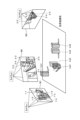
- FIG. 25 is a diagram for explaining an example of a person tracking result.
- image M1 is an image captured by camera c1.
- the image M2 is an image captured by the camera c2.
- the image M3 is an image captured by the camera c3. Based on the position of the same person in each image frame included in the images M1 to M3 and the parameters of the cameras c1 to c3, by repeating the process of calculating the position of the person in three dimensions (world coordinate system), 3 Follow a dimensional person.
- the person 1-1 in the image M1 and the person 2-1 in the image M2 are the same person, and the three-dimensional tracking result of this person is the trajectory tra1.
- the person 1-2 in the image M1, the person 2-2 in the image M2, and the person 3-2 in the image M3 are the same person, and the three-dimensional tracking result of this person is the trajectory tra2.
- the person 1-3 in the image M1, the person 2-3 in the image M2, and the person 3-3 in the image M3 are the same person, and the three-dimensional tracking result of this person is the trajectory tra3.
- the person 1-4 in the image M1, the person 2-4 in the image M2, and the person 3-4 in the image M3 are the same person, and the three-dimensional tracking result of this person is the trajectory tra4.
- the person 1-5 in the image M1, the person 2-5 in the image M2, and the person 3-5 in the image M3 are the same person, and the three-dimensional tracking result of this person is the trajectory tra5.
- FIG. 26 is a diagram for explaining prior art 1.
- FIG. A device that implements the prior art 1 is referred to as a conventional device 10 .
- the conventional device 10 has a single MOT (Multiple Object Tracking) 11 , a three-dimensional trajectory calculation section 12 and an association processing section 13 .
- MOT Multiple Object Tracking
- the single MOT 11 Upon receiving the two-dimensional area information 1a, 1b, 1c (other two-dimensional area information), the single MOT 11 generates two-dimensional locus information 2a, 2b, 2c (other two-dimensional locus information).
- the two-dimensional area information 1a is the two-dimensional coordinates (2d bboxes) of the person's area extracted from the video (successive image frames) captured by the camera c1.
- the two-dimensional area information 1b is the two-dimensional coordinates of the person's area extracted from the image captured by the camera c2.
- the two-dimensional area information 1c is the two-dimensional coordinates of the person's area extracted from the image captured by the camera c3.
- the two-dimensional trajectory information 2a is trajectory information calculated by following the continuous two-dimensional area information 1a.
- the two-dimensional trajectory information 2b is trajectory information calculated by following the continuous two-dimensional area information 1b.
- the two-dimensional trajectory information 2c is trajectory information calculated by following the continuous two-dimensional area information 1c.
- the three-dimensional trajectory calculation unit 12 Upon receiving the two-dimensional trajectory information 2a, 2b, 2c (other two-dimensional trajectory information), the three-dimensional trajectory calculation unit 12 calculates the three-dimensional trajectory information 3a, 3b, 3c ( other three-dimensional trajectory information).
- the three-dimensional trajectory calculation unit 12 calculates the three-dimensional trajectory information 3a based on the two-dimensional trajectory information 2a.
- the three-dimensional trajectory calculator 12 calculates three-dimensional trajectory information 3b based on the two-dimensional trajectory information 2b.
- the three-dimensional trajectory calculator 12 calculates three-dimensional trajectory information 3c based on the two-dimensional trajectory information 2c.
- the association processing unit 13 performs association based on the three-dimensional trajectory information 3a, 3b, 3c (other three-dimensional trajectory information) and generates the three-dimensional trajectory information 4. For example, the association processing unit 13 calculates the Eugrid distance of each locus from the three-dimensional locus information 3a, 3b, and 3c, and associates the three-dimensional locus information 3a, 3b, and 3c based on the Eugrid distance, 3D trajectory information 4 is generated.
- the conventional device 10 tracks the position of the person in three dimensions by repeatedly executing the above process.
- FIG. 27 is a diagram for explaining conventional technique 2.
- FIG. A device that implements the prior art 2 is referred to as a conventional device 20 .
- the conventional device 20 has an association processing unit 21 and an MOT 22 .
- the association processing unit 21 generates three-dimensional posture information 6 based on the two-dimensional posture information 5a, 5b, and 5c (other two-dimensional posture information).
- the two-dimensional posture information 5a is information of a person's posture extracted from video (continuous image frames) captured by the camera c1, and includes information such as joint positions.
- the two-dimensional posture information 5b is information on the posture of the person extracted from the video captured by the camera c2, and includes information such as joint positions of the person.
- the two-dimensional posture information 5c is information on the posture of the person extracted from the video captured by the camera c3, and includes information such as joint positions.
- the association processing unit 21 calculates the two-dimensional posture information 5a, 5b based on the distance, similarity, etc. between the epipolar line and the person specified from the two-dimensional posture information 5a, 5b, 5c (other two-dimensional posture information). , 5c are associated to generate three-dimensional posture information 6.
- FIG. The three-dimensional posture information 6 is three-dimensional posture information of a person, and includes information such as joint positions of the person.
- the MOT 22 generates three-dimensional trajectory information 7 based on the three-dimensional posture information 6.
- the three-dimensional trajectory information 7 is information on a three-dimensional human trajectory.
- the conventional device 20 tracks the position of the person in three dimensions by repeatedly executing the above process.
- FIG. 28 is a diagram for explaining the problem of the conventional technology.
- the 3 Compute the dimensional coordinates For example, the three-dimensional coordinates of the person P1 are calculated from the area A1 of the person included in the image Im1 of the camera c1. Also, the three-dimensional coordinates of the person P1 are calculated from the area A2 of the person included in the image Im2 of the camera c2.
- the Z-axis coordinates of the feet of the person P1 do not become 0 (Z ⁇ 0), so the three-dimensional coordinates of the person P1 cannot be calculated with high accuracy. and fail to follow.
- an object of the present invention is to provide a tracking program, a tracking method, and an information processing apparatus that can accurately track a person's three-dimensional position.
- the computer executes the following processing.
- the computer identifies a person's head region from a plurality of images captured by each of the plurality of cameras.
- the computer identifies a set of head regions corresponding to the same person based on the positions of the head regions identified from the plurality of images.
- the computer identifies the three-dimensional position of the person's head based on the two-dimensional positions of the set of head regions of the same person and the parameters set for each of the plurality of cameras.
- a person's 3D coordinates can be tracked.
- FIG. 1 is a diagram showing an example of a system according to the first embodiment.
- FIG. 2 is a diagram illustrating a configuration example of an information processing apparatus according to the first embodiment.
- FIG. 3 is a diagram illustrating an example of the data structure of a video DB.
- FIG. 4 is a diagram showing an example of the detection result of the head region.
- FIG. 5 is a diagram for explaining an example of single MOT processing.
- FIG. 6 is a diagram for explaining the processing of the first interpolation unit.
- FIG. 7 is a diagram (1) for explaining the processing of the association processing unit;
- FIG. 8 is a diagram (2) for explaining the processing of the association processing unit.
- FIG. 9 is a diagram (3) for explaining the processing of the association processing unit;
- FIG. 10 is a diagram (4) for explaining the processing of the association processing unit;
- FIG. 11 is a diagram (1) for explaining the processing of the calculation processing unit;
- FIG. 12 is a diagram (2) for explaining the processing of the calculation processing unit;
- FIG. 13 is a diagram for explaining the processing of the second interpolation unit;
- FIG. 14 is a flow chart showing the processing procedure of the information processing apparatus according to the first embodiment.
- FIG. 15 is a diagram illustrating an example of a system according to the second embodiment.
- FIG. 16 is a diagram for explaining processing of the information processing apparatus according to the second embodiment.
- FIG. 17 is a diagram showing the result of association according to the prior art.
- FIG. 18 is a diagram showing an example of an association error in the prior art.
- FIG. 19 is a diagram (1) showing the result of association by the information processing apparatus of the second embodiment.
- FIG. 20 is a diagram (2) showing the result of association by the information processing apparatus of the second embodiment.
- FIG. 21 is a diagram illustrating a configuration example of an information processing apparatus according to the second embodiment.
- FIG. 22 is a diagram for explaining the processing of the association processing unit 250 according to the second embodiment.
- FIG. 23 is a flow chart showing the processing procedure of the information processing apparatus according to the second embodiment.
- FIG. 24 is a diagram illustrating an example of a hardware configuration of a computer that implements functions similar to those of the information processing apparatus of the embodiment.
- FIG. 25 is a diagram for explaining an example of a person tracking result.
- FIG. 26 is a diagram for explaining Conventional Technique 1.
- FIG. FIG. 27 is a diagram for explaining conventional technique 2.
- FIG. FIG. 28 is a diagram for explaining the problem of the prior art.
- FIG. 1 is a diagram showing an example of a system according to the first embodiment. As shown in FIG. 1, this system has a plurality of cameras c1, c2, c3, a data acquisition device 60, and an information processing device 100. FIG. The cameras c1-c3 and the data acquisition device 60 are interconnected via a network 50. FIG. Although cameras c1 to c3 are shown in FIG. 1, the system according to the first embodiment may further include other cameras.
- Cameras c1 to c3 are cameras that capture images inside convenience stores, supermarkets, and the like.
- the cameras c 1 to c 3 transmit video data to the data acquisition device 60 .
- video data is referred to as "video data”.
- the cameras c1 to c3 are simply referred to as “cameras” when they are not distinguished from each other.
- Video data includes multiple image frames in time series.
- a frame number is assigned to each image frame in ascending chronological order.
- One image frame is a still image captured by a camera at a certain timing.
- the data acquisition device 60 receives video data from the cameras c1 to c3 and registers the received video data in a video DB (Data Base) 65.
- the video DB 65 is set in the information processing apparatus 100 by the user or the like. In the first embodiment, the information processing apparatus 100 is assumed to be offline as an example. may be sent to
- the information processing device 100 is a device that generates 3D trajectory information by following a person in 3D based on each image frame (video data) registered in the video DB 65 .
- the information processing apparatus 100 identifies the region of the person's head and the epipolar line from each image frame registered in the video DB 65 .
- the area of the person's head is referred to as a "head area”.
- the information processing apparatus 100 identifies a set of head regions corresponding to the same person based on the head region, the epipolar line, and the distance identified from each image frame, and based on the set of identified head regions, Calculate the three-dimensional coordinates of the person's head.
- the information processing apparatus 100 generates three-dimensional trajectory information regarding the person's head region by repeatedly executing such processing.
- Cameras are usually installed in high places, so even if multiple people are crowded together, the head area is less susceptible to occlusion, and most cameras can capture multiple people's head areas. is. Therefore, compared with the case of using the area information of the whole body of the person as in the conventional technology, the head area is less likely to be lost, and the position of the person (the position of the head area) can be stably tracked. be able to.
- the information processing apparatus 100 extracts only the head region, the calculation cost can be reduced and the processing speed can be increased compared to the case of specifying the region information and posture of the whole body of the person as in the conventional technology. can be done.
- the information processing apparatus 100 identifies a set of head regions corresponding to the same person based on the head regions, epipolar lines, and distances of the persons identified from each image frame. Therefore, it is possible to prevent the head regions of different persons from being identified as the same set, and to accurately track the three-dimensional position of the person.
- FIG. 2 is a diagram illustrating a configuration example of an information processing apparatus according to the first embodiment.
- the information processing apparatus 100 includes a video DB 65, a head region specifying unit 110, a single MOT 111, a first interpolation unit 112, an association processing unit 113, a calculation processing unit 114, a second and an interpolation unit 115 .
- the head region identification unit 110, single MOT 111, first interpolation unit 112, association processing unit 113, calculation processing unit 114, and second interpolation unit 115 are implemented by a control unit such as a CPU.
- the head region specifying unit 110 is an example of a first specifying unit.
- the association processing unit 113 is an example of a second specifying unit.
- the calculation processing unit 114 is an example of a third specifying unit.
- the video DB 65 is a DB that stores video data captured by cameras c1, c2, c3, and the like.
- FIG. 3 is a diagram illustrating an example of the data structure of a video DB.
- the video DB 65 stores camera identification information and video data in association with each other.
- Camera identification information is information that uniquely identifies a camera.
- cam1 indicates camera c1.
- cam2 indicates camera c2.
- cam3 indicates camera c3.
- the video data is video data captured by the corresponding camera.
- the video data includes time-series image frames and is given a frame number.
- the head region identifying unit 110 identifies the head region of the person by analyzing each image frame captured by each camera registered in the video DB 65, and sets the two-dimensional coordinates of the head region of the person. Dimensional region information 8a, 8b, 8c is output.
- the head region identifying unit 110 uses a machine-learned detection model.
- the detection model is a machine learning model that detects the head region of a person included in the image frames when time-series image frames included in the video data are input. A person detected from an image frame is assigned a person ID for identifying the person.
- the detection model is realized by an open source machine learning model or the like.
- FIG. 4 is a diagram showing an example of the detection result of the head region.
- head areas HA1a, HA1b, HA1c, HA1d, and HA1e of each person are detected from an image frame frame1 captured by a certain camera.
- the head region specifying unit 110 sets two-dimensional coordinates (2d bboxes) of the head regions HA1a to HA1e of each person, person IDs, etc., and generates two-dimensional region information.
- the head area specifying unit 110 generates two-dimensional area information 8a based on each image frame captured by the camera c1 and outputs it to the single MOT111.
- the head region specifying unit 110 generates two-dimensional region information 8b based on each image frame captured by the camera c2, and outputs it to the single MOT 111.
- the head area specifying unit 110 generates the two-dimensional area information 8c based on each image frame captured by the camera c3 and outputs it to the single MOT111.
- the head region specifying unit 110 may further generate two-dimensional region information based on each image frame captured by another camera.
- the single MOT 111 Upon receiving the two-dimensional area information 8a, 8b, 8c, the single MOT 111 generates two-dimensional trajectory information 9a, 9b, 9c. Single MOT 111 outputs two-dimensional trajectory information 9 a , 9 b , 9 c to first interpolation section 112 .
- FIG. 5 is a diagram for explaining an example of single MOT processing.
- Image frames frame k-1, frame k, and frame k+1 shown in FIG. 5 are consecutive image frames captured by the same camera and correspond to two-dimensional area information specified from each image frame.
- An image frame frame k-1 includes head areas HA1a, HA1b, and HA1c.
- the image frame frame k includes head areas HA2a, HA2b, and HA2c.
- the image frame frame k includes head areas HA3a, HA3b, and HA3c.
- the single MOT 111 identifies the head region of the same person based on the distance of the head region in each image frame.
- the single MOT 111 links the head areas HA1a, HA2a, and HA3a, respectively.
- the single MOT 111 links the head areas HA1b, HA2b, and HA3b, assuming that the head areas HA1b, HA2b, and HA3b are the head areas of the same person.
- the single MOT 111 links the head areas HA1a, HA2a, and HA3a, respectively.
- the single MOT 111 generates two-dimensional trajectory information from each two-dimensional area information corresponding to each image frame captured by the same camera by executing the processing shown in FIG.
- the single MOT 111 uses the technology described in the non-patent document (Ramana Sundararaman et al "Tracking Pedestrian Heads in Dense Crowd” arXiv:2103.13516v1 [cs.CV] 24 Mar 2021) to obtain each two-dimensional area information , two-dimensional trajectory information can be generated.
- the first interpolating unit 112 receives the two-dimensional trajectory information 9a to 9c, and interpolates the head region using the information on the preceding and succeeding head regions when there is a gap or the like in the head region in a certain image frame.
- the first interpolator 112 outputs the interpolated two-dimensional trajectory information 9 a to 9 c to the association processor 113 .
- FIG. 6 is a diagram for explaining the processing of the first interpolation unit.
- the head region is not detected in the image frame frame k before interpolation.
- the head areas HA1a, HA1b, and HA1c are detected in the image frame frame k-1 before interpolation.
- Head areas HA3a, HA3b, and HA3c are detected in the image frame frame k+1 before interpolation.
- the first interpolation unit 112 calculates the head region of the image frame frame k Interpolate HA2a. Based on the two-dimensional coordinates of the head region HA1b of the image frame frame k-1 and the two-dimensional coordinates of the head region HA3b of the image frame frame k+1, the first interpolation unit 112 calculates the head region of the image frame frame k. Interpolate HA2b.
- the first interpolation unit 112 calculates the head region of the image frame frame k. Interpolate HA2c.
- the head areas HA2a, HA2b, and HA2c of the image frame frame k are set after interpolation.
- the association processing unit 113 Based on the two-dimensional trajectory information 9a to 9c, the association processing unit 113 associates head areas corresponding to the same person with respect to head areas between image frames captured by different cameras. 7 to 10 are diagrams for explaining the processing of the association processing unit.
- FIG. 7 will be described.
- the image frame 10-1 is an image frame included in video data captured by the camera c1.
- Image frame 10-1 includes a person's head area HA10. Assume that the height of the head area HA10 is “h 1 ” and the width is “w 1 ”.
- the image frame 10-2 is an image frame included in the video data shot by the camera c2.
- Image frame 10-2 includes a person's head area HA11. Assume that the height of the head area HA10 is “h 2 " and the width is "w 2 ".
- the image frame 10-1 and the image frame 10-2 are assumed to be image frames shot at the same timing. For example, let the frame number of the image frame 10-1 and the frame number of the image frame 10-2 be the same.
- the association processing unit 113 identifies the epipolar line l(x 2 , 0) on the image frame Im10-1 based on the parameters of the cameras c1 and c2 and the central coordinate x2 of the head area HA11. This means that the center coordinate x 2 of the head region HA11 is included on the epipolar line l(x 2 , 0).
- the association processing unit 113 calculates the distance d(l(x 2 ), x 1 ) between the central coordinate x 1 of the head region HA10 and the epipolar line l(x 2 ) on the image frame Im10-1.
- the association processing unit 113 divides the distance d(l(x 2 ), x 1 ) by ((w 1 +h 1 )/2) to adjust the scale, and divides the head region HA10 and the head region HA11. Calculate the epipolar distance.
- the association processing unit 113 identifies the epipolar line l(x 1 ) on the image frame Im10-2 based on the parameters of the cameras c1 and c2 and the central coordinate x 1 of the head region HA10. This means that the central coordinate x 1 of the head region HA10 is included on the epipolar line l(x 1 ).
- the association processing unit 113 divides the distance d(l(x 1 ), x 2 ) by ((w 2 +h 2 )/2) to adjust the scale, and divides the head region HA10 and the head region HA11. Calculate the epipolar distance.
- the association processing unit 113 executes the above processing for each head region included in image frames captured by different cameras, and calculates the epipolar distance of each head region.
- Fig. 8 the epipolar distances for each head region are indicated by the matrix MA.
- head areas HA10-1 and HA11-1 are the head areas of a person in the image frame captured by camera c1.
- the head areas HA10-2 and HA11-2 are the head areas of the person in the image frame captured by the camera c2.
- the epipolar distance for the same head region will be "0.0".
- the association processing unit 113 scans the epipolar distances set in the matrix MA in the vertical direction, and identifies the minimum epipolar distance among the epipolar distances excluding the epipolar distance "0.0" corresponding to the same image, Based on the identification result, a set of head regions corresponding to the same person is identified.
- the minimum epipolar distance among the epipolar distances other than the epipolar distance "0.0" is referred to as "minimum epipolar distance”.
- the association processing unit 113 associates the set of the head area HA10-1 and the head area HA10-2 as the head area of the same person.
- the minimum epipolar distance is the epipolar distance "0.1" obtained from the pair of the head regions HA11-1 and HA11-2. Therefore, the association processing unit 113 associates the set of the head area HA11-1 and the head area HA11-2 as the head area of the same person.
- the association processing unit 113 identifies a set of head regions corresponding to the same person by repeatedly executing the above processing for each head region included in each image frame of the two-dimensional trajectory information 9a to 9c.
- image frame Im20-1 is an image frame captured by camera c1.
- Human head areas HA1a, HA1b, and HA1c are identified from the image frame Im20-1.
- An image frame Im20-2 is an image frame captured by the camera c2.
- the person's head areas HA1x, HA1y, and HA1z are identified from the image frame Im20-2.
- the epipolar line l1a corresponding to the head area HA1a is identified.
- epipolar line l1b corresponding to head region HA1b is identified.
- epipolar line l1c corresponding to head region HA1c is identified.
- the association processing unit 113 calculates the above epipolar distance and associates the head regions of the same person. For example, the association processing unit 113 associates the head area HA1a and the head area HA1x as the same person's head area. The association processing unit 113 associates the head area HA1b and the head area HA1y as the head area of the same person. The association processing unit 113 associates the head area HA1c and the head area HA1z as the head area of the same person.
- An image frame Im21-1 is an image frame captured by the camera c1. Human head areas HA2a, HA2b, and HA2c are identified from the image frame Im21-1.
- An image frame Im21-2 is an image frame captured by the camera c2. Human head areas HA2x, HA2y, and HA2z are identified from the image frame Im21-2.
- an epipolar line l2a corresponding to the head area HA2a is specified.
- an epipolar line l2b corresponding to the head area HA2b is specified.
- an epipolar line l2c corresponding to the head area HA2c is identified.
- the association processing unit 113 calculates the above epipolar distance and associates the head regions of the same person. For example, the association processing unit 113 associates the head area HA2a and the head area HA2x as the same person's head area. The association processing unit 113 associates the head area HA2b and the head area HA2y as the head area of the same person. The association processing unit 113 associates the head area HA2c and the head area HA2z as the head area of the same person.
- An image frame Im22-1 is an image frame captured by the camera c1. Human head areas HA3a, HA3b, and HA3c are identified from the image frame Im22-1.
- An image frame Im22-2 is an image frame captured by the camera c2. Human head areas HA3x, HA3y, and HA3z are identified from the image frame Im22-2.
- an epipolar line l3a corresponding to the head area HA3a is specified.
- epipolar line l3b corresponding to head region HA3b is identified.
- epipolar line l3c corresponding to head region HA3c is identified.
- the association processing unit 113 creates matrices MA1, MA2, and MA3 for each of frames k ⁇ 1, k, and k+1 in the same manner as the processing described with reference to FIG. Associate.
- FIG. 10 will be described using matrices MA1, MA2, and MA3 based on successive image frames.
- Matrix MA1 is specified based on the image frame with frame number “k ⁇ 1”.
- Matrix MA2 is identified based on the image frame with frame number “k”.
- Matrix MA3 is specified based on the image frame with frame number “k+1”.
- the matrix MA1 will be explained.
- the head areas HA10-1 and HA11-1 are the head areas of the person in the image frame captured by the camera c1.
- the head areas HA10-2 and HA11-2 are the head areas of the person in the image frame captured by the camera c2.
- the association processing unit 113 determines that the minimum epipolar distance in the 0th row of the matrix MA1 is the epipolar distance "0.2" obtained from the pair of the head regions HA10-1 and HA10-2. Therefore, the association processing unit 113 associates the set of the head area HA10-1 and the head area HA10-2 as the head area of the same person.
- the association processing unit 113 determines that the minimum epipolar distance in the first row of the matrix MA1 is the epipolar distance "0.1" obtained from the pair of the head regions HA11-1 and HA11-2. Therefore, the association processing unit 113 associates the set of the head area HA11-1 and the head area HA11-2 as the head area of the same person.
- the matrix MA2 will be explained.
- the head areas HA12-1 and HA13-1 are the head areas of the person in the image frame captured by the camera c1.
- the head areas HA12-2 and HA13-2 are the head areas of the person in the image frame captured by the camera c2.
- the association processing unit 113 determines that the minimum epipolar distance in the 0th row of the matrix MA2 is the epipolar distance "0.1" obtained from the pair of the head regions HA12-1 and HA12-2. Association processing unit 113 determines that the minimum epipolar distance in the first row of matrix MA2 is the epipolar distance “0.2” obtained from the combination of head regions HA13-1 and HA13-2. The association processing unit 113 associates the set of the head area HA12-1 and the head area HA12-2, the set of the head area HA12-2 and the head area HA12-3, and the head area of the same person.
- the matrix MA3 will be explained.
- the head areas HA14-1 and HA15-1 are the head areas of the person in the image frame captured by the camera c1.
- the head areas HA14-2 and HA15-2 are the head areas of the person in the image frame captured by the camera c2.
- the association processing unit 113 determines that the minimum epipolar distance in the 0th row of the matrix MA3 is the epipolar distance "0.2" obtained from the pair of the head regions HA14-1 and HA14-2. Therefore, the association processing unit 113 associates the set of the head area HA14-1 and the head area HA14-2 as the head area of the same person.
- the association processing unit 113 determines that the minimum epipolar distance in the first row of the matrix MA3 is the epipolar distance "0.3" obtained from the pair of the head regions HA15-1 and HA15-2. Therefore, the association processing unit 113 associates the set of the head area HA15-1 and the head area HA15-2 as the head area of the same person.
- the association processing unit 113 performs the processing described with reference to FIGS. 7 to 10 to associate the same head region between image frames captured by different cameras based on the two-dimensional trajectory information 9a to 9c. associated with the corresponding head regions of the person.
- the association processing unit 113 outputs information on the associated head region to the calculation processing unit 114 .
- the calculation processing unit 114 uses camera parameters and triangulation to calculate the three-dimensional coordinates of the person's head region from the associated two-dimensional coordinates of the head region.
- 11 and 12 are diagrams for explaining the processing of the calculation processing unit.
- Image frame Im19-1 is an image frame captured by camera c1.
- the person's head areas HA1a and HA1b are identified from the image frame Im19-1.
- the person's head areas HA1x and HA1y are identified from the image frame Im19-2.
- the head area HA1a and the head area HA1x are associated by the processing of the association processing unit 113 described above.
- the head area HA1b and the head area HA1y are associated.
- the calculation processing unit 114 calculates the three-dimensional coordinates of the head of the person P1 by triangulation based on the two-dimensional coordinates of the head region HA1a and the two-dimensional coordinates of the head region HA1x.
- the calculation processing unit 114 calculates the three-dimensional coordinates of the head of the person P2 by triangulation based on the two-dimensional coordinates of the head region HA1b and the two-dimensional coordinates of the head region HA1y.
- the calculation processing unit repeatedly executes the above processing for the image frame of each frame number.
- image frame Im20-1 is an image frame captured by camera c1.
- Human head areas HA1a, HA1b, and HA1c are identified from the image frame Im20-1.
- the person's head areas HA1x, HA1y, and HA1z are identified from the image frame Im20-2.
- the head region HA1a and the head region HA1x are associated by the processing of the association processing unit 113 .
- the head area HA1b and the head area HA1y are associated.
- the head region HA1c and the head region HA1z are associated.
- the calculation processing unit 114 calculates the three-dimensional coordinates of the person P1 by triangulation based on the two-dimensional coordinates of the head area HA1a and the two-dimensional coordinates of the head area HA1x.
- Calculation processing unit 114 calculates the three-dimensional coordinates of person P2 by triangulation based on the two-dimensional coordinates of head region HA1b and the two-dimensional coordinates of head region HA1y.
- the calculation processing unit 114 calculates the three-dimensional coordinates of the person P3 by triangulation based on the two-dimensional coordinates of the head region HA1c and the two-dimensional coordinates of the head region HA1z.
- image frame Im21-1 is an image frame captured by camera c1.
- Human head areas HA2a, HA2b, and HA2c are identified from the image frame Im21-1.
- Human head areas HA2x, HA2y, and HA2z are identified from the image frame Im21-2.
- the head region HA2a and the head region HA2x are associated by the processing of the association processing unit 113 .
- the head region HA2b and the head region HA2y are associated.
- the head region HA2c and the head region HA2z are associated.
- the calculation processing unit 114 calculates the three-dimensional coordinates of the person P1 by triangulation based on the two-dimensional coordinates of the head area HA2a and the two-dimensional coordinates of the head area HA2x.
- the calculation processing unit 114 calculates the three-dimensional coordinates of the person P2 by triangulation based on the two-dimensional coordinates of the head region HA2b and the two-dimensional coordinates of the head region HA2y.
- the calculation processing unit 114 calculates the three-dimensional coordinates of the person P3 by triangulation based on the two-dimensional coordinates of the head region HA2c and the two-dimensional coordinates of the head region HA2z.
- image frame Im22-1 is an image frame captured by camera c1.
- Human head areas HA3a, HA3b, and HA3c are identified from the image frame Im22-1.
- Human head areas HA3x, HA3y, and HA3z are identified from the image frame Im22-2.
- the head region HA3a and the head region HA3x are associated by the processing of the association processing unit 113.
- FIG. Assume that the head region HA3b and the head region HA3y are associated.
- the head region HA3c and the head region HA3z are associated.
- the calculation processing unit 114 calculates the three-dimensional coordinates of the person P1 by triangulation based on the two-dimensional coordinates of the head area HA3a and the two-dimensional coordinates of the head area HA3x.
- the calculation processing unit 114 calculates the three-dimensional coordinates of the person P2 by triangulation based on the two-dimensional coordinates of the head region HA3b and the two-dimensional coordinates of the head region HA3y.
- the calculation processing unit 114 calculates the three-dimensional coordinates of the person P3 by triangulation based on the two-dimensional coordinates of the head region HA3c and the two-dimensional coordinates of the head region HA3z.
- the calculation processing unit 114 executes the above process, the three-dimensional coordinate loci (three-dimensional locus information 15) of the head regions of the persons P1, P2, and P3 are calculated from the image frame numbers of the respective frame numbers.
- Calculation processing section 114 outputs three-dimensional trajectory information 15 to second interpolation section 115 .
- the second interpolating unit 115 receives the three-dimensional trajectory information 15, and if there is a gap in the three-dimensional coordinates of the head region in a certain image frame, using information on the three-dimensional coordinates of the front and rear head regions, Interpolate the head region.
- the second interpolator 115 outputs interpolated three-dimensional trajectory information 15 .
- FIG. 13 is a diagram for explaining the processing of the second interpolation unit.
- the three-dimensional coordinates of the person P1 are specified at the frame number k ⁇ 1, the three-dimensional coordinates of the person P1 are not specified at the frame number k, and the frame At number k+1, the three-dimensional coordinates of person P1 are identified.
- the second interpolation unit 115 calculates the coordinates between the three-dimensional coordinates of the person P1 in the frame number k ⁇ 1 and the three-dimensional coordinates of the person P1 in the frame number k+1 as the three-dimensional coordinates of the person P1 in the frame number k. Interpolation is performed by
- FIG. 14 is a flow chart showing the processing procedure of the information processing apparatus according to the first embodiment.
- the head region specifying unit 110 of the information processing device 100 acquires each image frame captured by each camera from the video DB 65 (step S101).
- the head region identifying unit 110 identifies a person's head region from the image frame and generates two-dimensional region information (step S102).
- the single MOT 111 of the information processing device 100 generates two-dimensional trajectory information based on the two-dimensional area information (step S103).
- the first interpolation unit 112 of the information processing apparatus 100 performs interpolation processing on the two-dimensional trajectory information when there is a head region to be interpolated (step S104).
- the association processing unit 113 of the information processing device 100 calculates the epipolar distance based on the two-dimensional trajectory information, and associates the head regions corresponding to the same person (step S105).
- the calculation processing unit 114 of the information processing apparatus 100 generates three-dimensional trajectory information based on triangulation based on the two-dimensional coordinates of the set of head regions corresponding to the same person (step S106).
- the second interpolation unit 115 of the information processing device 100 performs interpolation processing on the three-dimensional trajectory information when there is a head region to be interpolated (step S107).
- the information processing device 100 outputs the three-dimensional trajectory information (step S108).
- the information processing apparatus 100 identifies a set of head regions corresponding to the same person based on the head region, the epipolar line, and the distance identified from each image frame, and based on the set of identified head regions, Calculate the three-dimensional coordinates of the person's head.
- the information processing apparatus 100 generates three-dimensional trajectory information regarding the person's head region by repeatedly executing such processing.
- the information processing apparatus 100 Since the camera is installed at a high place, the head area is not affected by occlusion even if multiple people are crowded, and most cameras can capture the head area of multiple people. . Since the information processing apparatus 100 identifies the head region of the person, the head region is less likely to be lost than in the case of using the region information of the whole body of the person as in the conventional technology. A person's position (head region position) can be tracked. In addition, since the information processing apparatus 100 extracts only the head region, the calculation cost can be reduced and the processing speed can be increased compared to the case of specifying the region information and posture of the whole body of the person as in the conventional technology. can be done.
- the information processing apparatus 100 identifies a set of head regions corresponding to the same person based on the head region, epipolar line, and distance of the person identified from each image frame. Therefore, it is possible to prevent the head regions of different persons from being identified as the same set, and to accurately track the three-dimensional position of the person.
- the information processing apparatus 100 adjusts the scale of the epipolar distance based on the size of the head region included in each image frame. As a result, even if the distance between the person and each camera is different, the head regions corresponding to the same person can be appropriately associated.
- FIG. 15 is a diagram showing an example of a system according to the second embodiment. As shown in FIG. 15, this system has a plurality of cameras c1, c2, c3 and an information processing device 200. In FIG. The cameras c1 to c3 and the information processing device 200 are interconnected via a network 50. FIG. Although cameras c1 to c3 are shown in FIG. 15, the system according to the second embodiment may further include other cameras.
- Cameras c1 to c3 are cameras that capture images inside convenience stores, supermarkets, and the like. Cameras c1 to c3 transmit video data to information processing device 200 .
- the information processing apparatus 200 receives video data from the cameras c1 to c3 online, and outputs three-dimensional trajectory information.
- the information processing device 200 can also register the received video data in the video DB 65 .
- the information processing device 200 sequentially acquires image frames from the cameras c1 to c3, and calculates three-dimensional trajectory information for each preset window (sliding window).
- the information processing apparatus 200 associates the 3D trajectory information of each window to generate the 3D trajectory information of the person.
- FIG. 16 is a diagram for explaining the processing of the information processing apparatus according to the second embodiment.
- the information processing device 200 sets a window w1, a window w2, and a window w3.
- windows w1 to w3 are used for explanation, but windows w4 and w5 subsequent to window w3 are also included.
- n 60.
- the information processing device 200 divides the image frame into a plurality of short section windows.
- the information processing apparatus 200 executes the processing corresponding to the single MOT 111, the first interpolation unit 112, the association processing unit 113, the calculation processing unit 114, and the second interpolation unit 115 described in the first embodiment on the image frames in the short section. and generate three-dimensional trajectory information for each short section.
- the information processing apparatus 200 generates three-dimensional trajectory information (w1) by integrating three-dimensional trajectory information for each short section of window w1.
- the information processing device 200 generates three-dimensional trajectory information (w2) and three-dimensional trajectory information (w3) by executing processing similar to that for window w1 for windows w2 and w3.
- the information processing device 200 inputs the three-dimensional trajectory information (w1) and the three-dimensional trajectory information (w2) to the association processing unit 250-1.
- the association processing unit 250-1 generates three-dimensional trajectory information (w1&w2) by associating the three-dimensional trajectory information (w1) and the three-dimensional trajectory information (w2), and performs the association processing on the three-dimensional trajectory information (w1&w2). Output to section 250-2.
- the information processing device 200 inputs the three-dimensional trajectory information (w3) to the association processing unit 250-2.
- the association processing unit 250-2 generates three-dimensional trajectory information (w1&w2&w3) that associates the three-dimensional trajectory information (w1&w2) with the three-dimensional trajectory information (w3), and associates the three-dimensional trajectory information (w1&w2) with the subsequent association. Output to the processing unit.
- each association processing unit of the information processing device 200 By each association processing unit of the information processing device 200 repeatedly executing the above processing, information that associates the three-dimensional trajectory of each window is generated.
- the system of the conventional device 20 is a system (Single-frame Multi-view Data Association system) in which regions of the same person included in one image frame captured by each camera are associated with each other.
- FIG. 17 is a diagram showing the result of association by the conventional technology.
- image frame Im30-1 is an image captured by camera c1. Human areas A1-1, A1-2, A1-3, and A1-4 are detected from the image frame Im30-1.
- An image frame Im30-2 is an image captured by the camera c2. Human areas A2-1 and A2-2 are detected from the image frame Im30-2.
- Image frame Im30-3 is an image captured by camera c3.
- a human area A3-1 is detected from the image frame Im30-3.
- k be the frame number of image frames Im30-1, Im30-2, and Im30-3.
- the areas A1-1, A2-1, and A3-1 are associated with each other by the Single-frame Multi-view Data Association method.
- the conventional apparatus 20 if the above association is repeatedly executed for each image frame of each frame number, an error may occur in the association.
- FIG. 18 is a diagram showing an example of an association error in the prior art.
- the image frames Im40-1, Im40-2, Im40-3, Im40-4 and Im40-5 have the same frame number.
- An image frame Im40-1 is an image captured by the camera c1. Human areas A1-0, A1-1, A1-2, A1-3, A1-4, and A1-7 are detected from the image frame Im40-1.
- An image frame Im40-2 is an image captured by the camera c2. Human areas A2-0, A2-1, and A2-2 are detected from the image frame Im40-2.
- An image frame Im40-3 is an image captured by the camera c3. Human areas A3-0, A3-1, A3-2, A3-3, A3-4, A3-5, and A3-7 are detected from the image frame Im40-3.
- An image frame Im40-4 is an image captured by the camera c4. Human areas A4-0, A4-1, A4-2, A4-3, and A4-6 are detected from the image frame Im40-4.
- An image frame Im40-5 is an image captured by the camera c5. Human areas A5-0, A5-1, A5-2, A5-3, A5-4, and A5-5 are detected from the image frame Im40-5.
- areas A1-0, A2-0, A3-0, A4-0, and A5-0 are associated with each other.
- Areas A1-1, A2-1, A3-1, A4-1 and A5-1 are associated with each other.
- Areas A1-2, A2-2, A3-2, A4-2 and A5-2 are associated with each other.
- Areas A1-3, A3-3, A4-3 and A5-3 are associated with each other.
- Areas A1-4, A3-4 and A5-4 are associated with each other.
- Areas A3-5 and A5-5 are associated with each other.
- Areas A4-6 and A5-6 are associated with each other.
- an error occurs in associating areas A1-4, A3-4, and A5-4.
- the correct associations are areas A1-4, A3-5 (A3-4 is wrong) and A5-5 (A5-4 is wrong).
- FIG. 19 and 20 are diagrams showing the results of association by the information processing apparatus of the second embodiment.
- FIG. 19 will be described. Let “k” be the frame number of the image frames Im35-1, Im35-2, and Im35-3. Assume that the frame numbers of image frames Im35-4, Im35-5, and Im35-6 are "k+ ⁇ ".
- An image frame Im35-1 is an image captured by the camera c1. Human head areas A1-1, A1-2, A1-3, and A1-4 are detected from the image frame Im35-1.
- An image frame Im35-2 is an image captured by the camera c2. Human head areas A2-1 and A2-2 are detected from the image frame Im35-2.
- An image frame Im35-3 is an image captured by the camera c3. A person's head region A3-1 is detected from the image frame Im35-3.
- An image frame Im35-4 is an image captured by the camera c1. Human head areas A4-1, A4-2, and A4-3 are detected from the image frame Im35-4.
- An image frame Im35-5 is an image captured by the camera c2. Human head areas A5-1, A5-2, and A5-3 are detected from the image frame Im35-2.
- An image frame Im35-6 is an image captured by the camera c3. Human head areas A6-1 and A6-2 are detected from the image frame Im35-6.
- the information processing apparatus 200 executes the processing described with reference to FIG. 16 and associates the head regions between different frame numbers, the head regions A1-1, A2-1, A3-1, A4-1, A5-1, A6-1 are associated respectively. Head regions A1-2, A2-2, A4-2, A5-2, A6-2 are associated respectively. Head regions A1-3, A4-3, A5-3 are associated with each other.
- the information processing apparatus 200 sets the window and repeats the association, thereby preventing the occurrence of the association error described with reference to FIG. 18 .
- the image frames Im45-1, Im45-2, Im45-3, Im45-4 and Im45-5 have the same frame number.
- An image frame Im45-1 is an image captured by the camera c1. Human head areas A1-1, A1-2, A1-3, A1-4, A1-5, A1-6, and A1-7 are detected from the image frame Im45-1.
- An image frame Im45-2 is an image captured by the camera c2. Human head areas A2-1, A2-2, and A2-4 are detected from the image frame Im45-2.
- An image frame Im45-3 is an image captured by the camera c3. Human head areas A3-1, A3-2, A3-3, A3-4, A3-5, A3-6, and A3-7 are detected from the image frame Im45-3.
- An image frame Im45-4 is an image taken by the camera c4. Human head areas A4-1, A4-2, A4-3, A4-4, and A4-5 are detected from the image frame Im45-4.
- An image frame Im45-5 is an image captured by the camera c5. Human head areas A5-1, A5-2, A5-3, A5-4, A5-5, A5-6 and A5-7 are detected from the image frame Im45-5.
- the regions A1-1, A2-1, A3-1, A4-1, and A5-1 are associated with each other. be done. Areas A1-2, A2-2, A3-2, A4-2 and A5-2 are associated with each other. Areas A1-3, A3-3, A4-3 and A5-3 are associated with each other. Areas A1-6, A3-6 and A5-6 are associated with each other. Areas A1-7, A3-7 and A5-7 are associated with each other.
- the associations shown in FIG. 20 are correct associations.
- the interval By setting windows to wrap and associating them, tracking accuracy can be improved.
- FIG. 21 is a diagram illustrating a configuration example of an information processing apparatus according to the second embodiment.
- the information processing apparatus 200 includes a window generation unit 65A, a head region identification unit 110, a single MOT 111, a first interpolation unit 112, an association processing unit 113, a calculation processing unit 114, and a second interpolation unit 115 .
- Information processing apparatus 200 includes communication unit 210 , window control unit 220 , and association processing unit 250 .
- the head region identification unit 110, single MOT 111, first interpolation unit 112, association processing unit 113, calculation processing unit 114, and second interpolation unit 115 are implemented by a control unit such as a CPU.
- the communication unit 210, the window control unit 220, and the association processing unit 250 are also implemented by a control unit such as a CPU.
- the head region specifying unit 110, the single MOT 111, the first interpolation unit 112, the association processing unit 113, the calculation processing unit 114, and the second interpolation unit 115 are explained in the same manner as the processing units explained in FIG. is.
- the window generator 65A generates a frame for each window from the frames received from the camera.
- the communication unit 210 receives video data from the cameras c1 to c3 (other cameras) and outputs the received video data to the window generation unit 65A.
- Window control unit 220 performs head region specifying unit 110, single MOT 111, first interpolation unit 112, association processing unit 113, calculation processing unit 114, second Processing is realized in cooperation with the interpolation unit 115 .
- the window control unit 220 generates three-dimensional trajectory information (w1, w2, . . . ) for each window, and outputs the three-dimensional trajectory information (w1, w2, . be done.
- the association processing unit 250 executes processing corresponding to the association processing units 250-1, 250-2, . . . etc. shown in FIG. For example, the association processing unit 250 generates three-dimensional trajectory information (w1&w2) that associates three-dimensional trajectory information (w1) and three-dimensional trajectory information (w2). The association processing unit 250 generates 3D trajectory information (w1&w2&w3) by associating the 3D trajectory information (w1&w2) with the 3D trajectory information (w3).
- FIG. 22 is a diagram for explaining the processing of the association processing unit 250 according to the second embodiment.
- the window w includes a three-dimensional trajectory w1-1 of the person A's head region and a three-dimensional trajectory w1-2 of the person B's head region.
- the window w+1 includes a three-dimensional trajectory w2-1 of the head region of person C, a three-dimensional trajectory w2-2 of the head region of person D, and a three-dimensional trajectory w2-3 of the head region of person E. and
- the association processing unit 250 calculates the Euclidean distances between the three-dimensional trajectory w1-1 and the three-dimensional trajectories w2-1, w2-2, and w2-3, and sets the three-dimensional trajectories whose Euclidean distances are less than the threshold. identify and make associations. For example, the three-dimensional trajectory w1-1 and the three-dimensional trajectory w2-1 are associated and integrated into one three-dimensional trajectory.
- the association processing unit 250 calculates the Euclidean distances between the three-dimensional trajectory w1-2 and the three-dimensional trajectories w2-1, w2-2, and w2-3, and sets the three-dimensional trajectories whose Euclidean distances are less than the threshold. identify and make associations. For example, the three-dimensional trajectory w1-2 and the three-dimensional trajectory w2-2 are associated and integrated into one three-dimensional trajectory.
- the association processing unit 250 calculates the Eugrid distance based on Equation (1). Also, the association processing unit 250 may associate each three-dimensional trajectory using the cost matrix shown in Equation (2) and the Boolean matrix shown in Equation (3).
- FIG. 23 is a flow chart showing the processing procedure of the information processing apparatus according to the second embodiment.
- the communication unit 210 of the information processing device 200 starts receiving video data from the camera (step S201).
- a window control unit 220 of the information processing apparatus 200 sets a window of a predetermined interval, and includes a head region specifying unit 110, a single MOT 111, a first interpolation unit 112, an association processing unit 113, a calculation processing unit 114, a In cooperation with the binary interpolation unit 115, the three-dimensional trajectory information for each window is sequentially generated (step S202).
- the association processing unit 250 of the information processing device 200 associates the three-dimensional information based on the Eugrid distance of the three-dimensional trajectory information of each window (step S203).
- the association processing unit 250 outputs the three-dimensional trajectory information (step S204).
- the information processing apparatus 200 sequentially acquires the image frames registered in the video DB 65, calculates 3D trajectory information for each window set in advance, associates the 3D trajectory information of each window, and creates a 3D image of the person. Generate trajectory information. As a result, it is possible to prevent an error in associating the head region of each image frame, and to accurately generate three-dimensional trajectory information for each person.
- FIG. 24 is a diagram illustrating an example of a hardware configuration of a computer that implements functions similar to those of the information processing apparatus of the embodiment.
- the computer 300 has a CPU 301 that executes various arithmetic processes, an input device 302 that receives data input from the user, and a display 303 .
- the computer 300 also has a communication device 304 and an interface device 305 for exchanging data with the cameras c1 to c1 (other cameras) and external devices or the like via a wired or wireless network.
- the computer 300 also has a RAM 306 that temporarily stores various information, and a hard disk device 307 . Each device 201 - 207 is then connected to a bus 208 .
- the hard disk device 307 has a head area identification program 307a, a trajectory information calculation program 307b, a window processing program 307c, and an association processing program 307d.
- the CPU 301 reads each program 307 a to 307 d and develops them in the RAM 306 .
- the head region identification program 307a functions as a head region identification process 306a.
- the trajectory information calculation program 307b functions as a trajectory information calculation process 306b.
- Windowing program 307c functions as windowing process 306c.
- the association program 307d functions as an association processing process 306d.
- the processing of the head region identification process 306a corresponds to the processing of the head region identification unit 110.
- the processing of the trajectory information calculation process 306 b corresponds to the processing of the single MOT 111 , first interpolation section 112 , association processing section 113 , calculation processing section 114 and second interpolation section 115 .
- the processing of the window processing process 306c corresponds to the processing of the window controller 220.
- FIG. The processing of the association processing process 306 d corresponds to the processing of the association processing unit 250 .
- each program does not necessarily have to be stored in the hard disk device 307 from the beginning.
- each program is stored in a “portable physical medium” such as a flexible disk (FD), CD-ROM, DVD, magneto-optical disk, IC card, etc. inserted into the computer 300 . Then, the computer 300 may read and execute each of the programs 307a-307d.
- a “portable physical medium” such as a flexible disk (FD), CD-ROM, DVD, magneto-optical disk, IC card, etc.
Landscapes
- Engineering & Computer Science (AREA)
- Physics & Mathematics (AREA)
- General Physics & Mathematics (AREA)
- Theoretical Computer Science (AREA)
- Multimedia (AREA)
- Computer Vision & Pattern Recognition (AREA)
- Human Computer Interaction (AREA)
- Image Analysis (AREA)
- Closed-Circuit Television Systems (AREA)
Priority Applications (5)
| Application Number | Priority Date | Filing Date | Title |
|---|---|---|---|
| CN202180102948.6A CN118043847A (zh) | 2021-10-08 | 2021-10-08 | 追踪程序、追踪方法以及信息处理装置 |
| JP2023552670A JP7647908B2 (ja) | 2021-10-08 | 2021-10-08 | 追従プログラム、追従方法および情報処理装置 |
| EP21959980.0A EP4414935A4 (en) | 2021-10-08 | 2021-10-08 | TRACKING PROGRAM, TRACKING METHOD AND INFORMATION PROCESSING DEVICE |
| PCT/JP2021/037415 WO2023058241A1 (ja) | 2021-10-08 | 2021-10-08 | 追従プログラム、追従方法および情報処理装置 |
| US18/610,453 US20240221189A1 (en) | 2021-10-08 | 2024-03-20 | Computer-readable recording medium storing tracking program, tracking method, and information processing apparatus |
Applications Claiming Priority (1)
| Application Number | Priority Date | Filing Date | Title |
|---|---|---|---|
| PCT/JP2021/037415 WO2023058241A1 (ja) | 2021-10-08 | 2021-10-08 | 追従プログラム、追従方法および情報処理装置 |
Related Child Applications (1)
| Application Number | Title | Priority Date | Filing Date |
|---|---|---|---|
| US18/610,453 Continuation US20240221189A1 (en) | 2021-10-08 | 2024-03-20 | Computer-readable recording medium storing tracking program, tracking method, and information processing apparatus |
Publications (1)
| Publication Number | Publication Date |
|---|---|
| WO2023058241A1 true WO2023058241A1 (ja) | 2023-04-13 |
Family
ID=85804088
Family Applications (1)
| Application Number | Title | Priority Date | Filing Date |
|---|---|---|---|
| PCT/JP2021/037415 Ceased WO2023058241A1 (ja) | 2021-10-08 | 2021-10-08 | 追従プログラム、追従方法および情報処理装置 |
Country Status (5)
| Country | Link |
|---|---|
| US (1) | US20240221189A1 (https=) |
| EP (1) | EP4414935A4 (https=) |
| JP (1) | JP7647908B2 (https=) |
| CN (1) | CN118043847A (https=) |
| WO (1) | WO2023058241A1 (https=) |
Families Citing this family (1)
| Publication number | Priority date | Publication date | Assignee | Title |
|---|---|---|---|---|
| CN118799353A (zh) * | 2023-04-14 | 2024-10-18 | 富士通株式会社 | 信息处理装置、信息处理方法及计算机可读存储介质 |
Citations (4)
| Publication number | Priority date | Publication date | Assignee | Title |
|---|---|---|---|---|
| JP2008140290A (ja) * | 2006-12-05 | 2008-06-19 | Suzuki Motor Corp | 頭部の位置・姿勢検出装置 |
| JP2017059945A (ja) * | 2015-09-15 | 2017-03-23 | キヤノン株式会社 | 画像解析装置及び画像解析方法 |
| WO2019044038A1 (ja) * | 2017-08-30 | 2019-03-07 | 三菱電機株式会社 | 撮影対象追跡装置及び撮影対象追跡方法 |
| JP2019045967A (ja) * | 2017-08-30 | 2019-03-22 | 富士通株式会社 | 姿勢推定装置、方法、及びプログラム |
Family Cites Families (6)
| Publication number | Priority date | Publication date | Assignee | Title |
|---|---|---|---|---|
| WO2009066364A1 (ja) * | 2007-11-19 | 2009-05-28 | Fujitsu Limited | 撮像装置、撮像方法および撮像プログラム |
| US8810640B2 (en) * | 2011-05-16 | 2014-08-19 | Ut-Battelle, Llc | Intrinsic feature-based pose measurement for imaging motion compensation |
| JP6700752B2 (ja) * | 2015-12-01 | 2020-05-27 | キヤノン株式会社 | 位置検出装置、位置検出方法及びプログラム |
| JP6969611B2 (ja) * | 2017-09-27 | 2021-11-24 | 日本電気株式会社 | 情報処理システム、制御方法、及びプログラム |
| KR102880729B1 (ko) * | 2019-07-31 | 2025-11-04 | 인텔 코포레이션 | 다중 카메라 플레이어 추적을 통한 플레이어 궤적 생성 |
| US11879960B2 (en) * | 2020-02-13 | 2024-01-23 | Masimo Corporation | System and method for monitoring clinical activities |
-
2021
- 2021-10-08 WO PCT/JP2021/037415 patent/WO2023058241A1/ja not_active Ceased
- 2021-10-08 CN CN202180102948.6A patent/CN118043847A/zh active Pending
- 2021-10-08 EP EP21959980.0A patent/EP4414935A4/en active Pending
- 2021-10-08 JP JP2023552670A patent/JP7647908B2/ja active Active
-
2024
- 2024-03-20 US US18/610,453 patent/US20240221189A1/en active Pending
Patent Citations (4)
| Publication number | Priority date | Publication date | Assignee | Title |
|---|---|---|---|---|
| JP2008140290A (ja) * | 2006-12-05 | 2008-06-19 | Suzuki Motor Corp | 頭部の位置・姿勢検出装置 |
| JP2017059945A (ja) * | 2015-09-15 | 2017-03-23 | キヤノン株式会社 | 画像解析装置及び画像解析方法 |
| WO2019044038A1 (ja) * | 2017-08-30 | 2019-03-07 | 三菱電機株式会社 | 撮影対象追跡装置及び撮影対象追跡方法 |
| JP2019045967A (ja) * | 2017-08-30 | 2019-03-22 | 富士通株式会社 | 姿勢推定装置、方法、及びプログラム |
Non-Patent Citations (7)
| Title |
|---|
| HE CHEN ET AL., MULTI-PERSON 3D POSE ESTIMATION IN CROWDED SCENES BASED ON MULTI-VIEW GEOMETRY |
| JUNTING DONG ET AL.: "Fast and Robust Multi-Person 3D Pose Estimation and Tracking from Multiple Views", JOURNAL OF LATEX CLASS FILES, vol. 14, no. 8, August 2015 (2015-08-01) |
| LONG CHEN ET AL.: "Cross-View Tracking for Multi-Human 3D Pose Estimation at over 100 fps", ARXIV:2003. 03972V3, 29 July 2021 (2021-07-29) |
| RAMANA SUNDARARAMAN ET AL.: "Tracking Pedestrian Heads in Dense Crowd", ARXIV:2103. 13516V1, 24 March 2021 (2021-03-24) |
| See also references of EP4414935A4 |
| YIFU ZHANG ET AL.: "VoxelTrack: Multi-Person 3D Human Pose Estimation and Tracking in the Wild", ARXIV:2108. 02452V1, 5 August 2021 (2021-08-05) |
| YUHANG HE ET AL.: "Multi-Target Multi-Camera Tracking by Tracklet-to-Target Assignment", IEEE TRANSACTIONS ON IMAGE PROCESSING, vol. 29, 2020, XP011779656, DOI: 10.1109/TIP.2020.2980070 |
Also Published As
| Publication number | Publication date |
|---|---|
| EP4414935A1 (en) | 2024-08-14 |
| JPWO2023058241A1 (https=) | 2023-04-13 |
| JP7647908B2 (ja) | 2025-03-18 |
| CN118043847A (zh) | 2024-05-14 |
| EP4414935A4 (en) | 2024-11-06 |
| US20240221189A1 (en) | 2024-07-04 |
Similar Documents
| Publication | Publication Date | Title |
|---|---|---|
| US11398049B2 (en) | Object tracking device, object tracking method, and object tracking program | |
| US11037325B2 (en) | Information processing apparatus and method of controlling the same | |
| Rougier et al. | 3D head tracking for fall detection using a single calibrated camera | |
| EP3016071B1 (en) | Estimating device and estimation method | |
| EP2693300A2 (en) | Device and method for recognizing gesture based on direction of gesture | |
| JP5381569B2 (ja) | ジェスチャ認識装置、ジェスチャ認識方法、およびジェスチャ認識プログラム | |
| JP2012108785A (ja) | 人数カウント装置、人数カウント方法及び人数カウントプログラム | |
| JP5965293B2 (ja) | カメラポーズ推定装置、及びカメラポーズ推定プログラム | |
| JP7188240B2 (ja) | 人検出装置および人検出方法 | |
| CN111488775B (zh) | 注视度判断装置及方法 | |
| WO2015051827A1 (en) | Method of determining a similarity transformation between first and second coordinates of 3d features | |
| JP7131587B2 (ja) | 情報処理システム、情報処理装置、情報処理方法およびプログラム | |
| CN112308879A (zh) | 图像处理设备、追踪对象物体的方法和存储介质 | |
| KR20200076267A (ko) | 골격의 길이 정보를 이용한 제스쳐 인식 방법 및 처리 시스템 | |
| JP6558831B2 (ja) | オブジェクト追跡装置、方法およびプログラム | |
| JP6077425B2 (ja) | 映像管理装置及びプログラム | |
| JP7647908B2 (ja) | 追従プログラム、追従方法および情報処理装置 | |
| CN114882073A (zh) | 目标跟踪方法和装置,介质和计算机设备 | |
| TW202215184A (zh) | 自走車跟隨系統及自走車跟隨方法 | |
| JP2021043914A (ja) | 画像処理装置、画像処理方法、及び画像処理プログラム | |
| JP6362947B2 (ja) | 映像分割装置、方法及びプログラム | |
| JP6787075B2 (ja) | 画像処理システム、画像処理装置および画像処理方法 | |
| CN114155278A (zh) | 目标跟踪及相关模型的训练方法和相关装置、设备、介质 | |
| JP5217917B2 (ja) | 物体検知追跡装置,物体検知追跡方法および物体検知追跡プログラム | |
| US11869217B2 (en) | Image processing apparatus, detection method, and non-transitory computer readable medium |
Legal Events
| Date | Code | Title | Description |
|---|---|---|---|
| 121 | Ep: the epo has been informed by wipo that ep was designated in this application |
Ref document number: 21959980 Country of ref document: EP Kind code of ref document: A1 |
|
| WWE | Wipo information: entry into national phase |
Ref document number: 2023552670 Country of ref document: JP |
|
| WWE | Wipo information: entry into national phase |
Ref document number: 202180102948.6 Country of ref document: CN |
|
| WWE | Wipo information: entry into national phase |
Ref document number: 2021959980 Country of ref document: EP |
|
| NENP | Non-entry into the national phase |
Ref country code: DE |
|
| ENP | Entry into the national phase |
Ref document number: 2021959980 Country of ref document: EP Effective date: 20240508 |