WO2023058241A1 - 追従プログラム、追従方法および情報処理装置 - Google Patents
追従プログラム、追従方法および情報処理装置 Download PDFInfo
- Publication number
- WO2023058241A1 WO2023058241A1 PCT/JP2021/037415 JP2021037415W WO2023058241A1 WO 2023058241 A1 WO2023058241 A1 WO 2023058241A1 JP 2021037415 W JP2021037415 W JP 2021037415W WO 2023058241 A1 WO2023058241 A1 WO 2023058241A1
- Authority
- WO
- WIPO (PCT)
- Prior art keywords
- head
- person
- image
- dimensional
- head region
- Prior art date
Links
- 230000010365 information processing Effects 0.000 title claims abstract description 84
- 238000000034 method Methods 0.000 title claims description 39
- 238000010586 diagram Methods 0.000 description 47
- 238000004364 calculation method Methods 0.000 description 38
- 239000011159 matrix material Substances 0.000 description 18
- 238000005516 engineering process Methods 0.000 description 13
- 101500009527 Clostridium botulinum C phage Hemagglutinin component HA-53 Proteins 0.000 description 10
- 230000006870 function Effects 0.000 description 7
- 238000004891 communication Methods 0.000 description 5
- 238000001514 detection method Methods 0.000 description 5
- 238000007796 conventional method Methods 0.000 description 4
- 230000000694 effects Effects 0.000 description 2
- 239000000284 extract Substances 0.000 description 2
- 238000010801 machine learning Methods 0.000 description 2
- 101100326684 Caenorhabditis elegans tra-3 gene Proteins 0.000 description 1
- 101100370282 Caenorhabditis elegans tra-4 gene Proteins 0.000 description 1
- 101100459256 Cyprinus carpio myca gene Proteins 0.000 description 1
- 101100459261 Cyprinus carpio mycb gene Proteins 0.000 description 1
- 101100152865 Danio rerio thraa gene Proteins 0.000 description 1
- 230000001174 ascending effect Effects 0.000 description 1
- 239000004816 latex Substances 0.000 description 1
- 101150117196 tra-1 gene Proteins 0.000 description 1
- 101150058668 tra2 gene Proteins 0.000 description 1
Images


Classifications
-
- G—PHYSICS
- G06—COMPUTING; CALCULATING OR COUNTING
- G06T—IMAGE DATA PROCESSING OR GENERATION, IN GENERAL
- G06T7/00—Image analysis
- G06T7/20—Analysis of motion
- G06T7/285—Analysis of motion using a sequence of stereo image pairs
Definitions
- the present invention relates to a follow-up program and the like.
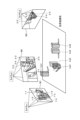
- FIG. 25 is a diagram for explaining an example of a person tracking result.
- image M1 is an image captured by camera c1.
- the image M2 is an image captured by the camera c2.
- the image M3 is an image captured by the camera c3. Based on the position of the same person in each image frame included in the images M1 to M3 and the parameters of the cameras c1 to c3, by repeating the process of calculating the position of the person in three dimensions (world coordinate system), 3 Follow a dimensional person.
- the person 1-1 in the image M1 and the person 2-1 in the image M2 are the same person, and the three-dimensional tracking result of this person is the trajectory tra1.
- the person 1-2 in the image M1, the person 2-2 in the image M2, and the person 3-2 in the image M3 are the same person, and the three-dimensional tracking result of this person is the trajectory tra2.
- the person 1-3 in the image M1, the person 2-3 in the image M2, and the person 3-3 in the image M3 are the same person, and the three-dimensional tracking result of this person is the trajectory tra3.
- the person 1-4 in the image M1, the person 2-4 in the image M2, and the person 3-4 in the image M3 are the same person, and the three-dimensional tracking result of this person is the trajectory tra4.
- the person 1-5 in the image M1, the person 2-5 in the image M2, and the person 3-5 in the image M3 are the same person, and the three-dimensional tracking result of this person is the trajectory tra5.
- FIG. 26 is a diagram for explaining prior art 1.
- FIG. A device that implements the prior art 1 is referred to as a conventional device 10 .
- the conventional device 10 has a single MOT (Multiple Object Tracking) 11 , a three-dimensional trajectory calculation section 12 and an association processing section 13 .
- MOT Multiple Object Tracking
- the single MOT 11 Upon receiving the two-dimensional area information 1a, 1b, 1c (other two-dimensional area information), the single MOT 11 generates two-dimensional locus information 2a, 2b, 2c (other two-dimensional locus information).
- the two-dimensional area information 1a is the two-dimensional coordinates (2d bboxes) of the person's area extracted from the video (successive image frames) captured by the camera c1.
- the two-dimensional area information 1b is the two-dimensional coordinates of the person's area extracted from the image captured by the camera c2.
- the two-dimensional area information 1c is the two-dimensional coordinates of the person's area extracted from the image captured by the camera c3.
- the two-dimensional trajectory information 2a is trajectory information calculated by following the continuous two-dimensional area information 1a.
- the two-dimensional trajectory information 2b is trajectory information calculated by following the continuous two-dimensional area information 1b.
- the two-dimensional trajectory information 2c is trajectory information calculated by following the continuous two-dimensional area information 1c.
- the three-dimensional trajectory calculation unit 12 Upon receiving the two-dimensional trajectory information 2a, 2b, 2c (other two-dimensional trajectory information), the three-dimensional trajectory calculation unit 12 calculates the three-dimensional trajectory information 3a, 3b, 3c ( other three-dimensional trajectory information).
- the three-dimensional trajectory calculation unit 12 calculates the three-dimensional trajectory information 3a based on the two-dimensional trajectory information 2a.
- the three-dimensional trajectory calculator 12 calculates three-dimensional trajectory information 3b based on the two-dimensional trajectory information 2b.
- the three-dimensional trajectory calculator 12 calculates three-dimensional trajectory information 3c based on the two-dimensional trajectory information 2c.
- the association processing unit 13 performs association based on the three-dimensional trajectory information 3a, 3b, 3c (other three-dimensional trajectory information) and generates the three-dimensional trajectory information 4. For example, the association processing unit 13 calculates the Eugrid distance of each locus from the three-dimensional locus information 3a, 3b, and 3c, and associates the three-dimensional locus information 3a, 3b, and 3c based on the Eugrid distance, 3D trajectory information 4 is generated.
- the conventional device 10 tracks the position of the person in three dimensions by repeatedly executing the above process.
- FIG. 27 is a diagram for explaining conventional technique 2.
- FIG. A device that implements the prior art 2 is referred to as a conventional device 20 .
- the conventional device 20 has an association processing unit 21 and an MOT 22 .
- the association processing unit 21 generates three-dimensional posture information 6 based on the two-dimensional posture information 5a, 5b, and 5c (other two-dimensional posture information).
- the two-dimensional posture information 5a is information of a person's posture extracted from video (continuous image frames) captured by the camera c1, and includes information such as joint positions.
- the two-dimensional posture information 5b is information on the posture of the person extracted from the video captured by the camera c2, and includes information such as joint positions of the person.
- the two-dimensional posture information 5c is information on the posture of the person extracted from the video captured by the camera c3, and includes information such as joint positions.
- the association processing unit 21 calculates the two-dimensional posture information 5a, 5b based on the distance, similarity, etc. between the epipolar line and the person specified from the two-dimensional posture information 5a, 5b, 5c (other two-dimensional posture information). , 5c are associated to generate three-dimensional posture information 6.
- FIG. The three-dimensional posture information 6 is three-dimensional posture information of a person, and includes information such as joint positions of the person.
- the MOT 22 generates three-dimensional trajectory information 7 based on the three-dimensional posture information 6.
- the three-dimensional trajectory information 7 is information on a three-dimensional human trajectory.
- the conventional device 20 tracks the position of the person in three dimensions by repeatedly executing the above process.
- FIG. 28 is a diagram for explaining the problem of the conventional technology.
- the 3 Compute the dimensional coordinates For example, the three-dimensional coordinates of the person P1 are calculated from the area A1 of the person included in the image Im1 of the camera c1. Also, the three-dimensional coordinates of the person P1 are calculated from the area A2 of the person included in the image Im2 of the camera c2.
- the Z-axis coordinates of the feet of the person P1 do not become 0 (Z ⁇ 0), so the three-dimensional coordinates of the person P1 cannot be calculated with high accuracy. and fail to follow.
- an object of the present invention is to provide a tracking program, a tracking method, and an information processing apparatus that can accurately track a person's three-dimensional position.
- the computer executes the following processing.
- the computer identifies a person's head region from a plurality of images captured by each of the plurality of cameras.
- the computer identifies a set of head regions corresponding to the same person based on the positions of the head regions identified from the plurality of images.
- the computer identifies the three-dimensional position of the person's head based on the two-dimensional positions of the set of head regions of the same person and the parameters set for each of the plurality of cameras.
- a person's 3D coordinates can be tracked.
- FIG. 1 is a diagram showing an example of a system according to the first embodiment.
- FIG. 2 is a diagram illustrating a configuration example of an information processing apparatus according to the first embodiment.
- FIG. 3 is a diagram illustrating an example of the data structure of a video DB.
- FIG. 4 is a diagram showing an example of the detection result of the head region.
- FIG. 5 is a diagram for explaining an example of single MOT processing.
- FIG. 6 is a diagram for explaining the processing of the first interpolation unit.
- FIG. 7 is a diagram (1) for explaining the processing of the association processing unit;
- FIG. 8 is a diagram (2) for explaining the processing of the association processing unit.
- FIG. 9 is a diagram (3) for explaining the processing of the association processing unit;
- FIG. 10 is a diagram (4) for explaining the processing of the association processing unit;
- FIG. 11 is a diagram (1) for explaining the processing of the calculation processing unit;
- FIG. 12 is a diagram (2) for explaining the processing of the calculation processing unit;
- FIG. 13 is a diagram for explaining the processing of the second interpolation unit;
- FIG. 14 is a flow chart showing the processing procedure of the information processing apparatus according to the first embodiment.
- FIG. 15 is a diagram illustrating an example of a system according to the second embodiment.
- FIG. 16 is a diagram for explaining processing of the information processing apparatus according to the second embodiment.
- FIG. 17 is a diagram showing the result of association according to the prior art.
- FIG. 18 is a diagram showing an example of an association error in the prior art.
- FIG. 19 is a diagram (1) showing the result of association by the information processing apparatus of the second embodiment.
- FIG. 20 is a diagram (2) showing the result of association by the information processing apparatus of the second embodiment.
- FIG. 21 is a diagram illustrating a configuration example of an information processing apparatus according to the second embodiment.
- FIG. 22 is a diagram for explaining the processing of the association processing unit 250 according to the second embodiment.
- FIG. 23 is a flow chart showing the processing procedure of the information processing apparatus according to the second embodiment.
- FIG. 24 is a diagram illustrating an example of a hardware configuration of a computer that implements functions similar to those of the information processing apparatus of the embodiment.
- FIG. 25 is a diagram for explaining an example of a person tracking result.
- FIG. 26 is a diagram for explaining Conventional Technique 1.
- FIG. FIG. 27 is a diagram for explaining conventional technique 2.
- FIG. FIG. 28 is a diagram for explaining the problem of the prior art.
- FIG. 1 is a diagram showing an example of a system according to the first embodiment. As shown in FIG. 1, this system has a plurality of cameras c1, c2, c3, a data acquisition device 60, and an information processing device 100. FIG. The cameras c1-c3 and the data acquisition device 60 are interconnected via a network 50. FIG. Although cameras c1 to c3 are shown in FIG. 1, the system according to the first embodiment may further include other cameras.
- Cameras c1 to c3 are cameras that capture images inside convenience stores, supermarkets, and the like.
- the cameras c 1 to c 3 transmit video data to the data acquisition device 60 .
- video data is referred to as "video data”.
- the cameras c1 to c3 are simply referred to as “cameras” when they are not distinguished from each other.
- Video data includes multiple image frames in time series.
- a frame number is assigned to each image frame in ascending chronological order.
- One image frame is a still image captured by a camera at a certain timing.
- the data acquisition device 60 receives video data from the cameras c1 to c3 and registers the received video data in a video DB (Data Base) 65.
- the video DB 65 is set in the information processing apparatus 100 by the user or the like. In the first embodiment, the information processing apparatus 100 is assumed to be offline as an example. may be sent to
- the information processing device 100 is a device that generates 3D trajectory information by following a person in 3D based on each image frame (video data) registered in the video DB 65 .
- the information processing apparatus 100 identifies the region of the person's head and the epipolar line from each image frame registered in the video DB 65 .
- the area of the person's head is referred to as a "head area”.
- the information processing apparatus 100 identifies a set of head regions corresponding to the same person based on the head region, the epipolar line, and the distance identified from each image frame, and based on the set of identified head regions, Calculate the three-dimensional coordinates of the person's head.
- the information processing apparatus 100 generates three-dimensional trajectory information regarding the person's head region by repeatedly executing such processing.
- Cameras are usually installed in high places, so even if multiple people are crowded together, the head area is less susceptible to occlusion, and most cameras can capture multiple people's head areas. is. Therefore, compared with the case of using the area information of the whole body of the person as in the conventional technology, the head area is less likely to be lost, and the position of the person (the position of the head area) can be stably tracked. be able to.
- the information processing apparatus 100 extracts only the head region, the calculation cost can be reduced and the processing speed can be increased compared to the case of specifying the region information and posture of the whole body of the person as in the conventional technology. can be done.
- the information processing apparatus 100 identifies a set of head regions corresponding to the same person based on the head regions, epipolar lines, and distances of the persons identified from each image frame. Therefore, it is possible to prevent the head regions of different persons from being identified as the same set, and to accurately track the three-dimensional position of the person.
- FIG. 2 is a diagram illustrating a configuration example of an information processing apparatus according to the first embodiment.
- the information processing apparatus 100 includes a video DB 65, a head region specifying unit 110, a single MOT 111, a first interpolation unit 112, an association processing unit 113, a calculation processing unit 114, a second and an interpolation unit 115 .
- the head region identification unit 110, single MOT 111, first interpolation unit 112, association processing unit 113, calculation processing unit 114, and second interpolation unit 115 are implemented by a control unit such as a CPU.
- the head region specifying unit 110 is an example of a first specifying unit.
- the association processing unit 113 is an example of a second specifying unit.
- the calculation processing unit 114 is an example of a third specifying unit.
- the video DB 65 is a DB that stores video data captured by cameras c1, c2, c3, and the like.
- FIG. 3 is a diagram illustrating an example of the data structure of a video DB.
- the video DB 65 stores camera identification information and video data in association with each other.
- Camera identification information is information that uniquely identifies a camera.
- cam1 indicates camera c1.
- cam2 indicates camera c2.
- cam3 indicates camera c3.
- the video data is video data captured by the corresponding camera.
- the video data includes time-series image frames and is given a frame number.
- the head region identifying unit 110 identifies the head region of the person by analyzing each image frame captured by each camera registered in the video DB 65, and sets the two-dimensional coordinates of the head region of the person. Dimensional region information 8a, 8b, 8c is output.
- the head region identifying unit 110 uses a machine-learned detection model.
- the detection model is a machine learning model that detects the head region of a person included in the image frames when time-series image frames included in the video data are input. A person detected from an image frame is assigned a person ID for identifying the person.
- the detection model is realized by an open source machine learning model or the like.
- FIG. 4 is a diagram showing an example of the detection result of the head region.
- head areas HA1a, HA1b, HA1c, HA1d, and HA1e of each person are detected from an image frame frame1 captured by a certain camera.
- the head region specifying unit 110 sets two-dimensional coordinates (2d bboxes) of the head regions HA1a to HA1e of each person, person IDs, etc., and generates two-dimensional region information.
- the head area specifying unit 110 generates two-dimensional area information 8a based on each image frame captured by the camera c1 and outputs it to the single MOT111.
- the head region specifying unit 110 generates two-dimensional region information 8b based on each image frame captured by the camera c2, and outputs it to the single MOT 111.
- the head area specifying unit 110 generates the two-dimensional area information 8c based on each image frame captured by the camera c3 and outputs it to the single MOT111.
- the head region specifying unit 110 may further generate two-dimensional region information based on each image frame captured by another camera.
- the single MOT 111 Upon receiving the two-dimensional area information 8a, 8b, 8c, the single MOT 111 generates two-dimensional trajectory information 9a, 9b, 9c. Single MOT 111 outputs two-dimensional trajectory information 9 a , 9 b , 9 c to first interpolation section 112 .
- FIG. 5 is a diagram for explaining an example of single MOT processing.
- Image frames frame k-1, frame k, and frame k+1 shown in FIG. 5 are consecutive image frames captured by the same camera and correspond to two-dimensional area information specified from each image frame.
- An image frame frame k-1 includes head areas HA1a, HA1b, and HA1c.
- the image frame frame k includes head areas HA2a, HA2b, and HA2c.
- the image frame frame k includes head areas HA3a, HA3b, and HA3c.
- the single MOT 111 identifies the head region of the same person based on the distance of the head region in each image frame.
- the single MOT 111 links the head areas HA1a, HA2a, and HA3a, respectively.
- the single MOT 111 links the head areas HA1b, HA2b, and HA3b, assuming that the head areas HA1b, HA2b, and HA3b are the head areas of the same person.
- the single MOT 111 links the head areas HA1a, HA2a, and HA3a, respectively.
- the single MOT 111 generates two-dimensional trajectory information from each two-dimensional area information corresponding to each image frame captured by the same camera by executing the processing shown in FIG.
- the single MOT 111 uses the technology described in the non-patent document (Ramana Sundararaman et al "Tracking Pedestrian Heads in Dense Crowd” arXiv:2103.13516v1 [cs.CV] 24 Mar 2021) to obtain each two-dimensional area information , two-dimensional trajectory information can be generated.
- the first interpolating unit 112 receives the two-dimensional trajectory information 9a to 9c, and interpolates the head region using the information on the preceding and succeeding head regions when there is a gap or the like in the head region in a certain image frame.
- the first interpolator 112 outputs the interpolated two-dimensional trajectory information 9 a to 9 c to the association processor 113 .
- FIG. 6 is a diagram for explaining the processing of the first interpolation unit.
- the head region is not detected in the image frame frame k before interpolation.
- the head areas HA1a, HA1b, and HA1c are detected in the image frame frame k-1 before interpolation.
- Head areas HA3a, HA3b, and HA3c are detected in the image frame frame k+1 before interpolation.
- the first interpolation unit 112 calculates the head region of the image frame frame k Interpolate HA2a. Based on the two-dimensional coordinates of the head region HA1b of the image frame frame k-1 and the two-dimensional coordinates of the head region HA3b of the image frame frame k+1, the first interpolation unit 112 calculates the head region of the image frame frame k. Interpolate HA2b.
- the first interpolation unit 112 calculates the head region of the image frame frame k. Interpolate HA2c.
- the head areas HA2a, HA2b, and HA2c of the image frame frame k are set after interpolation.
- the association processing unit 113 Based on the two-dimensional trajectory information 9a to 9c, the association processing unit 113 associates head areas corresponding to the same person with respect to head areas between image frames captured by different cameras. 7 to 10 are diagrams for explaining the processing of the association processing unit.
- FIG. 7 will be described.
- the image frame 10-1 is an image frame included in video data captured by the camera c1.
- Image frame 10-1 includes a person's head area HA10. Assume that the height of the head area HA10 is “h 1 ” and the width is “w 1 ”.
- the image frame 10-2 is an image frame included in the video data shot by the camera c2.
- Image frame 10-2 includes a person's head area HA11. Assume that the height of the head area HA10 is “h 2 " and the width is "w 2 ".
- the image frame 10-1 and the image frame 10-2 are assumed to be image frames shot at the same timing. For example, let the frame number of the image frame 10-1 and the frame number of the image frame 10-2 be the same.
- the association processing unit 113 identifies the epipolar line l(x 2 , 0) on the image frame Im10-1 based on the parameters of the cameras c1 and c2 and the central coordinate x2 of the head area HA11. This means that the center coordinate x 2 of the head region HA11 is included on the epipolar line l(x 2 , 0).
- the association processing unit 113 calculates the distance d(l(x 2 ), x 1 ) between the central coordinate x 1 of the head region HA10 and the epipolar line l(x 2 ) on the image frame Im10-1.
- the association processing unit 113 divides the distance d(l(x 2 ), x 1 ) by ((w 1 +h 1 )/2) to adjust the scale, and divides the head region HA10 and the head region HA11. Calculate the epipolar distance.
- the association processing unit 113 identifies the epipolar line l(x 1 ) on the image frame Im10-2 based on the parameters of the cameras c1 and c2 and the central coordinate x 1 of the head region HA10. This means that the central coordinate x 1 of the head region HA10 is included on the epipolar line l(x 1 ).
- the association processing unit 113 divides the distance d(l(x 1 ), x 2 ) by ((w 2 +h 2 )/2) to adjust the scale, and divides the head region HA10 and the head region HA11. Calculate the epipolar distance.
- the association processing unit 113 executes the above processing for each head region included in image frames captured by different cameras, and calculates the epipolar distance of each head region.
- Fig. 8 the epipolar distances for each head region are indicated by the matrix MA.
- head areas HA10-1 and HA11-1 are the head areas of a person in the image frame captured by camera c1.
- the head areas HA10-2 and HA11-2 are the head areas of the person in the image frame captured by the camera c2.
- the epipolar distance for the same head region will be "0.0".
- the association processing unit 113 scans the epipolar distances set in the matrix MA in the vertical direction, and identifies the minimum epipolar distance among the epipolar distances excluding the epipolar distance "0.0" corresponding to the same image, Based on the identification result, a set of head regions corresponding to the same person is identified.
- the minimum epipolar distance among the epipolar distances other than the epipolar distance "0.0" is referred to as "minimum epipolar distance”.
- the association processing unit 113 associates the set of the head area HA10-1 and the head area HA10-2 as the head area of the same person.
- the minimum epipolar distance is the epipolar distance "0.1" obtained from the pair of the head regions HA11-1 and HA11-2. Therefore, the association processing unit 113 associates the set of the head area HA11-1 and the head area HA11-2 as the head area of the same person.
- the association processing unit 113 identifies a set of head regions corresponding to the same person by repeatedly executing the above processing for each head region included in each image frame of the two-dimensional trajectory information 9a to 9c.
- image frame Im20-1 is an image frame captured by camera c1.
- Human head areas HA1a, HA1b, and HA1c are identified from the image frame Im20-1.
- An image frame Im20-2 is an image frame captured by the camera c2.
- the person's head areas HA1x, HA1y, and HA1z are identified from the image frame Im20-2.
- the epipolar line l1a corresponding to the head area HA1a is identified.
- epipolar line l1b corresponding to head region HA1b is identified.
- epipolar line l1c corresponding to head region HA1c is identified.
- the association processing unit 113 calculates the above epipolar distance and associates the head regions of the same person. For example, the association processing unit 113 associates the head area HA1a and the head area HA1x as the same person's head area. The association processing unit 113 associates the head area HA1b and the head area HA1y as the head area of the same person. The association processing unit 113 associates the head area HA1c and the head area HA1z as the head area of the same person.
- An image frame Im21-1 is an image frame captured by the camera c1. Human head areas HA2a, HA2b, and HA2c are identified from the image frame Im21-1.
- An image frame Im21-2 is an image frame captured by the camera c2. Human head areas HA2x, HA2y, and HA2z are identified from the image frame Im21-2.
- an epipolar line l2a corresponding to the head area HA2a is specified.
- an epipolar line l2b corresponding to the head area HA2b is specified.
- an epipolar line l2c corresponding to the head area HA2c is identified.
- the association processing unit 113 calculates the above epipolar distance and associates the head regions of the same person. For example, the association processing unit 113 associates the head area HA2a and the head area HA2x as the same person's head area. The association processing unit 113 associates the head area HA2b and the head area HA2y as the head area of the same person. The association processing unit 113 associates the head area HA2c and the head area HA2z as the head area of the same person.
- An image frame Im22-1 is an image frame captured by the camera c1. Human head areas HA3a, HA3b, and HA3c are identified from the image frame Im22-1.
- An image frame Im22-2 is an image frame captured by the camera c2. Human head areas HA3x, HA3y, and HA3z are identified from the image frame Im22-2.
- an epipolar line l3a corresponding to the head area HA3a is specified.
- epipolar line l3b corresponding to head region HA3b is identified.
- epipolar line l3c corresponding to head region HA3c is identified.
- the association processing unit 113 creates matrices MA1, MA2, and MA3 for each of frames k ⁇ 1, k, and k+1 in the same manner as the processing described with reference to FIG. Associate.
- FIG. 10 will be described using matrices MA1, MA2, and MA3 based on successive image frames.
- Matrix MA1 is specified based on the image frame with frame number “k ⁇ 1”.
- Matrix MA2 is identified based on the image frame with frame number “k”.
- Matrix MA3 is specified based on the image frame with frame number “k+1”.
- the matrix MA1 will be explained.
- the head areas HA10-1 and HA11-1 are the head areas of the person in the image frame captured by the camera c1.
- the head areas HA10-2 and HA11-2 are the head areas of the person in the image frame captured by the camera c2.
- the association processing unit 113 determines that the minimum epipolar distance in the 0th row of the matrix MA1 is the epipolar distance "0.2" obtained from the pair of the head regions HA10-1 and HA10-2. Therefore, the association processing unit 113 associates the set of the head area HA10-1 and the head area HA10-2 as the head area of the same person.
- the association processing unit 113 determines that the minimum epipolar distance in the first row of the matrix MA1 is the epipolar distance "0.1" obtained from the pair of the head regions HA11-1 and HA11-2. Therefore, the association processing unit 113 associates the set of the head area HA11-1 and the head area HA11-2 as the head area of the same person.
- the matrix MA2 will be explained.
- the head areas HA12-1 and HA13-1 are the head areas of the person in the image frame captured by the camera c1.
- the head areas HA12-2 and HA13-2 are the head areas of the person in the image frame captured by the camera c2.
- the association processing unit 113 determines that the minimum epipolar distance in the 0th row of the matrix MA2 is the epipolar distance "0.1" obtained from the pair of the head regions HA12-1 and HA12-2. Association processing unit 113 determines that the minimum epipolar distance in the first row of matrix MA2 is the epipolar distance “0.2” obtained from the combination of head regions HA13-1 and HA13-2. The association processing unit 113 associates the set of the head area HA12-1 and the head area HA12-2, the set of the head area HA12-2 and the head area HA12-3, and the head area of the same person.
- the matrix MA3 will be explained.
- the head areas HA14-1 and HA15-1 are the head areas of the person in the image frame captured by the camera c1.
- the head areas HA14-2 and HA15-2 are the head areas of the person in the image frame captured by the camera c2.
- the association processing unit 113 determines that the minimum epipolar distance in the 0th row of the matrix MA3 is the epipolar distance "0.2" obtained from the pair of the head regions HA14-1 and HA14-2. Therefore, the association processing unit 113 associates the set of the head area HA14-1 and the head area HA14-2 as the head area of the same person.
- the association processing unit 113 determines that the minimum epipolar distance in the first row of the matrix MA3 is the epipolar distance "0.3" obtained from the pair of the head regions HA15-1 and HA15-2. Therefore, the association processing unit 113 associates the set of the head area HA15-1 and the head area HA15-2 as the head area of the same person.
- the association processing unit 113 performs the processing described with reference to FIGS. 7 to 10 to associate the same head region between image frames captured by different cameras based on the two-dimensional trajectory information 9a to 9c. associated with the corresponding head regions of the person.
- the association processing unit 113 outputs information on the associated head region to the calculation processing unit 114 .
- the calculation processing unit 114 uses camera parameters and triangulation to calculate the three-dimensional coordinates of the person's head region from the associated two-dimensional coordinates of the head region.
- 11 and 12 are diagrams for explaining the processing of the calculation processing unit.
- Image frame Im19-1 is an image frame captured by camera c1.
- the person's head areas HA1a and HA1b are identified from the image frame Im19-1.
- the person's head areas HA1x and HA1y are identified from the image frame Im19-2.
- the head area HA1a and the head area HA1x are associated by the processing of the association processing unit 113 described above.
- the head area HA1b and the head area HA1y are associated.
- the calculation processing unit 114 calculates the three-dimensional coordinates of the head of the person P1 by triangulation based on the two-dimensional coordinates of the head region HA1a and the two-dimensional coordinates of the head region HA1x.
- the calculation processing unit 114 calculates the three-dimensional coordinates of the head of the person P2 by triangulation based on the two-dimensional coordinates of the head region HA1b and the two-dimensional coordinates of the head region HA1y.
- the calculation processing unit repeatedly executes the above processing for the image frame of each frame number.
- image frame Im20-1 is an image frame captured by camera c1.
- Human head areas HA1a, HA1b, and HA1c are identified from the image frame Im20-1.
- the person's head areas HA1x, HA1y, and HA1z are identified from the image frame Im20-2.
- the head region HA1a and the head region HA1x are associated by the processing of the association processing unit 113 .
- the head area HA1b and the head area HA1y are associated.
- the head region HA1c and the head region HA1z are associated.
- the calculation processing unit 114 calculates the three-dimensional coordinates of the person P1 by triangulation based on the two-dimensional coordinates of the head area HA1a and the two-dimensional coordinates of the head area HA1x.
- Calculation processing unit 114 calculates the three-dimensional coordinates of person P2 by triangulation based on the two-dimensional coordinates of head region HA1b and the two-dimensional coordinates of head region HA1y.
- the calculation processing unit 114 calculates the three-dimensional coordinates of the person P3 by triangulation based on the two-dimensional coordinates of the head region HA1c and the two-dimensional coordinates of the head region HA1z.
- image frame Im21-1 is an image frame captured by camera c1.
- Human head areas HA2a, HA2b, and HA2c are identified from the image frame Im21-1.
- Human head areas HA2x, HA2y, and HA2z are identified from the image frame Im21-2.
- the head region HA2a and the head region HA2x are associated by the processing of the association processing unit 113 .
- the head region HA2b and the head region HA2y are associated.
- the head region HA2c and the head region HA2z are associated.
- the calculation processing unit 114 calculates the three-dimensional coordinates of the person P1 by triangulation based on the two-dimensional coordinates of the head area HA2a and the two-dimensional coordinates of the head area HA2x.
- the calculation processing unit 114 calculates the three-dimensional coordinates of the person P2 by triangulation based on the two-dimensional coordinates of the head region HA2b and the two-dimensional coordinates of the head region HA2y.
- the calculation processing unit 114 calculates the three-dimensional coordinates of the person P3 by triangulation based on the two-dimensional coordinates of the head region HA2c and the two-dimensional coordinates of the head region HA2z.
- image frame Im22-1 is an image frame captured by camera c1.
- Human head areas HA3a, HA3b, and HA3c are identified from the image frame Im22-1.
- Human head areas HA3x, HA3y, and HA3z are identified from the image frame Im22-2.
- the head region HA3a and the head region HA3x are associated by the processing of the association processing unit 113.
- FIG. Assume that the head region HA3b and the head region HA3y are associated.
- the head region HA3c and the head region HA3z are associated.
- the calculation processing unit 114 calculates the three-dimensional coordinates of the person P1 by triangulation based on the two-dimensional coordinates of the head area HA3a and the two-dimensional coordinates of the head area HA3x.
- the calculation processing unit 114 calculates the three-dimensional coordinates of the person P2 by triangulation based on the two-dimensional coordinates of the head region HA3b and the two-dimensional coordinates of the head region HA3y.
- the calculation processing unit 114 calculates the three-dimensional coordinates of the person P3 by triangulation based on the two-dimensional coordinates of the head region HA3c and the two-dimensional coordinates of the head region HA3z.
- the calculation processing unit 114 executes the above process, the three-dimensional coordinate loci (three-dimensional locus information 15) of the head regions of the persons P1, P2, and P3 are calculated from the image frame numbers of the respective frame numbers.
- Calculation processing section 114 outputs three-dimensional trajectory information 15 to second interpolation section 115 .
- the second interpolating unit 115 receives the three-dimensional trajectory information 15, and if there is a gap in the three-dimensional coordinates of the head region in a certain image frame, using information on the three-dimensional coordinates of the front and rear head regions, Interpolate the head region.
- the second interpolator 115 outputs interpolated three-dimensional trajectory information 15 .
- FIG. 13 is a diagram for explaining the processing of the second interpolation unit.
- the three-dimensional coordinates of the person P1 are specified at the frame number k ⁇ 1, the three-dimensional coordinates of the person P1 are not specified at the frame number k, and the frame At number k+1, the three-dimensional coordinates of person P1 are identified.
- the second interpolation unit 115 calculates the coordinates between the three-dimensional coordinates of the person P1 in the frame number k ⁇ 1 and the three-dimensional coordinates of the person P1 in the frame number k+1 as the three-dimensional coordinates of the person P1 in the frame number k. Interpolation is performed by
- FIG. 14 is a flow chart showing the processing procedure of the information processing apparatus according to the first embodiment.
- the head region specifying unit 110 of the information processing device 100 acquires each image frame captured by each camera from the video DB 65 (step S101).
- the head region identifying unit 110 identifies a person's head region from the image frame and generates two-dimensional region information (step S102).
- the single MOT 111 of the information processing device 100 generates two-dimensional trajectory information based on the two-dimensional area information (step S103).
- the first interpolation unit 112 of the information processing apparatus 100 performs interpolation processing on the two-dimensional trajectory information when there is a head region to be interpolated (step S104).
- the association processing unit 113 of the information processing device 100 calculates the epipolar distance based on the two-dimensional trajectory information, and associates the head regions corresponding to the same person (step S105).
- the calculation processing unit 114 of the information processing apparatus 100 generates three-dimensional trajectory information based on triangulation based on the two-dimensional coordinates of the set of head regions corresponding to the same person (step S106).
- the second interpolation unit 115 of the information processing device 100 performs interpolation processing on the three-dimensional trajectory information when there is a head region to be interpolated (step S107).
- the information processing device 100 outputs the three-dimensional trajectory information (step S108).
- the information processing apparatus 100 identifies a set of head regions corresponding to the same person based on the head region, the epipolar line, and the distance identified from each image frame, and based on the set of identified head regions, Calculate the three-dimensional coordinates of the person's head.
- the information processing apparatus 100 generates three-dimensional trajectory information regarding the person's head region by repeatedly executing such processing.
- the information processing apparatus 100 Since the camera is installed at a high place, the head area is not affected by occlusion even if multiple people are crowded, and most cameras can capture the head area of multiple people. . Since the information processing apparatus 100 identifies the head region of the person, the head region is less likely to be lost than in the case of using the region information of the whole body of the person as in the conventional technology. A person's position (head region position) can be tracked. In addition, since the information processing apparatus 100 extracts only the head region, the calculation cost can be reduced and the processing speed can be increased compared to the case of specifying the region information and posture of the whole body of the person as in the conventional technology. can be done.
- the information processing apparatus 100 identifies a set of head regions corresponding to the same person based on the head region, epipolar line, and distance of the person identified from each image frame. Therefore, it is possible to prevent the head regions of different persons from being identified as the same set, and to accurately track the three-dimensional position of the person.
- the information processing apparatus 100 adjusts the scale of the epipolar distance based on the size of the head region included in each image frame. As a result, even if the distance between the person and each camera is different, the head regions corresponding to the same person can be appropriately associated.
- FIG. 15 is a diagram showing an example of a system according to the second embodiment. As shown in FIG. 15, this system has a plurality of cameras c1, c2, c3 and an information processing device 200. In FIG. The cameras c1 to c3 and the information processing device 200 are interconnected via a network 50. FIG. Although cameras c1 to c3 are shown in FIG. 15, the system according to the second embodiment may further include other cameras.
- Cameras c1 to c3 are cameras that capture images inside convenience stores, supermarkets, and the like. Cameras c1 to c3 transmit video data to information processing device 200 .
- the information processing apparatus 200 receives video data from the cameras c1 to c3 online, and outputs three-dimensional trajectory information.
- the information processing device 200 can also register the received video data in the video DB 65 .
- the information processing device 200 sequentially acquires image frames from the cameras c1 to c3, and calculates three-dimensional trajectory information for each preset window (sliding window).
- the information processing apparatus 200 associates the 3D trajectory information of each window to generate the 3D trajectory information of the person.
- FIG. 16 is a diagram for explaining the processing of the information processing apparatus according to the second embodiment.
- the information processing device 200 sets a window w1, a window w2, and a window w3.
- windows w1 to w3 are used for explanation, but windows w4 and w5 subsequent to window w3 are also included.
- n 60.
- the information processing device 200 divides the image frame into a plurality of short section windows.
- the information processing apparatus 200 executes the processing corresponding to the single MOT 111, the first interpolation unit 112, the association processing unit 113, the calculation processing unit 114, and the second interpolation unit 115 described in the first embodiment on the image frames in the short section. and generate three-dimensional trajectory information for each short section.
- the information processing apparatus 200 generates three-dimensional trajectory information (w1) by integrating three-dimensional trajectory information for each short section of window w1.
- the information processing device 200 generates three-dimensional trajectory information (w2) and three-dimensional trajectory information (w3) by executing processing similar to that for window w1 for windows w2 and w3.
- the information processing device 200 inputs the three-dimensional trajectory information (w1) and the three-dimensional trajectory information (w2) to the association processing unit 250-1.
- the association processing unit 250-1 generates three-dimensional trajectory information (w1&w2) by associating the three-dimensional trajectory information (w1) and the three-dimensional trajectory information (w2), and performs the association processing on the three-dimensional trajectory information (w1&w2). Output to section 250-2.
- the information processing device 200 inputs the three-dimensional trajectory information (w3) to the association processing unit 250-2.
- the association processing unit 250-2 generates three-dimensional trajectory information (w1&w2&w3) that associates the three-dimensional trajectory information (w1&w2) with the three-dimensional trajectory information (w3), and associates the three-dimensional trajectory information (w1&w2) with the subsequent association. Output to the processing unit.
- each association processing unit of the information processing device 200 By each association processing unit of the information processing device 200 repeatedly executing the above processing, information that associates the three-dimensional trajectory of each window is generated.
- the system of the conventional device 20 is a system (Single-frame Multi-view Data Association system) in which regions of the same person included in one image frame captured by each camera are associated with each other.
- FIG. 17 is a diagram showing the result of association by the conventional technology.
- image frame Im30-1 is an image captured by camera c1. Human areas A1-1, A1-2, A1-3, and A1-4 are detected from the image frame Im30-1.
- An image frame Im30-2 is an image captured by the camera c2. Human areas A2-1 and A2-2 are detected from the image frame Im30-2.
- Image frame Im30-3 is an image captured by camera c3.
- a human area A3-1 is detected from the image frame Im30-3.
- k be the frame number of image frames Im30-1, Im30-2, and Im30-3.
- the areas A1-1, A2-1, and A3-1 are associated with each other by the Single-frame Multi-view Data Association method.
- the conventional apparatus 20 if the above association is repeatedly executed for each image frame of each frame number, an error may occur in the association.
- FIG. 18 is a diagram showing an example of an association error in the prior art.
- the image frames Im40-1, Im40-2, Im40-3, Im40-4 and Im40-5 have the same frame number.
- An image frame Im40-1 is an image captured by the camera c1. Human areas A1-0, A1-1, A1-2, A1-3, A1-4, and A1-7 are detected from the image frame Im40-1.
- An image frame Im40-2 is an image captured by the camera c2. Human areas A2-0, A2-1, and A2-2 are detected from the image frame Im40-2.
- An image frame Im40-3 is an image captured by the camera c3. Human areas A3-0, A3-1, A3-2, A3-3, A3-4, A3-5, and A3-7 are detected from the image frame Im40-3.
- An image frame Im40-4 is an image captured by the camera c4. Human areas A4-0, A4-1, A4-2, A4-3, and A4-6 are detected from the image frame Im40-4.
- An image frame Im40-5 is an image captured by the camera c5. Human areas A5-0, A5-1, A5-2, A5-3, A5-4, and A5-5 are detected from the image frame Im40-5.
- areas A1-0, A2-0, A3-0, A4-0, and A5-0 are associated with each other.
- Areas A1-1, A2-1, A3-1, A4-1 and A5-1 are associated with each other.
- Areas A1-2, A2-2, A3-2, A4-2 and A5-2 are associated with each other.
- Areas A1-3, A3-3, A4-3 and A5-3 are associated with each other.
- Areas A1-4, A3-4 and A5-4 are associated with each other.
- Areas A3-5 and A5-5 are associated with each other.
- Areas A4-6 and A5-6 are associated with each other.
- an error occurs in associating areas A1-4, A3-4, and A5-4.
- the correct associations are areas A1-4, A3-5 (A3-4 is wrong) and A5-5 (A5-4 is wrong).
- FIG. 19 and 20 are diagrams showing the results of association by the information processing apparatus of the second embodiment.
- FIG. 19 will be described. Let “k” be the frame number of the image frames Im35-1, Im35-2, and Im35-3. Assume that the frame numbers of image frames Im35-4, Im35-5, and Im35-6 are "k+ ⁇ ".
- An image frame Im35-1 is an image captured by the camera c1. Human head areas A1-1, A1-2, A1-3, and A1-4 are detected from the image frame Im35-1.
- An image frame Im35-2 is an image captured by the camera c2. Human head areas A2-1 and A2-2 are detected from the image frame Im35-2.
- An image frame Im35-3 is an image captured by the camera c3. A person's head region A3-1 is detected from the image frame Im35-3.
- An image frame Im35-4 is an image captured by the camera c1. Human head areas A4-1, A4-2, and A4-3 are detected from the image frame Im35-4.
- An image frame Im35-5 is an image captured by the camera c2. Human head areas A5-1, A5-2, and A5-3 are detected from the image frame Im35-2.
- An image frame Im35-6 is an image captured by the camera c3. Human head areas A6-1 and A6-2 are detected from the image frame Im35-6.
- the information processing apparatus 200 executes the processing described with reference to FIG. 16 and associates the head regions between different frame numbers, the head regions A1-1, A2-1, A3-1, A4-1, A5-1, A6-1 are associated respectively. Head regions A1-2, A2-2, A4-2, A5-2, A6-2 are associated respectively. Head regions A1-3, A4-3, A5-3 are associated with each other.
- the information processing apparatus 200 sets the window and repeats the association, thereby preventing the occurrence of the association error described with reference to FIG. 18 .
- the image frames Im45-1, Im45-2, Im45-3, Im45-4 and Im45-5 have the same frame number.
- An image frame Im45-1 is an image captured by the camera c1. Human head areas A1-1, A1-2, A1-3, A1-4, A1-5, A1-6, and A1-7 are detected from the image frame Im45-1.
- An image frame Im45-2 is an image captured by the camera c2. Human head areas A2-1, A2-2, and A2-4 are detected from the image frame Im45-2.
- An image frame Im45-3 is an image captured by the camera c3. Human head areas A3-1, A3-2, A3-3, A3-4, A3-5, A3-6, and A3-7 are detected from the image frame Im45-3.
- An image frame Im45-4 is an image taken by the camera c4. Human head areas A4-1, A4-2, A4-3, A4-4, and A4-5 are detected from the image frame Im45-4.
- An image frame Im45-5 is an image captured by the camera c5. Human head areas A5-1, A5-2, A5-3, A5-4, A5-5, A5-6 and A5-7 are detected from the image frame Im45-5.
- the regions A1-1, A2-1, A3-1, A4-1, and A5-1 are associated with each other. be done. Areas A1-2, A2-2, A3-2, A4-2 and A5-2 are associated with each other. Areas A1-3, A3-3, A4-3 and A5-3 are associated with each other. Areas A1-6, A3-6 and A5-6 are associated with each other. Areas A1-7, A3-7 and A5-7 are associated with each other.
- the associations shown in FIG. 20 are correct associations.
- the interval By setting windows to wrap and associating them, tracking accuracy can be improved.
- FIG. 21 is a diagram illustrating a configuration example of an information processing apparatus according to the second embodiment.
- the information processing apparatus 200 includes a window generation unit 65A, a head region identification unit 110, a single MOT 111, a first interpolation unit 112, an association processing unit 113, a calculation processing unit 114, and a second interpolation unit 115 .
- Information processing apparatus 200 includes communication unit 210 , window control unit 220 , and association processing unit 250 .
- the head region identification unit 110, single MOT 111, first interpolation unit 112, association processing unit 113, calculation processing unit 114, and second interpolation unit 115 are implemented by a control unit such as a CPU.
- the communication unit 210, the window control unit 220, and the association processing unit 250 are also implemented by a control unit such as a CPU.
- the head region specifying unit 110, the single MOT 111, the first interpolation unit 112, the association processing unit 113, the calculation processing unit 114, and the second interpolation unit 115 are explained in the same manner as the processing units explained in FIG. is.
- the window generator 65A generates a frame for each window from the frames received from the camera.
- the communication unit 210 receives video data from the cameras c1 to c3 (other cameras) and outputs the received video data to the window generation unit 65A.
- Window control unit 220 performs head region specifying unit 110, single MOT 111, first interpolation unit 112, association processing unit 113, calculation processing unit 114, second Processing is realized in cooperation with the interpolation unit 115 .
- the window control unit 220 generates three-dimensional trajectory information (w1, w2, . . . ) for each window, and outputs the three-dimensional trajectory information (w1, w2, . be done.
- the association processing unit 250 executes processing corresponding to the association processing units 250-1, 250-2, . . . etc. shown in FIG. For example, the association processing unit 250 generates three-dimensional trajectory information (w1&w2) that associates three-dimensional trajectory information (w1) and three-dimensional trajectory information (w2). The association processing unit 250 generates 3D trajectory information (w1&w2&w3) by associating the 3D trajectory information (w1&w2) with the 3D trajectory information (w3).
- FIG. 22 is a diagram for explaining the processing of the association processing unit 250 according to the second embodiment.
- the window w includes a three-dimensional trajectory w1-1 of the person A's head region and a three-dimensional trajectory w1-2 of the person B's head region.
- the window w+1 includes a three-dimensional trajectory w2-1 of the head region of person C, a three-dimensional trajectory w2-2 of the head region of person D, and a three-dimensional trajectory w2-3 of the head region of person E. and
- the association processing unit 250 calculates the Euclidean distances between the three-dimensional trajectory w1-1 and the three-dimensional trajectories w2-1, w2-2, and w2-3, and sets the three-dimensional trajectories whose Euclidean distances are less than the threshold. identify and make associations. For example, the three-dimensional trajectory w1-1 and the three-dimensional trajectory w2-1 are associated and integrated into one three-dimensional trajectory.
- the association processing unit 250 calculates the Euclidean distances between the three-dimensional trajectory w1-2 and the three-dimensional trajectories w2-1, w2-2, and w2-3, and sets the three-dimensional trajectories whose Euclidean distances are less than the threshold. identify and make associations. For example, the three-dimensional trajectory w1-2 and the three-dimensional trajectory w2-2 are associated and integrated into one three-dimensional trajectory.
- the association processing unit 250 calculates the Eugrid distance based on Equation (1). Also, the association processing unit 250 may associate each three-dimensional trajectory using the cost matrix shown in Equation (2) and the Boolean matrix shown in Equation (3).
- FIG. 23 is a flow chart showing the processing procedure of the information processing apparatus according to the second embodiment.
- the communication unit 210 of the information processing device 200 starts receiving video data from the camera (step S201).
- a window control unit 220 of the information processing apparatus 200 sets a window of a predetermined interval, and includes a head region specifying unit 110, a single MOT 111, a first interpolation unit 112, an association processing unit 113, a calculation processing unit 114, a In cooperation with the binary interpolation unit 115, the three-dimensional trajectory information for each window is sequentially generated (step S202).
- the association processing unit 250 of the information processing device 200 associates the three-dimensional information based on the Eugrid distance of the three-dimensional trajectory information of each window (step S203).
- the association processing unit 250 outputs the three-dimensional trajectory information (step S204).
- the information processing apparatus 200 sequentially acquires the image frames registered in the video DB 65, calculates 3D trajectory information for each window set in advance, associates the 3D trajectory information of each window, and creates a 3D image of the person. Generate trajectory information. As a result, it is possible to prevent an error in associating the head region of each image frame, and to accurately generate three-dimensional trajectory information for each person.
- FIG. 24 is a diagram illustrating an example of a hardware configuration of a computer that implements functions similar to those of the information processing apparatus of the embodiment.
- the computer 300 has a CPU 301 that executes various arithmetic processes, an input device 302 that receives data input from the user, and a display 303 .
- the computer 300 also has a communication device 304 and an interface device 305 for exchanging data with the cameras c1 to c1 (other cameras) and external devices or the like via a wired or wireless network.
- the computer 300 also has a RAM 306 that temporarily stores various information, and a hard disk device 307 . Each device 201 - 207 is then connected to a bus 208 .
- the hard disk device 307 has a head area identification program 307a, a trajectory information calculation program 307b, a window processing program 307c, and an association processing program 307d.
- the CPU 301 reads each program 307 a to 307 d and develops them in the RAM 306 .
- the head region identification program 307a functions as a head region identification process 306a.
- the trajectory information calculation program 307b functions as a trajectory information calculation process 306b.
- Windowing program 307c functions as windowing process 306c.
- the association program 307d functions as an association processing process 306d.
- the processing of the head region identification process 306a corresponds to the processing of the head region identification unit 110.
- the processing of the trajectory information calculation process 306 b corresponds to the processing of the single MOT 111 , first interpolation section 112 , association processing section 113 , calculation processing section 114 and second interpolation section 115 .
- the processing of the window processing process 306c corresponds to the processing of the window controller 220.
- FIG. The processing of the association processing process 306 d corresponds to the processing of the association processing unit 250 .
- each program does not necessarily have to be stored in the hard disk device 307 from the beginning.
- each program is stored in a “portable physical medium” such as a flexible disk (FD), CD-ROM, DVD, magneto-optical disk, IC card, etc. inserted into the computer 300 . Then, the computer 300 may read and execute each of the programs 307a-307d.
- a “portable physical medium” such as a flexible disk (FD), CD-ROM, DVD, magneto-optical disk, IC card, etc.
Landscapes
- Engineering & Computer Science (AREA)
- Multimedia (AREA)
- Computer Vision & Pattern Recognition (AREA)
- Physics & Mathematics (AREA)
- General Physics & Mathematics (AREA)
- Theoretical Computer Science (AREA)
- Image Analysis (AREA)
- Closed-Circuit Television Systems (AREA)
Abstract
情報処理装置100は、複数のカメラのそれぞれが撮影した複数の画像から、人物の頭領域をそれぞれ特定する。情報処理装置100は、複数の画像から特定した頭領域の位置を基にして、同一の人物に対応する頭領域の組を特定する。情報処理装置100は、同一の人物の頭領域の組の2次元上の位置と、複数のカメラにそれぞれ設定されたパラメータとを基にして、3次元上の人物の頭の位置を特定する。
Description
本発明は、追従プログラム等に関する。
複数のカメラによって撮影された映像を用いて、3次元上の人物の位置を追従する技術がある。図25は、人物追従結果の一例を説明するための図である。図25において、映像M1は、カメラc1よって撮影された映像である。映像M2は、カメラc2によって撮影された映像である。映像M3は、カメラc3によって撮影された映像である。映像M1~M3に含まれる各画像フレームの同一人物の位置と、カメラc1~c3のパラメータを基にして、3次元上(世界座標系)の人物の位置を算出する処理を繰り返すことで、3次元上の人物を追従する。
たとえば、映像M1の人物1-1と、映像M2の人物2-1とは同一人物であり、かかる人物の3次元上の追従結果は、軌跡tra1となる。映像M1の人物1-2と、映像M2の人物2-2と、映像M3の人物3-2とは同一人物であり、かかる人物の3次元上の追従結果は、軌跡tra2となる。
映像M1の人物1-3と、映像M2の人物2-3と、映像M3の人物3-3とは同一人物であり、かかる人物の3次元上の追従結果は、軌跡tra3となる。映像M1の人物1-4と、映像M2の人物2-4と、映像M3の人物3-4とは同一人物であり、かかる人物の3次元上の追従結果は、軌跡tra4となる。映像M1の人物1-5と、映像M2の人物2-5と、映像M3の人物3-5とは同一人物であり、かかる人物の3次元上の追従結果は、軌跡tra5となる。
ここで、複数のカメラによって撮影された映像を用いて、3次元上の人物の位置を追従する従来技術1、2について説明する。
図26は、従来技術1を説明するための図である。従来技術1を実行する装置を、従来装置10と表記する。従来装置10は、シングルMOT(Multiple Object Tracking)11と、3次元軌跡計算部12と、関連付け処理部13とを有する。
シングルMOT11は、2次元領域情報1a,1b,1c(その他の2次元領域情報)を受け付けると、2次元軌跡情報2a,2b,2c(その他の2次元軌跡情報)を生成する。
2次元領域情報1aは、カメラc1によって撮影された映像(連続する画像フレーム)から抽出される人物の領域の2次元座標(2d bboxes)である。2次元領域情報1bは、カメラc2によって撮影された映像から抽出される人物の領域の2次元座標である。2次元領域情報1cは、カメラc3によって撮影された映像から抽出される人物の領域の2次元座標である。
2次元軌跡情報2aは、連続する2次元領域情報1aを追従することで算出される軌跡情報である。2次元軌跡情報2bは、連続する2次元領域情報1bを追従することで算出される軌跡情報である。2次元軌跡情報2cは、連続する2次元領域情報1cを追従することで算出される軌跡情報である。
3次元軌跡計算部12は、2次元軌跡情報2a,2b,2c(その他の2次元軌跡情報)を受け付けると、カメラc1~c3のパラメータを基にして、3次元軌跡情報3a,3b,3c(その他の3次元軌跡情報)を計算する。3次元軌跡計算部12は、人物の足元のZ軸座標が0(Z=0)であることを仮定して、2次元の人物の軌跡から、3次元の人物の軌跡に変換する。
たとえば、3次元軌跡計算部12は、2次元軌跡情報2aを基にして、3次元軌跡情報3aを計算する。3次元軌跡計算部12は、2次元軌跡情報2bを基にして、3次元軌跡情報3bを計算する。3次元軌跡計算部12は、2次元軌跡情報2cを基にして、3次元軌跡情報3cを計算する。
関連付け処理部13は、3次元軌跡情報3a,3b,3c(その他の3次元軌跡情報)を基にして、関連付けを行い、3次元軌跡情報4を生成する。たとえば、関連付け処理部13は、3次元軌跡情報3a,3b,3cから各軌跡のユーグリッド距離等を算出し、ユーグリッド距離を基にして、3次元軌跡情報3a,3b,3cを関連付けて、3次元軌跡情報4を生成する。
従来装置10は、上記処理を繰り返し実行することで、3次元上の人物の位置を追従する。
図27は、従来技術2を説明するための図である。従来技術2を実行する装置を、従来装置20と表記する。従来装置20は、関連付け処理部21と、MOT22とを有する。
関連付け処理部21は、2次元姿勢情報5a,5b,5c(その他の2次元姿勢情報)を基にして、3次元姿勢情報6を生成する。2次元姿勢情報5aは、カメラc1によって撮影された映像(連続する画像フレーム)から抽出される人物の姿勢の情報であり、関節位置等の情報を含む。2次元姿勢情報5bは、カメラc2によって撮影された映像から抽出される人物の姿勢の情報であり、人物の関節位置等の情報を含む。2次元姿勢情報5cは、カメラc3によって撮影された映像から抽出される人物の姿勢の情報であり、関節位置等の情報を含む。
関連付け処理部21は、2次元姿勢情報5a,5b,5c(その他の2次元姿勢情報)から特定されるエピポーラ線と人物との距離、類似度等を基にして、2次元姿勢情報5a,5b,5cを関連付け、3次元姿勢情報6を生成する。3次元姿勢情報6は、3次元上の人物の姿勢の情報であり、人物の関節位置等の情報を含む。
MOT22は、3次元姿勢情報6を基にして、3次元軌跡情報7を生成する。3次元軌跡情報7は、3次元の人物の軌跡の情報である。
従来装置20は、上記処理を繰り返し実行することで、3次元上の人物の位置を追従する。
Yuhang He et al"Multi-Target Multi-Camera Tracking by Tracklet-to-Target Assignment" IEEE TRANSACTIONS ON IMAGE PROCESSING,VOL.29,2020
He Chen et al"Multi-person 3D Pose Estimation in Crowded Scenes Based on Multi-View Geometry"
Long Chen et al"Cross-View Tracking for Multi-Human 3D Pose Estimation at over 100 FPS " arXiv:2003.03972v3 [cs.CV] 29 Jul 2021
Junting Dong et al"Fast and Robust Multi-Person 3D Pose Estimation and Tracking from Multiple Views"JOURNAL OF LATEX CLASS FILES, VOL. 14, NO. 8, AUGUST 2015
Yifu Zhang et al"VoxelTrack: Multi-Person 3D Human Pose Estimation and Tracking in the Wild" arXiv:2108.02452v1 [cs.CV] 5 Aug 2021
しかしながら、上述した従来技術では、人物の3次元上の位置を追従することができないという問題がある。
図28は、従来技術の問題を説明するための図である。従来技術では、一つの2次元軌跡情報から、1つの3次元軌跡情報を計算するために、人物P1の足元のZ軸座標が0(Z=0)であることを仮定し、人物P1の3次元座標を算出する。たとえば、カメラc1の画像Im1に含まれる人物の領域A1から人物P1の3次元座標を算出する。また、カメラc2の画像Im2に含まれる人物の領域A2から人物P1の3次元座標を算出する。
このため、人物P1が、台上等に位置している場合には、人物P1の足元のZ軸座標が0とはならないため(Z≠0)、人物P1の3次元座標を精度よく算出できず、追従に失敗する。
また、従来技術では、複数の人物が密集して状況では各人物が重なり合うため、異なるカメラが撮影した画像に含まれる同一の人物の領域同士を対応付けることができない場合があった。さらに、複数の人物が密集して状況では、オクルージョンが発生して、人物の足元が画面に映らず、人物の3次元位置を算出することが難しい。
1つの側面では、本発明は、人物の3次元上の位置を精度よく追従することができる追従プログラム、追従方法および情報処理装置を提供することを目的とする。
第1の案では、コンピュータに次の処理を実行させる。コンピュータは、複数のカメラのそれぞれが撮影した複数の画像から、人物の頭領域をそれぞれ特定する。コンピュータは、複数の画像から特定した頭領域の位置を基にして、同一の人物に対応する頭領域の組を特定する。コンピュータは、同一の人物の頭領域の組の2次元上の位置と、複数のカメラにそれぞれ設定されたパラメータとを基にして、3次元上の人物の頭の位置を特定する。
人物の3次元座標を追従することができる。
以下に、本願の開示する追従プログラム、追従方法および情報処理装置の実施例を図面に基づいて詳細に説明する。なお、この実施例によりこの発明が限定されるものではない。
図1は、本実施例1に係るシステムの一例を示す図である。図1に示すように、このシステムは、複数のカメラc1,c2,c3と、データ取得装置60と、情報処理装置100とを有する。カメラc1~c3と、データ取得装置60とは、ネットワーク50を介して相互に接続される。図1では、カメラc1~c3を示すが、本実施例1に係るシステムは、更に他のカメラを有していてもよい。
カメラc1~c3は、コンビニエンスストア、スパーマーケット等の店内の映像を撮影するカメラである。カメラc1~c3は、映像のデータを、データ取得装置60に送信する。以下の説明では、映像のデータを「映像データ」と表記する。以下の説明では、カメラc1~c3を特に区別しない場合に、単に「カメラ」と表記する。
映像データには、時系列の複数の画像フレームが含まれる。各画像フレームには、時系列の昇順に、フレーム番号が付与される。1つの画像フレームは、カメラがあるタイミングで撮影した静止画像である。
データ取得装置60は、カメラc1~c3から映像データを受信し、受信した映像データを映像DB(Data Base)65に登録する。ユーザ等によって、映像DB65は情報処理装置100に設定される。なお、本実施例1では一例として、情報処理装置100をオフライン(offline)として説明するが、情報処理装置100をネットワーク50に接続して、カメラc1~c3から映像データを直接、情報処理装置100に送信してもよい。
情報処理装置100は、映像DB65に登録された各画像フレーム(映像データ)を基にして、3次元上の人物を追従することで、3次元軌跡情報を生成する装置である。
たとえば、情報処理装置100は、映像DB65に登録された各画像フレームから人物の頭部の領域とエピポーラ線とをそれぞれ特定する。以下の説明では、人物の頭部の領域を「頭領域」と表記する。
情報処理装置100は、各画像フレームからそれぞれ特定した頭領域とエピポーラ線と距離を基にして、同一の人物に対応する頭領域の組を特定し、特定した頭領域の組を基にして、人物の頭部の3次元座標を算出する。情報処理装置100は、かかる処理を繰り返し実行することで、人物の頭領域に関する3次元軌跡情報を生成する。
通常、カメラは高い場所に設置されているため、複数の人物が密集していても、頭領域は、オクルージョンの影響を受けにくく、ほとんどのカメラで複数の人物の頭領域を撮影することが可能である。このため、従来技術のように、人物の全身の領域情報を利用する場合と比較して、頭領域をロストすることが少なくなり、安定して、人物の位置(頭領域の位置)を追従することができる。また、情報処理装置100は、頭領域のみを抽出するため、従来技術のように、人物の全身の領域情報や姿勢を特定する場合と比較して、計算コストを低くでき、処理速度を高めることができる。
また、本実施例に係る情報処理装置100は、各画像フレームからそれぞれ特定した人物の頭領域とエピポーラ線と距離を基にして、同一の人物に対応する頭領域の組を特定する。このため、異なる人物の頭領域を、同一の組として特定することを抑止し、人物の3次元上の位置を精度よく追従することができる。
続いて、図1に示した情報処理装置100の構成の一例について説明する。図2は、本実施例1に係る情報処理装置の構成例を示す図である。図1に示すように、この情報処理装置100は、映像DB65と、頭領域特定部110と、シングルMOT111と、第1補間部112と、関連付け処理部113と、算出処理部114と、第2補間部115とを有する。頭領域特定部110、シングルMOT111、第1補間部112、関連付け処理部113、算出処理部114、第2補間部115は、CPU等の制御部によって実現される。頭領域特定部110は、第1特定部の一例である。関連付け処理部113は、第2特定部の一例である。算出処理部114は、第3特定部の一例である。
映像DB65は、カメラc1,c2,c3等に撮影された映像データを格納するDBである。図3は、映像DBのデータ構造の一例を示す図である。図3に示すように、映像DB65は、カメラ識別情報と、映像データとを対応付けて保持する。カメラ識別情報は、カメラを一意に識別する情報である。たとえば、cam1は、カメラc1を示す。cam2は、カメラc2を示す。cam3は、カメラc3を示す。映像データは、該当するカメラに撮影された映像データである。映像データには、時系列の画像フレームが含まれ、フレーム番号が付与される。
図2の説明に戻る。頭領域特定部110は、映像DB65に登録された、各カメラがそれぞれ撮影した各画像フレームを解析することで、人物の頭領域をそれぞれ特定し、人物の頭領域の2次元座標を設定した2次元領域情報8a,8b,8cを出力する。
たとえば、頭領域特定部110は、機械学習済みの検出モデルを利用する。検出モデルは、映像データに含まれる時系列の画像フレームを入力すると、画像フレームに含まれる人物の頭領域を検出する機械学習モデルである。画像フレームから検出される人物には、人物を識別するための人物IDが割り当てられる。検出モデルは、オープンソースの機械学習モデル等で実現される。
図4は、頭領域の検出結果の一例を示す図である。図4に示すように、あるカメラが撮影した画像フレームframe1から、各人物の頭領域HA1a,HA1b,HA1c,HA1d,HA1eが検出されている。頭領域特定部110は、各人物の頭領域HA1a~HA1eの2次元座標(2d bboxes)、人物ID等を設定し、2次元領域情報を生成する。
頭領域特定部110は、カメラc1に撮影された各画像フレームを基にして、2次元領域情報8aを生成し、シングルMOT111に出力する。頭領域特定部110は、カメラc2に撮影された各画像フレームを基にして、2次元領域情報8bを生成し、シングルMOT111に出力する。頭領域特定部110は、カメラc3に撮影された各画像フレームを基にして、2次元領域情報8cを生成し、シングルMOT111に出力する。図示を省略するが、頭領域特定部110は、更に、他のカメラに撮影された各画像フレームを基にして、2次元領域情報を生成してもよい。
シングルMOT111は、2次元領域情報8a,8b,8cを受け付けると、2次元軌跡情報9a,9b,9cを生成する。シングルMOT111は、2次元軌跡情報9a,9b,9cを、第1補間部112に出力する。
図5は、シングルMOTの処理の一例を説明するための図である。図5に示す画像フレームframe k-1、frame k、frame k+1は、同一のカメラによって撮影された連続する画像フレームであって、各画像フレームから特定される2次元領域情報に相当するものである。画像フレームframe k-1において、頭領域HA1a,HA1b,HA1cが含まれる。画像フレームframe kにおいて、頭領域HA2a,HA2b,HA2cが含まれる。画像フレームframe kにおいて、頭領域HA3a,HA3b,HA3cが含まれる。シングルMOT111は、各画像フレームにおける頭領域の距離を基にして、同一人物の頭領域を特定する。
シングルMOT111は、頭領域HA1a,HA2a,HA3aを同一の人物の頭領域とすると、頭領域HA1a,HA2a,HA3aをそれぞれリンクさせる。シングルMOT111は、頭領域HA1b,HA2b,HA3bを同一の人物の頭領域とすると、頭領域HA1b,HA2b,HA3bをそれぞれリンクさせる。シングルMOT111は、頭領域HA1c,HA2c,HA3cを同一の人物の頭領域とすると、頭領域HA1a,HA2a,HA3aをそれぞれリンクさせる。
シングルMOT111は、図5に示す処理を実行することで、同一のカメラによって撮影された各画像フレームに対応する各2次元領域情報から、2次元軌跡情報を生成する。
なお、シングルMOT111は、非特許文献(Ramana Sundararaman et al“Tracking Pedestrian Heads in Dense Crowd” arXiv:2103.13516v1 [cs.CV] 24 Mar 2021)に記載された技術を用いることで、各2次元領域情報から、2次元軌跡情報を生成することができる。
図2の説明に戻る。第1補間部112は、2次元軌跡情報9a~9cを受け付け、ある画像フレームにおいて、頭領域に抜け等が存在する場合には、前後の頭領域の情報を用いて、頭領域を補間する。第1補間部112は、補間した2次元軌跡情報9a~9cを、関連付け処理部113に出力する。
図6は、第1補間部の処理を説明するための図である。図6に示す例では、補間前の画像フレームframe kにおいて、頭領域が検出されていない。なお、補間前の画像フレームframe k-1において、頭領域HA1a,HA1b,HA1cが検出されている。補間前の画像フレームframe k+1において、頭領域HA3a,HA3b,HA3cが検出されている。
第1補間部112は、画像フレームframe k-1の頭領域HA1aの2次元座標と、画像フレームframe k+1の頭領域HA3aの2次元座標とを基にして、画像フレームframe kの頭領域HA2aを補間する。第1補間部112は、画像フレームframe k-1の頭領域HA1bの2次元座標と、画像フレームframe k+1の頭領域HA3bの2次元座標とを基にして、画像フレームframe kの頭領域HA2bを補間する。第1補間部112は、画像フレームframe k-1の頭領域HA1cの2次元座標と、画像フレームframe k+1の頭領域HA3cの2次元座標とを基にして、画像フレームframe kの頭領域HA2cを補間する。
第1補間部112が上記の処理を実行することで、補間後において、画像フレームframe kの頭領域HA2a,HA2b,HA2cが設定される。
図2の説明に戻る。関連付け処理部113は、2次元軌跡情報9a~9cを基にして、異なるカメラによって撮影された画像フレーム間の頭領域について、同一の人物に対応する頭領域を関連付ける。図7~図10は、関連付け処理部の処理を説明するための図である。
まず、図7について説明する。図7では、画像フレームIm10-1と、画像フレームIm10-2とを用いる。画像フレーム10-1は、カメラc1に撮影された映像データに含まれる画像フレームである。画像フレーム10-1には、ある人物の頭領域HA10が含まれる。頭領域HA10の高さを「h1」、幅を「w1」とする。
画像フレーム10-2は、カメラc2に撮影された映像データに含まれる画像フレームである。画像フレーム10-2には、ある人物の頭領域HA11が含まれる。頭領域HA10の高さを「h2」、幅を「w2」とする。
画像フレーム10-1と、画像フレーム10-2とは、同じタイミングで撮影された画像フレームとする。たとえば、画像フレーム10-1のフレーム番号と、画像フレーム10-2のフレーム番号とを同一とする。
関連付け処理部113は、カメラc1,c2のパラメータと、頭領域HA11の中心座標x2等を基にして、画像フレームIm10-1上のエピポーラ線l(x2,0)を特定する。エピポーラ線l(x2,0)上には、頭領域HA11の中心座標x2が含まれることを意味する。
関連付け処理部113は、画像フレームIm10-1上において、頭領域HA10の中心座標x1と、エピポーラ線l(x2)との距離d(l(x2),x1)を算出する。関連付け処理部113は、距離d(l(x2),x1)を((w1+h1)/2)によって除算することで、スケール調整を行い、頭領域HA10と、頭領域HA11とのエピポーラ距離を算出する。
関連付け処理部113は、カメラc1,c2のパラメータと、頭領域HA10の中心座標x1等を基にして、画像フレームIm10-2上のエピポーラ線l(x1)を特定する。エピポーラ線l(x1)上には、頭領域HA10の中心座標x1が含まれることを意味する。関連付け処理部113は、距離d(l(x1),x2)を((w2+h2)/2)によって除算することで、スケール調整を行い、頭領域HA10と、頭領域HA11とのエピポーラ距離を算出する。
関連付け処理部113は、異なるカメラに撮影された画像フレームに含まれる各頭領域について、上記処理をそれぞれ実行し、各頭領域のエピポーラ距離を算出する。
図8の説明に移行する。図8では、各頭領域に関するエピポーラ距離を、マトリックスMAによって示す。たとえば、頭領域HA10-1、HA11-1は、カメラc1に撮影された画像フレームの人物の頭領域である。頭領域HA10-2、HA11-2は、カメラc2に撮影された画像フレームの人物の頭領域である。同一の頭領域に関するエピポーラ距離は「0.0」となる。
関連付け処理部113は、マトリックスMAに設定されたエピポーラ距離を縦方向に走査し、同じ画像に相当するエピポーラ距離「0.0」を除く、各エピポーラ距離のうち、最小のエピポーラ距離を特定し、特定結果を基にして、同一の人物に対応する頭領域の組を特定する。以下の説明では、エピポーラ距離「0.0」を除く、エピポーラ距離のうち、最小のエピポーラ距離を、「最小エピポーラ距離」と表記する。
図8に示すマトリックスMAの0行目、2行目において、最小エピポーラ距離は、頭領域HA10-1と、頭領域HA10-2との組から得られるエピポーラ距離「0.2」となる。このため、関連付け処理部113は、頭領域HA10-1と、頭領域HA10-2との組を、同一の人物の頭領域として関連付ける。
図8に示すマトリックスMAの1行目、3行目において、最小エピポーラ距離は、頭領域HA11-1と、頭領域HA11-2との組から得られるエピポーラ距離「0.1」となる。このため、関連付け処理部113は、頭領域HA11-1と、頭領域HA11-2との組を、同一の人物の頭領域として関連付ける。
関連付け処理部113は、2次元軌跡情報9a~9cの各画像フレームに含まれる各頭領域について、上記処理を繰り返し実行することで、同一の人物に対応する頭領域の組を特定する。
図9の説明に移行する。フレーム番号「k-1」の画像フレームIm20-1,Im20-2を用いて説明する。たとえば、画像フレームIm20-1は、カメラc1が撮影した画像フレームである。画像フレームIm20-1から、人物の頭領域HA1a,HA1b,HA1cが特定されている。
画像フレームIm20-2は、カメラc2が撮影した画像フレームである。画像フレームIm20-2から、人物の頭領域HA1x,HA1y,HA1zが特定されている。画像フレームIm20-2において、頭領域HA1aに対応するエピポーラ線l1aが特定されている。画像フレームIm20-2において、頭領域HA1bに対応するエピポーラ線l1bが特定されている。画像フレームIm20-2において、頭領域HA1cに対応するエピポーラ線l1cが特定されている。
関連付け処理部113は、上記のエピポーラ距離を算出し、同一の人物の頭領域の関連付けを行う。たとえば、関連付け処理部113は、頭領域HA1aと、頭領域HA1xとを、同一の人物の頭領域として関連付ける。関連付け処理部113は、頭領域HA1bと、頭領域HA1yとを、同一の人物の頭領域として関連付ける。関連付け処理部113は、頭領域HA1cと、頭領域HA1zとを、同一の人物の頭領域として関連付ける。
続いて、フレーム番号「k」の画像フレームIm21-1,Im21-2を用いて説明する。画像フレームIm21-1は、カメラc1が撮影した画像フレームである。画像フレームIm21-1から、人物の頭領域HA2a,HA2b,HA2cが特定されている。
画像フレームIm21-2は、カメラc2が撮影した画像フレームである。画像フレームIm21-2から、人物の頭領域HA2x,HA2y,HA2zが特定されている。画像フレームIm21-2において、頭領域HA2aに対応するエピポーラ線l2aが特定されている。画像フレームIm21-2において、頭領域HA2bに対応するエピポーラ線l2bが特定されている。画像フレームIm21-2において、頭領域HA2cに対応するエピポーラ線l2cが特定されている。
関連付け処理部113は、上記のエピポーラ距離を算出し、同一の人物の頭領域の関連付けを行う。たとえば、関連付け処理部113は、頭領域HA2aと、頭領域HA2xとを、同一の人物の頭領域として関連付ける。関連付け処理部113は、頭領域HA2bと、頭領域HA2yとを、同一の人物の頭領域として関連付ける。関連付け処理部113は、頭領域HA2cと、頭領域HA2zとを、同一の人物の頭領域として関連付ける。
続いて、フレーム番号「k+1」の画像フレームIm22-1,Im22-2を用いて説明する。画像フレームIm22-1は、カメラc1が撮影した画像フレームである。画像フレームIm22-1から、人物の頭領域HA3a,HA3b,HA3cが特定されている。
画像フレームIm22-2は、カメラc2が撮影した画像フレームである。画像フレームIm22-2から、人物の頭領域HA3x,HA3y,HA3zが特定されている。画像フレームIm22-2において、頭領域HA3aに対応するエピポーラ線l3aが特定されている。画像フレームIm22-2において、頭領域HA3bに対応するエピポーラ線l3bが特定されている。画像フレームIm22-2において、頭領域HA3cに対応するエピポーラ線l3cが特定されている。
図10の説明に移行する。関連付け処理部113は、図8で説明した処理と同様にして、フレームk-1、k、k+1でもフレーム毎にマトリックスMA1、MA2、MA3を作成して、最小エピポーラ距離から同一人物の頭領域として関連付ける。以下に一例を示す。図10では連続する各画像フレームに基づくマトリックスMA1,MA2,MA3を用いて説明する。マトリックスMA1は、フレーム番号「k-1」の画像フレームを基に特定される。マトリックスMA2は、フレーム番号「k」の画像フレームを基に特定される。マトリックスMA3は、フレーム番号「k+1」の画像フレームを基に特定される。
マトリックスMA1について説明する。頭領域HA10-1、HA11-1は、カメラc1に撮影された画像フレームの人物の頭領域である。頭領域HA10-2、HA11-2は、カメラc2に撮影された画像フレームの人物の頭領域である。
関連付け処理部113は、マトリックスMA1の0行目において、最小エピポーラ距離は、頭領域HA10-1と、頭領域HA10-2との組から得られるエピポーラ距離「0.2」となる。このため、関連付け処理部113は、頭領域HA10-1と、頭領域HA10-2との組を、同一の人物の頭領域として関連付ける。
関連付け処理部113は、マトリックスMA1の1行目において、最小エピポーラ距離は、頭領域HA11-1と、頭領域HA11-2との組から得られるエピポーラ距離「0.1」となる。このため、関連付け処理部113は、頭領域HA11-1と、頭領域HA11-2との組を、同一の人物の頭領域として関連付ける。
マトリックスMA2について説明する。頭領域HA12-1、HA13-1は、カメラc1に撮影された画像フレームの人物の頭領域である。頭領域HA12-2、HA13-2は、カメラc2に撮影された画像フレームの人物の頭領域である。
関連付け処理部113は、マトリックスMA2の0行目において、最小エピポーラ距離は、頭領域HA12-1と、頭領域HA12-2との組から得られるエピポーラ距離「0.1」となる。関連付け処理部113は、マトリックスMA2の1行目において、最小エピポーラ距離は、頭領域HA13-1と、頭領域HA13-2との組から得られるエピポーラ距離「0.2」となる。関連付け処理部113は、頭領域HA12-1と、頭領域HA12-2との組、頭領域HA12-2と、頭領域HA12-3との組、同一の人物の頭領域として関連付ける。
マトリックスMA3について説明する。頭領域HA14-1、HA15-1は、カメラc1に撮影された画像フレームの人物の頭領域である。頭領域HA14-2、HA15-2は、カメラc2に撮影された画像フレームの人物の頭領域である。
関連付け処理部113は、マトリックスMA3の0行目において、最小エピポーラ距離は、頭領域HA14-1と、頭領域HA14-2との組から得られるエピポーラ距離「0.2」となる。このため、関連付け処理部113は、頭領域HA14-1と、頭領域HA14-2との組を、同一の人物の頭領域として関連付ける。
関連付け処理部113は、マトリックスMA3の1行目において、最小エピポーラ距離は、頭領域HA15-1と、頭領域HA15-2との組から得られるエピポーラ距離「0.3」となる。このため、関連付け処理部113は、頭領域HA15-1と、頭領域HA15-2との組を、同一の人物の頭領域として関連付ける。
関連付け処理部113は、上記の図7~図10で説明した処理を実行することで、2次元軌跡情報9a~9cを基にして、異なるカメラによって撮影された画像フレーム間の頭領域について、同一の人物に対応する頭領域を関連付ける。関連付け処理部113は、関連付けた頭領域の情報を、算出処理部114に出力する。
算出処理部114は、カメラのパラメータ、三角測量を用いて、関連付けられた頭領域の2次元座標から、人物の頭領域の3次元座標を算出する。図11および図12は、算出処理部の処理を説明するための図である。
図11について説明する。画像フレームIm19-1は、カメラc1が撮影した画像フレームである。画像フレームIm19-1から、人物の頭領域HA1a,HA1bが特定されている。画像フレームIm19-2から、人物の頭領域HA1x,HA1yが特定されている。たとえば、上記の関連付け処理部113の処理によって、頭領域HA1aと、頭領域HA1xとが関連付けられているものとする。頭領域HA1bと、頭領域HA1yとが関連付けられているものとする。
算出処理部114は、算出処理部114は、頭領域HA1aの2次元座標と、頭領域HA1xの2次元座標とを基にして、三角測量により、人物P1の頭の3次元座標を算出する。算出処理部114は、頭領域HA1bの2次元座標と、頭領域HA1y2次元座標とを基にして、三角測量により、人物P2の頭の3次元座標を算出する。算出処理部は、各フレーム番号の画像フレームについて、上記処理を繰り返し実行する。
図12の説明に移行する。フレーム番号「k-1」の画像フレームIm20-1,Im20-2を用いて説明する。たとえば、画像フレームIm20-1は、カメラc1が撮影した画像フレームである。画像フレームIm20-1から、人物の頭領域HA1a,HA1b,HA1cが特定されている。画像フレームIm20-2から、人物の頭領域HA1x,HA1y,HA1zが特定されている。関連付け処理部113の処理により、頭領域HA1aと、頭領域HA1xとが関連付けられているものとする。頭領域HA1bと、頭領域HA1yとが関連付けられているものとする。頭領域HA1cと、頭領域HA1zとが関連付けられているものとする。
算出処理部114は、頭領域HA1aの2次元座標と、頭領域HA1xの2次元座標とを基にして、三角測量により、人物P1の3次元座標を算出する。算出処理部114は、頭領域HA1bの2次元座標と、頭領域HA1yの2次元座標とを基にして、三角測量により、人物P2の3次元座標を算出する。算出処理部114は、頭領域HA1cの2次元座標と、頭領域HA1zの2次元座標とを基にして、三角測量により、人物P3の3次元座標を算出する。
フレーム番号「k」の画像フレームIm21-1,Im21-2を用いて説明する。たとえば、画像フレームIm21-1は、カメラc1が撮影した画像フレームである。画像フレームIm21-1から、人物の頭領域HA2a,HA2b,HA2cが特定されている。画像フレームIm21-2から、人物の頭領域HA2x,HA2y,HA2zが特定されている。関連付け処理部113の処理により、頭領域HA2aと、頭領域HA2xとが関連付けられているものとする。頭領域HA2bと、頭領域HA2yとが関連付けられているものとする。頭領域HA2cと、頭領域HA2zとが関連付けられているものとする。
算出処理部114は、頭領域HA2aの2次元座標と、頭領域HA2xの2次元座標とを基にして、三角測量により、人物P1の3次元座標を算出する。算出処理部114は、頭領域HA2bの2次元座標と、頭領域HA2yの2次元座標とを基にして、三角測量により、人物P2の3次元座標を算出する。算出処理部114は、頭領域HA2cの2次元座標と、頭領域HA2zの2次元座標とを基にして、三角測量により、人物P3の3次元座標を算出する。
フレーム番号「k+1」の画像フレームIm22-1,Im22-2を用いて説明する。たとえば、画像フレームIm22-1は、カメラc1が撮影した画像フレームである。画像フレームIm22-1から、人物の頭領域HA3a,HA3b,HA3cが特定されている。画像フレームIm22-2から、人物の頭領域HA3x,HA3y,HA3zが特定されている。関連付け処理部113の処理により、頭領域HA3aと、頭領域HA3xとが関連付けられているものとする。頭領域HA3bと、頭領域HA3yとが関連付けられているものとする。頭領域HA3cと、頭領域HA3zとが関連付けられているものとする。
算出処理部114は、頭領域HA3aの2次元座標と、頭領域HA3xの2次元座標とを基にして、三角測量により、人物P1の3次元座標を算出する。算出処理部114は、頭領域HA3bの2次元座標と、頭領域HA3yの2次元座標とを基にして、三角測量により、人物P2の3次元座標を算出する。算出処理部114は、頭領域HA3cの2次元座標と、頭領域HA3zの2次元座標とを基にして、三角測量により、人物P3の3次元座標を算出する。
算出処理部114が上記処理を実行することで、各フレーム番号の画像フレーム番号から、人物P1,P2,P3の頭領域の3次元座標の軌跡(3次元軌跡情報15)が算出される。算出処理部114は、3次元軌跡情報15を、第2補間部115に出力する。
図2の説明に戻る。第2補間部115は、3次元軌跡情報15を受け付け、ある画像フレームにおいて、頭領域の3次元座標に抜け等が存在する場合には、前後の頭領域の3次元座標の情報を用いて、頭領域を補間する。第2補間部115は、補間した3次元軌跡情報15を出力する。
図13は、第2補間部の処理を説明するための図である。図13に示す例では、補間前の3次元軌跡情報において、フレーム番号k-1で、人物P1の3次元座標が特定され、フレーム番号kで、人物P1の3次元座標が特定されず、フレーム番号k+1で、人物P1の3次元座標が特定されている。
第2補間部115は、フレーム番号k-1における人物P1の3次元座標と、フレーム番号k+1における人物P1の3次元座標との間の座標を、フレーム番号kにおける人物P1の3次元座標として算出することで補間を行う。
次に、本実施例1に係る情報処理装置100の処理手順の一例について説明する。図14は、本実施例1に係る情報処理装置の処理手順を示すフローチャートである。情報処理装置100の頭領域特定部110は、映像DB65から、各カメラが撮影した各画像フレームを取得する(ステップS101)。頭領域特定部110は、画像フレームから、人物の頭領域を特定し、2次元領域情報を生成する(ステップS102)。
情報処理装置100のシングルMOT111は、2次元領域情報を基にして、2次元軌跡情報を生成する(ステップS103)。情報処理装置100の第1補間部112は、補間対象となる頭領域が存在する場合に、2次元軌跡情報に対して補間処理を実行する(ステップS104)。
情報処理装置100の関連付け処理部113は、2次元軌跡情報を基にして、エピポーラ距離を算出し、同一の人物に対応する頭領域を関連付ける(ステップS105)。情報処理装置100の算出処理部114は、同一の人物に対応する頭領域の組の2次元座標を基にして、三角測量を基により、3次元軌跡情報を生成する(ステップS106)。
情報処理装置100の第2補間部115は、補間対象となる頭領域が存在する場合に、3次元軌跡情報に対して補間処理を実行する(ステップS107)。情報処理装置100は、3次元軌跡情報を出力する(ステップS108)。
次に、本実施例1に係る情報処理装置100の効果について説明する。情報処理装置100は、各画像フレームからそれぞれ特定した頭領域とエピポーラ線と距離を基にして、同一の人物に対応する頭領域の組を特定し、特定した頭領域の組を基にして、人物の頭部の3次元座標を算出する。情報処理装置100は、かかる処理を繰り返し実行することで、人物の頭領域に関する3次元軌跡情報を生成する。
カメラは高い場所に設置されているため、複数の人物が密集していても、頭領域は、オクルージョンの影響を受けにくく、ほとんどのカメラで複数の人物の頭領域を撮影することが可能である。情報処理装置100は、人物の頭領域を特定するため、従来技術のように、人物の全身の領域情報を利用する場合と比較して、頭領域をロストすることが少なくなり、安定して、人物の位置(頭領域の位置)を追従することができる。また、情報処理装置100は、頭領域のみを抽出するため、従来技術のように、人物の全身の領域情報や姿勢を特定する場合と比較して、計算コストを低くでき、処理速度を高めることができる。
情報処理装置100は、各画像フレームからそれぞれ特定した人物の頭領域とエピポーラ線と距離を基にして、同一の人物に対応する頭領域の組を特定する。このため、異なる人物の頭領域を、同一の組として特定することを抑止し、人物の3次元上の位置を精度よく追従することができる。
情報処理装置100は、エピポーラ距離を算出する場合に、各画像フレームに含まれる頭領域の大きさを基にして、エピポーラ距離のスケールを調整する。これによって、人物と各カメラとの距離が異なっていても、同一の人物に対応する頭領域を適切に関連付けることができる。
図15は、本実施例2に係るシステムの一例を示す図である。図15に示すように、このシステムは、複数のカメラc1,c2,c3と、情報処理装置200とを有する。カメラc1~c3と、情報処理装置200とは、ネットワーク50を介して相互に接続される。図15では、カメラc1~c3を示すが、本実施例2に係るシステムは、更に他のカメラを有していてもよい。
カメラc1~c3は、コンビニエンスストア、スパーマーケット等の店内の映像を撮影するカメラである。カメラc1~c3は、映像データを、情報処理装置200に送信する。情報処理装置200は、オンライン(online)で、カメラc1~c3から映像データを受信し、3次元軌跡情報を出力する。情報処理装置200は、受信した映像データを映像DB65に登録することもできる。
情報処理装置200は、カメラc1~c3から画像フレームを順次取得し、予め設定されたウインドウ(sliding window)毎に、3次元軌跡情報を算出する。情報処理装置200は、各ウインドウの3次元軌跡情報を関連付けて、人物の3次元軌跡情報を生成する。
図16は、本実施例2に係る情報処理装置の処理を説明するための図である。情報処理装置200は、ウインドウw1、ウインドウw2、ウインドウw3を設定する。ここでは、ウインドウw1~w3を用いて説明するが、ウインドウw3以降のウインドウw4、w5も含まれる。
隣接するウインドウの区間は、一部の画像フレームがオーバーラップしており、ウインドウw1~w3の区間をnフレームとする。たとえば、n=60とする。
情報処理装置200は、画像フレームを複数のショート区間のウインドウに分割する。情報処理装置200は、実施例1で説明した、シングルMOT111、第1補間部112、関連付け処理部113、算出処理部114、第2補間部115に対応する処理を、ショート区間の画像フレームに実行し、ショート区間毎の3次元軌跡情報を生成する。情報処理装置200は、ウインドウw1のショート区間毎の3次元軌跡情報を統合することで、3次元軌跡情報(w1)を生成する。
情報処理装置200は、ウインドウw2,w3についても、ウインドウw1と同様の処理を実行することで、3次元軌跡情報(w2)、3次元軌跡情報(w3)を生成する。
情報処理装置200は、関連付け処理部250-1に3次元軌跡情報(w1)と、3次元軌跡情報(w2)とを入力する。関連付け処理部250-1は、3次元軌跡情報(w1)と、3次元軌跡情報(w2)とを関連付けた3次元軌跡情報(w1&w2)を生成し、3次元軌跡情報(w1&w2)を、関連付け処理部250-2に出力する。
情報処理装置200は、関連付け処理部250-2に3次元軌跡情報(w3)を入力する。関連付け処理部250-2は、3次元軌跡情報(w1&w2)と、3次元軌跡情報(w3)とを関連付けた3次元軌跡情報(w1&w2&w3)を生成し、3次元軌跡情報(w1&w2)を、続く関連付け処理部に出力する。
情報処理装置200の各関連付け処理部が、上記処理を繰り返し実行することで、各ウインドウの3次元軌跡を関連付けた情報が生成される。
ここで、従来技術2の従来装置20と、情報処理装置200とを比較する。従来装置20の方式は、各カメラで撮影した一つの画像フレームに含まれる同一の人物の領域をそれぞれ関連付ける方式(Single-frame Multi-view Data Association方式)である。
図17は、従来技術による関連付けの結果を示す図である。図17では説明の便宜上、人物の頭領域を用いて説明を行うが、実際の従来技術では、体全体の領域や、姿勢等の情報となる。図17において、画像フレームIm30-1は、カメラc1によって撮影された画像である。画像フレームIm30-1から、人物の領域A1-1,A1-2,A1-3,A1-4が検出されている。
画像フレームIm30-2は、カメラc2によって撮影された画像である。画像フレームIm30-2から、人物の領域A2-1,A2-2が検出されている。画像フレームIm30-3は、カメラc3によって撮影された画像である。画像フレームIm30-3から、人物の領域A3-1が検出されている。
画像フレームIm30-1,Im30-2,Im30-3のフレーム番号を「k」とする。従来装置20では、Single-frame Multi-view Data Association方式によって、領域A1-1、A2-1、A3-1がそれぞれ関連付けられる。従来装置20では、各フレーム番号の各画像フレームについて、上記の関連付けを繰り返し実行していくと、関連付けに誤りが発生する場合がある。
図18は、従来技術の関連付けの誤りの一例を示す図である。図18において、画像フレームIm40-1,Im40-2,Im40-3,Im40-4,Im40-5のフレーム番号を同一とする。
画像フレームIm40-1は、カメラc1によって撮影された画像である。画像フレームIm40-1から、人物の領域A1-0,A1-1,A1-2,A1-3,A1-4、A1-7が検出されている。
画像フレームIm40-2は、カメラc2によって撮影された画像である。画像フレームIm40-2から、人物の領域A2-0,A2-1,A2-2が検出されている。
画像フレームIm40-3は、カメラc3によって撮影された画像である。画像フレームIm40-3から、人物の領域A3-0,A3-1,A3-2,A3-3,A3-4、A3-5、A3-7が検出されている。
画像フレームIm40-4は、カメラc4によって撮影された画像である。画像フレームIm40-4から、人物の領域A4-0,A4-1,A4-2,A4-3,A4-6が検出されている。
画像フレームIm40-5は、カメラc5によって撮影された画像である。画像フレームIm40-5から、人物の領域A5-0,A5-1,A5-2,A5-3,A5-4,A5-5が検出されている。
従来技術では、各画像フレームの各人物の領域について、同一の人物の領域の関連付けを行うと、領域A1-0,A2-0,A3-0,A4-0,A5-0がそれぞれ関連付けられる。領域A1-1,A2-1,A3-1,A4-1,A5-1がそれぞれ関連付けられる。領域A1-2,A2-2,A3-2,A4-2,A5-2がそれぞれ関連付けられる。領域A1-3,A3-3,A4-3,A5-3がそれぞれ関連付けられる。領域A1-4,A3-4,A5-4がそれぞれ関連付けられる。領域A3-5,A5-5がそれぞれ関連付けられる。領域A4-6,A5-6がそれぞれ関連付けられる。
ここで、領域A1-4,A3-4,A5-4の関連付けに誤りが発生している。正しい関連付けは、領域A1-4,A3-5(A3-4は誤り),A5-5(A5-4は誤り)となる。
図19および図20は、本実施例2の情報処理装置による関連付けの結果を示す図である。図19ついて説明する。画像フレームIm35-1,Im35-2,Im35-3のフレーム番号を「k」とする。画像フレームIm35-4,Im35-5,Im35-6のフレーム番号を「k+△」とする。
画像フレームIm35-1は、カメラc1によって撮影された画像である。画像フレームIm35-1から、人物の頭領域A1-1,A1-2,A1-3,A1-4が検出されている。
画像フレームIm35-2は、カメラc2によって撮影された画像である。画像フレームIm35-2から、人物の頭領域A2-1,A2-2が検出されている。
画像フレームIm35-3は、カメラc3によって撮影された画像である。画像フレームIm35-3から、人物の頭領域A3-1が検出されている。
画像フレームIm35-4は、カメラc1によって撮影された画像である。画像フレームIm35-4から、人物の頭領域A4-1,A4-2,A4-3が検出されている。
画像フレームIm35-5は、カメラc2によって撮影された画像である。画像フレームIm35-2から、人物の頭領域A5-1,A5-2,A5-3が検出されている。
画像フレームIm35-6は、カメラc3によって撮影された画像である。画像フレームIm35-6から、人物の頭領域A6-1,A6-2が検出されている。
情報処理装置200は、図16で説明した処理を実行して、異なるフレーム番号間の頭領域を関連付けると、頭領域A1-1,A2-1,A3-1,A4-1,A5-1,A6-1がそれぞれ関連付けられる。頭領域A1-2,A2-2,A4-2,A5-2,A6-2がそれぞれ関連付けられる。頭領域A1-3,A4-3,A5-3がそれぞれ関連付けられる。情報処理装置200は、ウインドウを設定して、上記の関連付けを繰り返していくことで、図18で説明したような関連付けの誤りが発生することを抑止することができる。
図20の説明に移行する。図20において、画像フレームIm45-1,Im45-2,Im45-3,Im45-4,Im45-5のフレーム番号を同一とする。
画像フレームIm45-1は、カメラc1によって撮影された画像である。画像フレームIm45-1から、人物の頭領域A1-1,A1-2,A1-3,A1-4,A1-5,A1-6,A1-7が検出されている。
画像フレームIm45-2は、カメラc2によって撮影された画像である。画像フレームIm45-2から、人物の頭領域A2-1,A2-2,A2-4が検出されている。
画像フレームIm45-3は、カメラc3によって撮影された画像である。画像フレームIm45-3から、人物の頭領域A3-1,A3-2,A3-3,A3-4,A3-5,A3-6,A3-7が検出されている。
画像フレームIm45-4は、カメラc4によって撮影された画像である。画像フレームIm45-4から、人物の頭領域A4-1,A4-2,A4-3,A4-4,A4-5が検出されている。
画像フレームIm45-5は、カメラc5によって撮影された画像である。画像フレームIm45-5から、人物の頭領域A5-1,A5-2,A5-3,A5-4,A5-5,A5-6,A5-7が検出されている。
情報処理装置200が、各画像フレームの各人物の領域について、同一の人物の領域の関連付けを行うと、領域A1-1,A2-1,A3-1,A4-1,A5-1がそれぞれ関連付けられる。領域A1-2,A2-2,A3-2,A4-2,A5-2がそれぞれ関連付けられる。領域A1-3,A3-3,A4-3,A5-3がそれぞれ関連付けられる。領域A1-6,A3-6,A5-6がそれぞれ関連付けられる。領域A1-7,A3-7,A5-7がそれぞれ関連付けられる。図20に示す関連付けは、正しい関連付けである。
図17、図18で説明した従来装置20の関連付けの結果と、図19、図20で説明した情報処理装置200との関連付けの結果に示される通り、情報処理装置200によれば、区間がオーバーラップするウインドウを設定して、関連付けを行うことで、追従精度を向上させることができる。
次に、図15に示した情報処理装置200の構成の一例について説明する。図21は、本実施例2に係る情報処理装置の構成例を示す図である。図21に示すように、この情報処理装置200は、ウインドウ生成部65Aと、頭領域特定部110と、シングルMOT111と、第1補間部112と、関連付け処理部113と、算出処理部114と、第2補間部115とを有する。情報処理装置200は、通信部210と、ウインドウ制御部220と、関連付け処理部250とを有する。頭領域特定部110、シングルMOT111、第1補間部112、関連付け処理部113、算出処理部114、第2補間部115は、CPU等の制御部によって実現される。また、通信部210、ウインドウ制御部220と、関連付け処理部250もCPU等の制御部によって実現される。
図21において、頭領域特定部110、シングルMOT111、第1補間部112、関連付け処理部113、算出処理部114、第2補間部115に関する説明は、図2で説明した各処理部の説明と同様である。ウインドウ生成部65Aは、カメラから受信したフレームからウインドウ毎のフレームを生成する。
通信部210は、カメラc1~c3(他のカメラ)から映像データを受信し、受信した映像データを、ウインドウ生成部65Aに出力する。
ウインドウ制御部220は、図16で説明した所定区間のウインドウに対し、頭領域特定部110と、シングルMOT111と、第1補間部112と、関連付け処理部113と、算出処理部114と、第2補間部115と協働して処理を実現する。ウインドウ制御部220により、各ウインドウの3次元軌跡情報(w1、w2、・・・)が生成され、各ウインドウの3次元軌跡情報(w1、w2、・・・)を、関連付け処理部250に出力される。
関連付け処理部250は、図16で示した関連付け処理部250-1,250-2,・・・等に対応する処理を実行する。たとえば、関連付け処理部250は、3次元軌跡情報(w1)と、3次元軌跡情報(w2)とを関連付けた3次元軌跡情報(w1&w2)を生成する。関連付け処理部250は、3次元軌跡情報(w1&w2)と、3次元軌跡情報(w3)とを関連付けた3次元軌跡情報(w1&w2&w3)を生成する。
図22は、本実施例2に係る関連付け処理部250の処理を説明するための図である。図22に示すように、ウインドウwには、人物Aの頭領域の3次元軌跡w1-1と、人物Bの頭領域の3次元軌跡w1-2とが含まれる。ウインドウw+1には、人物Cの頭領域の3次元軌跡w2-1と、人物Dの頭領域の3次元軌跡w2-2と、人物Eの頭領域の3次元軌跡w2-3とが含まれるものとする。
関連付け処理部250は、3次元軌跡w1-1と、3次元軌跡w2-1,w2-2,w2-3とのユーグリッド距離を算出し、ユーグリッド距離が閾値未満となる3次元軌跡の組を特定し、関連付けを行う。たとえば、3次元軌跡w1-1と、3次元軌跡w2-1とが関連付けられ、一つの3次元軌跡に統合される。
関連付け処理部250は、3次元軌跡w1-2と、3次元軌跡w2-1,w2-2,w2-3とのユーグリッド距離を算出し、ユーグリッド距離が閾値未満となる3次元軌跡の組を特定し、関連付けを行う。たとえば、3次元軌跡w1-2と、3次元軌跡w2-2とが関連付けられ、一つの3次元軌跡に統合される。
たとえば、関連付け処理部250は、ユーグリッド距離を、式(1)を基にして算出する。また、関連付け処理部250は、式(2)に示すコストマトリックス、式(3)に示すブールマトリックスを用いて、各3次元軌跡の関連付けを行ってもよい。

次に、本実施例2に係る情報処理装置200の処理手順の一例について説明する。図23は、本実施例2に係る情報処理装置の処理手順を示すフローチャートである。情報処理装置200の通信部210は、カメラから映像データの受信を開始する(ステップS201)。
情報処理装置200のウインドウ制御部220は、所定区間のウインドウを設定し、頭領域特定部110と、シングルMOT111と、第1補間部112と、関連付け処理部113と、算出処理部114と、第2補間部115と協働し、ウインドウ毎の3次元軌跡情報を順次生成する(ステップS202)。
情報処理装置200の関連付け処理部250は、各ウインドウの3次元軌跡情報のユーグリッド距離を基にして、3次元情報を関連付ける(ステップS203)。関連付け処理部250は、3次元軌跡情報を出力する(ステップS204)。
次に、本実施例2に係る情報処理装置200の効果について説明する。情報処理装置200は、映像DB65に登録された画像フレームを順次取得し、予め設定されたウインドウ毎に、3次元軌跡情報を算出し、各ウインドウの3次元軌跡情報を関連付けて、人物の3次元軌跡情報を生成する。これによって、各画像フレームの頭領域の関連付けに誤りが発生することを抑止し、人物毎の3次元軌跡情報を精度よく生成することができる。
次に、上記実施例に示した情報処理装置100(200)と同様の機能を実現するコンピュータのハードウェア構成の一例について説明する。図24は、実施例の情報処理装置と同様の機能を実現するコンピュータのハードウェア構成の一例を示す図である。
図24に示すように、コンピュータ300は、各種演算処理を実行するCPU301と、ユーザからのデータの入力を受け付ける入力装置302と、ディスプレイ303とを有する。また、コンピュータ300は、有線または無線ネットワークを介して、カメラc1~c1(他のカメラ)、および、外部装置等との間でデータの授受を行う通信装置304と、インタフェース装置305とを有する。また、コンピュータ300は、各種情報を一時記憶するRAM306と、ハードディスク装置307とを有する。そして、各装置201~207は、バス208に接続される。
ハードディスク装置307は、頭領域特定プログラム307a、軌跡情報算出プログラム307b、ウインドウ処理プログラム307c、関連付け処理プログラム307dを有する。また、CPU301は、各プログラム307a~307dを読み出してRAM306に展開する。
頭領域特定プログラム307aは、頭領域特定プロセス306aとして機能する。軌跡情報算出プログラム307bは、軌跡情報算出プロセス306bとして機能する。ウインドウ処理プログラム307cは、ウインドウ処理プロセス306cとして機能する。関連付けプログラム307dは、関連付け処理プロセス306dとして機能する。
頭領域特定プロセス306aの処理は、頭領域特定部110の処理に対応する。軌跡情報算出プロセス306bの処理は、シングルMOT111、第1補間部112、関連付け処理部113、算出処理部114、第2補間部115の処理に対応する。ウインドウ処理プロセス306cの処理は、ウインドウ制御部220の処理に対応する。関連付け処理プロセス306dの処理は、関連付け処理部250の処理に対応する。
なお、各プログラム307a~307dについては、必ずしも最初からハードディスク装置307に記憶させておかなくても良い。例えば、コンピュータ300に挿入されるフレキシブルディスク(FD)、CD-ROM、DVD、光磁気ディスク、ICカードなどの「可搬用の物理媒体」に各プログラムを記憶させておく。そして、コンピュータ300が各プログラム307a~307dを読み出して実行するようにしてもよい。
65 映像DB
100,200 情報処理装置
110 頭領域特定部
111 シングルMOT
112 第1補間部
113 関連付け処理部
114 算出処理部
115 第2補間部
220 ウインドウ制御部
250 関連付け処理部
100,200 情報処理装置
110 頭領域特定部
111 シングルMOT
112 第1補間部
113 関連付け処理部
114 算出処理部
115 第2補間部
220 ウインドウ制御部
250 関連付け処理部
Claims (15)
- 複数のカメラのそれぞれが撮影した複数の画像から、人物の頭領域をそれぞれ特定し、
前記複数の画像から特定した前記頭領域の位置を基にして、同一の人物に対応する頭領域の組を特定し、
同一の人物の頭領域の組の2次元上の位置と、前記複数のカメラにそれぞれ設定されたパラメータとを基にして、3次元上の人物の頭の位置を特定する
処理をコンピュータに実行させることを特徴とする追従プログラム。 - 前記同一の人物の頭に対応する領域の組を特定する処理は、第1画像に含まれるエピポーラ線であって、第2画像に含まれる頭領域に対応する前記エピポーラ線と、前記第1画像から特定された頭領域との距離を基にして、前記第1画像に含まれる頭領域と、前記第2画像に含まれる頭領域とが、同一の人物に対応する頭領域であるか否かを特定する処理を含むことを特徴とする請求項1に記載の追従プログラム。
- 前記第1画像に含まれる頭領域の大きさ、および、前記第2画像に含まれる頭領域の大きさを基にして、前記距離を修正する処理を更にコンピュータに実行させることを特徴とする請求項2に記載の追従プログラム。
- 第1のタイミングおよび第3のタイミングで複数のカメラのそれぞれが撮影した複数の画像を基にして特定された3次元上の人物の頭の位置を基にして、前記第1のタイミングと前記第3のタイミングの間の第2のタイミングにおける3次元上の人物の頭の位置を推定する処理を更にコンピュータに実行させることを特徴とする請求項1に記載の追従プログラム。
- 前記3次元上の人物の頭の位置を特定する処理は、連続する画像フレームを含むウインドウ区間毎に、前記3次元上の人物の頭の位置の軌跡情報を特定し、各ウインドウ区間の軌跡情報を関連付ける処理を更にコンピュータに実行させることを特徴とする請求項1に記載の追従プログラム。
- 複数のカメラのそれぞれが撮影した複数の画像から、人物の頭領域をそれぞれ特定し、
前記複数の画像から特定した前記頭領域の位置を基にして、同一の人物に対応する頭領域の組を特定し、
同一の人物の頭領域の組の2次元上の位置と、前記複数のカメラにそれぞれ設定されたパラメータとを基にして、3次元上の人物の頭の位置を特定する
処理をコンピュータが実行することを特徴とする追従方法。 - 前記同一の人物の頭に対応する領域の組を特定する処理は、第1画像に含まれるエピポーラ線であって、第2画像に含まれる頭領域に対応する前記エピポーラ線と、前記第1画像から特定された頭領域との距離を基にして、前記第1画像に含まれる頭領域と、前記第2画像に含まれる頭領域とが、同一の人物に対応する頭領域であるか否かを特定する処理を含むことを特徴とする請求項6に記載の追従方法。
- 前記第1画像に含まれる頭領域の大きさ、および、前記第2画像に含まれる頭領域の大きさを基にして、前記距離を修正する処理を更にコンピュータが実行することを特徴とする請求項7に記載の追従方法。
- 第1のタイミングおよび第3のタイミングで複数のカメラのそれぞれが撮影した複数の画像を基にして特定された3次元上の人物の頭の位置を基にして、前記第1のタイミングと前記第3のタイミングの間の第2のタイミングにおける3次元上の人物の頭の位置を推定する処理を更にコンピュータが実行することを特徴とする請求項6に記載の追従方法。
- 前記3次元上の人物の頭の位置を特定する処理は、連続する画像フレームを含むウインドウ区間毎に、前記3次元上の人物の頭の位置の軌跡情報を特定し、各ウインドウ区間の軌跡情報を関連付ける処理を更にコンピュータが実行することを特徴とする請求項6に記載の追従方法。
- 複数のカメラのそれぞれが撮影した複数の画像から、人物の頭領域をそれぞれ特定する第1特定部と、
前記複数の画像から特定した前記頭領域の位置を基にして、同一の人物に対応する頭領域の組を特定する第2特定部と、
同一の人物の頭領域の組の2次元上の位置と、前記複数のカメラにそれぞれ設定されたパラメータとを基にして、3次元上の人物の頭の位置を特定する第3特定部と
を有することを特徴とする情報処理装置。 - 前記第2特定部は、第1画像に含まれるエピポーラ線であって、第2画像に含まれる頭領域に対応する前記エピポーラ線と、前記第1画像から特定された頭領域との距離を基にして、前記第1画像に含まれる頭領域と、前記第2画像に含まれる頭領域とが、同一の人物に対応する頭領域であるか否かを特定する処理を含むことを特徴とする請求項11に記載の情報処理装置。
- 前記第2特定部は、前記第1画像に含まれる頭領域の大きさ、および、前記第2画像に含まれる頭領域の大きさを基にして、前記距離を修正する処理を更に実行することを特徴とする請求項12に記載の情報処理装置。
- 第1のタイミングおよび第3のタイミングで複数のカメラのそれぞれが撮影した複数の画像を基にして特定された3次元上の人物の頭の位置を基にして、前記第1のタイミングと前記第3のタイミングの間の第2のタイミングにおける3次元上の人物の頭の位置を推定する補間部を更に有することを特徴とする請求項11に記載の情報処理装置。
- 前記第3特定部によって特定される、連続する画像フレームを含むウインドウ区間毎に、前記3次元上の人物の頭の位置の軌跡情報を特定し、各ウインドウ区間の軌跡情報を関連付ける関連付け部を更に有することを特徴とする請求項11に記載の情報処理装置。
Priority Applications (3)
| Application Number | Priority Date | Filing Date | Title |
|---|---|---|---|
| CN202180102948.6A CN118043847A (zh) | 2021-10-08 | 2021-10-08 | 追踪程序、追踪方法以及信息处理装置 |
| PCT/JP2021/037415 WO2023058241A1 (ja) | 2021-10-08 | 2021-10-08 | 追従プログラム、追従方法および情報処理装置 |
| JP2023552670A JPWO2023058241A1 (ja) | 2021-10-08 | 2021-10-08 |
Applications Claiming Priority (1)
| Application Number | Priority Date | Filing Date | Title |
|---|---|---|---|
| PCT/JP2021/037415 WO2023058241A1 (ja) | 2021-10-08 | 2021-10-08 | 追従プログラム、追従方法および情報処理装置 |
Publications (1)
| Publication Number | Publication Date |
|---|---|
| WO2023058241A1 true WO2023058241A1 (ja) | 2023-04-13 |
Family
ID=85804088
Family Applications (1)
| Application Number | Title | Priority Date | Filing Date |
|---|---|---|---|
| PCT/JP2021/037415 WO2023058241A1 (ja) | 2021-10-08 | 2021-10-08 | 追従プログラム、追従方法および情報処理装置 |
Country Status (3)
| Country | Link |
|---|---|
| JP (1) | JPWO2023058241A1 (ja) |
| CN (1) | CN118043847A (ja) |
| WO (1) | WO2023058241A1 (ja) |
Citations (4)
| Publication number | Priority date | Publication date | Assignee | Title |
|---|---|---|---|---|
| JP2008140290A (ja) * | 2006-12-05 | 2008-06-19 | Suzuki Motor Corp | 頭部の位置・姿勢検出装置 |
| JP2017059945A (ja) * | 2015-09-15 | 2017-03-23 | キヤノン株式会社 | 画像解析装置及び画像解析方法 |
| WO2019044038A1 (ja) * | 2017-08-30 | 2019-03-07 | 三菱電機株式会社 | 撮影対象追跡装置及び撮影対象追跡方法 |
| JP2019045967A (ja) * | 2017-08-30 | 2019-03-22 | 富士通株式会社 | 姿勢推定装置、方法、及びプログラム |
-
2021
- 2021-10-08 JP JP2023552670A patent/JPWO2023058241A1/ja active Pending
- 2021-10-08 WO PCT/JP2021/037415 patent/WO2023058241A1/ja active Application Filing
- 2021-10-08 CN CN202180102948.6A patent/CN118043847A/zh active Pending
Patent Citations (4)
| Publication number | Priority date | Publication date | Assignee | Title |
|---|---|---|---|---|
| JP2008140290A (ja) * | 2006-12-05 | 2008-06-19 | Suzuki Motor Corp | 頭部の位置・姿勢検出装置 |
| JP2017059945A (ja) * | 2015-09-15 | 2017-03-23 | キヤノン株式会社 | 画像解析装置及び画像解析方法 |
| WO2019044038A1 (ja) * | 2017-08-30 | 2019-03-07 | 三菱電機株式会社 | 撮影対象追跡装置及び撮影対象追跡方法 |
| JP2019045967A (ja) * | 2017-08-30 | 2019-03-22 | 富士通株式会社 | 姿勢推定装置、方法、及びプログラム |
Non-Patent Citations (6)
| Title |
|---|
| HE CHEN ET AL., MULTI-PERSON 3D POSE ESTIMATION IN CROWDED SCENES BASED ON MULTI-VIEW GEOMETRY |
| JUNTING DONG ET AL.: "Fast and Robust Multi-Person 3D Pose Estimation and Tracking from Multiple Views", JOURNAL OF LATEX CLASS FILES, vol. 14, no. 8, August 2015 (2015-08-01) |
| LONG CHEN ET AL.: "Cross-View Tracking for Multi-Human 3D Pose Estimation at over 100 fps", ARXIV:2003. 03972V3, 29 July 2021 (2021-07-29) |
| RAMANA SUNDARARAMAN ET AL.: "Tracking Pedestrian Heads in Dense Crowd", ARXIV:2103. 13516V1, 24 March 2021 (2021-03-24) |
| YIFU ZHANG ET AL.: "VoxelTrack: Multi-Person 3D Human Pose Estimation and Tracking in the Wild", ARXIV:2108. 02452V1, 5 August 2021 (2021-08-05) |
| YUHANG HE ET AL.: "Multi-Target Multi-Camera Tracking by Tracklet-to-Target Assignment", IEEE TRANSACTIONS ON IMAGE PROCESSING, vol. 29, 2020, XP011779656, DOI: 10.1109/TIP.2020.2980070 |
Also Published As
| Publication number | Publication date |
|---|---|
| JPWO2023058241A1 (ja) | 2023-04-13 |
| CN118043847A (zh) | 2024-05-14 |
Similar Documents
| Publication | Publication Date | Title |
|---|---|---|
| US11398049B2 (en) | Object tracking device, object tracking method, and object tracking program | |
| JP6525453B2 (ja) | オブジェクト位置推定システム、及びそのプログラム | |
| US11720185B2 (en) | Method and system for determining a correct reproduction of a movement | |
| Rougier et al. | 3D head tracking for fall detection using a single calibrated camera | |
| US11037325B2 (en) | Information processing apparatus and method of controlling the same | |
| EP2693300A2 (en) | Device and method for recognizing gesture based on direction of gesture | |
| EP2602692A1 (en) | Method for recognizing gestures and gesture detector | |
| EP3136203B1 (en) | System and method of real-time interactive operation of user interface | |
| JP2023015989A (ja) | 物品識別および追跡システム | |
| JP2012108785A (ja) | 人数カウント装置、人数カウント方法及び人数カウントプログラム | |
| Chattopadhyay et al. | Frontal gait recognition from occluded scenes | |
| US11727637B2 (en) | Method for generating 3D skeleton using joint-based calibration acquired from multi-view camera | |
| JP7131587B2 (ja) | 情報処理システム、情報処理装置、情報処理方法およびプログラム | |
| US20140037212A1 (en) | Image processing method and device | |
| JP5965293B2 (ja) | カメラポーズ推定装置、及びカメラポーズ推定プログラム | |
| WO2015051827A1 (en) | Method of determining a similarity transformation between first and second coordinates of 3d features | |
| JP6559377B2 (ja) | 重畳位置補正装置及び重畳位置補正方法 | |
| CN112308879A (zh) | 图像处理设备、追踪对象物体的方法和存储介质 | |
| KR20200076267A (ko) | 골격의 길이 정보를 이용한 제스쳐 인식 방법 및 처리 시스템 | |
| JP7188240B2 (ja) | 人検出装置および人検出方法 | |
| CN112949375A (zh) | 计算系统、计算方法及存储介质 | |
| JP6077425B2 (ja) | 映像管理装置及びプログラム | |
| WO2023058241A1 (ja) | 追従プログラム、追従方法および情報処理装置 | |
| US11544926B2 (en) | Image processing apparatus, method of processing image, and storage medium | |
| JP6310288B2 (ja) | 画像処理装置および3次元物体トラッキング方法 |
Legal Events
| Date | Code | Title | Description |
|---|---|---|---|
| 121 | Ep: the epo has been informed by wipo that ep was designated in this application |
Ref document number: 21959980 Country of ref document: EP Kind code of ref document: A1 |
|
| WWE | Wipo information: entry into national phase |
Ref document number: 2023552670 Country of ref document: JP |
|
| WWE | Wipo information: entry into national phase |
Ref document number: 2021959980 Country of ref document: EP |
|
| ENP | Entry into the national phase |
Ref document number: 2021959980 Country of ref document: EP Effective date: 20240508 |