WO2023058219A1 - コア間クロストークを測定する装置及び方法 - Google Patents
コア間クロストークを測定する装置及び方法 Download PDFInfo
- Publication number
- WO2023058219A1 WO2023058219A1 PCT/JP2021/037323 JP2021037323W WO2023058219A1 WO 2023058219 A1 WO2023058219 A1 WO 2023058219A1 JP 2021037323 W JP2021037323 W JP 2021037323W WO 2023058219 A1 WO2023058219 A1 WO 2023058219A1
- Authority
- WO
- WIPO (PCT)
- Prior art keywords
- core
- component
- optical fiber
- crosstalk
- interference
- Prior art date
- Legal status (The legal status is an assumption and is not a legal conclusion. Google has not performed a legal analysis and makes no representation as to the accuracy of the status listed.)
- Ceased
Links
Images


Classifications
-
- G—PHYSICS
- G01—MEASURING; TESTING
- G01M—TESTING STATIC OR DYNAMIC BALANCE OF MACHINES OR STRUCTURES; TESTING OF STRUCTURES OR APPARATUS, NOT OTHERWISE PROVIDED FOR
- G01M11/00—Testing of optical apparatus; Testing structures by optical methods not otherwise provided for
- G01M11/02—Testing optical properties
- G01M11/0221—Testing optical properties by determining the optical axis or position of lenses
-
- G—PHYSICS
- G01—MEASURING; TESTING
- G01M—TESTING STATIC OR DYNAMIC BALANCE OF MACHINES OR STRUCTURES; TESTING OF STRUCTURES OR APPARATUS, NOT OTHERWISE PROVIDED FOR
- G01M11/00—Testing of optical apparatus; Testing structures by optical methods not otherwise provided for
- G01M11/02—Testing optical properties
-
- G—PHYSICS
- G01—MEASURING; TESTING
- G01M—TESTING STATIC OR DYNAMIC BALANCE OF MACHINES OR STRUCTURES; TESTING OF STRUCTURES OR APPARATUS, NOT OTHERWISE PROVIDED FOR
- G01M11/00—Testing of optical apparatus; Testing structures by optical methods not otherwise provided for
- G01M11/30—Testing of optical devices, constituted by fibre optics or optical waveguides
- G01M11/33—Testing of optical devices, constituted by fibre optics or optical waveguides with a light emitter being disposed at one fibre or waveguide end-face, and a light receiver at the other end-face
- G01M11/335—Testing of optical devices, constituted by fibre optics or optical waveguides with a light emitter being disposed at one fibre or waveguide end-face, and a light receiver at the other end-face using two or more input wavelengths
-
- G—PHYSICS
- G02—OPTICS
- G02B—OPTICAL ELEMENTS, SYSTEMS OR APPARATUS
- G02B6/00—Light guides; Structural details of arrangements comprising light guides and other optical elements, e.g. couplings
Definitions
- It relates to a measuring device and a measuring method that can acquire inter-core crosstalk of an optical fiber having multiple cores.
- MCF multi-core fiber
- SMF single-mode fiber
- a power meter method in which each core of the MCF and the SMF are directly fusion spliced, is generally used to measure the intensity of light emitted from each core.
- the power meter method has the advantage of a simple configuration, but requires alignment and connection for the number of cores, and takes time for measurement. Therefore, a technique that can eliminate the need for connection between each core of the MCF and the SMF is desirable.
- Non-Patent Document 1 a method of measuring the emitted light from the MCF with an image sensor and obtaining XT from its intensity has been proposed (Non-Patent Document 1).
- the MCF emitted light is imaged by a magnifying optical system and measured by an image sensor, thereby independently measuring the electric field strength distribution in each core. This makes it possible to measure XT without connecting to a fiber or the like.
- each pixel in the sensor may have different sensitivities, and even if the light intensity emitted from each core is the same, the light intensity acquired by the image sensor may differ. Therefore, it is necessary to compensate for the difference in sensitivity of each pixel.
- Non-Patent Document 1 since the minimum measurable XT depends on the dynamic range of the image sensor, in Non-Patent Document 1, after measuring the signal light intensity from the reference core, the end face of the reference core is physically masked with a light shielding tape, Light emitted from other cores is measured. Therefore, even in Non-Patent Document 1, there is a problem that measurement of XT is not easy.
- An object of the present disclosure is to provide a method for easily measuring the XT of a fiber having multiple cores.
- interference light of each core emitted from a fiber having multiple cores is measured.
- Inter-core XT can be obtained by analyzing this interference light.
- the inter-core crosstalk measurement device of the present disclosure includes: means for injecting a laser beam into one core of an optical fiber having multiple cores; means for collimating the emitted light from each core provided in the optical fiber with an angular difference; electric field strength distribution measuring means capable of measuring the strength distribution of the interference waveform of the parallel light; Using the measured intensity distribution of the interference waveform, an interference component between the one core and any core different from the one core provided in the optical fiber and a DC component other than the interference component are independently determined. an obtainable interference waveform analysis means; Crosstalk analysis means capable of acquiring crosstalk from the one core to any core different from the one core using the interference component and the DC component; characterized by having
- the method for measuring inter-core crosstalk of the present disclosure includes: A method for measuring crosstalk between cores of an optical fiber having multiple cores, comprising: injecting light into one core of the optical fiber; converting light emitted from each core provided in the optical fiber into parallel light with an angular difference; measuring the intensity distribution of the interference waveform of the parallel light; Using the interference waveform of the parallel light, an interference component between the one core and any core different from the one core provided in the optical fiber and a DC component other than the interference component are obtained independently. matter, Obtaining crosstalk from the one core to any core different from the one core using the interference component and the DC component; characterized by
- the XT of a fiber having multiple cores can be obtained without splicing optical fibers and without masking the reference core end face. Therefore, the present disclosure can easily measure the XT of a fiber having multiple cores.
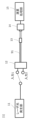
- FIG. 1 shows an example of a measuring device according to the present embodiment.
- An example of emitted light from the core C1 of the optical fiber to be measured is shown.
- An example of emitted light from the core C2 of the optical fiber to be measured is shown.
- a measurement example of the electric field strength distribution of emitted light is shown.
- An example of observed interference fringes is shown.
- 2 shows an example of a two-dimensional spatial frequency spectrum; An example of the measurement method of this embodiment is shown.
- the measuring apparatus of this embodiment includes a laser light generator 11 , an input core selector 12 , a collimator 13 , an electric field intensity distribution measuring unit 14 and an arithmetic processing unit 15 .
- the measurement apparatus of this embodiment uses these configurations to perform a method of measuring crosstalk between cores of the optical fiber 91 having multiple cores.
- the laser light generator 11 and the input core selector 12 function as means for making laser light incident on one core of the optical fiber 91 to be measured.
- the collimating section 13 functions as means for collimating the emitted light from each core provided in the optical fiber 91 to be measured with a difference in angle.
- the electric field strength distribution measuring unit 14 functions as electric field strength distribution measuring means capable of measuring the strength distribution of the interference waveform of the parallel light.
- the arithmetic processing unit 15 functions as interference waveform analysis means and crosstalk analysis means.
- the interference waveform analysis means uses the intensity distribution of the measured interference waveform to determine the interference component between the one core and any core different from the one core provided in the optical fiber 91 under test, and the interference DC components other than the component are obtained independently.
- Crosstalk analysis means acquires crosstalk from the one core to any core different from the one core using the interference component and the DC component.
- the arithmetic processing unit 15 can also be realized by a computer and a program, and the program can be recorded on a recording medium or provided through a network.
- the program of the present disclosure is a program for realizing a computer as each functional unit provided in the apparatus according to the present disclosure, and is a program for causing the computer to execute each step included in the method executed by the apparatus according to the present disclosure. .
- a coherent laser beam generated by the laser beam generator 11 is incident on an arbitrary core of the optical fiber 91 to be measured.
- the measuring apparatus of the present embodiment includes the input core selector 12, the light can be incident on a desired core of the optical fiber 19 to be measured.
- the emitted light from the optical fiber 91 to be measured is emitted to space after passing through the collimating section 13 such as a collimating lens.
- the collimating section 13 is an arbitrary lens that can convert emitted light into parallel light, and a general-purpose lens that collimates general-purpose SMF emitted light having one core at the center can be used.
- a general-purpose lens that collimates general-purpose SMF emitted light having one core at the center can be used.
- FIGS. 2A and 2B show an example of light emitted from each core of the optical fiber 91 to be measured.
- the output from the cores C1 and C2 passing through the collimator section 13 is The incident light beams L1 and L2 have an angular difference corresponding to the amount of deviation d from the central axis AF to the cores C1 and C2 and the focal length f of the collimating section 13 .
- FIGS. 1 and L2 have an angular difference corresponding to the amount of deviation d from the central axis AF to the cores C1 and C2 and the focal length f of the collimating section 13 .
- the emitted light beams L1 and L2 from the collimator unit 13 are measured by the electric field intensity distribution measuring unit 14 such as an image sensor.
- FIG. 3 shows the measurement of the electric field intensity distribution of emitted light.
- the light beams L1 and L2 emitted from the cores C1 and C2 are overlapped with an angle difference, and the intensity distribution is measured on the light receiving surface of the electric field intensity distribution measuring unit 14.
- the electric field intensity distribution measuring unit 14 can measure the intensity waveforms of the interference fringes of the emitted light beams L1 and L2.
- FIG. 2 shows an example in which the deviation amounts d from the central axis AF to the cores C1 and C2 are equal, but the present disclosure is not limited to this.
- the optical axis of the collimator 13 coincides with the central axis AF of the fiber 91 to be measured, and the light receiving surface of the electric field intensity distribution measuring section 14 is arranged on the central axis AF of the fiber 91 to be measured. Examples are shown, but the present disclosure is not limited thereto.
- the optical fiber 91 to be measured is a four-core fiber having cores C1, C2, C3, and C4, and the input core selector 12 causes laser light to enter only the core C1.
- the XT component from the core C1 is emitted from the cores C2, C3, and C4, and the interference fringes of these emitted lights L1, L2, L3, and L4 are measured.
- FIG. 4 shows an example of interference fringes observed by the electric field intensity distribution measurement unit 14.
- FIG. 4 shows that the emitted lights L1, L2, L3, and L4 from the cores C1, C2, C3, and C4 all exist in the same black solid line shape in the observation area in the electric field intensity distribution measurement unit 14, and they overlap. It shows how it is measured in the
- the interference fringes S1, S2 and S3 corresponding to the angular difference of each emitted light L1, L2, L3 and L4 can be measured.
- the intensity waveform I of the measured interference fringes S1, S2, and S3 can be expressed by the following equation.
- E 1 , E 2 , E 3 and E 4 are the electric field complex amplitudes of the emitted light from the cores C1, C2, C3 and C4.
- a 1 , A 2 , A 3 , A 4 and ⁇ 1 , ⁇ 2 , ⁇ 3 , ⁇ 4 are the amplitude and initial phase of E 1 , E 2 , E 3 , E 4 respectively. Since E 2 , E 3 , and E 4 are XT components, their DC components and interference components can be ignored, and only the DC component of E 1 and interference components with E 1 are observed.
- a two-dimensional spatial frequency spectrum as shown in FIG. 5 can be obtained.
- IDC which is the component of the first term in equation (2)
- the second and third terms are located at positions shifted from the origin depending on the angle difference in equation (1)
- I ⁇ 1- ⁇ 2 , I ⁇ 1- ⁇ 3 , and I ⁇ 1- ⁇ 4 which are the components of the fourth term, respectively.
- I DC , I ⁇ 1- ⁇ 2 , I ⁇ 1- ⁇ 3 , and I ⁇ 1- ⁇ 4 components obtained from this spatial frequency spectrum are extracted by bandpass filters.
- I DC , I ⁇ 1- ⁇ 2 , I ⁇ 1- ⁇ 3 , and I ⁇ 1- ⁇ 4 can be expressed by the following formula using
- P 1 , P 2 , P 3 and P 4 are the optical powers of the emitted light from core C1, core C2, core C3 and core C4, respectively.
- the inter-core XT from the core C1 can be obtained from the measured intensity waveform of the interference fringes.
- the present disclosure measures inter-core XT of MCF by executing the measurement procedure shown in FIG. 6 using the configuration of FIG. S101.
- a coherent laser beam is made incident on a desired core of the MCF to be measured.
- S102. Light emitted from all cores of the MCF is collimated and the electric field intensity distribution is measured.
- S103. By performing a Fourier transform on the measured electric field strength distribution, a DC component and a high frequency component with a spatial frequency corresponding to the angle difference of the emitted light from each core are extracted.
- S104 The extracted components are used to obtain XT from the desired core.
- the optical axes of the light emitted from all the cores provided in the multi-core optical fiber to be measured have different angles with respect to the light receiving surface of the electric field intensity distribution measuring unit 14. Then, using the interference intensity waveform of the light emitted from the multi-core optical fiber, it is possible to obtain the crosstalk from the core into which the light is incident to each of the other cores. Therefore, the present disclosure can easily measure inter-core crosstalk without fiber connection.
- examples of a 2-core optical fiber and a 4-core optical fiber in which no core is arranged on the central axis of the optical fiber 91 to be measured are shown, but the present disclosure is not limited to this.
- the optical fiber 91 to be measured of the present disclosure may have a core arranged on the central axis.
- the collimator 13 converts the light emitted from the core arranged at the center of the optical fiber 91 under measurement into parallel light parallel to the central axis of the optical fiber 91 under measurement.
- the optical axes of the light beams emitted from all the cores of the optical fiber 91 to be measured can be made to have different angles.
- This disclosure can be applied to the information and communications industry.
Landscapes
- Physics & Mathematics (AREA)
- General Physics & Mathematics (AREA)
- Chemical & Material Sciences (AREA)
- Analytical Chemistry (AREA)
- Optics & Photonics (AREA)
- Testing Of Optical Devices Or Fibers (AREA)
Priority Applications (3)
| Application Number | Priority Date | Filing Date | Title |
|---|---|---|---|
| JP2023552651A JP7632673B2 (ja) | 2021-10-08 | 2021-10-08 | コア間クロストークを測定する装置及び方法 |
| US18/692,981 US20240377281A1 (en) | 2021-10-08 | 2021-10-08 | Equipment and method for measuring crosstalk between cores of an optical fiber having multiple cores |
| PCT/JP2021/037323 WO2023058219A1 (ja) | 2021-10-08 | 2021-10-08 | コア間クロストークを測定する装置及び方法 |
Applications Claiming Priority (1)
| Application Number | Priority Date | Filing Date | Title |
|---|---|---|---|
| PCT/JP2021/037323 WO2023058219A1 (ja) | 2021-10-08 | 2021-10-08 | コア間クロストークを測定する装置及び方法 |
Publications (1)
| Publication Number | Publication Date |
|---|---|
| WO2023058219A1 true WO2023058219A1 (ja) | 2023-04-13 |
Family
ID=85804058
Family Applications (1)
| Application Number | Title | Priority Date | Filing Date |
|---|---|---|---|
| PCT/JP2021/037323 Ceased WO2023058219A1 (ja) | 2021-10-08 | 2021-10-08 | コア間クロストークを測定する装置及び方法 |
Country Status (3)
| Country | Link |
|---|---|
| US (1) | US20240377281A1 (https=) |
| JP (1) | JP7632673B2 (https=) |
| WO (1) | WO2023058219A1 (https=) |
Citations (4)
| Publication number | Priority date | Publication date | Assignee | Title |
|---|---|---|---|---|
| JPS56168506A (en) * | 1980-04-25 | 1981-12-24 | Siemens Ag | Detector with optical fiber |
| JP2013505441A (ja) * | 2009-09-18 | 2013-02-14 | ルナ イノベーションズ インコーポレイテッド | 光学的位置および/または形状センシング |
| JP2017156335A (ja) * | 2016-02-26 | 2017-09-07 | 株式会社フジクラ | マルチコアファイバのクロストーク測定方法及び測定装置 |
| US20210080644A1 (en) * | 2017-07-13 | 2021-03-18 | Nanyang Technological University | Fiber preform, optical fiber, methods for forming the same, and optical devices having the optical fiber |
-
2021
- 2021-10-08 US US18/692,981 patent/US20240377281A1/en active Pending
- 2021-10-08 JP JP2023552651A patent/JP7632673B2/ja active Active
- 2021-10-08 WO PCT/JP2021/037323 patent/WO2023058219A1/ja not_active Ceased
Patent Citations (4)
| Publication number | Priority date | Publication date | Assignee | Title |
|---|---|---|---|---|
| JPS56168506A (en) * | 1980-04-25 | 1981-12-24 | Siemens Ag | Detector with optical fiber |
| JP2013505441A (ja) * | 2009-09-18 | 2013-02-14 | ルナ イノベーションズ インコーポレイテッド | 光学的位置および/または形状センシング |
| JP2017156335A (ja) * | 2016-02-26 | 2017-09-07 | 株式会社フジクラ | マルチコアファイバのクロストーク測定方法及び測定装置 |
| US20210080644A1 (en) * | 2017-07-13 | 2021-03-18 | Nanyang Technological University | Fiber preform, optical fiber, methods for forming the same, and optical devices having the optical fiber |
Also Published As
| Publication number | Publication date |
|---|---|
| JPWO2023058219A1 (https=) | 2023-04-13 |
| US20240377281A1 (en) | 2024-11-14 |
| JP7632673B2 (ja) | 2025-02-19 |
Similar Documents
| Publication | Publication Date | Title |
|---|---|---|
| CN110186577B (zh) | 超快光场的信息实时测量系统 | |
| JP6862712B2 (ja) | 光ファイバ評価方法及び光ファイバ評価装置 | |
| US10041857B2 (en) | Method of evaluating characteristics of optical fiber, and apparatus of evaluating characteristics of optical fiber | |
| JP7322960B2 (ja) | 光ファイバ試験方法および光ファイバ試験装置 | |
| CN106950811B (zh) | 一种复合数字全息成像方法及装置 | |
| US20140347659A1 (en) | Stationary Waveguide Spectrum Analyser | |
| GB2565889A (en) | Optical-fiber output beam profile measurement method and optical-fiber output beam profile measurement apparatus | |
| WO2020075343A1 (ja) | 光ファイバ試験方法及び光ファイバ試験装置 | |
| CN116107097B (zh) | 一种基于光纤输出光强分布中提取角向特征参量的少模光纤模式分解方法 | |
| Iuzzolino et al. | Preliminary results on the characterization and performances of ZBLAN fiber for infrared spectrographs | |
| CN110160624B (zh) | 一种用于三维振动测量的光纤点衍射装置及测量方法 | |
| WO2023058219A1 (ja) | コア間クロストークを測定する装置及び方法 | |
| Osintseva et al. | Identification of the Hermite-Gaussian and Bessel modes of a terahertz beam with diffractive optical elements | |
| CN212300381U (zh) | 基于频移干涉光纤环衰荡的光纤光栅传感解调装置 | |
| CN104897376B (zh) | 一种激光器线宽测量方法及系统 | |
| Xu et al. | Quantitative diagnosis of the out-of-plane displacement derivative with temporal-phase-shift shearography | |
| CN113465878A (zh) | 一种保偏少模光纤拍长测量装置和测量方法 | |
| CN208805343U (zh) | 光缆跳线头内部光纤断点的光谱测量装置 | |
| CN112665823A (zh) | 一种光纤模式时域能量波动曲线测量装置和测量方法 | |
| Wang et al. | Rapid one-shot dual-shearing digital shearography using a spatial light modulator | |
| CN106840008A (zh) | 一种光纤间距测量系统及测量方法 | |
| JP7586329B2 (ja) | コア間の電力結合係数を算出する装置、方法及びシステム | |
| JP2016099290A (ja) | 光学部材及び光ファイバの評価装置 | |
| Zhou et al. | Analysis of phase calculation error introduced by the extinction ratio in instantaneous phase shifting interference | |
| US20230092539A1 (en) | Spectroferometer |
Legal Events
| Date | Code | Title | Description |
|---|---|---|---|
| 121 | Ep: the epo has been informed by wipo that ep was designated in this application |
Ref document number: 21959961 Country of ref document: EP Kind code of ref document: A1 |
|
| WWE | Wipo information: entry into national phase |
Ref document number: 18692981 Country of ref document: US |
|
| WWE | Wipo information: entry into national phase |
Ref document number: 2023552651 Country of ref document: JP |
|
| NENP | Non-entry into the national phase |
Ref country code: DE |
|
| 122 | Ep: pct application non-entry in european phase |
Ref document number: 21959961 Country of ref document: EP Kind code of ref document: A1 |