WO2023058219A1 - Device and method for measuring inter-core crosstalk - Google Patents
Device and method for measuring inter-core crosstalk Download PDFInfo
- Publication number
- WO2023058219A1 WO2023058219A1 PCT/JP2021/037323 JP2021037323W WO2023058219A1 WO 2023058219 A1 WO2023058219 A1 WO 2023058219A1 JP 2021037323 W JP2021037323 W JP 2021037323W WO 2023058219 A1 WO2023058219 A1 WO 2023058219A1
- Authority
- WO
- WIPO (PCT)
- Prior art keywords
- core
- component
- optical fiber
- crosstalk
- interference
- Prior art date
Links
- 238000000034 method Methods 0.000 title claims abstract description 20
- 239000013307 optical fiber Substances 0.000 claims abstract description 46
- 230000005684 electric field Effects 0.000 claims description 19
- 238000001228 spectrum Methods 0.000 claims description 9
- 238000000691 measurement method Methods 0.000 claims description 2
- 239000000835 fiber Substances 0.000 abstract description 15
- 238000005259 measurement Methods 0.000 description 12
- 230000003287 optical effect Effects 0.000 description 6
- 230000005540 biological transmission Effects 0.000 description 5
- 238000012545 processing Methods 0.000 description 4
- 230000001427 coherent effect Effects 0.000 description 3
- 238000004891 communication Methods 0.000 description 2
- 230000035945 sensitivity Effects 0.000 description 2
- 238000012360 testing method Methods 0.000 description 2
- 239000000470 constituent Substances 0.000 description 1
- 230000004927 fusion Effects 0.000 description 1
- 230000000873 masking effect Effects 0.000 description 1
Images


Classifications
-
- G—PHYSICS
- G01—MEASURING; TESTING
- G01M—TESTING STATIC OR DYNAMIC BALANCE OF MACHINES OR STRUCTURES; TESTING OF STRUCTURES OR APPARATUS, NOT OTHERWISE PROVIDED FOR
- G01M11/00—Testing of optical apparatus; Testing structures by optical methods not otherwise provided for
- G01M11/02—Testing optical properties
-
- G—PHYSICS
- G02—OPTICS
- G02B—OPTICAL ELEMENTS, SYSTEMS OR APPARATUS
- G02B6/00—Light guides; Structural details of arrangements comprising light guides and other optical elements, e.g. couplings
Definitions
- It relates to a measuring device and a measuring method that can acquire inter-core crosstalk of an optical fiber having multiple cores.
- MCF multi-core fiber
- SMF single-mode fiber
- a power meter method in which each core of the MCF and the SMF are directly fusion spliced, is generally used to measure the intensity of light emitted from each core.
- the power meter method has the advantage of a simple configuration, but requires alignment and connection for the number of cores, and takes time for measurement. Therefore, a technique that can eliminate the need for connection between each core of the MCF and the SMF is desirable.
- Non-Patent Document 1 a method of measuring the emitted light from the MCF with an image sensor and obtaining XT from its intensity has been proposed (Non-Patent Document 1).
- the MCF emitted light is imaged by a magnifying optical system and measured by an image sensor, thereby independently measuring the electric field strength distribution in each core. This makes it possible to measure XT without connecting to a fiber or the like.
- each pixel in the sensor may have different sensitivities, and even if the light intensity emitted from each core is the same, the light intensity acquired by the image sensor may differ. Therefore, it is necessary to compensate for the difference in sensitivity of each pixel.
- Non-Patent Document 1 since the minimum measurable XT depends on the dynamic range of the image sensor, in Non-Patent Document 1, after measuring the signal light intensity from the reference core, the end face of the reference core is physically masked with a light shielding tape, Light emitted from other cores is measured. Therefore, even in Non-Patent Document 1, there is a problem that measurement of XT is not easy.
- An object of the present disclosure is to provide a method for easily measuring the XT of a fiber having multiple cores.
- interference light of each core emitted from a fiber having multiple cores is measured.
- Inter-core XT can be obtained by analyzing this interference light.
- the inter-core crosstalk measurement device of the present disclosure includes: means for injecting a laser beam into one core of an optical fiber having multiple cores; means for collimating the emitted light from each core provided in the optical fiber with an angular difference; electric field strength distribution measuring means capable of measuring the strength distribution of the interference waveform of the parallel light; Using the measured intensity distribution of the interference waveform, an interference component between the one core and any core different from the one core provided in the optical fiber and a DC component other than the interference component are independently determined. an obtainable interference waveform analysis means; Crosstalk analysis means capable of acquiring crosstalk from the one core to any core different from the one core using the interference component and the DC component; characterized by having
- the method for measuring inter-core crosstalk of the present disclosure includes: A method for measuring crosstalk between cores of an optical fiber having multiple cores, comprising: injecting light into one core of the optical fiber; converting light emitted from each core provided in the optical fiber into parallel light with an angular difference; measuring the intensity distribution of the interference waveform of the parallel light; Using the interference waveform of the parallel light, an interference component between the one core and any core different from the one core provided in the optical fiber and a DC component other than the interference component are obtained independently. matter, Obtaining crosstalk from the one core to any core different from the one core using the interference component and the DC component; characterized by
- the XT of a fiber having multiple cores can be obtained without splicing optical fibers and without masking the reference core end face. Therefore, the present disclosure can easily measure the XT of a fiber having multiple cores.
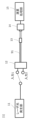
- FIG. 1 shows an example of a measuring device according to the present embodiment.
- An example of emitted light from the core C1 of the optical fiber to be measured is shown.
- An example of emitted light from the core C2 of the optical fiber to be measured is shown.
- a measurement example of the electric field strength distribution of emitted light is shown.
- An example of observed interference fringes is shown.
- 2 shows an example of a two-dimensional spatial frequency spectrum; An example of the measurement method of this embodiment is shown.
- the measuring apparatus of this embodiment includes a laser light generator 11 , an input core selector 12 , a collimator 13 , an electric field intensity distribution measuring unit 14 and an arithmetic processing unit 15 .
- the measurement apparatus of this embodiment uses these configurations to perform a method of measuring crosstalk between cores of the optical fiber 91 having multiple cores.
- the laser light generator 11 and the input core selector 12 function as means for making laser light incident on one core of the optical fiber 91 to be measured.
- the collimating section 13 functions as means for collimating the emitted light from each core provided in the optical fiber 91 to be measured with a difference in angle.
- the electric field strength distribution measuring unit 14 functions as electric field strength distribution measuring means capable of measuring the strength distribution of the interference waveform of the parallel light.
- the arithmetic processing unit 15 functions as interference waveform analysis means and crosstalk analysis means.
- the interference waveform analysis means uses the intensity distribution of the measured interference waveform to determine the interference component between the one core and any core different from the one core provided in the optical fiber 91 under test, and the interference DC components other than the component are obtained independently.
- Crosstalk analysis means acquires crosstalk from the one core to any core different from the one core using the interference component and the DC component.
- the arithmetic processing unit 15 can also be realized by a computer and a program, and the program can be recorded on a recording medium or provided through a network.
- the program of the present disclosure is a program for realizing a computer as each functional unit provided in the apparatus according to the present disclosure, and is a program for causing the computer to execute each step included in the method executed by the apparatus according to the present disclosure. .
- a coherent laser beam generated by the laser beam generator 11 is incident on an arbitrary core of the optical fiber 91 to be measured.
- the measuring apparatus of the present embodiment includes the input core selector 12, the light can be incident on a desired core of the optical fiber 19 to be measured.
- the emitted light from the optical fiber 91 to be measured is emitted to space after passing through the collimating section 13 such as a collimating lens.
- the collimating section 13 is an arbitrary lens that can convert emitted light into parallel light, and a general-purpose lens that collimates general-purpose SMF emitted light having one core at the center can be used.
- a general-purpose lens that collimates general-purpose SMF emitted light having one core at the center can be used.
- FIGS. 2A and 2B show an example of light emitted from each core of the optical fiber 91 to be measured.
- the output from the cores C1 and C2 passing through the collimator section 13 is The incident light beams L1 and L2 have an angular difference corresponding to the amount of deviation d from the central axis AF to the cores C1 and C2 and the focal length f of the collimating section 13 .
- FIGS. 1 and L2 have an angular difference corresponding to the amount of deviation d from the central axis AF to the cores C1 and C2 and the focal length f of the collimating section 13 .
- the emitted light beams L1 and L2 from the collimator unit 13 are measured by the electric field intensity distribution measuring unit 14 such as an image sensor.
- FIG. 3 shows the measurement of the electric field intensity distribution of emitted light.
- the light beams L1 and L2 emitted from the cores C1 and C2 are overlapped with an angle difference, and the intensity distribution is measured on the light receiving surface of the electric field intensity distribution measuring unit 14.
- the electric field intensity distribution measuring unit 14 can measure the intensity waveforms of the interference fringes of the emitted light beams L1 and L2.
- FIG. 2 shows an example in which the deviation amounts d from the central axis AF to the cores C1 and C2 are equal, but the present disclosure is not limited to this.
- the optical axis of the collimator 13 coincides with the central axis AF of the fiber 91 to be measured, and the light receiving surface of the electric field intensity distribution measuring section 14 is arranged on the central axis AF of the fiber 91 to be measured. Examples are shown, but the present disclosure is not limited thereto.
- the optical fiber 91 to be measured is a four-core fiber having cores C1, C2, C3, and C4, and the input core selector 12 causes laser light to enter only the core C1.
- the XT component from the core C1 is emitted from the cores C2, C3, and C4, and the interference fringes of these emitted lights L1, L2, L3, and L4 are measured.
- FIG. 4 shows an example of interference fringes observed by the electric field intensity distribution measurement unit 14.
- FIG. 4 shows that the emitted lights L1, L2, L3, and L4 from the cores C1, C2, C3, and C4 all exist in the same black solid line shape in the observation area in the electric field intensity distribution measurement unit 14, and they overlap. It shows how it is measured in the
- the interference fringes S1, S2 and S3 corresponding to the angular difference of each emitted light L1, L2, L3 and L4 can be measured.
- the intensity waveform I of the measured interference fringes S1, S2, and S3 can be expressed by the following equation.
- E 1 , E 2 , E 3 and E 4 are the electric field complex amplitudes of the emitted light from the cores C1, C2, C3 and C4.
- a 1 , A 2 , A 3 , A 4 and ⁇ 1 , ⁇ 2 , ⁇ 3 , ⁇ 4 are the amplitude and initial phase of E 1 , E 2 , E 3 , E 4 respectively. Since E 2 , E 3 , and E 4 are XT components, their DC components and interference components can be ignored, and only the DC component of E 1 and interference components with E 1 are observed.
- a two-dimensional spatial frequency spectrum as shown in FIG. 5 can be obtained.
- IDC which is the component of the first term in equation (2)
- the second and third terms are located at positions shifted from the origin depending on the angle difference in equation (1)
- I ⁇ 1- ⁇ 2 , I ⁇ 1- ⁇ 3 , and I ⁇ 1- ⁇ 4 which are the components of the fourth term, respectively.
- I DC , I ⁇ 1- ⁇ 2 , I ⁇ 1- ⁇ 3 , and I ⁇ 1- ⁇ 4 components obtained from this spatial frequency spectrum are extracted by bandpass filters.
- I DC , I ⁇ 1- ⁇ 2 , I ⁇ 1- ⁇ 3 , and I ⁇ 1- ⁇ 4 can be expressed by the following formula using
- P 1 , P 2 , P 3 and P 4 are the optical powers of the emitted light from core C1, core C2, core C3 and core C4, respectively.
- the inter-core XT from the core C1 can be obtained from the measured intensity waveform of the interference fringes.
- the present disclosure measures inter-core XT of MCF by executing the measurement procedure shown in FIG. 6 using the configuration of FIG. S101.
- a coherent laser beam is made incident on a desired core of the MCF to be measured.
- S102. Light emitted from all cores of the MCF is collimated and the electric field intensity distribution is measured.
- S103. By performing a Fourier transform on the measured electric field strength distribution, a DC component and a high frequency component with a spatial frequency corresponding to the angle difference of the emitted light from each core are extracted.
- S104 The extracted components are used to obtain XT from the desired core.
- the optical axes of the light emitted from all the cores provided in the multi-core optical fiber to be measured have different angles with respect to the light receiving surface of the electric field intensity distribution measuring unit 14. Then, using the interference intensity waveform of the light emitted from the multi-core optical fiber, it is possible to obtain the crosstalk from the core into which the light is incident to each of the other cores. Therefore, the present disclosure can easily measure inter-core crosstalk without fiber connection.
- examples of a 2-core optical fiber and a 4-core optical fiber in which no core is arranged on the central axis of the optical fiber 91 to be measured are shown, but the present disclosure is not limited to this.
- the optical fiber 91 to be measured of the present disclosure may have a core arranged on the central axis.
- the collimator 13 converts the light emitted from the core arranged at the center of the optical fiber 91 under measurement into parallel light parallel to the central axis of the optical fiber 91 under measurement.
- the optical axes of the light beams emitted from all the cores of the optical fiber 91 to be measured can be made to have different angles.
- This disclosure can be applied to the information and communications industry.
Abstract
The purpose of the present disclosure is to make it possible to easily measure inter-core crosstalk without connecting a fiber. The present disclosure is a method for measuring inter-core crosstalk for an optical fiber that has a plurality of cores. The method is characterized by inputting light into one core of the optical fiber, collimating the output light from each of the cores of the optical fiber to produce parallel light that has respective angular differences, measuring an intensity distribution for an interference waveform for the parallel light, using the interference waveform for the parallel light to independently acquire each of an interference component between the one core and a core of the optical fiber that is different from the one core and a direct-current component that is not the interference component, and using the interference component and the direct-current component to acquire the crosstalk from the one core to the core that is different from the one core.
Description
複数コアを有する光ファイバのコア間クロストークを取得できる測定装置及びその測定方法に関する。
It relates to a measuring device and a measuring method that can acquire inter-core crosstalk of an optical fiber having multiple cores.
近年、伝送トラフィックの急激な増加に伴い、現在の伝送路で用いられているシングルモードファイバ(SMF)に代わって複数のコアを有するマルチコアファイバ(MCF)が更なる大容量化を可能にするものとして大きな注目を集めている。MCFを用いた伝送では、従来のSMFに対してコア数分だけ伝送容量の拡大が可能である。一方で、MCFでは、コア間クロストーク(XT)が伝送容量を制限するため、XTを可能な限り抑圧する必要がある。また、MCFのXTが所望の値を満たすか評価するために、発生するXTの測定が必要となる。
In recent years, with the rapid increase in transmission traffic, multi-core fiber (MCF), which has multiple cores, has enabled further increase in capacity in place of single-mode fiber (SMF) used in current transmission lines. attracting a great deal of attention as In transmission using MCF, it is possible to expand transmission capacity by the number of cores compared to conventional SMF. On the other hand, in MCF, inter-core crosstalk (XT) limits the transmission capacity, so it is necessary to suppress XT as much as possible. Also, a measurement of the generated XT is required to assess whether the MCF XT satisfies the desired value.
MCFのXTを測定するためには、各コアから出射される光強度を測定し、コア間での光強度比を取得する必要がある。各コアからの出射光強度の測定には、MCFの各コアとSMFを直接融着接続するパワーメータ法が一般的に用いられる。パワーメータ法は構成がシンプルである利点を有するが、コア数分だけ調心を行い接続する必要があり、測定に時間を要する。したがって、MCFの各コアとSMFを接続不要にできる手法が望ましい。
In order to measure the XT of the MCF, it is necessary to measure the light intensity emitted from each core and obtain the light intensity ratio between the cores. A power meter method, in which each core of the MCF and the SMF are directly fusion spliced, is generally used to measure the intensity of light emitted from each core. The power meter method has the advantage of a simple configuration, but requires alignment and connection for the number of cores, and takes time for measurement. Therefore, a technique that can eliminate the need for connection between each core of the MCF and the SMF is desirable.
MCFの各コアとSMFを接続不要にするための手法として、MCFからの出射光をイメージセンサで測定し、その強度からXTを取得する手法が提案されている(非特許文献1)。この手法では、MCF出射光を拡大光学系で結像し、これをイメージセンサで測定することで、各コアにおける電界強度分布をそれぞれ独立に測定する。これにより、ファイバ等と接続せずにXTの測定が可能である。
As a method for eliminating the need to connect each core of the MCF and the SMF, a method of measuring the emitted light from the MCF with an image sensor and obtaining XT from its intensity has been proposed (Non-Patent Document 1). In this technique, the MCF emitted light is imaged by a magnifying optical system and measured by an image sensor, thereby independently measuring the electric field strength distribution in each core. This makes it possible to measure XT without connecting to a fiber or the like.
一方で、イメージセンサではセンサ内の各ピクセルで感度が異なる場合があり、各コアからの出射光強度が同じ場合でも、イメージセンサが取得する光強度が異なる場合がある。したがって、各ピクセルの感度の違いを補正する必要がある。
On the other hand, in an image sensor, each pixel in the sensor may have different sensitivities, and even if the light intensity emitted from each core is the same, the light intensity acquired by the image sensor may differ. Therefore, it is necessary to compensate for the difference in sensitivity of each pixel.
また測定可能な最低XTは、イメージセンサのダイナミックレンジに依存するため、非特許文献1では基準となるコアからの信号光強度の測定後に、基準コア端面を遮光テープで物理的にマスキングをし、それ以外のコアからの出射光を測定する。したがって、非特許文献1においてもXTの測定が容易ではないという問題がある。
In addition, since the minimum measurable XT depends on the dynamic range of the image sensor, in Non-Patent Document 1, after measuring the signal light intensity from the reference core, the end face of the reference core is physically masked with a light shielding tape, Light emitted from other cores is measured. Therefore, even in Non-Patent Document 1, there is a problem that measurement of XT is not easy.
本開示の目的は、複数コアを有するファイバのXTを簡易に測定できる手法を提供することにある。
An object of the present disclosure is to provide a method for easily measuring the XT of a fiber having multiple cores.
本開示では、複数コアを有するファイバから出射した各コアの干渉光を測定する。この干渉光を解析することでコア間のXTを取得可能にする。
In the present disclosure, interference light of each core emitted from a fiber having multiple cores is measured. Inter-core XT can be obtained by analyzing this interference light.
具体的には、本開示のコア間クロストーク測定装置は、
複数コアを有する光ファイバの一つのコアにレーザ光を入射する手段と、
前記光ファイバに備わる各コアからの出射光がそれぞれ角度差を有した状態で平行光する手段と、
前記平行光の干渉波形の強度分布を測定できる電界強度分布測定手段と、
測定した前記干渉波形の強度分布を用いて、前記一つのコアと前記光ファイバに備わる前記一つのコアと異なるいずれかのコアとの間の干渉成分及び前記干渉成分以外の直流成分をそれぞれ独立に取得できる干渉波形解析手段と、
前記干渉成分及び前記直流成分を用いて、前記一つのコアから前記一つのコアと異なるいずれかのコアへのクロストークを取得できるクロストーク解析手段と、
を有することを特徴とする。 Specifically, the inter-core crosstalk measurement device of the present disclosure includes:
means for injecting a laser beam into one core of an optical fiber having multiple cores;
means for collimating the emitted light from each core provided in the optical fiber with an angular difference;
electric field strength distribution measuring means capable of measuring the strength distribution of the interference waveform of the parallel light;
Using the measured intensity distribution of the interference waveform, an interference component between the one core and any core different from the one core provided in the optical fiber and a DC component other than the interference component are independently determined. an obtainable interference waveform analysis means;
Crosstalk analysis means capable of acquiring crosstalk from the one core to any core different from the one core using the interference component and the DC component;
characterized by having
具体的には、本開示のコア間クロストークの測定方法は、
複数コアを有する光ファイバのコア間クロストークの測定方法であって、
前記光ファイバの一つのコアに光を入射すること、
前記光ファイバに備わる各コアからの出射光が角度差を有する状態で平行光にすること、
前記平行光の干渉波形の強度分布を測定すること、
前記平行光の干渉波形を用いて、前記一つのコアと前記光ファイバに備わる前記一つのコアと異なるいずれかのコアとの間の干渉成分及び前記干渉成分以外の直流成分をそれぞれ独立に取得すること、
前記干渉成分及び直流成分を用いて、前記一つのコアから前記一つのコアと異なるいずれかのコアへのクロストークを取得すること、
を特徴とする。 Specifically, the method for measuring inter-core crosstalk of the present disclosure includes:
A method for measuring crosstalk between cores of an optical fiber having multiple cores, comprising:
injecting light into one core of the optical fiber;
converting light emitted from each core provided in the optical fiber into parallel light with an angular difference;
measuring the intensity distribution of the interference waveform of the parallel light;
Using the interference waveform of the parallel light, an interference component between the one core and any core different from the one core provided in the optical fiber and a DC component other than the interference component are obtained independently. matter,
Obtaining crosstalk from the one core to any core different from the one core using the interference component and the DC component;
characterized by
本開示では、光ファイバを接続することなく、かつ基準コア端面のマスキングを行うことなく、複数コアを有するファイバのXTを取得することができる。このため、本開示は、複数コアを有するファイバのXTを簡易に測定することができる。
In the present disclosure, the XT of a fiber having multiple cores can be obtained without splicing optical fibers and without masking the reference core end face. Therefore, the present disclosure can easily measure the XT of a fiber having multiple cores.
以下、本開示の実施形態について、図面を参照しながら詳細に説明する。なお、本開示は、以下に示す実施形態に限定されるものではない。これらの実施の例は例示に過ぎず、本開示は当業者の知識に基づいて種々の変更、改良を施した形態で実施することができる。なお、本明細書及び図面において符号が同じ構成要素は、相互に同一のものを示すものとする。
Hereinafter, embodiments of the present disclosure will be described in detail with reference to the drawings. Note that the present disclosure is not limited to the embodiments shown below. These implementation examples are merely illustrative, and the present disclosure can be implemented in various modified and improved forms based on the knowledge of those skilled in the art. In addition, in this specification and the drawings, constituent elements having the same reference numerals are the same as each other.
図1に本開示を実施するための一例を示す。本実施形態の測定装置は、レーザ光発生部11、入力コア選択部12、コリメート部13、電界強度分布測定部14、演算処理部15、を備える。本実施形態の測定装置は、これらの構成を用いて、複数コアを有する被測定光ファイバ91のコア間クロストークの測定方法を実行する。
An example for implementing the present disclosure is shown in FIG. The measuring apparatus of this embodiment includes a laser light generator 11 , an input core selector 12 , a collimator 13 , an electric field intensity distribution measuring unit 14 and an arithmetic processing unit 15 . The measurement apparatus of this embodiment uses these configurations to perform a method of measuring crosstalk between cores of the optical fiber 91 having multiple cores.
レーザ光発生部11及び入力コア選択部12は、被測定光ファイバ91の一つのコアにレーザ光を入射する手段として機能する。
コリメート部13は、被測定光ファイバ91に備わる各コアからの出射光がそれぞれ角度差を有した状態で平行光にする手段として機能する。
電界強度分布測定部14は、前記平行光の干渉波形の強度分布を測定できる電界強度分布測定手段として機能する。 Thelaser light generator 11 and the input core selector 12 function as means for making laser light incident on one core of the optical fiber 91 to be measured.
Thecollimating section 13 functions as means for collimating the emitted light from each core provided in the optical fiber 91 to be measured with a difference in angle.
The electric field strengthdistribution measuring unit 14 functions as electric field strength distribution measuring means capable of measuring the strength distribution of the interference waveform of the parallel light.
コリメート部13は、被測定光ファイバ91に備わる各コアからの出射光がそれぞれ角度差を有した状態で平行光にする手段として機能する。
電界強度分布測定部14は、前記平行光の干渉波形の強度分布を測定できる電界強度分布測定手段として機能する。 The
The
The electric field strength
演算処理部15は、干渉波形解析手段及びクロストーク解析手段として機能する。
干渉波形解析手段は、測定した前記干渉波形の強度分布を用いて、前記一つのコアと被測定光ファイバ91に備わる前記一つのコアと異なるいずれかのコアとの間の干渉成分、及び前記干渉成分以外の直流成分を、それぞれ独立に取得する。
クロストーク解析手段は、前記干渉成分及び前記直流成分を用いて、前記一つのコアから前記一つのコアと異なるいずれかのコアへのクロストークを取得する。 Thearithmetic processing unit 15 functions as interference waveform analysis means and crosstalk analysis means.
The interference waveform analysis means uses the intensity distribution of the measured interference waveform to determine the interference component between the one core and any core different from the one core provided in theoptical fiber 91 under test, and the interference DC components other than the component are obtained independently.
Crosstalk analysis means acquires crosstalk from the one core to any core different from the one core using the interference component and the DC component.
干渉波形解析手段は、測定した前記干渉波形の強度分布を用いて、前記一つのコアと被測定光ファイバ91に備わる前記一つのコアと異なるいずれかのコアとの間の干渉成分、及び前記干渉成分以外の直流成分を、それぞれ独立に取得する。
クロストーク解析手段は、前記干渉成分及び前記直流成分を用いて、前記一つのコアから前記一つのコアと異なるいずれかのコアへのクロストークを取得する。 The
The interference waveform analysis means uses the intensity distribution of the measured interference waveform to determine the interference component between the one core and any core different from the one core provided in the
Crosstalk analysis means acquires crosstalk from the one core to any core different from the one core using the interference component and the DC component.
演算処理部15は、コンピュータとプログラムによっても実現でき、プログラムを記録媒体に記録することも、ネットワークを通して提供することも可能である。本開示のプログラムは、本開示に係る装置に備わる各機能部としてコンピュータを実現させるためのプログラムであり、本開示に係る装置が実行する方法に備わる各ステップをコンピュータに実行させるためのプログラムである。
The arithmetic processing unit 15 can also be realized by a computer and a program, and the program can be recorded on a recording medium or provided through a network. The program of the present disclosure is a program for realizing a computer as each functional unit provided in the apparatus according to the present disclosure, and is a program for causing the computer to execute each step included in the method executed by the apparatus according to the present disclosure. .
レーザ光発生部11により発生したコヒーレントなレーザ光は、被測定光ファイバ91の任意のコアへ入射される。ここで、本実施形態の測定装置は、入力コア選択部12を備えるため、被測定光ファイバ19の所望のコアへ入射することができる。被測定光ファイバ91の出射光は、コリメートレンズ等のコリメート部13を通過後、空間へと出射される。
A coherent laser beam generated by the laser beam generator 11 is incident on an arbitrary core of the optical fiber 91 to be measured. Here, since the measuring apparatus of the present embodiment includes the input core selector 12, the light can be incident on a desired core of the optical fiber 19 to be measured. The emitted light from the optical fiber 91 to be measured is emitted to space after passing through the collimating section 13 such as a collimating lens.
ここで、コリメート部13は、出射光を平行光へと変換できる任意のレンズであり、中心にコアを一つ有する汎用SMF出射光をコリメートする汎用的なものを用いることができる。このコリメート部13を被測定光ファイバ91の出射端に配置することで、各コアからの出射光に角度差が生じる。
Here, the collimating section 13 is an arbitrary lens that can convert emitted light into parallel light, and a general-purpose lens that collimates general-purpose SMF emitted light having one core at the center can be used. By arranging the collimator 13 at the output end of the optical fiber 91 to be measured, an angle difference is generated in the output light from each core.
図2A及び図2Bに被測定光ファイバ91の各コアからの出射光の一例を示す。図2A及び図2Bに示すように、被測定ファイバ91の中心軸AFから距離dずれた位置にコアC1及びC2が配置されているため、コリメート部13を通過したコアC1及びC2からの出射光L1及びL2には、中心軸AFからコアC1及びC2までのずれ量dとコリメート部13の焦点距離fに応じた角度差が生じる。ここで、図2A及び図2Bにおいて、各コアC1及びC2の出射光L1及びL2がコリメート部13のレンズの中心を通過する成分について着目すると、コリメート部13からの出射光L1及びL2の角度差2θは、以下の関係となる。

2A and 2B show an example of light emitted from each core of the optical fiber 91 to be measured. As shown in FIGS. 2A and 2B, since the cores C1 and C2 are arranged at positions displaced by the distance d from the central axis AF of the fiber under test 91, the output from the cores C1 and C2 passing through the collimator section 13 is The incident light beams L1 and L2 have an angular difference corresponding to the amount of deviation d from the central axis AF to the cores C1 and C2 and the focal length f of the collimating section 13 . Here, in FIGS. 2A and 2B, focusing on the components of the emitted light L1 and L2 of each of the cores C1 and C2 that pass through the center of the lens of the collimator 13, the angular difference between the emitted light L1 and L2 from the collimator 13 is 2θ has the following relationship.
コリメート部13からの各出射光L1及びL2は、イメージセンサ等の電界強度分布測定部14で測定される。図3に出射光の電界強度分布測定について示す。図3では、各コアC1及びC2からの出射光L1及びL2が角度差を有した状態で重なり、この強度分布が電界強度分布測定部14の受光面で測定され様子を表している。ここで、各コアC1及びC2からの出射光L1及びL2はコヒーレントなレーザ光であることから、電界強度分布測定部14では出射光L1及びL2の干渉縞の強度波形が測定できる。
The emitted light beams L1 and L2 from the collimator unit 13 are measured by the electric field intensity distribution measuring unit 14 such as an image sensor. FIG. 3 shows the measurement of the electric field intensity distribution of emitted light. In FIG. 3, the light beams L1 and L2 emitted from the cores C1 and C2 are overlapped with an angle difference, and the intensity distribution is measured on the light receiving surface of the electric field intensity distribution measuring unit 14. FIG. Since the emitted light beams L1 and L2 from the cores C1 and C2 are coherent laser beams, the electric field intensity distribution measuring unit 14 can measure the intensity waveforms of the interference fringes of the emitted light beams L1 and L2.
なお、図2では、中心軸AFからコアC1及びC2までのずれ量dが等しい例を示すが、本開示はこれに限定されない。また図3では、コリメート部13の光軸が被測定ファイバ91の中心軸AFと一致しており、被測定ファイバ91の中心軸AF上に電界強度分布測定部14の受光面が配置されている例を示すが、本開示はこれに限定されない。
Note that FIG. 2 shows an example in which the deviation amounts d from the central axis AF to the cores C1 and C2 are equal, but the present disclosure is not limited to this. 3, the optical axis of the collimator 13 coincides with the central axis AF of the fiber 91 to be measured, and the light receiving surface of the electric field intensity distribution measuring section 14 is arranged on the central axis AF of the fiber 91 to be measured. Examples are shown, but the present disclosure is not limited thereto.
被測定光ファイバ91がコアC1、C2、C3、C4を有する4コアファイバであり、入力コア選択部12がコアC1にのみにレーザ光を入射する場合を考える。4コアファイバの出射端では、コアC1からの出射光に加えてコアC1からのXT成分がコアC2、C3、及びC4から出射され、これらの出射光L1、L2、L3及びL4の干渉縞が測定される。
Consider a case where the optical fiber 91 to be measured is a four-core fiber having cores C1, C2, C3, and C4, and the input core selector 12 causes laser light to enter only the core C1. At the output end of the 4-core fiber, in addition to the light emitted from the core C1, the XT component from the core C1 is emitted from the cores C2, C3, and C4, and the interference fringes of these emitted lights L1, L2, L3, and L4 are measured.
図4に、電界強度分布測定部14で観測される干渉縞の例を示す。図4は、電界強度分布測定部14における観測領域内に各コアC1、C2、C3、C4からの出射光L1、L2、L3及びL4が全て同じ黒の実線の形状で存在し、それらが重なった状態で測定される様子を示している。
FIG. 4 shows an example of interference fringes observed by the electric field intensity distribution measurement unit 14. FIG. 4 shows that the emitted lights L1, L2, L3, and L4 from the cores C1, C2, C3, and C4 all exist in the same black solid line shape in the observation area in the electric field intensity distribution measurement unit 14, and they overlap. It shows how it is measured in the
ここで、本開示では、出射光L1、L2、L3及びL4は重なっているため、各出射光L1、L2、L3及びL4の角度差に対応した干渉縞S1、S2、S3が測定できる。測定される干渉縞S1、S2、S3の強度波形Iは以下の式で表すことができる。

Here, in the present disclosure, since the emitted lights L1, L2, L3 and L4 overlap, the interference fringes S1, S2 and S3 corresponding to the angular difference of each emitted light L1, L2, L3 and L4 can be measured. The intensity waveform I of the measured interference fringes S1, S2, and S3 can be expressed by the following equation.
ここで、E1、E2、E3、E4はコアC1、C2、C3、C4からの出射光の電界複素振幅である。また、A1、A2、A3、A4およびφ1、φ2、φ3、φ4はそれぞれE1、E2、E3、E4の振幅および初期位相である。E2、E3、E4はXT成分であるため、これらの直流成分および干渉による成分は無視でき、E1の直流成分およびE1との干渉成分のみ観測される。
Here, E 1 , E 2 , E 3 and E 4 are the electric field complex amplitudes of the emitted light from the cores C1, C2, C3 and C4. Also, A 1 , A 2 , A 3 , A 4 and φ 1 , φ 2 , φ 3 , φ 4 are the amplitude and initial phase of E 1 , E 2 , E 3 , E 4 respectively. Since E 2 , E 3 , and E 4 are XT components, their DC components and interference components can be ignored, and only the DC component of E 1 and interference components with E 1 are observed.
この強度波形を2次元フーリエ変換すると、図5のような2次元の空間周波数スペクトルが取得できる。このスペクトルのうち原点には、式(2)の第1項の成分であるIDCが存在し、式(1)の角度差に依存して原点からシフトした位置には第2項、第3項、第4項の成分であるI φ1- φ2、I φ1-φ3、Iφ1-φ4がそれぞれ存在する。この空間周波数スペクトルから求められるIDC、Iφ1-φ2、Iφ1-φ3、Iφ1-φ4成分をそれぞれバンドパスフィルタで抽出する。
By performing a two-dimensional Fourier transform on this intensity waveform, a two-dimensional spatial frequency spectrum as shown in FIG. 5 can be obtained. At the origin of this spectrum, there is IDC , which is the component of the first term in equation (2), and the second and third terms are located at positions shifted from the origin depending on the angle difference in equation (1) , I φ1- φ2 , I φ1-φ3 , and I φ1-φ4 which are the components of the fourth term, respectively. I DC , I φ1-φ2 , I φ1-φ3 , and I φ1-φ4 components obtained from this spatial frequency spectrum are extracted by bandpass filters.
コアC1からコアC2、C3、C4へのXTをそれぞれXT1-2、XT1-3、XT1-4とすると、抽出したIDC、Iφ1-φ2、Iφ1-φ3、Iφ1-φ4を用いて以下の式で表せる。


ここで、P1、P2、P3、P4はそれぞれコアC1、コアC2、コアC3、コアC4からの出射光の光パワーである。式(3)~(5)より、測定される干渉縞の強度波形から、コアC1からのコア間XTを取得できる。
Assuming that XT from core C1 to cores C2, C3, and C4 are XT 1-2 , XT 1-3 , and XT 1-4 respectively, extracted I DC , I φ1-φ2 , I φ1-φ3 , and I φ1-φ4 can be expressed by the following formula using
Here, P 1 , P 2 , P 3 and P 4 are the optical powers of the emitted light from core C1, core C2, core C3 and core C4, respectively. From equations (3) to (5), the inter-core XT from the core C1 can be obtained from the measured intensity waveform of the interference fringes.
そこで、本開示は、図1の構成を用いて、図6に示す測定手順を実行することで、MCFのコア間XTを測定する。
S101. 被測定対象のMCFの所望のコアにコヒーレントなレーザ光を入射する。
S102. MCFの全コアからの出射光をコリメートし、電界強度分布を測定する。
S103. 測定した電界強度分布をフーリエ変換することで、DC成分および各コアからの出射光の角度差に対応した空間周波数の高周波成分をそれぞれ抽出する。
S104. 抽出した成分を用いて所望のコアからのXTを取得する。 Therefore, the present disclosure measures inter-core XT of MCF by executing the measurement procedure shown in FIG. 6 using the configuration of FIG.
S101. A coherent laser beam is made incident on a desired core of the MCF to be measured.
S102. Light emitted from all cores of the MCF is collimated and the electric field intensity distribution is measured.
S103. By performing a Fourier transform on the measured electric field strength distribution, a DC component and a high frequency component with a spatial frequency corresponding to the angle difference of the emitted light from each core are extracted.
S104. The extracted components are used to obtain XT from the desired core.
以上説明したように、本開示は、測定対象のマルチコア光ファイバに備わる全てのコアからの出射光の光軸が電界強度分布測定部14の受光面に対して互いに異なる角度を有するようにすることで、マルチコア光ファイバの出射光の干渉強度波形を用いて、光を入射したコアから他の各コアへのクロストークをそれぞれ求めることができる。したがって、本開示は、ファイバ接続を行うことなく、簡易にコア間クロストークを測定することができる。
As described above, in the present disclosure, the optical axes of the light emitted from all the cores provided in the multi-core optical fiber to be measured have different angles with respect to the light receiving surface of the electric field intensity distribution measuring unit 14. Then, using the interference intensity waveform of the light emitted from the multi-core optical fiber, it is possible to obtain the crosstalk from the core into which the light is incident to each of the other cores. Therefore, the present disclosure can easily measure inter-core crosstalk without fiber connection.
上述の実施形態では、被測定光ファイバ91の中心軸にコアの配置されていない2コア光ファイバ及び4コア光ファイバの例を示したが、本開示はこれに限定されない。本開示の被測定光ファイバ91は、中心軸にコアが配置されていてもよい。この場合、コリメート部13は、被測定光ファイバ91の中心に配置されているコアからの出射光を、被測定光ファイバ91の中心軸と平行な平行光にする。これにより、被測定光ファイバ91に備わる全てのコアからの出射光の光軸が互いに異なる角度を有するようにすることができる。
In the above-described embodiment, examples of a 2-core optical fiber and a 4-core optical fiber in which no core is arranged on the central axis of the optical fiber 91 to be measured are shown, but the present disclosure is not limited to this. The optical fiber 91 to be measured of the present disclosure may have a core arranged on the central axis. In this case, the collimator 13 converts the light emitted from the core arranged at the center of the optical fiber 91 under measurement into parallel light parallel to the central axis of the optical fiber 91 under measurement. As a result, the optical axes of the light beams emitted from all the cores of the optical fiber 91 to be measured can be made to have different angles.
本開示は情報通信産業に適用することができる。
This disclosure can be applied to the information and communications industry.
11:レーザ光発生部
12:入力コア選択部
13:コリメート部
14:電界強度分布測定部
15:演算処理部
91:被測定光ファイバ 11: Laser light generating section 12: Input core selecting section 13: Collimating section 14: Electric field strength distribution measuring section 15: Arithmetic processing section 91: Optical fiber to be measured
12:入力コア選択部
13:コリメート部
14:電界強度分布測定部
15:演算処理部
91:被測定光ファイバ 11: Laser light generating section 12: Input core selecting section 13: Collimating section 14: Electric field strength distribution measuring section 15: Arithmetic processing section 91: Optical fiber to be measured
Claims (7)
- 複数コアを有する光ファイバの一つのコアにレーザ光を入射する手段と、
前記光ファイバに備わる各コアからの出射光がそれぞれ角度差を有した状態で平行光にする手段と、
前記平行光の干渉波形の強度分布を測定できる電界強度分布測定手段と、
測定した前記干渉波形の強度分布を用いて、前記一つのコアと前記光ファイバに備わる前記一つのコアと異なるいずれかのコアとの間の干渉成分及び前記干渉成分以外の直流成分をそれぞれ独立に取得できる干渉波形解析手段と、
前記干渉成分及び前記直流成分を用いて、前記一つのコアから前記一つのコアと異なるいずれかのコアへのクロストークを取得できるクロストーク解析手段と、
を有することを特徴とするコア間クロストークの測定装置。 means for injecting a laser beam into one core of an optical fiber having multiple cores;
means for collimating the emitted light from each core provided in the optical fiber with an angular difference;
electric field strength distribution measuring means capable of measuring the strength distribution of the interference waveform of the parallel light;
Using the measured intensity distribution of the interference waveform, an interference component between the one core and any core different from the one core provided in the optical fiber and a DC component other than the interference component are independently determined. an obtainable interference waveform analysis means;
crosstalk analysis means capable of obtaining crosstalk from the one core to any core different from the one core using the interference component and the DC component;
An inter-core crosstalk measuring device comprising: - 前記コア間クロストークの測定装置において、前記光ファイバの中心に配置されているコアからの出射光を、前記光ファイバの中心軸と平行な平行光にする手段を有する、
ことを特徴とする請求項1記載のコア間クロストークの測定装置。 The inter-core crosstalk measuring device has means for converting light emitted from the core arranged at the center of the optical fiber into parallel light parallel to the central axis of the optical fiber,
2. The inter-core crosstalk measuring device according to claim 1, wherein: - 前記干渉波形解析手段は、
前記干渉波形から2次元の空間周波数スペクトルを取得し、
前記2次元の空間周波数スペクトルで得られた周波数成分を抽出することで、前記干渉成分及び前記直流成分を取得する、
請求項1又は2に記載のコア間クロストークの測定装置。 The interference waveform analysis means is
obtaining a two-dimensional spatial frequency spectrum from the interference waveform;
Obtaining the interference component and the DC component by extracting the frequency component obtained from the two-dimensional spatial frequency spectrum;
The inter-core crosstalk measuring device according to claim 1 or 2. - 前記干渉波形解析手段は、
前記2次元の空間周波数スペクトルで得られた原点に位置する周波数成分を抽出することで、前記直流成分を取得し、
前記2次元の空間周波数スペクトルで得られた原点以外に位置する周波数成分を抽出することで、前記干渉成分を取得する、
請求項3に記載のコア間クロストークの測定装置。 The interference waveform analysis means is
Obtaining the DC component by extracting the frequency component located at the origin obtained in the two-dimensional spatial frequency spectrum,
Obtaining the interference component by extracting a frequency component located other than the origin obtained in the two-dimensional spatial frequency spectrum;
4. The device for measuring crosstalk between cores according to claim 3. - 前記干渉波形解析手段は、前記干渉波形を2次元フーリエ変換することで、2次元の空間周波数スペクトルを取得する、
請求項3又は4に記載のコア間クロストークの測定装置。 The interference waveform analysis means acquires a two-dimensional spatial frequency spectrum by performing a two-dimensional Fourier transform on the interference waveform.
5. The inter-core crosstalk measuring device according to claim 3 or 4. - 複数コアを有する光ファイバのコア間クロストークの測定方法であって、
前記光ファイバの一つのコアに光を入射すること、
前記光ファイバに備わる各コアからの出射光が角度差を有する状態で平行光にすること、
前記平行光の干渉波形の強度分布を測定すること、
前記平行光の干渉波形を用いて、前記一つのコアと前記光ファイバに備わる前記一つのコアと異なるいずれかのコアとの間の干渉成分及び前記干渉成分以外の直流成分をそれぞれ独立に取得すること、
前記干渉成分及び直流成分を用いて、前記一つのコアから前記一つのコアと異なるいずれかのコアへのクロストークを取得すること、
を特徴とするコア間クロストークの測定方法。 A method for measuring crosstalk between cores of an optical fiber having multiple cores, comprising:
injecting light into one core of the optical fiber;
converting light emitted from each core provided in the optical fiber into parallel light with an angular difference;
measuring the intensity distribution of the interference waveform of the parallel light;
Using the interference waveform of the parallel light, an interference component between the one core and any core different from the one core provided in the optical fiber and a DC component other than the interference component are obtained independently. matter,
Obtaining crosstalk from the one core to any core different from the one core using the interference component and the DC component;
A method for measuring crosstalk between cores, characterized by: - 前記コア間クロストーク測定方法において、前記光ファイバの中心に配置されているコアからの出射光を、前記光ファイバの中心軸と平行な平行光にすること、
を特徴とする請求項6記載のコア間クロストークの測定方法。 In the inter-core crosstalk measurement method, the light emitted from the core arranged at the center of the optical fiber is made parallel light parallel to the central axis of the optical fiber;
7. The method for measuring inter-core crosstalk according to claim 6, wherein:
Priority Applications (1)
| Application Number | Priority Date | Filing Date | Title |
|---|---|---|---|
| PCT/JP2021/037323 WO2023058219A1 (en) | 2021-10-08 | 2021-10-08 | Device and method for measuring inter-core crosstalk |
Applications Claiming Priority (1)
| Application Number | Priority Date | Filing Date | Title |
|---|---|---|---|
| PCT/JP2021/037323 WO2023058219A1 (en) | 2021-10-08 | 2021-10-08 | Device and method for measuring inter-core crosstalk |
Publications (1)
| Publication Number | Publication Date |
|---|---|
| WO2023058219A1 true WO2023058219A1 (en) | 2023-04-13 |
Family
ID=85804058
Family Applications (1)
| Application Number | Title | Priority Date | Filing Date |
|---|---|---|---|
| PCT/JP2021/037323 WO2023058219A1 (en) | 2021-10-08 | 2021-10-08 | Device and method for measuring inter-core crosstalk |
Country Status (1)
| Country | Link |
|---|---|
| WO (1) | WO2023058219A1 (en) |
Citations (4)
| Publication number | Priority date | Publication date | Assignee | Title |
|---|---|---|---|---|
| JPS56168506A (en) * | 1980-04-25 | 1981-12-24 | Siemens Ag | Detector with optical fiber |
| JP2013505441A (en) * | 2009-09-18 | 2013-02-14 | ルナ イノベーションズ インコーポレイテッド | Optical position and / or shape sensing |
| JP2017156335A (en) * | 2016-02-26 | 2017-09-07 | 株式会社フジクラ | Multi-core fiber cross talk measuring method and measuring apparatus |
| US20210080644A1 (en) * | 2017-07-13 | 2021-03-18 | Nanyang Technological University | Fiber preform, optical fiber, methods for forming the same, and optical devices having the optical fiber |
-
2021
- 2021-10-08 WO PCT/JP2021/037323 patent/WO2023058219A1/en active Application Filing
Patent Citations (4)
| Publication number | Priority date | Publication date | Assignee | Title |
|---|---|---|---|---|
| JPS56168506A (en) * | 1980-04-25 | 1981-12-24 | Siemens Ag | Detector with optical fiber |
| JP2013505441A (en) * | 2009-09-18 | 2013-02-14 | ルナ イノベーションズ インコーポレイテッド | Optical position and / or shape sensing |
| JP2017156335A (en) * | 2016-02-26 | 2017-09-07 | 株式会社フジクラ | Multi-core fiber cross talk measuring method and measuring apparatus |
| US20210080644A1 (en) * | 2017-07-13 | 2021-03-18 | Nanyang Technological University | Fiber preform, optical fiber, methods for forming the same, and optical devices having the optical fiber |
Similar Documents
| Publication | Publication Date | Title |
|---|---|---|
| CN110186577B (en) | Information real-time measuring system of ultrafast light field | |
| JP6862712B2 (en) | Optical fiber evaluation method and optical fiber evaluation device | |
| US5619326A (en) | Method of sample valuation based on the measurement of photothermal displacement | |
| US10041857B2 (en) | Method of evaluating characteristics of optical fiber, and apparatus of evaluating characteristics of optical fiber | |
| CN104688188B (en) | Spectral optical coherence imaging system based on optic computation | |
| JP7322960B2 (en) | Optical fiber testing method and optical fiber testing apparatus | |
| JP2007518980A6 (en) | Optical parameter measuring instrument and multiport optical device characterization method using optical "S" parameter concept | |
| JP2007518980A (en) | Optical parameter measuring instrument and multiport optical device characterization method using optical "S" parameter concept | |
| CN106950811B (en) | A kind of digital composite holographic imaging method and device | |
| EP1505364A2 (en) | Apparatus and method for parallel interferometric measurement using an expanded local oscillator signal | |
| WO2020075343A1 (en) | Optical fiber testing method and optical fiber testing device | |
| GB2565889A (en) | Optical-fiber output beam profile measurement method and optical-fiber output beam profile measurement apparatus | |
| EP3894916A1 (en) | Optical devices and methods | |
| US20140347659A1 (en) | Stationary Waveguide Spectrum Analyser | |
| CN110160624B (en) | Optical fiber point diffraction device for three-dimensional vibration measurement and measurement method | |
| Yu et al. | Optical frequency domain polarimetry for distributed polarization crosstalk measurement beyond a 110 dB dynamic range | |
| WO2023058219A1 (en) | Device and method for measuring inter-core crosstalk | |
| CN102116674B (en) | Method and system for measuring Stokes parameters of polarization state | |
| CN112665823A (en) | Optical fiber mode time domain energy fluctuation curve measuring device and measuring method | |
| CN106840008A (en) | A kind of optical fiber distance measurement system and measuring method | |
| CN208805343U (en) | The spectral measurement device of optical cable jumper head internal optical fiber breakpoint | |
| CN208155267U (en) | A kind of optical surface spacing non-contact measurement apparatus | |
| CN110243477A (en) | A kind of spectrographic pulse laser polarization analyzer complete in real time | |
| JP2016099290A (en) | Optical member and evaluation device of optic fiber | |
| US20230092539A1 (en) | Spectroferometer |
Legal Events
| Date | Code | Title | Description |
|---|---|---|---|
| 121 | Ep: the epo has been informed by wipo that ep was designated in this application |
Ref document number: 21959961 Country of ref document: EP Kind code of ref document: A1 |
|
| WWE | Wipo information: entry into national phase |
Ref document number: 2023552651 Country of ref document: JP |