WO2023054345A1 - 溶銑製造方法 - Google Patents
溶銑製造方法 Download PDFInfo
- Publication number
- WO2023054345A1 WO2023054345A1 PCT/JP2022/035903 JP2022035903W WO2023054345A1 WO 2023054345 A1 WO2023054345 A1 WO 2023054345A1 JP 2022035903 W JP2022035903 W JP 2022035903W WO 2023054345 A1 WO2023054345 A1 WO 2023054345A1
- Authority
- WO
- WIPO (PCT)
- Prior art keywords
- slag
- furnace
- iron
- hot metal
- electric furnace
- Prior art date
Links
- XEEYBQQBJWHFJM-UHFFFAOYSA-N Iron Chemical compound [Fe] XEEYBQQBJWHFJM-UHFFFAOYSA-N 0.000 title claims abstract description 462
- 229910052742 iron Inorganic materials 0.000 title claims abstract description 208
- 238000004519 manufacturing process Methods 0.000 title claims abstract description 51
- 239000007787 solid Substances 0.000 claims abstract description 91
- 230000002093 peripheral effect Effects 0.000 claims abstract description 27
- 239000000463 material Substances 0.000 claims abstract description 15
- 239000002893 slag Substances 0.000 claims description 186
- 229910052751 metal Inorganic materials 0.000 claims description 91
- 239000002184 metal Substances 0.000 claims description 91
- 238000009628 steelmaking Methods 0.000 claims description 55
- 238000007670 refining Methods 0.000 claims description 36
- 239000003575 carbonaceous material Substances 0.000 claims description 34
- 239000002994 raw material Substances 0.000 claims description 32
- 238000007664 blowing Methods 0.000 claims description 25
- 230000004907 flux Effects 0.000 claims description 21
- 239000000428 dust Substances 0.000 claims description 17
- 239000007789 gas Substances 0.000 claims description 16
- 238000010079 rubber tapping Methods 0.000 claims description 13
- 229910018072 Al 2 O 3 Inorganic materials 0.000 claims description 12
- 229910004298 SiO 2 Inorganic materials 0.000 claims description 10
- 239000002245 particle Substances 0.000 claims description 9
- 238000006477 desulfuration reaction Methods 0.000 claims description 7
- 230000023556 desulfurization Effects 0.000 claims description 7
- VNWKTOKETHGBQD-UHFFFAOYSA-N methane Chemical compound C VNWKTOKETHGBQD-UHFFFAOYSA-N 0.000 claims description 6
- 238000000926 separation method Methods 0.000 claims description 6
- UFHFLCQGNIYNRP-UHFFFAOYSA-N Hydrogen Chemical compound [H][H] UFHFLCQGNIYNRP-UHFFFAOYSA-N 0.000 claims description 3
- 239000003345 natural gas Substances 0.000 claims description 3
- 239000011261 inert gas Substances 0.000 claims description 2
- 238000000034 method Methods 0.000 description 27
- 229910052698 phosphorus Inorganic materials 0.000 description 22
- 239000011574 phosphorus Substances 0.000 description 22
- ODINCKMPIJJUCX-UHFFFAOYSA-N Calcium oxide Chemical compound [Ca]=O ODINCKMPIJJUCX-UHFFFAOYSA-N 0.000 description 19
- UQSXHKLRYXJYBZ-UHFFFAOYSA-N Iron oxide Chemical compound [Fe]=O UQSXHKLRYXJYBZ-UHFFFAOYSA-N 0.000 description 18
- OAICVXFJPJFONN-UHFFFAOYSA-N Phosphorus Chemical compound [P] OAICVXFJPJFONN-UHFFFAOYSA-N 0.000 description 16
- VYPSYNLAJGMNEJ-UHFFFAOYSA-N silicon dioxide Inorganic materials O=[Si]=O VYPSYNLAJGMNEJ-UHFFFAOYSA-N 0.000 description 15
- 229910019142 PO4 Inorganic materials 0.000 description 14
- 229910000831 Steel Inorganic materials 0.000 description 14
- 239000010452 phosphate Substances 0.000 description 14
- 239000010959 steel Substances 0.000 description 14
- NBIIXXVUZAFLBC-UHFFFAOYSA-K phosphate Chemical compound [O-]P([O-])([O-])=O NBIIXXVUZAFLBC-UHFFFAOYSA-K 0.000 description 11
- 230000008569 process Effects 0.000 description 11
- 239000000292 calcium oxide Substances 0.000 description 10
- 235000012255 calcium oxide Nutrition 0.000 description 10
- 239000000047 product Substances 0.000 description 10
- 239000002686 phosphate fertilizer Substances 0.000 description 9
- NBIIXXVUZAFLBC-UHFFFAOYSA-N Phosphoric acid Chemical compound OP(O)(O)=O NBIIXXVUZAFLBC-UHFFFAOYSA-N 0.000 description 8
- 239000000843 powder Substances 0.000 description 8
- 238000006722 reduction reaction Methods 0.000 description 7
- 238000010586 diagram Methods 0.000 description 6
- 238000004090 dissolution Methods 0.000 description 6
- 239000000446 fuel Substances 0.000 description 6
- 230000009467 reduction Effects 0.000 description 6
- 239000000377 silicon dioxide Substances 0.000 description 6
- 239000003337 fertilizer Substances 0.000 description 5
- WBJZTOZJJYAKHQ-UHFFFAOYSA-K iron(3+) phosphate Chemical compound [Fe+3].[O-]P([O-])([O-])=O WBJZTOZJJYAKHQ-UHFFFAOYSA-K 0.000 description 5
- 235000008733 Citrus aurantifolia Nutrition 0.000 description 4
- 235000011941 Tilia x europaea Nutrition 0.000 description 4
- 229910000147 aluminium phosphate Inorganic materials 0.000 description 4
- 239000011449 brick Substances 0.000 description 4
- 230000008859 change Effects 0.000 description 4
- 238000006243 chemical reaction Methods 0.000 description 4
- 239000003795 chemical substances by application Substances 0.000 description 4
- 230000000694 effects Effects 0.000 description 4
- 239000004571 lime Substances 0.000 description 4
- 239000000203 mixture Substances 0.000 description 4
- 239000004576 sand Substances 0.000 description 4
- IJGRMHOSHXDMSA-UHFFFAOYSA-N Atomic nitrogen Chemical compound N#N IJGRMHOSHXDMSA-UHFFFAOYSA-N 0.000 description 3
- QVGXLLKOCUKJST-UHFFFAOYSA-N atomic oxygen Chemical compound [O] QVGXLLKOCUKJST-UHFFFAOYSA-N 0.000 description 3
- 239000004568 cement Substances 0.000 description 3
- 229910001873 dinitrogen Inorganic materials 0.000 description 3
- 239000010881 fly ash Substances 0.000 description 3
- 238000007654 immersion Methods 0.000 description 3
- 238000002844 melting Methods 0.000 description 3
- 230000008018 melting Effects 0.000 description 3
- 239000001301 oxygen Substances 0.000 description 3
- 229910052760 oxygen Inorganic materials 0.000 description 3
- OKTJSMMVPCPJKN-UHFFFAOYSA-N Carbon Chemical compound [C] OKTJSMMVPCPJKN-UHFFFAOYSA-N 0.000 description 2
- 229910052799 carbon Inorganic materials 0.000 description 2
- 239000000919 ceramic Substances 0.000 description 2
- 239000003610 charcoal Substances 0.000 description 2
- 239000000571 coke Substances 0.000 description 2
- 238000009749 continuous casting Methods 0.000 description 2
- 238000007599 discharging Methods 0.000 description 2
- 230000003647 oxidation Effects 0.000 description 2
- 238000007254 oxidation reaction Methods 0.000 description 2
- 230000001737 promoting effect Effects 0.000 description 2
- 238000013341 scale-up Methods 0.000 description 2
- 238000003756 stirring Methods 0.000 description 2
- 238000012546 transfer Methods 0.000 description 2
- 230000032258 transport Effects 0.000 description 2
- XLYOFNOQVPJJNP-UHFFFAOYSA-N water Substances O XLYOFNOQVPJJNP-UHFFFAOYSA-N 0.000 description 2
- PXGOKWXKJXAPGV-UHFFFAOYSA-N Fluorine Chemical compound FF PXGOKWXKJXAPGV-UHFFFAOYSA-N 0.000 description 1
- 229910052782 aluminium Inorganic materials 0.000 description 1
- XAGFODPZIPBFFR-UHFFFAOYSA-N aluminium Chemical compound [Al] XAGFODPZIPBFFR-UHFFFAOYSA-N 0.000 description 1
- PNEYBMLMFCGWSK-UHFFFAOYSA-N aluminium oxide Inorganic materials [O-2].[O-2].[O-2].[Al+3].[Al+3] PNEYBMLMFCGWSK-UHFFFAOYSA-N 0.000 description 1
- 239000002956 ash Substances 0.000 description 1
- 239000011400 blast furnace cement Substances 0.000 description 1
- 238000009835 boiling Methods 0.000 description 1
- 239000006227 byproduct Substances 0.000 description 1
- WUKWITHWXAAZEY-UHFFFAOYSA-L calcium difluoride Chemical compound [F-].[F-].[Ca+2] WUKWITHWXAAZEY-UHFFFAOYSA-L 0.000 description 1
- 238000003763 carbonization Methods 0.000 description 1
- 238000005266 casting Methods 0.000 description 1
- 239000003245 coal Substances 0.000 description 1
- 229910052681 coesite Inorganic materials 0.000 description 1
- 238000002485 combustion reaction Methods 0.000 description 1
- 238000010924 continuous production Methods 0.000 description 1
- 238000001816 cooling Methods 0.000 description 1
- 229910052906 cristobalite Inorganic materials 0.000 description 1
- 238000005261 decarburization Methods 0.000 description 1
- 230000007423 decrease Effects 0.000 description 1
- 230000003628 erosive effect Effects 0.000 description 1
- 239000011737 fluorine Substances 0.000 description 1
- 229910052731 fluorine Inorganic materials 0.000 description 1
- 239000010436 fluorite Substances 0.000 description 1
- 238000005187 foaming Methods 0.000 description 1
- 239000002803 fossil fuel Substances 0.000 description 1
- 238000005469 granulation Methods 0.000 description 1
- 230000003179 granulation Effects 0.000 description 1
- 230000005484 gravity Effects 0.000 description 1
- 238000010438 heat treatment Methods 0.000 description 1
- 230000006872 improvement Effects 0.000 description 1
- 238000011068 loading method Methods 0.000 description 1
- 239000000155 melt Substances 0.000 description 1
- 238000002156 mixing Methods 0.000 description 1
- 239000008188 pellet Substances 0.000 description 1
- DPTATFGPDCLUTF-UHFFFAOYSA-N phosphanylidyneiron Chemical compound [Fe]#P DPTATFGPDCLUTF-UHFFFAOYSA-N 0.000 description 1
- 230000009257 reactivity Effects 0.000 description 1
- 238000004064 recycling Methods 0.000 description 1
- 239000010801 sewage sludge Substances 0.000 description 1
- 235000012239 silicon dioxide Nutrition 0.000 description 1
- 238000010583 slow cooling Methods 0.000 description 1
- 229910052682 stishovite Inorganic materials 0.000 description 1
- 239000004575 stone Substances 0.000 description 1
- 229910052905 tridymite Inorganic materials 0.000 description 1
- 239000002699 waste material Substances 0.000 description 1
Images


Classifications
-
- C—CHEMISTRY; METALLURGY
- C21—METALLURGY OF IRON
- C21B—MANUFACTURE OF IRON OR STEEL
- C21B11/00—Making pig-iron other than in blast furnaces
- C21B11/10—Making pig-iron other than in blast furnaces in electric furnaces
-
- C—CHEMISTRY; METALLURGY
- C21—METALLURGY OF IRON
- C21C—PROCESSING OF PIG-IRON, e.g. REFINING, MANUFACTURE OF WROUGHT-IRON OR STEEL; TREATMENT IN MOLTEN STATE OF FERROUS ALLOYS
- C21C1/00—Refining of pig-iron; Cast iron
- C21C1/02—Dephosphorising or desulfurising
-
- C—CHEMISTRY; METALLURGY
- C21—METALLURGY OF IRON
- C21C—PROCESSING OF PIG-IRON, e.g. REFINING, MANUFACTURE OF WROUGHT-IRON OR STEEL; TREATMENT IN MOLTEN STATE OF FERROUS ALLOYS
- C21C5/00—Manufacture of carbon-steel, e.g. plain mild steel, medium carbon steel or cast steel or stainless steel
- C21C5/28—Manufacture of steel in the converter
-
- C—CHEMISTRY; METALLURGY
- C21—METALLURGY OF IRON
- C21C—PROCESSING OF PIG-IRON, e.g. REFINING, MANUFACTURE OF WROUGHT-IRON OR STEEL; TREATMENT IN MOLTEN STATE OF FERROUS ALLOYS
- C21C7/00—Treating molten ferrous alloys, e.g. steel, not covered by groups C21C1/00 - C21C5/00
Definitions
- the present invention relates to a hot metal manufacturing method.
- This application claims priority based on Japanese Patent Application No. 2021-161078 filed in Japan on September 30, 2021, the content of which is incorporated herein.
- Molten iron produced by the blast furnace process is produced by reducing iron ore with coke, so the amount of CO 2 generated is large.
- molten iron is produced by melting solid iron sources such as iron-containing scrap and reduced iron in electric furnaces, and then using existing steelmaking processes centered on converters. There is a method of producing molten steel.
- Patent Documents 1 to 5 there have been proposed methods for producing molten iron in an electric furnace using each iron source.
- Patent Document 9 a solid iron source is charged into an electric furnace containing seed hot water, steelmaking slag in a molten state or a high-temperature solidified state is charged from above the deposit of the solid iron source, and direct current or After the solid iron source is partially melted by AC arc heating, a carbonaceous material as a reducing material and a component adjusting flux containing at least one of SiO 2 and Al 2 O 3 as components are added to the molten pool to reduce the slag.
- a method for dissolving a solid iron source accompanied by slag reduction characterized by: disclosed.
- High-phosphorus hot metal is separated into high-phosphate slag and low-phosphorus hot metal.
- High phosphate slag can be commercialized as a phosphate fertilizer and a phosphate raw material.
- the low-phosphorus molten iron is recycled to the steelmaking process, mixed with the blast furnace molten iron, and fed into the converter.
- Patent Documents 1 and 3 describe methods for obtaining molten iron by charging reduced iron, Patent Document 2 for iron-containing scrap, and Patent Document 4 for iron-containing scrap and iron-containing dust as raw materials into an electric furnace. Further, Patent Document 5 describes an electric furnace into which molten slag can be directly charged. There are differences in the charging method and reduction method, but in order to respond to changes in the raw material situation and to facilitate the recycling of by-products such as slag, a wide variety of raw materials are supplied to one electric furnace. Therefore, a method for producing hot metal efficiently and continuously is required. Therefore, the furnace lid must have sufficient space for supplying various raw materials.
- Patent Document 9 molten iron produced by melting a solid iron source in an electric furnace and molten iron produced in a blast furnace are supplied to a steelmaking process at a ratio of 1:1 to produce molten steel. It is important to stop using the blast furnace process in order to significantly reduce CO2 generation in steelmaking.
- the method described in Patent Document 9 is used to replace blast furnace hot metal, a large electric furnace capacity is required. Even if an attempt is made to increase the power supply capacity of an electric furnace, there is a limit to the power capacity due to the production limit of the electrode size in an AC electric furnace, making it difficult to scale up.
- productivity decreases (Patent Document 9).
- the present invention aims to provide a hot metal production method that enables the efficient and continuous production of molten iron by using a fixed DC electric furnace instead of a blast furnace, thereby greatly reducing CO2 generation in ironmaking. Make it an issue.
- the gist of the present invention is as follows.
- One aspect of the present invention is a hot metal production method using a fixed DC electric furnace, in which the height between the slag bath surface and the lower end of the upper electrode inserted from the furnace lid in the furnace.
- the space in which the horizontal distance from the outer periphery of the upper electrode at the position is within 0.5 times the diameter of the upper electrode is defined as the upper electrode facing space, and in the furnace, the height of the slag bath surface is
- the space in which the horizontal separation distance of the furnace wall from the inner wall surface at a height position above the height position is within the shortest distance between the furnace wall and the upper electrode facing space is defined as the furnace inner peripheral wall space
- the auxiliary raw material is supplied to the fixed DC electric furnace, and , a C concentration of 2 to 4% and a temperature of 1400°C to 1550°C.
- the top of the solid iron source in the furnace inner peripheral wall space may be positioned higher than the lower end of the upper electrode.
- the solid iron source may exist along the entire circumference of the inner peripheral wall space of the furnace.
- the fixed DC electric furnace comprises two or more upper electrodes and a bottom electrode of the fixed DC electric furnace. and two or more lower electrodes provided in a refractory, and when the stationary DC electric furnace is viewed from above, the two or more lower electrodes correspond to the two or more upper electrodes. position.
- the supply port or the solid iron source supply pipe for supplying the solid iron source is above the furnace inner peripheral wall space. may be placed.
- a supply port for supplying the solid iron source is arranged above the inner peripheral wall space of the furnace, and the solid iron source is loaded from the supply port.
- a solid iron source loading device may be used to supply the solid iron source.
- the solid iron source may be at least one of iron-containing scrap, reduced iron, and iron-containing dust. good.
- the solid iron source contains at least reduced iron, and the reduced iron is hydrogen gas, natural gas, and CO gas.
- C concentration is 0 to 4% by mass by reducing iron ore using at least one of the reduced iron, the reduced iron may be DRI or HBI.
- the auxiliary raw material may be at least one of a carbonaceous material and a component-adjusting flux.
- the auxiliary raw material is a carbon material having a particle size of 0.5 mm to 10 mm, and the carbon material is supplied from a plurality of locations around the upper electrode to the upper electrode. It may be supplied to the slag bath surface formed in the opposing space.
- steelmaking slag may be supplied to the stationary DC electric furnace.
- At least one kind of slag selected from converter slag, hot metal desulfurization slag, secondary refining slag, and dephosphorization slag is used as the steelmaking slag, and the steelmaking slag is , may be supplied in a molten state to the solid iron source existing in the inner peripheral wall space of the furnace.
- the hot metal is positioned at a horizontal distance of 1 m or more from directly below the upper electrode on the bottom of the fixed DC electric furnace.
- one or more bottom blowing ports having a small diameter circular or flat gas flow path with variable flow rate are provided, and from the one or more bottom blowing ports, a maximum of 200 Nm 3 /h per one is discharged.
- An active gas may be blown into the interior of the stationary DC electric furnace.
- Electric furnace slag having an Fe concentration of 5% or less, a CaO/SiO 2 concentration ratio of 1.0 to 1.3, and an Al 2 O 3 concentration of 8 to 20% may be discharged from the outlet hole.
- the P concentration of the hot metal when the P concentration of the hot metal is higher than 0.15%, the P concentration of the hot metal is 0.15% or less. Dephosphorization treatment by ladle dephosphorization refining may be performed until the
- FIG. 1 is a flow diagram of a hot metal manufacturing method according to the present embodiment
- FIG. 2 is a schematic diagram showing the charging of iron-bearing scrap using a chute
- electric furnace 10 An example of a fixed DC electric furnace 10 (hereinafter referred to as electric furnace 10) used in the hot metal manufacturing method according to the present embodiment will be described below. As shown in FIG. 2, the electric furnace 10 is composed of a lower portion 11, a furnace wall 12, a furnace lid 13, an upper electrode 14, and a lower electrode 15. As shown in FIG. 1, the electric furnace 10 is composed of a lower portion 11, a furnace wall 12, a furnace lid 13, an upper electrode 14, and a lower electrode 15. As shown in FIG.
- a lower portion 11 of the electric furnace 10 is composed of a bottom portion 11a and a wall portion 11b.
- the bottom portion 11a is provided with a bottom blowing tuyere 11a1 for blowing gas into the electric furnace 10.
- the wall portion 11b is provided with a tapping hole 11b1 for tapping the hot metal 210 and a slag tapping hole 11b2 for discharging the electric furnace slag 220 .
- the furnace wall 12 is attached to the upper end of the wall portion 11 b of the lower portion 11 of the electric furnace 10 .
- the furnace lid 13 is provided with a solid iron source supply pipe 13a, an auxiliary raw material supply pipe 13b, a supply port 13c, and a duct connection port 13d. Further, the furnace lid 13 has an inclined portion 13A that extends upward from the upper end of the furnace wall 12 so as to incline toward the inside of the electric furnace 10, and a horizontal extension connected to the upper end of the inclined portion 13A. and a horizontal portion 13B.
- the solid iron source supply pipe 13 a and the auxiliary material supply pipe 13 b are provided so as to penetrate the horizontal portion 13 B of the furnace lid 13 .
- the supply port 13c and the duct connection port 13d are provided so as to penetrate the inclined portion 13A of the furnace lid 13.
- the supply port 13c is provided with a lid 13c1 for opening and closing the opening thereof, and a duct 17 for sucking the gas inside the electric furnace 10 is connected to the duct connection port 13d.
- the shape of the furnace lid 13 is merely an example, and for example, the supply port 13c may be provided in the horizontal portion 13B.
- the upper electrode 14 is inserted through the furnace lid 13 of the electric furnace 10 .
- the lower electrode 15 is provided within the refractory of the bottom 11 a of the electric furnace 10 .
- the horizontal separation distance (radial separation distance) from the outer periphery of the upper electrode 14 at the height position between the slag bath surface 221 and the lower end of the upper electrode 14 inside the electric furnace 10 is the upper electrode 14
- a space within 0.5 times the diameter of is defined as an upper electrode facing space ⁇ .
- the horizontal separation distance from the inner wall surface of the furnace wall 12 at a height position higher than the height position of the slag bath surface inside the electric furnace 10 is "the distance between the furnace wall 12 and the upper electrode facing space ⁇ .
- a space within the "shortest distance” is defined as a furnace inner peripheral wall space ⁇ .
- (A) is a front cross-sectional view taken along line AA
- (B) is a side cross-sectional view along line BB
- (C) is a side cross-sectional view along line CC.
- the solid iron sources 100 used as the main raw material are present in the furnace inner peripheral wall space ⁇ (that is, the solid iron sources 100 are stacked along the furnace wall 12), and , at least one of the carbonaceous material 121 and the component adjusting flux 123 used as auxiliary raw materials is placed in an electric furnace in a state where the solid iron source 100 does not exist in the upper electrode facing space ⁇ (that is, a state in which the slag bath surface 221 is exposed).
- the electric furnace 10 is a fixed type and is a hot metal production furnace that does not require complete burn-through in continuous operation. In the case of a molten steel manufacturing furnace, batch operation is performed, and the entire amount is melted and tilted out, so raw material pile operation cannot be performed at all times.
- the electric furnace 10 employs a DC electric furnace to reduce the number of electrodes, and secures an effective space for arranging the solid iron source supply pipe 13a, the auxiliary material supply pipe 13b, and the supply port 13c in the furnace lid 13. This makes it possible to supply a wide variety of raw materials to one electric furnace 10 .
- the electric furnace 10 preferably has two or more upper electrodes 14 and two or more lower electrodes 15 (furnace bottom refractory electrodes). Moreover, when the electric furnace 10 is viewed from above, it is preferable that the two or more lower electrodes 15 are provided at positions corresponding to the two or more upper electrodes 14 . Further, the electric furnace 10 is preferably a closed type electric furnace configured to be able to substantially block the intrusion of air, and preferably has a tapping hole 11b1 and a slag tapping hole 11b2 at different heights from the hearth. Since a fixed DC electric furnace is used as the electric furnace 10 applied in the hot metal production method according to the present embodiment, the number of electrodes of the upper electrode 14 can be as low as one.
- a scale of power supply capacity of 200 MW is realized, which is half that of a large blast furnace.
- a capacity of 2,000,000 t/y, which corresponds to the scale, can be provided.
- iron-containing scrap 101 for example, small Punch scraps
- reduced iron 103 a and iron-containing dust 103 b are supplied to the electric furnace 10 .
- DRI Direct Reduced Iron
- HBI Hot Briquetted Iron
- Converter dust can be used as the iron-containing dust 103b.
- the solid iron sources 100 that are relatively large in size and difficult to stably supply from the solid iron source supply pipe (for example, solid iron sources having a maximum length of more than 100 mm in the case of a columnar shape) 100) is fed into the electric furnace 10 with iron-containing scrap 101 (eg, heavy scrap).
- iron-containing scrap 101 eg, heavy scrap
- a solid iron source charging device 18 for example, a chute or a bucket loaded with iron-containing scrap 101 (solid iron source 100) is fed from a supply port 13c arranged above the inner peripheral wall space ⁇ of the furnace. ) to pile up along the furnace wall 12 .
- iron-bearing scrap 101 having relatively large individual sizes can be supplied to electric furnace 10 by the following procedure. (1) Load the iron-containing scrap 101 on the solid iron source charging tool 18 . (2) Then, the lid 13c1 of the supply port 13c is opened, and the iron-containing scrap 101 is supplied to the furnace inner peripheral wall space ⁇ of the electric furnace 10 through the solid iron source charging device 18 while maintaining the slag bath surface 221. do.
- the iron-containing scrap 101 which is relatively large in size, but also the solid iron sources 100, such as reduced iron 103a and iron-containing dust 103b, which are relatively small in size, are supplied to the electric furnace 10 according to the above procedure. It can be supplied from the port 13c.
- the iron-containing scrap 101 may also be fed from the solid iron source supply pipe 13a as long as it is of a size that can be fed from the solid iron source supply pipe 13a.
- the iron-containing dust 103b (1) granulating and supplying from the solid iron source supply pipe 13a; (2) supplying a large mass of dewatered cake together with the iron-containing scrap 101 from the supply port 13c, or (3) supplying iron oxide powder to the slag bath surface 221 from the auxiliary raw material supply pipe 13b together with the carbonaceous powder; is also possible.
- the solid iron source supply pipe 13 a is arranged so that the solid iron sources 100 to be supplied are piled up along the furnace wall 12 .
- the solid iron source supply pipe 13a is preferably arranged above the furnace inner peripheral wall space ⁇ .
- the supply port 13 c is arranged so that the solid iron sources 100 to be supplied are piled up along the furnace wall 12 . Therefore, the supply port 13c is preferably arranged above the furnace inner peripheral wall space ⁇ .
- the supplied solid iron source 100 is piled up along the furnace wall 12 after being supplied from the solid iron source supply pipe 13a and the supply port 13c (that is, arranged so as to exist in the furnace inner peripheral wall space ⁇ ). .
- the solid iron source 100 does not exist in the upper electrode facing space ⁇ of the electric furnace 10, that is, the slag bath surface 221 of the electric furnace slag 220 is exposed.
- the slag bath surface 221 of the upper electrode facing space ⁇ where the solid iron source 100 does not exist is formed in the region between the upper electrode 14 and the lower electrode 15 .
- the solid iron sources 100 supplied so as to exist in the furnace inner peripheral wall space ⁇ of the electric furnace 10 are piled up along the furnace wall 12 .
- the upper portion of the piled solid iron sources 100 is preheated by the arc and the radiant heat of the slag bath surface 221, and the solid iron sources 100 immersed in the lower portion of the slag bath surface 221 are melted.
- the solid iron source 100 since the solid iron source 100 is piled up along the furnace wall 12, it protects the refractory of the furnace wall 12, reduces the heat loss from the furnace wall 12, and contributes to the improvement of thermal efficiency.
- the top of the solid iron source 100 supplied so as to exist in the furnace inner peripheral wall space ⁇ of the electric furnace 10 exists at a position higher than the lower end of the upper electrode 14 .
- the upper electrode facing space ⁇ is preferably formed in a region surrounded by solid iron sources 100 piled up along the furnace wall 12 .
- the supplied solid iron source 100 should be piled up along the entire circumference of the furnace wall 12.
- the solid iron source 100 exists along the entire circumference of the furnace inner peripheral wall space ⁇ .
- the reduced iron 103a supplied to the electric furnace 10 in the present embodiment is a DRI having a C concentration of 0 to 4% by mass by reducing iron ore using at least one of hydrogen gas, natural gas, and CO gas. or preferably HBI. This is because it reduces the ratio of carbon derived from fossil fuels and contributes to the reduction of CO2 emissions.
- the C concentration of the reduced iron 103a is more preferably 2-4% by mass. This is because, although the carburization efficiency is low when the carbon material 121 is supplied in an electric furnace, the carburization process can be reduced by using reduced iron with a C concentration of 2 to 4% by mass.
- Reduced iron manufactured from pellets containing a carbonaceous material such as charcoal may be used as the reduced iron 103a.
- Steelmaking slag 140 can be supplied to the electric furnace 10 (see step S2 in FIG. 4).
- the steelmaking slag 140 is a general term for slag generated in the steelmaking equipment 51 or the ladle dephosphorization refining equipment 57 .
- the steelmaking slag 140 includes hot metal desulfurization slag produced in the steelmaking facility 51, converter slag produced in the steelmaking facility 51, secondary refining slag produced in the steelmaking facility 51, and ladle dephosphorization refining facility 57. At least one slag of the derinsing slag 320 can be used. Further, steelmaking slag 140 in a high-temperature molten state is referred to as molten slag.
- the steelmaking slag 140 can be supplied even in a low-temperature solidified state, but from the viewpoint of effective utilization of heat, it is desirable to supply it in a high-temperature molten state to the solid iron source 100 existing in the furnace inner peripheral wall space ⁇ of the electric furnace 10 . If the highly oxidized molten slag is supplied as it is to the exposed slag bath surface 221, the highly oxidized molten slag (electric furnace slag 220) and the hot metal 210 are directly mixed to cause a direct reaction, resulting in a violent boiling state of the slag. cause foaming.
- the iron-containing scrap 101 is first supplied from the supply port 13c provided in the furnace lid 13 (the inclined portion 13A or the horizontal portion 13B) of the electric furnace 10, and the iron-containing scrap 101 is fed along the furnace wall 12 of the electric furnace 10.
- the contained scrap 101 is piled up, and then molten steelmaking slag 140 is supplied from the same supply port 13c.
- Steelmaking slag 140 is poured onto piles of iron-bearing scrap 101 .
- the steelmaking slag 140 to be supplied may be supplied from one or more of the supply port 13c, the solid iron source supply pipe 13a, and the auxiliary raw material supply pipe 13b.
- converter slag and dephosphorization slag 320 contain P2O5 as components, and high phosphorus reduced iron also contains P and P2O5 as components .
- P2O5 As components, converter slag and dephosphorization slag 320 contain P2O5 as components, and high phosphorus reduced iron also contains P and P2O5 as components .
- CaO and Al 2 O 3 contained in hot metal desulfurization slag and secondary refining slag in steelmaking slag 140 can be used to adjust the composition of electric furnace slag 220 . All of the steelmaking slag 140 generated in the steelmaking facility 51 in this way can be supplied to the electric furnace 10 .
- the resulting electric furnace slag 220 can be used as a raw material for blast furnace cement or the like by adjusting the composition to be equivalent to that of the blast furnace slag 42 .
- high phosphorus reduced iron as described above means using high phosphorus iron ore as a raw material when producing high phosphorus reduced iron. Therefore, the usable range of low-grade iron ore with high P concentration is expanded.
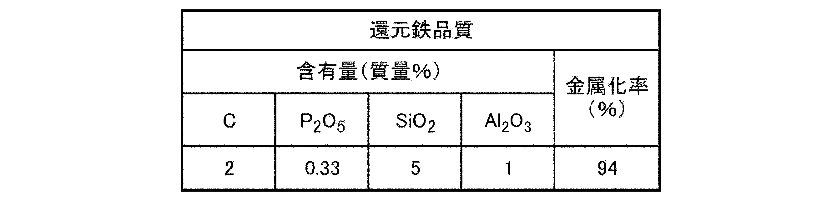
- the high-phosphorus reduced iron is reduced iron (DRI, HBI, etc.) obtained by reducing high-phosphate iron ore as a raw material, and has a P concentration of 0.15% by mass or more.
- the solid iron sources 100 are stacked along the furnace wall 12, and the slag bath surface 221 is exposed in the upper electrode facing space ⁇ .
- a flux 123 is supplied (see steps S3 and S4 in FIG. 4).
- the carbon material 121 is used as a reducing material and a recarburizing material for oxides (steelmaking slag 140, iron oxide in the iron-containing dust 103b, unreduced iron oxide in the reduced iron 103a, etc.). Coke, coal, charcoal, or the like can be used as the carbonaceous material 121 .
- the particle size of the carbonaceous material 121 is preferably 0.5 mm to 10 mm. If the carbonaceous material 121 has a particle size of 0.5 mm to 10 mm, it is not fine powder, so there is little scattering loss.
- the particle size is defined as the mesh size of a sieve through which particles can pass, and the particle size of 10 mm or less means that the particles can pass through a 10 mm sieve.
- the particle size of 80% by mass or more of the supplied carbonaceous material 121 should be 0.5 mm to 10 mm.
- a DC electric furnace is used as the electric furnace 10 .
- a strong downward flow is generated in the slag or molten iron just below the electrode, thereby feeding the carbonaceous material 121 into the molten iron below, and promoting the dissolution of the carbonaceous material 121 .
- the carbon material 121 is preferably supplied from a plurality of locations around the upper electrode 14 of the electric furnace 10 to the slag bath surface 221 formed in the upper electrode facing space ⁇ .
- the slag in the furnace (the slag inside the electric furnace 10) is reduced, and at the same time, the circulating flow of the slag quickly transports and dissolves the floating carbon material powder in the molten iron, Recarburization can be performed so that the C concentration of the molten iron is 2% or more.
- the horizontal distance from the upper electrode 14 to the periphery of the upper electrode 14 is within 1 m.
- the multiple locations are preferably two or more locations per electrode.
- one or more bottom blowers having a flow rate variable small diameter circle or flat gas flow path. It is preferable to provide a bottom blowing tuyere 11a1 for blowing inert gas into the electric furnace 10 at a maximum of 200 Nm 3 /h per tuyere 11a1.
- the upper limit of the distance from directly below the upper electrode 14 may be, for example, 5 m or 3 m.
- the reason why the upper limit of the bottom-blowing flow rate is limited to 200 Nm 3 /h or less is to suppress the erosion speed of the bottom-blowing tuyere 11a1 and reduce the frequency of tuyere replacement.
- the bottom-blown gas it is preferable to use nitrogen gas, which can maintain a reducing atmosphere in the electric furnace and is inexpensive.
- the carbonaceous material 121 floating on the slag bath surface 221 is easily combusted by air entering the electric furnace 10, it is effective to make the electric furnace 10 as closed as possible in order to prevent this.
- By eliminating the opening of the furnace body and preventing air intrusion it is possible to reduce the oxidation loss of the carbon material 121 remaining on the slag bath surface 221 in the furnace and improve the carburization efficiency.
- the component-adjusting flux 123 is a flux containing at least one of CaO, SiO 2 and Al 2 O 3 as a component composition.
- the slag components are adjusted, and the melting point and viscosity are controlled. should be reduced to ensure reactivity and fluidity. Therefore, in the present embodiment, the component adjusting flux 123 containing at least one of CaO, SiO 2 and Al 2 O 3 is charged into the electric furnace 10 .
- the electric furnace slag component after adding the carbonaceous material 121 and the component adjusting flux 123 in mass%, ⁇ T. Fe concentration: 5% or less, ⁇ CaO/SiO 2 concentration ratio: 1.0 to 1.3, ⁇ Al 2 O 3 concentration: 8 to 20% is preferably in the range of Even if the steelmaking slag 140 is not supplied, the component adjusting flux 123 is supplied.
- the oxides contained in the steelmaking slag 140 and the solid iron source 100 to be supplied It also varies depending on the components of After the oxide components contained in the steelmaking slag 140 or the solid iron source 100 are mixed with the component-adjusting flux 123, the components of the electric furnace slag may be within the above preferred range.
- the slag composition is adjusted to the optimum range by appropriately blending brick waste with an Al 2 O 3 concentration of 83% by mass and fly ash with an SiO 2 concentration of 59% by mass and an Al 2 O 3 concentration of 23% by mass, Slag dissolution can be favorably promoted.
- the component-adjusting flux 123 in addition to quicklime, silica sand, brick chips, and fly ash, sewage sludge ash, aluminum dross, and the like can be used. Also, the steelmaking slag itself can be used as the component-adjusting flux.
- the carbon material 121 and the component adjusting flux 123 are supplied toward the slag bath surface 221 exposed from the auxiliary material supply pipe 13b.
- Molten iron 210 produced inside the electric furnace 10 is tapped from the tapping hole 11b1. Also, the electric furnace slag 220 is discharged from the slag discharge hole 11b2. The oxides contained in the steelmaking slag 140 and the solid iron source 100 are reduced and reformed, and high-quality reduced slag equivalent to the blast furnace slag 42 is recovered as the electric furnace slag 220 . Since the electric furnace slag 220 has a lower concentration of FeO, P 2 O 5 and the like than before reduction, it can be used as a raw material for cement or a ceramic product, for example. In addition, since it has low expansibility, it can be used as a civil engineering material such as a roadbed material, an aggregate, and a stone material.
- the molten iron 210 tapped from the electric furnace 10 is high phosphorus hot metal with a high P concentration.
- the P concentration of the molten iron 210 is higher than 0.15%, the molten iron 210 is placed in the ladle 24 (see FIG. 3), and dephosphorization treatment is performed by ladle dephosphorization refining until the P concentration becomes 0.15% or less. to produce dephosphorized hot metal 310 and dephosphorized slag 320 (step S5 in FIG. 4). As shown in FIG.
- dephosphorization-treated hot metal 310 is sent to a steelmaking facility 51 comprising a hot metal desulfurization facility 52, a converter 53, and a secondary refining facility 54 to produce molten steel (step in FIG. 4).
- S6A After the molten iron 210 with a high P concentration is discharged from the electric furnace 10, it is dephosphorized in the ladle 24 to the P concentration level of the ordinary molten iron or less, thereby reducing the dephosphorization load in the converter 53 in the next step, and at the same time, A high-phosphate slag 321 with a high P 2 O 5 concentration can be obtained.
- the high phosphate slag 321 can be a phosphate fertilizer or phosphate product feedstock.
- the P 2 O 5 concentration of the dephosphorization slag 320 obtained by dephosphorization refining in the ladle is lower than the target value, it is supplied to the electric furnace 10 again to increase the P concentration of the molten iron 210, and the ladle Dephosphorization refining can further increase the P 2 O 5 concentration of the dephosphorization slag 320 . If the P 2 O 5 concentration is sufficiently high, it can be used as a phosphate fertilizer or phosphate raw material.
- the dephosphorization slag 320 formed in the ladle dephosphorization refining is recycled to the electric furnace 10 depending on the P 2 O 5 concentration, or is used as a high phosphate fertilizer or phosphate raw material as a high phosphate slag 321 ( See step S6B in FIG. 4).
- the usable range of low-grade iron ore with a high P concentration is expanded, and all the slag generated in the steelmaking facility 51 can be converted into slag equivalent to blast furnace slag with higher added value.
- valuable iron and phosphorus can be recovered and made into products such as iron sources and phosphate fertilizers.
- the P 2 O 5 concentration of the derinsing slag 320 is less than 8%, it is recycled to the electric furnace 10, and when the P 2 O 5 concentration of the derinsing slag 320 is 8% or more, P 2 O 5 , CaO, SiO 2 , and It is preferable to use a phosphate fertilizer containing MgO or a phosphate raw material.
- concentration of P 2 O 5 is set at 8% is that below that, the fertilizer effect as a phosphate fertilizer is remarkably reduced.
- the higher the P 2 O 5 content the more efficiently the product can be produced.
- Dephosphorization treatment method performed in ladle dephosphorization refining As a dephosphorization treatment method performed in ladle dephosphorization refining, as shown in FIG. It is preferable to blow 0.5 to 5 NL/t/min of gas from 23 or immersion lance 25 . Dephosphorization refining is performed by blowing oxygen from the lance 21 and supplying iron oxide.
- the basicity of the slag is 2 or less, and the fluorite containing F (fluorine) that inhibits the fertilizer effect is not used. Dephosphorization is possible.
- a portion of the lime-based dephosphorization agent is desirably projected by the fuel burner 22, and the lime-based dephosphorization is performed. The agent powder is melted by passing it through the combustion flame of the fuel burner 22 .
- the molten iron 210 is stirred, the dephosphorization reaction efficiency is improved, the thermal efficiency of the fuel burner 22 is improved, and the slag Inside T. It becomes possible to easily control the Fe concentration level.
- the nitrogen gas blowing rate By setting the nitrogen gas blowing rate to a suitable range of 5 NL/t/min or less, the T.E. The Fe concentration can be set within a suitable range. Further, by setting the nitrogen gas blowing speed to an appropriate flow rate of 0.5 NL/t/min or more, the surface renewal of the slag bath can be promoted by gas stirring, and the thermal efficiency of the fuel burner 22 can be improved.
- FIG. 1 shows a schematic diagram of the hot metal production process of the present application (Fig. 1(B)) in comparison with a conventional example (Fig. 1(A)).
- FIG. 2 shows a schematic diagram of an electric furnace for hot metal production
- FIG. 3 shows a schematic diagram of a dephosphorization treatment apparatus.
- iron-containing scrap 101, reduced iron 103a, iron-containing dust 103b, molten steelmaking slag 140, carbon material 121, and component-adjusting flux 123 are supplied to the electric furnace 10 by respective methods, A closed stationary DC electric furnace that melts and reduces the carbon source from the carbon material 121 to produce molten iron 210 and reduced electric furnace slag 220; ⁇ By dephosphorizing the obtained hot metal 210 (high phosphorus hot metal), the dephosphorized hot metal 310 (ordinary hot metal) that can be recycled to the converter 53 and high phosphoric acid as a phosphate fertilizer or ladle phosphate raw material a ladle dephosphorization refining facility 57 that produces slag 321; It uses the manufacturing process of hot metal and molten steel using
- the electric furnace 10 has a maximum power capacity of 200 MW, three upper electrodes 14, and a conductive refractory electrode directly below the upper electrode 14 as a lower electrode 15 (furnace bottom refractory electrode) separated by a non-conductive refractory, A stationary DC electric furnace having two tapping holes 11b1 and two slag tapping holes 11b2 with different height positions (levels) was used. Table 1 shows the specifications of the electric furnace 10.
- the reduced iron 103a and the iron-containing dust 103b were supplied by selectively using 12 solid iron source supply pipes 13a provided in the vicinity of the furnace wall 12 on the furnace cover 13.
- the iron-containing scrap 101 was supplied by a chute by opening the respective lids 13c1 of the two supply ports 13c provided in the furnace lid 13, and supplied so as to be piled up along the furnace wall 12 of the electric furnace 10 ( See Figure 2).
- carbonaceous powder, which serves as a reducing material and a recarburizing material, and flux 123 for component adjustment such as fly ash, silica sand, and brick shavings are supplied to six auxiliary raw material supply pipes 13 b provided on the furnace lid 13 near the upper electrode 14 .
- the iron-containing scrap 101 was continuously supplied to the exposed surface of the slag bath surface 221 in the furnace except when the lid 13c1 of the supply port 13c for supplying the iron-containing scrap 101 was open.
- the slag discharged from the converter 53 (steelmaking slag 140) is placed in the slag pot 16, and fed into the electric furnace 10 from the supply port 13c in a molten state. (see Figure 2).
- the reduced iron 103a or the iron-containing scrap 101 arranged in a pile was supplied from the supply port 13c.
- the electric furnace 10 is continuously operated, and 300 tons of molten iron 210 is always present in the furnace as a seed bath.
- a part of the electric furnace slag 220 is directly subjected to water granulation treatment and used as a raw material for cement.
- the slag discharged from the tap hole 11b1 along with the hot metal 210 is separated by a skimmer and subjected to a slow cooling treatment to be used as silica fertilizer or a civil engineering material.
- arc irradiation by the upper electrode 14 was continued.
- a A bottom blowing tuyere 11a1 was provided at a total of eight locations at a position 3 m away from directly below, and gas was blown in.
- the molten iron 210 discharged from the electric furnace 10 was received in a ladle 24 with a capacity of 300 tons and processed in a ladle dephosphorization refining equipment 57 (see FIG. 3).
- Table 2 shows the specifications of the ladle dephosphorization device 20 .
- ⁇ Equipment for upward addition of lime-based dephosphorizing agent and iron oxide - Lance 21 for oxygen top blowing, ⁇ Fuel burner 22 (LPG burner lance) capable of projecting powder, and ⁇ Bottom porous plug 23 (bottom blowing porous tuyere) have.
- the hot metal 310 after dephosphorization treatment obtained in the ladle dephosphorization refining equipment 57 has the same P concentration as that of normal hot metal, so it was conveyed to the steelmaking equipment 51 as it is. Also, since the derinsed slag 320 has a relatively high (P 2 O 5 ) concentration, it was used as a phosphate fertilizer. If a fertilizer with a higher (P 2 O 5 ) concentration is desired, the dephosphorization slag 320 may be supplied to the electric furnace 10 for reduction to increase the P concentration in the hot metal.
- dephosphorization-treated hot metal 310 obtained in the ladle dephosphorization refining facility 57 was desulfurized in the hot metal desulfurization facility 52 and supplied to the converter 53 .
- No blast furnace hot metal was supplied to the converter 53 .
- Decarburization and finish dephosphorization were performed in a converter 53, and casting was performed in a continuous casting facility 56 via a secondary refining facility 54 (see FIG. 1).
- the C concentration in the hot metal supplied to the converter 53 is 2.0%, which is considerably lower than that of the blast furnace hot metal.
- Case 1 to Case 4 shown in Table 4 were treated.
- high phosphate iron ore-derived DRI having the components shown in Table 3 was used.
- component-adjusting flux 123 to be supplied to the electric furnace 10 silica sand is used as the SiO 2 source, and alumina brick dust is used as the Al 2 O 3 source.
- the supply unit consumption is described in the “Al 2 O 3 ” column.
- the molten iron 210 was dephosphorized in the ladle dephosphorization refining equipment 57 until the P concentration reached 0.10%. Then, the obtained dephosphorized hot metal 310 was sent to the steelmaking facility 51 . After this dephosphorization treatment, the molten iron 310 was supplied to the converter 53, and as a result of the converter blowing, the P concentration of the molten steel was 0.015%. Since the (P 2 O 5 ) concentration of the dephosphorization slag 320 in the ladle dephosphorization refining equipment 57 was 8.9%, it was used as a phosphate fertilizer.
- the change in concentration in the entire process is as follows. ⁇ P concentration of hot metal 210: 0.35%, -P concentration of the derinsing slag 320: 0.10%, (P 2 O 5 ) concentration of the derinsing slag 320: 8.9%, ⁇ Concentration of P in steel output from converter: 0.015%
- the molten iron 310 was supplied to the converter 53, and as a result of the converter blowing, the P concentration of the molten steel was 0.015%. Since the (P 2 O 5 ) concentration of the dephosphorization slag 320 in the ladle dephosphorization refining was 4.5%, it was recycled to the electric furnace 10 for the next charge.
- the change in concentration in the entire process is as follows. ⁇ P concentration of hot metal 210: 0.16%, -P concentration of the derinsing slag 320: 0.10%, (P 2 O 5 ) concentration of derinsing slag 320: 4.5%, ⁇ Concentration of P in steel output from converter: 0.015%
- the molten iron 310 was supplied to the converter 53, and as a result of the converter blowing, the P concentration of the molten steel was reduced to 0.010%, and ultra-low phosphorus steel could be produced. Since the (P 2 O 5 ) concentration of the dephosphorization slag 320 in the ladle dephosphorization refining was 3.7%, it was recycled to the electric furnace 10 for the next charge.
- the change in concentration in the entire process is as follows.
Abstract
Description
本願は、2021年9月30日に、日本に出願された特願2021-161078号に基づき優先権を主張し、その内容をここに援用する。
さらに、上記電気炉から回収された高リン溶銑に対して、取鍋において脱リン処理を施して、溶銑中のリンを酸化させてスラグ中に移行させる。これにより、高リン溶銑が高リン酸スラグと低リン溶銑とに分離される。高リン酸スラグは、リン酸肥料及びリン酸原料として製品化することができる。また、低リン溶銑は、製鋼工程にリサイクルされ、高炉溶銑と混合した上で転炉に投入される。
(1)本発明の一態様は、固定式直流電気炉を用いた溶銑製造方法であって、炉内で、スラグ浴面と、炉蓋より挿入された上部電極の下端との間の高さ位置における、前記上部電極の外周からの水平方向離間距離が、前記上部電極の直径の0.5倍以内である空間を上部電極対向空間と定義し、前記炉内で、前記スラグ浴面の高さ位置よりも上の高さ位置における、炉壁の内壁面からの水平方向離間距離が、前記炉壁と前記上部電極対向空間との最短距離以内である空間を炉内周壁空間と定義したとき、前記炉内周壁空間に固体鉄源が存在する状態で、且つ、前記上部電極対向空間に前記固体鉄源が存在しない状態で、副原料を前記固定式直流電気炉に供給し、質量%で、C濃度が2~4%、温度が1400℃~1550℃である溶銑を出銑孔から出銑する。
(2)上記(1)に記載の溶銑製造方法では、前記炉内周壁空間における前記固体鉄源の頂部が、前記上部電極の下端よりも高い位置に存在してもよい。
(3)上記(1)又は(2)に記載の溶銑製造方法では、前記炉内周壁空間の全周に沿って前記固体鉄源が存在してもよい。
(4)上記(1)~(3)のいずれか一項に記載の溶銑製造方法では、前記固定式直流電気炉は、二本以上の前記上部電極と、前記固定式直流電気炉の底部の耐火物内に設けられた二本以上の下部電極と、を有し、前記固定式直流電気炉を平面視したとき、前記二本以上の下部電極は、前記二本以上の上部電極に対応する位置に設けられてもよい。
(6)上記(5)に記載の溶銑製造方法では、前記固体鉄源を供給するための供給口が前記炉内周壁空間の上に配置され、前記供給口から、前記固体鉄源を積載した固体鉄源装入器具を用いて、前記固体鉄源を供給してもよい。
(7)上記(1)~(6)のいずれか一項に記載の溶銑製造方法では、前記固体鉄源が、鉄含有スクラップ、還元鉄、及び、鉄含有ダスト、の少なくとも一種であってもよい。
(8)上記(1)~(7)のいずれか一項に記載の溶銑製造方法では、前記固体鉄源が少なくとも還元鉄を含み、前記還元鉄は、水素ガス、天然ガス、及び、COガスの少なくとも一種を用いて鉄鉱石を還元することによりC濃度が0~4質量%とされた還元鉄であり、前記還元鉄は、DRI又はHBIであってもよい。
(10)上記(9)に記載の溶銑製造方法では、前記副原料が、粒径0.5mm~10mmの炭材であり、前記炭材を、前記上部電極の周辺の複数個所から前記上部電極対向空間に形成された前記スラグ浴面に供給してもよい。
(11)上記(1)~(10)のいずれか一項に記載の溶銑製造方法では、製鋼スラグを前記固定式直流電気炉に供給してもよい。
(12)上記(11)に記載の溶銑製造方法では、前記製鋼スラグとして、転炉スラグ、溶銑脱硫スラグ、二次精錬スラグ、及び、脱リンスラグ、の少なくとも一種のスラグを用い、前記製鋼スラグを、溶融状態で、前記炉内周壁空間に存在する前記固体鉄源に供給してもよい。
(14)上記(1)~(13)のいずれか一項に記載の溶銑製造方法では、質量%で、T.Fe濃度が5%以下、CaO/SiO2濃度比が1.0~1.3、Al2O3濃度が8~20%である電気炉スラグを出滓孔から排出してもよい。
(15)上記(1)~(14)のいずれか一項に記載の溶銑製造方法では、前記溶銑のP濃度が0.15%より高い場合に、前記溶銑のP濃度が0.15%以下になるまで取鍋脱リン精錬による脱リン処理を施してもよい。
本実施形態に係る溶銑製造方法で用いる固定式直流電気炉10(以下、電気炉10)の一例について以下説明する。
図2に示すように、電気炉10は、下部11と、炉壁12と、炉蓋13と、上部電極14と、下部電極15により構成される。
底部11aには、電気炉10の内部にガスを吹き込むための底吹羽口11a1が設けられている。
壁部11bには、溶銑210を出銑する出銑孔11b1と電気炉スラグ220を排出する出滓孔11b2とが設けられている。
炉壁12は、電気炉10の下部11の壁部11bの上端に取り付けられている。
また、炉蓋13は、炉壁12の上端から上方に向かうに連れて電気炉10の内部側に傾斜するように延在する傾斜部分13Aと、傾斜部分13Aの上端に連なり水平方向に延在する水平部分13Bとにより構成されている。
供給口13cとダクト連結口13dは、炉蓋13の傾斜部分13Aを貫通するように設けられる。
供給口13cには、その開口部と開閉するための蓋13c1が設けられ、ダクト連結口13dには電気炉10の内部のガスを吸引するためのダクト17が連結される。
尚、炉蓋13の形状は一例に過ぎず、例えば、供給口13cは、水平部分13Bに設けられてもよい。
また、電気炉10の内部でスラグ浴面の高さ位置よりも上の高さ位置における、炉壁12の内壁面からの水平方向離間距離が、「炉壁12と上部電極対向空間αとの最短距離」以内である空間を炉内周壁空間βと定義する。
また、図2において、(A)はA-A矢視正面断面図、(B)はB-B矢視側面断面図、(C)はC-C矢視側面断面図である。
さらに、電気炉10は、直流電気炉を採用することで電極数を減らし、炉蓋13に固体鉄源供給管13a、副原料供給管13b、供給口13cを配置するための有効スペースを確保することにより、一つの電気炉10に多種多様な原料を供給することが可能となる。
また、傾動式電気炉では通電と止電を繰り返すため、生産性が低下するが、本実施形態で用いる電気炉10は固定式であって、溶銑210を出銑する出銑孔11b1と電気炉スラグ220を排出する出滓孔11b2を用いるので、効率よく連続的に溶銑210を製造することが可能になる。
また、電気炉10は、空気侵入を実質的に遮断可能に構成された密閉型の電気炉で、炉床からの高さの異なる出銑孔11b1と出滓孔11b2を具備することが好ましい。
本実施形態に係る溶銑製造方法で適用する電気炉10として固定式直流電気炉を用いることから、上部電極14の電極数は最低で一本から可能である。それに対して、二本以上の上部電極14と各上部電極14に対応した下部電極15(炉底耐火物電極)を具備することにより、直流電気炉の上部電極14を複数本配置し、それに合わせて炉形状及びサイズを決定することにより、電源容量の増加を容易にすることができ、高炉55を代替する規模の溶銑製造型の電気炉が可能となる。
また、炉体の開口部を実質的になくし、空気侵入を抑制することによって、炉内のスラグ浴面221に滞留する炭材121の酸化ロスを低減し、加炭効率を向上させることができる。例えば、30インチの直流型の上部電極14を三本、直線状に配置し、炉形状を直方体に近い形状とすることによって、電源容量200MWの規模を実現し、大型高炉の2分の1の規模に当たる200万t/yの出銑能力を持たせることができる。
電気炉10には、固体鉄源100として、鉄含有スクラップ101、還元鉄103a、及び、鉄含有ダスト103bの三つの原料のうちの少なくとも一種を供給する(図4のステップS1参照)。すなわち、固体鉄源100として、鉄含有スクラップ101のみ、還元鉄103aのみ、又は、鉄含有ダスト103bのみを用いてもよく、また、固体鉄源100として、鉄含有スクラップ101、還元鉄103a、及び、鉄含有ダスト103bの内の二種又は全てを混合して用いてもよい。固体鉄源100は、固体鉄源供給管13a又は供給口13cから供給される。
鉄含有ダスト103bとしては、転炉ダストを用いることができる。
一方、供給口13cからは、主に、個々のサイズが比較的大きく、固体鉄源供給管から安定的に供給し難い固体鉄源100(例えば柱状の場合、最大長が100mm超の固体鉄源100)である鉄含有スクラップ101(例えば、ヘビー屑)を電気炉10に供給する。
例えば、個々のサイズが比較的大きい鉄含有スクラップ101は、下記の手順で電気炉10に供給することができる。
(1)固体鉄源装入器具18に鉄含有スクラップ101を積載する。
(2)そして、供給口13cの蓋13c1を開いて、スラグ浴面221を維持したまま、電気炉10の炉内周壁空間βに固体鉄源装入器具18を介して鉄含有スクラップ101を供給する。
尚、個々のサイズが比較的大きい鉄含有スクラップ101に限らず、個々のサイズが比較的小さい還元鉄103a及び鉄含有ダスト103b等の固体鉄源100についても、上記の手順で電気炉10に供給口13cから供給することができる。一方、鉄含有スクラップ101も固体鉄源供給管13aから投入可能なサイズであれば、固体鉄源供給管13aから投入してもよい。
また、鉄含有ダスト103bの供給方法として、
(1)造粒して固体鉄源供給管13aから供給すること、
(2)大塊の脱水ケーキのまま鉄含有スクラップ101と一緒に供給口13cから供給すること、または、
(3)酸化鉄粉体として、炭材粉と共に副原料供給管13bからスラグ浴面221に供給すること、
も可能である。
供給口13cも同様に、供給する固体鉄源100が炉壁12に沿って山積みされるように配置される。このため、供給口13cは、炉内周壁空間βの上方に配置されていることが好ましい。
供給された固体鉄源100は、固体鉄源供給管13a及び供給口13cからの供給後においていずれも炉壁12に沿って山積み(すなわち、炉内周壁空間βに存在するように配置)される。
一方、電気炉10の上部電極対向空間αには固体鉄源100が存在しない、すなわち、電気炉スラグ220のスラグ浴面221が露出している。このような、固体鉄源100が存在しない上部電極対向空間αのスラグ浴面221は、上部電極14と、下部電極15との間の領域に形成される。
尚、木炭などの炭材を内装したペレットから製造した還元鉄を還元鉄103aとして用いてもよい。
電気炉10には、製鋼スラグ140を供給することができる(図4のステップS2参照)。
また、供給する製鋼スラグ140が固化状態の場合は、供給口13c及び固体鉄源供給管13a、副原料供給管13bのいずれか一つ以上から供給してもよい。
また、製鋼スラグ140のうち、溶銑脱硫スラグ及び二次精錬スラグに含まれるCaOとAl2O3は電気炉スラグ220の成分調整に利用できる。
このように製鋼設備51で発生する製鋼スラグ140はすべて電気炉10に供給することが可能である。
結果として生成した電気炉スラグ220は、高炉スラグ42と同等の組成に調整することで、高炉セメント等の原料として利用することができる。
尚、高リン還元鉄とは、高リン鉄鉱石を原料として還元した還元鉄(DRIやHBIなど)であり、P濃度が0.15質量%以上のものを意味している。
炭材121は、酸化物(製鋼スラグ140、鉄含有ダスト103bの中の酸化鉄、還元鉄103aの中の未還元酸化鉄など)の還元材及び加炭材として用いられる。炭材121には、コークス、石炭、木炭などを用いることができる。
炭材121の粒径は0.5mm~10mmであることが好ましい。炭材121が、粒径0.5mm~10mmであれば微粉ではないため飛散ロスが少なく、また小粒径のため反応速度が速い。ここで、粒径とは、粒子が通過できる篩の網目で定義し、粒径が10mm以下とは、10mmの篩を通過できるものとする。また、供給する炭材121の80質量%以上の粒径が0.5mm~10mmであればよい。
炭材121を添加することにより、酸化物の還元反応を進行させ、また、溶鉄に加炭して溶鉄のC濃度を上昇させる。
そして、C濃度が2~4質量%以上、温度が1400℃~1550℃である溶銑210とし、出銑孔11b1から出銑する。これにより、溶銑をそのまま、あるいは溶銑の脱リン処理を行った上で、単独で製鋼工程に供給することができる。
本実施形態では、電気炉10として直流電気炉を用いる。直流電気炉においては、電極直下のスラグや溶鉄中に下向きの強い流れを起こし、それによって炭材121を下方の溶鉄に送り込み、炭材121の溶解を促進することができる。
また、本実施形態では、炭材121を電気炉10の上部電極14の周辺の複数個所から、上部電極対向空間αに形成されたスラグ浴面221に供給することが好ましい。このように炭材121を供給することにより、炉内スラグ(電気炉10の内部のスラグ)を還元すると同時に、当該スラグの循環流動により浮遊する炭材粉を速やかに溶鉄に運搬、溶解させ、溶鉄のC濃度が2%以上となるよう加炭することができる。
さらに、直流電気炉を用いることによって、電磁力により上部電極14の直下のスラグ及び溶鉄に下方へ向かう流れが形成され、スラグ浴に供給した炭材粉を下方の溶鉄に運搬しやすくなる。炭材供給位置に関し、上部電極14の周辺とは、上部電極14からの水平距離が1m以内が好ましい。複数個所とは、電極一本あたり二個所以上が好ましい。
底吹流量の上限を200Nm3/h以下に限定する理由は、底吹羽口11a1の溶損速度を抑え、羽口交換の頻度を低減するためである。底吹きガスとしては、電気炉内を還元雰囲気に維持でき、かつ安価な窒素ガスを用いることが好ましい。
成分調整用フラックス123は、成分組成としてCaO、SiO2、Al2O3の少なくとも一種を含むフラックスである。
製鋼スラグ140や固体鉄源100に含有される酸化物の溶解、還元を速やかに進行させ、電気炉スラグ220を出滓孔11b2から円滑に排出するために、スラグ成分を調整し、融点と粘性を低下させて反応性と流動性を確保する必要がある。そこで、本実施形態では、電気炉10の内部には、成分組成としてCaO、SiO2、Al2O3の少なくとも一種を含む成分調整用フラックス123を投入する。炭材121及び成分調整用フラックス123を添加後の電気炉スラグ成分として、質量%で、
・T.Fe濃度:5%以下、
・CaO/SiO2濃度比:1.0~1.3、
・Al2O3濃度:8~20%
の範囲とすることが好ましい。
尚、製鋼スラグ140を供給しない場合であっても、成分調整用フラックス123は供給する。
・CaO濃度95質量%の生石灰、
・SiO2濃度99質量%の珪砂、
・Al2O3濃度83質量%のレンガ屑、および
・SiO2濃度59質量%、Al2O3濃度23質量%のフライアッシュ
を適切に配合することにより、スラグ組成を最適範囲に調整し、スラグ溶解を好適に促進させることができる。成分調整用フラックス123としては、生石灰、珪砂、レンガ屑、フライアッシュの他に、下水汚泥灰、アルミドロス、等を用いることができる。また、製鋼スラグ自体を成分調整用フラックスとして用いることもできる。
製鋼スラグや高リン還元鉄を用いた場合、電気炉10から出銑した溶銑210は、P濃度の高い高リン溶銑である。この溶銑210のP濃度が0.15%より高い場合、溶銑210を取鍋24に収容し(図3参照)、P濃度が0.15%以下となるまで取鍋脱リン精錬による脱リン処理を施して脱リン処理後溶銑310と脱リンスラグ320を製造する(図4のステップS5)。
図1の(B)に示すように、脱リン処理後溶銑310は溶銑脱硫設備52、転炉53、および二次精錬設備54からなる製鋼設備51に送って溶鋼を製造する(図4のステップS6A参照)。
P濃度の高い溶銑210を、電気炉10から排出後、取鍋24で普通溶銑のP濃度レベル以下まで脱リンすることで、次工程の転炉53での脱リン負荷軽減を図ると同時に、P2O5濃度の高い高リン酸スラグ321を得ることができる。高リン酸スラグ321はリン酸肥料やリン酸製品原料とすることができる。
よりP濃度を下げるために高塩基度(例えば、塩基度2.5以上)のスラグを必要とする場合、望ましくは石灰系脱リン剤の一部を燃料バーナー22で投射し、石灰系脱リン剤の粉末を燃料バーナー22の燃焼炎中を通過させることによって溶融する。また、鍋底ポーラスプラグ23または浸漬ランス25から0.5~5NL/t/minの撹拌ガスを吹き込むことにより、溶銑210が撹拌され、脱リン反応効率の向上、燃料バーナー22の熱効率の向上、スラグ中のT.Fe濃度レベルの制御を容易に行うことが可能となる。窒素ガス吹き込み速度を5NL/t/min以下の好適範囲とすることにより、スラグ中のT.Fe濃度を好適範囲とすることができる。また、窒素ガス吹き込み速度を0.5NL/t/min以上の適正流量とすることにより、スラグ浴の表面更新をガス撹拌で促進し、燃料バーナー22の熱効率を向上させることができる。
・炭材121からの炭素源により溶解還元して溶銑210と還元した電気炉スラグ220を製造する密閉型の固定式直流電気炉と、
・得られた溶銑210(高リン溶銑)を脱リンすることによって、転炉53にリサイクル可能な脱リン処理後溶銑310(普通溶銑)とリン酸肥料または取鍋リン酸原料となる高リン酸スラグ321とを製造する取鍋脱リン精錬設備57と、
を用いる溶銑及び溶鋼の製造工程を用いている。
電気炉10として電源容量最大200MW、上部電極14を三本、下部電極15(炉底耐火物電極)として上部電極14の直下に導電性耐火物電極を備えて非導電性耐火物で分離し、高さ位置(レベル)の異なる出銑孔11b1と出滓孔11b2を二個ずつ有する固定式直流電気炉を用いた。電気炉10の諸元を表1に示す。

また、鉄およびリンの回収と電気炉スラグ220の成分調整を目的として、転炉53から排出されたスラグ(製鋼スラグ140)をスラグ鍋16に収容し、電気炉10に供給口13cから溶融状態で供給した(図2参照)。具体的には、溶融スラグと溶銑210との直接反応を回避し、突沸を防止するために、山積み状に配置された還元鉄103aまたは鉄含有スクラップ101に向けて、供給口13cから供給した。
また、溶銑210と随伴して出銑孔11b1から排出されるスラグは、スキンマーで分離して徐冷処理を行い、ケイカル肥料や土木用材料とした。出銑と出滓の際、上部電極14によるアーク照射は継続して実施した。
・石灰系脱リン剤と酸化鉄を上方添加する装置、
・酸素上吹き用のランス21、
・粉体を投射できる燃料バーナー22(LPGバーナーランス)、および
・鍋底ポーラスプラグ23(底吹ポーラス羽口)
が備わっている。
表4に示すCase1とCase3では石灰系脱リン剤供給と酸素上吹きを行い、酸化鉄供給によって冷却して温度調節を行った。
また、Case2とCase4では塩基度が2.0とやや高かったので、酸素上吹を途中で中止し、石灰系脱リン剤をバーナーで投射しながら酸化鉄を供給し、脱リン剤粒子にP2O5を吸収させた。

表4に示すCase1~Case4の処理を行った。電気炉10へ供給する主原料のうち、還元鉄103aについては、いずれも表3に示す成分の高リン鉄鉱石由来のDRIを用いた。電気炉10に供給する成分調整用フラックス123については、SiO2源として珪砂を用い、Al2O3源としてアルミナれんが屑を用い、それぞれ表4の「成分調整用フラックス」欄の「SiO2」「Al2O3」欄に供給原単位を記載した。
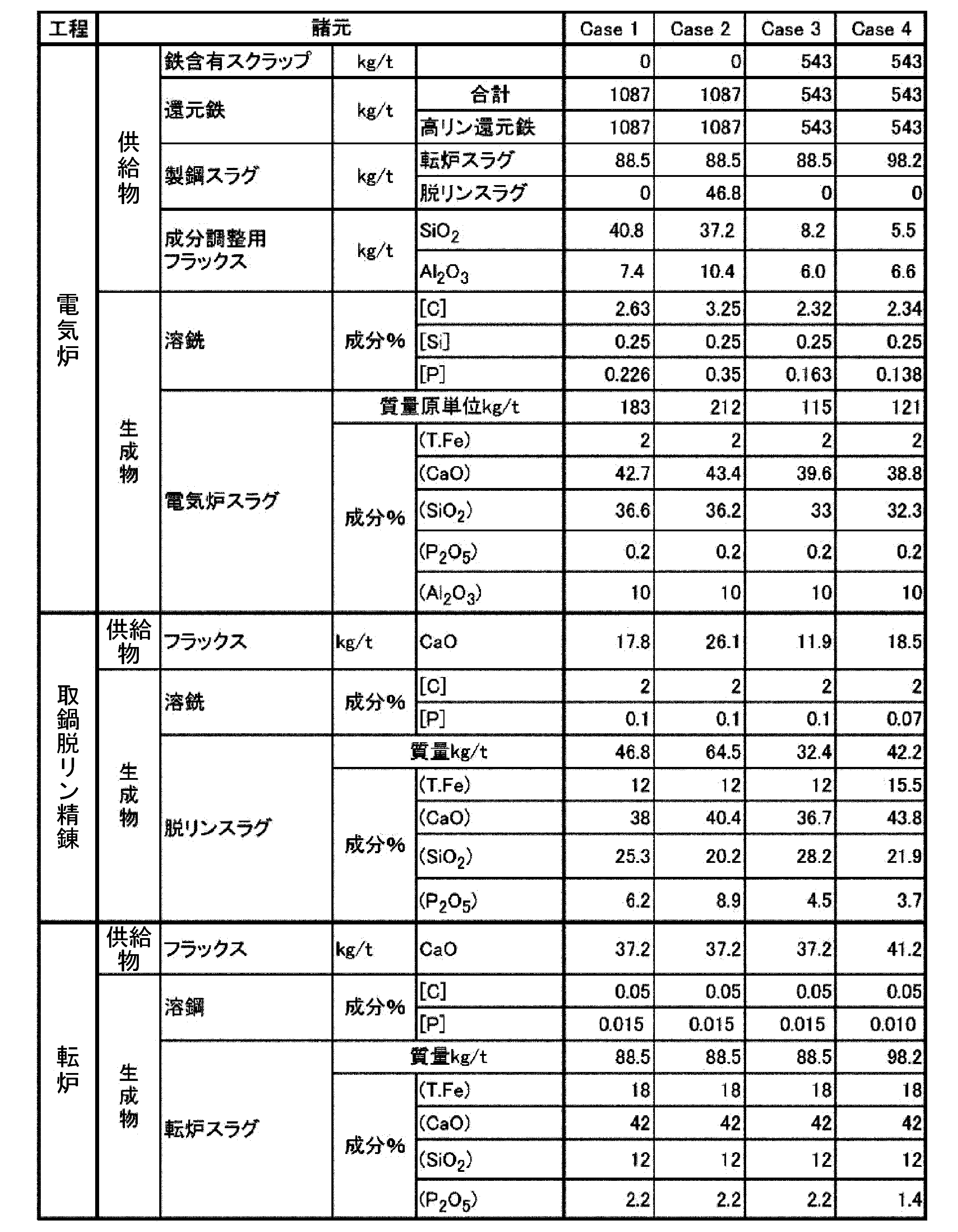
固体鉄源100として、表3に示す還元鉄103a(高リン鉄鉱石由来のDRI)を100%使用し、製鋼スラグ140として表4のCase1の転炉工程「スラグ」に示す成分と原単位の転炉スラグを溶融状態で全量、電気炉10に供給した。
電気炉精錬で得られた生成物としての溶銑210のP濃度は0.23%であったので、取鍋脱リン精錬設備57で溶銑210をP濃度が0.10%になるまで脱リンして、得られた脱リン処理後溶銑310を製鋼設備51に送った。
この脱リン処理後溶銑310を転炉53に供給し、転炉吹錬の結果、溶鋼のP濃度は0.015%であった。
取鍋脱リン精錬設備57での脱リンスラグ320の(P2O5)濃度は6.2%であったので、次チャージであるCase2において電気炉10にリサイクルした。
全体工程での濃度の推移は以下のとおりである。
・溶銑210のP濃度:0.23%、
・脱リンスラグ320のP濃度:0.10%、
・脱リンスラグ320の(P2O5)濃度:6.2%、
・転炉出鋼P濃度:0.015%
固体鉄源100として、表3に示す還元鉄103a(高リン鉄鉱石由来のDRI)を100%使用し、製鋼スラグ140として表4のCase2の転炉工程「スラグ」に示す成分と原単位の転炉スラグを溶融状態で全量、電気炉10に供給した。
また、前チャージであるCase1の脱リンスラグ320も電気炉10に供給し、リン酸を富化した。
電気炉精錬で得られた生成物としての溶銑210のP濃度は0.35%であったので、取鍋脱リン精錬設備57で溶銑210をP濃度が0.10%になるまで脱リンして、得られた脱リン処理後溶銑310を製鋼設備51に送った。
この脱リン処理後溶銑310を転炉53に供給し、転炉吹錬の結果、溶鋼のP濃度は0.015%であった。
取鍋脱リン精錬設備57での脱リンスラグ320の(P2O5)濃度は8.9%であったので、リン酸肥料として使用した。
全体工程での濃度の推移は以下のとおりである。
・溶銑210のP濃度:0.35%、
・脱リンスラグ320のP濃度:0.10%、
・脱リンスラグ320の(P2O5)濃度:8.9%、
・転炉出鋼P濃度:0.015%
固体鉄源100として、表3に示す還元鉄103a(高リン鉄鉱石由来のDRI)を50%、鉄含有スクラップ101を50%使用し、製鋼スラグ140として表4のCase3の転炉工程「スラグ」に示す成分と原単位の転炉スラグを溶融状態で全量、電気炉10に供給した。
電気炉精錬で得られた生成物としての溶銑210のP濃度は0.16%であったので、取鍋脱リン精錬設備57で溶銑210をP濃度が0.10%になるまで脱リンして、製鋼設備51に送った。
この脱リン処理後溶銑310を転炉53に供給し、転炉吹錬の結果、溶鋼のP濃度は0.015%であった。
取鍋脱リン精錬での脱リンスラグ320の(P2O5)濃度は4.5%であったので、次チャージの電気炉10にリサイクルした。
全体工程での濃度の推移は以下のとおりである。
・溶銑210のP濃度:0.16%、
・脱リンスラグ320のP濃度:0.10%、
・脱リンスラグ320の(P2O5)濃度:4.5%、
・転炉出鋼P濃度:0.015%
固体鉄源100として、表3に示す還元鉄103a(高リン鉄鉱石由来のDRI)を50%、鉄含有スクラップ101を50%使用し、製鋼スラグ140として表4のCase4の転炉工程「スラグ」に示す成分と原単位の転炉スラグを溶融状態で全量、電気炉10に供給した。
電気炉精錬で得られた生成物としての溶銑210のP濃度は0.14%であったので、取鍋脱リン精錬設備57で溶銑210をP濃度が0.07%になるまで脱リンして、製鋼設備51に送った。
この脱リン処理後溶銑310を転炉53に供給し、転炉吹錬の結果、溶鋼のP濃度を0.010%まで下げ、極低リン鋼を溶製することができた。
取鍋脱リン精錬での脱リンスラグ320の(P2O5)濃度は3.7%であったので、次チャージの電気炉10にリサイクルした。
全体工程での濃度の推移は以下のとおりである。
・溶銑210のP濃度:0.14%、
・脱リンスラグ320のP濃度:0.07%、
・脱リンスラグ320の(P2O5)濃度:3.7%、
・転炉出鋼P濃度:0.010%
α 上部電極対向空間
β 炉内周壁空間
11 下部
11a 底部
11a1 底吹羽口
11b 壁部
11b1 出銑孔
11b2 出滓孔
12 炉壁
13 炉蓋
13A 傾斜部分
13B 水平部分
13a 固体鉄源供給管
13b 副原料供給管
13c 供給口
13c1 蓋
13d ダクト連結口
14 上部電極
15 下部電極(炉底耐火物電極)
16 スラグ鍋
17 ダクト
18 固体鉄源装入器具
20 取鍋脱リン装置
21 ランス
22 燃料バーナー
23 鍋底ポーラスプラグ
24 取鍋
25 浸漬ランス
42 高炉スラグ
51 製鋼設備
52 溶銑脱硫設備
53 転炉
54 二次精錬設備
55 高炉
56 連続鋳造設備
57 取鍋脱リン精錬設備
100 固体鉄源
101 鉄含有スクラップ
103a 還元鉄
103b 鉄含有ダスト
121 炭材
123 成分調整用フラックス
140 製鋼スラグ
210 溶銑
220 電気炉スラグ
221 スラグ浴面
310 脱リン処理後溶銑
320 脱リンスラグ
321 高リン酸スラグ
Claims (15)
- 固定式直流電気炉を用いた溶銑製造方法であって、
炉内で、スラグ浴面と、炉蓋より挿入された上部電極の下端との間の高さ位置における、前記上部電極の外周からの水平方向離間距離が、前記上部電極の直径の0.5倍以内である空間を上部電極対向空間と定義し、
前記炉内で、前記スラグ浴面の高さ位置よりも上の高さ位置における、炉壁の内壁面からの水平方向離間距離が、前記炉壁と前記上部電極対向空間との最短距離以内である空間を炉内周壁空間と定義したとき、
前記炉内周壁空間に固体鉄源が存在する状態で、且つ、前記上部電極対向空間に前記固体鉄源が存在しない状態で、副原料を前記固定式直流電気炉に供給し、
質量%で、C濃度が2~4%、温度が1400℃~1550℃である溶銑を出銑孔から出銑する
ことを特徴とする溶銑製造方法。 - 前記炉内周壁空間における前記固体鉄源の頂部が、前記上部電極の下端よりも高い位置に存在する
ことを特徴とする請求項1に記載の溶銑製造方法。 - 前記炉内周壁空間の全周に沿って前記固体鉄源が存在する
ことを特徴とする請求項1又は2に記載の溶銑製造方法。 - 前記固定式直流電気炉は、
二本以上の前記上部電極と、
前記固定式直流電気炉の底部の耐火物内に設けられた二本以上の下部電極と、
を有し、
前記固定式直流電気炉を平面視したとき、前記二本以上の下部電極は、前記二本以上の上部電極に対応する位置に設けられている
ことを特徴とする請求項1又は2に記載の溶銑製造方法。 - 前記固体鉄源を供給するための供給口又は固体鉄源供給管が前記炉内周壁空間の上に配置されている
ことを特徴とする請求項1又は2に記載の溶銑製造方法。 - 前記固体鉄源を供給するための供給口が前記炉内周壁空間の上に配置され、
前記供給口から、前記固体鉄源を積載した固体鉄源装入器具を用いて、前記固体鉄源を供給する
ことを特徴とする請求項5に記載の溶銑製造方法。 - 前記固体鉄源が、鉄含有スクラップ、還元鉄、及び、鉄含有ダスト、の少なくとも一種である
ことを特徴とする請求項1又は2に記載の溶銑製造方法。 - 前記固体鉄源が少なくとも還元鉄を含み、
前記還元鉄は、水素ガス、天然ガス、及び、COガスの少なくとも一種を用いて鉄鉱石を還元することによりC濃度が0~4質量%とされた還元鉄であり、
前記還元鉄は、DRI又はHBIである
ことを特徴とする請求項1又は2に記載の溶銑製造方法。 - 前記副原料が、炭材及び成分調整用フラックスの少なくとも一種である
ことを特徴とする請求項1又は2に記載の溶銑製造方法。 - 前記副原料が、粒径0.5mm~10mmの炭材であり、
前記炭材を、前記上部電極の周辺の複数個所から前記上部電極対向空間に形成された前記スラグ浴面に供給する
ことを特徴とする請求項9に記載の溶銑製造方法。 - 製鋼スラグを前記固定式直流電気炉に供給する
ことを特徴とする請求項1又は2に記載の溶銑製造方法。 - 前記製鋼スラグとして、転炉スラグ、溶銑脱硫スラグ、二次精錬スラグ、及び、脱リンスラグ、の少なくとも一種のスラグを用い、
前記製鋼スラグを、溶融状態で、前記炉内周壁空間に存在する前記固体鉄源に供給する
ことを特徴とする請求項11に記載の溶銑製造方法。 - 前記固定式直流電気炉の底部における、前記上部電極の直下から1m以上の水平距離で離れた位置に、流量可変型の小径円または扁平なガス流路を有する一本または複数の底吹羽口を設け、
前記一本または複数の底吹羽口から、一本あたり最大で200Nm3/hの不活性ガスを前記固定式直流電気炉の内部に吹き込む
ことを特徴とする請求項1又は2に記載の溶銑製造方法。 - 質量%で、T.Fe濃度が5%以下、CaO/SiO2濃度比が1.0~1.3、Al2O3濃度が8~20%である電気炉スラグを出滓孔から排出する
ことを特徴とする請求項1又は2に記載の溶銑製造方法。 - 前記溶銑のP濃度が0.15%より高い場合に、前記溶銑のP濃度が0.15%以下になるまで取鍋脱リン精錬による脱リン処理を施す
ことを特徴とする請求項1又は2に記載の溶銑製造方法。
Priority Applications (4)
| Application Number | Priority Date | Filing Date | Title |
|---|---|---|---|
| JP2023551517A JPWO2023054345A1 (ja) | 2021-09-30 | 2022-09-27 | |
| KR1020247004929A KR20240035546A (ko) | 2021-09-30 | 2022-09-27 | 용선 제조 방법 |
| CA3226561A CA3226561A1 (en) | 2021-09-30 | 2022-09-27 | Molten pig iron manufacturing method |
| CN202280055068.2A CN117858968A (zh) | 2021-09-30 | 2022-09-27 | 铁液制造方法 |
Applications Claiming Priority (2)
| Application Number | Priority Date | Filing Date | Title |
|---|---|---|---|
| JP2021161078 | 2021-09-30 | ||
| JP2021-161078 | 2021-09-30 |
Publications (1)
| Publication Number | Publication Date |
|---|---|
| WO2023054345A1 true WO2023054345A1 (ja) | 2023-04-06 |
Family
ID=85782753
Family Applications (1)
| Application Number | Title | Priority Date | Filing Date |
|---|---|---|---|
| PCT/JP2022/035903 WO2023054345A1 (ja) | 2021-09-30 | 2022-09-27 | 溶銑製造方法 |
Country Status (5)
| Country | Link |
|---|---|
| JP (1) | JPWO2023054345A1 (ja) |
| KR (1) | KR20240035546A (ja) |
| CN (1) | CN117858968A (ja) |
| CA (1) | CA3226561A1 (ja) |
| WO (1) | WO2023054345A1 (ja) |
Citations (13)
| Publication number | Priority date | Publication date | Assignee | Title |
|---|---|---|---|---|
| JPS5178711A (ja) * | 1974-12-30 | 1976-07-08 | Kawasaki Heavy Ind Ltd | Denkiaakushikiseikohoho oyobi sonosochi |
| JPH09227925A (ja) * | 1996-02-20 | 1997-09-02 | Nippon Steel Corp | 鉄系スクラップ溶解方法 |
| WO1999011826A1 (en) | 1997-09-01 | 1999-03-11 | Kabushiki Kaisha Kobe Seiko Sho | Method of making iron and steel |
| JP2011080143A (ja) | 2009-09-10 | 2011-04-21 | Jfe Steel Corp | 溶銑の製造方法 |
| WO2014003123A1 (ja) | 2012-06-27 | 2014-01-03 | 新日鐵住金株式会社 | 製鋼スラグ還元処理方法 |
| JP2015140294A (ja) | 2014-01-30 | 2015-08-03 | Jfeスチール株式会社 | リン酸質肥料原料、リン酸質肥料およびその製造方法 |
| JP2017057431A (ja) | 2015-09-14 | 2017-03-23 | 株式会社神戸製鋼所 | 溶銑の製造方法 |
| JP2017128747A (ja) | 2016-01-18 | 2017-07-27 | 新日鐵住金株式会社 | リン酸肥料の製造方法及びリン酸肥料の製造装置 |
| WO2018110171A1 (ja) | 2016-12-16 | 2018-06-21 | 新日鐵住金株式会社 | 電気炉 |
| JP2018193574A (ja) | 2017-05-15 | 2018-12-06 | Jfeスチール株式会社 | ダストの溶融還元方法及び再利用方法 |
| JP2021080540A (ja) * | 2019-11-21 | 2021-05-27 | 株式会社神戸製鋼所 | 溶鋼の製造方法 |
| JP2021134386A (ja) | 2020-02-27 | 2021-09-13 | 日本製鉄株式会社 | スラグ還元を伴った冷鉄源の溶解方法 |
| JP2021161078A (ja) | 2020-03-31 | 2021-10-11 | 株式会社コーセー | ベシクル組成物及びそれを配合した化粧料 |
-
2022
- 2022-09-27 CN CN202280055068.2A patent/CN117858968A/zh active Pending
- 2022-09-27 WO PCT/JP2022/035903 patent/WO2023054345A1/ja active Application Filing
- 2022-09-27 JP JP2023551517A patent/JPWO2023054345A1/ja active Pending
- 2022-09-27 KR KR1020247004929A patent/KR20240035546A/ko unknown
- 2022-09-27 CA CA3226561A patent/CA3226561A1/en active Pending
Patent Citations (13)
| Publication number | Priority date | Publication date | Assignee | Title |
|---|---|---|---|---|
| JPS5178711A (ja) * | 1974-12-30 | 1976-07-08 | Kawasaki Heavy Ind Ltd | Denkiaakushikiseikohoho oyobi sonosochi |
| JPH09227925A (ja) * | 1996-02-20 | 1997-09-02 | Nippon Steel Corp | 鉄系スクラップ溶解方法 |
| WO1999011826A1 (en) | 1997-09-01 | 1999-03-11 | Kabushiki Kaisha Kobe Seiko Sho | Method of making iron and steel |
| JP2011080143A (ja) | 2009-09-10 | 2011-04-21 | Jfe Steel Corp | 溶銑の製造方法 |
| WO2014003123A1 (ja) | 2012-06-27 | 2014-01-03 | 新日鐵住金株式会社 | 製鋼スラグ還元処理方法 |
| JP2015140294A (ja) | 2014-01-30 | 2015-08-03 | Jfeスチール株式会社 | リン酸質肥料原料、リン酸質肥料およびその製造方法 |
| JP2017057431A (ja) | 2015-09-14 | 2017-03-23 | 株式会社神戸製鋼所 | 溶銑の製造方法 |
| JP2017128747A (ja) | 2016-01-18 | 2017-07-27 | 新日鐵住金株式会社 | リン酸肥料の製造方法及びリン酸肥料の製造装置 |
| WO2018110171A1 (ja) | 2016-12-16 | 2018-06-21 | 新日鐵住金株式会社 | 電気炉 |
| JP2018193574A (ja) | 2017-05-15 | 2018-12-06 | Jfeスチール株式会社 | ダストの溶融還元方法及び再利用方法 |
| JP2021080540A (ja) * | 2019-11-21 | 2021-05-27 | 株式会社神戸製鋼所 | 溶鋼の製造方法 |
| JP2021134386A (ja) | 2020-02-27 | 2021-09-13 | 日本製鉄株式会社 | スラグ還元を伴った冷鉄源の溶解方法 |
| JP2021161078A (ja) | 2020-03-31 | 2021-10-11 | 株式会社コーセー | ベシクル組成物及びそれを配合した化粧料 |
Also Published As
| Publication number | Publication date |
|---|---|
| CA3226561A1 (en) | 2023-04-06 |
| CN117858968A (zh) | 2024-04-09 |
| JPWO2023054345A1 (ja) | 2023-04-06 |
| KR20240035546A (ko) | 2024-03-15 |
Similar Documents
| Publication | Publication Date | Title |
|---|---|---|
| JP5954551B2 (ja) | 転炉製鋼法 | |
| SU1496637A3 (ru) | Способ непрерывного рафинировани стали в электропечи и устройство дл его осуществлени | |
| TW518366B (en) | Method of producing molten iron in duplex furnaces and molten iron product manufactured thereby | |
| WO2010072043A1 (zh) | 熔炼炉和炼钢设备以及炼钢工艺 | |
| JPH0442452B2 (ja) | ||
| KR20140017676A (ko) | 용선의 정련 방법 | |
| JP5552754B2 (ja) | アーク炉の操業方法 | |
| US3912501A (en) | Method for the production of iron and steel | |
| US7993428B2 (en) | Method for manufacturing molten iron | |
| JP5236926B2 (ja) | 溶鋼の製造方法 | |
| US8012237B2 (en) | Process for producing molten iron | |
| JP6665884B2 (ja) | 転炉製鋼方法 | |
| JP2013189714A (ja) | 溶銑の予備処理方法 | |
| WO2023054345A1 (ja) | 溶銑製造方法 | |
| JP7364899B2 (ja) | スラグ還元を伴った冷鉄源の溶解方法 | |
| JP3189096B2 (ja) | 液浴中での鋼製造方法と同方法を実施するための装置 | |
| JP6992604B2 (ja) | リン酸スラグ肥料の製造方法 | |
| JP2018003075A (ja) | 酸化鉄含有鉄原料の還元・溶解方法 | |
| JP4630031B2 (ja) | 酸化鉄含有鉄原料の還元・溶解方法 | |
| JPH02200713A (ja) | 溶銑の製造装置および製造方法 | |
| JP2022117935A (ja) | 溶鉄の精錬方法 | |
| JP2011074438A (ja) | 移動型炉床炉による還元鉄の製造方法 | |
| JPH07146072A (ja) | キュポラ型スクラップ溶融炉 | |
| JP3121894B2 (ja) | 金属溶解炉 | |
| JPS62247013A (ja) | 鉄系溶融金属の製造装置 |
Legal Events
| Date | Code | Title | Description |
|---|---|---|---|
| 121 | Ep: the epo has been informed by wipo that ep was designated in this application |
Ref document number: 22876211 Country of ref document: EP Kind code of ref document: A1 |
|
| WWE | Wipo information: entry into national phase |
Ref document number: 3226561 Country of ref document: CA |
|
| WWE | Wipo information: entry into national phase |
Ref document number: 2023551517 Country of ref document: JP |
|
| ENP | Entry into the national phase |
Ref document number: 20247004929 Country of ref document: KR Kind code of ref document: A |
|
| WWE | Wipo information: entry into national phase |
Ref document number: 1020247004929 Country of ref document: KR |
|
| WWE | Wipo information: entry into national phase |
Ref document number: 2401000987 Country of ref document: TH |
|
| REG | Reference to national code |
Ref country code: BR Ref legal event code: B01A Ref document number: 112024002985 Country of ref document: BR |