WO2023053844A1 - 表示装置 - Google Patents
表示装置 Download PDFInfo
- Publication number
- WO2023053844A1 WO2023053844A1 PCT/JP2022/033086 JP2022033086W WO2023053844A1 WO 2023053844 A1 WO2023053844 A1 WO 2023053844A1 JP 2022033086 W JP2022033086 W JP 2022033086W WO 2023053844 A1 WO2023053844 A1 WO 2023053844A1
- Authority
- WO
- WIPO (PCT)
- Prior art keywords
- display device
- display
- input device
- housing
- pedestal
- Prior art date
- Legal status (The legal status is an assumption and is not a legal conclusion. Google has not performed a legal analysis and makes no representation as to the accuracy of the status listed.)
- Ceased
Links
Images






Classifications
-
- G—PHYSICS
- G06—COMPUTING OR CALCULATING; COUNTING
- G06F—ELECTRIC DIGITAL DATA PROCESSING
- G06F1/00—Details not covered by groups G06F3/00 - G06F13/00 and G06F21/00
- G06F1/16—Constructional details or arrangements
- G06F1/1601—Constructional details related to the housing of computer displays, e.g. of CRT monitors, of flat displays
-
- G—PHYSICS
- G06—COMPUTING OR CALCULATING; COUNTING
- G06F—ELECTRIC DIGITAL DATA PROCESSING
- G06F1/00—Details not covered by groups G06F3/00 - G06F13/00 and G06F21/00
- G06F1/16—Constructional details or arrangements
-
- H—ELECTRICITY
- H05—ELECTRIC TECHNIQUES NOT OTHERWISE PROVIDED FOR
- H05K—PRINTED CIRCUITS; CASINGS OR CONSTRUCTIONAL DETAILS OF ELECTRIC APPARATUS; MANUFACTURE OF ASSEMBLAGES OF ELECTRICAL COMPONENTS
- H05K5/00—Casings, cabinets or drawers for electric apparatus
- H05K5/02—Details
Definitions
- the present invention relates to display devices.
- Patent Document 1 describes that in a computer integrated with a display, a recess is provided in a stand portion and a keyboard is accommodated in this recess.
- One example of the purpose of the present invention is to make it easier to determine the position of the input device on the pedestal of the display.
- a display a support member that supports the display; with The support member has a pedestal, A display device is provided in which the base has a positioning portion for positioning the first input device on the top surface.
- FIG. 1 is a front view of a display device according to a first embodiment;
- FIG. FIG. 2 is a rear view of the display device. It is a side view of a display.
- 1 is a perspective view of a display device;
- FIG. FIG. 10 is a side view showing the configuration of the main parts of the display device according to the second embodiment;
- 1 is a perspective view of a main part of a display device;
- FIG. FIG. 13 is a side view showing the configuration of the main parts of the display device according to the third embodiment;
- 1 is a perspective view of a main part of a display device;
- FIG. FIG. 9 is a diagram showing a modification of FIG. 8;
- FIG. 4 is a diagram showing the arrangement of the first input device when the user of the display device uses the first input device; It is a side view which shows the structure of the principal part of the display apparatus which concerns on 4th Embodiment.
- FIG. 12 is a diagram showing a modification of FIG. 11; It is a side view of a display device concerning a 5th embodiment.
- FIG. 11 is a perspective view of a display device according to a sixth embodiment; 1 is a perspective view of a display device; FIG.
- FIG. 1 is a front view of a display device 10 according to the present embodiment
- FIG. 2 is a rear view of the display device 10
- FIG. 3 is a side view of the display device 10.
- FIG. 4 is a perspective view of the display device 10.
- the display 110 faces upward.
- the display device 10 has a display 110 and a housing 120.
- FIG. A controller is provided inside the housing 120 .
- the control unit has, for example, a CPU (Central Processing Unit) and memory, and performs various arithmetic processing and control processing. An example of this control process is control of the display 110 .
- display 110 is attached to the side of housing 120 .
- the housing 120 is, for example, a desktop computer housing.
- the housing 120 accommodates various electronic components that make up the computer, such as a CPU, a memory, and a storage device.
- An example of this computer is a store computer that manages merchandise in a store, but it may be a terminal used for other purposes, such as a POS (Point Of Sales) terminal or a personal terminal.
- POS Point Of Sales
- the display 110 is attached to the housing 120.
- the rear surface of display 110 is attached to the front surface of housing 120 so as to face widest surface 121 of housing 120 .
- the vertical length of the display 110 is slightly smaller than the height of the surface 121 .
- the width of the display 110 may be greater than or less than the width of the surface 121 .
- the display 110 is movably attached to the housing 120 .
- the display 110 is attached to the surface 121 of the housing 120 via the connecting portion 150.
- the connecting portion 150 has a first member 152 and a second member 154 .
- the first member 152 is fixed to the surface 121 of the housing 120 and the second member 154 is fixed to the rear surface of the display 110 .
- the first member 152 and the second member 154 are connected to each other via the hinge portion 156 .
- the hinge portion 156 is provided along the upper side of the display 110.
- the hinge portion 156 also extends along the upper side of the surface 121 . Therefore, the display 110 is rotatable with respect to the housing 120 with the upper side of the display 110 as the center of rotation.
- the hinge portion 156 may be provided along other sides of the display 110, for example, along the horizontal sides.
- the hinge part 156 may have a lock mechanism. This locking mechanism fixes the hinge portion 156 at a predetermined angle (or desired angle). By providing the locking mechanism, the angle of the display 110 can be fixed at a predetermined angle or any angle desired by the user.
- hinge section 156 is fixed by a lock mechanism when display 110 does not need to be rotated, for example, when maintenance inside housing 120 is not required. Further, when it is necessary to rotate the display 110, for example, when maintenance of the inside of the housing 120 is required, the locking mechanism of the hinge portion 156 is released. In this case, the display 110 becomes rotatable.
- the predetermined angle is, for example, the angle when the display 110 is vertical and the angle when the display 110 is facing upward, for example, the angle above the horizontal.
- the predetermined angle is, for example, the angle when the display 110 is vertical and the angle when the display 110 is facing upward, for example, the angle above the horizontal.
- the hinge part 156 when the hinge part 156 does not have a lock mechanism, the hinge part 156 is always rotatable.
- At least part of the surface 121 is removable. This part is hereinafter referred to as a lid portion.
- the lid portion does not include a portion of the connecting portion 150 to which the first member 152 is fixed. By removing the cover, it is possible to replace the electric parts (for example, parts constituting the control unit) accommodated in the housing 120 . Note that if the hinge portion 156 has a lock mechanism, the display 110 can be fixed in a state of facing upward, so this work can be performed more easily.
- a pedestal 140 is provided on the lower surface of the housing 120. Note that the pedestal 140 is wider than the lower surface of the housing 120 . Therefore, even if the display 110 is attached to the housing 120, the housing 120 is unlikely to fall over.
- the upper surface of the base 140 has a positioning portion for positioning the first input device 20 .
- the first input device 20 is a device, such as a keyboard or a mouse, for inputting to the control unit inside the housing 120 .
- the positioning portion has a recess 142 .
- the planar shape of the concave portion 142 is larger than that of the first input device 20 .
- the width of the concave portion 142 is larger than the width of the first input device 20, and the difference is, for example, 1 cm or more and 3 cm or less.
- the vertical width of the concave portion 142 is larger than the vertical width of the first input device 20, and the difference is, for example, 1 cm or more and 3 cm or less. Therefore, the first input device 20 is accommodated in the recess 142 in plan view. In this state, the first input device 20 is positioned by the inner walls of the recess 142 .
- the edge of the pedestal 140 protrudes upward and forms a wall portion 141 .
- the concave portion 142 is a region surrounded by the wall portion 141 .
- the height of the wall portion 141 is, for example, 5 mm or more and 2 cm or less.
- the user of the display device 10 can place the first input device 20 on the pedestal 140 when not using the first input device 20 .
- the upper surface of the base 140 has a concave portion 142 for positioning the first input device 20 . Therefore, the position of the first input device 20 is easily fixed on the base 140 .
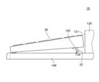
- FIG. 5 is a side view showing the configuration of the main parts of the display device 10 according to this embodiment.
- the display device 10 shown in this figure is the same as the display device 10 according to the first embodiment except for the configuration of the positioning portion of the first input device 20 .
- the positioning portion of the first input device 20 has a concave portion 143 .
- the concave portion 143 is a groove and has a size into which a part of the lower surface of the first input device 20 is inserted.
- the bottom surface of the first input device 20 has a protrusion 22 .
- the projecting portion 22 is rotatable around the end of the projecting portion 22, for example, and can be in both a state along the bottom surface of the first input device 20 and a state projecting from the bottom surface of the first input device 20. can be done.
- the projection 22 is inserted into the recess 143 while projecting from the lower surface of the first input device 20 .
- the orientation of the recessed portion 143 is appropriately determined according to the orientation of the projecting portion 22 .
- recess 143 is substantially parallel to surface 121 .
- the length of the concave portion 143 in the width direction of the display 110 that is, the lateral direction of the user of the display device 10 is appropriately determined according to the position of the projecting portion 22 .
- the recess 143 may be provided only in a part of the pedestal 140 in the lateral direction of the user.
- the recessed part 143 may be provided in the whole base 140 in the left-right direction of the user. However, in this case, the recess 143 does not have to reach the side surface of the base 140 .
- the position of the first input device 20 on the pedestal 140 is also easily determined according to this embodiment.
- FIG. 7 is a side view showing the configuration of the main parts of the display device 10 according to this embodiment.
- the display device 10 shown in this figure is the same as the display device 10 according to the first embodiment, except for the configuration of the positioning portion of the first input device 20 .
- the positioning portion of the first input device 20 has a projecting portion 144 .
- the first input device 20 is positioned by contacting the protrusion 144 or the surface 121 of the housing 120 .
- the housing 120 extends upward from the pedestal 140 and serves as a pillar supporting the display 110 .
- the distance between the surface 121 side of the housing 120 and the surface 121 in the projecting portion 144 is wider than the width of the first input device 20 .
- the first input device 20 is arranged between the protrusion 144 and the surface 121 . This determines the position of the first input device 20 on the base 140 .
- the distance between the protrusion 144 and the surface 121 may be narrower than the width of the first input device 20 .
- the position of the first input device 20 is determined by the contact of the lower surface of the first input device 20 with the upper surface of the projecting portion 144 .
- a high-friction portion may be provided on a portion of the upper surface of the base 140 instead of the protruding portion 144 .
- the high-friction portion is a region having a higher coefficient of friction than other portions of the top surface of the pedestal 140 .
- the top surface of the high-friction portion may be flush with the top surface of the rest of the pedestal 140 .
- the projecting portion 144 may be provided on the entire base 140 in the lateral direction of the user. Further, as shown in the perspective view of FIG. 9 , the perspective view of the projecting portion 144 may be provided only on a part of the base 140 .
- FIG. 10 is a diagram showing the arrangement of the first input device 20 when the user of the display device 10 uses the first input device 20 in this embodiment.
- the first input device 20 has a protrusion 23 near the side opposite to the user's side, for example, within a range of 3 cm from the opposite side.
- the projecting portion 23 is an example of a second projecting portion.
- the user-side side surface of the projecting portion 23 is in contact with the projecting portion 144 provided on the base 140 .
- the projecting portion 144 is an example of a first projecting portion.
- the user-side end of the lower surface of the first input device 20 is in contact with the desk on which the pedestal 140 is placed. In this way, the first input device 20 is positioned by the pedestal 140 even when being used by the user.
- the position of the first input device 20 on the pedestal 140 is also easily determined according to this embodiment.
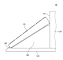
- FIG. 11 is a side view showing the configuration of the main parts of the display device 10 according to this embodiment.
- the display device 10 shown in this figure is the same as the display device 10 according to the first embodiment, except for the configuration of the positioning portion of the first input device 20 .
- the pedestal 140 has a protruding portion 145 .
- the distance between the surface 121 side of the housing 120 and the surface 121 in the projecting portion 145 is narrower than the width of the first input device 20 .
- a support portion 146 is provided between the projection portion 145 and the surface 121 on the upper surface of the pedestal 140 .
- the lower surface of the support portion 146 is in contact with the upper surface of the pedestal 140 , and the upper surface of the support portion 146 is inclined upward from the projecting portion 145 toward the surface 121 .
- the end portion of the support portion 146 on the projecting portion 145 side is lower than the upper end of the projecting portion 145 . It is preferable that the protruding portion 145 be provided on the edge of the upper surface of the pedestal 140 on the user side.
- the first input device 20 is arranged on the upper surface of the support portion 146 . In this state, the end of the first input device 20 on the protruding portion 145 side contacts the side surface of the protruding portion 145 . Thus, the first input device 20 is positioned.
- the supporting portion 146 may be omitted.
- the first input device 20 is sandwiched between the projecting portion 145 and the surface 121 in an oblique state.
- the position of the first input device 20 on the pedestal 140 is also easily determined according to this embodiment. Further, when the protruding portion 145 is provided on the edge of the upper surface of the pedestal 140 on the user side, the depth of the pedestal 140 can be made narrower than the depth of the first input device 20 .
- FIG. 13 is a side view of the display device 10 according to this embodiment.
- the display device 10 shown in this figure is the same as any one of the first to fourth embodiments except for the shape of the top surface of the housing 120 .
- the upper surface of the housing 120 has a first inclined portion 122 .
- the first inclined portion 122 is connected to the side surface of the housing 120 opposite to the display 110 in the thickness direction of the housing 120, that is, the horizontal direction in FIG. Furthermore, the first sloped portion 122 slopes downward as it moves away from the display 110 .
- the first inclined portion 122 occupies 50% or more of the upper surface of the housing 120 in the thickness direction of the housing 120 .
- the portion of the upper surface of the housing 120 other than the first inclined portion 122 is a second inclined portion 124 .
- the second inclined portion 124 is connected to the surface 121 of the housing 120 .
- the second inclined portion 124 is inclined upward with increasing distance from the display 110 .
- the first inclined portion 122 occupies 50% or more, preferably 60% or more of the upper surface of the housing 120 .
- the boundary between the first inclined portion 122 and the second inclined portion 124 is preferably gentle.
- the first inclined portion 122 on the upper surface of the housing 120, it is not possible to place an object, such as a PET bottle containing a beverage, on the upper surface of the housing 120. As a result, it is possible to prevent electronic components inside housing 120 from malfunctioning due to objects placed on the upper surface of housing 120 .
- the pedestal 140 of the display device 10 has a positioning portion for positioning the first input device 20 . Therefore, the position of the first input device 20 is easily fixed on the base 140 .
- FIG. 14 is a perspective view of the display device 10 according to this embodiment.
- the display device 10 shown in this figure is the same as any of the first to fifth embodiments except for the following points.
- the wireless relay device 130 is fixed to the side surface of the housing 120 opposite to the surface 121 .
- the wireless relay device 130 is, for example, a wireless access point, a wireless LAN (Local Area Network) router, a wireless relay, a HUB, a router, or a separator, and communicates with a wireless terminal according to a communication standard such as WiFi (registered trademark).
- the wireless terminal used here may be, for example, a smart phone or a tablet terminal.
- the wireless terminal may be a fixed type terminal having a wireless communication function. Examples of such terminals include notebook personal computers, desktop personal computers, printers, storages, displays such as televisions, smart speakers, audio equipment, and household appliances such as refrigerators.
- the wireless relay device 130 then connects this wireless terminal to a wired line (eg, LAN line) or a high-speed wireless communication line (eg, LTE (Long Term Evolution) or local 5G line).
- a wired line eg, LAN line
- the side surface of the housing 120 that faces neither the display 110 nor the wireless relay device 130 has a concave portion 126 .
- the recess 126 is provided for holding the second input device 30, as shown in FIG.
- the second input device 30 is a handy scanner, and the code information reading portion is wider than the other portions. Then, the reading portion of the second input device 30 is fitted into the concave portion 126 .
- the display device 10 may have other structures for holding the second input device 30, such as hooks and magnets, instead of the recess 126.
- the display device 10 may have only one of the wireless relay device 130 and the recess 126 .
- the position of the first input device 20 on the pedestal 140 is also easily determined according to this embodiment. Also, the housing 120 can hold the second input device 30 .
- a display a support member that supports the display; with The support member has a pedestal, The display device, wherein the pedestal has a positioning portion for positioning the first input device on its upper surface. 2. In the display device described in 1 above, The display device, wherein the positioning portion has a recess provided on the upper surface. 3. 2. In the display device described in 2 above, The display device, wherein the recess is larger than the first input device when viewed from above. 4. 2. In the display device described in 2 above, The first input device has a protrusion, The display device, wherein the recess positions the first input device by receiving the protrusion. 5.
- the display device wherein the positioning portion has a non-slip portion having a higher coefficient of friction than the upper surface of the base. 6. In the display device described in 1 above, The display device, wherein the positioning portion has a first projecting portion. 7. 6. In the display device according to 6 above, The support member has a strut extending upward from the pedestal, A display device, wherein the first input device is arranged between the first protrusion and the support. 8. 8.
- the first input device is a keyboard; the lower surface of the keyboard has a second protrusion, The display device, wherein a side surface of the first protrusion and a side surface of the second protrusion are arranged to contact each other when the keyboard is used.
- a control unit that controls the display a housing that accommodates the control unit; with At least part of the back surface of the display faces the side surface of the housing,
- the upper surface of the housing has an inclined portion that is inclined in the thickness direction of the display, The display device, wherein the inclined portion accounts for 50% or more of the upper surface.
- a control unit that controls the display a housing that accommodates the control unit; with A display device in which a side surface of the housing has a concave portion for holding a second input device.
Landscapes
- Engineering & Computer Science (AREA)
- Theoretical Computer Science (AREA)
- General Engineering & Computer Science (AREA)
- Human Computer Interaction (AREA)
- Physics & Mathematics (AREA)
- General Physics & Mathematics (AREA)
- Computer Hardware Design (AREA)
- Microelectronics & Electronic Packaging (AREA)
- Devices For Indicating Variable Information By Combining Individual Elements (AREA)
Priority Applications (2)
| Application Number | Priority Date | Filing Date | Title |
|---|---|---|---|
| US18/692,935 US20240385646A1 (en) | 2021-09-30 | 2022-09-02 | Display apparatus |
| JP2023550491A JP7655582B2 (ja) | 2021-09-30 | 2022-09-02 | 表示装置 |
Applications Claiming Priority (2)
| Application Number | Priority Date | Filing Date | Title |
|---|---|---|---|
| JP2021160789 | 2021-09-30 | ||
| JP2021-160789 | 2021-09-30 |
Publications (1)
| Publication Number | Publication Date |
|---|---|
| WO2023053844A1 true WO2023053844A1 (ja) | 2023-04-06 |
Family
ID=85780638
Family Applications (1)
| Application Number | Title | Priority Date | Filing Date |
|---|---|---|---|
| PCT/JP2022/033086 Ceased WO2023053844A1 (ja) | 2021-09-30 | 2022-09-02 | 表示装置 |
Country Status (3)
| Country | Link |
|---|---|
| US (1) | US20240385646A1 (https=) |
| JP (1) | JP7655582B2 (https=) |
| WO (1) | WO2023053844A1 (https=) |
Citations (4)
| Publication number | Priority date | Publication date | Assignee | Title |
|---|---|---|---|---|
| JPH08328694A (ja) * | 1995-05-31 | 1996-12-13 | Toyo Joho Syst:Kk | スタンドコンピュータ |
| JP2002073213A (ja) * | 2000-09-05 | 2002-03-12 | Sony Corp | 情報処理装置 |
| JP2005316867A (ja) * | 2004-04-30 | 2005-11-10 | Casio Comput Co Ltd | 情報処理装置 |
| US20170009934A1 (en) * | 2014-02-28 | 2017-01-12 | Bakkerelkhuizen Innovations B.V. | Stand for a Portable Device with a Graphic User Interface Display |
-
2022
- 2022-09-02 JP JP2023550491A patent/JP7655582B2/ja active Active
- 2022-09-02 US US18/692,935 patent/US20240385646A1/en active Pending
- 2022-09-02 WO PCT/JP2022/033086 patent/WO2023053844A1/ja not_active Ceased
Patent Citations (4)
| Publication number | Priority date | Publication date | Assignee | Title |
|---|---|---|---|---|
| JPH08328694A (ja) * | 1995-05-31 | 1996-12-13 | Toyo Joho Syst:Kk | スタンドコンピュータ |
| JP2002073213A (ja) * | 2000-09-05 | 2002-03-12 | Sony Corp | 情報処理装置 |
| JP2005316867A (ja) * | 2004-04-30 | 2005-11-10 | Casio Comput Co Ltd | 情報処理装置 |
| US20170009934A1 (en) * | 2014-02-28 | 2017-01-12 | Bakkerelkhuizen Innovations B.V. | Stand for a Portable Device with a Graphic User Interface Display |
Also Published As
| Publication number | Publication date |
|---|---|
| US20240385646A1 (en) | 2024-11-21 |
| JP7655582B2 (ja) | 2025-04-02 |
| JPWO2023053844A1 (https=) | 2023-04-06 |
Similar Documents
| Publication | Publication Date | Title |
|---|---|---|
| US10606311B2 (en) | Electronic device | |
| US8665589B2 (en) | Peripheral input device | |
| US6522530B2 (en) | Computer system having a monitor movably coupled to a main body | |
| JP2021064382A (ja) | 電子機器 | |
| KR20190065416A (ko) | 모듈형 컴퓨팅 시스템 | |
| US20040113031A1 (en) | Monitor | |
| JP2014183113A (ja) | 電子機器用のスタンド | |
| US6778385B2 (en) | Portable computer with removable bottom component housing | |
| US9042091B2 (en) | Portable electronic device with hinge structure | |
| JP3233129U (ja) | マルチレベル電子製品補助使用ラック | |
| CN103179826A (zh) | 电子装置 | |
| JP7372400B2 (ja) | 収納庫用仕切り部材及び収納庫 | |
| WO2023053844A1 (ja) | 表示装置 | |
| US20120169191A1 (en) | Server having retractable foot pad | |
| JP4846345B2 (ja) | ワゴン | |
| JP2011107991A (ja) | 情報処理装置及び支持台 | |
| KR102169936B1 (ko) | 사용자 단말기 거치 겸용 서류함 | |
| KR20190099549A (ko) | 스마트폰 거치대 | |
| CN108664086B (zh) | 一种电子设备 | |
| CN216623099U (zh) | 一种便携式计算机的支脚 | |
| TWI545466B (zh) | 具有輔助支撐結構的鍵盤 | |
| TWM491912U (zh) | 具活動式支撐結構的電子裝置 | |
| JP2017092495A (ja) | 電子機器用のスタンド | |
| JP7372413B2 (ja) | 収納庫用仕切り部材及び収納庫 | |
| KR200500056Y1 (ko) | 테이블용 키오스크 고정장치 |
Legal Events
| Date | Code | Title | Description |
|---|---|---|---|
| 121 | Ep: the epo has been informed by wipo that ep was designated in this application |
Ref document number: 22875716 Country of ref document: EP Kind code of ref document: A1 |
|
| WWE | Wipo information: entry into national phase |
Ref document number: 2023550491 Country of ref document: JP |
|
| WWE | Wipo information: entry into national phase |
Ref document number: 18692935 Country of ref document: US |
|
| NENP | Non-entry into the national phase |
Ref country code: DE |
|
| 122 | Ep: pct application non-entry in european phase |
Ref document number: 22875716 Country of ref document: EP Kind code of ref document: A1 |