WO2023053812A1 - 超音波センサ - Google Patents
超音波センサ Download PDFInfo
- Publication number
- WO2023053812A1 WO2023053812A1 PCT/JP2022/032398 JP2022032398W WO2023053812A1 WO 2023053812 A1 WO2023053812 A1 WO 2023053812A1 JP 2022032398 W JP2022032398 W JP 2022032398W WO 2023053812 A1 WO2023053812 A1 WO 2023053812A1
- Authority
- WO
- WIPO (PCT)
- Prior art keywords
- elastic member
- vibrating body
- ultrasonic sensor
- housing
- elastic
- Prior art date
- Legal status (The legal status is an assumption and is not a legal conclusion. Google has not performed a legal analysis and makes no representation as to the accuracy of the status listed.)
- Ceased
Links
Images







Classifications
-
- G—PHYSICS
- G01—MEASURING; TESTING
- G01S—RADIO DIRECTION-FINDING; RADIO NAVIGATION; DETERMINING DISTANCE OR VELOCITY BY USE OF RADIO WAVES; LOCATING OR PRESENCE-DETECTING BY USE OF THE REFLECTION OR RERADIATION OF RADIO WAVES; ANALOGOUS ARRANGEMENTS USING OTHER WAVES
- G01S7/00—Details of systems according to groups G01S13/00, G01S15/00, G01S17/00
- G01S7/52—Details of systems according to groups G01S13/00, G01S15/00, G01S17/00 of systems according to group G01S15/00
- G01S7/521—Constructional features
-
- B—PERFORMING OPERATIONS; TRANSPORTING
- B06—GENERATING OR TRANSMITTING MECHANICAL VIBRATIONS IN GENERAL
- B06B—METHODS OR APPARATUS FOR GENERATING OR TRANSMITTING MECHANICAL VIBRATIONS OF INFRASONIC, SONIC, OR ULTRASONIC FREQUENCY, e.g. FOR PERFORMING MECHANICAL WORK IN GENERAL
- B06B1/00—Methods or apparatus for generating mechanical vibrations of infrasonic, sonic, or ultrasonic frequency
- B06B1/02—Methods or apparatus for generating mechanical vibrations of infrasonic, sonic, or ultrasonic frequency making use of electrical energy
- B06B1/06—Methods or apparatus for generating mechanical vibrations of infrasonic, sonic, or ultrasonic frequency making use of electrical energy operating with piezoelectric effect or with electrostriction
- B06B1/0644—Methods or apparatus for generating mechanical vibrations of infrasonic, sonic, or ultrasonic frequency making use of electrical energy operating with piezoelectric effect or with electrostriction using a single piezoelectric element
-
- G—PHYSICS
- G01—MEASURING; TESTING
- G01S—RADIO DIRECTION-FINDING; RADIO NAVIGATION; DETERMINING DISTANCE OR VELOCITY BY USE OF RADIO WAVES; LOCATING OR PRESENCE-DETECTING BY USE OF THE REFLECTION OR RERADIATION OF RADIO WAVES; ANALOGOUS ARRANGEMENTS USING OTHER WAVES
- G01S15/00—Systems using the reflection or reradiation of acoustic waves, e.g. sonar systems
- G01S15/88—Sonar systems specially adapted for specific applications
- G01S15/93—Sonar systems specially adapted for specific applications for anti-collision purposes
- G01S15/931—Sonar systems specially adapted for specific applications for anti-collision purposes of land vehicles
-
- G—PHYSICS
- G10—MUSICAL INSTRUMENTS; ACOUSTICS
- G10K—SOUND-PRODUCING DEVICES; METHODS OR DEVICES FOR PROTECTING AGAINST, OR FOR DAMPING, NOISE OR OTHER ACOUSTIC WAVES IN GENERAL; ACOUSTICS NOT OTHERWISE PROVIDED FOR
- G10K9/00—Devices in which sound is produced by vibrating a diaphragm or analogous element, e.g. fog horns, vehicle hooters or buzzers
- G10K9/12—Devices in which sound is produced by vibrating a diaphragm or analogous element, e.g. fog horns, vehicle hooters or buzzers electrically operated
- G10K9/122—Devices in which sound is produced by vibrating a diaphragm or analogous element, e.g. fog horns, vehicle hooters or buzzers electrically operated using piezoelectric driving means
-
- G—PHYSICS
- G10—MUSICAL INSTRUMENTS; ACOUSTICS
- G10K—SOUND-PRODUCING DEVICES; METHODS OR DEVICES FOR PROTECTING AGAINST, OR FOR DAMPING, NOISE OR OTHER ACOUSTIC WAVES IN GENERAL; ACOUSTICS NOT OTHERWISE PROVIDED FOR
- G10K9/00—Devices in which sound is produced by vibrating a diaphragm or analogous element, e.g. fog horns, vehicle hooters or buzzers
- G10K9/18—Details, e.g. bulbs, pumps, pistons, switches or casings
- G10K9/22—Mountings; Casings
-
- H—ELECTRICITY
- H04—ELECTRIC COMMUNICATION TECHNIQUE
- H04R—LOUDSPEAKERS, MICROPHONES, GRAMOPHONE PICK-UPS OR LIKE ACOUSTIC ELECTROMECHANICAL TRANSDUCERS; ELECTRIC HEARING AIDS; PUBLIC ADDRESS SYSTEMS
- H04R17/00—Piezoelectric transducers; Electrostrictive transducers
-
- B—PERFORMING OPERATIONS; TRANSPORTING
- B06—GENERATING OR TRANSMITTING MECHANICAL VIBRATIONS IN GENERAL
- B06B—METHODS OR APPARATUS FOR GENERATING OR TRANSMITTING MECHANICAL VIBRATIONS OF INFRASONIC, SONIC, OR ULTRASONIC FREQUENCY, e.g. FOR PERFORMING MECHANICAL WORK IN GENERAL
- B06B1/00—Methods or apparatus for generating mechanical vibrations of infrasonic, sonic, or ultrasonic frequency
- B06B1/02—Methods or apparatus for generating mechanical vibrations of infrasonic, sonic, or ultrasonic frequency making use of electrical energy
- B06B1/06—Methods or apparatus for generating mechanical vibrations of infrasonic, sonic, or ultrasonic frequency making use of electrical energy operating with piezoelectric effect or with electrostriction
- B06B1/0644—Methods or apparatus for generating mechanical vibrations of infrasonic, sonic, or ultrasonic frequency making use of electrical energy operating with piezoelectric effect or with electrostriction using a single piezoelectric element
- B06B1/0648—Methods or apparatus for generating mechanical vibrations of infrasonic, sonic, or ultrasonic frequency making use of electrical energy operating with piezoelectric effect or with electrostriction using a single piezoelectric element of rectangular shape
-
- B—PERFORMING OPERATIONS; TRANSPORTING
- B06—GENERATING OR TRANSMITTING MECHANICAL VIBRATIONS IN GENERAL
- B06B—METHODS OR APPARATUS FOR GENERATING OR TRANSMITTING MECHANICAL VIBRATIONS OF INFRASONIC, SONIC, OR ULTRASONIC FREQUENCY, e.g. FOR PERFORMING MECHANICAL WORK IN GENERAL
- B06B1/00—Methods or apparatus for generating mechanical vibrations of infrasonic, sonic, or ultrasonic frequency
- B06B1/02—Methods or apparatus for generating mechanical vibrations of infrasonic, sonic, or ultrasonic frequency making use of electrical energy
- B06B1/06—Methods or apparatus for generating mechanical vibrations of infrasonic, sonic, or ultrasonic frequency making use of electrical energy operating with piezoelectric effect or with electrostriction
- B06B1/0644—Methods or apparatus for generating mechanical vibrations of infrasonic, sonic, or ultrasonic frequency making use of electrical energy operating with piezoelectric effect or with electrostriction using a single piezoelectric element
- B06B1/0651—Methods or apparatus for generating mechanical vibrations of infrasonic, sonic, or ultrasonic frequency making use of electrical energy operating with piezoelectric effect or with electrostriction using a single piezoelectric element of circular shape
-
- B—PERFORMING OPERATIONS; TRANSPORTING
- B06—GENERATING OR TRANSMITTING MECHANICAL VIBRATIONS IN GENERAL
- B06B—METHODS OR APPARATUS FOR GENERATING OR TRANSMITTING MECHANICAL VIBRATIONS OF INFRASONIC, SONIC, OR ULTRASONIC FREQUENCY, e.g. FOR PERFORMING MECHANICAL WORK IN GENERAL
- B06B1/00—Methods or apparatus for generating mechanical vibrations of infrasonic, sonic, or ultrasonic frequency
- B06B1/02—Methods or apparatus for generating mechanical vibrations of infrasonic, sonic, or ultrasonic frequency making use of electrical energy
- B06B1/06—Methods or apparatus for generating mechanical vibrations of infrasonic, sonic, or ultrasonic frequency making use of electrical energy operating with piezoelectric effect or with electrostriction
- B06B1/0644—Methods or apparatus for generating mechanical vibrations of infrasonic, sonic, or ultrasonic frequency making use of electrical energy operating with piezoelectric effect or with electrostriction using a single piezoelectric element
- B06B1/0655—Methods or apparatus for generating mechanical vibrations of infrasonic, sonic, or ultrasonic frequency making use of electrical energy operating with piezoelectric effect or with electrostriction using a single piezoelectric element of cylindrical shape
-
- G—PHYSICS
- G01—MEASURING; TESTING
- G01S—RADIO DIRECTION-FINDING; RADIO NAVIGATION; DETERMINING DISTANCE OR VELOCITY BY USE OF RADIO WAVES; LOCATING OR PRESENCE-DETECTING BY USE OF THE REFLECTION OR RERADIATION OF RADIO WAVES; ANALOGOUS ARRANGEMENTS USING OTHER WAVES
- G01S15/00—Systems using the reflection or reradiation of acoustic waves, e.g. sonar systems
- G01S15/88—Sonar systems specially adapted for specific applications
- G01S15/93—Sonar systems specially adapted for specific applications for anti-collision purposes
- G01S15/931—Sonar systems specially adapted for specific applications for anti-collision purposes of land vehicles
- G01S2015/937—Sonar systems specially adapted for specific applications for anti-collision purposes of land vehicles sensor installation details
- G01S2015/938—Sonar systems specially adapted for specific applications for anti-collision purposes of land vehicles sensor installation details in the bumper area
-
- H—ELECTRICITY
- H10—SEMICONDUCTOR DEVICES; ELECTRIC SOLID-STATE DEVICES NOT OTHERWISE PROVIDED FOR
- H10N—ELECTRIC SOLID-STATE DEVICES NOT OTHERWISE PROVIDED FOR
- H10N30/00—Piezoelectric or electrostrictive devices
- H10N30/80—Constructional details
- H10N30/88—Mounts; Supports; Enclosures; Casings
Definitions
- the present invention relates to ultrasonic sensors.
- An ultrasonic sensor disclosed in Patent Document 1 includes an ultrasonic transducer.
- This ultrasonic transducer includes a cylindrical housing with a bottom, a piezoelectric element fixed to the bottom of the housing, and a base fixed to an opening of the housing via a spacer.
- the spacer consists of an elastic body.
- the housing has a bottom and a barrel.
- the spacer is an elastic body that prevents unwanted vibrations generated in the cylindrical portion due to the vibration of the bottom from being transmitted to the base.
- a cylindrical elastic body is placed over such an ultrasonic transducer, and a foamed elastic body is arranged under the base as an elastic body for suppressing vibration.
- the spacer of Patent Document 1 has a rib shape, and the outer surface of the rib shape is exposed on the outer peripheral surface of the ultrasonic transducer in order to block vibration transmission. Since the shape of this spacer is not symmetrical on the front and back, care must be taken not to confuse the front and back when assembling.
- Patent Document 1 describes that the spacer is made of, for example, silicone rubber.
- the spacer has a large specific gravity and is not sufficiently effective in inhibiting vibration transmission.
- the contact of such a spacer with the housing may change the frequency of unnecessary vibrations, resulting in fluctuations in product characteristics.
- an object of the present invention is to provide an ultrasonic sensor that is easy to assemble and that can suppress unnecessary vibration transmission as much as possible.
- an ultrasonic sensor comprises a vibrating body including a cylindrical portion and a bottom portion closing one end of the cylindrical portion, and a piezoelectric element fixed to the inner surface of the bottom portion of the vibrating body.
- a first housing member forming at least a part of a housing that houses the vibrating body; and a first elastic member sandwiched between the vibrating body and the first housing member.
- the first elastic member has a symmetrical shape and a closed cell structure.
- the first elastic member sandwiched between the vibrating body and the first housing member has a symmetrical shape and a closed cell structure, the assembly work is easy. , it is possible to realize an ultrasonic sensor capable of suppressing unnecessary vibration transmission as much as possible.
- FIG. 1 is a first perspective view of an ultrasonic sensor according to Embodiment 1 of the present invention
- FIG. 1 is an exploded view of an ultrasonic sensor according to Embodiment 1 of the present invention
- FIG. 1 is an exploded view related to a vibrating body included in an ultrasonic sensor according to Embodiment 1 of the present invention
- FIG. 4 is a second perspective view of the ultrasonic sensor in Embodiment 1 based on the present invention
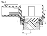
- 5 is a cross-sectional view taken along line VV in FIG. 4
- FIG. 5 is a cross-sectional view taken along line VI-VI in FIG. 4;
- FIG. 6 is a cross-sectional view of the one shown in Figure 5 with the first and second filling members removed;
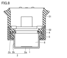
- Figure 7 is a cross-sectional view of the one shown in Figure 6 with the first and second filling members removed;
- 3 is an exploded view of some of the parts shown in FIG. 2, viewed from a different orientation;
- FIG. FIG. 10 is an exploded view of the part group shown in FIG. 9 partially assembled;
- FIG. 2 is a perspective view of a state in which a vibrating body, a second elastic member, and a second housing member included in the ultrasonic sensor according to Embodiment 1 of the present invention are combined;
- 12 is a perspective view of a state in which the first elastic member 4 is combined with the one shown in FIG. 11;
- FIG. 10 is a first explanatory diagram for showing the advantage of the first elastic member having a closed-cell structure
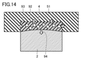
- FIG. 10 is a second explanatory diagram for showing the advantage of the first elastic member having a closed-cell structure
- 4 is a graph showing the magnitude of the reaction force generated in the periphery with respect to the amount of pushing applied to the elastic member.
- FIG. 1 shows an ultrasonic sensor 101 according to this embodiment.
- An exploded view of the ultrasonic sensor 101 is shown in FIG.
- the ultrasonic sensor 101 includes a rear cover 6, a wiring board assembly 7, a first filling member 8, a second filling member 9, wiring 10, a first housing member 51, a first elastic member 4, vibration It includes a body 2 , a second elastic member 5 and a second housing member 52 .
- the first elastic member 4 has a closed cell structure.
- the vibrating body 2 has a cylindrical shape with a bottom. Vibrating body 2 is made of metal, for example.
- the metal referred to here is, for example, aluminum.
- the vibrating body 2 includes a bottom portion 2a, a cylindrical portion 2b, and a flange portion 2c.
- the first housing member 51 and the second housing member 52 are made of resin, for example.
- the material of the first housing member 51 and the material of the second housing member 52 may be of the same type.
- Rear cover 6 may be made of resin, for example.
- the first filling member 8 is made of foamed silicone, for example.
- the second filling member 9 is a silicone member arranged by potting, for example.
- the second elastic member 5 is made of rubber, for example.
- the piezoelectric element 1 is arranged inside the vibrating body 2 .
- the piezoelectric element 1 is attached to the inner surface of the bottom portion 2a via the adhesive sheet 3.
- the adhesive sheet 3 may be a double-sided tape.
- FIG. 4 shows the ultrasonic sensor 101 with the rear cover 6 facing upward.
- the posture shown in FIG. 4 corresponds to a state inverted upside down compared to the posture shown in FIG.
- FIG. 5 shows a cross-sectional view taken along line VV in FIG.
- FIG. 6 shows a cross-sectional view taken along line VI-VI in FIG. 5 and 6, the rear cover 6, the wiring board assembly 7, the wiring 10, the adhesive sheet 3, etc. are omitted from illustration.
- the first elastic member 4 is sandwiched between the vibrating body 2 and the first housing member 51 .
- a first filling member 8 is arranged so as to be in contact with the piezoelectric element 1 and the bottom portion 2a.
- a second filling member 9 is arranged to cover the first filling member 8 .
- a part of the second filling member 9 protrudes outside from the internal space of the vibrating body 2 .
- the first elastic member 4 is annular. That is, the first elastic member 4 has an opening.
- the second filling member 9 penetrates through the opening of the first elastic member 4 .
- FIG. 7 shows a state in which the first filling member 8 and the second filling member 9 are removed from the one shown in FIG.
- FIG. 8 shows a state in which the first filling member 8 and the second filling member 9 are removed from the one shown in FIG.
- FIG. 9 shows an exploded view of some of the parts shown in Fig. 2, viewed from different directions.
- the first housing member 51, the first elastic member 4, the vibrating body 2, the second elastic member 5, and the second housing member 52 are displayed.
- FIG. 10 shows a state in which these are assembled halfway.
- FIG. 10 also shows the piezoelectric element 1 attached to the inner surface of the vibrating body 2 .
- FIG. 11 shows a state in which the vibrating body 2, the second elastic member 5, and the second housing member 52 are combined.
- FIG. 12 shows a state in which the first elastic member 4 is further combined with the one shown in FIG.
- the configuration of the ultrasonic sensor 101 can be expressed, for example, as follows.
- the ultrasonic sensor 101 includes a vibrating body 2 including a cylindrical portion 2b and a bottom portion 2a closing one end of the cylindrical portion 2b, a piezoelectric element 1 fixed to the inner surface of the bottom portion 2a of the vibrating body 2, and the vibrating body 2.
- a first housing member 51 forming at least a part of a housing to be accommodated, and a first elastic member 4 sandwiched between the vibrating body 2 and the first housing member 51 are provided.
- the first elastic member 4 has a symmetrical shape and a closed cell structure.
- the ultrasonic sensor 101 includes the first elastic member 4 sandwiched between the vibrating body 2 and the first housing member 51, and the first elastic member 4 has a closed cell structure. , the vibration transmission from the vibrating body 2 to the first housing member 51 can be more effectively inhibited. That is, unnecessary vibration transmission can be suppressed as much as possible.
- the first elastic member 4 since the first elastic member 4 has a symmetrical shape, it is not necessary to distinguish between the front and back during the assembly work. Therefore, assembly work becomes easy.
- FIG. 13 and 14 the structure is schematically represented for convenience of explanation.
- the first elastic member 4 is interposed between the first housing member 51 and the vibrating body 2 , and the vibration of the vibrating body 2 causes the upper surface of the vibrating body 2 to move in the direction of arrow 91 .
- the lower surface of the first elastic member 4 is pushed and displaced so as to enter the inside of the first elastic member 4, acting in the direction of reducing the volume of the first elastic member 4.
- FIG. 13 the structure is schematically represented for convenience of explanation.
- the first elastic member 4 is made of rubber, it has a constant Poisson's ratio. Therefore, if the lower surface of the first elastic member 4 is pushed in, the first elastic member 4 will have an amount corresponding to the pushed volume. The top and outer surfaces of the try to push out from the original surface. As a result, the first housing member 51 is pushed and displaced. Vibration is transmitted to the first housing member 51 by repeating such displacement.
- each closed cell inside the first elastic member 4 can be compressed and contracted. Therefore, some portion of the imposed volume change is absorbed by the closed cells.
- the force that tends to push the first elastic member 4 outward from the original surface at the upper surface and the outer peripheral surface is reduced. Therefore, the amount by which the first housing member 51 is pushed and displaced is also reduced. As a result, the degree of transmission of vibration to the first housing member 51 can be reduced.
- Fig. 15 shows a graph of the magnitude of the reaction force generated around the elastic member against the amount of pushing.
- a curve 71 indicates the case where a rubber having a hardness of 50 is used as the elastic member.
- a curve 72 shows the case where a rubber having a hardness of 30 is used as the elastic member.
- a curve 73 shows the case where a sponge having a hardness of 30 is used as the elastic member.
- Curve 74 shows the case of using a sponge with a hardness of 20 as the elastic member.
- a curve 75 shows the case where a sponge having a hardness of 15 is used as the elastic member.
- the hardness of the rubber was measured with a type A durometer (Asker A type) in accordance with JIS K6253-3.
- the hardness of the sponge was measured with a type E durometer (Asker C type) conforming to JIS K6253-3.
- JIS K6253-3 in the JIS standard corresponds to ISO 48-4 in the ISO standard.
- Curves 71 and 72 correspond to the case with a member without a closed cell structure and curves 73, 74 and 75 correspond to the case with a member with a closed cell structure.
- curves 73, 74, and 75 tend to keep the reaction force smaller than curves 71 and 72 even when the pushing amount is the same. Reducing the reaction force makes it easier to suppress the transmission of unnecessary vibrations.
- a member with closed cells does not easily pass water and the like compared to a member with continuous cells, so it has a high waterproof performance. In the case of continuous air bubbles, it is difficult to pick up by vacuum suction because air passes through.
- first filling member 8 and the second filling member 9 when filling a liquid material to form them, if the first elastic member 4 is a member provided with closed cells, the liquid material is used. This is preferable because it is possible to avoid intrusion into the first elastic member 4 .
- the inventor observed the reverberation when the Asker hardness, which is the hardness of the sponge, was 10 and 30 respectively. That is, the inventor drove the piezoelectric element 1 for a certain period of time to vibrate the vibrating body 2, and then observed the vibration remaining when the piezoelectric element 1 was stopped, that is, the reverberation. As a result, it was confirmed that reverberation was suppressed to be smaller when Asker hardness was 10 than when Asker hardness was 30.
- the inventor conducted an experiment to measure the reverberation time at a low temperature for each of the first elastic members 4 having hardnesses of 10, 15, and 20. Even though the elastic member is hardened at low temperatures, the reaction force can be kept small, indicating that the vibration transmission inhibition function is excellent.
- the vibrating body 2 has the flange portion 2c, and the first elastic member 4 is in contact with the flange portion 2c.
- the first elastic member 4 can stably support the vibrating body 2 .
- the first elastic member 4 can reduce the degree to which unnecessary vibration is transmitted from the vibrating body 2 to other members.
- the first elastic member 4 is preferably an annular member having a constant thickness. By adopting this configuration, it becomes easy to support the vibrating body 2 evenly.
- the first elastic member 4 may be formed, for example, by punching a plate material having a certain thickness.
- the first elastic member 4 is preferably made of at least one material selected from the group consisting of silicone, modified silicone and urethane. By adopting this configuration, it is possible to satisfactorily suppress unnecessary vibration transmission.
- the first elastic member 4 is formed by subjecting a material that satisfies this condition to a foaming process that can form a closed-cell structure.
Landscapes
- Engineering & Computer Science (AREA)
- Physics & Mathematics (AREA)
- Radar, Positioning & Navigation (AREA)
- Remote Sensing (AREA)
- Acoustics & Sound (AREA)
- Computer Networks & Wireless Communication (AREA)
- General Physics & Mathematics (AREA)
- Mechanical Engineering (AREA)
- Multimedia (AREA)
- Signal Processing (AREA)
- Transducers For Ultrasonic Waves (AREA)
- Measurement Of Velocity Or Position Using Acoustic Or Ultrasonic Waves (AREA)
Priority Applications (4)
| Application Number | Priority Date | Filing Date | Title |
|---|---|---|---|
| EP22875684.7A EP4412248A4 (en) | 2021-09-29 | 2022-08-29 | ULTRASONIC SENSOR |
| CN202280064105.6A CN117999800A (zh) | 2021-09-29 | 2022-08-29 | 超声波传感器 |
| JP2023550472A JP7563622B2 (ja) | 2021-09-29 | 2022-08-29 | 超音波センサ |
| US18/596,866 US20240210546A1 (en) | 2021-09-29 | 2024-03-06 | Ultrasonic sensor |
Applications Claiming Priority (2)
| Application Number | Priority Date | Filing Date | Title |
|---|---|---|---|
| JP2021-158580 | 2021-09-29 | ||
| JP2021158580 | 2021-09-29 |
Related Child Applications (1)
| Application Number | Title | Priority Date | Filing Date |
|---|---|---|---|
| US18/596,866 Continuation US20240210546A1 (en) | 2021-09-29 | 2024-03-06 | Ultrasonic sensor |
Publications (1)
| Publication Number | Publication Date |
|---|---|
| WO2023053812A1 true WO2023053812A1 (ja) | 2023-04-06 |
Family
ID=85780640
Family Applications (1)
| Application Number | Title | Priority Date | Filing Date |
|---|---|---|---|
| PCT/JP2022/032398 Ceased WO2023053812A1 (ja) | 2021-09-29 | 2022-08-29 | 超音波センサ |
Country Status (5)
| Country | Link |
|---|---|
| US (1) | US20240210546A1 (https=) |
| EP (1) | EP4412248A4 (https=) |
| JP (1) | JP7563622B2 (https=) |
| CN (1) | CN117999800A (https=) |
| WO (1) | WO2023053812A1 (https=) |
Families Citing this family (1)
| Publication number | Priority date | Publication date | Assignee | Title |
|---|---|---|---|---|
| DE102021118641A1 (de) * | 2021-07-20 | 2023-01-26 | Valeo Schalter Und Sensoren Gmbh | Entkopplungselement für einen ultraschallsensor |
Citations (6)
| Publication number | Priority date | Publication date | Assignee | Title |
|---|---|---|---|---|
| JPS59119697U (ja) * | 1983-02-01 | 1984-08-13 | 日本特殊陶業株式会社 | 超音波マイクロフオン |
| JP2006180317A (ja) * | 2004-12-24 | 2006-07-06 | Matsushita Electric Ind Co Ltd | 超音波送受波器およびそれを用いた流体の流れ計測装置 |
| DE102006028213A1 (de) * | 2006-06-14 | 2007-12-20 | Valeo Schalter Und Sensoren Gmbh | Ultraschallsensor mit Entkopplungselement |
| JP4438667B2 (ja) | 2005-03-29 | 2010-03-24 | 株式会社デンソー | 超音波センサ及び超音波振動子 |
| JP2013141176A (ja) * | 2012-01-06 | 2013-07-18 | Nippon Ceramic Co Ltd | 超音波送受波器 |
| WO2021044764A1 (ja) * | 2019-09-02 | 2021-03-11 | 株式会社村田製作所 | 超音波センサ装置 |
Family Cites Families (3)
| Publication number | Priority date | Publication date | Assignee | Title |
|---|---|---|---|---|
| DE3939387A1 (de) * | 1989-11-29 | 1991-06-06 | Swf Auto Electric Gmbh | Abstandswarnanlage, insbesondere fuer kraftfahrzeuge |
| DE102014115333A1 (de) * | 2014-10-21 | 2016-04-21 | Valeo Schalter Und Sensoren Gmbh | Ultraschallsensor für ein Kraftfahrzeug, Anordnung, Kraftfahrzeug sowie Herstellungsverfahren |
| JP6870594B2 (ja) * | 2017-11-28 | 2021-05-12 | 株式会社デンソー | 超音波センサ |
-
2022
- 2022-08-29 JP JP2023550472A patent/JP7563622B2/ja active Active
- 2022-08-29 EP EP22875684.7A patent/EP4412248A4/en active Pending
- 2022-08-29 CN CN202280064105.6A patent/CN117999800A/zh active Pending
- 2022-08-29 WO PCT/JP2022/032398 patent/WO2023053812A1/ja not_active Ceased
-
2024
- 2024-03-06 US US18/596,866 patent/US20240210546A1/en active Pending
Patent Citations (6)
| Publication number | Priority date | Publication date | Assignee | Title |
|---|---|---|---|---|
| JPS59119697U (ja) * | 1983-02-01 | 1984-08-13 | 日本特殊陶業株式会社 | 超音波マイクロフオン |
| JP2006180317A (ja) * | 2004-12-24 | 2006-07-06 | Matsushita Electric Ind Co Ltd | 超音波送受波器およびそれを用いた流体の流れ計測装置 |
| JP4438667B2 (ja) | 2005-03-29 | 2010-03-24 | 株式会社デンソー | 超音波センサ及び超音波振動子 |
| DE102006028213A1 (de) * | 2006-06-14 | 2007-12-20 | Valeo Schalter Und Sensoren Gmbh | Ultraschallsensor mit Entkopplungselement |
| JP2013141176A (ja) * | 2012-01-06 | 2013-07-18 | Nippon Ceramic Co Ltd | 超音波送受波器 |
| WO2021044764A1 (ja) * | 2019-09-02 | 2021-03-11 | 株式会社村田製作所 | 超音波センサ装置 |
Non-Patent Citations (1)
| Title |
|---|
| See also references of EP4412248A4 |
Also Published As
| Publication number | Publication date |
|---|---|
| US20240210546A1 (en) | 2024-06-27 |
| JP7563622B2 (ja) | 2024-10-08 |
| EP4412248A1 (en) | 2024-08-07 |
| CN117999800A (zh) | 2024-05-07 |
| EP4412248A4 (en) | 2025-10-15 |
| JPWO2023053812A1 (https=) | 2023-04-06 |
Similar Documents
| Publication | Publication Date | Title |
|---|---|---|
| US9993056B2 (en) | Waterproof case for electronic device | |
| US9433271B2 (en) | Protective cover with an acoustic isolation mechanism | |
| US20170006382A1 (en) | Graphene composite acoustic diaphragm | |
| US11977683B2 (en) | Modular systems configured to provide localized haptic feedback using inertial actuators | |
| JP2017152945A (ja) | 電子機器 | |
| WO2023053812A1 (ja) | 超音波センサ | |
| JP2006129117A (ja) | 電子機器の表示部構造及びこれを備えた電子機器 | |
| JPWO2012060042A1 (ja) | 電子機器 | |
| CN109963659B (zh) | 振动促动器安装结构、具有该振动促动器安装结构的电子设备以及该振动促动器安装结构的制造方法 | |
| JPWO2012060046A1 (ja) | 電子機器 | |
| JP6627846B2 (ja) | センサーユニット及び楽器 | |
| EP3005666B1 (en) | Waterproof acoustic isolation mechanism with membrane | |
| CN116210232B (zh) | 传感装置 | |
| CN113115189B (zh) | 扬声器盒和听力设备 | |
| US20040246453A1 (en) | Laser unit | |
| EP3652961B1 (en) | Portable loudspeaker | |
| JP2019106581A (ja) | 電子機器 | |
| TWI834214B (zh) | 感測裝置 | |
| JP6612562B2 (ja) | 音響装置 | |
| JP2003143678A (ja) | マイクロフォン用緩衝材及びマイクロフォン保持装置 | |
| JP5386440B2 (ja) | パネル装置 | |
| JP2018178675A (ja) | 蓋スピーカー | |
| JPH09247786A (ja) | 水中送受波器 | |
| JPH01171400A (ja) | 圧電発音体 | |
| JPS60134600A (ja) | 圧電発音装置 |
Legal Events
| Date | Code | Title | Description |
|---|---|---|---|
| 121 | Ep: the epo has been informed by wipo that ep was designated in this application |
Ref document number: 22875684 Country of ref document: EP Kind code of ref document: A1 |
|
| WWE | Wipo information: entry into national phase |
Ref document number: 2023550472 Country of ref document: JP |
|
| WWE | Wipo information: entry into national phase |
Ref document number: 202280064105.6 Country of ref document: CN |
|
| NENP | Non-entry into the national phase |
Ref country code: DE |
|
| ENP | Entry into the national phase |
Ref document number: 2022875684 Country of ref document: EP Effective date: 20240429 |