WO2023053768A1 - 情報処理装置、情報処理方法及びプログラム - Google Patents
情報処理装置、情報処理方法及びプログラム Download PDFInfo
- Publication number
- WO2023053768A1 WO2023053768A1 PCT/JP2022/031319 JP2022031319W WO2023053768A1 WO 2023053768 A1 WO2023053768 A1 WO 2023053768A1 JP 2022031319 W JP2022031319 W JP 2022031319W WO 2023053768 A1 WO2023053768 A1 WO 2023053768A1
- Authority
- WO
- WIPO (PCT)
- Prior art keywords
- display
- information
- region
- image
- information processing
- Prior art date
- Legal status (The legal status is an assumption and is not a legal conclusion. Google has not performed a legal analysis and makes no representation as to the accuracy of the status listed.)
- Ceased
Links
Images






Classifications
-
- G—PHYSICS
- G06—COMPUTING OR CALCULATING; COUNTING
- G06T—IMAGE DATA PROCESSING OR GENERATION, IN GENERAL
- G06T7/00—Image analysis
- G06T7/10—Segmentation; Edge detection
- G06T7/11—Region-based segmentation
-
- G—PHYSICS
- G06—COMPUTING OR CALCULATING; COUNTING
- G06T—IMAGE DATA PROCESSING OR GENERATION, IN GENERAL
- G06T7/00—Image analysis
- G06T7/70—Determining position or orientation of objects or cameras
-
- G—PHYSICS
- G01—MEASURING; TESTING
- G01N—INVESTIGATING OR ANALYSING MATERIALS BY DETERMINING THEIR CHEMICAL OR PHYSICAL PROPERTIES
- G01N23/00—Investigating or analysing materials by the use of wave or particle radiation, e.g. X-rays or neutrons, not covered by groups G01N3/00 – G01N17/00, G01N21/00 or G01N22/00
- G01N23/02—Investigating or analysing materials by the use of wave or particle radiation, e.g. X-rays or neutrons, not covered by groups G01N3/00 – G01N17/00, G01N21/00 or G01N22/00 by transmitting the radiation through the material
- G01N23/04—Investigating or analysing materials by the use of wave or particle radiation, e.g. X-rays or neutrons, not covered by groups G01N3/00 – G01N17/00, G01N21/00 or G01N22/00 by transmitting the radiation through the material and forming images of the material
-
- G—PHYSICS
- G01—MEASURING; TESTING
- G01N—INVESTIGATING OR ANALYSING MATERIALS BY DETERMINING THEIR CHEMICAL OR PHYSICAL PROPERTIES
- G01N23/00—Investigating or analysing materials by the use of wave or particle radiation, e.g. X-rays or neutrons, not covered by groups G01N3/00 – G01N17/00, G01N21/00 or G01N22/00
- G01N23/02—Investigating or analysing materials by the use of wave or particle radiation, e.g. X-rays or neutrons, not covered by groups G01N3/00 – G01N17/00, G01N21/00 or G01N22/00 by transmitting the radiation through the material
- G01N23/06—Investigating or analysing materials by the use of wave or particle radiation, e.g. X-rays or neutrons, not covered by groups G01N3/00 – G01N17/00, G01N21/00 or G01N22/00 by transmitting the radiation through the material and measuring the absorption
- G01N23/18—Investigating the presence of flaws defects or foreign matter
-
- G—PHYSICS
- G06—COMPUTING OR CALCULATING; COUNTING
- G06F—ELECTRIC DIGITAL DATA PROCESSING
- G06F3/00—Input arrangements for transferring data to be processed into a form capable of being handled by the computer; Output arrangements for transferring data from processing unit to output unit, e.g. interface arrangements
- G06F3/14—Digital output to display device ; Cooperation and interconnection of the display device with other functional units
-
- G—PHYSICS
- G06—COMPUTING OR CALCULATING; COUNTING
- G06F—ELECTRIC DIGITAL DATA PROCESSING
- G06F3/00—Input arrangements for transferring data to be processed into a form capable of being handled by the computer; Output arrangements for transferring data from processing unit to output unit, e.g. interface arrangements
- G06F3/14—Digital output to display device ; Cooperation and interconnection of the display device with other functional units
- G06F3/147—Digital output to display device ; Cooperation and interconnection of the display device with other functional units using display panels
-
- G—PHYSICS
- G06—COMPUTING OR CALCULATING; COUNTING
- G06T—IMAGE DATA PROCESSING OR GENERATION, IN GENERAL
- G06T7/00—Image analysis
- G06T7/0002—Inspection of images, e.g. flaw detection
- G06T7/0004—Industrial image inspection
- G06T7/0008—Industrial image inspection checking presence/absence
-
- G—PHYSICS
- G06—COMPUTING OR CALCULATING; COUNTING
- G06T—IMAGE DATA PROCESSING OR GENERATION, IN GENERAL
- G06T7/00—Image analysis
- G06T7/10—Segmentation; Edge detection
-
- G—PHYSICS
- G06—COMPUTING OR CALCULATING; COUNTING
- G06V—IMAGE OR VIDEO RECOGNITION OR UNDERSTANDING
- G06V10/00—Arrangements for image or video recognition or understanding
- G06V10/20—Image preprocessing
- G06V10/25—Determination of region of interest [ROI] or a volume of interest [VOI]
-
- G—PHYSICS
- G09—EDUCATION; CRYPTOGRAPHY; DISPLAY; ADVERTISING; SEALS
- G09G—ARRANGEMENTS OR CIRCUITS FOR CONTROL OF INDICATING DEVICES USING STATIC MEANS TO PRESENT VARIABLE INFORMATION
- G09G5/00—Control arrangements or circuits for visual indicators common to cathode-ray tube indicators and other visual indicators
- G09G5/36—Control arrangements or circuits for visual indicators common to cathode-ray tube indicators and other visual indicators characterised by the display of a graphic pattern, e.g. using an all-points-addressable [APA] memory
- G09G5/37—Details of the operation on graphic patterns
- G09G5/373—Details of the operation on graphic patterns for modifying the size of the graphic pattern
-
- G—PHYSICS
- G06—COMPUTING OR CALCULATING; COUNTING
- G06T—IMAGE DATA PROCESSING OR GENERATION, IN GENERAL
- G06T2207/00—Indexing scheme for image analysis or image enhancement
- G06T2207/10—Image acquisition modality
- G06T2207/10116—X-ray image
-
- G—PHYSICS
- G06—COMPUTING OR CALCULATING; COUNTING
- G06T—IMAGE DATA PROCESSING OR GENERATION, IN GENERAL
- G06T2207/00—Indexing scheme for image analysis or image enhancement
- G06T2207/20—Special algorithmic details
- G06T2207/20081—Training; Learning
-
- G—PHYSICS
- G06—COMPUTING OR CALCULATING; COUNTING
- G06T—IMAGE DATA PROCESSING OR GENERATION, IN GENERAL
- G06T2207/00—Indexing scheme for image analysis or image enhancement
- G06T2207/20—Special algorithmic details
- G06T2207/20084—Artificial neural networks [ANN]
-
- G—PHYSICS
- G06—COMPUTING OR CALCULATING; COUNTING
- G06T—IMAGE DATA PROCESSING OR GENERATION, IN GENERAL
- G06T2207/00—Indexing scheme for image analysis or image enhancement
- G06T2207/20—Special algorithmic details
- G06T2207/20092—Interactive image processing based on input by user
- G06T2207/20104—Interactive definition of region of interest [ROI]
-
- G—PHYSICS
- G06—COMPUTING OR CALCULATING; COUNTING
- G06T—IMAGE DATA PROCESSING OR GENERATION, IN GENERAL
- G06T2207/00—Indexing scheme for image analysis or image enhancement
- G06T2207/30—Subject of image; Context of image processing
- G06T2207/30108—Industrial image inspection
- G06T2207/30136—Metal
-
- G—PHYSICS
- G06—COMPUTING OR CALCULATING; COUNTING
- G06T—IMAGE DATA PROCESSING OR GENERATION, IN GENERAL
- G06T7/00—Image analysis
- G06T7/0002—Inspection of images, e.g. flaw detection
- G06T7/0004—Industrial image inspection
-
- G—PHYSICS
- G06—COMPUTING OR CALCULATING; COUNTING
- G06V—IMAGE OR VIDEO RECOGNITION OR UNDERSTANDING
- G06V2201/00—Indexing scheme relating to image or video recognition or understanding
- G06V2201/06—Recognition of objects for industrial automation
-
- G—PHYSICS
- G06—COMPUTING OR CALCULATING; COUNTING
- G06V—IMAGE OR VIDEO RECOGNITION OR UNDERSTANDING
- G06V2201/00—Indexing scheme relating to image or video recognition or understanding
- G06V2201/07—Target detection
-
- G—PHYSICS
- G09—EDUCATION; CRYPTOGRAPHY; DISPLAY; ADVERTISING; SEALS
- G09G—ARRANGEMENTS OR CIRCUITS FOR CONTROL OF INDICATING DEVICES USING STATIC MEANS TO PRESENT VARIABLE INFORMATION
- G09G2340/00—Aspects of display data processing
- G09G2340/04—Changes in size, position or resolution of an image
-
- G—PHYSICS
- G09—EDUCATION; CRYPTOGRAPHY; DISPLAY; ADVERTISING; SEALS
- G09G—ARRANGEMENTS OR CIRCUITS FOR CONTROL OF INDICATING DEVICES USING STATIC MEANS TO PRESENT VARIABLE INFORMATION
- G09G2340/00—Aspects of display data processing
- G09G2340/04—Changes in size, position or resolution of an image
- G09G2340/045—Zooming at least part of an image, i.e. enlarging it or shrinking it
-
- G—PHYSICS
- G09—EDUCATION; CRYPTOGRAPHY; DISPLAY; ADVERTISING; SEALS
- G09G—ARRANGEMENTS OR CIRCUITS FOR CONTROL OF INDICATING DEVICES USING STATIC MEANS TO PRESENT VARIABLE INFORMATION
- G09G2340/00—Aspects of display data processing
- G09G2340/04—Changes in size, position or resolution of an image
- G09G2340/0464—Positioning
-
- G—PHYSICS
- G09—EDUCATION; CRYPTOGRAPHY; DISPLAY; ADVERTISING; SEALS
- G09G—ARRANGEMENTS OR CIRCUITS FOR CONTROL OF INDICATING DEVICES USING STATIC MEANS TO PRESENT VARIABLE INFORMATION
- G09G2340/00—Aspects of display data processing
- G09G2340/14—Solving problems related to the presentation of information to be displayed
Definitions
- the present disclosure relates to an information processing device, an information processing method, and a program, and more particularly to information processing technology applied to processing for displaying processing results of image processing.
- defects such as air bubbles, foreign matter, and cracks generated in the product are detected by visual observation of the image of the product to be inspected, and the product is classified as non-defective or non-defective. Deciding.
- the image processing apparatus described in Patent Document 1 includes a radiographic image acquisition unit that acquires a radiographic image obtained by imaging an object to be inspected irradiated with radiation, and a radiographic image that is the same as the radiographic image acquired by the radiographic image acquisition unit.
- a reference image storage unit that stores a reference image that is a radiographic image of a normal subject photographed under imaging conditions, a radiographic image that is acquired by the radiographic image acquisition unit, and a reference image that is stored in the reference image storage unit.
- a difference value detection unit that detects the difference value of the pixel values between the corresponding pixels, and based on the detection result of the difference value detection unit, the difference area between the radiographic image and the reference image, and the positive or negative of the difference value in the difference area.
- a display control unit that enables display on the display unit.
- the defect inspection apparatus described in Patent Document 2 acquires a received light image created based on reflected light or transmitted light from an object to be inspected obtained by irradiating the object with light rays or radiation.
- image processing means for calculating the position and characteristics of the defect candidate of the inspected object from the received light image, calculation results of the position and characteristics of the defect candidate by the image processing means, and corresponding to the calculation result
- the defect candidate is a defect a storage means for storing the diagnosis result indicating whether or not it is a failure, and analyzing the process of occurrence and growth of the defect from the calculation result and the diagnosis result by the image processing means stored in the storage means, and predicting the growth of the defect candidate.
- a simulation means for performing a simulation.
- AI artificial intelligence
- the inspector may overlook it if the defect size is small or if the display size of the defect on the monitor display is small.
- the present disclosure has been made in view of such circumstances, and provides an information processing device, an information processing method, and a program capable of improving the visibility of a detection target extracted from an image and realizing display capable of suppressing oversight. intended to
- An information processing device is an information processing device including a processor, the processor acquires an image, performs region extraction processing for extracting a detection target region from the image, positional information of the region is generated from the region information of the region, and the region is displayed on the display screen based on the positional information according to at least one of the size of the extracted region and the display size of the region displayed on the display screen area extraction processing by switching between a first display mode in which information indicating the position of is displayed in a visually appealing mode and a second display mode in which area information is displayed in a mode different from the first display mode display the results.
- the aspect of displaying the processing result is switched according to at least one of the size of the extracted area and the display size of the area displayed on the display screen, and the position of the detection target in the image is switched.
- the processor may be configured to execute region extraction processing using a segmentation model that performs image segmentation.
- the segmentation model may be a learning model trained using machine learning so as to extract the detection target region from the input image.
- the position information may include information indicating the position of the center of gravity of the extracted area or the center of the circumscribing rectangle.
- the first display aspect may include displaying a rectangular frame or circular frame as information indicating the position of the extracted area.
- the second display aspect may include segmentation mask display in which the extracted area is displayed in a solid color.
- the processor when the size of the extracted region is smaller than the first reference size, the processor displays in the first display mode, and the size of the extracted region is If the size is larger than the first standard size, it may be displayed in the second display mode.
- the processor when the display size of the area displayed on the display screen is smaller than the second reference size, the processor causes the display size to be displayed in the first display mode. may be displayed in the second display mode when the size is larger than the second reference size.
- the processor accepts instructions for enlarged display and reduced display, changes the display magnification of the display screen according to the accepted instructions, and changes the display mode to the first display mode according to the display magnification. and the second display mode may be switched.
- An information processing apparatus may further include an input device that receives input of instructions for enlarged display and reduced display.
- An information processing apparatus may further include a display device for displaying processing results.
- the image may be an X-ray transmission image.
- the image may be an X-ray transmission image of cast metal parts, forged metal parts, or welded metal parts.
- the detection target may be a defect.
- the defect may be configured to include at least one of bubbles, porosity, FMLD (Foreign material less dense), and FMMD (Foreign material less dense).
- An information processing method is an information processing method executed by an information processing device, which includes acquiring an image and executing region extraction processing for extracting a detection target region from the image. generating positional information of the region from the region information of the extracted region; and positional information according to at least one size of the size of the extracted region and the display size of the region displayed on the display screen a first display mode in which the information indicating the position of the area is displayed on the display screen in a visually appealing mode, and a second display mode in which the area information is displayed in a mode different from the first display mode. and switching to display the processing result of region extraction.
- An information processing method is an information processing method executed by an information processing apparatus, the information processing method including acquiring area information of a detection target area in an image and position information of the area; and a display size of the area displayed on the display screen, the information indicating the position of the area on the display screen is displayed in a visually appealing manner based on the position information. and switching between a second display mode in which the area information is displayed in a mode different from the first display mode.
- a program provides a computer with a function of acquiring an image, a function of executing region extraction processing for extracting a detection target region from the image, and extracting a region from region information of the extracted region.
- a function that displays the processing result of region extraction by switching between a first display mode in which the information is displayed in a visually appealing mode and a second display mode in which the area information is displayed in a mode different from the first display mode. And make it happen.
- the present disclosure it is possible to display the area and/or position of the detection target in the image in an easy-to-visually-recognizable manner, and it is possible to prevent the detection target from being overlooked.
- FIG. 1 is a schematic diagram showing a configuration example of a captured image processing system according to an embodiment.
- FIG. 2 is a diagram schematically showing a display example of an inspection image obtained through processing by an information processing device.
- FIG. 3 is a display example of an inspection image in which minute defects are detected.
- FIG. 4 is a display example of an inspection image in which a plurality of defects are detected.
- FIG. 5 is a display example when part of the inspection image in FIG. 3 is enlarged and displayed.
- FIG. 6 is a block diagram illustrating a hardware configuration example of the information processing apparatus according to the embodiment.
- FIG. 7 is a flowchart illustrating example 1 of operation in the information processing apparatus according to the embodiment.
- FIG. 8 is a flowchart illustrating example 2 of the operation of the information processing apparatus according to the embodiment.
- FIG. 9 is a flowchart illustrating example 3 of operation in the information processing apparatus according to the embodiment.
- FIG. 12 is a block diagram showing a configuration example of an imaging system.
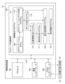
- FIG. 1 is a functional block diagram schematically showing the functional configuration of the information processing device 10 according to the embodiment of the present disclosure.
- the information processing device 10 is a device that executes region extraction processing for extracting a defect region from an image IM of an industrial product to be inspected and displays the processing result on the display device 34 .
- the information processing device 10 can be realized by a combination of computer hardware and software.
- Software is synonymous with program.
- a computer functioning as the information processing apparatus 10 may be a workstation, a personal computer, a tablet terminal, or a server.
- the information processing apparatus 10 includes an image acquisition unit 12, an area extraction unit 14, a position information generation unit 16, a rectangular frame generation unit 17, a size determination unit 18, a display mode selection unit 20, and a display control unit 22. ,including.
- the information processing device 10 can also be connected to the input device 32 and the display device 34 .
- the “connection” is not limited to wired connection, and may be wireless connection.
- the image acquisition unit 12 receives input of the image IM to be processed and acquires the image IM.
- the image IM is, for example, an X-ray transmission image obtained by irradiating X-rays on a metal part as an object to be inspected.
- the image acquisition unit 12 may include a communication interface for receiving an image IM from an external device such as a photographing device or an image management server, or a medium for reading the image IM from removable media such as a memory card. It may be configured including an interface. Further, the image acquisition unit 12 may be configured including an image acquisition program for automatically acquiring the image IM from an external device. The image IM acquired via the image acquiring section 12 is sent to the area extracting section 14 .
- the area extraction unit 14 is an AI processing unit that performs area extraction processing on the image IM using the segmentation model SM, and extracts a defect area as a detection target from the image IM.
- the segmentation model SM is a learning model trained using machine learning to perform the task of image segmentation.
- the image IM is divided into regions by classifying whether it is a defective region or not.
- Defects in cast or forged metal parts or welded metal parts include, for example, at least one of air bubbles, porosity, FMLD (Foreign material less dense) and FMLD (Foreign material more dense) .
- FMLD is the contamination of foreign matter (low density) defects that appear black in an X-ray transmission image.
- FMMD is the contamination of foreign matter (high density) defects that appear white in an X-ray transmission image.
- the segmentation model SM may be a model that classifies and detects two classes of whether each pixel is a defective area or not, or a model that performs multi-class classification detection such as what type of defect each pixel is. It may be a model that performs classification detection of
- the segmentation model SM is constructed using, for example, a convolutional neural network (CNN) having convolutional layers.
- CNN convolutional neural network
- FCN Fully Convolution Network
- FCN Fully Convolution Network
- the segmentation model SM optimizes the parameters of the learning model by machine learning using a learning data set containing a large number of learning data (training data) associated with learning images and correct data for the images. ing.
- the correct data here is data indicating the defect area existing in the image, and may be, for example, a mask image in which the defect area is filled.
- the segmentation model SM For the received image IM, the segmentation model SM generates a score indicating the probability of classification, that is, the likelihood of a defect, for each pixel in the image IM.
- the region extraction unit 14 includes a segmentation mask generation unit 15 that generates a segmentation mask based on the scores generated by the segmentation model SM.
- a segmentation mask is a mask image in which the defect area in the image IM is filled, and represents the shape of the extracted defect in pixel units.
- the segmentation mask generation unit 15 binarizes the pixel value using a threshold for the score indicating the defect-likeness of each pixel obtained by the segmentation model SM, and generates a cluster of pixels (connected region) where defect-like things are connected.
- a segmentation mask is generated by labeling as regions of the same defect for .
- a plurality of defect areas may be extracted from one image IM. In that case, a segmentation mask is generated for each of the plurality of extracted defect regions.
- segmentation model SM and the segmentation mask generator 15 are shown separately in FIG. 1, the segmentation mask generator 15 may be incorporated in the segmentation model SM.
- a segmentation mask obtained by image segmentation in the area extracting unit 14 or data labeled with a defect label can be area information of a defect extracted from the image IM.
- the position information generation unit 16 generates position information indicating the position (detection position) of the defect area based on the defect area information obtained by the process of the area extraction unit 14 .
- position information is generated for each of the multiple defect areas.
- the position information may be, for example, image coordinates indicating the position of the center of gravity of the defect area, or image coordinates indicating the position of the center of the circumscribing rectangle of the defect area.
- Generating location information from area information may be understood as converting area information to location information.
- the rectangular frame generation unit 17 Based on the position information generated by the position information generation unit 16, the rectangular frame generation unit 17 generates a rectangular frame surrounding the detection position of the defect indicated by the position information. For example, the rectangular frame generator 17 generates a rectangular frame centered on the barycentric coordinates of the extracted defect area. In addition, a "rectangle" includes a square. This rectangular frame is displayed on the display screen of the display device 34 as information visually appealing and notifying the detection position of the defect. From the viewpoint of suppressing oversight of detected defects, it is desirable that the rectangular frame has a rectangular size that is easy to visually recognize on the display screen. The size of the rectangular frame may be a predetermined fixed size.
- the size determination unit 18 determines the size of the defect, and depending on the result of the determination, there are two display modes: a mode in which a rectangular frame is displayed, and a mode in which a segmentation mask is displayed without displaying the rectangular frame. is switched.
- the position information generation unit 16 may generate position information for all of the defect areas extracted by the area extraction unit 14, or based on the determination result of the size determination unit 18, when it is necessary to display a rectangular frame. Location information may be generated.
- the rectangular frame generation unit 17 may generate a rectangular frame for all of the defect regions extracted by the region extraction unit 14, or it is necessary to display the rectangular frame based on the determination result of the size determination unit 18. A rectangular frame may be generated in such a case.
- the size of the defect determined by the size determination unit 18 includes a detection size representing the size of the defect area extracted by the area extraction unit 14 and a display size representing the size of the defect area displayed on the display screen of the display device 34. and can be.
- the size determination section 18 includes a detection size determination section 24 and a display size determination section 25 .
- the detection size determination unit 24 determines the size (detection size) of the defect area extracted by the area extraction unit 14 .
- the detection size determining unit 24 can obtain the area of the defect area by, for example, counting the number of pixels in the defect area for each extracted defect area.
- the detection size may be represented by a count value of pixels in the defect area, or may be represented by an area unit obtained by multiplying the count value by the area of one pixel.
- the detected size determination unit 24 compares the detected size with the first reference size Th1, and provides the display mode selection unit 20 with the comparison result. If the detected size is smaller than the first reference size Th1, it is determined that there is a high possibility of oversight.
- the display size determination unit 25 determines the size (display size) of the defect area displayed on the display screen of the display device 34 .
- the visibility of the defect area on the actual display screen may differ depending on the display conditions such as the specifications of the display device 34 including the screen size and resolution of the display device 34 and the display magnification specified by the input device 32 .
- the display size determination unit 25 may acquire information (display condition information) regarding display conditions including specifications from the display device 34 , or may receive information input from the input device 32 .
- the display size determination unit 25 evaluates the display size of the defect area on the display screen based on the defect area information and the display conditions, and outputs the comparison result between the display size and the second reference size Th2 to the display mode selection unit 20. offer. If the display size is smaller than the second reference size Th2, it is determined that there is a high possibility of being overlooked.
- the display mode selection unit 20 performs a process of selecting a display mode of the region extraction processing result by the region extraction unit 14 based on the determination result of the size determination unit 18 . That is, the display mode selection unit 20 performs processing for switching between a first display mode in which a rectangular frame is displayed and a second display mode in which a segmentation mask is displayed, according to the determination result of the size determination unit 18 . Selecting a display aspect may be understood to determine a display aspect. The display mode is changed by selecting a different display mode.
- the first display mode is sometimes called the rectangular frame method
- the second display mode is sometimes called the painting method.
- the coloring method may be rephrased as a fill-in method or a segmentation mask method.
- the rectangular frame method is not limited to displaying a rectangular frame without displaying a segmentation mask, and may be a display method including displaying a rectangular frame while displaying a segmentation mask.
- the coloring method is a display method in which a segmentation mask is displayed without displaying a rectangular frame. Switching between the rectangular frame method and the coloring book method includes the concept of switching whether or not to display the rectangular frame.
- the display control unit 22 performs processing for generating display data necessary for displaying the processing result according to the selection result by the display mode selection unit 20, and performs display control on the display device 34.
- the resolution (recording resolution) of the image IM is greater than the screen resolution (monitor resolution) of the display device 34, that is, when the resolution of the image IM is higher than the resolution of the display device 34, the image IM is displayed on the display device 34.
- data of the image IM is thinned out and displayed. Then, if necessary, an instruction for enlarged display or reduced display is received, and the display magnification is changed according to the instruction to perform enlarged display or reduced display.
- the display control unit 22 includes a display magnification control unit 28.
- the display magnification control unit 28 performs display enlargement processing or display reduction processing according to instructions received via the input device 32 .
- the display magnification control unit 28 can change the display magnification within the range of 10% to 500% according to the designation from the input device 32.
- a configuration in which the display magnification is fixed is not limited to the configuration in which the display magnification can be changed. In that case, processing units such as the display magnification control unit 28 and the display size determination unit 25 may be omitted.
- the input device 32 is configured by, for example, a keyboard, mouse, multi-touch panel, or other pointing device, voice input device, or an appropriate combination thereof.
- the display device 34 is configured by, for example, a liquid crystal display, an organic electro-luminescence (OEL) display, a projector, or an appropriate combination thereof.
- the input device 32 and the display device 34 may be integrally configured like a touch panel.
- the input device 32 and the display device 34 may be an input device and a display device of a terminal device connected to the information processing device 10 via a communication line.
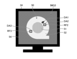
- FIG. 2 shows a metal component 50, which is an object to be inspected.
- the metal part 50 is formed by, for example, casting or forging, and includes a first part portion 51 having a relatively thin wall thickness and a second part portion 52 having a thicker wall thickness than the first part portion. and
- the area outside the metal part 50 in the inspection image IMG1 is the background 54 area.
- a defect is detected in the second component portion 52 of the metal component 50, and a segmentation mask indicating area information of the detected defect area DA1 is displayed. If the extracted defect area DA1 is larger than the first reference size and the segmentation mask is displayed in a size that is sufficiently visible on the display screen of the display device 34, as shown in FIG. A segmentation mask filled with is displayed.
- the color used for filling should be a chromatic color that contributes to visual differentiation from the surrounding non-defect areas (areas other than defects). preferable. At least one of the hue, lightness, and saturation of the segmentation mask is changed between when a defect is detected in the first component portion 51 and when a defect is detected in the second component portion 52. good too.
- the display of the segmentation mask may be a blinking display (intermittent display).
- FIG. 3 is a display example of an inspection image IMG2 in which minute defects are detected. If the detected defect area DA2 is smaller than the first reference size Th1, and even if the segmentation mask is displayed, it becomes too small to be visually recognized on the display screen of the display device 34, as shown in FIG. , a rectangular frame RF2 is displayed to visually appeal and notify the detection position of the defect area DA2. For example, when the display size is several pixels or less on the display screen, the rectangular frame RF2 is displayed. The display of the rectangular frame RF2 may be a blinking display.
- FIG. 4 is a display example of an inspection image IMG3 in which multiple defects are detected.
- segmentation mask display and rectangular frame display are mixed in correspondence with the size of the detected defect.
- a segmentation mask is displayed for the defect area DA1 extracted in the inspection image IMG3, as in FIG. , RF3 are displayed.
- the display of the rectangular frames RF2 and RF3 may be a blinking display, and the display of the segmentation mask may be a constant display (non-blinking display).
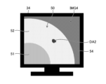
- FIG. 5 is a display example of an inspection image IMG4 in which a part of the inspection image IMG2 in FIG. 3 is enlarged and displayed.
- the display size of the defective area DA2 becomes larger than the second reference size Th2 due to the enlarged display
- the display of the rectangular frame RF2 in FIG. 3 is switched to the coloring method as shown in FIG.
- a segmentation mask is displayed showing the region information for the .
- the display is switched from the coloring book method to the rectangular frame method.
- the size of the rectangular frame displayed on the display screen may be fixed.
- FIGS. 2 to 5 show inspection images of the metal component 50 formed by casting or forging, the same applies to detecting welding defects from X-ray transmission images of welded metal components.
- FIG. 6 is a block diagram showing a hardware configuration example of the information processing apparatus 10 according to the embodiment.
- the information processing apparatus 10 includes a processor 102 , a non-transitory tangible computer-readable medium 104 , a communication interface 106 , and an input/output interface 108 .
- the processor 102 includes a CPU (Central Processing Unit). Processor 102 may include a GPU (Graphics Processing Unit). Processor 102 is coupled to computer-readable media 104 , communication interface 106 , and input/output interface 108 via bus 110 .
- CPU Central Processing Unit
- GPU Graphics Processing Unit
- the input device 32 and display device 34 are connected to the bus 110 via the input/output interface 108 .
- the computer-readable medium 104 includes a memory as a main memory and a storage as an auxiliary memory.
- Computer readable medium 104 may be, for example, a semiconductor memory, a hard disk drive (HDD) device, a solid state drive (SSD) device, or a combination of some of these.
- HDD hard disk drive
- SSD solid state drive
- the computer-readable medium 104 stores various programs and data including an area extraction program 114, a position information generation program 116, a rectangular frame generation program 117, a size determination program 118, a display mode selection program 120, and a display control program 122.
- program includes the concept of program modules.
- Region extraction program 114 includes segmentation model SM and segmentation mask generation program 115 .
- the area extraction program 114 is a program that causes the processor 102 to realize the function of the area extraction unit 14 .
- the position information generation program 116, the rectangular frame generation program 117, the size determination program 118, the display mode selection program 120, and the display control program 122 provide the processor 102 with the position information generation unit 16, the rectangular frame generation unit 17, the size determination unit, and the like.
- FIG. 7 is a flow chart showing example 1 of the operation in the information processing apparatus 10 according to the embodiment.
- the flowchart of FIG. 7 can be applied, for example, to a device configuration in which the display magnification is fixed, or to a case where the display magnification is set to 100%.
- step S11 the processor 102 acquires an image to be processed.
- step S12 the processor 102 performs region extraction processing for extracting a defect region from the acquired image using the segmentation model SM.
- step S13 the processor 102 generates position information from the defect area information obtained by the area extraction process.
- step S14 the processor 102 determines whether the size of the defect (detection size) ascertained from the area information is smaller than the first reference size Th1. If the determination result in step S14 is Yes, that is, if the detected size is smaller than the first reference size Th1, the processor 102 proceeds to step S16.
- step S16 the processor 102 employs a rectangular frame method to display a rectangular frame indicating the position (detection position) of the defect based on the position information.
- step S14 determines whether the determination result in step S14 is No, that is, if the detected size is larger than the first reference size Th1 or if the detected size is equal to the first reference size Th1, the processor 102 proceeds to step S18.
- step S14 when the detected size is equal to the first reference size Th1, it is possible to proceed to step S16 instead of step S18.
- step S18 the processor 102 adopts the coloring method and displays the segmentation mask without displaying the rectangular frame.
- steps S14 to S18 are performed for each defective area.
- step S16 or step S18 the processor 102 ends the flowchart of FIG.
- FIG. 8 is a flow chart showing example 2 of the operation in the information processing apparatus 10 according to the embodiment.
- steps common to those in FIG. 7 are denoted by the same step numbers, and overlapping descriptions are omitted.
- the flowchart of FIG. 8 may be applied. A different point from FIG. 7 about FIG. 8 is demonstrated.
- step S13 of FIG. 7 is performed as step S15 after the Yes determination of step S14. That is, after step S12 of FIG. 8, the processor 102 proceeds to step S14 to determine the detection size. When the determination result of step S14 is Yes determination, the processor 102 proceeds to step S15.
- step S15 the processor 102 generates position information from the defect area information obtained by the area extraction process. After step S15, the processor 102 proceeds to step S16 and causes the rectangular frame to be displayed.
- step S14 determines whether the segmentation mask is displayed. If the determination result of step S14 is No, the processor 102 proceeds to step S18 to display the segmentation mask.
- step S16 or step S18 the processor 102 terminates the flowchart of FIG.
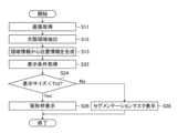
- FIG. 9 is a flow chart showing example 3 of the operation in the information processing apparatus 10 according to the embodiment. 9 can be applied to, for example, a form that does not include the detection size determination unit 24.
- the flowchart of FIG. 9 includes steps S22 to S28 instead of steps S14 to S18 of FIG.
- step S13 the processor 102 proceeds to step S22.
- step S22 the processor 102 acquires display conditions.
- specifications of the display device 34 may be stored in the computer-readable medium 104 in advance.
- step S24 the processor 102 calculates the display size of the defect based on the extracted defect region information and display conditions, and determines whether the display size is smaller than the second reference size Th2. judge.
- step S24 is Yes, that is, when the display size is smaller than the second reference size Th2, the processor 102 proceeds to step S26.
- Step S26 is the same processing as step S16 in FIG.
- step S24 determines whether the display size is larger than the second reference size Th2 or if the display size is equal to the second reference size Th2.
- step S28 is the same processing as step S18 in FIG. In step S24, it is also possible to proceed to step S26 instead of step S28 when the display size is equal to the second reference size Th2.
- steps S24 to S28 are performed for each defective area.
- step S13 may be performed after the Yes determination of step S24 (between steps S24 and S26), as in FIG.
- FIG. 10 is a flowchart showing Example 4 of the operation in the information processing apparatus 10 according to the embodiment.
- the flowchart of FIG. 10 is an example of controlling the display mode by utilizing both the detection size determination unit 24 and the display size determination unit 25 .
- steps common to those of FIGS. 7 and 9 are denoted by the same step numbers, and overlapping descriptions are omitted. A different point from FIG. 7 is demonstrated about FIG.
- the flowchart of FIG. 10 includes steps S22, S24 and S28 instead of step S18 of FIG. 7, and step S26 instead of step S16 of FIG. That is, when the determination result of step S14 is No determination, the processor 102 progresses to step S22 and acquires display conditions.
- step S24 determines whether the segmentation mask is displayed. If the determination result of step S24 is Yes determination, the processor 102 proceeds to step S26 to display a rectangular frame. On the other hand, if the determination result in step S24 is No, the processor 102 proceeds to step S28 to display the segmentation mask.
- steps S14 to S28 are performed for each defective area.
- step S26 or step S28 the processor 102 terminates the flowchart of FIG. 10, as in FIG. 8, the process of step S13 may be performed after the Yes determination in step S14 and after the Yes determination in step S24.
- FIG. 11 is a flow chart showing example 5 of the operation in the information processing apparatus 10 according to the embodiment.
- the flowchart of FIG. 11 is an example of control for switching between the rectangular frame method and the painting method in conjunction with the enlargement or reduction operation.
- the flowchart in FIG. 11 is executed after any one of the flowcharts in FIGS. 7 to 10 is executed.
- the processor 102 accepts an instruction regarding display.
- the user can input an instruction to change the display magnification, an instruction to end the display, or the like from the input device 32 .
- step S32 the processor 102 determines whether or not an instruction to change the display magnification has been received.
- the processor 102 proceeds to step S34.
- Steps S34, S36 and S38 are processes equivalent to steps S24, S26 and S28 described in FIG.
- step S34 the processor 102 determines the display size of the defect on the display screen using the specified display magnification. If the display size is smaller than the second reference size Th2 and the determination result in step S34 is Yes, the processor 102 proceeds to step S36 to display a rectangular frame. On the other hand, if the determination result in step S34 is No, that is, if the display size is larger than the second reference size Th2 or if the display size is equal to the second reference size Th2, the processor 102 proceeds to step S38. , to display the segmentation mask.
- step S36 or step S38 the processor 102 proceeds to step S39.
- the processes of steps S34 to S38 are performed for each defective area.
- the processor 102 progresses to step S39.
- step S39 the processor 102 determines whether or not to end the display.
- the processor 102 returns to step S31.
- the processor 102 ends the flowchart of FIG.
- the processor 102 may execute processing corresponding to the received instruction when receiving an instruction other than changing the display magnification and ending the display.
- a rectangular frame is displayed as information for notifying the detection position of a defect
- the manner in which the information for notifying the detection position is visually appealing and displayed is not limited to the rectangular frame.
- a circular frame, another polygonal frame, or a closed curve may be used.
- the information indicating the detection position is not limited to being displayed as an enclosing frame, but may be displayed by displaying the frame with dashed lines, for example, by displaying bracket marks indicating the four corners of a rectangle, or by displaying arrow marks. You can
- an example of segmentation mask display has been described as a form of displaying area information including the shape feature of a defect, but the form of displaying area information is not limited to a segmentation mask.
- the outline (bordering) of the defective area may be generated based on the area information, and the outline of the defective area may be displayed instead of or in addition to the segmentation mask.
- the image to be processed is not limited to an X-ray transmission image, and may be an image generated by receiving reflected light of light such as visible light and/or infrared light with an image sensor, or a scanning electron microscope. (Scanning Electron Microscope: SEM) may be used.
- the image is not limited to a two-dimensional image, and may be a three-dimensional image such as a three-dimensional CT (Computed Tomography) image obtained by three-dimensionally reconstructing a large number of continuously obtained two-dimensional slice images.
- CT Computer Tomography
- FIG. 12 is a block diagram schematically showing a configuration example of the imaging system 500.
- the imaging system 500 is for imaging an object to be inspected OBJ placed in an imaging room 514, and includes an imaging control unit 502, an imaging operation unit 504, an image recording unit 506, a camera 508, and radiation sources 510 and 512. I have.
- a shooting control unit 502 includes a CPU that controls the operation of each unit of the shooting system 500 .
- An imaging control unit 502 receives an operation input from an operator (photographer) via an imaging operation unit 504, and transmits a control signal corresponding to the operation input to each unit of the imaging system 500 to control the operation of each unit.
- the imaging operation unit 504 includes an input device that receives operation inputs from the operator. Via the imaging operation unit 504, the operator inputs information about the object to be inspected OBJ, inputs instructions for imaging conditions to the camera 508 and instructions to execute imaging, inputs instructions for radiation irradiation conditions for the radiation sources 510 and 512, An instruction to record an image obtained by shooting in the image recording unit 506 can be input.
- the shooting conditions include, for example, shooting conditions such as exposure time, focal length, and aperture, shooting angle, shooting location, and the like.
- Radiation irradiation conditions include irradiation start time, irradiation duration, irradiation angle, irradiation intensity, and the like.
- the image recording unit 506 records image data (light receiving image) of the object to be inspected OBJ photographed by the camera 508 .
- Information for identifying the object to be inspected OBJ is recorded in the image recording unit 506 in association with the image data.
- a camera 508 and radiation sources 510 and 512 are arranged inside an imaging room 514 .
- the radiation sources 510 and 512 are, for example, X-ray sources, and the partition walls and entrances between the imaging room 514 and the outside are X-ray protected by X-ray protective materials (for example, lead, concrete, etc.). there is In the case of irradiating the object OBJ with visible light for imaging, it is not necessary to use the protected imaging room 514 .
- the radiation sources 510 and 512 irradiate the object OBJ placed in the imaging room 514 with radiation according to instructions from the imaging control unit 502 .
- the camera 508 irradiates the object to be inspected OBJ from the radiation source 510 and is reflected by the object to be inspected OBJ, or the radiation emitted from the radiation source 512 to the object to be inspected OBJ. receives the radiation transmitted through the object to be inspected OBJ, and photographs the object to be inspected OBJ.
- the object to be inspected OBJ is held in an imaging room 514 by a holding member (for example, a manipulator, a mounting table, or a movable mounting table) (not shown).
- the distance and angle to 512 are adjustable. The operator can control the relative positions of the object to be inspected OBJ, the camera 508, and the radiation sources 510 and 512 via the imaging control unit 502, so that a desired portion of the object to be inspected OBJ can be imaged.
- the radiation sources 510 and 512 finish irradiating the object to be inspected OBJ with radiation in synchronization with the completion of imaging by the camera 508 .
- the camera 508 is arranged inside the imaging room 514, but the camera 508 can be arranged outside if the object to be inspected OBJ in the imaging room 514 can be photographed.
- one camera 508 and two radiation sources 510 and 512 are provided, but the number of cameras and radiation sources is not limited to this. For example, there may be multiple cameras and radiation sources, or there may be one each.
- the imaging control unit 502, the imaging operation unit 504, and the image recording unit 506 can be implemented using a combination of computer hardware and software.
- the information processing apparatus 10 may be communicably connected to the imaging system 500 , or may be configured to function as the imaging control section 502 , the imaging operation section 504 and the image recording section 506 of the imaging system 500 . may
- a program that causes a computer to implement some or all of the processing functions of the information processing device 10 is recorded on a computer-readable medium that is a non-temporary information storage medium that is an optical disk, magnetic disk, semiconductor memory, or other tangible object, and this It is possible to provide the program through an information storage medium.
- a part or all of the processing functions of the information processing device 10 may be realized by cloud computing, or may be provided as a SasS (Software as a Service) service.
- SasS Software as a Service
- the hardware structure of the processing unit that executes various processes includes, for example, the following various processors: ).
- processors include CPUs, which are general-purpose processors that run programs and function as various processing units, GPUs, which are processors specialized for image processing, and FPGAs (Field Programmable Gate Arrays).
- PLD Programmable Logic Device
- ASIC Application Specific Integrated Circuit
- a single processing unit may be composed of one of these various processors, or may be composed of two or more processors of the same type or different types.
- one processing unit may be configured by a plurality of FPGAs, a combination of CPU and FPGA, or a combination of CPU and GPU.
- a plurality of processing units may be configured by one processor.
- a single processor is configured by combining one or more CPUs and software. There is a form in which a processor functions as multiple processing units.
- SoC System On Chip
- the various processing units are configured using one or more of the above various processors as a hardware structure.
- the hardware structure of these various processors is, more specifically, an electrical circuit that combines circuit elements such as semiconductor elements.
- the information processing apparatus 10 has the following advantages.
- the area extraction type AI represented by the segmentation model SM can extract the detection target area from the image with high accuracy, and it is possible to detect minute and weak defects and grasp the shape of the defect.
- the information processing apparatus 10 determines the detection size ascertained from the area information of the defect extracted by the area extraction process, and the display size of the defect ascertained based on the detection size and display conditions on the display screen.
- the mode of display (display method) for the occurring defect is controlled according to the size of at least one of them. Since minute and weak defects that are easily overlooked are displayed in easily visible rectangular frames, overlooking is suppressed, and there is an effect that defects can be visually evaluated without omission.
- the information processing device 10 performs image processing using AI from an X-ray transmission image obtained by imaging various minute and weak defects that occur during molding of metal parts by casting or forging and welding with X-rays.
- a defect signal can be automatically detected (extracted), and defect information can be presented to an inspector in an easy-to-visual form.
- the technique of controlling the display of defect detection results realized by the information processing apparatus 10 is not limited to defect detection, and can be applied to various fields.
- the processing functions of the information processing device 10 may be realized using a plurality of information processing devices.
- a computer system in which a first information processing device and a second information processing device are connected via a communication line is adopted, and the first information processing device includes an image acquisition unit 12, a region extraction unit 14, The processing functions of the position information generation unit 16 are implemented, and the processing functions of the rectangular frame generation unit 17, the size determination unit 18, the display mode selection unit 20, and the display control unit 22 are implemented in the second information processing device.
- the communication line may be a local area network or a wide area network.
- the first information processing apparatus generates area information and position information of the defect to be detected from the image to be processed.
- the second information processing device acquires the defect area information and position information generated by the first information processing device, and switches the display mode according to the determination result of the size determination unit 18 .
- Display data obtained through processing by the second information processing device can be transmitted to another terminal device via a communication line, and the processing result can be displayed on the display device of the terminal device. .
- Information processing device 12 Image acquisition unit 14 Region extraction unit 15 Segmentation mask generation unit 16 Position information generation unit 17 Rectangular frame generation unit 18 Size determination unit 20 Display mode selection unit 22 Display control unit 24 Detection size determination unit 25 Display size determination unit 28 display magnification control unit 32 input device 34 display device 50 metal component 51 first component portion 52 second component portion 54 background 102 processor 104 computer readable medium 106 communication interface 108 input/output interface 110 bus 114 region extraction program 115 segmentation mask Generation program 116 Position information generation program 117 Rectangular frame generation program 118 Size determination program 120 Display mode selection program 122 Display control program 500 Imaging system 502 Imaging control unit 504 Imaging operation unit 506 Image recording unit 508 Camera 510 Radiation source 512 Radiation source 514 Imaging Room SM Segmentation model DA1, DA2, DA3 Defect area RF2, RF3 Rectangular frame IM Image IMG1, IMG2, IMG3, IMG4 Inspection image OBJ Object to be inspected S11 to S39 Steps of information processing method
Landscapes
- Engineering & Computer Science (AREA)
- Theoretical Computer Science (AREA)
- General Physics & Mathematics (AREA)
- Physics & Mathematics (AREA)
- Computer Vision & Pattern Recognition (AREA)
- General Engineering & Computer Science (AREA)
- Multimedia (AREA)
- Human Computer Interaction (AREA)
- Biochemistry (AREA)
- Chemical & Material Sciences (AREA)
- Analytical Chemistry (AREA)
- Life Sciences & Earth Sciences (AREA)
- General Health & Medical Sciences (AREA)
- Immunology (AREA)
- Pathology (AREA)
- Health & Medical Sciences (AREA)
- Computer Hardware Design (AREA)
- Quality & Reliability (AREA)
- Image Analysis (AREA)
- Analysing Materials By The Use Of Radiation (AREA)
Priority Applications (4)
| Application Number | Priority Date | Filing Date | Title |
|---|---|---|---|
| JP2023550449A JPWO2023053768A1 (https=) | 2021-09-28 | 2022-08-19 | |
| EP22875640.9A EP4411353A4 (en) | 2021-09-28 | 2022-08-19 | Information processing device, information processing method, and program |
| CN202280063705.0A CN118076884A (zh) | 2021-09-28 | 2022-08-19 | 信息处理装置、信息处理方法及程序 |
| US18/617,584 US20240242374A1 (en) | 2021-09-28 | 2024-03-26 | Information processing apparatus, information processing method, and program |
Applications Claiming Priority (2)
| Application Number | Priority Date | Filing Date | Title |
|---|---|---|---|
| JP2021-158214 | 2021-09-28 | ||
| JP2021158214 | 2021-09-28 |
Related Child Applications (1)
| Application Number | Title | Priority Date | Filing Date |
|---|---|---|---|
| US18/617,584 Continuation US20240242374A1 (en) | 2021-09-28 | 2024-03-26 | Information processing apparatus, information processing method, and program |
Publications (1)
| Publication Number | Publication Date |
|---|---|
| WO2023053768A1 true WO2023053768A1 (ja) | 2023-04-06 |
Family
ID=85782297
Family Applications (1)
| Application Number | Title | Priority Date | Filing Date |
|---|---|---|---|
| PCT/JP2022/031319 Ceased WO2023053768A1 (ja) | 2021-09-28 | 2022-08-19 | 情報処理装置、情報処理方法及びプログラム |
Country Status (5)
| Country | Link |
|---|---|
| US (1) | US20240242374A1 (https=) |
| EP (1) | EP4411353A4 (https=) |
| JP (1) | JPWO2023053768A1 (https=) |
| CN (1) | CN118076884A (https=) |
| WO (1) | WO2023053768A1 (https=) |
Cited By (1)
| Publication number | Priority date | Publication date | Assignee | Title |
|---|---|---|---|---|
| WO2025023191A1 (ja) * | 2023-07-21 | 2025-01-30 | 富士フイルム株式会社 | 制御装置、制御方法、及び制御プログラム |
Citations (8)
| Publication number | Priority date | Publication date | Assignee | Title |
|---|---|---|---|---|
| JPH0792094A (ja) * | 1993-09-21 | 1995-04-07 | Toshiba Corp | パターン欠陥検査装置 |
| JP2005077324A (ja) * | 2003-09-02 | 2005-03-24 | Toyota Motor Corp | 鋳造内部欠陥検査支援装置および方法 |
| JP2009186271A (ja) * | 2008-02-05 | 2009-08-20 | Shimadzu Corp | X線検査装置 |
| JP2015203628A (ja) * | 2014-04-15 | 2015-11-16 | 株式会社日立ハイテクノロジーズ | 荷電粒子線装置及び座標補正方法 |
| WO2016174926A1 (ja) | 2015-04-30 | 2016-11-03 | 富士フイルム株式会社 | 画像処理装置及び画像処理方法及びプログラム |
| WO2017130550A1 (ja) | 2016-01-29 | 2017-08-03 | 富士フイルム株式会社 | 欠陥検査装置、方法およびプログラム |
| WO2020003917A1 (ja) * | 2018-06-29 | 2020-01-02 | 富士フイルム株式会社 | 欠陥表示装置及び方法 |
| JP2020144688A (ja) * | 2019-03-07 | 2020-09-10 | 株式会社Ihi | 学習方法、学習装置、及び当該学習装置を備える溶接欠陥検出装置 |
Family Cites Families (1)
| Publication number | Priority date | Publication date | Assignee | Title |
|---|---|---|---|---|
| CN115104128B (zh) * | 2020-03-02 | 2025-03-21 | 富士胶片株式会社 | 图像处理装置、图像处理方法及图像处理程序 |
-
2022
- 2022-08-19 EP EP22875640.9A patent/EP4411353A4/en active Pending
- 2022-08-19 CN CN202280063705.0A patent/CN118076884A/zh active Pending
- 2022-08-19 JP JP2023550449A patent/JPWO2023053768A1/ja active Pending
- 2022-08-19 WO PCT/JP2022/031319 patent/WO2023053768A1/ja not_active Ceased
-
2024
- 2024-03-26 US US18/617,584 patent/US20240242374A1/en active Pending
Patent Citations (8)
| Publication number | Priority date | Publication date | Assignee | Title |
|---|---|---|---|---|
| JPH0792094A (ja) * | 1993-09-21 | 1995-04-07 | Toshiba Corp | パターン欠陥検査装置 |
| JP2005077324A (ja) * | 2003-09-02 | 2005-03-24 | Toyota Motor Corp | 鋳造内部欠陥検査支援装置および方法 |
| JP2009186271A (ja) * | 2008-02-05 | 2009-08-20 | Shimadzu Corp | X線検査装置 |
| JP2015203628A (ja) * | 2014-04-15 | 2015-11-16 | 株式会社日立ハイテクノロジーズ | 荷電粒子線装置及び座標補正方法 |
| WO2016174926A1 (ja) | 2015-04-30 | 2016-11-03 | 富士フイルム株式会社 | 画像処理装置及び画像処理方法及びプログラム |
| WO2017130550A1 (ja) | 2016-01-29 | 2017-08-03 | 富士フイルム株式会社 | 欠陥検査装置、方法およびプログラム |
| WO2020003917A1 (ja) * | 2018-06-29 | 2020-01-02 | 富士フイルム株式会社 | 欠陥表示装置及び方法 |
| JP2020144688A (ja) * | 2019-03-07 | 2020-09-10 | 株式会社Ihi | 学習方法、学習装置、及び当該学習装置を備える溶接欠陥検出装置 |
Non-Patent Citations (1)
| Title |
|---|
| See also references of EP4411353A4 |
Cited By (1)
| Publication number | Priority date | Publication date | Assignee | Title |
|---|---|---|---|---|
| WO2025023191A1 (ja) * | 2023-07-21 | 2025-01-30 | 富士フイルム株式会社 | 制御装置、制御方法、及び制御プログラム |
Also Published As
| Publication number | Publication date |
|---|---|
| EP4411353A4 (en) | 2025-02-19 |
| JPWO2023053768A1 (https=) | 2023-04-06 |
| EP4411353A1 (en) | 2024-08-07 |
| CN118076884A (zh) | 2024-05-24 |
| US20240242374A1 (en) | 2024-07-18 |
Similar Documents
| Publication | Publication Date | Title |
|---|---|---|
| US11386542B2 (en) | Training data creation method and device, and defect inspection method and device | |
| CN111325739B (zh) | 肺部病灶检测的方法及装置,和图像检测模型的训练方法 | |
| US20100220910A1 (en) | Method and system for automated x-ray inspection of objects | |
| US11010890B2 (en) | Method for the non-destructive testing of the volume of a test object and testing device configured for carrying out such a method | |
| US8345949B2 (en) | Sequential approach for automatic defect recognition | |
| US20210072165A1 (en) | Defect display device and method | |
| CN115713476B (zh) | 基于激光焊接的视觉检测方法、装置及可读存储介质 | |
| TW202240546A (zh) | 用於自動視覺檢查之圖像增強技術 | |
| JP6317725B2 (ja) | 取得された画像内のクラッタを決定するためのシステム及び方法 | |
| US20240311994A1 (en) | Training data generation device, training data generation method, program, and defect test device | |
| US20240242374A1 (en) | Information processing apparatus, information processing method, and program | |
| CN115330896A (zh) | 金属物体识别方法、系统及装置 | |
| CN105374023B (zh) | 一种分割目标区域方法,及其图像重建方法和装置 | |
| Schiele et al. | Comparison of deep learning-based image segmentation methods for the detection of voids in X-ray images of microelectronic components | |
| US12405232B2 (en) | X-ray inspection apparatus used for an inspection of a substrate, X-ray inspection system, image management method and program | |
| CN118382799A (zh) | 信息处理装置、信息处理方法、程序及记录介质 | |
| CN120543502A (zh) | 二极管封装缺陷x光图像自动判读系统及方法 | |
| US12456184B2 (en) | Use of an HDR image in a visual inspection process | |
| US12555294B2 (en) | Segmentation of computed tomography voxel data using machine learning | |
| CN108615235B (zh) | 一种对颞耳图像进行处理的方法及装置 | |
| JP2005241304A (ja) | 外観検査方法 | |
| JP7595488B2 (ja) | 情報処理装置、情報処理方法及びコンピュータプログラム | |
| US20240242330A1 (en) | Image processing apparatus, processing system, image display method, and program | |
| US20250095139A1 (en) | Information processing apparatus, information processing method, and information processing program | |
| Bjerregaard et al. | Attenuation-adjusted deep learning of pore defects in 2D radiographs of additive manufacturing powders |
Legal Events
| Date | Code | Title | Description |
|---|---|---|---|
| 121 | Ep: the epo has been informed by wipo that ep was designated in this application |
Ref document number: 22875640 Country of ref document: EP Kind code of ref document: A1 |
|
| WWE | Wipo information: entry into national phase |
Ref document number: 2023550449 Country of ref document: JP |
|
| WWE | Wipo information: entry into national phase |
Ref document number: 202280063705.0 Country of ref document: CN |
|
| NENP | Non-entry into the national phase |
Ref country code: DE |
|
| ENP | Entry into the national phase |
Ref document number: 2022875640 Country of ref document: EP Effective date: 20240429 |