WO2023053766A1 - 画像データ処理装置及び方法 - Google Patents
画像データ処理装置及び方法 Download PDFInfo
- Publication number
- WO2023053766A1 WO2023053766A1 PCT/JP2022/031317 JP2022031317W WO2023053766A1 WO 2023053766 A1 WO2023053766 A1 WO 2023053766A1 JP 2022031317 W JP2022031317 W JP 2022031317W WO 2023053766 A1 WO2023053766 A1 WO 2023053766A1
- Authority
- WO
- WIPO (PCT)
- Prior art keywords
- image data
- image
- processing device
- data processing
- matrix
- Prior art date
- Legal status (The legal status is an assumption and is not a legal conclusion. Google has not performed a legal analysis and makes no representation as to the accuracy of the status listed.)
- Ceased
Links
Images












Classifications
-
- H—ELECTRICITY
- H04—ELECTRIC COMMUNICATION TECHNIQUE
- H04N—PICTORIAL COMMUNICATION, e.g. TELEVISION
- H04N23/00—Cameras or camera modules comprising electronic image sensors; Control thereof
- H04N23/80—Camera processing pipelines; Components thereof
- H04N23/81—Camera processing pipelines; Components thereof for suppressing or minimising disturbance in the image signal generation
-
- G—PHYSICS
- G01—MEASURING; TESTING
- G01J—MEASUREMENT OF INTENSITY, VELOCITY, SPECTRAL CONTENT, POLARISATION, PHASE OR PULSE CHARACTERISTICS OF INFRARED, VISIBLE OR ULTRAVIOLET LIGHT; COLORIMETRY; RADIATION PYROMETRY
- G01J3/00—Spectrometry; Spectrophotometry; Monochromators; Measuring colours
- G01J3/28—Investigating the spectrum
- G01J3/40—Measuring the intensity of spectral lines by determining density of a photograph of the spectrum; Spectrography
-
- H—ELECTRICITY
- H04—ELECTRIC COMMUNICATION TECHNIQUE
- H04N—PICTORIAL COMMUNICATION, e.g. TELEVISION
- H04N23/00—Cameras or camera modules comprising electronic image sensors; Control thereof
- H04N23/50—Constructional details
- H04N23/55—Optical parts specially adapted for electronic image sensors; Mounting thereof
-
- H—ELECTRICITY
- H04—ELECTRIC COMMUNICATION TECHNIQUE
- H04N—PICTORIAL COMMUNICATION, e.g. TELEVISION
- H04N23/00—Cameras or camera modules comprising electronic image sensors; Control thereof
- H04N23/60—Control of cameras or camera modules
-
- H—ELECTRICITY
- H04—ELECTRIC COMMUNICATION TECHNIQUE
- H04N—PICTORIAL COMMUNICATION, e.g. TELEVISION
- H04N23/00—Cameras or camera modules comprising electronic image sensors; Control thereof
- H04N23/80—Camera processing pipelines; Components thereof
- H04N23/84—Camera processing pipelines; Components thereof for processing colour signals
-
- H—ELECTRICITY
- H04—ELECTRIC COMMUNICATION TECHNIQUE
- H04N—PICTORIAL COMMUNICATION, e.g. TELEVISION
- H04N25/00—Circuitry of solid-state image sensors [SSIS]; Control thereof
- H04N25/10—Circuitry of solid-state image sensors [SSIS]; Control thereof for transforming different wavelengths into image signals
Definitions
- the present invention relates to an image data processing apparatus and method, and more particularly to an image data processing apparatus and method for generating image data in multiple wavelength ranges.
- Imaging using a lens equipped with a bandpass filter and a polarizing filter and an image sensor equipped with a color filter and a polarizer, and processing the obtained image data to generate images of multiple wavelengths is known (for example, Patent Document 1, etc.).
- One embodiment according to the technology of the present disclosure provides an image data processing device and method capable of generating high-quality images.
- An image data processing device for processing first image data obtained by imaging, with an image sensor, light from an object that has been dispersed into a plurality of wavelengths through a bandpass filter
- the image data processing device comprising a processor, the processor comprising: Image data processing of acquiring first image data, calculating a feature amount in a transmission wavelength range of a band-pass filter based on the first image data, and calculating information on spectral characteristics of a subject based on the feature amount.
- the processor obtains the second image data, performs image generation processing on the second image data to obtain third image data based on the wavelength, and obtains third image data based on the wavelength in the transmission wavelength range of the bandpass filter based on the third image data.
- the image data processing device of any one.
- the processor calculates the output value of the pixel of each optical filter with respect to the light of each bandpass filter based on the information and the spectral sensitivity characteristic of the image sensor, and generates a first matrix whose elements are the calculated output values.
- the processor outputs the pixel output of each optical filter with respect to the light of each bandpass filter based on the spectral characteristics of the subject used when calculating the parameters used in the image generation process and the spectral sensitivity characteristics of the image sensor.
- the image data processing device which calculates the value, calculates a second matrix whose elements are the calculated output values, and generates the first data based on the first matrix and the second matrix.
- the processor calculates the output value of the pixel of each optical filter with respect to the light of each bandpass filter based on the information and the spectral sensitivity characteristic of the image sensor, and generates a first matrix whose elements are the calculated output values.
- the processor outputs pixels of each optical filter with respect to light of each band-pass filter based on the spectral characteristics of the subject used when calculating the parameters used for interference removal processing and the spectral sensitivity characteristics of the image sensor.
- the image data processing device which calculates a value, calculates a second matrix whose elements are the calculated output values, and generates the first data based on the first matrix and the second matrix.
- image data comprising the steps of: calculating a feature amount in the transmission wavelength range of the band-pass filter based on the first image data; and calculating information on the spectral characteristics of the subject based on the feature amount. Processing method.
- Diagram showing schematic configuration of multispectral camera system Front view showing a schematic configuration of the filter unit A diagram showing an example of a hardware configuration of an image data processing device.
- Block diagram of the main functions realized by the image data processing device Block diagram of the main functions of the correction data generator
- Conceptual diagram of the process of estimating the spectral characteristics of a subject from a multispectral image Conceptual diagram of processing for estimating the slope of the spectral characteristics of an object within the transmission wavelength range of a bandpass filter
- Conceptual diagram of processing to calculate the amount of interference Conceptual diagram of processing to calculate the interference matrix in a specific environment
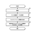
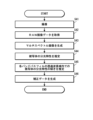
- Flowchart showing the procedure of correction data generation processing Flowchart showing the procedure for generating a multispectral image
- a diagram showing another example of a method for calculating a feature amount A diagram showing another example of a method for calculating a feature amount
- Block diagram of the main functions realized by the image data processing device Flowchart showing the procedure of interference cancellation matrix correction processing Flowchart showing the procedure for generating a multi
- FIG. 4 is a diagram showing a specific example of a method for calculating elements Cij of matrix C;
- FIG. 4 is a diagram showing a specific example of a method for calculating elements Cij of matrix C;
- Flowchart showing the procedure of correction data generation processing Flowchart showing the procedure for generating a multispectral image
- interference removal processing is performed on image data (RAW image data) obtained by imaging. Generate images of multiple wavelengths (multispectral images).
- the interference elimination process is performed by matrix calculation using predetermined parameters (interference elimination parameters).
- the interference elimination parameter is obtained in advance, for example, in a development environment that is less susceptible to ambient light other than the light source that irradiates the subject, and is obtained so that the spectral characteristics (spectrum) of the subject are uniform.
- spectral characteristics of an object in the transmission wavelength range of a band-pass filter are uniform without being affected by ambient light other than the light source.
- interference removal processing is performed using interference removal parameters obtained in advance (interference removal parameters determined in a specific environment that is less susceptible to disturbance light other than the light source, such as the above development environment), the actual There is a problem that a correct multispectral image cannot be obtained by imaging (imaging in a real environment). That is, a phenomenon (crosstalk) occurs in which information of other wavelengths is mixed. Crosstalk occurs when the amount of light varies within the transmission wavelength range of the bandpass filter between the specific environment and the actual environment. This light amount variation depends on the spectral characteristics of the subject, the light receiving sensitivity characteristics of the image sensor, and the like.
- FIG. 1 is a diagram showing a schematic configuration of a multispectral camera system.
- the multispectral camera system 1 of the present embodiment includes a multispectral camera 10 and an image data processing device 300 . Note that this figure shows an example of capturing a 3-band multispectral image.
- a multispectral camera 10 comprises a lens device 100 and a camera body 200 .
- the lens device 100 splits incident light from an object into a plurality of wavelengths. In this embodiment, incident light is split into three wavelengths.
- the lens device 100 includes a plurality of lens groups 110A and 110B and a filter unit 120. Note that FIG. 1 shows only two lens groups 110A and 110B for convenience.
- Each lens group 110A, 110B is composed of at least one lens.
- each of the lens groups 110A and 110B is represented by one lens for convenience.
- the filter unit 120 is arranged at or near the pupil position in the lens apparatus 100 .
- the vicinity of the pupil position refers to an area that satisfies the following equation.
- FIG. 2 is a front view showing a schematic configuration of the filter unit.
- the filter unit 120 includes a filter frame 122 and a plurality of band-pass filters (BPF) 123A, 123B, and 123C attached to the filter frame 122.
- BPF band-pass filters
- the filter frame 122 has a plurality of openings 122A, 122B and 122C, as shown in FIG.
- Each of the openings 122A, 122B, 122C constitutes mounting portions for the bandpass filters 123A, 123B, 123C, respectively.
- the openings 122A, 122B, and 122C have a circular shape and are arranged at regular intervals along the circumferential direction. The shape and arrangement of the openings 122A, 122B, 122C are not limited to this.
- the opening indicated by reference numeral 122A is referred to as a first opening
- the opening indicated by reference numeral 122B is referred to as a second opening
- the opening indicated by reference numeral 122C is referred to as a third opening.
- 122B, 122C is referred to as a first opening
- the opening indicated by reference numeral 122B, 122C is referred to as a second opening
- the opening indicated by reference numeral 122C is referred to as a third opening.
- Bandpass filters 123A, 123B, and 123C having different transmission wavelength ranges are attached to the openings 122A, 122B, and 122C, respectively.
- the transmission wavelength ranges of the bandpass filters 123A, 123B, and 123C attached to the openings 122A, 122B, and 122C are the wavelength ranges of the three images to be captured.
- a bandpass filter 123A that transmits light in the first wavelength band ⁇ 1 is attached to the first opening 122A.
- the bandpass filter 123A attached to the first opening 122A will be referred to as a first bandpass filter 123A to distinguish it from other bandpass filters, as required.
- a band-pass filter 123B that transmits light in the second wavelength band ⁇ 2 is attached to the second opening 122B.
- the bandpass filter 123B attached to the second opening 122B will be referred to as a second bandpass filter 123B to distinguish it from other bandpass filters, as required.
- a bandpass filter 123C that transmits light in the third wavelength band ⁇ 3 is attached to the third opening 122C.
- the band-pass filter 123C attached to the third opening 122C will be referred to as a third band-pass filter 123C to distinguish it from other band-pass filters, as required.
- the light incident on the lens device 100 is split into three wavelengths by the three bandpass filters 123A, 123B, and 123C provided in the filter unit 120.
- the camera body 200 has an image sensor 210 as shown in FIG.
- the image sensor 210 is arranged on the optical axis of the lens device 100 and receives light that has passed through the lens device 100 .
- the image sensor 210 is composed of a single-plate color image sensor equipped with a plurality of types of color filters.
- a single-plate color image sensor equipped with three types of color filters of red (Red: R), blue (Blue: B), and green (Green: G) is used.
- a color filter is an example of an optical filter.
- the color filters are regularly arranged with respect to the pixels arranged in a matrix.
- a pixel in which a red (R) color filter is arranged is referred to as a first pixel.
- a pixel in which a green (G) color filter is arranged is referred to as a second pixel.
- a pixel in which a blue (B) color filter is arranged is a third pixel.
- the image sensor has a set of three pixels, that is, the first pixel, the second pixel, and the third pixel, and this set of pixel blocks (pixel blocks) are regularly arranged. As will be described later, interference removal processing is performed in units of pixel blocks.
- the image sensor 210 is composed of, for example, a CMOS (Complementary Metal Oxide Semiconductor) type that includes a drive section, an ADC (Analog to Digital Converter), and a signal processing section.
- CMOS Complementary Metal Oxide Semiconductor
- ADC Analog to Digital Converter
- the image sensor 210 operates by being driven by a built-in driver.
- the signal of each pixel is converted into a digital signal by the built-in ADC and output.
- the signal of each pixel is output after undergoing correlated double sampling processing, gain processing, correction processing, etc. by the built-in signal processing unit.
- the signal processing may be performed after conversion into a digital signal, or may be performed before conversion into a digital signal.
- the image sensor 210 may employ a CCD (Charge-Coupled Device) type or the like in addition to the CMOS type described above.
- the camera body 200 includes an output unit (not shown) that outputs image data captured by the image sensor 210, a camera control unit (not shown) that controls the overall operation of the camera body 200, and the like.
- the camera control section is composed of, for example, a micro processing unit (MPU) having a processor and memory.
- the microprocessing unit functions as a camera control section by executing a predetermined control program.
- the image data output from the camera body 200 is so-called RAW image data. That is, unprocessed image data.
- This RAW image data is processed by the image data processing device 300 to generate an image spectrally divided into a plurality of wavelengths.
- the image data processing device 300 processes image data (RAW image data) output from the camera body 200 of the multispectral camera 10 to generate a multispectral image. More specifically, images of wavelengths corresponding to the transmission wavelength regions ⁇ 1, ⁇ 2, and ⁇ 3 of the bandpass filters 123A, 123B, and 123C mounted on the lens device 100 are generated.
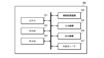
- FIG. 3 is a diagram showing an example of the hardware configuration of the image data processing device.
- the image data processing device 300 includes a CPU (Central Processing Unit) 311, a ROM (Read Only Memory) 312, a RAM (Random Access Memory) 313, an auxiliary storage device 314, an input device 315, and an output device 316. , an input/output interface (I/F) 317, etc., and has a so-called computer configuration. That is, a computer (CPU in a narrow sense) functions as the image data processing device 300 by executing a predetermined program (image data processing program).
- a predetermined program image data processing program
- the auxiliary storage device 314 constitutes a storage unit of the image data processing device 300 .
- the auxiliary storage device 314 is composed of, for example, an HDD (Hard Disk Drive), an SSD (Solid State Drive), or the like. Programs executed by the CPU 311 are stored in the auxiliary storage device 314 or the ROM 312 .
- the input device 315 constitutes an operation unit of the image data processing device 300 .
- the input device 315 is composed of, for example, a keyboard, mouse, touch panel, and the like.
- the output device 316 constitutes the display section of the image data processing device 300 .
- the output device 316 is configured by, for example, a display such as a liquid crystal display (Liquid Crystal Display) or an organic EL display (Organic Light Emitting Diode display).
- the input/output interface 317 constitutes a connection section of the image data processing device 300 .
- the image data processing device 300 is connected to the camera body 200 of the multispectral camera 10 via the input/output interface 317 .
- FIG. 4 is a block diagram of the main functions realized by the image data processing device.
- the image data processing device 300 has the functions of an image data acquisition section 320 , an image generation section 321 , an image correction section 322 , a correction data generation section 323 , an output control section 324 and a recording control section 325 .
- Each function is realized by the CPU 311 executing a predetermined program (image data processing program).
- the image data acquisition unit 320 acquires image data obtained by imaging from the multispectral camera 10 .
- the image data obtained from the multispectral camera 10 is RAW image data.
- Image data is obtained through the input/output interface 317 .
- the image generation unit 321 performs predetermined signal processing on the image data (RAW image data) acquired by the image data acquisition unit 320 to generate a multispectral image. Specifically, interference removal processing is performed on the RAW image data to generate a multispectral image.
- RAW image data acquired by the image data acquisition unit 320
- interference removal processing is performed on the RAW image data to generate a multispectral image.
- as multispectral images an image of the first wavelength region ⁇ 1 (first image), an image of the second wavelength region ⁇ 2 (second image), and an image of the third wavelength region (third image ).
- the interference elimination process is performed by performing matrix calculation for each pixel block using an interference elimination matrix.
- y1 be the output value (pixel value) of the first pixel
- y2 be the output value (pixel value) of the second pixel
- y3 be the output value (pixel value) of the third pixel.
- x1 be the pixel value of the pixel
- x2 be the pixel value of the corresponding pixel in the second image
- x3 be the pixel value of the corresponding pixel in the third image.
- Matrix A ⁇ 1 is the interference cancellation matrix.
- a matrix of 3 rows and 3 columns provides an interference cancellation matrix.
- Each element (a 11 , a 12 , . . . ) of the interference cancellation matrix A ⁇ 1 is an interference cancellation parameter.
- the interference cancellation parameter is an example of a parameter used for interference cancellation processing.
- Information on the interference cancellation parameter is stored in the auxiliary storage device 314, for example.
- the image generation unit 321 acquires the information of the interference elimination parameter from the auxiliary storage device 314, performs interference elimination processing, and generates a multispectral image.
- Interference removal processing is an example of image generation processing. Through the interference removal process, pixel values corresponding to the transmission wavelength regions of each band-pass filter are extracted, and an image (multispectral image) of each wavelength region is generated.
- the image correction unit 322 performs processing for correcting the multispectral image generated by the image generation unit 321 .
- the multispectral image generated by the image generator 321 is an image generated using the interference cancellation matrix obtained in the specific environment. Therefore, when the multispectral camera 10 is used in an environment different from the specific environment, a correct multispectral image cannot be obtained. Therefore, the multispectral image generated by the image generator 321 is corrected so that a correct multispectral image can be obtained.
- the image correction unit 322 performs this correction processing.
- the correction data generation unit 323 performs processing for generating image correction data used by the image correction unit 322 . Details of a method of generating data for image correction and a method of correcting a multispectral image using the generated data will be described later.
- the output control unit 324 controls the output of the multispectral image generated by the image generation unit 321. In this embodiment, output to the display, which is the output device 316, is controlled.
- the recording control unit 325 controls recording of the multispectral image generated by the image generation unit 321 according to instructions from the user.
- the generated multispectral image is recorded in secondary storage device 314 .
- the image generation unit 321 generates a multispectral image by performing interference removal processing on the RAW image data acquired by the image data acquisition unit 320 .
- the interference elimination matrix used in this interference elimination process is obtained in a specific environment. Normally, in a specific environment, the influence of ambient light other than the light source is eliminated, and the interference elimination matrix is obtained by making the spectral characteristics of the object uniform in the transmission wavelength range of the band-pass filter. Therefore, crosstalk occurs when the spectral characteristics of an object to be actually imaged are not uniform. Crosstalk occurs when the spectral characteristics of an object to be actually imaged have a slope in the transmission wavelength range of the bandpass filter. Therefore, in the image data processing apparatus 300 of the present embodiment, this tilt is estimated and corrected to obtain a correct multispectral image.
- FIG. 5 is a block diagram of main functions of the correction data generation section.
- the correction data generation section 323 mainly has the functions of a spectral characteristic estimation section 323A, an inclination estimation section 323B, an interference amount calculation section 323C, and a correction data calculation section 323D.
- the spectral characteristic estimation unit 323A performs processing for estimating the spectral characteristic (spectrum) of the subject from the multispectral image of the subject generated by the image generation unit 321.
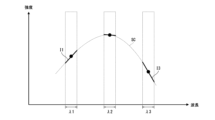
- FIG. 6 is a conceptual diagram of processing for estimating the spectral characteristics of a subject from a multispectral image.
- the intensity (brightness) of images (first image, second image, and third image) in each wavelength range ⁇ 1, ⁇ 2, and ⁇ 3 are plotted, and the subject is estimated.
- a well-known technique for example, least squares method, etc. can be adopted for curve fitting.
- the spectral characteristics of the subject are obtained by converting the intensity (brightness) information of the discretely obtained images of each wavelength band into a function.
- the spectral characteristics SC of the subject within the transmission wavelength ranges ⁇ 1, ⁇ 2, and ⁇ 3 of each bandpass filter estimated by the spectral characteristics estimation unit 323A are an example of the feature amount.
- the inclination estimation unit 323B performs processing for estimating the inclination of the subject's spectral characteristics SC within the transmission wavelength range of the band-pass filter from the subject's spectral characteristics SC estimated by the spectral characteristics estimation unit 323A.
- FIG. 7 is a conceptual diagram of processing for estimating the inclination of the spectral characteristics of the subject within the transmission wavelength range of the bandpass filter.
- the inclinations I1, I2, and I3 of the spectral characteristics SC of the subject within the transmission wavelength ranges ⁇ 1, ⁇ 2, and ⁇ 3 of the respective band-pass filters are calculated from the spectral characteristics SC of the subject estimated by the spectral characteristic estimation unit 323A.
- the gradients I1, I2, and I3 are estimated by calculating differential values at the central points of the transmission wavelength ranges ⁇ 1, ⁇ 2, and ⁇ 3. That is, the calculated differential values are estimated as the gradients I1, I2, and I3 of the spectral characteristics SC of the object within the respective wavelength ranges ⁇ 1, ⁇ 2, and ⁇ 3.
- the slopes I1, I2, and I3 of the subject's spectral characteristics SC within the transmission wavelength ranges ⁇ 1, ⁇ 2, and ⁇ 3 of the bandpass filters estimated by the slope estimating unit 323B are an example of information on the subject's spectral characteristics.
- the interference amount calculation unit 323C performs a process of calculating the interference amount (crosstalk amount) in the actual environment based on the estimated tilt and information on the spectral sensitivity characteristics of each pixel of the image sensor.
- FIG. 8 is a conceptual diagram of processing for calculating the amount of interference.
- the lens device has two bandpass filters and the image sensor has two types of color filters (pixel types) will be described.
- the two bandpass filters are BPF1 and BPF2, and the transmission wavelength ranges of the bandpass filters BPF1 and BPF2 are .LAMBDA.1 and .LAMBDA.2, respectively.
- the types of color filters provided in the image sensor are assumed to be red (R) and green (G).
- FIG. 8(A) shows the inclination of the spectral characteristics of the object within the transmission wavelength ranges ⁇ 1 and ⁇ 2 of the two bandpass filters BPF1 and BPF2.
- FIG. 8(B) shows the spectral sensitivity characteristics of the R and G pixels of the image sensor.
- the R pixel is a pixel in which a red (R) color filter is arranged.
- a G pixel is a pixel in which a green (G) color filter is arranged.
- the solid line indicates the spectral sensitivity characteristic of the R pixel.
- the dashed line indicates the spectral sensitivity characteristic of the G pixel.
- the integrated value (sensor response) of the spectral sensitivity of the subject and the spectral sensitivity of the image sensor is obtained in the transmission wavelength regions ⁇ 1 and ⁇ 2 of the bandpass filters BPF1 and BPF2 (Fig. 8(C)).
- the obtained value corresponds to the output of the image sensor. This value is the amount of interference in the actual environment.
- Ar 1R is the output value of the R pixel for the light of the bandpass filter BPF1
- Ar 2R is the output value of the R pixel for the light of the bandpass filter BPF2
- Ar 1G is the output value of the G pixel for the light of the bandpass filter BPF1
- the bandpass Let Ar 2G be the output value of the G pixel for the light of the filter BPF2.
- An interference matrix Ar represents the interference amounts Ar 1R , Ar 2R , Ar 1G , and Ar 2G in the form of a matrix.
- the interference matrix Ar is an example of the first matrix.
- the amount of interference (each element of the interference matrix) is calculated based on the inclination of the subject's spectral characteristics within the transmission wavelength range of the bandpass filter and information on the spectral sensitivity characteristics of each pixel of the image sensor.
- the number of band-pass filters provided in the lens device is two and the type of color filters provided in the image sensor is two for the sake of simplicity of explanation.
- the amount of interference can be obtained in a similar manner.
- the correction data calculation unit 323D performs a process of calculating correction data for correcting the multispectral image based on the amount of interference calculated by the amount of interference calculation unit 323C.
- X the correct multispectral image
- x the multispectral image including crosstalk
- B the matrix that associates the two.
- Matrix B is called a crosstalk matrix.
- the crosstalk matrix B can be obtained from the interference matrix Ar in the actual environment and the interference matrix As in the specific environment by the following equation.
- B As -1 Ar
- the interference matrix As in the specific environment can be obtained by making the spectral characteristics of the subject uniform. As an example, it is obtained in a state where there is no inclination of the spectral characteristics of the subject within the transmission wavelength range of each bandpass filter.
- FIG. 9 is a conceptual diagram of processing for calculating an interference matrix in a specific environment.
- the lens device has two bandpass filters and the image sensor has two types of color filters (pixel types) will be described.
- FIG. 9(A) shows the spectral characteristics of the subject. As shown in the figure, in the specific environment, the spectral characteristics of the subject are uniform. Therefore, the gradient of the spectral characteristics of the object within the transmission wavelength ranges ⁇ 1 and ⁇ 2 of the bandpass filters BPF1 and BPF2 is zero.
- FIG. 9B shows spectral sensitivity characteristics of R pixels and G pixels of the image sensor. An integrated value (sensor response) of the spectral sensitivity of the object and the spectral sensitivity of the image sensor is obtained in the transmission wavelength regions ⁇ 1 and ⁇ 2 of the bandpass filters BPF1 and BPF2 (FIG. 9C). The obtained value is the amount of interference in the specific environment.
- As 1R is the output value of the R pixel for the light of the bandpass filter BPF1
- As 2R is the output value of the R pixel for the light of the bandpass filter BPF2
- As 1G is the output value of the G pixel for the light of the bandpass filter BPF1
- the number of bandpass filters provided in the lens device is 2 and the type of color filters provided in the image sensor is 2
- the amount of light in each bandpass filter BPF1 and BPF2 and the output value of each pixel R and G of the image sensor. are associated with four values.
- the amount of interference As 1R , As 2R , As 1G , and As 2G in the specific environment is expressed in matrix form as the interference matrix As in the specific environment, and its inverse matrix As ⁇ 1 is the interference cancellation in the specific environment. Queue.
- the interference cancellation matrix As ⁇ 1 is pre-determined and stored in the auxiliary storage device 314 .
- the interference matrix As is an example of the second matrix.
- the interference matrix As in the specific environment is different from the interference matrix Ar in the real environment. Therefore, if image data captured in a real environment (RAW image data) is subjected to interference elimination processing using the interference elimination matrix As ⁇ 1 obtained in a specific environment, the image of each bandpass filter will be converted to another bandpass filter. Filtered image components are mixed. That is, crosstalk occurs.
- Correction data calculation section 323D calculates crosstalk matrix B from interference matrix Ar in the actual environment and interference elimination matrix As ⁇ 1 in the specific environment (inverse matrix of interference matrix As).
- the correct multispectral image X is calculated by multiplying the crosstalk-generated multispectral image x by the inverse matrix B ⁇ 1 of the crosstalk matrix B.
- FIG. That is, it is calculated by X B ⁇ 1 x.
- the correction data calculator 323D calculates the inverse matrix B ⁇ 1 of the crosstalk matrix B to calculate data for image correction.
- the inverse matrix B ⁇ 1 of the crosstalk matrix B is an example of the first data.
- the image data (RAW image data) used to obtain the interference matrix As in the specific environment is an example of the first image data.
- This image data (RAW image data) is image data in which the spectral characteristics of the object are made uniform.
- the image data (RAW image data) used to obtain the interference matrix Ar in the real environment is an example of the second image data
- the multispectral image generated from the second image data is the third image data is an example.
- These image data are image data containing crosstalk.
- the spectral characteristics of the subject within the transmission wavelength range of each bandpass filter estimated from the multispectral image is an example of the second feature amount.
- the inclination of the spectral characteristics of the subject within the transmission wavelength range of each bandpass filter estimated from the spectral characteristics (second feature amount) is an example of the second information of the spectral characteristics of the subject.
- the image correction unit 322 acquires data for image correction generated by the correction data generation unit 323, and uses the acquired data to perform multispectral correction generated by the image generation unit 321. Correct image x. Specifically, the multispectral image x generated by the image generator 321 is multiplied by the inverse matrix B ⁇ 1 of the crosstalk matrix B to correct the multispectral image X to a correct multispectral image.
- image data (RAW image data) obtained by imaging is subjected to interference elimination processing using an interference elimination matrix obtained in a specific environment.
- a correct multispectral image is obtained by correcting the multispectral image generated by interference removal processing.
- FIG. 10 is a flow chart showing the procedure of correction data generation processing.
- an image of a subject to be imaged is captured (step S1), and its image data (RAW image data) is acquired (step S2).
- the acquired image data (RAW image data) is an example of second image data.
- step S3 interference removal processing is performed on the acquired RAW image data to generate a multispectral image.
- the acquired multispectral image is an example of third image data.
- the spectral characteristics of the subject are estimated using the generated multispectral image (step S4).
- the intensity of the image in each wavelength band is plotted, and the spectral characteristics of the imaged subject are estimated by curve fitting (see FIG. 6).
- the estimated spectral characteristics are an example of feature quantities.
- the inclination of the spectral characteristics of the subject within the transmission wavelength range of each bandpass filter is estimated (step S5).
- the estimated tilt is an example of information.
- the amount of interference (crosstalk amount) in the actual environment is calculated (step S6).
- the interference matrix in the real environment is obtained.
- a crosstalk matrix is calculated based on the obtained interference matrix in the actual environment and the interference elimination matrix obtained in the specific environment (step S7). Specifically, the crosstalk matrix is calculated by multiplying the interference matrix in the actual environment by the interference elimination matrix obtained in the specific environment.
- correction data is calculated based on the calculated crosstalk matrix (step S8). Specifically, the inverse matrix of the crosstalk matrix is obtained to calculate the correction data.
- the calculated correction data is an example of the first data.
- FIG. 11 is a flow chart showing the procedure for generating a multispectral image.
- the subject is imaged in the real environment (step S11).
- Image data (RAW image data) of the subject is obtained by imaging (step S12).
- the acquired image data is an example of second image data.
- interference removal processing is performed on the acquired RAW image data to generate a multispectral image (step S13).
- the interference elimination process performed here is performed using an interference elimination matrix obtained in a specific environment. Therefore, the generated multispectral image contains crosstalk.
- the generated multispectral image is an example of third image data.
- correction is performed using correction data.
- Correction data is the inverse matrix of the crosstalk matrix. Correction is performed by applying the inverse of this crosstalk matrix to the generated multispectral image. This correction removes the crosstalk component and yields a correct multispectral image.
- the corrected multispectral image is output to the output device 316 and/or recorded in the auxiliary storage device 314 (step S15).
- a correct multispectral image can be generated in imaging in a real environment. That is, a high-quality multispectral image can be generated.
- the lens device When capturing a multispectral image of three wavelengths, the lens device is equipped with three bandpass filters.
- one pixel block of the image sensor consists of three pixels (for example, R pixels, G pixels, and B pixels).
- the interference cancellation matrix is composed of a matrix of 3 rows and 3 columns.
- the following values are obtained as the values of the corresponding pixels of the multispectral image x.
- the value of the corresponding pixel of the correct multispectral image X is the following value.
- the crosstalk matrix B can be calculated from the interference elimination matrix As ⁇ 1 in the specific environment and the interference matrix Ar in the real environment.
- Multispectral image x is multiplied by the inverse matrix B ⁇ 1 of crosstalk matrix B to obtain the following values.
- the correct multispectral image X can be obtained by estimating the inverse matrix Ar ⁇ 1 of the interference matrix Ar in the real environment from information on the spectral characteristics of the subject within the transmission wavelength range of each bandpass filter.
- [Modification] [Method of Acquiring Information on Spectral Characteristics of Subject]
- the method for acquiring information on the spectral characteristics of the subject is not limited to this.
- It may be configured to acquire information measured by another device.
- it is also possible to adopt a configuration in which information on the spectral characteristics of a subject is acquired from a multispectral image captured by another multispectral camera (including a hyperspectral camera).
- the configuration may be such that information on the spectral characteristics of the object measured by another spectrometer is acquired.
- the so-called curve fitting method is used to estimate the spectral characteristics of the subject, but the method of estimating the spectral characteristics of the subject is not limited to this.
- a method of estimating by connecting plotted intensities of images in each wavelength band with a straight line can also be adopted. It is also possible to adopt a method of estimating by connecting curves obtained by plotting the intensities of images in respective wavelength regions using polynomials, splines, and the like.
- curve fitting for example, the method of least squares can be used.
- the method of calculating the information on the spectral characteristics of the subject within the transmission wavelength range of the bandpass filter is not limited to the method of the above embodiment.
- FIG. 12 is a diagram showing another example of a method of calculating spectral characteristic information.
- the slope which is the information of the spectral characteristics, is calculated by connecting the end points of the spectral characteristics of the subject with straight lines in the transmission wavelength range of the band-pass filter to be calculated.
- FIG. 13 is a diagram showing another example of a method of calculating spectral characteristic information.
- the interference cancellation matrix in the specific environment is calculated by assuming that the spectral characteristics of the subject are uniform, but the method of calculating the interference cancellation matrix in the specific environment is not limited to this. .
- the present invention can be applied even when the interference elimination matrix is calculated assuming that the spectral characteristics of the subject have a known slope within the transmission wavelength range of the bandpass filter.
- the correction data calculated by the correction data calculator 323D may be stored in the auxiliary storage device 314.
- a correct multispectral image is obtained by correcting a multispectral image containing crosstalk.
- a correct multispectral image is acquired by correcting the interference cancellation matrix.
- FIG. 14 is a block diagram of the main functions realized by the image data processing device.
- the image data processing apparatus 300 of the present embodiment has functions of an image data acquisition section 320, an image generation section 321, an output control section 324, a recording control section 325 and a parameter correction section 326.
- Each function is realized by the CPU 311 executing a predetermined program (image data processing program).
- the main difference from the image data processing apparatus 300 of the first embodiment is that a parameter correction section 326 is provided.
- a parameter correction unit 326 performs processing for correcting the interference cancellation matrix obtained in the specific environment. That is, a process of correcting the elements of the interference cancellation matrix (interference cancellation parameters) is performed. The correction is performed by multiplying the crosstalk cancellation matrix As ⁇ 1 obtained in the specific environment by the inverse matrix B ⁇ 1 of the crosstalk matrix B.
- Ar ⁇ 1 B ⁇ 1 As ⁇ 1
- the method of obtaining the crosstalk matrix B and its inverse matrix B ⁇ 1 is the same as in the first embodiment. Therefore, description thereof is omitted.
- the inverse matrix B ⁇ 1 of the crosstalk matrix B is an example of the first data.
- the image generation unit 321 performs interference elimination processing using the corrected interference elimination matrix (interference elimination matrix Ar ⁇ 1 in the real environment) to generate a multispectral image.
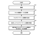
- FIG. 15 is a flow chart showing the procedure of correction processing of the interference cancellation matrix.
- a subject to be imaged is imaged (step S21), and the image data (RAW image data) is acquired (step S22).
- the acquired image data is an example of second image data.
- interference removal processing is performed on the acquired RAW image data to generate a multispectral image (step S23).
- the generated multispectral image is an example of third image data.
- the spectral characteristics of the subject are estimated using the generated multispectral image (step S24).
- the estimated spectral characteristic of the subject is an example of the feature quantity.
- the inclination of the spectral characteristics of the subject within the transmission wavelength range of each bandpass filter is estimated (step S25).
- the estimated tilt is an example of information.
- the amount of interference (crosstalk amount) in the actual environment is calculated (step S26).
- the interference matrix Ar in the real environment is obtained.
- the crosstalk matrix B is calculated based on the obtained interference matrix Ar in the real environment and the interference cancellation matrix As ⁇ 1 obtained in the specific environment (step S27).
- an inverse matrix B ⁇ 1 of the calculated crosstalk matrix B is calculated (step S28).
- the calculated inverse matrix B ⁇ 1 becomes correction data.
- the calculated inverse matrix B ⁇ 1 is used to correct the interference elimination matrix As ⁇ 1 obtained in the specific environment (step S28). Specifically, the calculated inverse matrix B ⁇ 1 is corrected by applying the interference cancellation matrix As ⁇ 1 obtained in the specific environment.
- each element of the interference cancellation matrix As ⁇ 1 obtained in the specific environment is an example of parameters used for interference cancellation processing.
- FIG. 16 is a flow chart showing the procedure of the process of generating a multispectral image.
- Image data (RAW image data) of the subject is acquired by imaging (step S32).
- interference removal processing is performed on the acquired RAW image data to generate a multispectral image (step S33).
- the interference elimination process is performed using the corrected interference elimination matrix.
- correct multispectral images are generated.
- the generated multispectral image is output to the output device 316 and/or recorded in the auxiliary storage device 314 (step S34).
- a correct multispectral image can be acquired by imaging in a real environment. That is, a high-quality multispectral image can be generated.
- the lens device when capturing a multispectral image of three wavelengths, the lens device is provided with three bandpass filters.
- one pixel block of the image sensor is composed of three pixels (for example, R pixel, G pixel and B pixel).
- the interference cancellation matrix is composed of a matrix of 3 rows and 3 columns.
- the interference cancellation matrix As ⁇ 1 obtained in the specific environment is corrected.
- Interference elimination processing is performed on the output of the image sensor using the corrected interference elimination matrix Ar ⁇ 1 .
- the obtained values match the values of the correct multispectral image X.
- the correction data (the inverse matrix B ⁇ 1 of the crosstalk matrix B) may be stored in the auxiliary storage device 314 .
- auxiliary storage device 314 instead of storing the correction data in the auxiliary storage device 314, it is also possible to configure the auxiliary storage device 314 to store the corrected interference cancellation matrix.
- a correct multispectral image is acquired by correcting image data (RAW image data) obtained by imaging.
- FIG. 17 is a block diagram of main functions realized by the image data processing device.
- the image data processing apparatus 300 of the present embodiment includes an image data acquisition unit 320, an image generation unit 321, an output control unit 324, a recording control unit 325, a RAW image correction unit 327, and a RAW correction data generation unit. It has the function of the part 328 . Each function is realized by the CPU 311 executing a predetermined program (image data processing program).
- the main difference from the image data processing apparatus 300 of the first and second embodiments is that it has a RAW image correction section 327 and a RAW correction data generation section 328 .
- a RAW image correction unit 327 performs processing for correcting the image data (RAW image data) acquired by the image data acquisition unit 320 .
- the RAW correction data generation unit 328 performs processing for generating correction data used by the RAW image correction unit 327 .
- the RAW correction data generation unit 328 generates C ⁇ as correction data.
- the RAW image data Y after correction is image data from which a correct multispectral image can be obtained when an interference removal matrix is performed using an interference removal matrix obtained in a specific environment.
- the correction data C ⁇ is obtained using the gradient of the spectral characteristics of the subject within the transmission wavelength range of each bandpass filter. Specifically, it is required as follows.
- hi( ⁇ ) be the spectral sensitivity of the i-th pixel that constitutes the pixel block of the image sensor.
- gj( ⁇ ) be the transmission characteristic of the j-th bandpass filter provided in the lens device.
- Cij ⁇ hi( ⁇ )gj( ⁇ )( ⁇ j)d ⁇
- ⁇ is the wavelength
- ⁇ j is the center wavelength of the transmission wavelength range of the j-th bandpass filter.
- ⁇ be a vector that arranges the gradients of the spectral characteristics of the subject within the transmission wavelength range of each bandpass filter.
- Corrected data C ⁇ is obtained by multiplying the matrix C by the vector ⁇ .
- FIG. 18 and 19 are diagrams showing a specific example of a method for calculating the elements Cij of the matrix C.
- FIG. 18 and 19 are diagrams showing a specific example of a method for calculating the elements Cij of the matrix C.
- Information on the spectral sensitivity hi( ⁇ ) of each pixel and information on the transmission characteristics gj( ⁇ ) of each bandpass filter are stored in the auxiliary storage device 314 in advance.
- the RAW correction data generation unit 328 estimates the inclination of the spectral characteristics of the subject within the transmission wavelength range of each bandpass filter from the multispectral image obtained by imaging. Then, the correction data C ⁇ is calculated from the estimated inclination, the information of the spectral sensitivity hi( ⁇ ) of each pixel, and the information of the transmission characteristic gj( ⁇ ) of each bandpass filter.
- the correction data C ⁇ is an example of first data.
- the image generation unit 321 performs interference elimination processing on the corrected RAW image data using the interference elimination matrix obtained in the specific environment, and generates a multispectral image.
- FIG. 20 is a flow chart showing the procedure of correction data generation processing.
- an image of a subject to be imaged is captured (step S41), and its image data (RAW image data) is acquired (step S42).
- interference removal processing is performed on the acquired RAW image data to generate a multispectral image (step S43).
- the spectral characteristics of the subject are estimated using the generated multispectral image (step S44).
- step S45 based on the estimated spectral characteristics of the subject, the inclination of the spectral characteristics of the subject within the transmission wavelength range of each bandpass filter is estimated (step S45).
- Correction data C ⁇ is generated from the estimated tilt, information on the spectral sensitivity hi( ⁇ ) of each pixel, and information on the transmission characteristic gj( ⁇ ) of each bandpass filter. Specifically, Cij is calculated and the matrix C is generated based on the information of the spectral sensitivity hi( ⁇ ) of each pixel and the information of the transmission characteristic gj( ⁇ ) of each bandpass filter. Also, a vector ⁇ is generated from the estimated inclination. The generated vector ⁇ is multiplied by the matrix C to generate correction data C ⁇ .
- FIG. 21 is a flow chart showing the procedure of the process of generating a multispectral image.
- the subject is imaged in the real environment (step S51).
- Image data (RAW image data) of the subject is acquired by imaging (step S52).
- the acquired image data (RAW image data) is an example of second image data.
- interference removal processing is performed on the corrected RAW image data to generate a multispectral image (step S54).
- the interference elimination process performed here is performed using an interference elimination matrix obtained in a specific environment. However, since the RAW image data has been corrected, a correct multispectral image is obtained.
- the generated multispectral image is output to the output device 316 and/or recorded in the auxiliary storage device 314 (step S55).
- a correct multispectral image can be acquired by imaging in a real environment. That is, a high-quality multispectral image can be generated.
- inclination information may be obtained in advance for a plurality of subjects and stored in the auxiliary storage device 314 or the like.
- a polarization method is a multispectral camera system that uses polarized light.
- a polarizing filter is mounted on the lens device and a polarizer is mounted on the image sensor.
- a polarizer is another example of an optical filter.
- a polarizing filter of the lens arrangement is provided at each opening of the filter unit.
- a polarizer of the image sensor is provided for each pixel.
- the crosstalk cancellation matrix is set in consideration of crosstalk due to polarization.
- the polarized light multispectral camera system itself a detailed description thereof is omitted (see, for example, International Publication No. 2020/075523, International Publication No. 2020/250773, etc.).
- the polarization method also includes the polarization color method.
- the polarization color method is one of polarization type multispectral camera systems, and an image sensor is equipped with a polarizer and a color filter.
- the color filters mounted on the image sensor include filters that transmit light outside the visible light range.
- a filter that transmits an infrared region is also included.
- the pixel block is appropriately set depending on the color filter arrangement of the image sensor to be used. For example, in a Bayer array color image sensor, an R pixel, a Gr pixel adjacent to the R pixel (G pixel on the same row as the R pixel), a B pixel, and a Gb pixel adjacent to the B pixel (G pixel on the same row as the B pixel). A set of pixels) constitutes one pixel block.
- a multispectral image can be generated using the outputs of three pixels, R pixels, B pixels, and Gr pixels (or Gb pixels).
- the multispectral camera can also be configured so that the lens device can be exchanged with respect to the camera body.
- the lens device can be configured so that the filter unit can be replaced. Also, it is possible to adopt a configuration in which the band-pass filters attached to the respective openings of the filter unit can be replaced. This allows the generation of multispectral images of any combination of wavelengths.
- the band-pass filter attached to each opening of the filter unit can be replaced, it is not necessary to use all the openings.
- one aperture can be used with light shielding when capturing a multispectral image of three wavelengths.
- the multispectral camera and the image data processing device are configured separately, but the camera body of the multispectral camera may have the function of the image data processing device.
- processors are general-purpose processors that run programs and function as various processing units, such as CPUs and/or GPUs (Graphic Processing Units) and FPGAs (Field Programmable Gate Arrays).
- Programmable Logic Device PLD
- ASIC Application Specific Integrated Circuit
- a dedicated electric circuit which is a processor with a circuit configuration specially designed to execute specific processing, etc. included.
- a program is synonymous with software.
- a single processing unit may be composed of one of these various processors, or may be composed of two or more processors of the same type or different types.
- one processing unit may be composed of a plurality of FPGAs or a combination of a CPU and an FPGA.
- a plurality of processing units may be configured by one processor.
- a single processor is configured with a combination of one or more CPUs and software, as typified by computers used for clients and servers. , in which the processor functions as a plurality of processing units.
- SoC System on Chip
- multispectral camera system 10 multispectral camera 100 lens device 110A lens group 110B lens group 120 filter unit 122 filter frame 122A opening (first opening) 122B opening (second opening) 122C opening (third opening) 123A bandpass filter (first bandpass filter) 123B bandpass filter (second bandpass filter) 123C bandpass filter (third bandpass filter) 200 camera body 210 image sensor 300 image data processing device 311 CPU 312 ROMs 313 RAM 314 auxiliary storage device 315 input device 316 output device 317 input/output interface 320 image data acquisition unit 321 image generation unit 322 image correction unit 323 correction data generation unit 323A spectral characteristic estimation unit 323B tilt estimation unit 323C interference amount calculation unit 323D correction data calculation Unit 324 Output control unit 325 Recording control unit 326 Parameter correction unit 327 RAW image correction unit 328 RAW correction data generation unit S1-S8 Correction data generation processing procedures S11-S15 Multispectral image generation processing procedures S21-S28 Interference removal Matrix correction processing procedures S31
Landscapes
- Engineering & Computer Science (AREA)
- Multimedia (AREA)
- Signal Processing (AREA)
- Physics & Mathematics (AREA)
- Spectroscopy & Molecular Physics (AREA)
- General Physics & Mathematics (AREA)
- Color Television Image Signal Generators (AREA)
Priority Applications (3)
| Application Number | Priority Date | Filing Date | Title |
|---|---|---|---|
| CN202280063696.5A CN117981337A (zh) | 2021-09-29 | 2022-08-19 | 图像数据处理装置及方法 |
| JP2023550447A JPWO2023053766A1 (https=) | 2021-09-29 | 2022-08-19 | |
| US18/616,213 US12615443B2 (en) | 2021-09-29 | 2024-03-26 | Image data processing device and image data processing method |
Applications Claiming Priority (2)
| Application Number | Priority Date | Filing Date | Title |
|---|---|---|---|
| JP2021159738 | 2021-09-29 | ||
| JP2021-159738 | 2021-09-29 |
Related Child Applications (1)
| Application Number | Title | Priority Date | Filing Date |
|---|---|---|---|
| US18/616,213 Continuation US12615443B2 (en) | 2021-09-29 | 2024-03-26 | Image data processing device and image data processing method |
Publications (1)
| Publication Number | Publication Date |
|---|---|
| WO2023053766A1 true WO2023053766A1 (ja) | 2023-04-06 |
Family
ID=85782320
Family Applications (1)
| Application Number | Title | Priority Date | Filing Date |
|---|---|---|---|
| PCT/JP2022/031317 Ceased WO2023053766A1 (ja) | 2021-09-29 | 2022-08-19 | 画像データ処理装置及び方法 |
Country Status (4)
| Country | Link |
|---|---|
| US (1) | US12615443B2 (https=) |
| JP (1) | JPWO2023053766A1 (https=) |
| CN (1) | CN117981337A (https=) |
| WO (1) | WO2023053766A1 (https=) |
Citations (3)
| Publication number | Priority date | Publication date | Assignee | Title |
|---|---|---|---|---|
| JP2017003495A (ja) * | 2015-06-12 | 2017-01-05 | 株式会社リコー | 情報処理装置、情報処理プログラム、および情報処理システム |
| WO2021085367A1 (ja) * | 2019-10-30 | 2021-05-06 | 富士フイルム株式会社 | 光学素子、光学装置、及び撮像装置 |
| WO2021153473A1 (ja) * | 2020-01-31 | 2021-08-05 | 富士フイルム株式会社 | レンズ装置、撮像装置、光学部材、撮像方法、及び撮像プログラム |
Family Cites Families (5)
| Publication number | Priority date | Publication date | Assignee | Title |
|---|---|---|---|---|
| US9372118B1 (en) * | 2011-03-07 | 2016-06-21 | Fluxdata, Inc. | Apparatus and method for multispectral based detection |
| WO2014110027A1 (en) * | 2013-01-10 | 2014-07-17 | Caliper Life Sciences, Inc. | Multispectral imaging system and methods |
| JP6908793B2 (ja) | 2018-10-09 | 2021-07-28 | 富士フイルム株式会社 | 撮像装置 |
| EP4314739A4 (en) * | 2021-03-30 | 2025-02-19 | Spectral MD, Inc. | SYSTEM AND METHOD FOR MULTISPECTRAL IMAGING WITH HIGH-PRECISION SNAPSHOT BASED ON MULTIPLEXED ILLUMINATION |
| US12047692B1 (en) * | 2021-11-18 | 2024-07-23 | Transformative Optics Corporation | Image sensor for improved optical imaging |
-
2022
- 2022-08-19 WO PCT/JP2022/031317 patent/WO2023053766A1/ja not_active Ceased
- 2022-08-19 JP JP2023550447A patent/JPWO2023053766A1/ja active Pending
- 2022-08-19 CN CN202280063696.5A patent/CN117981337A/zh active Pending
-
2024
- 2024-03-26 US US18/616,213 patent/US12615443B2/en active Active
Patent Citations (3)
| Publication number | Priority date | Publication date | Assignee | Title |
|---|---|---|---|---|
| JP2017003495A (ja) * | 2015-06-12 | 2017-01-05 | 株式会社リコー | 情報処理装置、情報処理プログラム、および情報処理システム |
| WO2021085367A1 (ja) * | 2019-10-30 | 2021-05-06 | 富士フイルム株式会社 | 光学素子、光学装置、及び撮像装置 |
| WO2021153473A1 (ja) * | 2020-01-31 | 2021-08-05 | 富士フイルム株式会社 | レンズ装置、撮像装置、光学部材、撮像方法、及び撮像プログラム |
Also Published As
| Publication number | Publication date |
|---|---|
| CN117981337A (zh) | 2024-05-03 |
| US12615443B2 (en) | 2026-04-28 |
| US20240236508A1 (en) | 2024-07-11 |
| JPWO2023053766A1 (https=) | 2023-04-06 |
Similar Documents
| Publication | Publication Date | Title |
|---|---|---|
| JP6064290B2 (ja) | 撮像装置、分光システム、および分光方法 | |
| JP5786149B2 (ja) | 汎用的に詰め合わせたピクセル配列のカメラシステムおよび方法 | |
| US7876363B2 (en) | Methods, systems and apparatuses for high-quality green imbalance compensation in images | |
| US20220385863A1 (en) | Imaging apparatus and method | |
| US20220078319A1 (en) | Imaging apparatus | |
| JP5943393B2 (ja) | 撮像装置 | |
| JP2018538753A (ja) | 単一のマトリクスセンサによって可視および近赤外画像を取得するためのシステムおよび方法 | |
| US9911060B2 (en) | Image processing apparatus, image processing method, and storage medium for reducing color noise in an image | |
| US9843782B2 (en) | Interpolation device, storage medium, and method with multi-band color filter and noise reduced reference image | |
| US20240371052A1 (en) | Information processing apparatus, information processing method, and program | |
| US20230419458A1 (en) | Image data processing device, image data processing method, image data processing program, and imaging system | |
| JP5718138B2 (ja) | 画像信号処理装置及びプログラム | |
| US20210142446A1 (en) | Image processing device, image processing method, and non-transitory computer-readable medium | |
| JP6708378B2 (ja) | 画像処理装置、撮像装置、画像処理方法、画像処理プログラム、および、記憶媒体 | |
| WO2023053766A1 (ja) | 画像データ処理装置及び方法 | |
| KR102710736B1 (ko) | 이미지 획득 장치의 색상 응답 특성을 산출하는 방법 | |
| US9838659B2 (en) | Image processing device and image processing method | |
| JP2013187711A (ja) | 画像処理装置、撮像装置及び画像処理方法 | |
| US20250371667A1 (en) | Frequency based color moiré pattern detection | |
| US11982899B2 (en) | Image processing device, imaging device, image processing method, and image processing program | |
| WO2020213418A1 (ja) | 撮像装置、信号処理装置、信号処理方法及び信号処理プログラム | |
| US11837617B2 (en) | Under-display camera system and operating method thereof | |
| WO2013111824A1 (ja) | 画像処理装置、撮像装置及び画像処理方法 | |
| WO2023188512A1 (ja) | 情報処理装置、情報処理方法、及びプログラム | |
| US20210112223A1 (en) | Image processing device, image processing system, image processing method, and program recording medium |
Legal Events
| Date | Code | Title | Description |
|---|---|---|---|
| 121 | Ep: the epo has been informed by wipo that ep was designated in this application |
Ref document number: 22873967 Country of ref document: EP Kind code of ref document: A1 |
|
| WWE | Wipo information: entry into national phase |
Ref document number: 202280063696.5 Country of ref document: CN |
|
| WWE | Wipo information: entry into national phase |
Ref document number: 2023550447 Country of ref document: JP |
|
| NENP | Non-entry into the national phase |
Ref country code: DE |
|
| 122 | Ep: pct application non-entry in european phase |
Ref document number: 22873967 Country of ref document: EP Kind code of ref document: A1 |