WO2023053643A1 - 光学シート積層体、バックライトユニット、液晶表示装置、情報機器、及びバックライトユニットの製造方法 - Google Patents
光学シート積層体、バックライトユニット、液晶表示装置、情報機器、及びバックライトユニットの製造方法 Download PDFInfo
- Publication number
- WO2023053643A1 WO2023053643A1 PCT/JP2022/025924 JP2022025924W WO2023053643A1 WO 2023053643 A1 WO2023053643 A1 WO 2023053643A1 JP 2022025924 W JP2022025924 W JP 2022025924W WO 2023053643 A1 WO2023053643 A1 WO 2023053643A1
- Authority
- WO
- WIPO (PCT)
- Prior art keywords
- sheet
- prism
- diffusion
- sheets
- backlight unit
- Prior art date
Links
- 230000003287 optical effect Effects 0.000 title claims abstract description 70
- 239000004973 liquid crystal related substance Substances 0.000 title claims description 48
- 238000004519 manufacturing process Methods 0.000 title claims description 16
- 238000009792 diffusion process Methods 0.000 claims abstract description 177
- 239000011159 matrix material Substances 0.000 claims abstract description 16
- 238000000034 method Methods 0.000 claims description 21
- 238000011156 evaluation Methods 0.000 claims description 13
- 239000010410 layer Substances 0.000 description 52
- 239000000758 substrate Substances 0.000 description 25
- 238000006243 chemical reaction Methods 0.000 description 19
- 239000011347 resin Substances 0.000 description 19
- 229920005989 resin Polymers 0.000 description 19
- 239000000463 material Substances 0.000 description 15
- 238000009826 distribution Methods 0.000 description 7
- 238000011077 uniformity evaluation Methods 0.000 description 7
- 238000010586 diagram Methods 0.000 description 6
- 238000005259 measurement Methods 0.000 description 5
- 239000004925 Acrylic resin Substances 0.000 description 4
- 229920000178 Acrylic resin Polymers 0.000 description 4
- 239000011521 glass Substances 0.000 description 4
- 239000002245 particle Substances 0.000 description 4
- 239000004033 plastic Substances 0.000 description 4
- 229920003023 plastic Polymers 0.000 description 4
- 239000004417 polycarbonate Substances 0.000 description 4
- 229920000515 polycarbonate Polymers 0.000 description 4
- -1 polyethylene terephthalate Polymers 0.000 description 4
- 229920000139 polyethylene terephthalate Polymers 0.000 description 4
- 239000005020 polyethylene terephthalate Substances 0.000 description 4
- NIXOWILDQLNWCW-UHFFFAOYSA-M Acrylate Chemical compound [O-]C(=O)C=C NIXOWILDQLNWCW-UHFFFAOYSA-M 0.000 description 3
- 229920002799 BoPET Polymers 0.000 description 3
- 239000000654 additive Substances 0.000 description 3
- 239000003795 chemical substances by application Substances 0.000 description 3
- 230000000694 effects Effects 0.000 description 3
- 238000001125 extrusion Methods 0.000 description 3
- 239000002184 metal Substances 0.000 description 3
- 239000002096 quantum dot Substances 0.000 description 3
- 238000012546 transfer Methods 0.000 description 3
- 239000004793 Polystyrene Substances 0.000 description 2
- 230000007423 decrease Effects 0.000 description 2
- 239000011229 interlayer Substances 0.000 description 2
- 238000003475 lamination Methods 0.000 description 2
- 229920002223 polystyrene Polymers 0.000 description 2
- 238000004088 simulation Methods 0.000 description 2
- 238000002834 transmittance Methods 0.000 description 2
- 239000004988 Nematic liquid crystal Substances 0.000 description 1
- 239000004952 Polyamide Substances 0.000 description 1
- 239000004642 Polyimide Substances 0.000 description 1
- 238000010521 absorption reaction Methods 0.000 description 1
- NIXOWILDQLNWCW-UHFFFAOYSA-N acrylic acid group Chemical group C(C=C)(=O)O NIXOWILDQLNWCW-UHFFFAOYSA-N 0.000 description 1
- 229920002301 cellulose acetate Polymers 0.000 description 1
- 229920006026 co-polymeric resin Polymers 0.000 description 1
- 230000001771 impaired effect Effects 0.000 description 1
- 238000009776 industrial production Methods 0.000 description 1
- 238000001746 injection moulding Methods 0.000 description 1
- 230000001678 irradiating effect Effects 0.000 description 1
- 238000010030 laminating Methods 0.000 description 1
- ADFPJHOAARPYLP-UHFFFAOYSA-N methyl 2-methylprop-2-enoate;styrene Chemical compound COC(=O)C(C)=C.C=CC1=CC=CC=C1 ADFPJHOAARPYLP-UHFFFAOYSA-N 0.000 description 1
- 238000012986 modification Methods 0.000 description 1
- 230000004048 modification Effects 0.000 description 1
- 239000011146 organic particle Substances 0.000 description 1
- 230000010287 polarization Effects 0.000 description 1
- 229920003207 poly(ethylene-2,6-naphthalate) Polymers 0.000 description 1
- 229920002647 polyamide Polymers 0.000 description 1
- 239000011112 polyethylene naphthalate Substances 0.000 description 1
- 229920001721 polyimide Polymers 0.000 description 1
- 238000012545 processing Methods 0.000 description 1
- 239000011241 protective layer Substances 0.000 description 1
- 239000012508 resin bead Substances 0.000 description 1
- 239000003566 sealing material Substances 0.000 description 1
- 239000002356 single layer Substances 0.000 description 1
- 229920003002 synthetic resin Polymers 0.000 description 1
- 239000000057 synthetic resin Substances 0.000 description 1
Images


Classifications
-
- G—PHYSICS
- G02—OPTICS
- G02F—OPTICAL DEVICES OR ARRANGEMENTS FOR THE CONTROL OF LIGHT BY MODIFICATION OF THE OPTICAL PROPERTIES OF THE MEDIA OF THE ELEMENTS INVOLVED THEREIN; NON-LINEAR OPTICS; FREQUENCY-CHANGING OF LIGHT; OPTICAL LOGIC ELEMENTS; OPTICAL ANALOGUE/DIGITAL CONVERTERS
- G02F1/00—Devices or arrangements for the control of the intensity, colour, phase, polarisation or direction of light arriving from an independent light source, e.g. switching, gating or modulating; Non-linear optics
- G02F1/01—Devices or arrangements for the control of the intensity, colour, phase, polarisation or direction of light arriving from an independent light source, e.g. switching, gating or modulating; Non-linear optics for the control of the intensity, phase, polarisation or colour
- G02F1/13—Devices or arrangements for the control of the intensity, colour, phase, polarisation or direction of light arriving from an independent light source, e.g. switching, gating or modulating; Non-linear optics for the control of the intensity, phase, polarisation or colour based on liquid crystals, e.g. single liquid crystal display cells
- G02F1/133—Constructional arrangements; Operation of liquid crystal cells; Circuit arrangements
- G02F1/1333—Constructional arrangements; Manufacturing methods
- G02F1/1335—Structural association of cells with optical devices, e.g. polarisers or reflectors
- G02F1/1336—Illuminating devices
- G02F1/133602—Direct backlight
- G02F1/133606—Direct backlight including a specially adapted diffusing, scattering or light controlling members
-
- F—MECHANICAL ENGINEERING; LIGHTING; HEATING; WEAPONS; BLASTING
- F21—LIGHTING
- F21S—NON-PORTABLE LIGHTING DEVICES; SYSTEMS THEREOF; VEHICLE LIGHTING DEVICES SPECIALLY ADAPTED FOR VEHICLE EXTERIORS
- F21S2/00—Systems of lighting devices, not provided for in main groups F21S4/00 - F21S10/00 or F21S19/00, e.g. of modular construction
-
- G—PHYSICS
- G02—OPTICS
- G02B—OPTICAL ELEMENTS, SYSTEMS OR APPARATUS
- G02B5/00—Optical elements other than lenses
- G02B5/02—Diffusing elements; Afocal elements
-
- G—PHYSICS
- G02—OPTICS
- G02B—OPTICAL ELEMENTS, SYSTEMS OR APPARATUS
- G02B5/00—Optical elements other than lenses
- G02B5/04—Prisms
-
- G—PHYSICS
- G02—OPTICS
- G02F—OPTICAL DEVICES OR ARRANGEMENTS FOR THE CONTROL OF LIGHT BY MODIFICATION OF THE OPTICAL PROPERTIES OF THE MEDIA OF THE ELEMENTS INVOLVED THEREIN; NON-LINEAR OPTICS; FREQUENCY-CHANGING OF LIGHT; OPTICAL LOGIC ELEMENTS; OPTICAL ANALOGUE/DIGITAL CONVERTERS
- G02F1/00—Devices or arrangements for the control of the intensity, colour, phase, polarisation or direction of light arriving from an independent light source, e.g. switching, gating or modulating; Non-linear optics
- G02F1/01—Devices or arrangements for the control of the intensity, colour, phase, polarisation or direction of light arriving from an independent light source, e.g. switching, gating or modulating; Non-linear optics for the control of the intensity, phase, polarisation or colour
- G02F1/13—Devices or arrangements for the control of the intensity, colour, phase, polarisation or direction of light arriving from an independent light source, e.g. switching, gating or modulating; Non-linear optics for the control of the intensity, phase, polarisation or colour based on liquid crystals, e.g. single liquid crystal display cells
- G02F1/133—Constructional arrangements; Operation of liquid crystal cells; Circuit arrangements
- G02F1/1333—Constructional arrangements; Manufacturing methods
- G02F1/1335—Structural association of cells with optical devices, e.g. polarisers or reflectors
- G02F1/1336—Illuminating devices
- G02F1/133602—Direct backlight
- G02F1/133611—Direct backlight including means for improving the brightness uniformity
-
- F—MECHANICAL ENGINEERING; LIGHTING; HEATING; WEAPONS; BLASTING
- F21—LIGHTING
- F21Y—INDEXING SCHEME ASSOCIATED WITH SUBCLASSES F21K, F21L, F21S and F21V, RELATING TO THE FORM OR THE KIND OF THE LIGHT SOURCES OR OF THE COLOUR OF THE LIGHT EMITTED
- F21Y2115/00—Light-generating elements of semiconductor light sources
- F21Y2115/10—Light-emitting diodes [LED]
-
- F—MECHANICAL ENGINEERING; LIGHTING; HEATING; WEAPONS; BLASTING
- F21—LIGHTING
- F21Y—INDEXING SCHEME ASSOCIATED WITH SUBCLASSES F21K, F21L, F21S and F21V, RELATING TO THE FORM OR THE KIND OF THE LIGHT SOURCES OR OF THE COLOUR OF THE LIGHT EMITTED
- F21Y2115/00—Light-generating elements of semiconductor light sources
- F21Y2115/30—Semiconductor lasers
Definitions
- the present disclosure relates to an optical sheet laminate, a backlight unit, a liquid crystal display device, information equipment, and a method for manufacturing a backlight unit.
- liquid crystal display devices (hereinafter also referred to as liquid crystal displays) have been widely used as display devices for various information devices such as smartphones and tablet terminals.
- Backlights for liquid crystal displays are required to have high brightness and high contrast, so a direct type system in which the light source is arranged on the back surface of the liquid crystal panel has become mainstream.
- an optical system such as a diffusion sheet or prism sheet is required to diffuse the light from the light source such as LED (Light Emitting Diode) and improve the uniformity of brightness and chromaticity over the entire screen.
- a sheet is used (see, for example, Patent Document 1).
- a diffusion sheet in which, for example, inverted pyramid-shaped recesses are arranged two-dimensionally is used, and a prism is usually placed on the upper side (display screen) of the diffusion sheet. Two prism sheets whose ridge lines are perpendicular to each other are arranged.
- Portable information terminals such as laptops and tablets, which are used while being carried around, require a sheet laminated structure that is thin and has high brightness uniformity. Therefore, depending on the product, the conventional sheet lamination structure may not provide sufficient luminance uniformity.
- An object of the present disclosure is to provide an optical sheet laminate capable of improving luminance uniformity of a backlight unit.
- an optical sheet laminate according to the present disclosure is an optical sheet laminate to be incorporated in a backlight unit, wherein a plurality of substantially inverted quadrangular pyramid-shaped recesses are formed in a two-dimensional matrix on at least one surface. and a pair of prism sheets whose prism stretching directions are orthogonal to each other, wherein the plurality of recesses in the first diffusion sheet closest to the pair of prism sheets among the plurality of diffusion sheets
- the first arrangement direction intersects the prism extension direction at an angle of 0° or more and 20° or less, or an angle of 70° or more and 90° or less.
- a backlight unit is obtained by stacking a plurality of diffusion sheets (hereinafter sometimes referred to as pyramid sheets) each having a plurality of substantially inverted quadrangular pyramid-shaped depressions on one surface.
- brightness uniformity can be improved.
- the concave arrangement direction of the first diffusion sheet closest to the prism sheet intersects the prism stretching direction at an angle of 0° or more and 20° or less or 70° or more and 90° or less, the same light source, the same power, and the same optical
- the brightness uniformity of the backlight unit is further improved compared to other angles of intersection in the sheet stack configuration.
- the second arrangement direction of the plurality of concave portions in at least one second diffusion sheet among the plurality of diffusion sheets excluding the first diffusion sheet is substantially the same as the first arrangement direction. may be substantially the same. By doing so, it is possible to further improve the luminance uniformity of the backlight unit according to conditions such as the arrangement of the point light sources and the positional relationship between the optical sheets.
- substantially the same direction means that the angle difference between the two directions is 5° or less, preferably 3° or less, more preferably 1° or less.
- the second arrangement direction of the plurality of recesses in at least one second diffusion sheet among the plurality of diffusion sheets excluding the first diffusion sheet is different from the first arrangement direction.
- different directions mean that the angle difference between the two directions is more than 5°, preferably 10° or more.
- a backlight unit is a backlight unit that is incorporated in a liquid crystal display device and guides light emitted from a light source to a display screen side, and between the display screen and the light source, wherein the plurality of diffusion sheets are arranged between the light source and the pair of prism sheets.
- the backlight unit according to the present disclosure since it includes the above-described optical sheet laminate according to the present disclosure, luminance uniformity can be improved.
- the light source may be arranged on a reflective sheet provided on the opposite side of the display screen when viewed from the plurality of diffusion sheets. In this way, light is further diffused by multiple reflections between the diffuser sheet and the reflective sheet, thereby further improving luminance uniformity.
- the distance between the light source and the plurality of diffusion sheets may be 5 mm or less, preferably 2.5 mm or less, more preferably 1 mm or less. By doing so, the backlight unit can be miniaturized.
- a liquid crystal display device includes the aforementioned backlight unit according to the present disclosure and a liquid crystal display panel.
- liquid crystal display device since the backlight unit according to the present disclosure described above is provided, luminance uniformity can be improved.
- the information equipment according to the present disclosure includes the above-described liquid crystal display device according to the present disclosure.
- the liquid crystal display device according to the present disclosure since the liquid crystal display device according to the present disclosure is provided, luminance uniformity can be improved.
- a method for manufacturing a backlight unit according to the present disclosure is a method for manufacturing a backlight unit that is incorporated in a liquid crystal display device and guides light emitted from a light source to a display screen side.
- the method for manufacturing a backlight unit in the step of arranging a plurality of diffusion sheets, the result of evaluating the luminance uniformity while changing the intersection angle between the arrangement direction of the recesses in each diffusion sheet and the prism stretching direction. , the arrangement direction of the concave portions in each diffusion sheet is determined. Therefore, the arrangement direction of the concave portions in each diffusion sheet can be set so as to improve luminance uniformity.
- an optical sheet laminate capable of improving the brightness uniformity of the backlight unit.
- FIG. 1 is a cross-sectional view of a liquid crystal display device including a backlight unit according to an embodiment
- FIG. FIG. 4 is a cross-sectional view of a backlight unit incorporating the optical sheet laminate according to the embodiment
- 4 is a cross-sectional view of a diffusion sheet included in the optical sheet laminate according to the embodiment
- FIG. 4 is a perspective view of a diffusion sheet included in the optical sheet laminate according to the embodiment
- FIG. 4 is a diagram showing an example of the relationship between the arrangement direction of concave portions of a diffusion sheet and the extending direction of prisms of a prism sheet in an optical sheet laminate according to an embodiment
- 5 is a diagram showing the relationship for explaining the arrangement angles of the diffusion sheet (pyramid sheet) and the prism sheet in the optical sheet laminate according to Example 1.
- FIG. FIG. 10 is a diagram showing changes in luminance uniformity when changing the difference in arrangement angle between the diffusion sheet (pyramid sheet) and the upper prism sheet in the optical sheet laminate according to Example 1
- FIG. 10 is a diagram showing changes in luminance when the difference in arrangement angle between a diffusion sheet (pyramid sheet) and an upper prism sheet is changed in an optical sheet laminate according to a reference example
- FIG. 10 is a diagram showing changes in luminance uniformity when the arrangement angle of the upper prism sheet is changed in the optical sheet laminate according to Example 4;
- FIG. 10 is a diagram showing changes in luminance when the arrangement angle of the upper prism sheet is changed in the optical sheet laminate according to Example 4;
- the liquid crystal display device 50 includes a liquid crystal display panel 5, a first polarizing plate 6 attached to the lower surface of the liquid crystal display panel 5, and a second polarizing plate attached to the upper surface of the liquid crystal display panel 5. 7 and a backlight unit 40 provided on the back side of the liquid crystal display panel 5 with the first polarizing plate 6 interposed therebetween.
- the liquid crystal display panel 5 includes a TFT substrate 1 and a CF substrate 2 facing each other, a liquid crystal layer 3 provided between the TFT substrate 1 and the CF substrate 2, and the TFT substrate 1 and the CF substrate 2.
- a frame-shaped sealing material (not shown) is provided to seal the liquid crystal layer 3 between them.
- the shape of the display screen 50a of the liquid crystal display device 50 viewed from the front (upper side in FIG. 1) is, in principle, rectangular or square, but is not limited thereto, and may be a rectangular shape with rounded corners, an elliptical shape, a circular shape, or the like. Any shape such as a trapezoid or an automobile instrument panel (instrument panel) may be used.
- liquid crystal display device 50 in each sub-pixel corresponding to each pixel electrode, a voltage of a predetermined magnitude is applied to the liquid crystal layer 3 to change the alignment state of the liquid crystal layer 3 . Thereby, the transmittance of the light incident from the backlight unit 40 through the first polarizing plate 6 is adjusted. The light whose transmittance has been adjusted is emitted through the second polarizing plate 7 to display an image.
- the liquid crystal display device 50 of the present embodiment can be used for various information devices (for example, in-vehicle devices such as car navigation systems, personal computers, mobile phones, portable information terminals such as notebook computers and tablets, portable game machines, copiers, ticket vending machines, It is used as a display device incorporated in an automatic teller machine, etc.).
- information devices for example, in-vehicle devices such as car navigation systems, personal computers, mobile phones, portable information terminals such as notebook computers and tablets, portable game machines, copiers, ticket vending machines, It is used as a display device incorporated in an automatic teller machine, etc.).
- the TFT substrate 1 includes, for example, a plurality of TFTs provided in a matrix on a glass substrate, an interlayer insulating film provided so as to cover each TFT, and a plurality of TFTs provided in a matrix on the interlayer insulating film. and an alignment film provided to cover each pixel electrode.
- the CF substrate 2 includes, for example, a black matrix provided in a grid pattern on a glass substrate, a color filter including a red layer, a green layer, and a blue layer provided between the grids of the black matrix, and a black matrix and a color filter.
- a common electrode is provided to cover the filter, and an alignment film is provided to cover the common electrode.
- the liquid crystal layer 3 is made of a nematic liquid crystal material or the like containing liquid crystal molecules having electro-optical properties.
- the first polarizing plate 6 and the second polarizing plate 7 each include, for example, a polarizer layer having a unidirectional polarization axis and a pair of protective layers provided to sandwich the polarizer layer.
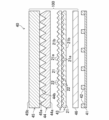
- the backlight unit 40 includes a reflective sheet 41, a plurality of light sources 42 two-dimensionally arranged on the reflective sheet 41, and an optical sheet laminate provided above the plurality of light sources 42. 100.
- the optical sheet laminate 100 has a diffusion sheet 43 arranged on the light source 42 side, and a pair of prism sheets 44 and 45 provided above the diffusion sheet 43 (on the display screen 50a side).
- the optical sheet laminate 100 has a color conversion sheet 46 between the light source 42 and the diffusion sheet 43 .
- Each sheet constituting the optical sheet laminate 100 may be in the form of a film or a plate.
- two diffusion sheets 43 having the same structure are laminated and provided in the backlight unit 40 .
- the diffusion sheet 43 may be used by one sheet, or may be used by laminating three or more sheets.
- a single diffuser sheet 43 may be used in the backlight unit 40.
- the pair of prism sheets 44 and 45 may be a lower prism sheet 44 and an upper prism sheet 45 whose prism stretching directions (directions in which prism ridgelines extend) are orthogonal to each other.
- the color conversion sheet 46 may be arranged between the diffusion sheet 43 and the pair of prism sheets 44 and 45 .
- the reflective sheet 41 is composed of, for example, a white film made of polyethylene terephthalate resin, a silver-deposited film, or the like.
- the light source 42 may be, for example, a blue light source that emits light with x ⁇ 0.24 and y ⁇ 0.18 in CIE 1931 chromaticity coordinates.
- the type of the light source 42 is not particularly limited, it may be, for example, an LED element, a laser element, or the like, and an LED element may be used from the viewpoint of cost, productivity, and the like.
- a lens may be attached to the LED element to adjust the light output angle characteristics of the LED.
- the LED element may have a rectangular shape when viewed from above, in which case the length of one side is 50 ⁇ m or more (preferably 100 ⁇ m or more) and 1 mm. It may be below.
- the LED chips may be two-dimensionally arranged on the reflective sheet 41 at regular intervals.
- the center-to-center distance between two adjacent chips may be 0.5 mm or more (preferably 2 mm or more) and 20 mm or less.
- a white light source may be used as the light source 42 instead of the blue light source.
- the white light source is composed of, for example, an LED element whose peak wavelength is in the blue region, an LED element whose peak wavelength is in the green region, and an LED element whose peak wavelength is in the red region. ⁇ 0.42, 0.18 ⁇ y ⁇ 0.48 light may be emitted.
- the color conversion sheet 46 may not be provided.
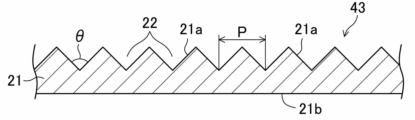
- the diffusion sheet 43 has a base material layer 21 as shown in FIGS.
- the diffusion sheet 43 (base material layer 21) has a first surface 21a serving as a light emitting surface and a second surface 21b serving as a light incident surface. That is, the diffusion sheet 43 is arranged with the second surface 21 b facing the light source 42 .
- the resin serving as the matrix of the base material layer 21 is not particularly limited as long as it is composed of a material that transmits light. Examples include acrylic, polystyrene, polycarbonate, MS (methyl methacrylate-styrene copolymer) resin, polyethylene terephthalate, Polyethylene naphthalate, cellulose acetate, polyimide, and the like may also be used.
- the base material layer 21 may contain a diffusing agent and other additives, or may contain substantially no additives.
- Additives that can be contained in the base material layer 21 are not particularly limited. It may be organic particles such as polystyrene, polyamide, and the like.
- the thickness of the diffusion sheet 43 is not particularly limited, but may be, for example, 3 mm or less (preferably 2 mm or less, more preferably 1.5 mm or less, still more preferably 1 mm or less) and 0.1 mm or more. When the thickness of the diffusion sheet 43 exceeds 3 mm, it becomes difficult to achieve a thin liquid crystal display. If the thickness of the diffusion sheet 43 is less than 0.1 mm, it becomes difficult to make the brightness uniform.
- the diffusion sheet 43 may be film-like or plate-like.
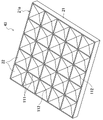
- a plurality of recesses 22 having a substantially inverted quadrangular pyramid shape are arranged in a two-dimensional matrix.
- the plurality of recesses 22 are arranged along two directions orthogonal to each other.
- Adjacent recesses 22 are separated by ridgelines 111 .
- the ridgeline 111 extends along two directions in which the recesses 22 are arranged.
- the center 112 of the recess 22 (the apex of the inverted pyramid) is the deepest part of the recess 22 .
- the recesses 22 may be provided without gaps on the first surface 21a, or may be provided at predetermined intervals. Moreover, some recesses 22 may be arranged randomly to the extent that the light diffusion effect is not impaired.
- the apex angle ⁇ of the recesses 22 may be, for example, 90°, the arrangement pitch p of the recesses 22 may be, for example, 100 ⁇ m, and the depth of the recesses 22 may be, for example, 50 ⁇ m.
- the apex angle ⁇ of the concave portion 22 is a plane (longitudinal section) perpendicular to the surface on which the diffusion sheet 43 is arranged, and is a pair of slopes that pass through the center of the concave portion 22 (apex 112 of the inverted pyramid) and face each other across the center. It is the angle formed by the cross-sectional lines of the slopes in the cross-section that appears when the cross-section is cut perpendicular to the cross-section.
- the arrangement pitch p of the recesses 22 is the distance between the centers (the apexes 112 of the inverted pyramids) of the adjacent recesses 22 (the distance along the direction parallel to the arrangement surface of the diffusion sheet 43).
- the second surface 21b of the diffusion sheet 43 may be, for example, a flat surface (mirror surface) or an embossed surface.
- the diffusion sheet 43 may have a one-layer structure of the base material layer 21 having an uneven shape (recesses 22) on the first surface 21a.
- the diffusion sheet 43 may have a two-layer structure including a substrate layer having flat surfaces on both sides and a layer having an uneven surface on one side.
- the diffusion sheet 43 may have a structure of three or more layers including a layer having unevenness on one surface.
- a method for manufacturing the diffusion sheet 43 is not particularly limited, but for example, an extrusion molding method, an injection molding method, or the like may be used.
- the procedure for manufacturing a single-layer diffusion sheet with an uneven surface using an extrusion molding method is as follows. First, pellet-shaped plastic particles to which a diffusing agent has been added (along with pellet-shaped plastic particles to which no diffusing agent has been added may be mixed) are put into a single-screw extruder, heated and melted, knead. After that, the molten resin extruded by the T-die is sandwiched between two metal rolls, cooled, transported using guide rolls, and cut into single flat plates by a sheet cutter to produce a diffusion sheet.
- the reverse shape of the roll surface is transferred to the resin, so that the desired uneven shape is formed on the surface of the diffusion sheet. It can be shaped.
- the shape transferred to the resin does not always correspond to the shape of the roll surface that is 100% transferred, the shape of the roll surface may be designed by calculating backward from the degree of transfer.
- pellet-shaped plastic particles necessary for forming each layer are put into each of two single-screw extruders. After that, the same procedure as described above is performed for each layer, and each sheet thus produced may be laminated.
- a diffusion sheet with a two-layer structure having an uneven surface may be produced as follows. First, pellet-like plastic particles necessary for forming each layer are put into each of two single-screw extruders, melted and kneaded while being heated. After that, the molten resin for each layer is put into one T-die, laminated in the T-die, and the laminated molten resin extruded by the T-die is sandwiched between two metal rolls and cooled. After that, the laminated molten resin may be conveyed using guide rolls and cut into flat plates with a sheet cutter to produce a diffusion sheet having a two-layer structure having an uneven surface.
- the diffusion sheet may be manufactured as follows by shape transfer using UV (ultraviolet). First, a roll having an inverted shape of the uneven shape to be transferred is filled with an uncured UV curable resin, and the substrate is pressed against the resin. Next, in a state in which the roll filled with the ultraviolet curable resin and the substrate are integrated, the resin is cured by irradiating ultraviolet rays. Next, the sheet on which the concavo-convex shape has been shape-transferred by the resin is separated from the roll. Finally, the sheet is again irradiated with ultraviolet rays to completely harden the resin, thereby producing a diffusion sheet having an uneven surface.
- UV ultraviolet
- the notation “substantially inverted quadrangular pyramid” in consideration of the fact that it is difficult to form a geometrically strict inverted quadrangular pyramid recess by a normal shape transfer technique, the notation “substantially inverted quadrangular pyramid” is used, but “substantially “Inverted square pyramid” shall include shapes that can be considered true or substantially inverted square pyramids. Further, the term “substantially” means that it can be approximated, and the term “substantially inverted quadrangular pyramid” means a shape that can be approximated to an inverted quadrangular pyramid. For example, an "inverted quadrangular truncated pyramid" with a flat top is also included in the “substantially inverted quadrangular pyramid” if the top area is small enough to maintain the effects of the present invention. Further, a shape that is deformed from the "inverted square pyramid” within the range of unavoidable variations in shape due to processing accuracy in industrial production is also included in the "substantially inverted square pyramid".
- the prism sheets 44 and 45 are made mainly of a transparent (for example, colorless and transparent) synthetic resin because they are required to transmit light rays.
- the prism sheets 44 and 45 may be integrally formed.
- the lower prism sheet 44 has a substrate layer 44a and a row of projections composed of a plurality of ridge prism portions 44b laminated on the surface of the substrate layer 44a.
- the upper prism sheet 45 has a substrate layer 45a and a row of projections composed of a plurality of ridge prism portions 45b laminated on the surface of the substrate layer 45a.
- the ridge prism portions 44b and 45b are laminated in stripes on the surfaces of the substrate layers 44a and 45a, respectively.
- the ridge prism portions 44b and 45b are triangular prisms whose back surfaces are in contact with the surfaces of the substrate layers 44a and 45a, respectively.
- the extension direction of the ridge prism portion 44b and the extension direction of the ridge prism portion 45b are orthogonal to each other.
- the lower limit of the thickness of the prism sheets 44 and 45 (the height from the back surface of the base material layers 44a and 45a to the vertices of the ridge prism portions 44b and 45b) is, for example, about 50 ⁇ m, more preferably about 100 ⁇ m. good.
- the upper limit of the thickness of the prism sheets 44 and 45 may be approximately 200 ⁇ m, more preferably approximately 180 ⁇ m.
- the lower limit of the pitch of the ridge prism portions 44b and 45b on the prism sheets 44 and 45 may be, for example, about 20 ⁇ m, more preferably about 25 ⁇ m.
- the upper limit of the pitch of the prismatic protrusions 44b and 45b on the prism sheets 44 and 45 may be, for example, approximately 100 ⁇ m, more preferably approximately 60 ⁇ m.
- the apex angles of the ridge prism portions 44b and 45b may be, for example, 85° or more and 95° or less.
- the lower limit of the refractive index of the ridge prism portions 44b and 45b may be, for example, 1.5, more preferably 1.55.
- the upper limit of the refractive index of the ridge prism portions 44b and 45b may be, for example, 1.7.
- Prism sheets 44 and 45 are formed by providing ridge prism portions 44b and 45b, which are shape-transferred using a UV curable acrylic resin, on substrate layers 44a and 45a made of, for example, PET (polyethylene terephthalate) film.
- substrate layers 44a and 45a made of, for example, PET (polyethylene terephthalate) film.
- the ridge prism portions 44b and 45b may be formed integrally with the base layers 44a and 45a.
- the color conversion sheet 46 is a wavelength conversion sheet that converts the light from the light source 42 into light having a peak wavelength of an arbitrary color (for example, green or red). For example, if the light source 42 is a blue light source, the color conversion sheet 46 converts blue light with a wavelength of 450 nm into green light with a wavelength of 540 nm and red light with a wavelength of 650 nm. In this case, if the light source 42 that emits blue light with a wavelength of 450 nm is used, the blue light is partially converted into green light and red light by the color conversion sheet 46, so that the light transmitted through the color conversion sheet 46 becomes white light. Become. As the color conversion sheet 46, for example, a QD (quantum dot) sheet, a fluorescent sheet, or the like may be used. If a white light source is used as the light source 42, the color conversion sheet 46 may not be provided.
- a QD (quantum dot) sheet, a fluorescent sheet, or the like may be used as the light
- a polarizing sheet may be provided above the prism sheets 44 and 45 (on the display screen 50a side).
- the polarizing sheet prevents the light emitted from the backlight unit 40 from being absorbed by the first polarizing plate 6 of the liquid crystal display device 50, thereby improving the brightness of the display screen 50a.
- the optical sheet laminate 100 of this embodiment is incorporated into the backlight unit 40 .
- the optical sheet laminate 100 includes a plurality of diffusion sheets 43 in which a plurality of substantially inverted quadrangular pyramid-shaped concave portions 22 are arranged in a two-dimensional matrix on the first surface 21a, and the elongated prism portions 44b and 45b. , the prism stretching direction) are perpendicular to each other.
- the optical sheet laminate 100 for example, as shown in FIG. intersect at an angle of 0° or more and 20° or less, or 70° or more and 90° or less.
- the projection prism portion 44b is not shown for the sake of simplicity.
- the extending direction of the prism portion 45b satisfies the crossing angle range described above
- the extending direction of the ridge prism portion 44b also satisfies the crossing angle range described above.
- the optical sheet laminate 100 of the present embodiment by stacking a plurality of diffusion sheets (hereinafter also referred to as pyramid sheets) 43 each having a plurality of recesses 22 in the shape of a substantially inverted square pyramid on one surface,
- the brightness uniformity of the backlight unit 40 can be improved.
- the recess arrangement direction of the diffusion sheet 43 closest to the prism sheets 44 and 45 intersects the prism stretching direction at an angle of 0° or more and 20° or less or 70° or more and 90° or less, the same light source, the same power,
- the luminance uniformity of the backlight unit 40 is further improved compared to the case where the same optical sheet lamination configuration is crossed at other angles.
- the arrangement direction of the recesses 22 in the diffusion sheet 43 closest to the prism sheets 44 and 45 and the arrangement direction of the recesses 22 in the other diffusion sheets 43 depend on the arrangement of the light source 42 and the optical system. Depending on conditions such as the positional relationship of the optical sheets of the sheet stack 100, they may be substantially the same or may be different. In this way, the brightness uniformity of the backlight unit 40 can be further improved according to conditions such as the arrangement of the light sources 42 and the positional relationship of the optical sheets of the optical sheet laminate 100 .
- substantially the same direction means that the angle difference between the two directions is 5° or less, preferably 3° or less, more preferably 1° or less. It means that the angular difference between two directions is more than 5°, preferably 10° or more.
- the backlight unit 40 of this embodiment is incorporated in the liquid crystal display device 50, and guides the light emitted from the light source 42 to the display screen 50a side.
- the backlight unit 40 includes the optical sheet laminate 100 of the present embodiment between the display screen 50a and the light source 42, and the plurality of diffusion sheets 43 are arranged between the light source 42 and the prism sheets 44 and 45. be.
- the backlight unit 40 of the present embodiment since the optical sheet laminate 100 of the present embodiment is provided, luminance uniformity can be improved.
- the light source 42 may be arranged on the reflection sheet 41 provided on the opposite side of the display screen 50a when viewed from the plurality of diffusion sheets 43. By doing so, the light is further diffused by multiple reflections between the diffusion sheet 43 and the reflection sheet 41, so that the luminance uniformity is improved.
- the distance between the light source 42 and the plurality of diffusion sheets 43 (more precisely, the distance between the light source 42 and the diffusion sheet 43 closest to the light source 42) is 5 mm or less. With this, the backlight unit 40 can be miniaturized. In view of future thinning of small and medium-sized liquid crystal displays, the distance between the light source 42 and the diffusion sheet 43 may be more preferably 2.5 mm or less, more preferably 1 mm or less, and ultimately 0 mm.
- the liquid crystal display device 50 of this embodiment includes the backlight unit 40 of this embodiment and the liquid crystal display panel 5 . Therefore, the optical sheet laminate 100 incorporated in the backlight unit 40 can improve luminance uniformity. A similar effect can be obtained with an information device (for example, a portable information terminal such as a notebook computer or a tablet) in which the liquid crystal display device 50 is incorporated.
- an information device for example, a portable information terminal such as a notebook computer or a tablet
- the manufacturing method of the backlight unit 40 of this embodiment is a manufacturing method of the backlight unit 40 which is incorporated in the liquid crystal display device 50 and guides the light emitted from the light source 42 to the display screen 50a side.
- a plurality of concave portions 22 having a substantially inverted quadrangular pyramid shape are arranged in a two-dimensional matrix on the first surface 21a.
- a step of arranging a diffusion sheet 43 and a step of arranging a pair of prism sheets 44 and 45 whose prism stretching directions are orthogonal to each other on the display screen 50a side when viewed from the plurality of diffusion sheets 43 are provided.
- the luminance uniformity is evaluated while changing the intersection angle between the arrangement direction of the concave portions 22 and the prism stretching direction in each diffusion sheet 43, and each diffusion sheet 43 is evaluated based on the evaluation result.
- the arrangement direction of the concave portions 22 in the sheet 43 is determined.
- the luminance uniformity can be achieved while changing the intersection angle between the arrangement direction of the concave portions 22 and the prism stretching direction in each diffusion sheet 43. is determined based on the evaluation result. Therefore, the arrangement direction of the concave portions 22 in each diffusion sheet 43 can be set so as to improve luminance uniformity.
- Example 1 (actual measurement of luminance uniformity) will be described below.
- a lower prism sheet 44 and an upper prism sheet whose prism stretching directions are orthogonal to each other are placed on two diffusion sheets 43 having a thickness of 130 ⁇ m and having the same structure and arranged in the same direction. 45 was used.
- the diffusion sheet 43 is a transparent polycarbonate sheet with a thickness of 80 ⁇ m, and is formed by using a UV curable resin with a refractive index of 1.587. arranged and formed.
- the diffusion sheet 43 was arranged so that the surface (first surface 21a) on which the recesses 22 were formed was the light exit surface.
- the second surface 21b of the diffusion sheet 43 is a flat surface (mirror surface).
- Prism sheets 44 and 45 were formed by providing base material layers 44a and 45a made of PET films with ridged prism portions 44b and 45b using a UV curable acrylic resin made of acrylate.
- the lower prism sheet 44 has a total thickness of 145 ⁇ m, and ridged prisms 44 b having a height of 12 ⁇ m and an apex angle of 94° are arranged at a pitch of 25 ⁇ m.
- the upper prism sheet 45 has a total thickness of 128 ⁇ m, a height of 24 ⁇ m, and ridged prisms 45 b having an apex angle of 93° arranged at a pitch of 51 ⁇ m.
- the light source 42 an LED array in which a plurality of blue LEDs with a peak wavelength of 450 nm (full width at half maximum) are two-dimensionally arranged at a pitch of 2.8 mm is used, and the light source 42 is placed under the optical sheet laminate 100 of the present embodiment.
- the luminance uniformity of the light passing through the optical sheet laminate 100 was examined while changing the arrangement relationship between the diffusion sheet 43 and the prism sheets 44 and 45 .
- the luminance uniformity was examined with the blue light emitted from the light source 42 without providing the color conversion sheet 46 .
- the diffusion sheet 43 is arranged (at an arrangement angle of 0°) such that one of the arrangement directions of the concave portions 22 is aligned with the reference direction (X-axis direction).
- the lower prism sheet 44 is arranged with the extending direction of the ridge prism portion 44b rotated counterclockwise by 102° with respect to the X-axis (at an arrangement angle of 102°)
- the upper prism sheet 45 is arranged with the ridge prisms
- the extending direction of the portion 45b was rotated counterclockwise by 12° with respect to the X axis (at an arrangement angle of 12°).
- the LED array serving as the light source 42 was arranged such that the LEDs were arranged two-dimensionally along two directions, ie, the X-axis direction and the direction perpendicular thereto.
- the change in brightness uniformity was evaluated while rotating the arrangement directions (arrangement angles) of the two diffusion sheets (pyramid sheets) 43 counterclockwise by 10° from the initial state by 180°.
- the change in brightness uniformity was evaluated while rotating the arrangement directions (arrangement angles) of the two prism sheets 44 and 45 counterclockwise by 180° from the initial state by 10°. .
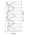
- FIG. 7 shows the luminance uniformity change (black circles in the figure) obtained in the first evaluation and the luminance uniformity change (white circles in the figure) obtained in the second evaluation.
- the horizontal axis represents "arrangement angle of the upper prism sheet 45" - “arrangement angle of the diffusion sheet (pyramid sheet) 43" (hereinafter sometimes simply referred to as “arrangement angle difference"), and the initial state. is 12° (see FIG. 6).
- the "arrangement angle difference” decreases by 10 degrees as the diffusion sheet 43 rotates
- the “arrangement angle difference” increases by 10 degrees as the upper prism sheet 45 rotates.
- the diffusion sheet 43 has an equivalent shape at an arrangement angle of 0° (180°) and 90° (270°)
- the “arrangement angle difference” was converted as follows. That is, if the "arrangement angle difference” is a negative value, add a multiple of 90° to the "arrangement angle difference” to convert it into a value of 0° or more and 90° or less. When exceeding, the multiple of 90 degrees was subtracted from the "arrangement angle difference", and it converted into the value of 0 degrees or more and 90 degrees or less.
- the "arrangement angle difference” is in the range of 0° to 20° and 70° to 90° (that is, the “crossing angle” is in the range of 0° to 20° and 70° to 90° range)
- the brightness uniformity is significantly increased compared to when the “arrangement angle difference” is in the range of 20° to 70° (that is, the “crossing angle” is in the range of 20° to 70°).
- the “arrangement angle difference” is around 10° and 80° (that is, the “crossing angle” is around 10° and 80°)
- the luminance uniformity becomes a maximum value
- the “arrangement angle difference” at the maximum value is A relatively large luminance uniformity is obtained in the range of ⁇ 5°.
- the "crossing angle” is in the range of 0° to 20° and in the range of 70° to 90°, the brightness uniformity increases, and in particular, the “crossing angle” is in the range of about 5° to 15°, or in the range of about 75° to 85° It was found that the luminance uniformity was significantly increased at
- FIG. 8 shows changes in luminance (average value) obtained in the first evaluation described above (black circles in the figure) and changes in luminance (average value) obtained in the second evaluation (white circles in the figure).
- the horizontal axis represents "arrangement angle of the upper prism sheet 45"--"arrangement angle of the diffusion sheet (pyramid sheet) 43", and the arrangement angle difference in the initial state is 12° (see FIG. 6).
- the conversion method of the "arrangement angle difference" is the same as that of the first embodiment.
- the luminance on the vertical axis is expressed as relative luminance with one of the luminance measurement values in the initial state of the optical sheet laminate 100 (when the “arrangement angle difference” is 12°) as 100%. .
- the "arrangement angle difference” is in the range of 20° to 70° (that is, the “crossing angle” is in the range of 20° to 70°), and the “arrangement angle difference” is around 0° or around 90°. (That is, when the "crossing angle” is near 0° or near 90°), the luminance is significantly increased.
- the "arrangement angle difference” is set, for example, in the range of about 10° to 30° (preferably about 15° to 25°), or from 60° to It may be set in the range of about 80° (preferably about 65° to 75°).
- Example 2 Simulation of brightness uniformity
- a lower prism sheet 44 and an upper prism sheet 45 whose prism stretching directions are orthogonal to each other are placed on a stack of three diffusion sheets 43 having a thickness of 110 ⁇ m and having the same structure. I used the arranged one.
- recesses 22 On the first surface 21a (light emitting surface) of the diffusion sheet 43, recesses 22 having an inverted pyramid shape with an apex angle of 90° and a depth of 50 ⁇ m are two-dimensionally arranged at a pitch of 100 ⁇ m.
- the second surface 21b of the diffusion sheet 43 is a flat surface (mirror surface).
- Ridge prisms 44b and 45b having a height of 50 ⁇ m and an apex angle of 90° were arranged at a pitch of 100 ⁇ m on the lower prism sheet 44 and the upper prism sheet 45, respectively, and the thickness of each of the prism sheets 44 and 45 was 130 ⁇ m. .
- the substrate layers 44a and 45a and the ridge prisms 44b and 45b are configured as a one-layer product having the same optical characteristics, and the refractive index and absorption characteristics are similar to those of polycarbonate. characteristics are the same.
- an LED array in which a plurality of blue LEDs with a peak wavelength of 450 nm (full width at half maximum of 16 nm) are two-dimensionally arranged at a pitch of 2.8 mm (specifically, 3 ⁇ 3 in length and width) is used.
- the optical sheet laminate 100 of the embodiment Arranged below the optical sheet laminate 100 of the embodiment (on the side of the diffusion sheet 43), and changing the positional relationship between the diffusion sheet 43 and the prism sheets 44 and 45, the light passing through the optical sheet laminate 100 Luminance uniformity was evaluated by simulation. The luminance uniformity was evaluated with the blue light from the light source 42 without providing the color conversion sheet 46 .
- the lower prism sheet 44 was arranged by rotating the extending direction of the ridge prism portion 44 b counterclockwise by 102° with respect to the X axis (at an arrangement angle of 102°), and the upper prism sheet 45 was arranged. 2, the elongated prism portion 45b is rotated counterclockwise by 12° with respect to the X-axis (at an arrangement angle of 12°) (see FIG. 6).
- the LED array serving as the light source 42 was arranged such that the LEDs were arranged two-dimensionally along two directions, ie, the X-axis direction and the direction perpendicular thereto.
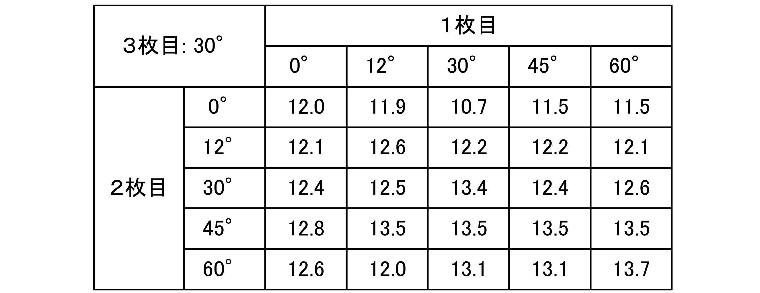
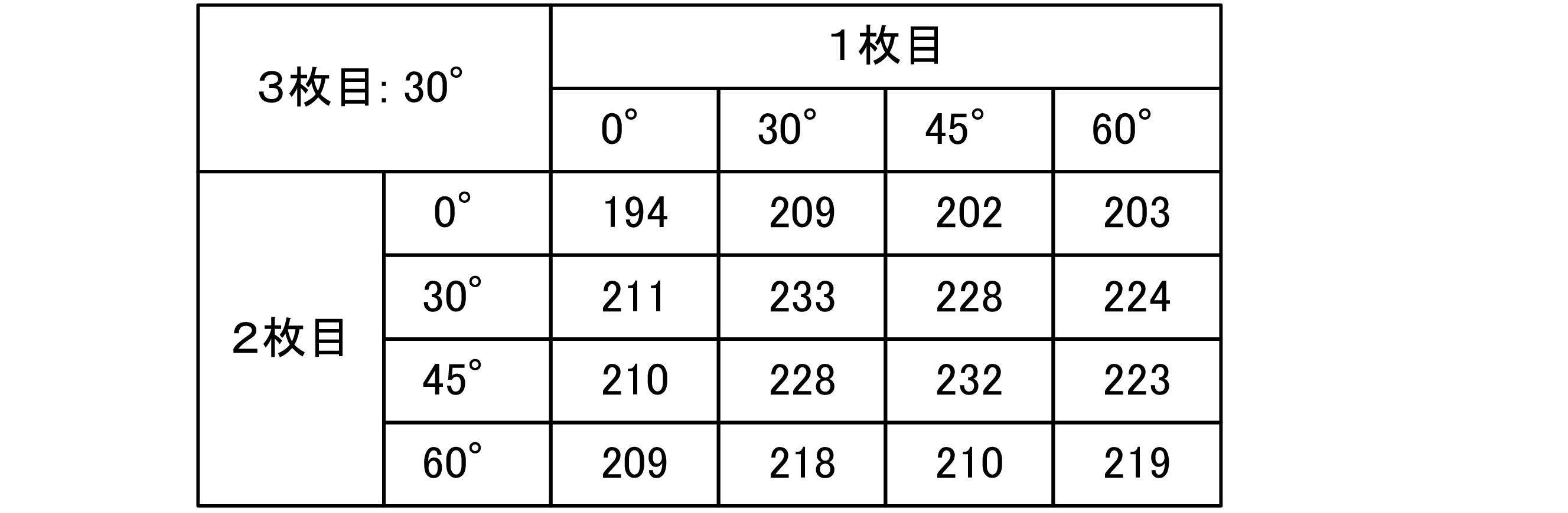
- the arrangement directions of the concave portions 22 are 0°, 12°, 30°, 45°, and 60° (hereinafter referred to as arrangement angles) with respect to the reference LED arrangement direction. placed so that
- the arrangement angle of the diffusion sheet 43 (third sheet) is 0° (the arrangement angle difference with respect to the upper prism sheet 45 is 12°)
- the arrangement angle of the diffusion sheet 43 (first sheet) is is 30° and the arrangement angle of the diffusion sheet 43 (second sheet) is 45°
- the arrangement angle of the diffusion sheet 43 (first sheet) is 45° and the arrangement angle of the diffusion sheet 43 (second sheet) is 45°.
- the luminance uniformity increased significantly.
- the diffusion sheet 43 (third sheet) when the arrangement angle of the diffusion sheet 43 (third sheet) is 30° (the arrangement angle difference with respect to the upper prism sheet 45 is 72°), the diffusion sheet 43 (first sheet) When the arrangement angle of the diffusion sheet 43 (second sheet) is 12° to 60° and the arrangement angle of the diffusion sheet 43 (second sheet) is 45°, the arrangement angle of the diffusion sheet 43 (first sheet) is 30° and the diffusion sheet 43 (second sheet) is arranged at an angle of 45°.
- the arrangement angle was 30°, and when the arrangement angle of the diffusion sheet 43 (first sheet) was 60° and the arrangement angle of the diffusion sheet 43 (second sheet) was 60°, the luminance uniformity was significantly increased. .
- the arrangement angle difference (crossing angle) of the diffusion sheet 43 (third sheet) with respect to the upper prism sheet 45 is in the range of 0° to 20° or 70°. It has been found that the luminance uniformity can be further improved by adjusting the arrangement angle of each diffusion sheet 43 (that is, the arrangement direction of the concave portions 22) in the range of 90°.
- Example 3 (actual measurement of luminance uniformity) will be described below.
- a lower prism sheet 44 and an upper prism sheet 45 whose prism stretching directions are perpendicular to each other are placed on a stack of three diffusion sheets 43 having a thickness of 110 ⁇ m and having the same structure. I used the arranged one.
- the diffusion sheet 43 is a transparent polycarbonate sheet with a thickness of 60 ⁇ m, using a UV curable resin with a refractive index of 1.587. arranged and formed.
- the diffusion sheet 43 was arranged so that the surface (first surface 21a) on which the recesses 22 were formed was the light exit surface.
- the second surface 21b of the diffusion sheet 43 is a matte surface.
- Prism sheets 44 and 45 were formed by providing base material layers 44a and 45a made of PET films with ridged prism portions 44b and 45b using a UV curable acrylic resin made of acrylate.
- the lower prism sheet 44 has a total thickness of 145 ⁇ m, and ridged prisms 44 b having a height of 12 ⁇ m and an apex angle of 94° are arranged at a pitch of 25 ⁇ m.
- the upper prism sheet 45 has a total thickness of 128 ⁇ m, a height of 24 ⁇ m, and ridged prisms 45 b having an apex angle of 93° arranged at a pitch of 51 ⁇ m.
- the light source 42 an LED array in which a plurality of blue LEDs with a peak wavelength of 450 nm (full width at half maximum) are two-dimensionally arranged at a pitch of 2.8 mm is used, and the light source 42 is placed under the optical sheet laminate 100 of the present embodiment.
- the luminance uniformity of the light passing through the optical sheet laminate 100 was examined while changing the arrangement relationship between the diffusion sheet 43 and the prism sheets 44 and 45 .
- the luminance uniformity was examined with the blue light emitted from the light source 42 without providing the color conversion sheet 46 .
- the lower prism sheet 44 was arranged by rotating the extending direction of the ridge prism portion 44 b counterclockwise by 102° with respect to the X axis (at an arrangement angle of 102°), and the upper prism sheet 45 was arranged. 2, the elongated prism portion 45b is rotated counterclockwise by 12° with respect to the X-axis (at an arrangement angle of 12°) (see FIG. 6).
- the LED array serving as the light source 42 was arranged such that the LEDs were arranged two-dimensionally along two directions, ie, the X-axis direction and the direction perpendicular thereto.
- the arrangement directions of the concave portions 22 are arranged at angles of 0°, 30°, 45°, and 60° (hereinafter referred to as arrangement angles) with respect to the reference LED arrangement direction. placed.
- the luminance uniformity evaluation was performed in the same procedure as in Example 1 described above.
- the arrangement angle difference (crossing angle) of the diffusion sheet 43 (third sheet) with respect to the upper prism sheet 45 is in the range of 70° to 90°.
- the luminance uniformity can be further improved by adjusting the arrangement angle of each diffusion sheet 43 (that is, the arrangement direction of the concave portions 22).
- Example 4 luminance uniformity and actual measurement of luminance
- a lower prism sheet 44 and an upper prism sheet 45 whose prism stretching directions are perpendicular to each other are placed on a stack of three diffuser sheets 43 having a thickness of 110 ⁇ m and having the same structure. I used the arranged one.
- an LED array was used in which a plurality of blue LEDs with a peak wavelength of 450 nm (full width at half maximum of 16 nm) were two-dimensionally arranged at a pitch of 2.8 mm.
- the diffusion sheet 43 is formed by two-dimensionally arranging recesses 22 in the shape of an inverted pyramid with an apex angle of 90° at a pitch of 100 ⁇ m.
- the diffusion sheet 43 was arranged so that the surface (first surface 21a) on which the recesses 22 were formed was the light exit surface.
- the second surface 21b of the diffusion sheet 43 is a flat surface.
- Prism sheets 44 and 45 were formed by providing base material layers 44a and 45a made of PET films with ridged prism portions 44b and 45b using a UV curable acrylic resin made of acrylate.
- the lower prism sheet 44 has a total thickness of 90 ⁇ m, a height of 12 ⁇ m, and ridged prisms 44 b having an apex angle of 90° arranged at a pitch of 24 ⁇ m.
- the upper prism sheet 45 has a total thickness of 155 ⁇ m, a height of 25 ⁇ m, and ridge prisms 45 b having an apex angle of 90° arranged at a pitch of 50 ⁇ m.
- a color conversion sheet 46 made of a QD sheet is arranged below the diffusion sheet 43, and an upper light diffusion sheet is arranged above the upper prism sheet 45.
- FIG. The upper light diffusion sheet has a two-layer structure consisting of a substrate layer and a light diffusion layer.
- the substrate layer is mainly composed of a transparent resin for transmitting light, and the light diffusion layer is formed in a resin matrix. It was formed by dispersing resin beads in the
- the arrangement angles of the three diffusion sheets 43 are fixed at 45° and 0°, respectively, and the prism sheets 44 and 45 are rotated.
- the luminance uniformity and the change in luminance were examined.
- the luminance uniformity evaluation was performed in the same procedure as in Example 1 described above, and the average luminance value obtained in the same procedure as in Example 1 was used as the luminance.
- FIGS. 9 and 10 show changes in brightness uniformity and brightness obtained in this example.
- the solid lines show the results when the arrangement angle of the diffusion sheet 43 is set to 45°
- the dashed lines show the results when the arrangement angle of the diffusion sheet 43 is set to 0°.
- the horizontal axis of FIGS. 9 and 10 indicates the arrangement angle of the upper prism sheet 45 (rotational angle of the extending direction of the prismatic protrusions 45b (ridge line) with respect to the arrangement direction (X direction) of the light sources 42).
- the arrangement angle of the lower prism sheet 44 (the rotation angle of the extending direction of the ridge prisms 44b (ridge line) with respect to the arrangement direction (X direction) of the light source 42) is "the arrangement angle of the upper prism sheet 45" +90°. be.
- the arrangement angle of the diffusion sheet 43 when the arrangement angle of the diffusion sheet 43 is 0°, the arrangement angle of the upper prism sheet 45 ranges from about 0° to about 20°, from about 70° to about 110°, And the brightness uniformity was improved in the range from about 160° to about 180°. Further, when the arrangement angle of the diffusion sheet 43 is 45°, the luminance uniformity is improved when the arrangement angle of the upper prism sheet 45 ranges from about 25° to about 65° and from about 115° to about 155°. Improved.
- the arrangement angle of the diffusion sheet 43 when the arrangement angle of the diffusion sheet 43 is set to 45°, the arrangement angle of the prism sheets 44 and 45 is greater than that of the case where the diffusion sheet 43 is set to 0°. , the luminance uniformity was improved. Specifically, the average value of luminance uniformity when the arrangement angle of the diffusion sheet 43 is set to 45° is about 180, whereas the luminance when the arrangement angle of the diffusion sheet 43 is set to 0° The average uniformity value was about 150. When the arrangement angle of the diffusion sheet 43 is set to 45°, compared with the case of setting the arrangement angle to 0°, the luminance uniformity is improved by about three times the variation width depending on the arrangement angle of the prism sheets 44 and 45 .
- the luminance on the vertical axis is expressed as a relative luminance with one of the luminance measurement values when the diffusion sheet 43 is arranged at an angle of 0° as 100%. , means “luminance reduction greater than 2%”.
- the optical sheet laminate 100 is composed of the diffusion sheet 43 , the prism sheets 44 and 45 and the color conversion sheet 46 .
- the optical sheet laminate 100 may further include optical sheets other than the diffusion sheet 43 , the prism sheets 44 and 45 and the color conversion sheet 46 .
- the inverted polygonal pyramid shape of the concave portion 22 provided in the first surface 21a of the diffusion sheet 43 included in the optical sheet laminate 100 is an inverted square pyramid.
- Other shapes, such as an inverted triangular pyramid or an inverted hexagonal pyramid, may also be used.
- a row of protrusions such as a prism portion may be provided.
- the second surface 21b of the diffusion sheet 43 is a flat surface (mirror surface) or an embossed surface.
- a row of protrusions such as a prism portion may be provided.
- liquid crystal display panel 1 TFT substrate 2 CF substrate 3 liquid crystal layer 5 liquid crystal display panel 6 first polarizing plate 7 second polarizing plate 21 base material layer 21a first surface 21b second surface 22 concave portion 40 backlight unit 41 reflective sheet 42 light source 43 diffusion sheet 44 Lower prism sheet 44a Base material layer 44b Ridge prism part 45 Upper prism sheet 45a Base material layer 45b Ridge prism part 46 Color conversion sheet 50 Liquid crystal display device 50a Display screen 100 Optical sheet laminate 111 Ridge line 112 Center of recess (inverted pyramid vertex)
Abstract
Description
以下、実施形態に係る光学シート積層体、バックライトユニット、液晶表示装置、情報機器、及びバックライトユニットの製造方法について、図面を参照しながら説明する。尚、本開示の範囲は、以下の実施の形態に限定されず、本開示の技術的思想の範囲内で任意に変更可能である。また、各図面は、本開示を概念的に説明するためのものであるから、理解容易のために必要に応じて寸法、比又は数を誇張又は簡略化して表す場合がある。
図1に示すように、液晶表示装置50は、液晶表示パネル5と、液晶表示パネル5の下面に貼付された第1偏光板6と、液晶表示パネル5の上面に貼付された第2偏光板7と、液晶表示パネル5の背面側に第1偏光板6を介して設けられたバックライトユニット40とを備えている。
図2に示すように、バックライトユニット40は、反射シート41と、反射シート41上に2次元状に配置された複数の光源42と、複数の光源42の上側に設けられた光学シート積層体100とを備える。光学シート積層体100は、光源42の側に配置された拡散シート43と、拡散シート43の上側(表示画面50aの側)に設けられた一対のプリズムシート44及び45とを有する。また、光学シート積層体100は、光源42と拡散シート43との間に色変換シート46を有する。尚、光学シート積層体100を構成する各シートは、フィルム状であってもよいし、プレート(板)状であってもよい。
反射シート41は、例えば、白色のポリエチレンテレフタレート樹脂製のフィルム、銀蒸着フィルム等により構成される。
光源42は、例えば、CIE1931の色度座標においてx<0.24、y<0.18の光を発する青色光源であってもよい。光源42の種類は特に限定されないが、例えばLED素子やレーザー素子等であってもよく、コスト、生産性等の観点からLED素子を用いてもよい。LEDの出光角度特性を調節するために、LED素子にレンズを装着してもよい。光源42がLED素子から構成される場合、LED素子(チップ)は、平面視した場合に長方形状を有していてもよく、その場合、一辺の長さは50μm以上(好ましくは100μm以上)1mm以下であってもよい。LEDチップは、2次元的に一定の間隔で反射シート41上に配置されてもよい。複数のLEDチップを等間隔で配置する場合、隣り合う2つのチップの中心間距離は、0.5mm以上(好ましくは2mm以上)20mm以下であってもよい。
拡散シート43は、図2及び図3に示すように、基材層21を有する。拡散シート43(基材層21)は、光出射面となる第1面21aと、光入射面となる第2面21bとを有する。すなわち、拡散シート43は、第2面21bを光源42の方に向けて配置される。基材層21のマトリックスとなる樹脂は、光を透過させる材料で構成されていれば、特に限定されないが、例えば、アクリル、ポリスチレン、ポリカーボネート、MS(メチルメタクリレート・スチレン共重合)樹脂、ポリエチレンテレフタレート、ポリエチレンナフタレート、セルロールアセテート、ポリイミド等であってもよい。基材層21は、拡散剤その他の添加剤を含んでいてもよいし、或いは、実質的に添加剤を含有しなくてもよい。基材層21に含有可能な添加剤は、特に限定されないが、例えば、シリカ、酸化チタン、水酸化アルミニウム、硫酸バリウム等の無機粒子であってもよいし、例えば、アクリル、アクリルニトリル、シリコーン、ポリスチレン、ポリアミド等の有機粒子であってよい。
拡散シート43の製造方法は、特に限定されないが、例えば、押し出し成型法、射出成型法などを用いてもよい。
プリズムシート44及び45は、光線を透過させる必要があるので、透明(例えば無色透明)の合成樹脂を主成分として形成される。プリズムシート44及び45は、一体に形成されてもよい。図2に示すように、下側プリズムシート44は、基材層44aと、基材層44aの表面に積層される複数の突条プリズム部44bからなる突起列とを有する。同様に、上側プリズムシート45は、基材層45aと、基材層45aの表面に積層される複数の突条プリズム部45bからなる突起列とを有する。突条プリズム部44b及び45bはそれぞれ、基材層44a及び45aの表面にストライプ状に積層される。突条プリズム部44b及び45bはそれぞれ、裏面が基材層44a及び45aの表面に接する三角柱状体である。突条プリズム部44bの延伸方向と突条プリズム部45bの延伸方向とは、互いに直交する。これにより、拡散シート43から入射される光線を下側プリズムシート44によって法線方向側に屈折させ、さらに下側プリズムシート44から出射される光線を上側プリズムシート45によって表示画面50aに対して略垂直に進むように屈折させることができる。
色変換シート46は、光源42からの光を、任意の色(例えば緑色や赤色)の波長をピーク波長とする光に変換する波長変換シートである。例えば、光源42が青色光源であれば、色変換シート46は、波長450nmの青色光を、波長540nmの緑色光と波長650nmの赤色光に変換する。この場合、波長450nmの青色光を発する光源42を用いると、色変換シート46によって青色光が部分的に緑色光と赤色光に変換されるので、色変換シート46を透過した光は白色光になる。色変換シート46としては、例えば、QD(量子ドット)シートや蛍光シート等を用いてもよい。光源42として白色光源を用いる場合、色変換シート46は設けなくてもよい。
図示は省略しているが、プリズムシート44及び45の上側(表示画面50aの側)に偏光シートを設けてもよい。偏光シートは、バックライトユニット40から出射された光が液晶表示装置50の第1偏光板6に吸収されることを防止することによって、表示画面50aの輝度を向上させる。
本実施形態の光学シート積層体100は、バックライトユニット40に組み込まれる。光学シート積層体100は、第1面21aに略逆四角錐状の複数の凹部22が二次元マトリクス状に配列された複数の拡散シート43と、突条プリズム部44b及び45bの延伸方向(以下、プリズム延伸方向ということもある)が互いに直交する一対のプリズムシート44及び45とを備える。光学シート積層体100において、例えば図5に示すように、複数の拡散シート43のうち一対のプリズムシート44及び45に最も近い拡散シート43における複数の凹部22の配列方向は、プリズム延伸方向に対して0°以上20°以下、又は70°以上90°以下の角度で交差する。尚、図5では、簡単のため、突条プリズム部44bの図示を省略しているが、突条プリズム部44bの延伸方向と突条プリズム部45bの延伸方向とは互いに直交するため、突条プリズム部45bの延伸方向が前述の交差角度範囲を満たす場合、突条プリズム部44bの延伸方向も前述の交差角度範囲を満たす。
<実施例1>
以下、実施例1(輝度均一性の実測)について説明する。
図8は、前述の第1評価で得られた輝度(平均値)の変化(図中の黒丸)及び第2評価で得られた輝度(平均値)の変化(図中の白丸)を示す。図8において、横軸は、「上側プリズムシ-ト45の配置角度」-「拡散シート(ピラミッドシート)43の配置角度」を表し、初期状態の配置角度差は12°(図6参照)である。尚、「配置角度差」の換算方法は、前述の実施例1と同じである。また、図8において、縦軸の輝度は、光学シート積層体100の初期状態(「配置角度差」が12°のとき)の輝度測定値の1つを100%とした相対輝度で表している。
以下、実施例2(輝度均一性のシミュレーション)について説明する。

以下、実施例3(輝度均一性の実測)について説明する。
以下、実施例4(輝度均一性及び輝度の実測)について説明する。
前記実施形態(実施例を含む。以下同じ。)では、拡散シート43とプリズムシート44及び45と色変換シート46とから光学シート積層体100を構成した。しかし、光学シート積層体100は、拡散シート43、プリズムシート44、45及び色変換シート46以外の他の光学シートをさらに含んでいてもよい。
2 CF基板
3 液晶層
5 液晶表示パネル
6 第1偏光板
7 第2偏光板
21 基材層
21a 第1面
21b 第2面
22 凹部
40 バックライトユニット
41 反射シート
42 光源
43 拡散シート
44 下側プリズムシート
44a 基材層
44b 突条プリズム部
45 上側プリズムシート
45a 基材層
45b 突条プリズム部
46 色変換シート
50 液晶表示装置
50a 表示画面
100 光学シート積層体
111 稜線
112 凹部中心(逆ピラミッド頂点)
Claims (9)
- バックライトユニットに組み込まれる光学シート積層体であって、
少なくとも一面に略逆四角錐状の複数の凹部が二次元マトリクス状に配列された複数の拡散シートと、
プリズム延伸方向が互いに直交する一対のプリズムシートと
を備え、
前記複数の拡散シートのうち前記一対のプリズムシートに最も近い第1拡散シートにおける前記複数の凹部の第1配列方向は、前記プリズム延伸方向に対して、0°以上20°以下、又は70°以上90°以下の角度で交差する
光学シート積層体。 - 前記第1拡散シートを除く前記複数の拡散シートのうち少なくとも1つの第2拡散シートにおける前記複数の凹部の第2配列方向は、前記第1配列方向と実質的に同じである
請求項1に記載の光学シート積層体。 - 前記第1拡散シートを除く前記複数の拡散シートのうち少なくとも1つの第2拡散シートにおける前記複数の凹部の第2配列方向は、前記第1配列方向と異なる
請求項1に記載の光学シート積層体。 - 液晶表示装置に組み込まれ、光源から発せられた光を表示画面側に導くバックライトユニットであって、
前記表示画面と前記光源との間に、請求項1~3のいずれか1項の光学シート積層体を備え、
前記複数の拡散シートは、前記光源と前記一対のプリズムシートとの間に配置される
バックライトユニット。 - 前記光源は、前記複数の拡散シートから見て前記表示画面の反対側に設けられた反射シートの上に配置される
請求項4に記載のバックライトユニット。 - 前記光源と前記複数の拡散シートとの間の距離は、5mm以下である
請求項4に記載のバックライトユニット。 - 請求項4に記載のバックライトユニットと、
液晶表示パネルとを備える
液晶表示装置。 - 請求項7に記載の液晶表示装置を備える情報機器。
- 液晶表示装置に組み込まれ、光源から発せられた光を表示画面側に導くバックライトユニットの製造方法であって、
前記光源から見て前記表示画面側に、少なくとも一面に略逆四角錐状の複数の凹部が二次元マトリクス状に配列された複数の拡散シートを配置する工程と、
前記複数の拡散シートから見て前記表示画面側に、プリズム延伸方向が互いに直交する一対のプリズムシートを配置する工程とを備え、
前記複数の拡散シートを配置する工程では、前記複数の拡散シートのそれぞれにおける前記複数の凹部の配列方向と前記プリズム延伸方向との交差角度を変化させながら輝度均一性を評価し、当該評価結果に基づいて、前記複数の拡散シートのそれぞれにおける前記複数の凹部の配列方向を決定する
バックライトユニットの製造方法。
Priority Applications (2)
| Application Number | Priority Date | Filing Date | Title |
|---|---|---|---|
| CN202280047966.3A CN117716281A (zh) | 2021-09-28 | 2022-06-29 | 光学片层叠体、背光单元、液晶显示装置、信息设备以及背光单元的制造方法 |
| KR1020247002076A KR20240013285A (ko) | 2021-09-28 | 2022-06-29 | 광학 시트 적층체, 백라이트 유닛, 액정표시장치, 정보기기, 및 백라이트 유닛의 제조방법 |
Applications Claiming Priority (4)
| Application Number | Priority Date | Filing Date | Title |
|---|---|---|---|
| JP2021157806 | 2021-09-28 | ||
| JP2021-157806 | 2021-09-28 | ||
| JP2022-100220 | 2022-06-22 | ||
| JP2022100220A JP7289001B2 (ja) | 2021-09-28 | 2022-06-22 | 光学シート積層体、バックライトユニット、液晶表示装置、情報機器、及びバックライトユニットの製造方法 |
Publications (1)
| Publication Number | Publication Date |
|---|---|
| WO2023053643A1 true WO2023053643A1 (ja) | 2023-04-06 |
Family
ID=85779876
Family Applications (1)
| Application Number | Title | Priority Date | Filing Date |
|---|---|---|---|
| PCT/JP2022/025924 WO2023053643A1 (ja) | 2021-09-28 | 2022-06-29 | 光学シート積層体、バックライトユニット、液晶表示装置、情報機器、及びバックライトユニットの製造方法 |
Country Status (5)
| Country | Link |
|---|---|
| JP (1) | JP7289001B2 (ja) |
| KR (1) | KR20240013285A (ja) |
| CN (1) | CN117716281A (ja) |
| TW (1) | TW202314348A (ja) |
| WO (1) | WO2023053643A1 (ja) |
Citations (2)
| Publication number | Priority date | Publication date | Assignee | Title |
|---|---|---|---|---|
| JP2011129277A (ja) | 2009-12-15 | 2011-06-30 | Toppan Printing Co Ltd | バックライトユニット及びディスプレイ装置 |
| WO2020100390A1 (ja) * | 2018-11-16 | 2020-05-22 | 恵和株式会社 | 光学シート、バックライトユニット、液晶表示装置及び情報機器 |
-
2022
- 2022-06-22 JP JP2022100220A patent/JP7289001B2/ja active Active
- 2022-06-29 WO PCT/JP2022/025924 patent/WO2023053643A1/ja active Application Filing
- 2022-06-29 KR KR1020247002076A patent/KR20240013285A/ko active Search and Examination
- 2022-06-29 CN CN202280047966.3A patent/CN117716281A/zh active Pending
- 2022-07-08 TW TW111125637A patent/TW202314348A/zh unknown
Patent Citations (2)
| Publication number | Priority date | Publication date | Assignee | Title |
|---|---|---|---|---|
| JP2011129277A (ja) | 2009-12-15 | 2011-06-30 | Toppan Printing Co Ltd | バックライトユニット及びディスプレイ装置 |
| WO2020100390A1 (ja) * | 2018-11-16 | 2020-05-22 | 恵和株式会社 | 光学シート、バックライトユニット、液晶表示装置及び情報機器 |
Also Published As
| Publication number | Publication date |
|---|---|
| TW202314348A (zh) | 2023-04-01 |
| JP2023048982A (ja) | 2023-04-07 |
| KR20240013285A (ko) | 2024-01-30 |
| CN117716281A (zh) | 2024-03-15 |
| JP7289001B2 (ja) | 2023-06-08 |
Similar Documents
| Publication | Publication Date | Title |
|---|---|---|
| KR102199264B1 (ko) | 광학 시트, 백라이트 유닛, 액정 표시 장치 및 정보 기기 | |
| WO2023007917A1 (ja) | 光学シート積層体、バックライトユニット、液晶表示装置、及び情報機器 | |
| JP7289001B2 (ja) | 光学シート積層体、バックライトユニット、液晶表示装置、情報機器、及びバックライトユニットの製造方法 | |
| WO2023282055A1 (ja) | 光学シート積層体、バックライトユニット、液晶表示装置、情報機器、及びバックライトユニットの製造方法 | |
| JP7275341B1 (ja) | 光拡散シート、バックライトユニット、液晶表示装置、情報機器、及びバックライトユニットの製造方法 | |
| WO2023282054A1 (ja) | 光学シート積層体、バックライトユニット、液晶表示装置、情報機器、及びバックライトユニットの製造方法 | |
| JP2021162840A (ja) | 光学シート、バックライトユニット、液晶表示装置及び情報機器 | |
| WO2023037651A1 (ja) | 光学シート積層体、バックライトユニット、液晶表示装置、情報機器、及びバックライトユニットの製造方法 | |
| WO2023145199A1 (ja) | 光学シート積層体、バックライトユニット、液晶表示装置、情報機器、及びバックライトユニットの製造方法 | |
| WO2022196162A1 (ja) | 光拡散シート、バックライトユニット、液晶表示装置及び情報機器 | |
| TWI832256B (zh) | 光擴散片、背光單元、液晶顯示裝置以及資訊設備 | |
| JP7436560B2 (ja) | 光拡散シート、バックライトユニット、液晶表示装置及び情報機器 | |
| WO2023090189A1 (ja) | 光学シート積層体、バックライトユニット、液晶表示装置、情報機器、及び光学シート積層体の製造方法 | |
| JP2022144447A (ja) | 光拡散シート、バックライトユニット、液晶表示装置及び情報機器 | |
| JP2023113017A (ja) | 光拡散シート、バックライトユニット、液晶表示装置及び情報機器 | |
| JP2023174543A (ja) | 光拡散シート、バックライトユニット、液晶表示装置、及び情報機器 | |
| CN116324531A (zh) | 光扩散片、背光单元、液晶显示装置、信息设备以及背光单元的制造方法 |
Legal Events
| Date | Code | Title | Description |
|---|---|---|---|
| 121 | Ep: the epo has been informed by wipo that ep was designated in this application |
Ref document number: 22875522 Country of ref document: EP Kind code of ref document: A1 |
|
| ENP | Entry into the national phase |
Ref document number: 20247002076 Country of ref document: KR Kind code of ref document: A |
|
| WWE | Wipo information: entry into national phase |
Ref document number: 1020247002076 Country of ref document: KR |
|
| WWE | Wipo information: entry into national phase |
Ref document number: 2022875522 Country of ref document: EP |
|
| ENP | Entry into the national phase |
Ref document number: 2022875522 Country of ref document: EP Effective date: 20240318 |