WO2023053639A1 - 電池および電池の製造方法 - Google Patents
電池および電池の製造方法 Download PDFInfo
- Publication number
- WO2023053639A1 WO2023053639A1 PCT/JP2022/025774 JP2022025774W WO2023053639A1 WO 2023053639 A1 WO2023053639 A1 WO 2023053639A1 JP 2022025774 W JP2022025774 W JP 2022025774W WO 2023053639 A1 WO2023053639 A1 WO 2023053639A1
- Authority
- WO
- WIPO (PCT)
- Prior art keywords
- counter electrode
- electrode
- layer
- current collector
- battery
- Prior art date
Links
- 238000004519 manufacturing process Methods 0.000 title claims description 20
- 239000007784 solid electrolyte Substances 0.000 claims abstract description 78
- 238000010248 power generation Methods 0.000 claims abstract description 71
- 238000000605 extraction Methods 0.000 claims abstract description 52
- 239000007772 electrode material Substances 0.000 claims description 128
- 239000011347 resin Substances 0.000 claims description 18
- 229920005989 resin Polymers 0.000 claims description 18
- 238000007789 sealing Methods 0.000 claims description 17
- 239000000463 material Substances 0.000 description 66
- 238000000034 method Methods 0.000 description 24
- 238000009413 insulation Methods 0.000 description 12
- 239000011248 coating agent Substances 0.000 description 10
- 238000000576 coating method Methods 0.000 description 10
- 239000011810 insulating material Substances 0.000 description 10
- 239000011149 active material Substances 0.000 description 9
- 238000005520 cutting process Methods 0.000 description 9
- 229910052751 metal Inorganic materials 0.000 description 9
- 239000002184 metal Substances 0.000 description 9
- 239000002131 composite material Substances 0.000 description 7
- 239000004020 conductor Substances 0.000 description 7
- 238000001035 drying Methods 0.000 description 7
- 239000007774 positive electrode material Substances 0.000 description 7
- 229910003480 inorganic solid Inorganic materials 0.000 description 6
- 239000002203 sulfidic glass Substances 0.000 description 6
- PXHVJJICTQNCMI-UHFFFAOYSA-N Nickel Chemical compound [Ni] PXHVJJICTQNCMI-UHFFFAOYSA-N 0.000 description 5
- 229910052744 lithium Inorganic materials 0.000 description 5
- 229910044991 metal oxide Inorganic materials 0.000 description 5
- 150000004706 metal oxides Chemical class 0.000 description 5
- 239000007773 negative electrode material Substances 0.000 description 5
- WHXSMMKQMYFTQS-UHFFFAOYSA-N Lithium Chemical compound [Li] WHXSMMKQMYFTQS-UHFFFAOYSA-N 0.000 description 4
- 239000000470 constituent Substances 0.000 description 4
- 230000014509 gene expression Effects 0.000 description 4
- 238000005488 sandblasting Methods 0.000 description 4
- 239000000126 substance Substances 0.000 description 4
- 239000000758 substrate Substances 0.000 description 4
- 238000003466 welding Methods 0.000 description 4
- OKTJSMMVPCPJKN-UHFFFAOYSA-N Carbon Chemical compound [C] OKTJSMMVPCPJKN-UHFFFAOYSA-N 0.000 description 3
- 239000002033 PVDF binder Substances 0.000 description 3
- 239000011230 binding agent Substances 0.000 description 3
- 230000001680 brushing effect Effects 0.000 description 3
- 238000010276 construction Methods 0.000 description 3
- 239000010949 copper Substances 0.000 description 3
- 239000002001 electrolyte material Substances 0.000 description 3
- 239000003822 epoxy resin Substances 0.000 description 3
- 238000005530 etching Methods 0.000 description 3
- 238000007646 gravure printing Methods 0.000 description 3
- 238000010438 heat treatment Methods 0.000 description 3
- 238000005304 joining Methods 0.000 description 3
- 239000011777 magnesium Substances 0.000 description 3
- 239000000203 mixture Substances 0.000 description 3
- 239000002245 particle Substances 0.000 description 3
- 238000007747 plating Methods 0.000 description 3
- 229920000647 polyepoxide Polymers 0.000 description 3
- 229920002981 polyvinylidene fluoride Polymers 0.000 description 3
- 238000007639 printing Methods 0.000 description 3
- 230000001681 protective effect Effects 0.000 description 3
- 238000007650 screen-printing Methods 0.000 description 3
- 229910000679 solder Inorganic materials 0.000 description 3
- 238000005476 soldering Methods 0.000 description 3
- 239000007921 spray Substances 0.000 description 3
- 238000003892 spreading Methods 0.000 description 3
- 230000007480 spreading Effects 0.000 description 3
- RYGMFSIKBFXOCR-UHFFFAOYSA-N Copper Chemical compound [Cu] RYGMFSIKBFXOCR-UHFFFAOYSA-N 0.000 description 2
- UQSXHKLRYXJYBZ-UHFFFAOYSA-N Iron oxide Chemical compound [Fe]=O UQSXHKLRYXJYBZ-UHFFFAOYSA-N 0.000 description 2
- 229910001216 Li2S Inorganic materials 0.000 description 2
- XLOMVQKBTHCTTD-UHFFFAOYSA-N Zinc monoxide Chemical compound [Zn]=O XLOMVQKBTHCTTD-UHFFFAOYSA-N 0.000 description 2
- 239000006230 acetylene black Substances 0.000 description 2
- 238000005275 alloying Methods 0.000 description 2
- 229910052782 aluminium Inorganic materials 0.000 description 2
- XAGFODPZIPBFFR-UHFFFAOYSA-N aluminium Chemical compound [Al] XAGFODPZIPBFFR-UHFFFAOYSA-N 0.000 description 2
- 230000004888 barrier function Effects 0.000 description 2
- 230000015572 biosynthetic process Effects 0.000 description 2
- 229910052802 copper Inorganic materials 0.000 description 2
- 238000010586 diagram Methods 0.000 description 2
- 239000011888 foil Substances 0.000 description 2
- 229910010272 inorganic material Inorganic materials 0.000 description 2
- 239000011147 inorganic material Substances 0.000 description 2
- 150000002500 ions Chemical class 0.000 description 2
- 229910052749 magnesium Inorganic materials 0.000 description 2
- 239000007769 metal material Substances 0.000 description 2
- 230000004048 modification Effects 0.000 description 2
- 238000012986 modification Methods 0.000 description 2
- 229910052759 nickel Inorganic materials 0.000 description 2
- 239000003973 paint Substances 0.000 description 2
- 238000005498 polishing Methods 0.000 description 2
- 230000002265 prevention Effects 0.000 description 2
- 230000008569 process Effects 0.000 description 2
- 239000002904 solvent Substances 0.000 description 2
- 238000004544 sputter deposition Methods 0.000 description 2
- 229910001220 stainless steel Inorganic materials 0.000 description 2
- 239000010935 stainless steel Substances 0.000 description 2
- 238000007740 vapor deposition Methods 0.000 description 2
- 229920000178 Acrylic resin Polymers 0.000 description 1
- 239000004925 Acrylic resin Substances 0.000 description 1
- 229910018091 Li 2 S Inorganic materials 0.000 description 1
- FYYHWMGAXLPEAU-UHFFFAOYSA-N Magnesium Chemical compound [Mg] FYYHWMGAXLPEAU-UHFFFAOYSA-N 0.000 description 1
- VYPSYNLAJGMNEJ-UHFFFAOYSA-N Silicium dioxide Chemical compound O=[Si]=O VYPSYNLAJGMNEJ-UHFFFAOYSA-N 0.000 description 1
- GWEVSGVZZGPLCZ-UHFFFAOYSA-N Titan oxide Chemical compound O=[Ti]=O GWEVSGVZZGPLCZ-UHFFFAOYSA-N 0.000 description 1
- 229910021536 Zeolite Inorganic materials 0.000 description 1
- NXPZICSHDHGMGT-UHFFFAOYSA-N [Co].[Mn].[Li] Chemical compound [Co].[Mn].[Li] NXPZICSHDHGMGT-UHFFFAOYSA-N 0.000 description 1
- PFYQFCKUASLJLL-UHFFFAOYSA-N [Co].[Ni].[Li] Chemical compound [Co].[Ni].[Li] PFYQFCKUASLJLL-UHFFFAOYSA-N 0.000 description 1
- KLARSDUHONHPRF-UHFFFAOYSA-N [Li].[Mn] Chemical compound [Li].[Mn] KLARSDUHONHPRF-UHFFFAOYSA-N 0.000 description 1
- SOXUFMZTHZXOGC-UHFFFAOYSA-N [Li].[Mn].[Co].[Ni] Chemical compound [Li].[Mn].[Co].[Ni] SOXUFMZTHZXOGC-UHFFFAOYSA-N 0.000 description 1
- 238000005452 bending Methods 0.000 description 1
- BRPQOXSCLDDYGP-UHFFFAOYSA-N calcium oxide Chemical compound [O-2].[Ca+2] BRPQOXSCLDDYGP-UHFFFAOYSA-N 0.000 description 1
- 239000000292 calcium oxide Substances 0.000 description 1
- ODINCKMPIJJUCX-UHFFFAOYSA-N calcium oxide Inorganic materials [Ca]=O ODINCKMPIJJUCX-UHFFFAOYSA-N 0.000 description 1
- 229910000420 cerium oxide Inorganic materials 0.000 description 1
- 230000008859 change Effects 0.000 description 1
- 239000003795 chemical substances by application Substances 0.000 description 1
- 230000008602 contraction Effects 0.000 description 1
- 230000006866 deterioration Effects 0.000 description 1
- QHGJSLXSVXVKHZ-UHFFFAOYSA-N dilithium;dioxido(dioxo)manganese Chemical compound [Li+].[Li+].[O-][Mn]([O-])(=O)=O QHGJSLXSVXVKHZ-UHFFFAOYSA-N 0.000 description 1
- HNPSIPDUKPIQMN-UHFFFAOYSA-N dioxosilane;oxo(oxoalumanyloxy)alumane Chemical compound O=[Si]=O.O=[Al]O[Al]=O HNPSIPDUKPIQMN-UHFFFAOYSA-N 0.000 description 1
- 238000007599 discharging Methods 0.000 description 1
- 230000000694 effects Effects 0.000 description 1
- 238000010292 electrical insulation Methods 0.000 description 1
- 239000012777 electrically insulating material Substances 0.000 description 1
- 239000003792 electrolyte Substances 0.000 description 1
- 239000010408 film Substances 0.000 description 1
- 239000012530 fluid Substances 0.000 description 1
- 239000011521 glass Substances 0.000 description 1
- 239000010439 graphite Substances 0.000 description 1
- 229910002804 graphite Inorganic materials 0.000 description 1
- 238000000227 grinding Methods 0.000 description 1
- 230000020169 heat generation Effects 0.000 description 1
- JEIPFZHSYJVQDO-UHFFFAOYSA-N iron(III) oxide Inorganic materials O=[Fe]O[Fe]=O JEIPFZHSYJVQDO-UHFFFAOYSA-N 0.000 description 1
- 238000010030 laminating Methods 0.000 description 1
- GLNWILHOFOBOFD-UHFFFAOYSA-N lithium sulfide Chemical compound [Li+].[Li+].[S-2] GLNWILHOFOBOFD-UHFFFAOYSA-N 0.000 description 1
- 230000000873 masking effect Effects 0.000 description 1
- 150000002739 metals Chemical class 0.000 description 1
- QGLKJKCYBOYXKC-UHFFFAOYSA-N nonaoxidotritungsten Chemical compound O=[W]1(=O)O[W](=O)(=O)O[W](=O)(=O)O1 QGLKJKCYBOYXKC-UHFFFAOYSA-N 0.000 description 1
- TWNQGVIAIRXVLR-UHFFFAOYSA-N oxo(oxoalumanyloxy)alumane Chemical compound O=[Al]O[Al]=O TWNQGVIAIRXVLR-UHFFFAOYSA-N 0.000 description 1
- BMMGVYCKOGBVEV-UHFFFAOYSA-N oxo(oxoceriooxy)cerium Chemical compound [Ce]=O.O=[Ce]=O BMMGVYCKOGBVEV-UHFFFAOYSA-N 0.000 description 1
- RVTZCBVAJQQJTK-UHFFFAOYSA-N oxygen(2-);zirconium(4+) Chemical compound [O-2].[O-2].[Zr+4] RVTZCBVAJQQJTK-UHFFFAOYSA-N 0.000 description 1
- CYQAYERJWZKYML-UHFFFAOYSA-N phosphorus pentasulfide Chemical compound S1P(S2)(=S)SP3(=S)SP1(=S)SP2(=S)S3 CYQAYERJWZKYML-UHFFFAOYSA-N 0.000 description 1
- 229920001721 polyimide Polymers 0.000 description 1
- 239000009719 polyimide resin Substances 0.000 description 1
- 238000003825 pressing Methods 0.000 description 1
- 229910052814 silicon oxide Inorganic materials 0.000 description 1
- 239000007787 solid Substances 0.000 description 1
- 239000010409 thin film Substances 0.000 description 1
- OGIDPMRJRNCKJF-UHFFFAOYSA-N titanium oxide Inorganic materials [Ti]=O OGIDPMRJRNCKJF-UHFFFAOYSA-N 0.000 description 1
- 229910001930 tungsten oxide Inorganic materials 0.000 description 1
- XLYOFNOQVPJJNP-UHFFFAOYSA-N water Substances O XLYOFNOQVPJJNP-UHFFFAOYSA-N 0.000 description 1
- 238000004078 waterproofing Methods 0.000 description 1
- 239000010457 zeolite Substances 0.000 description 1
- 239000011787 zinc oxide Substances 0.000 description 1
- 229910001928 zirconium oxide Inorganic materials 0.000 description 1
Images


Classifications
-
- H—ELECTRICITY
- H01—ELECTRIC ELEMENTS
- H01M—PROCESSES OR MEANS, e.g. BATTERIES, FOR THE DIRECT CONVERSION OF CHEMICAL ENERGY INTO ELECTRICAL ENERGY
- H01M10/00—Secondary cells; Manufacture thereof
- H01M10/05—Accumulators with non-aqueous electrolyte
- H01M10/052—Li-accumulators
-
- H—ELECTRICITY
- H01—ELECTRIC ELEMENTS
- H01M—PROCESSES OR MEANS, e.g. BATTERIES, FOR THE DIRECT CONVERSION OF CHEMICAL ENERGY INTO ELECTRICAL ENERGY
- H01M10/00—Secondary cells; Manufacture thereof
- H01M10/05—Accumulators with non-aqueous electrolyte
- H01M10/056—Accumulators with non-aqueous electrolyte characterised by the materials used as electrolytes, e.g. mixed inorganic/organic electrolytes
- H01M10/0561—Accumulators with non-aqueous electrolyte characterised by the materials used as electrolytes, e.g. mixed inorganic/organic electrolytes the electrolyte being constituted of inorganic materials only
- H01M10/0562—Solid materials
-
- H—ELECTRICITY
- H01—ELECTRIC ELEMENTS
- H01M—PROCESSES OR MEANS, e.g. BATTERIES, FOR THE DIRECT CONVERSION OF CHEMICAL ENERGY INTO ELECTRICAL ENERGY
- H01M10/00—Secondary cells; Manufacture thereof
- H01M10/05—Accumulators with non-aqueous electrolyte
- H01M10/058—Construction or manufacture
- H01M10/0585—Construction or manufacture of accumulators having only flat construction elements, i.e. flat positive electrodes, flat negative electrodes and flat separators
-
- H—ELECTRICITY
- H01—ELECTRIC ELEMENTS
- H01M—PROCESSES OR MEANS, e.g. BATTERIES, FOR THE DIRECT CONVERSION OF CHEMICAL ENERGY INTO ELECTRICAL ENERGY
- H01M50/00—Constructional details or processes of manufacture of the non-active parts of electrochemical cells other than fuel cells, e.g. hybrid cells
- H01M50/50—Current conducting connections for cells or batteries
- H01M50/531—Electrode connections inside a battery casing
- H01M50/533—Electrode connections inside a battery casing characterised by the shape of the leads or tabs
-
- H—ELECTRICITY
- H01—ELECTRIC ELEMENTS
- H01M—PROCESSES OR MEANS, e.g. BATTERIES, FOR THE DIRECT CONVERSION OF CHEMICAL ENERGY INTO ELECTRICAL ENERGY
- H01M50/00—Constructional details or processes of manufacture of the non-active parts of electrochemical cells other than fuel cells, e.g. hybrid cells
- H01M50/50—Current conducting connections for cells or batteries
- H01M50/543—Terminals
- H01M50/547—Terminals characterised by the disposition of the terminals on the cells
- H01M50/548—Terminals characterised by the disposition of the terminals on the cells on opposite sides of the cell
-
- H—ELECTRICITY
- H01—ELECTRIC ELEMENTS
- H01M—PROCESSES OR MEANS, e.g. BATTERIES, FOR THE DIRECT CONVERSION OF CHEMICAL ENERGY INTO ELECTRICAL ENERGY
- H01M50/00—Constructional details or processes of manufacture of the non-active parts of electrochemical cells other than fuel cells, e.g. hybrid cells
- H01M50/50—Current conducting connections for cells or batteries
- H01M50/572—Means for preventing undesired use or discharge
- H01M50/584—Means for preventing undesired use or discharge for preventing incorrect connections inside or outside the batteries
- H01M50/586—Means for preventing undesired use or discharge for preventing incorrect connections inside or outside the batteries inside the batteries, e.g. incorrect connections of electrodes
-
- H—ELECTRICITY
- H01—ELECTRIC ELEMENTS
- H01M—PROCESSES OR MEANS, e.g. BATTERIES, FOR THE DIRECT CONVERSION OF CHEMICAL ENERGY INTO ELECTRICAL ENERGY
- H01M50/00—Constructional details or processes of manufacture of the non-active parts of electrochemical cells other than fuel cells, e.g. hybrid cells
- H01M50/50—Current conducting connections for cells or batteries
- H01M50/572—Means for preventing undesired use or discharge
- H01M50/584—Means for preventing undesired use or discharge for preventing incorrect connections inside or outside the batteries
- H01M50/59—Means for preventing undesired use or discharge for preventing incorrect connections inside or outside the batteries characterised by the protection means
- H01M50/591—Covers
Definitions
- the present disclosure relates to a battery and a method of manufacturing a battery.
- the present disclosure provides a high-performance battery and a manufacturing method thereof.
- a battery according to an aspect of the present disclosure has a plurality of battery cells each including an electrode layer, a counter electrode layer, and a solid electrolyte layer positioned between the electrode layer and the counter electrode layer, and the plurality of a power generating element in which battery cells are electrically connected in parallel and stacked; an electrode insulating member covering the electrode layer on a first side surface of the power generating element; an electrode insulating member covering the first side surface and the electrode insulating member; a counter electrode extracting portion electrically connected to a layer; a counter electrode insulating member covering the counter electrode layer on the second side surface of the power generating element; covering the second side surface and the counter electrode insulating member; a counter current collecting terminal provided on the first main surface of the power generating element; and an electrode provided on the second main surface opposite to the first main surface of the power generating element. and a collector terminal.
- the counter electrode extraction portion covers the first main surface and is connected to the counter electrode current collecting terminal, and the electrode extraction portion covers the second main surface and is
- a method for manufacturing a battery includes the step of preparing a plurality of battery cells each including an electrode layer, a counter electrode layer, and a solid electrolyte layer positioned between the electrode layer and the counter electrode layer. forming a laminate in which the plurality of battery cells are sequentially laminated such that the electrode layer, the counter electrode layer, and the solid electrolyte layer are alternately arranged for each battery cell; covering the electrode layer with an electrode insulating member on a side surface and covering the counter electrode layer with a counter electrode insulating member on a second side surface of the laminate; The electrode insulating member is covered with a counter electrode extracting portion electrically connected to a plurality of the counter electrode layers, and the second main surface opposite to the first main surface of the laminate, the second side surface and covering the counter electrode insulating member with an electrode lead-out portion electrically connected to the plurality of electrode layers; and providing a counter electrode collector terminal connected to the counter electrode lead-out portion on the first main surface of the laminate. and providing an electrode
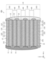
- FIG. 1 is a cross-sectional view of a battery according to Embodiment 1.
- FIG. 2A is a top view of the battery according to Embodiment 1.
- FIG. 2B is a bottom view of the battery according to Embodiment 1.
- FIG. 3A is a cross-sectional view of an example of a battery cell included in the power generation element according to Embodiment 1.
- FIG. 3B is a cross-sectional view of another example of a battery cell included in the power generation element according to Embodiment 1.
- FIG. 3C is a cross-sectional view of another example of a battery cell included in the power generation element according to Embodiment 1.
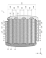
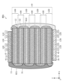
- FIG. 4 is a cross-sectional view of the power generating element according to Embodiment 1.
- FIG. 1 is a cross-sectional view of a battery according to Embodiment 1.
- FIG. 2A is a top view of the battery according to Embodiment 1.
- FIG. 2B is a bottom view of the battery
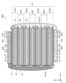
- FIG. 5 is a side view showing the positional relationship between the first side surface of the power generation element according to Embodiment 1 and the electrode insulating layer provided on the first side surface.
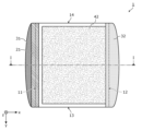
- FIG. 6 is a side view showing the positional relationship between the second side surface of the power generation element according to Embodiment 1 and the counter electrode insulating layer provided on the second side surface.
- FIG. 7 is a cross-sectional view of a battery according to Embodiment 2.
- FIG. 8 is a cross-sectional view of a battery according to Embodiment 3.
- FIG. 9 is a cross-sectional view of a battery according to Embodiment 4.
- FIG. 10 is a cross-sectional view of a battery according to Embodiment 5.
- FIG. 11A is a top view of a battery according to Embodiment 5.
- FIG. 11B is a bottom view of the battery according to Embodiment 5.
- FIG. 12 is a cross-sectional view of a battery according to Embodiment 6.
- FIG. 13 is a cross-sectional view of a battery according to Embodiment 7.
- FIG. 14 is a cross-sectional view of a battery according to Embodiment 8.
- FIG. FIG. 15 is a flow chart showing a method for manufacturing a battery according to the embodiment.
- a battery according to an aspect of the present disclosure has a plurality of battery cells each including an electrode layer, a counter electrode layer, and a solid electrolyte layer positioned between the electrode layer and the counter electrode layer, and the plurality of a power generating element in which battery cells are electrically connected in parallel and stacked; an electrode insulating member covering the electrode layer on a first side surface of the power generating element; an electrode insulating member covering the first side surface and the electrode insulating member; a counter electrode extracting portion electrically connected to a layer; a counter electrode insulating member covering the counter electrode layer on the second side surface of the power generating element; covering the second side surface and the counter electrode insulating member; a counter current collecting terminal provided on the first main surface of the power generating element; and an electrode provided on the second main surface opposite to the first main surface of the power generating element. and a collector terminal.
- the counter electrode extraction portion covers the first main surface and is connected to the counter electrode current collecting terminal, and the electrode extraction portion covers
- a high-performance battery can be realized.
- a battery with excellent reliability and large current characteristics can be realized.
- the electrode insulating member covers the electrode layer on the first side surface of the power generating element, it is possible to suppress the occurrence of a short circuit between the electrode layer and the counter electrode layer.
- the counter electrode insulating member covers the counter electrode layer, so it is possible to suppress the occurrence of a short circuit between the electrode layer and the counter electrode layer. Also, for example, by electrically connecting all the battery cells in parallel, it is possible to suppress overcharge or overdischarge of a specific battery cell due to variations in the capacity of each battery cell. In this way, the reliability of the battery can be enhanced.
- the counter electrode lead-out portion extends from the first side surface to the first main surface, the connection reliability of the counter electrode lead-out portion is enhanced. For example, since the portion covering the first main surface of the counter electrode extracting portion is caught on the power generating element, the counter electrode extracting portion is less likely to come off even when force is applied from the outside. The same applies to the electrode lead-out portion.
- the counter electrode current collecting terminal and the electrode current collecting terminal are provided on different main surfaces, for example, a large current collecting terminal can be formed so as to cover most of each main surface. Since the resistance of the current collecting terminal can be reduced, the large current characteristics can be improved.
- each of the plurality of battery cells includes a current collector, and the counter electrode current collector terminal and the electrode current collector terminal are more conductive than the current collector included in one of the plurality of battery cells. It can be expensive.
- the term "highly conductive" of the member does not mean that the resistivity inherent to the material constituting the member is low, but the value obtained by dividing the cross-sectional area perpendicular to the direction in which the current flows by the resistivity This means that is large.
- the conductivity of the member is determined by summing the values obtained by dividing the cross-sectional area of each of the plurality of materials by the corresponding resistivity.
- the counter electrode current collector terminal is a current collector forming the first main surface
- the thickness of the counter electrode current collector terminal is the thickness of the current collector included in one of the plurality of battery cells. It can be thicker.
- the number of parts can be reduced by using the counter electrode current collector as the counter electrode current collector terminal. Further, by making the counter electrode current collector used as the counter electrode current collector terminal thicker than the other current collectors, the resistance of the counter electrode current collector terminal can be easily reduced.
- the phrase "a collector terminal is provided on the main surface” means not only the case where a member different from the member constituting the main surface is arranged as the collector terminal on the main surface, It also means a case where the member itself constituting the main surface is a collector terminal.
- the electrode current collecting terminal is a current collector constituting the second main surface
- the thickness of the electrode current collecting terminal is the thickness of the current collector included in one of the plurality of battery cells. It can be thicker.
- the number of parts can be reduced by using the electrode current collector as an electrode current collecting terminal.
- the electrode current collector used as the electrode current collector thicker than other current collectors, it is possible to easily realize the low resistance of the electrode current collector terminal.
- an intermediate Further layers may be provided.
- the intermediate layer may be an insulating layer.
- the battery according to one aspect of the present disclosure may further include a conductive layer disposed on the first main surface and in contact with the counter electrode current collecting terminal and the counter electrode extraction portion.
- the conductive layer can be formed using a material suitable for electrical connection between the counter electrode extraction portion and the counter electrode current collecting terminal. Since the resistance at the connecting portion between the counter electrode lead-out portion and the counter electrode current collecting terminal can be reduced, the large current characteristics can be enhanced.
- the battery according to one aspect of the present disclosure may further include a conductive layer disposed on the second main surface and in contact with the electrode collector terminal and the electrode extraction portion.
- the conductive layer can be formed using a material suitable for electrical connection between the electrode extraction portion and the electrode collector terminal. Since the resistance at the connecting portion between the electrode lead-out portion and the electrode collector terminal can be reduced, the large current characteristics can be improved.
- the counter electrode layer may have a counter electrode current collector and a counter electrode active material layer positioned between the counter electrode current collector and the solid electrolyte layer.
- the counter electrode current collector protrudes from the counter electrode active material layer, and the counter electrode extraction part may be in contact with the main surface of the counter electrode current collector.
- the counter electrode extraction part contacts not only the end surface of the counter electrode current collector but also the main surface thereof, so that the contact area between the counter electrode extraction part and the counter electrode current collector is increased. Therefore, the connection resistance between the counter electrode lead-out portion and the counter electrode current collector is reduced, and the large current characteristics can be improved. For example, rapid charging of batteries becomes possible.
- the counter electrode active material layer may recede further than the electrode layer.
- the contact area between the counter electrode extracting portion and the counter electrode current collector can be further increased, so that the connection resistance between the counter electrode extracting portion and the counter electrode current collector can be further reduced.
- the end surface of the counter electrode current collector on the first side surface and the end surface of the electrode layer on the first side surface may coincide when viewed from a direction orthogonal to the main surface.
- a power generation element can be easily formed by collectively cutting a plurality of stacked battery cells.
- batch cutting for example, the areas of the electrode layer, the counter electrode layer and the solid electrolyte layer can be determined accurately without gradual increase or gradual decrease in film thickness at the coating start and end of each layer.
- the variation in the capacity of the battery cells is reduced, so the precision of the battery capacity can be improved.
- the electrode insulating member may cover at least a portion of the solid electrolyte layer on the first side surface.
- the electrode insulating member so as to partially cover the solid electrolyte layer, the electrode layer is exposed without being covered by the electrode insulating member even when there is variation in the size of the electrode insulating member. can be suppressed.
- the solid electrolyte layer is generally made of a powdery material, its end face has very fine unevenness. Therefore, the adhesion strength of the electrode insulating member is improved, and the insulation reliability is improved. In this way, the reliability of the battery can be further enhanced.
- the electrode insulating member may cover from the electrode layer to at least part of the counter electrode layer on the first side surface.
- the counter electrode layer by partially covering the counter electrode layer, it is possible to sufficiently prevent the electrode layer from being exposed without being covered by the electrode insulating member.
- the counter electrode active material layer is also generally formed of a powdery material, very fine irregularities are present on the end surface thereof. Therefore, the adhesion strength of the electrode insulating member is further improved, and the insulation reliability is improved. Therefore, the reliability of the battery can be further improved.
- the electrode insulating member covers the electrode layer of each of the plurality of battery cells on the first side surface, and the counter electrode extracting portion is electrically connected to the counter electrode layer of each of the plurality of battery cells. may be connected to
- the counter electrode extraction part can be used for parallel connection of a plurality of battery cells. Since the counter electrode extracting portion can be brought into close contact with the first side surface and the electrode insulating member, the volume of the portion involved in parallel connection can be reduced. Therefore, the energy density of the battery can be increased.
- the electrode insulating member may have a stripe shape in plan view of the first side surface.
- the end face of the electrode layer exposed in stripes on the first side surface can be effectively covered with the stripe-shaped electrode insulating member.
- the counter electrode insulating member covers the counter electrode layer of each of the plurality of battery cells on the second side surface, and the electrode extraction portion is electrically connected to the electrode layer of each of the plurality of battery cells. may be connected to
- the electrode extraction part can be used for parallel connection of multiple battery cells. Since the electrode lead-out portion can be brought into close contact with the second side surface and the counter electrode insulating member, the volume of the portion involved in parallel connection can be reduced. Therefore, the energy density of the battery can be increased.
- the counter electrode extracting portion may have a first conductive member that contacts the counter electrode layer and a second conductive member that covers the first conductive member.
- the counter electrode extracting portion can be formed using a plurality of materials with different properties.
- the material used for the first conductive member in contact with the counter electrode layer it is possible to select a material that has high electrical conductivity and is mainly alloyed with the metal contained in the current collector.
- the material used for the second conductive member can be selected with a focus on flexibility, impact resistance, chemical stability, cost, ease of spreading during construction, and the like. In this way, since materials suitable for each member can be selected, the performance of the battery can be improved and the ease of manufacturing the battery can be enhanced.
- the electrode insulating member or the counter electrode insulating member may contain resin.
- each of the counter electrode current collecting terminal and the electrode current collecting terminal is exposed, and the power generation element, the electrode extraction portion, and the counter electrode extraction portion are sealed. You may further provide the sealing member which stops.
- the power generation element can be protected from the outside air and water, so the reliability of the battery can be further improved.
- each figure is a schematic diagram and is not necessarily strictly illustrated. Therefore, for example, scales and the like do not necessarily match in each drawing. Moreover, in each figure, substantially the same configurations are denoted by the same reference numerals, and overlapping descriptions are omitted or simplified.
- the x-axis, y-axis and z-axis indicate three axes of a three-dimensional orthogonal coordinate system.
- the x-axis and the y-axis respectively correspond to the directions parallel to the first side of the rectangle and the second side orthogonal to the first side when the power generating element of the battery has a rectangular plan view shape.
- the z-axis coincides with the stacking direction of the plurality of battery cells included in the power generation element.
- the "stacking direction” corresponds to the direction normal to the main surfaces of the current collector and the active material layer.
- plan view means when viewed from a direction perpendicular to the main surface of the power generation element, unless otherwise specified, such as when the power generation element is used alone. It should be noted that when “plan view of a certain surface” is described, such as “plan view of the first side surface”, it means when the “certain surface” is viewed from the front.
- the terms “upper” and “lower” do not refer to the upward direction (vertically upward) and the downward direction (vertically downward) in absolute spatial recognition, but are based on the stacking order in the stacking structure. It is used as a term defined by a relative positional relationship. Also, the terms “above” and “below” are used only when two components are spaced apart from each other and there is another component between them, as well as when two components are spaced apart from each other. It also applies when two components are in contact with each other and are placed in close contact with each other. In the following description, the negative side of the z-axis is called “lower” or “lower”, and the positive side of the z-axis is called “upper” or “upper”.
- the expression “covering A” means covering at least part of “A”. That is, the expression “covering A” includes not only the case of “covering all of A” but also the case of “covering only a part of A.”
- “A” is, for example, the side surface and main surface of a given member such as a layer or terminal.
- ordinal numbers such as “first” and “second” do not mean the number or order of constituent elements unless otherwise specified. It is used for the purpose of distinguishing elements.
- Embodiment 1 The configuration of the battery according to Embodiment 1 will be described below.
- FIG. 1 is a cross-sectional view of battery 1 according to the present embodiment.
- the battery 1 includes a power generating element 10, an electrode insulating layer 21, a counter electrode insulating layer 22, a counter electrode extraction portion 31, an electrode extraction portion 32, a counter electrode collector terminal 41, an electrode collector It includes an electrode terminal 42 , a counter electrode intermediate layer 51 and an electrode intermediate layer 52 .
- the battery 1 is, for example, an all-solid battery.
- FIG. 2A is a top view of battery 1 according to the present embodiment.
- FIG. 2B is a bottom view of battery 1 according to the present embodiment. Note that FIG. 1 shows a cross section taken along line II of FIGS. 2A and 2B.
- the plan view shape of the power generation element 10 is, for example, rectangular as shown in FIGS. 2A and 2B. That is, the shape of the power generation element 10 is a flat rectangular parallelepiped.
- flat means that the thickness (that is, the length in the z-axis direction) is shorter than each side (that is, each length in the x-axis direction and the y-axis direction) or the maximum width of the main surface.
- the plan view shape of the power generation element 10 may be a square, a hexagon, an octagon, or another polygon, or may be a circle, an ellipse, or the like. Note that in cross-sectional views such as FIG. 1 , the thickness of each layer is exaggerated in order to facilitate understanding of the layer structure of the power generation element 10 .
- the power generation element 10 includes four side surfaces 11, 12, 13 and 14 and two main surfaces 15 and 16, as shown in FIGS. 1, 2A and 2B.
- the side surfaces 11, 12, 13 and 14 and the main surfaces 15 and 16 are all flat surfaces.
- the side 11 is an example of the first side.
- Side 12 is an example of a second side.
- Sides 11 and 12 face away from each other and are parallel to each other.
- Sides 13 and 14 face away from each other and are parallel to each other.
- the side surfaces 11, 12, 13 and 14 are cut surfaces formed by collectively cutting a stack of a plurality of battery cells 100, for example.
- the main surfaces 15 and 16 face each other and are parallel to each other.
- the main surface 15 is the top surface of the power generation element 10 .
- the main surface 16 is the bottom surface of the power generation element 10 .
- Major surfaces 15 and 16 are each larger in area than side surfaces 11, 12, 13 and 14, respectively.
- the power generation element 10 has multiple battery cells 100 .
- the battery cell 100 is a battery with a minimum configuration and is also called a unit cell.
- a plurality of battery cells 100 are electrically connected in parallel and stacked. In this embodiment, all the battery cells 100 included in the power generation element 10 are electrically connected in parallel.
- the number of battery cells 100 included in the power generation element 10 is seven, but the number is not limited to this.
- the number of battery cells 100 included in the power generation element 10 may be an even number such as two or four, or an odd number such as three or five.
- Each of the plurality of battery cells 100 includes an electrode layer 110, a counter electrode layer 120, and a solid electrolyte layer 130.
- the electrode layer 110 has an electrode current collector 111 and an electrode active material layer 112 .
- the counter electrode layer 120 has a counter electrode current collector 121 and a counter electrode active material layer 122 .
- an electrode current collector 111, an electrode active material layer 112, a solid electrolyte layer 130, a counter electrode active material layer 122 and a counter electrode current collector 121 are laminated in this order along the z-axis. .
- the electrode layer 110 is one of the positive electrode layer and the negative electrode layer of the battery cell 100 .
- the counter electrode layer 120 is the other of the positive electrode layer and the negative electrode layer of the battery cell 100 .
- the electrode layer 110 is a negative electrode layer and the counter electrode layer 120 is a positive electrode layer.
- the configurations of the plurality of battery cells 100 are substantially the same. In two battery cells 100 adjacent to each other, the order of arrangement of each layer constituting the battery cell 100 is reversed. That is, the plurality of battery cells 100 are stacked side by side along the z-axis while the order of the layers constituting the battery cells 100 alternates. In the present embodiment, since the number of battery cells 100 is an odd number, the bottom layer and the top layer of power generation element 10 are current collectors of different polarities, respectively.
- FIG. 3A is a cross-sectional view of battery cell 100 included in power generation element 10 according to the present embodiment.
- the electrode current collector 111 and the counter electrode current collector 121 are conductive foil-shaped, plate-shaped, or mesh-shaped members, respectively. Each of the electrode current collector 111 and the counter electrode current collector 121 may be, for example, a conductive thin film. As materials for forming the electrode current collector 111 and the counter electrode current collector 121, for example, metals such as stainless steel (SUS), aluminum (Al), copper (Cu), and nickel (Ni) can be used. The electrode current collector 111 and the counter electrode current collector 121 may be formed using different materials.
- each of the electrode current collector 111 and the counter electrode current collector 121 is, for example, 5 ⁇ m or more and 100 ⁇ m or less, but is not limited to this.
- An electrode active material layer 112 is in contact with the main surface of the electrode current collector 111 .
- the electrode current collector 111 may include a current collector layer, which is a layer containing a conductive material and provided in a portion in contact with the electrode active material layer 112 .
- a counter electrode active material layer 122 is in contact with the main surface of the counter electrode current collector 121 .
- the counter electrode current collector 121 may include a current collector layer, which is a layer containing a conductive material and provided in a portion in contact with the counter electrode active material layer 122 .
- the electrode active material layer 112 is arranged on the main surface of the electrode current collector 111 on the counter electrode layer 120 side.
- the electrode active material layer 112 contains, for example, a negative electrode active material as an electrode material.
- the electrode active material layer 112 is arranged to face the counter electrode active material layer 122 .
- a negative electrode active material such as graphite or metallic lithium can be used.
- Various materials capable of extracting and inserting ions such as lithium (Li) or magnesium (Mg) may be used as materials of the negative electrode active material.
- a solid electrolyte such as an inorganic solid electrolyte may be used.
- an inorganic solid electrolyte for example, a sulfide solid electrolyte or an oxide solid electrolyte can be used.
- a sulfide solid electrolyte for example, a mixture of lithium sulfide (Li 2 S) and phosphorus pentasulfide (P 2 S 5 ) can be used.
- a conductive material such as acetylene black or a binding binder such as polyvinylidene fluoride may be used.
- the electrode active material layer 112 is produced by coating the main surface of the electrode current collector 111 with a paste-like paint in which the material contained in the electrode active material layer 112 is kneaded together with a solvent and drying it.
- the electrode layer 110 also referred to as an electrode plate
- the thickness of the electrode active material layer 112 is, for example, 5 ⁇ m or more and 300 ⁇ m or less, but is not limited thereto.
- the counter electrode active material layer 122 is arranged on the main surface of the counter electrode current collector 121 on the electrode layer 110 side.
- the counter electrode active material layer 122 is a layer containing a positive electrode material such as an active material.
- the positive electrode material is the material that constitutes the counter electrode of the negative electrode material.
- the counter electrode active material layer 122 contains, for example, a positive electrode active material.
- Examples of the positive electrode active material contained in the counter electrode active material layer 122 include lithium cobaltate composite oxide (LCO), lithium nickelate composite oxide (LNO), lithium manganate composite oxide (LMO), and lithium-manganese.
- LCO lithium cobaltate composite oxide
- LNO lithium nickelate composite oxide
- LMO lithium manganate composite oxide
- LNMCO lithium-manganese
- LMNO nickel composite oxide
- LMCO lithium-manganese-cobalt composite oxide
- LNCO lithium-nickel-cobalt composite oxide
- LNMCO lithium-nickel-manganese-cobalt composite oxide
- Various materials capable of withdrawing and inserting ions such as Li or Mg can be used as the material of the positive electrode active material.
- a solid electrolyte such as an inorganic solid electrolyte may be used.
- a sulfide solid electrolyte, an oxide solid electrolyte, or the like can be used.
- a sulfide solid electrolyte for example, a mixture of Li2S and P2S5 can be used.
- the surface of the positive electrode active material may be coated with a solid electrolyte.
- a conductive material such as acetylene black or a binding binder such as polyvinylidene fluoride may be used.
- the counter electrode active material layer 122 is produced by applying a paste-like paint in which the material contained in the counter electrode active material layer 122 is kneaded together with a solvent onto the main surface of the counter electrode current collector 121 and drying it.
- the counter electrode layer 120 also referred to as a counter electrode plate
- the thickness of the counter electrode active material layer 122 is, for example, 5 ⁇ m or more and 300 ⁇ m or less, but is not limited thereto.
- the solid electrolyte layer 130 is arranged between the electrode active material layer 112 and the counter electrode active material layer 122 . Solid electrolyte layer 130 is in contact with each of electrode active material layer 112 and counter electrode active material layer 122 .
- Solid electrolyte layer 130 is a layer containing an electrolyte material. As the electrolyte material, generally known battery electrolytes can be used. The thickness of solid electrolyte layer 130 may be 5 ⁇ m or more and 300 ⁇ m or less, or may be 5 ⁇ m or more and 100 ⁇ m or less.
- Solid electrolyte layer 130 contains a solid electrolyte.
- a solid electrolyte such as an inorganic solid electrolyte can be used.
- an inorganic solid electrolyte a sulfide solid electrolyte, an oxide solid electrolyte, or the like can be used.
- a sulfide solid electrolyte for example, a mixture of Li2S and P2S5 can be used.
- the solid electrolyte layer 130 may contain a binding binder such as polyvinylidene fluoride.
- the electrode active material layer 112, the counter electrode active material layer 122, and the solid electrolyte layer 130 are maintained in the form of parallel plates. As a result, it is possible to suppress the occurrence of cracks or collapse due to bending. Note that the electrode active material layer 112, the counter electrode active material layer 122, and the solid electrolyte layer 130 may be combined and smoothly curved.
- the end surface of the counter electrode layer 120 on the side surface 11 side and the end surface of the electrode layer 110 on the side surface 11 side coincide when viewed from the z-axis direction.
- the end surface of the counter electrode current collector 121 on the side surface 11 side and the end surface of the electrode current collector 111 on the side surface 11 side match when viewed from the z-axis direction. The same applies to the end surfaces of the counter electrode current collector 121 and the electrode current collector 111 on the side surface 12 side.
- electrode current collector 111 electrode active material layer 112, solid electrolyte layer 130, counter electrode active material layer 122, and counter electrode current collector 121 have the same shape and size. , the contours of each match. That is, the shape of the battery cell 100 is a flat rectangular parallelepiped shape.
- two adjacent battery cells 100 share a current collector.
- the battery cell 100 in the bottom layer and the battery cell 100 one above it share one electrode current collector 111 .
- Electrode active material layers 112 are provided on both main surfaces of a shared electrode current collector 111 .
- Two counter electrode layers 120 adjacent to each other share the counter electrode current collector 121 with each other.
- a counter electrode active material layer 122 is provided on both main surfaces of a shared counter electrode current collector 121 .
- Such a battery 1 is formed by combining and stacking not only the battery cell 100 shown in FIG. 3A, but also the battery cells 100B and 100C shown in FIGS. 3B and 3C.
- the battery cell 100 shown in FIG. 3A will be described as a battery cell 100A.
- a battery cell 100B shown in FIG. 3B has a configuration in which the electrode current collector 111 is removed from the battery cell 100A shown in FIG. 3A. That is, the electrode layer 110B of the battery cell 100B consists of the electrode active material layer 112 only.
- a battery cell 100C shown in FIG. 3C has a configuration in which the counter electrode current collector 121 is removed from the battery cell 100A shown in FIG. 3A. That is, the counter electrode layer 120C of the battery cell 100C consists of only the counter electrode active material layer 122. As shown in FIG.
- FIG. 4 is a cross-sectional view showing the power generating element 10 according to this embodiment.
- FIG. 4 is a diagram extracting only the power generation element 10 of FIG.
- the battery cell 100A is arranged in the bottom layer, and the battery cells 100B and 100C are alternately stacked upward. At this time, the battery cell 100A and the battery cell 100B are each stacked upside down from the direction illustrated in FIG. 3A or 3B. Thereby, the power generation element 10 is formed.
- the method of forming the power generation element 10 is not limited to this.
- the battery cell 100A may be arranged in the uppermost layer.
- the battery cell 100A may be arranged at a position different from both the top layer and the bottom layer.
- a plurality of battery cells 100A may be used.
- a unit of two battery cells 100 sharing a current collector may be formed by coating both sides of one current collector, and the formed units may be stacked.
- the power generation element 10 As described above, in the power generation element 10 according to the present embodiment, all the battery cells 100 are connected in parallel, and no battery cells connected in series are included. Therefore, when the battery 1 is charged and discharged, non-uniform charging and discharging due to variations in the capacity of the battery cells 100 are less likely to occur. Therefore, the possibility that some of the plurality of battery cells 100 are overcharged or overdischarged can be greatly reduced, and the reliability of the battery 1 can be improved.
- the electrode insulating layer 21 is an example of an electrode insulating member, and covers the electrode layer 110 on the side surface 11 as shown in FIG. Specifically, the electrode insulating layer 21 completely covers the electrode current collector 111 and the electrode active material layer 112 on the side surface 11 .
- FIG. 5 is a side view showing the positional relationship between the side surface 11 of the power generating element 10 and the electrode insulating layer 21 provided on the side surface 11 according to this embodiment.
- the end face of each layer appearing on the side surface 11 is shaded in the same manner as the layers shown in the cross section of FIG. 1 . This also applies to FIG. 6, which will be described later.
- FIG. 5 is a side view of the power generation element 10, and is a plan view of the side surface 11 viewed from the front.
- (b) of FIG. 5 shows the side surface 11 of (a) of FIG. 5 and the electrode insulating layer 21 provided on the side surface 11 .
- FIG. 5B is a side view of the battery 1 of FIG. 1 viewed from the negative side of the x-axis through the counter electrode extracting portion 31 .
- the electrode insulating layer 21 covers the electrode layer 110 of each of the plurality of battery cells 100 on the side surface 11 .
- the electrode insulating layer 21 does not cover at least part of the counter electrode layer 120 of each of the plurality of battery cells 100 .
- the electrode insulating layer 21 does not cover the counter electrode current collector 121 . Therefore, the electrode insulating layer 21 has a striped shape in plan view of the side surface 11 .
- the electrode insulating layer 21 continuously covers the electrode layers 110 of the two adjacent battery cells 100 . Specifically, the electrode insulating layer 21 extends from at least a portion of one solid electrolyte layer 130 of two adjacent battery cells 100 to at least a portion of the other solid electrolyte layer 130 of two adjacent battery cells 100. are continuously covered.
- the electrode insulating layer 21 covers at least part of the solid electrolyte layer 130 on the side surface 11 . Specifically, when the side surface 11 is viewed in plan, the contour of the electrode insulating layer 21 overlaps the solid electrolyte layer 130 . As a result, even if the width (the length in the z-axis direction) varies due to manufacturing variations in the electrode insulating layer 21, the possibility of exposing the electrode layer 110 is reduced. Therefore, short-circuiting between the electrode layer 110 and the counter electrode layer 120 via the counter electrode lead-out portion 31 formed to cover the electrode insulating layer 21 can be suppressed. Further, the end surface of the solid electrolyte layer 130 made of a powdery material has very fine unevenness. For this reason, the electrode insulating layer 21 enters into the irregularities, thereby improving the adhesion strength of the electrode insulating layer 21 and improving the insulation reliability.
- electrode insulating layer 21 may cover all of solid electrolyte layer 130 on side surface 11 . Specifically, the contour of the electrode insulating layer 21 may overlap the boundary between the solid electrolyte layer 130 and the counter electrode active material layer 122 . It should be noted that it is not essential that the electrode insulating layer 21 partially cover the solid electrolyte layer 130 . For example, the contour of the electrode insulating layer 21 may overlap the boundary between the solid electrolyte layer 130 and the electrode active material layer 112 .
- the electrode insulating layer 21 is provided separately for each electrode layer 110 in FIG. 5(b), the present invention is not limited to this.
- the electrode insulating layer 21 may be provided along the z-axis direction at the end of the side surface 11 in the y-axis direction, in addition to the stripe-shaped portion.
- the shape of the electrode insulating layer 21 may be a ladder shape in a plan view of the side surface 11 .
- the electrode insulating layer 21 may partially cover the counter electrode current collector 121 .
- the electrode current collector 111 is the bottom layer. As shown in FIGS. 1 and 5B, near the upper end of the side surface 11, the electrode insulating layer 21 partially covers the main surface of the electrode current collector 111 positioned at the bottom layer. As a result, the electrode insulating layer 21 is strong against an external force in the z-axis direction, and detachment is suppressed. Further, even when the counter electrode lead-out portion 31 wraps around the main surface 16 of the power generating element 10, it can be prevented from coming into contact with the electrode current collector 111 and causing a short circuit. Thus, the reliability of battery 1 can be enhanced.
- the counter electrode insulating layer 22 is an example of a counter electrode insulating member, and covers the counter electrode layer 120 on the side surface 12 as shown in FIG. Specifically, counter electrode insulating layer 22 completely covers counter electrode current collector 121 and counter electrode active material layer 122 on side surface 12 .
- FIG. 6 is a side view showing the positional relationship between the side surface 12 of the power generation element 10 and the counter electrode insulating layer 22 provided on the side surface 12 according to the present embodiment.
- FIG. 6(a) is a side view of the power generation element 10, and is a plan view of the side 12 viewed from the front.
- (b) of FIG. 6 shows the side surface 12 of (a) of FIG. 6 and the counter electrode insulating layer 22 provided on the side surface 12 . That is, FIG. 6(b) is a side view of the battery 1 of FIG.
- the counter electrode insulating layer 22 covers the counter electrode layer 120 of each of the plurality of battery cells 100 on the side surface 12 .
- the counter electrode insulating layer 22 does not cover at least part of each electrode layer 110 of the plurality of battery cells 100 .
- the counter electrode insulating layer 22 does not cover the electrode current collector 111 . Therefore, the counter electrode insulating layer 22 has a striped shape in plan view of the side surface 12 .
- the counter electrode insulating layer 22 continuously covers the counter electrode layers 120 of the two adjacent battery cells 100 .
- the counter electrode insulating layer 22 extends from at least a portion of one solid electrolyte layer 130 of two adjacent battery cells 100 to at least a portion of the other solid electrolyte layer 130 of two adjacent battery cells 100. are continuously covered.
- the counter electrode insulating layer 22 covers at least part of the solid electrolyte layer 130 on the side surface 12 .
- the outline of the counter electrode insulating layer 22 overlaps the solid electrolyte layer 130 when the side surface 12 is viewed in plan.
- the width the length in the z-axis direction
- the possibility of exposing the counter electrode layer 120 is reduced. Therefore, short-circuiting between the counter electrode layer 120 and the electrode layer 110 via the electrode lead-out portion 32 formed to cover the counter electrode insulating layer 22 can be suppressed.
- the counter electrode insulating layer 22 enters the unevenness of the end surface of the solid electrolyte layer 130, the adhesion strength of the counter electrode insulating layer 22 is improved, and the insulation reliability is improved.
- the counter electrode insulating layer 22 may cover the entire solid electrolyte layer 130 on the side surface 12 .
- the contour of the counter electrode insulating layer 22 may overlap the boundary between the solid electrolyte layer 130 and the electrode active material layer 112 .
- the contour of the counter electrode insulating layer 22 may overlap the boundary between the solid electrolyte layer 130 and the counter electrode active material layer 122 .
- the counter electrode insulating layer 22 is provided separately for each counter electrode layer 120 in FIG. 6(b), the present invention is not limited to this.
- the counter electrode insulating layer 22 may be provided along the z-axis direction at the end of the side surface 12 in the y-axis direction, in addition to the stripe-shaped portion.
- the shape of the counter electrode insulating layer 22 may be a ladder shape in a plan view of the side surface 12 .
- the counter electrode insulating layer 22 may partially cover the electrode current collector 111 .
- the uppermost layer is the counter electrode current collector 121 .
- the counter electrode insulating layer 22 partially covers the main surface of the counter electrode current collector 121 located on the uppermost layer.
- the counter electrode insulating layer 22 is strong against an external force in the z-axis direction, and detachment is suppressed.
- the electrode lead-out portion 32 wraps around the main surface 15 of the power generating element 10, it can be prevented from coming into contact with the counter electrode current collector 121 and causing a short circuit.
- the reliability of battery 1 can be enhanced.
- the electrode insulating layer 21 and the counter electrode insulating layer 22 are each formed using an electrically insulating insulating material.
- the electrode insulating layer 21 and the counter electrode insulating layer 22 each contain resin.
- the resin is, for example, an epoxy resin, but is not limited to this.
- An inorganic material may be used as the insulating material. Usable insulating materials are selected based on various properties such as flexibility, gas barrier properties, impact resistance, and heat resistance.
- the electrode insulating layer 21 and the counter electrode insulating layer 22 are formed using the same material, but may be formed using different materials.
- the counter electrode extracting portion 31 is a conductive portion that covers the side surface 11 and the electrode insulating layer 21 and is electrically connected to the counter electrode layer 120, as shown in FIG. Specifically, the counter electrode extracting portion 31 covers the electrode insulating layer 21 and the portion of the side surface 11 that is not covered with the electrode insulating layer 21 .
- the end surfaces of the counter electrode current collector 121 and the counter electrode active material layer 122 are exposed on the portion of the side surface 11 not covered with the electrode insulating layer 21 . Therefore, the counter electrode extracting portion 31 is in contact with the respective end surfaces of the counter electrode current collector 121 and the counter electrode active material layer 122 and is electrically connected to the counter electrode layer 120 . Since the counter electrode active material layer 122 is made of a powdery material, it has very fine irregularities like the solid electrolyte layer 130 . By inserting the counter electrode extraction part 31 into the unevenness of the end surface of the counter electrode active material layer 122, the adhesion strength of the counter electrode extraction part 31 is improved, and the reliability of electrical connection is improved.
- the counter electrode extraction part 31 is electrically connected to the counter electrode layer 120 of each of the plurality of battery cells 100 . That is, the counter electrode extracting portion 31 has a function of electrically connecting the battery cells 100 in parallel. As shown in FIG. 1 , the counter electrode extracting portion 31 covers substantially the entire side surface 11 from the lower end to the upper end.
- the uppermost layer is the counter electrode current collector 121 .
- the counter electrode extracting portion 31 covers a portion of the main surface of the counter electrode current collector 121 located in the uppermost layer, that is, the main surface 15 of the power generation element 10 . .
- the counter electrode extracting portion 31 is strong against an external force in the z-axis direction, and detachment is suppressed.
- the contact area between the counter electrode extracting portion 31 and the counter electrode current collector 121 is increased, the connection resistance between the counter electrode extracting portion 31 and the counter electrode current collector 121 is reduced, and large current characteristics can be improved. For example, rapid charging of the battery 1 becomes possible.
- the electrode lead-out portion 32 is a conductive portion that covers the side surface 12 and the counter electrode insulating layer 22 and is electrically connected to the electrode layer 110, as shown in FIG. Specifically, the electrode lead-out portion 32 covers the counter electrode insulating layer 22 and the portion of the side surface 12 that is not covered with the counter electrode insulating layer 22 .
- the electrode lead-out portion 32 is in contact with the end surfaces of the electrode current collector 111 and the electrode active material layer 112 and is electrically connected to the electrode layer 110 . Since the electrode active material layer 112 is made of a powdery material, it has very fine irregularities like the solid electrolyte layer 130 . Since the electrode lead-out portion 32 enters the unevenness of the end face of the electrode active material layer 112, the adhesion strength of the electrode lead-out portion 32 is improved, and the reliability of electrical connection is improved.
- the electrode extraction part 32 is electrically connected to the electrode layer 110 of each of the plurality of battery cells 100 . That is, the electrode extracting portion 32 has a function of electrically connecting the battery cells 100 in parallel. As shown in FIG. 1, the electrode lead-out portion 32 covers substantially the entire side surface 12 from the lower end to the upper end.
- the electrode current collector 111 is the bottom layer. As shown in FIG. 1 , at the lower end of the side surface 12 , the electrode lead-out portion 32 covers a portion of the main surface of the electrode current collector 111 located in the lowest layer, that is, the main surface 16 of the power generation element 10 . . As a result, the electrode lead-out portion 32 is strong against an external force in the z-axis direction, and detachment is suppressed. In addition, since the contact area between the electrode extraction portion 32 and the electrode current collector 111 is increased, the connection resistance between the electrode extraction portion 32 and the electrode current collector 111 is reduced, and large current characteristics can be improved. For example, rapid charging of the battery 1 becomes possible.
- the counter electrode extracting portion 31 and the electrode extracting portion 32 are formed using a conductive resin material or the like. Alternatively, the counter electrode extracting portion 31 and the electrode extracting portion 32 may be formed using a metal material such as solder. Conductive materials that can be used are selected based on various properties such as flexibility, gas barrier properties, impact resistance, heat resistance, and solder wettability. The counter electrode extracting portion 31 and the electrode extracting portion 32 are formed using the same material, but may be formed using different materials.
- the counter electrode collector terminal 41 is a conductive terminal connected to the counter electrode extracting portion 31 .
- the counter electrode current collecting terminal 41 is one of the external connection terminals of the battery 1, and is a positive electrode extraction terminal in the present embodiment. As shown in FIG. 1 , the counter electrode collector terminal 41 is arranged on the main surface 15 of the power generating element 10 with the counter electrode intermediate layer 51 interposed therebetween.
- the counter current collector terminal 41 is arranged apart from the side surface 11 in plan view of the main surface 15 . That is, the counter electrode lead-out portion 31 is provided so as to cover the region between the side surface 11 and the counter electrode collector terminal 41 in the main surface 15 .
- the counter electrode extracting portion 31 continuously covers from the side surface 11 to the main surface 15 and is connected to a counter electrode collector terminal 41 .
- the height of the counter electrode extracting portion 31 from the main surface 15 is equal to or less than the height of the counter electrode collector terminal 41 from the main surface 15 . That is, the counter electrode extracting portion 31 is in contact with the end face of the counter electrode collector terminal 41 so as not to cover the upper surface of the counter electrode collector terminal 41 . Since the upper surface of the counter electrode collector terminal 41 is the uppermost surface of the battery 1 , connection to the counter electrode collector terminal 41 can be easily performed when the battery 1 is mounted.
- the electrode collector terminal 42 is a conductive terminal connected to the electrode extraction portion 32 .
- the electrode collector terminal 42 is one of the external connection terminals of the battery 1, and in this embodiment, it is a negative electrode extraction terminal. As shown in FIG. 1 , the electrode collector terminal 42 is arranged on the main surface 16 of the power generation element 10 with the electrode intermediate layer 52 interposed therebetween.
- the electrode collector terminal 42 is arranged apart from the side surface 12 in plan view of the principal surface 16 . That is, the electrode lead-out portion 32 is provided so as to cover the area between the side surface 12 and the electrode collector terminal 42 on the main surface 16 .
- the electrode lead-out portion 32 continuously covers from the side surface 12 to the main surface 16 and is connected to the electrode collector terminal 42 .
- the height of the electrode lead-out portion 32 from the main surface 16 is equal to or less than the height of the electrode collector terminal 42 from the main surface 16 . That is, the electrode lead-out portion 32 is in contact with the end surface of the electrode current collecting terminal 42 so as not to cover the lower surface of the electrode current collecting terminal 42 . Since the bottom surface of the electrode current collecting terminal 42 is the bottom surface of the battery 1 , connection to the electrode current collecting terminal 42 can be easily performed when the battery 1 is mounted.
- the counter electrode current collecting terminal 41 and the electrode current collecting terminal 42 are provided on the main surfaces 15 and 16 of the power generating element 10, which are different from each other. Since the two terminals with different polarities are arranged apart, it is possible to suppress the occurrence of a short circuit.
- the counter electrode collector terminal 41 has higher conductivity than the counter electrode collector 121 .
- the thickness (the length in the z-axis direction) of the counter electrode collector terminal 41 is thicker than the thickness of the counter electrode collector 121 .
- the counter electrode current collector terminal 41 is provided so as to occupy more than half of the main surface 15 .
- the length of the counter electrode current collector terminal 41 (that is, the length in the x-axis direction) is at least half the length of the side surfaces 13 and 14 (that is, the length in the x-axis direction).
- the width (that is, the length in the y-axis direction) of the counter electrode current collector terminal 41 is half or more of the width (that is, the length in the y-axis direction) of the side surface 11 .
- the width of the counter electrode collector terminal 41 can be made equal to the width of the counter electrode lead-out portion 31 (that is, the length in the y-axis direction).
- the contact area with the conductive portion of the mounting substrate can be increased, and the contact resistance can be increased. can be lowered. Also from this point, it is effective for taking out a large current.
- the electrode collector terminal 42 has higher conductivity than the electrode collector 111 .
- the thickness (the length in the z-axis direction) of the electrode collector terminal 42 is thicker than the thickness of the electrode collector 111 .
- the electrode current collecting terminal 42 is provided so as to occupy more than half of the main surface 16 .
- the length of the electrode current collecting terminal 42 (that is, the length in the x-axis direction) is half or more the length of the side surfaces 13 and 14 (that is, the length in the x-axis direction).
- the width (that is, the length in the y-axis direction) of the electrode current collecting terminal 42 is half or more of the width (that is, the length in the y-axis direction) of the side surface 12 .
- the width of the electrode collector terminal 42 can be made equal to the width of the electrode lead-out portion 32 (that is, the length in the y-axis direction).
- the width in the direction in which the current flows from the electrode lead-out portion 32 to the electrode collector terminal 42 can be widened, so that the resistance can be reduced, which is effective in extracting a large current.
- the contact area with the conductive portion of the mounting substrate can be increased, and the contact resistance can be increased. can be lowered. Also from this point, it is effective for taking out a large current.
- the counter electrode collector terminal 41 and the electrode collector terminal 42 are each formed using a material having conductivity.
- the counter electrode collector terminal 41 and the electrode collector terminal 42 are metal foils or metal plates made of metal such as copper, aluminum, and stainless steel.
- the counter electrode current collecting terminal 41 and the electrode current collecting terminal 42 may be hardened solder.
- the counter electrode intermediate layer 51 is arranged between the counter electrode collector terminal 41 and the main surface 15 .
- main surface 15 is the main surface of counter electrode current collector 121 , insulation between counter electrode current collector terminal 41 and main surface 15 need not be ensured. Therefore, the counter electrode intermediate layer 51 may be a conductive layer. Further, counter electrode intermediate layer 51 may not be provided.
- the electrode intermediate layer 52 is arranged between the electrode collector terminal 42 and the main surface 16 .
- the electrode intermediate layer 52 may be a conductive layer. Also, the electrode intermediate layer 52 may not be provided.
- the plan view shape and size of the counter electrode intermediate layer 51 are the same as those of the counter electrode collector terminal 41, but are not limited to this.
- the counter electrode intermediate layer 51 may be larger or smaller than the counter electrode collector terminal 41 in plan view.
- the counter electrode intermediate layer 51 may cover the entire main surface 15 .
- the planar view shape and size of the electrode intermediate layer 52 are the same as those of the electrode collector terminal 42, but are not limited to this.
- the electrode intermediate layer 52 may be larger or smaller than the electrode collector terminal 42 in plan view.
- the electrode intermediate layer 52 may cover the entire major surface 16 .
- the counter electrode intermediate layer 51 and the electrode intermediate layer 52 are formed using, for example, an electrically insulating material.
- the counter electrode intermediate layer 51 and the electrode intermediate layer 52 each contain a resin.
- the resin is, for example, an epoxy resin, but is not limited to this.
- An inorganic material may be used as the insulating material.
- Counter electrode intermediate layer 51 and electrode intermediate layer 52 are formed using the same material, but may be formed using different materials. When the counter electrode intermediate layer 51 and the electrode intermediate layer 52 are conductive layers, they can be formed using a metal, a conductive resin, or the like.
- the arrangement of the counter electrode collector terminal 41 and the electrode collector terminal 42 may be reversed. That is, the counter electrode collector terminal 41 may be arranged on the main surface 16 and the electrode collector terminal 42 may be arranged on the main surface 15 .
- the main surface 16 is the main surface of the electrode current collector 111
- a counter electrode intermediate layer 51 made of an insulating layer is arranged.
- main surface 15 is the main surface of counter electrode current collector 121
- an electrode intermediate layer 52 made of an insulating layer is arranged.
- the counter electrode intermediate layer 51 and the electrode intermediate layer 52 may have additional functions such as impact resistance, rust prevention, and waterproofing in addition to ensuring insulation. Materials suitable for these functions can be used for the counter electrode intermediate layer 51 and the electrode intermediate layer 52 .
- the counter electrode intermediate layer 51 and the electrode intermediate layer 52 may each have a laminated structure of different materials.
- the counter electrode current collecting terminal 41 is provided on the main surface 15 of the power generating element 10, and the electrode current collecting terminal 42 is provided on the main surface 16 opposite to the main surface 15. is provided. That is, both the positive and negative terminals required for extracting current from the power generation element 10 are provided on the main surfaces 15 and 16 that are different from each other. This allows, for example, terminals with different polarities to be spaced apart, thereby reducing the possibility of a short circuit.
- the main surfaces 15 and 16 are larger in area than the side surfaces 11, 12, 13 and 14. Since the surface with a large area can be used as an external connection terminal, the battery 1 can be mounted over a large area, and connection reliability can be improved. In addition, since the shape and arrangement of the external connection terminals can be adjusted according to the wiring layout of the board to be mounted, the degree of freedom in connection can be increased.
- the counter electrode extracting portion 31 and the electrode extracting portion 32 each have a function of connecting the plurality of battery cells 100 in parallel.
- the counter electrode extracting portion 31 and the electrode extracting portion 32 are formed so as to closely cover the side surfaces 11 and 12 of the power generating element 10, respectively, so that their volumes can be reduced.
- the volume of the lead-out portion is smaller than that of a conventional current collecting tab electrode, so that the energy density per unit volume of the battery 1 can be improved.
- the counter electrode current collector terminal 41 which is a member different from the counter electrode current collector 121 located in the uppermost layer, is provided via the counter electrode intermediate layer 51, which is an insulating layer, the uppermost counter electrode current collector 121 It is possible to suppress the concentration of current to When current concentration occurs on the counter electrode current collector 121, the temperature rise due to the heat generated by the current may cause the counter electrode current collector 121 to peel off and accelerate the deterioration of the uppermost battery cell 100. be.
- the counter electrode extracting portion 31 and the counter electrode current collecting terminal 41 as well as the electrode extracting portion 32 and the electrode current collecting terminal 42 are used as the current path from each battery cell 100 . Therefore, current concentration on the uppermost counter electrode current collector 121 can be suppressed, and the reliability of the battery 1 can be improved. The same can be said for the electrode collector terminal 42 and the electrode intermediate layer 52 in the lowermost layer.
- the counter electrode current collector in the uppermost layer is used as the counter electrode current collector terminal
- the electrode current collector in the lowermost layer is used as the electrode current collector terminal.
- the point of use is different. The following description focuses on the differences from the battery according to Embodiment 1, and omits or simplifies the description of the common points.
- FIG. 7 is a cross-sectional view of battery 201 according to the present embodiment.
- battery 201 instead of counter electrode collector terminal 41, electrode collector terminal 42, counter electrode intermediate layer 51, and electrode intermediate layer 52, compared with battery 1 according to Embodiment 1, A counter electrode collector terminal 241 and an electrode collector terminal 242 are provided.
- the power generation element 10 of the battery 201 includes battery cells 202 and 203 instead of the two battery cells 100 located at the top and bottom.
- the battery cell 202 is located at the top of the power generation element 10.
- the battery cell 202 includes a counter electrode layer 220 instead of the counter electrode layer 120 compared to other battery cells 100 .
- the counter electrode layer 220 includes a counter electrode current collector 221 that is thicker than the counter electrode current collector 121 .
- the counter electrode current collector 221 is the top layer of the power generation element 10 . In other words, the upper surface of the counter electrode current collector 221 is the main surface 15 of the power generation element 10 .
- the battery cell 203 is located at the bottom of the power generation element 10.
- the battery cell 203 includes an electrode layer 210 instead of the electrode layer 110 compared to other battery cells 100 .
- Electrode layer 210 includes electrode current collector 211 that is thicker than electrode current collector 111 .
- the electrode current collector 211 is the bottom layer of the power generation element 10 . In other words, the lower surface of the electrode current collector 211 is the main surface 16 of the power generation element 10 .
- the uppermost counter electrode current collector 221 functions as a counter electrode current collector terminal 241 .
- the counter electrode collector terminal 241 is a member forming the main surface 15, that is, the counter electrode collector 221 of the uppermost layer.
- the electrode collector 211 in the bottom layer functions as an electrode collector terminal 242 .
- the electrode current collector terminal 242 is a member forming the main surface 16 , that is, the electrode current collector 211 in the bottom layer.
- Both the uppermost counter electrode current collector 221 and the lowermost electrode current collector 211 are thicker than the other counter electrode current collectors 121 and the other electrode current collectors 111 . Thereby, the counter electrode current collector 221 and the electrode current collector 211 have higher conductivity than the other counter electrode current collectors 121 and the other electrode current collectors 111 .
- the highly conductive counter electrode current collector 221 functions as the counter electrode current collector terminal 241
- the highly conductive electrode current collector 211 functions as the electrode current collector terminal 242, thereby reducing the number of parts. be able to. Since the counter electrode current collector 221 and the electrode current collector 211 have high conductivity, heat generation due to current concentration can be suppressed.
- battery 201 may include counter current collector terminal 41 according to Embodiment 1 instead of counter current collector terminal 241 .
- battery 201 may include electrode current collecting terminal 42 according to Embodiment 1 instead of electrode current collecting terminal 242 .
- the battery according to Embodiment 3 differs from the battery according to Embodiment 1 in that it includes an auxiliary conductive layer.
- the following description focuses on the differences from the first embodiment, and omits or simplifies the description of the common points.
- FIG. 8 is a cross-sectional view of battery 301 according to the present embodiment. As shown in FIG. 8, battery 301 includes auxiliary conductive layers 343 and 344, unlike battery 1 according to the first embodiment.
- the auxiliary conductive layer 343 is a conductive layer arranged on the main surface 15 and in contact with the counter electrode collector terminal 41 and the counter electrode lead-out portion 31 .
- the counter electrode collector terminal 41 and the counter electrode extracting portion 31 are not in contact with each other.
- the counter electrode collector terminal 41 is electrically connected to the counter electrode lead-out portion 31 via the auxiliary conductive layer 343 .
- the counter electrode intermediate layer 51 is arranged not only between the counter electrode collector terminal 41 and the main surface 15 but also between the auxiliary conductive layer 343 and the main surface 15 .
- the height of the auxiliary conductive layer 343 from the main surface 15 is equal to or less than the height of the counter electrode current collecting terminal 41 from the main surface 15 . That is, the auxiliary conductive layer 343 is in contact with the end surface of the counter electrode current collecting terminal 41 so as not to cover the upper surface of the counter electrode current collecting terminal 41 . Since the upper surface of the counter electrode collector terminal 41 is the uppermost surface of the battery 301, connection to the counter electrode collector terminal 41 can be easily performed when the battery 301 is mounted.
- the auxiliary conductive layer 344 is a conductive layer arranged on the main surface 16 and in contact with the electrode collector terminal 42 and the electrode lead-out portion 32 . In this embodiment, the electrode collector terminal 42 and the electrode lead-out portion 32 are not in contact with each other.
- the electrode collector terminal 42 is electrically connected to the electrode lead-out portion 32 via the auxiliary conductive layer 344 .
- the electrode intermediate layer 52 is arranged not only between the electrode collector terminal 42 and the principal surface 16 but also between the auxiliary conductive layer 344 and the principal surface 16 .
- the height of the auxiliary conductive layer 344 from the main surface 16 is equal to or less than the height of the electrode collector terminal 42 from the main surface 16. That is, the auxiliary conductive layer 344 is in contact with the end surface of the electrode current collecting terminal 42 so as not to cover the lower surface of the electrode current collecting terminal 42 . Since the lower surface of the electrode current collecting terminal 42 is the bottom surface of the battery 301, connection to the electrode current collecting terminal 42 can be easily performed when the battery 301 is mounted.
- the auxiliary conductive layers 343 and 344 are formed using a conductive material different from that of the counter electrode current collector terminal 41, the electrode current collector terminal 42, the counter electrode lead-out portion 31, and the electrode lead-out portion 32, for example.
- a conductive material suitable for electrical connection between the counter electrode lead-out portion 31 and the counter electrode collector terminal 41 can be used as the auxiliary conductive layer 343. Since the resistance at the connecting portion between the counter electrode lead-out portion 31 and the counter electrode collector terminal 41 can be reduced, the large current characteristics can be enhanced.
- auxiliary conductive layer 344 a material suitable for electrical connection between the electrode lead-out portion 32 and the electrode collector terminal 42 can be used. Since the resistance at the connecting portion between the electrode lead-out portion 32 and the electrode collector terminal 42 can be reduced, the large current characteristics can be enhanced.
- auxiliary conductive layers 343 and 344 are provided has been shown in this embodiment, only one of them may be provided.
- the battery according to Embodiment 4 differs from the battery according to Embodiment 1 in that the take-out portion is formed using a plurality of different materials.
- the following description focuses on the differences from the first embodiment, and omits or simplifies the description of the common points.
- FIG. 9 is a cross-sectional view of battery 401 according to the present embodiment.
- battery 401 includes counter electrode extracting portion 431 and electrode extracting portion 432 instead of counter electrode extracting portion 31 and electrode extracting portion 32 , as compared with battery 1 according to the first embodiment.
- the counter electrode extraction part 431 has a first conductive member 431a and a second conductive member 431b.
- the second conductive member 431b is the same as the counter electrode extracting portion 31 according to Embodiment 1 except that it covers the first conductive member 431a.
- the second conductive member 431b is connected to the counter electrode collector terminal 41 .
- the first conductive member 431 a is a conductive member that covers at least part of the counter electrode layer 120 on the side surface 11 . Specifically, the first conductive member 431a contacts and covers the end surface of the counter electrode current collector 121 and part of the end surface of the counter electrode active material layer 122 . For example, the first conductive member 431 a is provided for each counter electrode current collector 121 and covers the entire end surface of the counter electrode current collector 121 .
- the first conductive member 431a has a stripe shape in plan view of the side surface 11 . On the side surface 11, the first conductive members 431a and the electrode insulating layers 21 are alternately arranged one by one along the z-axis direction.
- All of the plurality of first conductive members 431a are electrically connected while being covered with the second conductive member 431b. That is, the counter electrode layer 120 of each of the plurality of battery cells 100 is electrically connected to the second conductive member 431b through each first conductive member 431a, and electrically connected in parallel through the second conductive member 431b. ing.
- the first conductive member 431a has properties different from those of the second conductive member 431b.
- the first conductive member 431a and the second conductive member 431b are formed using different materials.
- the first conductive member 431a is formed using a material selected with a focus on high conductivity, alloying with the counter electrode current collector 121, and the like.
- the second conductive member 431b is formed using a material selected with a focus on flexibility, impact resistance, chemical stability, cost, ease of spreading during construction, and the like.
- the electrode extracting portion 432 has a first conductive member 432a and a second conductive member 432b.
- the second conductive member 432b is the same as the electrode extracting portion 32 according to the first embodiment except that it covers the first conductive member 432a.
- the second conductive member 432b is connected to the electrode collector terminal 42. As shown in FIG.
- the first conductive member 432 a is a conductive member that covers at least part of the electrode layer 110 on the side surface 12 . Specifically, the first conductive member 432 a contacts and covers the end surface of the electrode current collector 111 and a part of the end surface of the electrode active material layer 112 . For example, the first conductive member 432 a is provided for each electrode current collector 111 and covers the entire end surface of the electrode current collector 111 .
- the first conductive member 432a has a stripe shape in plan view of the side surface 12 . On the side surface 12, the first conductive members 432a and the counter electrode insulating layers 22 are alternately arranged one by one along the z-axis direction.
- All of the plurality of first conductive members 432a are electrically connected while being covered with the second conductive member 432b. That is, the electrode layers 110 of each of the plurality of battery cells 100 are electrically connected to the second conductive member 432b via the first conductive member 432a, and electrically connected in parallel via the second conductive member 432b. ing.
- the first conductive member 432a has properties different from those of the second conductive member 432b.
- the first conductive member 432a and the second conductive member 432b are formed using different materials.
- the first conductive member 432a is formed using a material selected with a focus on high conductivity, alloying with the electrode current collector 111, and the like.
- the second conductive member 432b is formed using a material selected with a focus on flexibility, impact resistance, chemical stability, cost, ease of spreading during construction, and the like.
- an appropriate material can be used as the material for the extraction portion of the battery 401, and the performance of the battery can be improved, and the ease of manufacturing the battery can be enhanced.
- FIG. 9 shows an example in which the first conductive member 431a is connected to all the counter electrode current collectors 121, even if there is a counter electrode current collector 121 to which the first conductive member 431a is not connected, good. Also, the electrode current collector 111 is the same. Also, one of the first conductive members 431a and 432a may not be provided.
- Embodiment 5 Next, Embodiment 5 will be described.
- the battery according to Embodiment 5 differs from the battery according to Embodiment 1 in that it includes a sealing member.
- the following description focuses on the differences from the first embodiment, and omits or simplifies the description of the common points.
- FIG. 10 is a cross-sectional view of battery 501 according to the present embodiment.
- FIG. 11A is a top view of battery 501 according to the present embodiment.
- FIG. 11B is a bottom view of battery 501 according to the present embodiment.
- FIG. 10 represents a cross section along line XX of FIGS. 11A and 11B.
- battery 501 includes sealing member 560, unlike battery 1 according to the first embodiment.
- the sealing member 560 exposes at least a portion of each of the counter electrode collector terminal 41 and the electrode collector terminal 42 and seals the power generation element 10 .
- the sealing member 560 is provided, for example, so that the power generation element 10, the electrode insulating layer 21, the counter electrode insulating layer 22, the counter electrode lead-out portion 31, and the electrode lead-out portion 32 are not exposed.
- the sealing member 560 is formed using, for example, an electrically insulating insulating material.
- a generally known battery sealing member material such as a sealing agent can be used.
- a resin material can be used as the insulating material.
- the insulating material may be a material that is insulating and does not have ionic conductivity.
- the insulating material may be at least one of epoxy resin, acrylic resin, polyimide resin, and silsesquioxane.
- sealing member 560 may include a plurality of different insulating materials.
- sealing member 560 may have a multilayer structure. Each layer of the multilayer structure may be formed using different materials and have different properties.
- the sealing member 560 may contain a particulate metal oxide material.
- metal oxide materials silicon oxide, aluminum oxide, titanium oxide, zinc oxide, cerium oxide, iron oxide, tungsten oxide, zirconium oxide, calcium oxide, zeolite, glass, and the like can be used.
- the sealing member 560 may be formed using a resin material in which a plurality of particles made of a metal oxide material are dispersed.
- the particle size of the metal oxide material should be equal to or smaller than the space between the electrode current collector 111 and the counter electrode current collector 121 .
- the particle shape of the metal oxide material is, for example, spherical, ellipsoidal, or rod-like, but is not limited thereto.
- the reliability of the battery 501 can be improved in various aspects such as mechanical strength, short-circuit prevention, and moisture resistance.
- the battery according to Embodiment 6 differs from the battery according to Embodiment 1 in that the current collector included in the battery cell protrudes from the active material layer.
- the following description focuses on the differences from the first embodiment, and omits or simplifies the description of the common points.
- FIG. 12 is a cross-sectional view of battery 601 according to the present embodiment. As shown in FIG. 12, power generation element 10 of battery 601 has battery cell 600 instead of battery cell 100 compared to battery 1 shown in FIG.
- Each of the plurality of battery cells 600 includes an electrode layer 610, a counter electrode layer 620, and a solid electrolyte layer 130.
- the electrode layer 610 has an electrode current collector 611 and an electrode active material layer 112 .
- the counter electrode layer 620 has a counter electrode current collector 621 and a counter electrode active material layer 122 .
- the counter electrode current collector 621 protrudes from the counter electrode active material layer 122 on the side surface 11 .
- the end surfaces of the counter electrode active material layer 122, the solid electrolyte layer 130, the electrode active material layer 112, and the electrode current collector 611 are flush and form a flat surface.
- the counter electrode current collector 621 protrudes outward from the flat surface.
- the “outward direction” is a direction away from the center of the power generating element 10, and corresponds to, for example, the negative direction of the x-axis when the side surface 11 is used as a reference.
- the counter electrode extracting portion 31 comes into contact with the main surface of the projecting portion 621 a of the counter electrode current collector 621 .
- the projecting portion 621a is a part of the counter electrode current collector 621 and is located on the negative side of the x-axis with respect to the end surface of the counter electrode active material layer 122 on the negative side of the x-axis.
- the amount of protrusion of the counter electrode current collector 621 is not particularly limited.
- the protrusion amount of the counter electrode current collector 621 is 4.5 times or more the thickness of the counter electrode current collector 621 (that is, the length in the z-axis direction).
- the contact area is increased by 10 times or more compared to the case where the counter electrode current collector 621 does not protrude. be able to.
- the amount of protrusion of the counter electrode current collector 621 may be nine times or more the thickness of the counter electrode current collector 621 .
- the contact area can be increased by 10 times or more compared to the case where the counter electrode current collector 621 does not protrude. can be done.
- the electrode current collector 611 also has a similar configuration on the side surface 12 . That is, the electrode current collector 611 protrudes from the electrode active material layer 112 on the side surface 12 .
- the end surfaces of the electrode active material layer 112, the solid electrolyte layer 130, the counter electrode active material layer 122, and the counter electrode current collector 621 are flush with each other to form a flat surface. .
- the electrode current collector 611 protrudes outward (specifically, in the positive direction of the x-axis) from the flat surface.
- the electrode extraction portion 32 contacts the main surface of the protruding portion 611 a of the electrode current collector 611 .
- the projecting portion 611a is a part of the electrode current collector 611 and is located on the positive side of the x-axis with respect to the end surface of the electrode active material layer 112 on the positive side of the x-axis.
- the amount of protrusion of the electrode current collector 611 is not particularly limited.
- the protrusion amount of the electrode current collector 611 may be 4.5 times or more the thickness of the electrode current collector 611, or may be 9 times or more, similarly to the counter electrode current collector 621 .
- the protrusions 611a and 621a are formed by not arranging the counter electrode active material layer 122 or the electrode active material layer 112 at the end of the current collector. Alternatively, it is formed by forming the counter electrode active material layer 122 or the electrode active material layer 112 on the entire surface of the current collector and then removing the end portion thereof. Removal is performed, for example, by cutting to size leaving only the current collector, grinding, sandblasting, brushing, etching or plasma irradiation. At this time, part of the counter electrode active material layer 122 or the electrode active material layer 112 may remain without being removed.
- the contact area between the current collector and the take-out portion is large, so the connection resistance between them is low. Therefore, the large-current characteristics of the battery 601 can be improved, and for example, rapid charging becomes possible.
- the counter electrode current collector 621 and the electrode current collector 611 each protrude in this embodiment, only one of them may protrude.
- Embodiment 7 Next, Embodiment 7 will be described.
- the battery according to Embodiment 7 is different from the battery according to Embodiment 1 in that the active material layer and the like that are not covered with the insulating layer recede from the current collector on the side surface of the power generation element. differ.
- the following description focuses on the differences from the first embodiment, and omits or simplifies the description of the common points.
- FIG. 13 is a cross-sectional view of battery 701 according to the present embodiment. As shown in FIG. 13, power generation element 10 of battery 701 has battery cell 700 instead of battery cell 100 compared to battery 1 shown in FIG.
- Each of the plurality of battery cells 700 includes an electrode layer 710, a counter electrode layer 720, and a solid electrolyte layer 730.
- the electrode layer 710 has an electrode current collector 111 and an electrode active material layer 712 .
- the counter electrode layer 720 has a counter electrode current collector 121 and a counter electrode active material layer 722 .
- the counter electrode active material layer 722 recedes from the electrode layer 710 on the side surface 11 . Also, the counter electrode active material layer 722 is recessed from the counter electrode current collector 121 . Specifically, the counter electrode active material layer 722 is recessed inward from both the electrode layer 710 and the counter electrode current collector 121 .
- the term “inward” refers to the direction toward the center of the power generation element 10, and corresponds to the positive direction of the x-axis when the side surface 11 is used as a reference, for example.
- At least a portion of solid electrolyte layer 730 recedes from electrode layer 710 on side surface 11 .
- the portion of the end surface of the solid electrolyte layer 730 that is not covered with the electrode insulating layer 21 is inclined with respect to the z-axis direction.
- the receding counter electrode active material layer 722 causes the counter electrode current collector 121 to protrude relatively. Since the counter electrode current collector 121 protrudes, the counter electrode extracting portion 31 comes into contact with the main surface of the projecting portion 721 a of the counter electrode current collector 121 . As a result, the contact area between the counter electrode lead-out portion 31 and the counter electrode current collector 121 can be increased, and the connection resistance therebetween can be reduced.
- the amount of recession of the counter electrode active material layer 722, that is, the amount of protrusion of the counter electrode current collector 121 is not particularly limited.
- the receding amount of the counter electrode active material layer 722 may be 4.5 times or more the thickness of the counter electrode current collector 121 or may be 9 times or more.
- the electrode active material layer 712 also has a similar configuration on the side surface 12 . That is, the electrode active material layer 712 recedes from the counter electrode layer 720 on the side surface 12 . Also, the electrode active material layer 712 is recessed from the electrode current collector 111 . Specifically, the electrode active material layer 712 is recessed inward (specifically, in the negative direction of the x-axis) from both the counter electrode layer 720 and the electrode current collector 111 .
- At least part of the solid electrolyte layer 730 recedes from the counter electrode layer 720 on the side surface 12 . Specifically, a portion of the end surface of the solid electrolyte layer 730 that is not covered with the counter electrode insulating layer 22 is inclined with respect to the z-axis direction.
- the electrode current collector 111 protrudes relatively. As the electrode current collector 111 protrudes, the electrode extraction portion 32 comes into contact with the main surface of the protruding portion 711 a of the electrode current collector 111 . As a result, the contact area between the electrode lead-out portion 32 and the electrode current collector 111 can be increased, and the connection resistance therebetween can be reduced.
- the amount of recession of the electrode active material layer 712 that is, the amount of protrusion of the electrode current collector 111 is not particularly limited.
- the receding amount of the electrode active material layer 712 may be 4.5 times or more the thickness of the electrode current collector 111 or may be 9 times or more.
- the recession of the active material layer is performed by the same method as the method for projecting the current collector in the sixth embodiment.
- the recession of the active material layer is performed by cutting, polishing, sandblasting, brushing, etching, or plasma irradiation while leaving only the current collector.
- the electrode current collector 111 and the counter electrode current collector 121 have the same size and shape in plan view, and their contours match each other. Therefore, as shown in FIG. 13, in a cross-sectional view, the ends of the electrode current collector 111 and the counter electrode current collector 121 are aligned in the z-axis direction.
- the laminate is collectively cut to obtain an electrode current collector 111 and a counter electrode current collector 121. coincide with each other. After that, the end surface of the active material layer is recessed to manufacture battery 701 according to the present embodiment. In this way, since simultaneous processing such as batch cutting can be performed on each battery cell 700, variations in the characteristics of each battery cell 700 can be suppressed.
- the contact area between the current collector and the extraction portion is increased, so the connection resistance between them is reduced. Therefore, the large-current characteristics of the battery 701 can be improved, and for example, rapid charging becomes possible.
- the present embodiment shows an example in which the counter electrode active material layer 722 and the electrode active material layer 712 each recede, only one of them may recede. Also, solid electrolyte layer 730 does not have to recede on at least one of side surfaces 11 and 12 .
- the battery according to Embodiment 8 differs from the battery according to Embodiment 1 in the range covered by the electrode insulating layer and the counter electrode insulating layer.
- the following description focuses on the differences from the first embodiment, and omits or simplifies the description of the common points.
- FIG. 14 is a cross-sectional view of battery 801 according to the present embodiment.
- battery 801 includes an electrode insulating layer 821 and a counter electrode insulating layer 822 instead of electrode insulating layer 21 and counter electrode insulating layer 22 compared to battery 1 shown in FIG.
- the electrode insulating layer 821 covers not only the electrode layer 110 but also the solid electrolyte layer 130 and part of the counter electrode layer 120 on the side surface 11, as shown in FIG. That is, the electrode insulating layer 821 covers from the electrode layer 110 to part of the counter electrode layer 120 . Specifically, the electrode insulating layer 821 partially covers the counter electrode active material layer 122 . In the present embodiment, electrode insulating layer 821 extends from at least part of counter electrode active material layer 122 of one of two adjacent battery cells 100 to at least part of counter electrode active material layer 122 of the other of two adjacent battery cells 100. Continuously covered up to a part.
- the electrode insulating layer 821 completely covers one electrode current collector 111 , the electrode active material layers 112 located on both sides of the one electrode current collector 111 , and the two solid electrolyte layers 130 .
- the outline of the electrode insulating layer 821 overlaps the counter electrode active material layer 122 when the side surface 11 is viewed in plan.
- the width (the length in the z-axis direction) fluctuates due to manufacturing variations in the electrode insulating layer 821, the risk of the electrode layer 110 being exposed is extremely low. Therefore, short-circuiting between the electrode layer 110 and the counter electrode layer 120 via the counter electrode lead-out portion 31 can be suppressed.
- the electrode insulating layer 821 enters the unevenness of the end surface of the counter electrode active material layer 122, the adhesion strength of the electrode insulating layer 821 is improved, and the insulation reliability is improved.
- the electrode insulating layer 821 may cover the entire counter electrode active material layer 122 on the side surface 11 . Specifically, the contour of the electrode insulating layer 821 may overlap the boundary between the counter electrode active material layer 122 and the counter electrode current collector 121 .
- the counter electrode insulating layer 822 also has a similar configuration on the side surface 12 . Specifically, on side surface 12 , counter electrode insulating layer 822 covers not only counter electrode layer 120 but also solid electrolyte layer 130 and part of electrode layer 110 . That is, the counter electrode insulating layer 822 covers from the counter electrode layer 120 to part of the electrode layer 110 . Specifically, the counter electrode insulating layer 822 partially covers the electrode active material layer 112 . In this modification, the counter electrode insulating layer 822 extends from at least part of the electrode active material layer 112 of one of the two adjacent battery cells 100 to at least part of the electrode active material layer 112 of the other of the two adjacent battery cells 100. It covers continuously up to the part. For example, the counter electrode insulating layer 822 completely covers one counter electrode current collector 121 , the counter electrode active material layers 122 located on both sides of the one counter electrode current collector 121 , and the two solid electrolyte layers 130 .
- the outline of the counter electrode insulating layer 822 overlaps the electrode active material layer 112 when the side surface 12 is viewed in plan.
- the width the length in the z-axis direction
- the possibility of exposing the counter electrode layer 120 is extremely low. Therefore, short-circuiting between the counter electrode layer 120 and the electrode layer 110 via the electrode lead-out portion 32 can be suppressed.
- the counter electrode insulating layer 822 enters the irregularities of the end surface of the electrode active material layer 112, the adhesion strength of the counter electrode insulating layer 822 is improved, and the insulation reliability is improved.
- the counter electrode insulating layer 822 may cover the entire electrode active material layer 112 on the side surface 12 . Specifically, the contour of the counter electrode insulating layer 822 may overlap the boundary between the electrode active material layer 112 and the electrode current collector 111 .
- FIG. 15 is a flow chart showing an example of a method for manufacturing a battery according to each embodiment. An example of the battery 1 according to Embodiment 1 will be described below.
- a plurality of battery cells are prepared (S10).
- the prepared battery cells are, for example, the battery cells 100A, 100B and 100C shown in FIGS. 3A to 3C.
- a plurality of battery cells 100 are stacked (S20). Specifically, a laminate is formed by sequentially stacking a plurality of battery cells 100 such that the electrode layers 110, the counter electrode layers 120, and the solid electrolyte layers 130 are alternately arranged.
- the power generation element 10 shown in FIG. 4 for example, is formed by appropriately combining and stacking the battery cells 100A, 100B, and 100C.
- the power generation element 10 is an example of a laminate.
- the side surface of the power generation element 10 may be flattened.
- the power generating element 10 having flat side surfaces can be formed.
- the cutting process is performed by, for example, a knife, laser or jet.
- an insulating layer is formed on the side surface of the power generation element 10 (S30). Specifically, the electrode insulating layer 21 covering the electrode layer 110 is formed on the side surface 11 . Also, a counter electrode insulating layer 22 covering the counter electrode layer 120 is formed on the side surface 12 .
- the electrode insulating layer 21 and the counter electrode insulating layer 22 are formed, for example, by coating and curing a fluid resin material. Coating is performed by an inkjet method, a spray method, a screen printing method, a gravure printing method, or the like. Curing is performed by drying, heating, light irradiation, or the like, depending on the resin material used.
- a tape or the like is applied to a region where the insulating layer should not be formed so that the end surface of the counter electrode current collector 121 and the end surface of the electrode current collector 111 are not insulated.
- a treatment for forming the protective member may be performed by masking or resist treatment with .
- an extraction portion is formed on the side surface of the power generation element 10 (S40).
- the counter electrode extraction part 31 electrically connected to the plurality of counter electrode layers 120 is formed so as to cover the main surface 15 , the side surface 11 and the electrode insulating layer 21 of the power generation element 10 .
- An electrode lead-out portion 32 electrically connecting the plurality of electrode layers 110 is formed so as to cover the main surface 16 , the side surface 12 and the counter electrode insulating layer 22 of the power generation element 10 .
- a conductive paste such as a conductive resin is applied so as to cover the end portion along the side surface 11 of the main surface 15, the electrode insulating layer 21, and the portion of the side surface 11 not covered with the electrode insulating layer 21.
- the counter electrode extracting portion 31 is formed by curing.
- a conductive resin is applied so as to cover the portion along the side surface 12 of the main surface 16, the counter electrode insulating layer 22, and the portion of the side surface 12 not covered with the counter electrode insulating layer 22, and cured.
- the electrode lead-out portion 32 is arranged.
- the counter electrode extracting portion 31 and the electrode extracting portion 32 may be formed by, for example, printing, plating, vapor deposition, sputtering, welding, soldering, joining, or other methods.
- the counter electrode collector terminal 41 is formed on the main surface 15 with the counter electrode intermediate layer 51 interposed therebetween. At this time, the counter electrode collector terminal 41 is formed so as to be connected to the counter electrode extracting portion 31 . Further, the electrode collector terminal 42 is formed on the main surface 16 with the electrode intermediate layer 52 interposed therebetween. At this time, the electrode collector terminal 42 is formed so as to be connected to the electrode lead-out portion 32 .
- the counter electrode current collecting terminal 41 and the electrode current collecting terminal 42 are formed by arranging a conductive material such as a metal material on desired regions by plating, printing, soldering, or the like. Alternatively, the counter electrode collector terminal 41 and the electrode collector terminal 42 may be formed by welding or joining metal plates or the like.
- the counter electrode intermediate layer 51 and the electrode intermediate layer 52 are formed, for example, by coating and curing a resin material having fluidity. Coating is performed by an inkjet method, a spray method, a screen printing method, a gravure printing method, or the like. Curing is performed by drying, heating, light irradiation, or the like, depending on the resin material used.
- the battery 1 shown in FIG. 1 can be manufactured.
- a step of pressing the plurality of battery cells 100 prepared in step S10 in the stacking direction may be performed individually or after stacking the plurality of battery cells.
- the counter electrode intermediate layer 51 and the electrode intermediate layer 52 are formed following the formation of the electrode insulating layer 21 and the counter electrode insulating layer 22, or simultaneously with the formation of the electrode insulating layer 21 and the counter electrode insulating layer 22. good too.
- the counter electrode intermediate layer 51 and the electrode intermediate layer 52 may be formed after forming the laminate (S20) and before cutting the side surfaces.
- first conductive members 431a and 432a shown in FIG. 9 may be formed after forming the laminate (S20) and before forming the extraction portion (S40).
- the first conductive members 431a and 432a may be formed by, for example, printing, plating, vapor deposition, sputtering, welding, soldering, joining, or other methods.
- the end surface recession process may be performed. Specifically, the end surface of the active material layer of the power generating element 10 is retracted to make the current collector protrude beyond the active material layer. More specifically, on the side surface 11 of the power generation element 10 , the counter electrode current collector 121 that is part of the counter electrode layer 120 is made to protrude from the counter electrode active material layer 122 that is another part of the counter electrode layer 120 .
- the electrode insulating layer 21 functions as a protective member for each treatment.
- the portion covered with the electrode insulating layer 21 is not polished, and the portion not covered with the electrode insulating layer 21, specifically, the end surface of the counter electrode layer 120. Etc. are removed and retreated.
- the counter electrode active material layer 122 is more fragile than the counter electrode current collector 121 , it is removed more than the counter electrode current collector 121 .
- the counter electrode active material layer 122 recedes from the counter electrode current collector 121 . That is, as shown in FIG. 13, a counter electrode active material layer 722 with a recessed end surface is formed. In other words, the counter electrode current collector 121 protrudes from the counter electrode active material layer 722 .
- the electrode active material layer 112 recedes from the electrode current collector 111 . That is, as shown in FIG. 13, an electrode active material layer 712 is formed in which the end faces are recessed. In other words, the electrode current collector 111 protrudes from the electrode active material layer 712 .
- the sealing member 560 shown in FIGS. 10, 11A and 11B may be formed.
- the sealing member 560 is formed, for example, by coating and curing a resin material having fluidity. Coating is performed by an inkjet method, a spray method, a screen printing method, a gravure printing method, or the like. Curing is performed by drying, heating, light irradiation, or the like, depending on the resin material used.
- the thick counter electrode current collector terminal 241 and electrode current collector terminal 242 shown in FIG. It can be formed by laminating by a method such as adhesion, coating, welding or bonding.
- battery cells 202 and 203 may be formed using thick metal foils or metal plates as current collectors.
- the first side surface on which the counter electrode extraction portion is provided and the second side surface on which the electrode extraction portion is provided are side surfaces facing each other.
- the first side and the second side may be sides adjacent to each other.
- the first side may be the same side as the second side.
- the power generating element is a rectangular parallelepiped, the power generating element has four sides. A partial area of one of the four side surfaces may be the first side surface, and the other area may be the second side surface.
- the present disclosure can be used, for example, as batteries for electronic equipment, electric appliance devices, electric vehicles, and the like.
Abstract
本開示の一態様に係る電池は、電極層、対極層、および、前記電極層と前記対極層との間に位置する固体電解質層、をそれぞれが含む複数の電池セルを有し、前記複数の電池セルが電気的に並列接続されて積層された発電要素と、前記発電要素の第一側面において、前記電極層を覆う電極絶縁部材と、前記第一側面および前記電極絶縁部材を覆い、前記対極層と電気的に接続された対極取出し部と、前記発電要素の第二側面において、前記対極層を覆う対極絶縁部材と、前記第二側面および前記対極絶縁部材を覆い、前記電極層と電気的に接続された電極取出し部と、前記発電要素の第一主面に設けられた対極集電端子と、前記発電要素の前記第一主面とは反対側の第二主面に設けられた電極集電端子と、を備え、前記対極取出し部は、前記第一主面を覆い、前記対極集電端子に接続され、前記電極取出し部は、前記第二主面を覆い、前記電極集電端子に接続される。
Description
本開示は、電池および電池の製造方法に関する。
従来、直列接続された複数の電池セル同士を並列に接続した電池が知られている(例えば、特許文献1および2を参照)。
従来の電池に対して、電池特性のさらなる向上が求められている。
そこで、本開示は、高性能な電池およびその製造方法を提供する。
本開示の一態様に係る電池は、電極層、対極層、および、前記電極層と前記対極層との間に位置する固体電解質層、をそれぞれが含む複数の電池セルを有し、前記複数の電池セルが電気的に並列接続されて積層された発電要素と、前記発電要素の第一側面において、前記電極層を覆う電極絶縁部材と、前記第一側面および前記電極絶縁部材を覆い、前記対極層と電気的に接続された対極取出し部と、前記発電要素の第二側面において、前記対極層を覆う対極絶縁部材と、前記第二側面および前記対極絶縁部材を覆い、前記電極層と電気的に接続された電極取出し部と、前記発電要素の第一主面に設けられた対極集電端子と、前記発電要素の前記第一主面とは反対側の第二主面に設けられた電極集電端子と、を備える。前記対極取出し部は、前記第一主面を覆い、前記対極集電端子に接続され、前記電極取出し部は、前記第二主面を覆い、前記電極集電端子に接続される。
本開示の一態様に係る電池の製造方法は、電極層、対極層、および、前記電極層と前記対極層との間に位置する固体電解質層を、それぞれが含む複数の電池セルを準備するステップと、前記電極層、前記対極層および前記固体電解質層の並び順が電池セル毎に交互に入れ替わるように前記複数の電池セルを順に積層した積層体を形成するステップと、前記積層体の第一側面において、前記電極層を電極絶縁部材で覆い、かつ、前記積層体の第二側面において、前記対極層を対極絶縁部材で覆うステップと、前記積層体の第一主面、前記第一側面および前記電極絶縁部材を、複数の前記対極層と電気的に接続された対極取出し部で覆い、かつ、前記積層体の前記第一主面とは反対側の第二主面、前記第二側面および前記対極絶縁部材を、複数の前記電極層と電気的に接続された電極取出し部で覆うステップと、前記積層体の第一主面において、前記対極取出し部に接続された対極集電端子を設け、かつ、前記積層体の第二主面において、前記電極取出し部に接続された電極集電端子を設けるステップと、を含む。
本開示によれば、高性能な電池およびその製造方法を提供することができる。
(本開示の概要)
本開示の一態様に係る電池は、電極層、対極層、および、前記電極層と前記対極層との間に位置する固体電解質層、をそれぞれが含む複数の電池セルを有し、前記複数の電池セルが電気的に並列接続されて積層された発電要素と、前記発電要素の第一側面において、前記電極層を覆う電極絶縁部材と、前記第一側面および前記電極絶縁部材を覆い、前記対極層と電気的に接続された対極取出し部と、前記発電要素の第二側面において、前記対極層を覆う対極絶縁部材と、前記第二側面および前記対極絶縁部材を覆い、前記電極層と電気的に接続された電極取出し部と、前記発電要素の第一主面に設けられた対極集電端子と、前記発電要素の前記第一主面とは反対側の第二主面に設けられた電極集電端子と、を備える。前記対極取出し部は、前記第一主面を覆い、前記対極集電端子に接続され、前記電極取出し部は、前記第二主面を覆い、前記電極集電端子に接続される。
本開示の一態様に係る電池は、電極層、対極層、および、前記電極層と前記対極層との間に位置する固体電解質層、をそれぞれが含む複数の電池セルを有し、前記複数の電池セルが電気的に並列接続されて積層された発電要素と、前記発電要素の第一側面において、前記電極層を覆う電極絶縁部材と、前記第一側面および前記電極絶縁部材を覆い、前記対極層と電気的に接続された対極取出し部と、前記発電要素の第二側面において、前記対極層を覆う対極絶縁部材と、前記第二側面および前記対極絶縁部材を覆い、前記電極層と電気的に接続された電極取出し部と、前記発電要素の第一主面に設けられた対極集電端子と、前記発電要素の前記第一主面とは反対側の第二主面に設けられた電極集電端子と、を備える。前記対極取出し部は、前記第一主面を覆い、前記対極集電端子に接続され、前記電極取出し部は、前記第二主面を覆い、前記電極集電端子に接続される。
これにより、高性能な電池を実現することができる。例えば、信頼性および大電流特性に優れた電池を実現することができる。
具体的には、発電要素の第一側面において電極絶縁部材が電極層を覆うので、電極層と対極層との短絡の発生を抑制することができる。第二側面においても同様に、対極絶縁部材が対極層を覆うので、電極層と対極層との短絡の発生を抑制することができる。また、例えば、全ての電池セルを電気的に並列接続することにより、各電池セルの容量ばらつきに起因して特定の電池セルが過充電または過放電を起こすのを抑制することができる。このようにして、電池の信頼性を高めることができる。
また、対極取出し部が第一側面から第一主面に回り込んでいるので、対極取出し部の接続の信頼性が高くなる。例えば、対極取出し部の第一主面を覆う部分が発電要素に対して引っかかるので、外部から力が加わった場合でも対極取出し部が外れにくくなる。電極取出し部についても同様である。
また、対極集電端子と電極集電端子とがそれぞれ異なる主面に設けられているので、例えば、各主面の大部分を覆うように大きな集電端子として形成することができる。集電端子の低抵抗化が実現できるので、大電流特性を高めることができる。
また、例えば、前記複数の電池セルの各々は、集電体を含み、前記対極集電端子および前記電極集電端子は、前記複数の電池セルの1つに含まれる集電体より導電性が高くてもよい。
これにより、集電端子の導電性が高まり、低抵抗化が実現されるので、大電流特性を高めることができる。
なお、本明細書において、部材の「導電性が高い」とは、部材を構成する材料固有の抵抗率が低いという意味ではなく、電流が流れる方向に直交する断面積を抵抗率で除算した値が大きいという意味である。例えば、部材が複数の材質で構成されている場合には、これらの複数の材質の各々の断面積を、対応する抵抗率で除算した値の総和によって、当該部材の導電性が求められる。
また、例えば、前記対極集電端子は、前記第一主面を構成する集電体であり、前記対極集電端子の厚みは、前記複数の電池セルの1つに含まれる集電体の厚みより厚くてもよい。
これにより、対極集電体を対極集電端子として利用することで、部品点数を削減することができる。また、対極集電端子として利用する対極集電体を他の集電体よりも厚くすることで、対極集電端子の低抵抗化を容易に実現できる。このように、本明細書において、「集電端子が主面に設けられる」とは、主面を構成する部材とは異なる部材が集電端子として主面上に配置される場合だけでなく、主面を構成する部材自体が集電端子である場合も意味する。
また、例えば、前記電極集電端子は、前記第二主面を構成する集電体であり、前記電極集電端子の厚みは、前記複数の電池セルの1つに含まれる集電体の厚みより厚くてもよい。
これにより、電極集電体を電極集電端子として利用することで、部品点数を削減することができる。また、電極集電端子として利用する電極集電体を他の集電体よりも厚くすることで、電極集電端子の低抵抗化を容易に実現できる。
また、例えば、本開示の一態様に係る電池は、前記対極集電端子と前記第一主面との間、または、前記電極集電端子と前記第二主面との間に配置された中間層をさらに備えてもよい。
これにより、中間層が設けられることによって、例えば、電気的な絶縁を確保するなどの効果を得ることができる。
また、例えば、前記中間層は、絶縁層であってもよい。
これにより、発電要素の主面を構成する電極層または対極層と対極集電端子または電極集電端子との絶縁性を確保することができる。
また、例えば、本開示の一態様に係る電池は、前記第一主面に配置され、前記対極集電端子と前記対極取出し部とに接触する導電層をさらに備えてもよい。
これにより、対極取出し部と対極集電端子との電気的な接続に適した材料を用いて導電層を形成することができる。対極取出し部と対極集電端子との接続部分における抵抗を低くすることができるので、大電流特性を高めることができる。
また、例えば、本開示の一態様に係る電池は、前記第二主面に配置され、前記電極集電端子と前記電極取出し部とに接触する導電層をさらに備えてもよい。
これにより、電極取出し部と電極集電端子との電気的な接続に適した材料を用いて導電層を形成することができる。電極取出し部と電極集電端子との接続部分における抵抗を低くすることができるので、大電流特性を高めることができる。
また、例えば、前記対極層は、対極集電体と、前記対極集電体と前記固体電解質層との間に位置する対極活物質層と、を有してもよい。前記第一側面において、前記対極集電体は、前記対極活物質層よりも突出しており、前記対極取出し部は、前記対極集電体の主面と接してもよい。
これにより、対極集電体の突出部分において、対極取出し部が対極集電体の端面だけでなく主面にも接触するので、対極取出し部と対極集電体との接触面積が大きくなる。このため、対極取出し部と対極集電体との接続抵抗が低くなり、大電流特性を向上させることができる。例えば、電池の急速充電が可能になる。
また、例えば、前記第一側面において、前記対極活物質層は、前記電極層よりも後退していてもよい。
これにより、対極取出し部と対極集電体との接触面積をさらに大きくすることができるので、対極取出し部と対極集電体との接続抵抗をさらに低くすることができる。
また、例えば、前記対極集電体の前記第一側面側の端面と前記電極層の前記第一側面側の端面とは、前記主面に直交する方向から見た場合に一致していてもよい。
これにより、例えば、積層された複数の電池セルを一括して切断することによって簡単に発電要素を形成することができる。一括切断を用いることにより、例えば、各層の塗工始終端における膜厚の漸増または漸減などがなく、電極層、対極層および固体電解質層の各面積が正確に定まる。これにより、電池セルの容量ばらつきが小さくなるので、電池容量の精度を良くすることができる。
また、例えば、前記電極絶縁部材は、前記第一側面において、前記固体電解質層の少なくとも一部を覆ってもよい。
これにより、固体電解質層の一部まで覆うように電極絶縁部材を形成することで、電極絶縁部材の大きさのばらつきがあった場合でも、電極層が電極絶縁部材に覆われずに露出することを抑制することができる。また、固体電解質層は一般的に粉体状の材料で形成されているので、その端面には、非常に微細な凹凸が存在する。このため、電極絶縁部材の密着強度が向上し、絶縁信頼性が向上する。このように、電池の信頼性をさらに高めることができる。
また、例えば、前記電極絶縁部材は、前記第一側面において、前記電極層から前記対極層の少なくとも一部までを覆ってもよい。
これにより、対極層の一部まで覆うことにより、電極層が電極絶縁部材に覆われずに露出することを充分に抑制することができる。また、例えば、対極活物質層も一般的に粉体状の材料で形成されているので、その端面には、非常に微細な凹凸が存在する。このため、電極絶縁部材の密着強度がさらに向上し、絶縁信頼性が向上する。このため、電池の信頼性をより一層高めることができる。
また、例えば、前記電極絶縁部材は、前記第一側面において、前記複数の電池セルの各々の前記電極層を覆い、前記対極取出し部は、前記複数の電池セルの各々の前記対極層と電気的に接続されていてもよい。
これにより、複数の電池セルの並列接続に対極取出し部を利用することができる。対極取出し部は、第一側面および電極絶縁部材に密着させることができるので、並列接続に関わる部分の体積を小さくすることができる。このため、電池のエネルギー密度を高めることができる。
また、例えば、前記電極絶縁部材は、前記第一側面の平面視において、ストライプ形状を有してもよい。
これにより、第一側面にストライプ状に露出する電極層の端面をストライプ状の電極絶縁部材によって効果的に覆うことができる。
また、例えば、前記対極絶縁部材は、前記第二側面において、前記複数の電池セルの各々の前記対極層を覆い、前記電極取出し部は、前記複数の電池セルの各々の前記電極層と電気的に接続されていてもよい。
これにより、複数の電池セルの並列接続に電極取出し部を利用することができる。電極取出し部は、第二側面および対極絶縁部材に密着させることができるので、並列接続に関わる部分の体積を小さくすることができる。このため、電池のエネルギー密度を高めることができる。
また、例えば、前記対極取出し部は、前記対極層に接触する第一導電部材と、前記第一導電部材を覆う第二導電部材と、を有してもよい。
これにより、対極取出し部を性質の異なる複数の材料を用いて形成することができる。例えば、対極層に接する第一導電部材に用いる材料として、高い導電率を有し、集電体に含まれる金属との合金化などを主眼に置いた材料選択を行うことができる。また、第二導電部材に用いる材料としては、柔軟性、耐衝撃性、化学的安定性、コスト、施工時の広がり容易性などを主眼に置いた材料選択を行うことができる。このように、各部材に適した材料選択が行えるので、電池の性能の向上、および、電池の製造容易性を高めることができる。
また、例えば、前記電極絶縁部材または前記対極絶縁部材は、樹脂を含んでもよい。
これにより、電池の耐衝撃性を高めることができる。また、電池の温度変化によって、または、充放電時の膨張収縮によって電池に加わる応力を緩和することができる。
また、例えば、本開示の一態様に係る電池は、前記対極集電端子および前記電極集電端子の各々の少なくとも一部を露出させ、前記発電要素、前記電極取出し部および前記対極取出し部を封止する封止部材をさらに備えてもよい。
これにより、外気および水などから発電要素を保護することができるので、電池の信頼性をさらに高めることができる。
また、例えば、電極層、対極層、および、前記電極層と前記対極層との間に位置する固体電解質層を、それぞれが含む複数の電池セルを準備するステップと、前記電極層、前記対極層および前記固体電解質層の並び順が電池セル毎に交互に入れ替わるように前記複数の電池セルを順に積層した積層体を形成するステップと、前記積層体の第一側面において、前記電極層を電極絶縁部材で覆い、かつ、前記積層体の第二側面において、前記対極層を対極絶縁部材で覆うステップと、前記積層体の第一主面、前記第一側面および前記電極絶縁部材を、複数の前記対極層と電気的に接続された対極取出し部で覆い、かつ、前記積層体の前記第一主面とは反対側の第二主面、前記第二側面および前記対極絶縁部材を、複数の前記電極層と電気的に接続された電極取出し部で覆うステップと、前記積層体の第一主面において、前記対極取出し部に接続された対極集電端子を設け、かつ、前記積層体の第二主面において、前記電極取出し部に接続された電極集電端子を設けるステップと、を含む。
これにより、上述した高性能な電池を製造することができる。
以下では、実施の形態について、図面を参照しながら具体的に説明する。
なお、以下で説明する実施の形態は、いずれも包括的または具体的な例を示すものである。以下の実施の形態で示される数値、形状、材料、構成要素、構成要素の配置位置および接続形態、ステップ、ステップの順序などは、一例であり、本開示を限定する主旨ではない。また、以下の実施の形態における構成要素のうち、独立請求項に記載されていない構成要素については、任意の構成要素として説明される。
また、各図は、模式図であり、必ずしも厳密に図示されたものではない。したがって、例えば、各図において縮尺などは必ずしも一致しない。また、各図において、実質的に同一の構成については同一の符号を付しており、重複する説明は省略または簡略化する。
また、本明細書において、平行または直交などの要素間の関係性を示す用語、および、矩形または直方体などの要素の形状を示す用語、ならびに、数値範囲は、厳格な意味のみを表す表現ではなく、実質的に同等な範囲、例えば数%程度の差異をも含むことを意味する表現である。
また、本明細書および図面において、x軸、y軸およびz軸は、三次元直交座標系の三軸を示している。x軸およびy軸はそれぞれ、電池の発電要素の平面視形状が矩形である場合に、当該矩形の第一辺、および、当該第一辺に直交する第二辺に平行な方向に一致する。z軸は、発電要素に含まれる複数の電池セルの積層方向に一致する。
また、本明細書において、「積層方向」は、集電体および活物質層の主面法線方向に一致する。また、本明細書において、「平面視」とは、単独で使用される場合など、特に断りのない限り、発電要素の主面に対して垂直な方向から見たときのことをいう。なお、「第一側面の平面視」などのように、「ある面の平面視」と記載されている場合は、当該「ある面」を正面から見たときのことをいう。
また、本明細書において、「上方」および「下方」という用語は、絶対的な空間認識における上方向(鉛直上方)および下方向(鉛直下方)を指すものではなく、積層構成における積層順を基に相対的な位置関係により規定される用語として用いる。また、「上方」および「下方」という用語は、2つの構成要素が互いに間隔を空けて配置されて2つの構成要素の間に別の構成要素が存在する場合のみならず、2つの構成要素が互いに密着して配置されて2つの構成要素が接する場合にも適用される。以下の説明では、z軸の負側を「下方」または「下側」とし、z軸の正側を「上方」または「上側」とする。
また、本明細書において、「Aを覆う」という表現は、「A」の少なくとも一部を覆うことを意味する。すなわち、「Aを覆う」とは、「Aの全てを覆う」場合だけでなく、「Aの一部のみを覆う」場合も含む表現である。「A」は、例えば、層または端子などの所定の部材の側面および主面などである。
また、本明細書において、「第一」、「第二」などの序数詞は、特に断りのない限り、構成要素の数または順序を意味するものではなく、同種の構成要素の混同を避け、構成要素を区別する目的で用いられている。
(実施の形態1)
以下では、実施の形態1に係る電池の構成について説明する。
以下では、実施の形態1に係る電池の構成について説明する。
図1は、本実施の形態に係る電池1の断面図である。図1に示されるように、電池1は、発電要素10と、電極絶縁層21と、対極絶縁層22と、対極取出し部31と、電極取出し部32と、対極集電端子41と、電極集電端子42と、対極中間層51と、電極中間層52と、を備える。電池1は、例えば全固体電池である。
[1.発電要素]
まず、発電要素10の具体的な構成について、図1、図2Aおよび図2Bを用いて説明する。図2Aは、本実施の形態に係る電池1の上面図である。図2Bは、本実施の形態に係る電池1の下面図である。なお、図1は、図2Aおよび図2BのI-I線における断面を表している。
まず、発電要素10の具体的な構成について、図1、図2Aおよび図2Bを用いて説明する。図2Aは、本実施の形態に係る電池1の上面図である。図2Bは、本実施の形態に係る電池1の下面図である。なお、図1は、図2Aおよび図2BのI-I線における断面を表している。
発電要素10の平面視形状は、例えば、図2Aおよび図2Bに示されるように矩形である。つまり、発電要素10の形状は、扁平な直方体である。ここで、扁平とは、厚み(すなわち、z軸方向の長さ)が主面の各辺(すなわち、x軸方向およびy軸方向の各々の長さ)または最大幅より短いことを意味する。発電要素10の平面視形状は、正方形、六角形または八角形などの他の多角形であってもよく、円形または楕円形などであってもよい。なお、図1などの断面図では、発電要素10の層構造を分かりやすくするため、各層の厚みを誇張して図示している。
発電要素10は、図1、図2Aおよび図2Bに示されるように、4つの側面11、12、13および14と、2つの主面15および16と、を含む。本実施の形態では、側面11、12、13および14、ならびに、主面15および16はいずれも、平坦面である。
側面11は、第一側面の一例である。側面12は、第二側面の一例である。側面11および12は、互いに背向しており、かつ、互いに平行である。側面13および14は、互いに背向しており、かつ、互いに平行である。側面11、12、13および14は、例えば、複数の電池セル100の積層体を一括して切断することにより形成された切断面である。
主面15および16は、互いに背向しており、かつ、互いに平行である。主面15は、発電要素10の最上面である。主面16は、発電要素10の最下面である。主面15および16はそれぞれ、側面11、12、13および14よりも面積が大きい。
図1に示されるように、発電要素10は、複数の電池セル100を有する。電池セル100は、最小構成の電池であり、単位セルとも称される。複数の電池セル100は、電気的に並列接続されて積層されている。本実施の形態では、発電要素10が有する全ての電池セル100が電気的に並列接続されている。図1に示される例では、発電要素10が有する電池セル100の個数が7個であるが、これに限らない。例えば、発電要素10が有する電池セル100の個数は、2個または4個などの偶数個であってもよく、3個または5個などの奇数個であってもよい。
複数の電池セル100の各々は、電極層110と、対極層120と、固体電解質層130と、を含む。電極層110は、電極集電体111と、電極活物質層112と、を有する。対極層120は、対極集電体121と、対極活物質層122と、を有する。複数の電池セル100の各々では、電極集電体111、電極活物質層112、固体電解質層130、対極活物質層122および対極集電体121がこの順でz軸に沿って積層されている。
なお、電極層110は、電池セル100の正極層および負極層の一方である。対極層120は、電池セル100の正極層および負極層の他方である。以下では、電極層110が負極層であり、対極層120が正極層である場合を一例として説明する。
複数の電池セル100の構成は、互いに実質的に同一である。隣り合う2つの電池セル100では、電池セル100を構成する各層の並び順が逆になっている。つまり、電池セル100を構成する各層の並び順が交互に入れ替わりながら、複数の電池セル100は、z軸に沿って並んで積層されている。本実施の形態では、電池セル100の個数が奇数個であるので、発電要素10の最下層および最上層がそれぞれ、異極性の集電体になる。
以下では、図3Aを用いて、電池セル100の各層の説明を行う。図3Aは、本実施の形態に係る発電要素10に含まれる電池セル100の断面図である。
電極集電体111と対極集電体121とはそれぞれ、導電性を有する箔状、板状または網目状の部材である。電極集電体111と対極集電体121とはそれぞれ、例えば、導電性を有する薄膜であってもよい。電極集電体111と対極集電体121とを構成する材料としては、例えば、ステンレス(SUS)、アルミニウム(Al)、銅(Cu)、ニッケル(Ni)などの金属が用いられうる。電極集電体111と対極集電体121とは、異なる材料を用いて形成されていてもよい。
電極集電体111および対極集電体121の各々の厚みは、例えば5μm以上100μm以下であるが、これに限らない。電極集電体111の主面には、電極活物質層112が接触している。なお、電極集電体111は、電極活物質層112に接する部分に設けられた、導電性材料を含む層である集電体層を含んでもよい。対極集電体121の主面には、対極活物質層122が接触している。なお、対極集電体121は、対極活物質層122に接する部分に設けられた、導電性材料を含む層である集電体層を含んでもよい。
電極活物質層112は、電極集電体111の、対極層120側の主面に配置されている。電極活物質層112は、例えば、電極材料として負極活物質を含む。電極活物質層112は、対極活物質層122に対向して配置されている。
電極活物質層112に含有される負極活物質としては、例えば、グラファイト、金属リチウムなどの負極活物質が用いられうる。負極活物質の材料としては、リチウム(Li)またはマグネシウム(Mg)などのイオンを離脱および挿入することができる各種材料が用いられうる。
また、電極活物質層112の含有材料としては、例えば、無機系固体電解質などの固体電解質が用いられてもよい。無機系固体電解質としては、例えば、硫化物固体電解質または酸化物固体電解質などが用いられうる。硫化物固体電解質としては、例えば、硫化リチウム(Li2S)および五硫化二リン(P2S5)の混合物が用いられうる。また、電極活物質層112の含有材料としては、例えばアセチレンブラックなどの導電材、または、例えばポリフッ化ビニリデンなどの結着用バインダーなどが用いられてもよい。
電極活物質層112の含有材料を溶媒と共に練り込んだペースト状の塗料を、電極集電体111の主面上に塗工し乾燥させることにより、電極活物質層112が作製される。電極活物質層112の密度を高めるために、乾燥後に、電極活物質層112および電極集電体111を含む電極層110(電極板とも称される)をプレスしておいてもよい。電極活物質層112の厚みは、例えば5μm以上300μm以下であるが、これに限らない。
対極活物質層122は、対極集電体121の、電極層110側の主面に配置されている。対極活物質層122は、例えば活物質などの正極材料を含む層である。正極材料は、負極材料の対極を構成する材料である。対極活物質層122は、例えば、正極活物質を含む。
対極活物質層122に含有される正極活物質としては、例えば、コバルト酸リチウム複合酸化物(LCO)、ニッケル酸リチウム複合酸化物(LNO)、マンガン酸リチウム複合酸化物(LMO)、リチウム-マンガン-ニッケル複合酸化物(LMNO)、リチウム-マンガン-コバルト複合酸化物(LMCO)、リチウム-ニッケル-コバルト複合酸化物(LNCO)、リチウム-ニッケル-マンガン-コバルト複合酸化物(LNMCO)などの正極活物質が用いられうる。正極活物質の材料としては、LiまたはMgなどのイオンを離脱および挿入することができる各種材料が用いられうる。
また、対極活物質層122の含有材料としては、例えば、無機系固体電解質などの固体電解質が用いられてもよい。無機系固体電解質としては、硫化物固体電解質または酸化物固体電解質などが用いられうる。硫化物固体電解質としては、例えば、Li2SおよびP2S5の混合物が用いられうる。正極活物質の表面は、固体電解質でコートされていてもよい。また、対極活物質層122の含有材料としては、例えばアセチレンブラックなどの導電材、または、例えばポリフッ化ビニリデンなどの結着用バインダーなどが用いられてもよい。
対極活物質層122の含有材料を溶媒と共に練り込んだペースト状の塗料を、対極集電体121の主面上に塗工し乾燥させることにより、対極活物質層122が作製される。対極活物質層122の密度を高めるために、乾燥後に、対極活物質層122および対極集電体121を含む対極層120(対極板とも称される)をプレスしておいてもよい。対極活物質層122の厚みは、例えば5μm以上300μm以下であるが、これに限らない。
固体電解質層130は、電極活物質層112と対極活物質層122との間に配置される。固体電解質層130は、電極活物質層112と対極活物質層122との各々に接する。固体電解質層130は、電解質材料を含む層である。電解質材料としては、一般に公知の電池用の電解質が用いられうる。固体電解質層130の厚みは、5μm以上300μm以下であってもよく、または、5μm以上100μm以下であってもよい。
固体電解質層130は、固体電解質を含んでいる。固体電解質としては、例えば、無機系固体電解質などの固体電解質が用いられうる。無機系固体電解質としては、硫化物固体電解質または酸化物固体電解質などが用いられうる。硫化物固体電解質としては、例えば、Li2SおよびP2S5の混合物が用いられうる。なお、固体電解質層130は、電解質材料に加えて、例えばポリフッ化ビニリデンなどの結着用バインダーなどを含有してもよい。
本実施の形態では、電極活物質層112、対極活物質層122、固体電解質層130は平行平板状に維持されている。これにより、湾曲による割れまたは崩落の発生を抑制することができる。なお、電極活物質層112、対極活物質層122、固体電解質層130を合わせて滑らかに湾曲させてもよい。
また、本実施の形態では、対極層120の側面11側の端面と電極層110の側面11側の端面とは、z軸方向から見た場合に一致している。具体的には、対極集電体121の側面11側の端面と電極集電体111の側面11側の端面とは、z軸方向から見た場合に一致している。対極集電体121および電極集電体111の各々の側面12側の端面においても同様である。
より具体的には、電池セル100では、電極集電体111、電極活物質層112、固体電解質層130、対極活物質層122および対極集電体121の各々の形状および大きさが同じであり、各々の輪郭が一致している。つまり、電池セル100の形状は、扁平な直方体状の平板形状である。
図1に示されるように、本実施の形態では、隣り合う2つの電池セル100において、集電体が共有されている。例えば、最下層の電池セル100とその1つ上の電池セル100とは、1つの電極集電体111を共有している。
具体的には、図1に示されるように、複数の電池セル100において、互いに隣り合う2つの電極層110は、互いの電極集電体111を共有している。共有される電極集電体111の主面の両面に電極活物質層112が設けられている。また、互いに隣り合う2つの対極層120は、互いの対極集電体121を共有している。共有される対極集電体121の主面の両面に対極活物質層122が設けられている。
このような電池1は、図3Aに示される電池セル100だけでなく、図3Bおよび図3Cに示される電池セル100Bおよび100Cを組み合わせて積層することで形成される。なお、ここでは、図3Aに示される電池セル100を電池セル100Aとして説明する。
図3Bに示される電池セル100Bは、図3Aに示される電池セル100Aから電極集電体111を除いた構成を有する。つまり、電池セル100Bの電極層110Bは、電極活物質層112のみからなる。
図3Cに示される電池セル100Cは、図3Aに示される電池セル100Aから対極集電体121を除いた構成を有する。つまり、電池セル100Cの対極層120Cは、対極活物質層122のみからなる。
図4は、本実施の形態に係る発電要素10を示す断面図である。図4は、図1の発電要素10のみを抜き出した図である。図4に示されるように、最下層に電池セル100Aを配置し、上方に向かって電池セル100Bおよび100Cを交互に積層する。このとき、電池セル100Aおよび電池セル100Bはそれぞれ、図3Aまたは図3Bに図示された向きとは上下反対にして積層する。これにより、発電要素10が形成される。
なお、発電要素10を形成する方法は、これに限定されない。例えば、電池セル100Aを最上層に配置してもよい。あるいは、電池セル100Aを最上層および最下層のいずれとも異なる位置に配置してもよい。また、複数の電池セル100Aを用いてもよい。また、1枚の集電体に対して両面塗工を行うことにより、集電体を共有する2つの電池セル100のユニットを形成し、形成したユニットを積層してもよい。
以上のように、本実施の形態に係る発電要素10では、全ての電池セル100が並列接続されており、直列接続された電池セルが含まれていない。このため、電池1の充放電時に、電池セル100の容量ばらつきなどに起因する充放電状態の不均一が発生しにくくなる。このため、複数の電池セル100の一部が過充電または過放電になるおそれを大幅に小さくすることができ、電池1の信頼性を高めることができる。
[2.絶縁層]
次に、電極絶縁層21および対極絶縁層22について説明する。
次に、電極絶縁層21および対極絶縁層22について説明する。
電極絶縁層21は、電極絶縁部材の一例であり、図1に示されるように、側面11において電極層110を覆っている。具体的には、電極絶縁層21は、側面11において電極集電体111および電極活物質層112を完全に覆っている。
図5は、本実施の形態に係る発電要素10の側面11と側面11に設けられた電極絶縁層21との位置関係を示す側面図である。なお、図5では、側面11に表れる各層の端面に対して、図1の断面に示される各層の網掛けと同じ網掛けを付している。これは、後述する図6についても同様である。
図5の(a)は、発電要素10の側面図であり、側面11を正面から見た平面図である。図5の(b)は、図5の(a)の側面11と側面11に設けられた電極絶縁層21とを示している。つまり、図5の(b)は、対極取出し部31を透視して図1の電池1をx軸の負側から見たときの側面図である。
図5の(b)に示されるように、電極絶縁層21は、側面11において、複数の電池セル100の各々の電極層110を覆っている。電極絶縁層21は、複数の電池セル100の各々の対極層120の少なくとも一部を覆っていない。例えば電極絶縁層21は、対極集電体121を覆っていない。このため、電極絶縁層21は、側面11の平面視において、ストライプ形状を有する。
このとき、電極絶縁層21は、隣り合う2つの電池セル100の電極層110を連続的に覆っている。具体的には、電極絶縁層21は、隣り合う2つの電池セル100の一方の固体電解質層130の少なくとも一部から、隣り合う2つの電池セル100の他方の固体電解質層130の少なくとも一部までを連続的に覆っている。
このように、電極絶縁層21は、側面11において、固体電解質層130の少なくとも一部を覆っている。具体的には、側面11を平面視した場合に、電極絶縁層21の輪郭は、固体電解質層130に重なっている。これにより、電極絶縁層21の製造ばらつきによって幅(z軸方向の長さ)が変動したとしても、電極層110を露出させるおそれが低くなる。このため、電極絶縁層21を覆うように形成される対極取出し部31を介して電極層110と対極層120とが短絡するのを抑制することができる。また、粉体状の材料で形成されている固体電解質層130の端面は、非常に微細な凹凸が存在する。このため、電極絶縁層21が当該凹凸に入り込むことで、電極絶縁層21の密着強度が向上し、絶縁信頼性が向上する。
本実施の形態では、電極絶縁層21は、側面11において、固体電解質層130の全てを覆っていてもよい。具体的には、電極絶縁層21の輪郭は、固体電解質層130と対極活物質層122との境界に重なっていてもよい。なお、電極絶縁層21は、固体電解質層130の一部を覆うことは必須ではない。例えば、電極絶縁層21の輪郭は、固体電解質層130と電極活物質層112との境界に重なっていてもよい。
図5の(b)では、電極絶縁層21が電極層110毎に分離して設けられているが、これに限らない。例えば、電極絶縁層21は、ストライプ形状の部分に加えて、側面11のy軸方向における端部において、z軸方向に沿って設けられていてもよい。つまり、電極絶縁層21の形状は、側面11の平面視において、はしご形状であってもよい。このように、電極絶縁層21は、対極集電体121の一部を覆っていてもよい。
また、本実施の形態に係る発電要素10では、最下層が電極集電体111である。図1および図5の(b)に示されるように、側面11の上端の近傍では、電極絶縁層21は、最下層に位置する電極集電体111の主面の一部を覆っている。これにより、電極絶縁層21は、z軸方向からの外力などに強く、脱離が抑制される。また、対極取出し部31が発電要素10の主面16に回り込んだ場合も、電極集電体111に接触し、短絡を発生させないようにすることができる。このように、電池1の信頼性を高めることができる。
対極絶縁層22は、対極絶縁部材の一例であり、図1に示されるように、側面12において対極層120を覆っている。具体的には、対極絶縁層22は、側面12において対極集電体121および対極活物質層122を完全に覆っている。
図6は、本実施の形態に係る発電要素10の側面12と側面12に設けられた対極絶縁層22との位置関係を示す側面図である。図6の(a)は、発電要素10の側面図であり、側面12を正面から見た平面図である。図6の(b)は、図6の(a)の側面12と側面12に設けられた対極絶縁層22とを示している。つまり、図6の(b)は、電極取出し部32を透視して図1の電池1をx軸の正側から見たときの側面図である。
図6の(b)に示されるように、対極絶縁層22は、側面12において、複数の電池セル100の各々の対極層120を覆っている。対極絶縁層22は、複数の電池セル100の各々の電極層110の少なくとも一部を覆っていない。例えば、対極絶縁層22は、電極集電体111を覆っていない。このため、対極絶縁層22は、側面12の平面視において、ストライプ形状を有する。
このとき、対極絶縁層22は、隣り合う2つの電池セル100の対極層120を連続的に覆っている。具体的には、対極絶縁層22は、隣り合う2つの電池セル100の一方の固体電解質層130の少なくとも一部から、隣り合う2つの電池セル100の他方の固体電解質層130の少なくとも一部までを連続的に覆っている。
このように、対極絶縁層22は、側面12において、固体電解質層130の少なくとも一部を覆っている。具体的には、側面12を平面視した場合に、対極絶縁層22の輪郭は、固体電解質層130に重なっている。これにより、対極絶縁層22の製造ばらつきによって幅(z軸方向の長さ)が変動したとしても、対極層120を露出させるおそれが低くなる。このため、対極絶縁層22を覆うように形成される電極取出し部32を介して対極層120と電極層110とが短絡するのを抑制することができる。また、対極絶縁層22が固体電解質層130の端面の凹凸に入り込むことで、対極絶縁層22の密着強度が向上し、絶縁信頼性が向上する。
本実施の形態では、対極絶縁層22は、側面12において、固体電解質層130の全てを覆っていてもよい。具体的には、対極絶縁層22の輪郭は、固体電解質層130と電極活物質層112との境界に重なっていてもよい。なお、対極絶縁層22は、固体電解質層130の一部を覆うことは必須ではない。例えば、対極絶縁層22の輪郭は、固体電解質層130と対極活物質層122との境界に重なっていてもよい。
図6の(b)では、対極絶縁層22が対極層120毎に分離して設けられているが、これに限らない。例えば、対極絶縁層22は、ストライプ形状の部分に加えて、側面12のy軸方向における端部において、z軸方向に沿って設けられていてもよい。つまり、対極絶縁層22の形状は、側面12の平面視において、はしご形状であってもよい。このように、対極絶縁層22は、電極集電体111の一部を覆っていてもよい。
また、本実施の形態に係る発電要素10では、最上層が対極集電体121である。図1および図6の(b)に示されるように、側面12の上端の近傍では、対極絶縁層22は、最上層に位置する対極集電体121の主面の一部を覆っている。これにより、対極絶縁層22は、z軸方向からの外力などに強く、脱離が抑制される。また、電極取出し部32が発電要素10の主面15に回り込んだ場合も、対極集電体121に接触し、短絡を発生させないようにすることができる。このように、電池1の信頼性を高めることができる。
電極絶縁層21および対極絶縁層22はそれぞれ、電気的に絶縁性を有する絶縁材料を用いて形成されている。例えば、電極絶縁層21および対極絶縁層22はそれぞれ、樹脂を含む。樹脂は、例えばエポキシ系の樹脂であるが、これに限定されない。なお、絶縁材料として無機材料が用いられてもよい。使用可能な絶縁材料としては、柔軟性、ガスバリア性、耐衝撃性、耐熱性などの様々な特性を基に選定される。電極絶縁層21および対極絶縁層22は、互いに同じ材料を用いて形成されるが、異なる材料を用いて形成されてもよい。
[3.取出し部]
次に、対極取出し部31および電極取出し部32について説明する。
次に、対極取出し部31および電極取出し部32について説明する。
対極取出し部31は、図1に示されるように、側面11および電極絶縁層21を覆い、対極層120と電気的に接続された導電部である。具体的には、対極取出し部31は、電極絶縁層21と、側面11のうち電極絶縁層21に覆われていない部分とを覆っている。
側面11のうち電極絶縁層21に覆われていない部分には、図5の(b)に示されるように、対極集電体121および対極活物質層122の各々の端面が露出している。このため、対極取出し部31は、対極集電体121および対極活物質層122の各々の端面に接触し、対極層120と電気的に接続される。対極活物質層122は、粉体状の材料で形成されているので、固体電解質層130と同様に、非常に微細な凹凸が存在する。対極取出し部31が対極活物質層122の端面の凹凸に入り込むことで、対極取出し部31の密着強度が向上し、電気的な接続の信頼性が向上する。
対極取出し部31は、複数の電池セル100の各々の対極層120と電気的に接続されている。つまり、対極取出し部31は、各電池セル100を電気的に並列接続する機能を担っている。図1に示されるように、対極取出し部31は、側面11の下端から上端までほぼ全体を一括して覆っている。
本実施の形態に係る発電要素10では、最上層が対極集電体121である。図1に示されるように、側面11の上端では、対極取出し部31は、最上層に位置する対極集電体121の主面の一部、すなわち、発電要素10の主面15を覆っている。これにより、対極取出し部31は、z軸方向からの外力などに強く、脱離が抑制される。また、対極取出し部31と対極集電体121との接触面積が大きくなるので、対極取出し部31と対極集電体121との接続抵抗が低くなり、大電流特性を向上させることができる。例えば、電池1の急速充電が可能になる。
電極取出し部32は、図1に示されるように、側面12および対極絶縁層22を覆い、電極層110と電気的に接続された導電部である。具体的には、電極取出し部32は、対極絶縁層22と、側面12のうち対極絶縁層22に覆われていない部分とを覆っている。
側面12のうち対極絶縁層22に覆われていない部分には、図6の(b)に示されるように、電極集電体111および電極活物質層112の各々の端面が露出している。このため、電極取出し部32は、電極集電体111および電極活物質層112の各々の端面に接触し、電極層110と電気的に接続される。電極活物質層112は、粉体状の材料で形成されているので、固体電解質層130と同様に、非常に微細な凹凸が存在する。電極取出し部32が電極活物質層112の端面の凹凸に入り込むことで、電極取出し部32の密着強度が向上し、電気的な接続の信頼性が向上する。
電極取出し部32は、複数の電池セル100の各々の電極層110と電気的に接続されている。つまり、電極取出し部32は、各電池セル100を電気的に並列接続する機能を担っている。図1に示されるように、電極取出し部32は、側面12の下端から上端までほぼ全体を一括して覆っている。
本実施の形態に係る発電要素10では、最下層が電極集電体111である。図1に示されるように、側面12の下端では、電極取出し部32は、最下層に位置する電極集電体111の主面の一部、すなわち、発電要素10の主面16を覆っている。これにより、電極取出し部32は、z軸方向からの外力などに強く、脱離が抑制される。また、電極取出し部32と電極集電体111との接触面積が大きくなるので、電極取出し部32と電極集電体111との接続抵抗が低くなり、大電流特性を向上させることができる。例えば、電池1の急速充電が可能となる。
対極取出し部31および電極取出し部32は、導電性を有する樹脂材料などを用いて形成されている。あるいは、対極取出し部31および電極取出し部32は、半田などの金属材料を用いて形成されていてもよい。使用可能な導電性の材料としては、柔軟性、ガスバリア性、耐衝撃性、耐熱性、半田濡れ性などの様々な特性を基に選定される。対極取出し部31および電極取出し部32は、互いに同じ材料を用いて形成されるが、異なる材料を用いて形成されてもよい。
[4.集電端子]
次に、対極集電端子41および電極集電端子42について説明する。
次に、対極集電端子41および電極集電端子42について説明する。
対極集電端子41は、対極取出し部31に接続された導電端子である。対極集電端子41は、電池1の外部接続端子の1つであり、本実施の形態では、正極の取出し端子である。図1に示されるように、対極集電端子41は、発電要素10の主面15上に、対極中間層51を介して配置されている。
図2Aに示されるように、対極集電端子41は、主面15の平面視において、側面11から離れて配置されている。つまり、主面15のうち、側面11と対極集電端子41との間の領域を覆うように対極取出し部31が設けられている。対極取出し部31は、側面11から主面15まで連続的に覆い、対極集電端子41に接続されている。このとき、対極取出し部31の主面15からの高さは、対極集電端子41の主面15からの高さ以下である。つまり、対極取出し部31は、対極集電端子41の上面を覆わないように対極集電端子41の端面に接触している。対極集電端子41の上面が電池1の最上面になることで、電池1の実装時に対極集電端子41に対する接続を容易に行うことができる。
電極集電端子42は、電極取出し部32に接続された導電端子である。電極集電端子42は、電池1の外部接続端子の1つであり、本実施の形態では、負極の取出し端子である。図1に示されるように、電極集電端子42は、発電要素10の主面16上に、電極中間層52を介して配置されている。
図2Bに示されるように、電極集電端子42は、主面16の平面視において、側面12から離れて配置されている。つまり、主面16のうち、側面12と電極集電端子42との間の領域を覆うように電極取出し部32が設けられている。電極取出し部32は、側面12から主面16まで連続的に覆い、電極集電端子42に接続されている。このとき、電極取出し部32の主面16からの高さは、電極集電端子42の主面16からの高さ以下である。つまり、電極取出し部32は、電極集電端子42の下面を覆わないように電極集電端子42の端面に接触している。電極集電端子42の下面が電池1の最下面になることで、電池1の実装時に電極集電端子42に対する接続を容易に行うことができる。
このように、本実施の形態では、対極集電端子41と電極集電端子42とは、発電要素10の、互いに異なる主面15および16にそれぞれ設けられている。極性の異なる2つの端子が離れて配置されるので、短絡の発生を抑制することができる。
本実施の形態では、対極集電端子41は、対極集電体121よりも導電性が高い。例えば、対極集電端子41の厚み(z軸方向の長さ)は、対極集電体121の厚みよりも厚い。また、図2Aに示されるように、対極集電端子41は、主面15の半分以上を占めるように設けられている。例えば、対極集電端子41の長さ(すなわち、x軸方向の長さ)は、側面13および14の長さ(すなわち、x軸方向の長さ)の半分以上である。例えば、対極集電端子41の幅(すなわち、y軸方向の長さ)は、側面11の幅(すなわち、y軸方向の長さ)の半分以上である。対極集電端子41の幅を対極取出し部31の幅(すなわち、y軸方向の長さ)と同等にすることができる。これにより、対極取出し部31から対極集電端子41へと電流が流れる方向に対する幅を広くすることができるので、抵抗を低くすることができ、大電流の取出しに効果的である。また、対極集電端子41の面積を大きく確保することができるので、実装基板(図示せず)に実装された場合に、実装基板の導電部分との接触面積を大きくすることができ、接触抵抗を低くすることができる。この点からも、大電流の取出しに効果的である。
電極集電端子42は、電極集電体111よりも導電性が高い。例えば、電極集電端子42の厚み(z軸方向の長さ)は、電極集電体111の厚みよりも厚い。また、図2Bに示されるように、電極集電端子42は、主面16の半分以上を占めるように設けられている。例えば、電極集電端子42の長さ(すなわち、x軸方向の長さ)は、側面13および14の長さ(すなわち、x軸方向の長さ)の半分以上である。例えば、電極集電端子42の幅(すなわち、y軸方向の長さ)は、側面12の幅(すなわち、y軸方向の長さ)の半分以上である。電極集電端子42の幅を電極取出し部32の幅(すなわち、y軸方向の長さ)と同等にすることができる。これにより、電極取出し部32から電極集電端子42へと電流が流れる方向に対する幅を広くすることができるので、抵抗を低くすることができ、大電流の取出しに効果的である。また、電極集電端子42の面積を大きく確保することができるので、実装基板(図示せず)に実装された場合に、実装基板の導電部分との接触面積を大きくすることができ、接触抵抗を低くすることができる。この点からも、大電流の取出しに効果的である。
対極集電端子41および電極集電端子42はそれぞれ、導電性を有する材料を用いて形成されている。例えば、対極集電端子41および電極集電端子42は、銅、アルミニウム、ステンレスなどの金属からなる金属箔または金属板である。あるいは、対極集電端子41および電極集電端子42は、硬化された半田であってもよい。
[5.中間層]
次に、対極中間層51および電極中間層52について説明する。
次に、対極中間層51および電極中間層52について説明する。
対極中間層51は、対極集電端子41と主面15との間に配置されている。本実施の形態では、主面15が対極集電体121の主面であるため、対極集電端子41と主面15との絶縁を確保しなくてもよい。このため、対極中間層51は、導電層であってもよい。また、対極中間層51は設けられていなくてもよい。
電極中間層52は、電極集電端子42と主面16との間に配置されている。本実施の形態では、主面16が電極集電体111の主面であるため、電極集電端子42と主面16との絶縁を確保しなくてもよい。このため、電極中間層52は、導電層であってもよい。また、電極中間層52は設けられていなくてもよい。
対極中間層51の平面視形状および大きさは、対極集電端子41と同じであるが、これに限定されない。例えば、対極中間層51は、平面視において、対極集電端子41より大きくてもよく、小さくてもよい。例えば、対極中間層51は、主面15の全域を覆っていてもよい。
電極中間層52の平面視形状および大きさは、電極集電端子42と同じであるが、これに限定されない。例えば、電極中間層52は、平面視において、電極集電端子42より大きくてもよく、小さくてもよい。例えば、電極中間層52は、主面16の全域を覆っていてもよい。
対極中間層51および電極中間層52は、例えば、電気的に絶縁性を有する絶縁材料を用いて形成されている。例えば、対極中間層51および電極中間層52はそれぞれ、樹脂を含む。樹脂は、例えばエポキシ系の樹脂であるが、これに限定されない。なお、絶縁材料として無機材料が用いられてもよい。対極中間層51および電極中間層52は、互いに同じ材料を用いて形成されるが、異なる材料を用いて形成されてもよい。なお、対極中間層51および電極中間層52が導電層である場合、金属または導電性樹脂などを用いて形成することができる。
本実施の形態において、対極集電端子41と電極集電端子42との配置が逆であってもよい。すなわち、対極集電端子41が主面16に配置されていてもよく、電極集電端子42が主面15に配置されていてもよい。この場合、主面16が電極集電体111の主面であるので、主面16と対極集電端子41との絶縁を確保するため、主面16と対極集電端子41との間には、絶縁層からなる対極中間層51が配置される。同様に、主面15が対極集電体121の主面であるため、主面15と電極集電端子42との絶縁を確保するため、主面15と電極集電端子42との間には、絶縁層からなる電極中間層52が配置される。
対極中間層51および電極中間層52は、絶縁の確保以外にも、耐衝撃性、防錆、防水などの付加的な機能を有してもよい。対極中間層51および電極中間層52としては、これらの機能に適した材料を利用することができる。対極中間層51および電極中間層52はそれぞれ、複数の異なる材料の積層構造を有してもよい。
[6.まとめ]
以上のように、本実施の形態に係る電池1では、発電要素10の主面15に対極集電端子41が設けられ、主面15とは反対側の主面16に電極集電端子42が設けられている。すなわち、発電要素10からの電流取出しに必要な正極および負極の両方の端子が、互いに異なる主面15および16に設けられている。これにより、例えば、極性の異なる端子を離して配置することができ、短絡の可能性を低くすることができる。
以上のように、本実施の形態に係る電池1では、発電要素10の主面15に対極集電端子41が設けられ、主面15とは反対側の主面16に電極集電端子42が設けられている。すなわち、発電要素10からの電流取出しに必要な正極および負極の両方の端子が、互いに異なる主面15および16に設けられている。これにより、例えば、極性の異なる端子を離して配置することができ、短絡の可能性を低くすることができる。
また、主面15および16は、側面11、12、13および14に比べて面積が大きい。面積の大きい面を外部接続端子に利用することができるので、電池1の実装を大面積で行うことができ、接続の信頼性を高めることができる。また、実装対象の基板の配線レイアウトに応じて、外部接続端子の形状および配置を調整することもできるので、接続の自由度も高めることができる。
また、対極取出し部31および電極取出し部32はそれぞれ、複数の電池セル100の並列接続の機能を担う。図1に示されるように、対極取出し部31および電極取出し部32はそれぞれ、発電要素10の側面11および12を密着して覆うように形成されるので、これらの体積を小さくすることができる。つまり、従来用いられていた集電用のタブ電極に比べて、取出し部の体積が小さくなるので、電池1の体積あたりのエネルギー密度を向上させることができる。
また、最上層に位置する対極集電体121とは異なる部材である対極集電端子41が、絶縁層である対極中間層51を介して設けられているので、最上層の対極集電体121への電流集中を抑制することができる。対極集電体121への電流集中が起きた場合、電流によって発生する熱による温度上昇で、対極集電体121が剥離するおそれ、および、最上層の電池セル100の劣化が促進されるおそれがある。本実施の形態によれば、各電池セル100からの電流の経路として、対極取出し部31および対極集電端子41、ならびに、電極取出し部32および電極集電端子42が利用される。このため、最上層の対極集電体121への電流集中を抑制することができ、電池1の信頼性を高めることができる。最下層の電極集電端子42および電極中間層52についても同様のことがいえる。
(実施の形態2)
続いて、実施の形態2について説明する。
続いて、実施の形態2について説明する。
実施の形態2に係る電池では、実施の形態1に係る電池と比較して、対極集電端子として最上層の対極集電体を利用し、電極集電端子として最下層の電極集電体を利用する点が相違する。以下では、実施の形態1に係る電池との相違点を中心に説明を行い、共通点の説明を省略または簡略化する。
図7は、本実施の形態に係る電池201の断面図である。図7に示されるように、電池201は、実施の形態1に係る電池1と比較して、対極集電端子41、電極集電端子42、対極中間層51および電極中間層52の代わりに、対極集電端子241および電極集電端子242を備える。電池201の発電要素10は、最上部および最下部に位置する2つの電池セル100の代わりに、電池セル202および203を含む。
電池セル202は、発電要素10の最上部に位置する。電池セル202は、他の電池セル100と比較して、対極層120の代わりに対極層220を備える。対極層220は、対極集電体121よりも厚い対極集電体221を含む。対極集電体221は、発電要素10の最上層である。つまり、対極集電体221の上面が発電要素10の主面15である。
電池セル203は、発電要素10の最下部に位置する。電池セル203は、他の電池セル100と比較して、電極層110の代わりに電極層210を備える。電極層210は、電極集電体111よりも厚い電極集電体211を含む。電極集電体211は、発電要素10の最下層である。つまり、電極集電体211の下面が発電要素10の主面16である。
本実施の形態に係る電池201では、最上層の対極集電体221が対極集電端子241として機能する。つまり、対極集電端子241は、主面15を構成する部材、すなわち、最上層の対極集電体221である。また、最下層の電極集電体211が電極集電端子242として機能する。つまり、電極集電端子242は、主面16を構成する部材、すなわち、最下層の電極集電体211である。
最上層の対極集電体221および最下層の電極集電体211はいずれも、他の対極集電体121および他の電極集電体111と比較して、厚く構成されている。これにより、対極集電体221および電極集電体211は、他の対極集電体121および他の電極集電体111よりも導電性が高くなる。
このように、導電性が高い対極集電体221を対極集電端子241として機能させ、かつ、導電性が高い電極集電体211を電極集電端子242として機能させることにより、部品点数を減らすことができる。対極集電体221および電極集電体211の導電性が高いので、電流集中による発熱を抑制することができる。
本実施の形態では、対極集電端子241および電極集電端子242の両方について、集電体を利用する例を示したが、いずれか一方のみでもよい。例えば、電池201は、対極集電端子241の代わりに、実施の形態1に係る対極集電端子41を備えてもよい。あるいは、電池201は、電極集電端子242の代わりに、実施の形態1に係る電極集電端子42を備えてもよい。
(実施の形態3)
続いて、実施の形態3について説明する。
続いて、実施の形態3について説明する。
実施の形態3に係る電池は、実施の形態1に係る電池と比較して、補助導電層を備える点が相違する。以下では、実施の形態1との相違点を中心に説明を行い、共通点の説明を省略または簡略化する。
図8は、本実施の形態に係る電池301の断面図である。図8に示されるように、電池301は、実施の形態1に係る電池1と比較して、補助導電層343および344を備える。
補助導電層343は、主面15に配置され、対極集電端子41と対極取出し部31とに接触する導電層である。本実施の形態では、対極集電端子41と対極取出し部31とは接触していない。対極集電端子41は、補助導電層343を介して対極取出し部31に電気的に接続されている。なお、対極中間層51は、対極集電端子41と主面15との間だけでなく、補助導電層343と主面15との間にも配置されている。
補助導電層343の主面15からの高さは、対極集電端子41の主面15からの高さ以下である。つまり、補助導電層343は、対極集電端子41の上面を覆わないように対極集電端子41の端面に接触している。対極集電端子41の上面が電池301の最上面になることで、電池301の実装時に対極集電端子41に対する接続を容易に行うことができる。
補助導電層344は、主面16に配置され、電極集電端子42と電極取出し部32とに接触する導電層である。本実施の形態では、電極集電端子42と電極取出し部32とは接触していない。電極集電端子42は、補助導電層344を介して電極取出し部32に電気的に接続されている。なお、電極中間層52は、電極集電端子42と主面16との間だけでなく、補助導電層344と主面16との間にも配置されている。
補助導電層344の主面16からの高さは、電極集電端子42の主面16からの高さ以下である。つまり、補助導電層344は、電極集電端子42の下面を覆わないように電極集電端子42の端面に接触している。電極集電端子42の下面が電池301の最下面になることで、電池301の実装時に電極集電端子42に対する接続を容易に行うことができる。
補助導電層343および344は、例えば、対極集電端子41、電極集電端子42、対極取出し部31および電極取出し部32とは異なる導電性材料を用いて形成されている。例えば、補助導電層343としては、対極取出し部31と対極集電端子41との電気的な接続に適した材料を用いることができる。対極取出し部31と対極集電端子41との接続部分における抵抗を低くすることができるので、大電流特性を高めることができる。補助導電層344としては、電極取出し部32と電極集電端子42との電気的な接続に適した材料を用いることができる。電極取出し部32と電極集電端子42との接続部分における抵抗を低くすることができるので、大電流特性を高めることができる。
本実施の形態では、補助導電層343および344が設けられる例を示したが、いずれか一方のみでもよい。
(実施の形態4)
続いて、実施の形態4について説明する。
続いて、実施の形態4について説明する。
実施の形態4に係る電池は、実施の形態1に係る電池と比較して、取出し部が複数の異なる材料を用いて形成されている点が相違する。以下では、実施の形態1との相違点を中心に説明を行い、共通点の説明を省略または簡略化する。
図9は、本実施の形態に係る電池401の断面図である。図9に示されるように、電池401は、実施の形態1に係る電池1と比較して、対極取出し部31および電極取出し部32の代わりに、対極取出し部431および電極取出し部432を備える。
対極取出し部431は、第一導電部材431aと、第二導電部材431bと、を有する。第二導電部材431bは、第一導電部材431aを覆う点を除いて、実施の形態1に係る対極取出し部31と同じである。本実施の形態では、第二導電部材431bが対極集電端子41に接続されている。
第一導電部材431aは、側面11において、対極層120の少なくとも一部を覆う導電部材である。具体的には、第一導電部材431aは、対極集電体121の端面と、対極活物質層122の端面の一部と、を接触して覆っている。例えば、第一導電部材431aは、対極集電体121毎に設けられ、対極集電体121の端面全体を覆っている。第一導電部材431aは、側面11の平面視において、ストライプ形状を有する。側面11では、第一導電部材431aと電極絶縁層21とがz軸方向に沿って1つずつ交互に並んで配置されている。
複数の第一導電部材431aはいずれも、第二導電部材431bに覆われて電気的に接続されている。つまり、複数の電池セル100の各々の対極層120は、各第一導電部材431aを介して第二導電部材431bに電気的に接続され、第二導電部材431bを介して電気的に並列接続されている。
第一導電部材431aは、第二導電部材431bとは異なる性質を有する。例えば、第一導電部材431aと第二導電部材431bとは、異なる材料を用いて形成されている。具体的には、第一導電部材431aは、高い導電率、および、対極集電体121との合金化などを主眼に置いて選択された材料を用いて形成される。また、第二導電部材431bは、柔軟性、耐衝撃性、化学的安定性、コスト、および、施工時の広がり容易性などを主眼に置いて選択された材料を用いて形成される。
電極取出し部432は、第一導電部材432aと、第二導電部材432bと、を有する。第二導電部材432bは、第一導電部材432aを覆う点を除いて、実施の形態1に係る電極取出し部32と同じである。本実施の形態では、第二導電部材432bが電極集電端子42に接続されている。
第一導電部材432aは、側面12において、電極層110の少なくとも一部を覆う導電部材である。具体的には、第一導電部材432aは、電極集電体111の端面と、電極活物質層112の端面の一部と、を接触して覆っている。例えば、第一導電部材432aは、電極集電体111毎に設けられ、電極集電体111の端面全体を覆っている。第一導電部材432aは、側面12の平面視において、ストライプ形状を有する。側面12では、第一導電部材432aと対極絶縁層22とがz軸方向に沿って1つずつ交互に並んで配置されている。
複数の第一導電部材432aはいずれも、第二導電部材432bに覆われて電気的に接続されている。つまり、複数の電池セル100の各々の電極層110は、各第一導電部材432aを介して第二導電部材432bに電気的に接続され、第二導電部材432bを介して電気的に並列接続されている。
第一導電部材432aは、第二導電部材432bとは異なる性質を有する。例えば、第一導電部材432aと第二導電部材432bとは、異なる材料を用いて形成されている。具体的には、第一導電部材432aは、高い導電率、および、電極集電体111との合金化などを主眼に置いて選択された材料を用いて形成される。また、第二導電部材432bは、柔軟性、耐衝撃性、化学的安定性、コスト、および、施工時の広がり容易性などを主眼に置いて選択された材料を用いて形成される。
以上のように、電池401の取出し部に用いる材料として適切な材料を用いることができ、電池の性能の向上、および、電池の製造容易性を高めることができる。
なお、図9では、全ての対極集電体121に第一導電部材431aが接続されている例を示したが、第一導電部材431aが接続されていない対極集電体121が存在してもよい。また、電極集電体111についても同様である。また、第一導電部材431aおよび432aの一方は、設けられていなくてもよい。
(実施の形態5)
続いて、実施の形態5について説明する。
続いて、実施の形態5について説明する。
実施の形態5に係る電池は、実施の形態1に係る電池と比較して、封止部材を備える点が相違する。以下では、実施の形態1との相違点を中心に説明を行い、共通点の説明を省略または簡略化する。
図10は、本実施の形態に係る電池501の断面図である。図11Aは、本実施の形態に係る電池501の上面図である。図11Bは、本実施の形態に係る電池501の下面図である。なお、図10は、図11Aおよび図11BのX-X線における断面を表している。図10、図11Aおよび図11Bに示されるように、電池501は、実施の形態1に係る電池1と比較して、封止部材560を備える。
封止部材560は、対極集電端子41および電極集電端子42の各々の少なくとも一部を露出させ、かつ、発電要素10を封止する。封止部材560は、例えば、発電要素10、電極絶縁層21、対極絶縁層22、対極取出し部31および電極取出し部32が露出しないように設けられている。
封止部材560は、例えば、電気的に絶縁性を有する絶縁材料を用いて形成されている。絶縁材料としては、例えば封止剤などの一般に公知の電池の封止部材の材料が用いられうる。絶縁材料としては、例えば、樹脂材料が用いられうる。なお、絶縁材料は、絶縁性であり、かつ、イオン伝導性を有さない材料であってもよい。例えば、絶縁材料は、エポキシ樹脂とアクリル樹脂とポリイミド樹脂とシルセスキオキサンとのうちの少なくとも1種であってもよい。
なお、封止部材560は、複数の異なる絶縁材料を含んでもよい。例えば、封止部材560は、多層構造を有してもよい。多層構造の各層は、異なる材料を用いて形成され、異なる性質を有してもよい。
封止部材560は、粒子状の金属酸化物材料を含んでもよい。金属酸化物材料としては、酸化ケイ素、酸化アルミニウム、酸化チタン、酸化亜鉛、酸化セリウム、酸化鉄、酸化タングステン、酸化ジルコニウム、酸化カルシウム、ゼオライト、ガラスなどが用いられうる。例えば、封止部材560は、金属酸化物材料からなる複数の粒子が分散された樹脂材料を用いて形成されていてもよい。
金属酸化物材料の粒子サイズは、電極集電体111と対極集電体121との間隔以下であればよい。金属酸化物材料の粒子形状は、例えば球状、楕円球状または棒状などであるが、これに限定されない。
封止部材560が設けられることで、電池501の信頼性を、機械的強度、短絡防止、防湿など様々な点で向上することができる。
(実施の形態6)
続いて、実施の形態6について説明する。
続いて、実施の形態6について説明する。
実施の形態6に係る電池は、実施の形態1に係る電池と比較して、電池セルに含まれる集電体が活物質層よりも突出している点が相違する。以下では、実施の形態1との相違点を中心に説明を行い、共通点の説明を省略または簡略化する。
図12は、本実施の形態に係る電池601の断面図である。図12に示されるように、電池601の発電要素10は、図1に示される電池1と比較して、電池セル100の代わりに電池セル600を有する。
複数の電池セル600の各々は、電極層610と、対極層620と、固体電解質層130と、を含む。電極層610は、電極集電体611と、電極活物質層112と、を有する。対極層620は、対極集電体621と、対極活物質層122と、を有する。
図12に示されるように、側面11において、対極集電体621は、対極活物質層122よりも突出している。本実施の形態では、側面11では、対極活物質層122、固体電解質層130、電極活物質層112および電極集電体611の各々の端面は、面一であり、平坦面を形成している。対極集電体621は、当該平坦面から外方に向かって突出している。なお、「外方」とは、発電要素10の中心から離れる方向であり、例えば、側面11を基準にした場合、x軸の負方向に相当する。
対極集電体621が突出することで、対極取出し部31が対極集電体621の突出部621aの主面に接触する。なお、突出部621aは、対極集電体621の一部であって、対極活物質層122のx軸の負側における端面よりも、x軸の負側に位置する部分である。これにより、対極取出し部31と対極集電体621との接触面積を大きくすることができ、これらの接続抵抗を低くすることができる。
対極集電体621の突出量、すなわち、突出部621aのx軸方向の長さは、特に限定されない。例えば、対極集電体621の突出量は、対極集電体621の厚み(すなわち、z軸方向の長さ)の4.5倍以上である。これにより、本実施の形態では、突出部621aの両主面に対極取出し部31が接触しているので、対極集電体621が突出していない場合に比べて接触面積を10倍以上に大きくすることができる。
あるいは、対極集電体621の突出量は、対極集電体621の厚みの9倍以上であってもよい。これにより、対極取出し部31が突出部621aの主面の片側しか接触していない場合であっても、対極集電体621が突出していない場合に比べて接触面積を10倍以上に大きくすることができる。
本実施の形態では、側面12において、電極集電体611も同様の構成を有する。すなわち、側面12において、電極集電体611は、電極活物質層112よりも突出している。本実施の形態では、側面12では、電極活物質層112、固体電解質層130、対極活物質層122および対極集電体621の各々の端面は、面一であり、平坦面を形成している。電極集電体611は、当該平坦面から外方(具体的には、x軸の正方向)に向かって突出している。
電極集電体611が突出することで、電極取出し部32が電極集電体611の突出部611aの主面に接触する。なお、突出部611aは、電極集電体611の一部であって、電極活物質層112のx軸の正側における端面よりも、x軸の正側に位置する部分である。これにより、電極取出し部32と電極集電体611との接触面積を大きくすることができ、これらの接続抵抗を低くすることができる。
電極集電体611の突出量、すなわち、突出部611aのx軸方向の長さは、特に限定されない。例えば、電極集電体611の突出量は、対極集電体621と同様に、電極集電体611の厚みの4.5倍以上であってもよく、9倍以上であってもよい。
なお、突出部611aおよび621aはそれぞれ、対極活物質層122または電極活物質層112を集電体の端部に配置しないことで形成される。あるいは、集電体の全面に対極活物質層122または電極活物質層112を形成した後、その端部を除去することにより形成される。除去は、例えば、集電体のみを残した寸止め切断、研磨、サンドブラスト、ブラッシング、エッチングまたはプラズマ照射で行われる。このとき、対極活物質層122または電極活物質層112の一部は、除去されずに残っていてもよい。
以上のように、本実施の形態に係る電池601によれば、集電体と取出し部との接触面積が大きくなるので、これらの接続抵抗が低くなる。このため、電池601の大電流特性を向上させることができ、例えば、急速充電が可能になる。
なお、本実施の形態では、対極集電体621および電極集電体611がそれぞれ突出している例を示したが、いずれか一方のみが突出していてもよい。
(実施の形態7)
続いて、実施の形態7について説明する。
続いて、実施の形態7について説明する。
実施の形態7に係る電池は、実施の形態1に係る電池と比較して、発電要素の側面において、絶縁層に覆われていない活物質層などが集電体よりも後退している点が相違する。以下では、実施の形態1との相違点を中心に説明を行い、共通点の説明を省略または簡略化する。
図13は、本実施の形態に係る電池701の断面図である。図13に示されるように、電池701の発電要素10は、図1に示される電池1と比較して、電池セル100の代わりに電池セル700を有する。
複数の電池セル700の各々は、電極層710と、対極層720と、固体電解質層730と、を含む。電極層710は、電極集電体111と、電極活物質層712と、を有する。対極層720は、対極集電体121と、対極活物質層722と、を有する。
図13に示されるように、側面11において、対極活物質層722は、電極層710よりも後退している。また、対極活物質層722は、対極集電体121よりも後退している。具体的には、対極活物質層722は、電極層710および対極集電体121のいずれよりも内方に向かって凹んでいる。なお、「内方」とは、発電要素10の中心に向かう方向であり、例えば、側面11を基準にした場合、x軸の正方向に相当する。
本実施の形態では、側面11において、固体電解質層730の少なくとも一部が、電極層710よりも後退している。具体的には、固体電解質層730の端面のうち、電極絶縁層21に覆われていない部分は、z軸方向に対して斜めに傾斜している。
対極活物質層722が後退していることで、対極集電体121が相対的に突出している。対極集電体121が突出することで、対極取出し部31が対極集電体121の突出部721aの主面に接触する。これにより、対極取出し部31と対極集電体121との接触面積を大きくすることができ、これらの接続抵抗を低くすることができる。
対極活物質層722の後退量、すなわち、対極集電体121の突出量は、特に限定されない。例えば、実施の形態6と同様に、対極活物質層722の後退量は、対極集電体121の厚みの4.5倍以上であってもよく、9倍以上であってもよい。
本実施の形態では、側面12において、電極活物質層712も同様の構成を有する。すなわち、側面12において、電極活物質層712は、対極層720よりも後退している。また、電極活物質層712は、電極集電体111よりも後退している。具体的には、電極活物質層712は、対極層720および電極集電体111のいずれよりも内方(具体的にはx軸の負方向)に向かって凹んでいる。
本実施の形態では、側面12において、固体電解質層730の少なくとも一部が、対極層720よりも後退している。具体的には、固体電解質層730の端面のうち、対極絶縁層22に覆われていない部分は、z軸方向に対して斜めに傾斜している。
電極活物質層712が後退していることで、電極集電体111が相対的に突出している。電極集電体111が突出することで、電極取出し部32が電極集電体111の突出部711aの主面に接触する。これにより、電極取出し部32と電極集電体111との接触面積を大きくすることができ、これらの接続抵抗を低くすることができる。
電極活物質層712の後退量、すなわち、電極集電体111の突出量は、特に限定されない。例えば、実施の形態6と同様に、電極活物質層712の後退量は、電極集電体111の厚みの4.5倍以上であってもよく、9倍以上であってもよい。
なお、活物質層の後退は、実施の形態6において集電体を突出させる方法と同じ方法によって行われる。例えば、活物質層の後退は、集電体のみを残した寸止め切断、研磨、サンドブラスト、ブラッシング、エッチングまたはプラズマ照射で行われる。
本実施の形態では、平面視において、電極集電体111および対極集電体121の大きさおよび形状が同じであり、互いの輪郭が一致している。このため、図13に示されるように、断面視において、電極集電体111および対極集電体121の各々の端部は、z軸方向に揃っている。詳細については製造方法の説明において後述するが、複数の電池セル100を積層した積層体を形成した後、当該積層体を一括して切断することで、電極集電体111および対極集電体121の各々の輪郭が一致する。その後、活物質層の端面を後退させることで、本実施の形態に係る電池701が製造される。このように、一括切断などの各電池セル700に対する同時加工が行えるので、各電池セル700の特性ばらつきを抑制することができる。
以上のように、本実施の形態に係る電池701によれば、集電体と取出し部との接触面積が大きくなるので、これらの接続抵抗が低くなる。このため、電池701の大電流特性を向上させることができ、例えば、急速充電が可能になる。
なお、本実施の形態では、対極活物質層722および電極活物質層712がそれぞれ後退している例を示したが、いずれか一方のみが後退していてもよい。また、固体電解質層730は、側面11および12の少なくとも一方で後退していなくてもよい。
(実施の形態8)
続いて、実施の形態8について説明する。
続いて、実施の形態8について説明する。
実施の形態8に係る電池は、実施の形態1に係る電池と比較して、電極絶縁層および対極絶縁層が覆う範囲が相違する。以下では、実施の形態1との相違点を中心に説明を行い、共通点の説明を省略または簡略化する。
図14は、本実施の形態に係る電池801の断面図である。図14に示されるように、電池801は、図1に示される電池1と比較して、電極絶縁層21および対極絶縁層22の代わりに、電極絶縁層821および対極絶縁層822を備える。
電極絶縁層821は、図14に示されるように、側面11において、電極層110だけでなく、固体電解質層130および対極層120の一部を覆っている。つまり、電極絶縁層821は、電極層110から対極層120の一部までを覆っている。具体的には、電極絶縁層821は、対極活物質層122の一部を覆っている。本実施の形態では、電極絶縁層821は、隣り合う2つの電池セル100の一方の対極活物質層122の少なくとも一部から、隣り合う2つの電池セル100の他方の対極活物質層122の少なくとも一部までを連続的に覆っている。例えば、電極絶縁層821は、1つの電極集電体111、1つの電極集電体111の両側に位置する電極活物質層112および2つの固体電解質層130を完全に覆っている。例えば、側面11を平面視した場合に、電極絶縁層821の輪郭は、対極活物質層122に重なっている。
これにより、電極絶縁層821の製造ばらつきによって幅(z軸方向の長さ)が変動したとしても、電極層110を露出させるおそれが極めて低くなる。このため、対極取出し部31を介して電極層110と対極層120とが短絡するのを抑制することができる。また、電極絶縁層821が対極活物質層122の端面の凹凸に入り込むことで、電極絶縁層821の密着強度が向上し、絶縁信頼性が向上する。
なお、電極絶縁層821は、側面11において、対極活物質層122の全てを覆っていてもよい。具体的には、電極絶縁層821の輪郭は、対極活物質層122と対極集電体121との境界に重なっていてもよい。
本実施の形態では、側面12において、対極絶縁層822も同様の構成を有する。具体的には、側面12において、対極絶縁層822は、対極層120だけでなく、固体電解質層130および電極層110の一部を覆っている。つまり、対極絶縁層822は、対極層120から電極層110の一部までを覆っている。具体的には、対極絶縁層822は、電極活物質層112の一部を覆っている。本変形例では、対極絶縁層822は、隣り合う2つの電池セル100の一方の電極活物質層112の少なくとも一部から、隣り合う2つの電池セル100の他方の電極活物質層112の少なくとも一部までを連続的に覆っている。例えば、対極絶縁層822は、1つの対極集電体121、1つの対極集電体121の両側に位置する対極活物質層122および2つの固体電解質層130を完全に覆っている。
例えば、側面12を平面視した場合に、対極絶縁層822の輪郭は、電極活物質層112に重なっている。これにより、対極絶縁層822の製造ばらつきによって幅(z軸方向の長さ)が変動したとしても、対極層120を露出させるおそれが極めて低くなる。このため、電極取出し部32を介して対極層120と電極層110とが短絡するのを抑制することができる。また、対極絶縁層822が電極活物質層112の端面の凹凸に入り込むことで、対極絶縁層822の密着強度が向上し、絶縁信頼性が向上する。
なお、対極絶縁層822は、側面12において、電極活物質層112の全てを覆っていてもよい。具体的には、対極絶縁層822の輪郭は、電極活物質層112と電極集電体111との境界に重なっていてもよい。
(製造方法)
続いて、上述した各実施の形態に係る電池の製造方法について説明する。
続いて、上述した各実施の形態に係る電池の製造方法について説明する。
図15は、各実施の形態に係る電池の製造方法の一例を示すフローチャートである。以下では、実施の形態1に係る電池1の例を説明する。
図15に示されるように、まず、複数の電池セルを準備する(S10)。準備される電池セルは、例えば、図3Aから図3Cに示した電池セル100A、100Bおよび100Cである。
次に、複数の電池セル100を積層する(S20)。具体的には、電極層110、対極層120および固体電解質層130の並び順が交互に入れ替わるように複数の電池セル100を順に積層した積層体を形成する。本実施の形態では、電池セル100A、100Bおよび100Cを適宜組み合わせて積層することにより、例えば、図4に示される発電要素10が形成される。発電要素10は、積層体の一例である。
なお、複数の電池セル100を積層した後、発電要素10の側面を平坦化してもよい。例えば、複数の電池セル100の積層体を一括して切断することにより、各側面が平坦な発電要素10を形成することができる。切断処理は、例えば、刃物、レーザーまたはジェットなどによって行われる。
次に、発電要素10の側面に絶縁層を形成する(S30)。具体的には、側面11において、電極層110を覆う電極絶縁層21を形成する。また、側面12において、対極層120を覆う対極絶縁層22を形成する。
電極絶縁層21および対極絶縁層22は、例えば、流動性を有する樹脂材料を塗工して硬化させることによって形成される。塗工は、インクジェット法、スプレー法、スクリーン印刷法またはグラビア印刷法などによって行われる。硬化は、用いる樹脂材料によって、乾燥、加熱、光照射などによって行われる。
なお、電極絶縁層21および対極絶縁層22の形成を行う際に、対極集電体121の端面および電極集電体111の端面が絶縁されないように、絶縁層を形成すべきでない領域にテープなどによるマスキングまたはレジスト処理によって保護部材を形成する処理を行ってもよい。電極絶縁層21および対極絶縁層22の形成後に、保護部材を除去することで、各集電体の導電性を確保することができる。
次に、発電要素10の側面に取出し部を形成する(S40)。具体的には、発電要素10の主面15、側面11および電極絶縁層21を覆うように、複数の対極層120に電気的に接続された対極取出し部31を形成する。発電要素10の主面16、側面12および対極絶縁層22を覆うように、複数の電極層110を電気的に接続する電極取出し部32を形成する。
例えば、主面15の側面11に沿った端部と、電極絶縁層21と、側面11の電極絶縁層21に覆われていない部分とを覆うように、導電性樹脂などの導電ペーストを塗工して硬化させることで、対極取出し部31を形成する。また、主面16の側面12に沿った部分と、対極絶縁層22と、側面12の対極絶縁層22に覆われていない部分とを覆うように導電性樹脂を塗工して硬化させることで、電極取出し部32を配置する。なお、対極取出し部31および電極取出し部32は、例えば印刷、めっき、蒸着、スパッタ、溶接、はんだ付け、接合その他の方法によって形成されてもよい。
次に、発電要素10の主面15および16の各々に集電端子を形成する(S50)。具体的には、主面15上に、対極中間層51を介して対極集電端子41を形成する。このとき、対極集電端子41を、対極取出し部31と接続するように形成する。また、主面16上に、電極中間層52を介して電極集電端子42を形成する。このとき、電極集電端子42を、電極取出し部32と接続するように形成する。対極集電端子41および電極集電端子42は、所望の領域に、めっき、印刷または半田付けなどによって金属材料などの導電性材料を配置することによって形成される。あるいは、対極集電端子41および電極集電端子42は、金属板などを溶接または接合することによって形成されてもよい。
なお、対極中間層51および電極中間層52は、例えば、流動性を有する樹脂材料を塗工して硬化させることによって形成される。塗工は、インクジェット法、スプレー法、スクリーン印刷法またはグラビア印刷法などによって行われる。硬化は、用いる樹脂材料によって、乾燥、加熱、光照射などによって行われる。
以上の工程を経て、図1に示される電池1を製造することができる。
なお、ステップS10において準備した複数の電池セル100を個別に、または、複数の電池セルの積層後に、積層方向に対してプレスする工程が行われてもよい。
また、対極中間層51および電極中間層52は、ステップS30において、電極絶縁層21および対極絶縁層22の形成に引き続いて、または、電極絶縁層21および対極絶縁層22の形成と同時に形成されてもよい。あるいは、対極中間層51および電極中間層52は、積層体の形成(S20)の後、側面を切断する前に形成されてもよい。
また、積層体の形成(S20)の後、取出し部の形成(S40)の前に、図9に示される第一導電部材431aおよび432aを形成してもよい。第一導電部材431aおよび432aは、例えば印刷、めっき、蒸着、スパッタ、溶接、はんだ付け、接合その他の方法によって形成されてもよい。
また、積層体の形成(S20)の後、または、絶縁層の形成(S30)の後に、端面後退処理を行ってもよい。具体的には、発電要素10の活物質層の端面を後退させることにより、集電体を活物質層よりも突出させる。より具体的には、発電要素10の側面11において、対極層120の一部である対極集電体121を、対極層120の他の一部である対極活物質層122よりも突出させる。
端面後退処理では、例えば、側面11の研磨、サンドブラスト、ブラッシング、エッチングまたはプラズマ照射を行う。この場合、電極絶縁層21が各処理に対する保護部材として機能する。例えば、側面11に対して、サンドブラストを行った場合、電極絶縁層21に覆われた部分は研磨されずに、電極絶縁層21に覆われていない部分、具体的には、対極層120の端面などが削れて後退する。このとき、対極活物質層122は、対極集電体121より脆いので、対極集電体121よりも多く除去される。これにより、対極集電体121よりも対極活物質層122が後退する。すなわち、図13に示されるように、端面が後退した対極活物質層722が形成される。言い換えると、対極集電体121が対極活物質層722よりも突出する。
側面12に対しても同様の処理を行うことにより、電極集電体111よりも電極活物質層112が後退する。すなわち、図13に示されるように、端面が後退した電極活物質層712が形成される。言い換えると、電極集電体111が電極活物質層712よりも突出する。
また、集電端子の形成(S50)の後、図10、図11Aおよび図11Bに示される封止部材560を形成してもよい。封止部材560は、例えば、流動性を有する樹脂材料を塗工して硬化させることによって形成される。塗工は、インクジェット法、スプレー法、スクリーン印刷法またはグラビア印刷法などによって行われる。硬化は、用いる樹脂材料によって、乾燥、加熱、光照射などによって行われる。
また、例えば、図7に示される分厚い対極集電端子241および電極集電端子242は、他の対極集電体121または電極集電体111と同じ厚みの集電体に対して、金属層を接着、塗工、溶接または接合などの方法で積層することによって形成することができる。あるいは、分厚い金属箔または金属板を集電体として用いて電池セル202および203を形成してもよい。
(他の実施の形態)
以上、1つまたは複数の態様に係る電池および電池の製造方法について、実施の形態に基づいて説明したが、本開示は、これらの実施の形態に限定されるものではない。本開示の主旨を逸脱しない限り、当業者が思いつく各種変形を各実施の形態に施したもの、および、異なる実施の形態における構成要素を組み合わせて構築される形態も、本開示の範囲内に含まれる。
以上、1つまたは複数の態様に係る電池および電池の製造方法について、実施の形態に基づいて説明したが、本開示は、これらの実施の形態に限定されるものではない。本開示の主旨を逸脱しない限り、当業者が思いつく各種変形を各実施の形態に施したもの、および、異なる実施の形態における構成要素を組み合わせて構築される形態も、本開示の範囲内に含まれる。
例えば、上記の実施の形態では、隣り合う電池セル間で1枚の集電体が共有される例を示したが、集電体は共有されなくてもよい。二枚の対極集電体が重ね合わされていてもよく、二枚の電極集電体が重ね合わされていてもよい。
また、例えば、上記の実施の形態では、対極取出し部が設けられる第一側面と、電極取出し部が設けられる第二側面とは、互いに背向する側面である例を示したが、これに限定されない。例えば、第一側面と第二側面とは、互いに隣り合う側面であってもよい。
また、例えば、第一側面は、第二側面と同一の側面であってもよい。例えば、発電要素が直方体である場合には、発電要素が4つの側面を有する。4つの側面のうちの1つの側面の一部領域が第一側面であり、他の領域が第二側面であってもよい。
また、上記の各実施の形態は、特許請求の範囲またはその均等の範囲において種々の変更、置き換え、付加、省略などを行うことができる。
本開示は、例えば、電子機器、電気器具装置および電気車両などの電池として利用することができる。
1、201、301、401、501、601、701、801 電池
10 発電要素
11、12、13、14 側面
15、16 主面
21、821 電極絶縁層
22、822 対極絶縁層
31、431 対極取出し部
32、432 電極取出し部
41、241 対極集電端子
42、242 電極集電端子
51 対極中間層
52 電極中間層
100、100A、100B、100C、202、203、600、700 電池セル
110、110B、210、610、710 電極層
111、211、611 電極集電体
112、712 電極活物質層
120、120C、220、620、720 対極層
121、221、621 対極集電体
122、722 対極活物質層
130、730 固体電解質層
343、344 補助導電層
431a、432a 第一導電部材
431b、432b 第二導電部材
560 封止部材
611a、621a、711a、721a 突出部
Claims (20)
- 電極層、対極層、および、前記電極層と前記対極層との間に位置する固体電解質層、をそれぞれが含む複数の電池セルを有し、前記複数の電池セルが電気的に並列接続されて積層された発電要素と、
前記発電要素の第一側面において、前記電極層を覆う電極絶縁部材と、
前記第一側面および前記電極絶縁部材を覆い、前記対極層と電気的に接続された対極取出し部と、
前記発電要素の第二側面において、前記対極層を覆う対極絶縁部材と、
前記第二側面および前記対極絶縁部材を覆い、前記電極層と電気的に接続された電極取出し部と、
前記発電要素の第一主面に設けられた対極集電端子と、
前記発電要素の前記第一主面とは反対側の第二主面に設けられた電極集電端子と、を備え、
前記対極取出し部は、前記第一主面を覆い、前記対極集電端子に接続され、
前記電極取出し部は、前記第二主面を覆い、前記電極集電端子に接続される、
電池。 - 前記複数の電池セルの各々は、集電体を含み、
前記対極集電端子および前記電極集電端子は、前記複数の電池セルの1つに含まれる集電体より導電性が高い、
請求項1に記載の電池。 - 前記対極集電端子は、前記第一主面を構成する集電体であり、
前記対極集電端子の厚みは、前記複数の電池セルの1つに含まれる集電体の厚みより厚い、
請求項2に記載の電池。 - 前記電極集電端子は、前記第二主面を構成する集電体であり、
前記電極集電端子の厚みは、前記複数の電池セルの1つに含まれる集電体の厚みより厚い、
請求項2または3に記載の電池。 - 前記対極集電端子と前記第一主面との間、または、前記電極集電端子と前記第二主面との間に配置された中間層をさらに備える、
請求項1または2に記載の電池。 - 前記中間層は、絶縁層である、
請求項5に記載の電池。 - 前記第一主面に配置され、前記対極集電端子と前記対極取出し部とに接触する導電層をさらに備える、
請求項1から6のいずれか1項に記載の電池。 - 前記第二主面に配置され、前記電極集電端子と前記電極取出し部とに接触する導電層をさらに備える、
請求項1から7のいずれか1項に記載の電池。 - 前記対極層は、
対極集電体と、
前記対極集電体と前記固体電解質層との間に位置する対極活物質層と、を有し、
前記第一側面において、前記対極集電体は、前記対極活物質層よりも突出しており、
前記対極取出し部は、前記対極集電体の主面と接する、
請求項1から8のいずれか一項に記載の電池。 - 前記第一側面において、前記対極活物質層は、前記電極層よりも後退している、
請求項9に記載の電池。 - 前記対極集電体の前記第一側面側の端面と前記電極層の前記第一側面側の端面とは、前記主面に直交する方向から見た場合に一致している、
請求項9または10に記載の電池。 - 前記電極絶縁部材は、前記第一側面において、前記固体電解質層の少なくとも一部を覆う、
請求項1から11のいずれか一項に記載の電池。 - 前記電極絶縁部材は、前記第一側面において、前記電極層から前記対極層の少なくとも一部までを覆う、
請求項12に記載の電池。 - 前記電極絶縁部材は、前記第一側面において、前記複数の電池セルの各々の前記電極層を覆い、
前記対極取出し部は、前記複数の電池セルの各々の前記対極層と電気的に接続されている、
請求項1から13のいずれか一項に記載の電池。 - 前記電極絶縁部材は、前記第一側面の平面視において、ストライプ形状を有する、
請求項1から14のいずれか一項に記載の電池。 - 前記対極絶縁部材は、前記第二側面において、前記複数の電池セルの各々の前記対極層を覆い、
前記電極取出し部は、前記複数の電池セルの各々の前記電極層と電気的に接続されている、
請求項1から15のいずれか一項に記載の電池。 - 前記対極取出し部は、
前記対極層に接触する第一導電部材と、
前記第一導電部材を覆う第二導電部材と、を有する、
請求項1から16のいずれか一項に記載の電池。 - 前記電極絶縁部材または前記対極絶縁部材は、樹脂を含む、
請求項1から17のいずれか一項に記載の電池。 - 前記対極集電端子および前記電極集電端子の各々の少なくとも一部を露出させ、前記発電要素、前記電極取出し部および前記対極取出し部を封止する封止部材をさらに備える、
請求項1から18のいずれか一項に記載の電池。 - 電極層、対極層、および、前記電極層と前記対極層との間に位置する固体電解質層を、それぞれが含む複数の電池セルを準備するステップと、
前記電極層、前記対極層および前記固体電解質層の並び順が電池セル毎に交互に入れ替わるように前記複数の電池セルを順に積層した積層体を形成するステップと、
前記積層体の第一側面において、前記電極層を電極絶縁部材で覆い、かつ、前記積層体の第二側面において、前記対極層を対極絶縁部材で覆うステップと、
前記積層体の第一主面、前記第一側面および前記電極絶縁部材を、複数の前記対極層と電気的に接続された対極取出し部で覆い、かつ、前記積層体の前記第一主面とは反対側の第二主面、前記第二側面および前記対極絶縁部材を、複数の前記電極層と電気的に接続された電極取出し部で覆うステップと、
前記積層体の第一主面において、前記対極取出し部に接続された対極集電端子を設け、かつ、前記積層体の第二主面において、前記電極取出し部に接続された電極集電端子を設けるステップと、を含む、
電池の製造方法。
Priority Applications (1)
| Application Number | Priority Date | Filing Date | Title |
|---|---|---|---|
| CN202280063536.0A CN117981137A (zh) | 2021-09-28 | 2022-06-28 | 电池和电池的制造方法 |
Applications Claiming Priority (2)
| Application Number | Priority Date | Filing Date | Title |
|---|---|---|---|
| JP2021-158535 | 2021-09-28 | ||
| JP2021158535 | 2021-09-28 |
Publications (1)
| Publication Number | Publication Date |
|---|---|
| WO2023053639A1 true WO2023053639A1 (ja) | 2023-04-06 |
Family
ID=85780544
Family Applications (1)
| Application Number | Title | Priority Date | Filing Date |
|---|---|---|---|
| PCT/JP2022/025774 WO2023053639A1 (ja) | 2021-09-28 | 2022-06-28 | 電池および電池の製造方法 |
Country Status (2)
| Country | Link |
|---|---|
| CN (1) | CN117981137A (ja) |
| WO (1) | WO2023053639A1 (ja) |
Citations (7)
| Publication number | Priority date | Publication date | Assignee | Title |
|---|---|---|---|---|
| JP2004273436A (ja) * | 2003-02-18 | 2004-09-30 | Matsushita Electric Ind Co Ltd | 全固体薄膜積層電池 |
| JP2006261008A (ja) * | 2005-03-18 | 2006-09-28 | Toshiba Corp | 無機固体電解質電池及び無機固体電解質電池の製造方法 |
| JP2008198492A (ja) | 2007-02-13 | 2008-08-28 | Namics Corp | 全固体二次電池 |
| WO2011077964A1 (ja) * | 2009-12-21 | 2011-06-30 | ナミックス株式会社 | リチウムイオン二次電池 |
| JP2013120717A (ja) | 2011-12-08 | 2013-06-17 | Toyota Motor Corp | 全固体電池 |
| WO2019139070A1 (ja) * | 2018-01-10 | 2019-07-18 | Tdk株式会社 | 全固体リチウムイオン二次電池 |
| JP2021005483A (ja) * | 2019-06-26 | 2021-01-14 | 株式会社村田製作所 | 固体電池 |
-
2022
- 2022-06-28 CN CN202280063536.0A patent/CN117981137A/zh active Pending
- 2022-06-28 WO PCT/JP2022/025774 patent/WO2023053639A1/ja active Application Filing
Patent Citations (7)
| Publication number | Priority date | Publication date | Assignee | Title |
|---|---|---|---|---|
| JP2004273436A (ja) * | 2003-02-18 | 2004-09-30 | Matsushita Electric Ind Co Ltd | 全固体薄膜積層電池 |
| JP2006261008A (ja) * | 2005-03-18 | 2006-09-28 | Toshiba Corp | 無機固体電解質電池及び無機固体電解質電池の製造方法 |
| JP2008198492A (ja) | 2007-02-13 | 2008-08-28 | Namics Corp | 全固体二次電池 |
| WO2011077964A1 (ja) * | 2009-12-21 | 2011-06-30 | ナミックス株式会社 | リチウムイオン二次電池 |
| JP2013120717A (ja) | 2011-12-08 | 2013-06-17 | Toyota Motor Corp | 全固体電池 |
| WO2019139070A1 (ja) * | 2018-01-10 | 2019-07-18 | Tdk株式会社 | 全固体リチウムイオン二次電池 |
| JP2021005483A (ja) * | 2019-06-26 | 2021-01-14 | 株式会社村田製作所 | 固体電池 |
Also Published As
| Publication number | Publication date |
|---|---|
| CN117981137A (zh) | 2024-05-03 |
Similar Documents
| Publication | Publication Date | Title |
|---|---|---|
| JP7437710B2 (ja) | 積層電池 | |
| WO2022172619A1 (ja) | 電池および電池の製造方法 | |
| US20240072381A1 (en) | Battery and method of manufacturing battery | |
| US20240072392A1 (en) | Battery and method of manufacturing battery | |
| WO2023053638A1 (ja) | 電池および電池の製造方法 | |
| WO2023074066A1 (ja) | 電池および電池の製造方法 | |
| JP7378097B2 (ja) | 積層電池 | |
| WO2023053639A1 (ja) | 電池および電池の製造方法 | |
| WO2023053637A1 (ja) | 電池および電池の製造方法 | |
| WO2023058294A1 (ja) | 電池および電池の製造方法 | |
| WO2023053636A1 (ja) | 電池および電池の製造方法 | |
| WO2022239527A1 (ja) | 電池および電池の製造方法 | |
| WO2023058295A1 (ja) | 電池および電池の製造方法 | |
| WO2023053640A1 (ja) | 電池および電池の製造方法 | |
| WO2023145223A1 (ja) | 電池および電池の製造方法 | |
| CN118020192A (en) | Battery and method for manufacturing battery | |
| WO2022239525A1 (ja) | 電池 | |
| WO2023089874A1 (ja) | 電池、電池の製造方法および回路基板 | |
| WO2022172618A1 (ja) | 電池および電池の製造方法 | |
| CN118020184A (en) | Battery and method for manufacturing battery | |
| WO2024062777A1 (ja) | 電池およびその製造方法 | |
| WO2024062778A1 (ja) | 電池およびその製造方法 | |
| WO2023089875A1 (ja) | 電池、電池の製造方法および回路基板 | |
| WO2024062776A1 (ja) | 電池およびその製造方法 | |
| CN118044023A (en) | Battery and method for manufacturing battery |
Legal Events
| Date | Code | Title | Description |
|---|---|---|---|
| 121 | Ep: the epo has been informed by wipo that ep was designated in this application |
Ref document number: 22875518 Country of ref document: EP Kind code of ref document: A1 |
|
| WWE | Wipo information: entry into national phase |
Ref document number: 2023550384 Country of ref document: JP |
|
| ENP | Entry into the national phase |
Ref document number: 2022875518 Country of ref document: EP Effective date: 20240429 |