WO2023053602A1 - 自律走行装置および自律走行装置の制御方法 - Google Patents
自律走行装置および自律走行装置の制御方法 Download PDFInfo
- Publication number
- WO2023053602A1 WO2023053602A1 PCT/JP2022/024259 JP2022024259W WO2023053602A1 WO 2023053602 A1 WO2023053602 A1 WO 2023053602A1 JP 2022024259 W JP2022024259 W JP 2022024259W WO 2023053602 A1 WO2023053602 A1 WO 2023053602A1
- Authority
- WO
- WIPO (PCT)
- Prior art keywords
- mobile device
- obstacle
- autonomous mobile
- virtual
- information
- Prior art date
- Legal status (The legal status is an assumption and is not a legal conclusion. Google has not performed a legal analysis and makes no representation as to the accuracy of the status listed.)
- Ceased
Links
Images





Classifications
-
- G—PHYSICS
- G05—CONTROLLING; REGULATING
- G05D—SYSTEMS FOR CONTROLLING OR REGULATING NON-ELECTRIC VARIABLES
- G05D1/00—Control of position, course, altitude or attitude of land, water, air or space vehicles, e.g. using automatic pilots
- G05D1/60—Intended control result
- G05D1/617—Safety or protection, e.g. defining protection zones around obstacles or avoiding hazards
- G05D1/622—Obstacle avoidance
-
- G—PHYSICS
- G05—CONTROLLING; REGULATING
- G05D—SYSTEMS FOR CONTROLLING OR REGULATING NON-ELECTRIC VARIABLES
- G05D1/00—Control of position, course, altitude or attitude of land, water, air or space vehicles, e.g. using automatic pilots
- G05D1/20—Control system inputs
- G05D1/24—Arrangements for determining position or orientation
- G05D1/246—Arrangements for determining position or orientation using environment maps, e.g. simultaneous localisation and mapping [SLAM]
- G05D1/2464—Arrangements for determining position or orientation using environment maps, e.g. simultaneous localisation and mapping [SLAM] using an occupancy grid
-
- G—PHYSICS
- G05—CONTROLLING; REGULATING
- G05D—SYSTEMS FOR CONTROLLING OR REGULATING NON-ELECTRIC VARIABLES
- G05D1/00—Control of position, course, altitude or attitude of land, water, air or space vehicles, e.g. using automatic pilots
- G05D1/60—Intended control result
- G05D1/617—Safety or protection, e.g. defining protection zones around obstacles or avoiding hazards
- G05D1/639—Resolving or avoiding being stuck or obstructed
-
- G—PHYSICS
- G09—EDUCATION; CRYPTOGRAPHY; DISPLAY; ADVERTISING; SEALS
- G09B—EDUCATIONAL OR DEMONSTRATION APPLIANCES; APPLIANCES FOR TEACHING, OR COMMUNICATING WITH, THE BLIND, DEAF OR MUTE; MODELS; PLANETARIA; GLOBES; MAPS; DIAGRAMS
- G09B29/00—Maps; Plans; Charts; Diagrams, e.g. route diagram
-
- G—PHYSICS
- G05—CONTROLLING; REGULATING
- G05D—SYSTEMS FOR CONTROLLING OR REGULATING NON-ELECTRIC VARIABLES
- G05D2105/00—Specific applications of the controlled vehicles
- G05D2105/20—Specific applications of the controlled vehicles for transportation
- G05D2105/28—Specific applications of the controlled vehicles for transportation of freight
-
- G—PHYSICS
- G05—CONTROLLING; REGULATING
- G05D—SYSTEMS FOR CONTROLLING OR REGULATING NON-ELECTRIC VARIABLES
- G05D2107/00—Specific environments of the controlled vehicles
- G05D2107/70—Industrial sites, e.g. warehouses or factories
-
- G—PHYSICS
- G05—CONTROLLING; REGULATING
- G05D—SYSTEMS FOR CONTROLLING OR REGULATING NON-ELECTRIC VARIABLES
- G05D2109/00—Types of controlled vehicles
- G05D2109/10—Land vehicles
Definitions
- the present invention relates to an autonomous mobile device and an autonomous mobile device control method.
- This application claims priority based on Japanese Patent Application No. 2021-159837 filed in Japan on September 29, 2021, the content of which is incorporated herein.
- an autonomous mobile device that autonomously travels by searching for a route to a destination based on map information or the like.
- the map information includes information on obstacles and the like, and the autonomous mobile device searches and determines a travel route within a range that the autonomous mobile device can pass through.
- a virtual obstacle setting means sets virtual obstacles on both sides of a travel location of the own vehicle based on the traveling direction of the own vehicle acquired as travel information, and virtual obstacle setting is performed.
- a proposal for a technology for generating a travel route passing between virtual obstacles set on both sides of a travel location by a means is provided.
- Autonomous mobile devices such as AMR are capable of rotating on the spot as a function, so when searching for a travel route, regardless of the direction of the self-propelled device, the travel route in the direction that shortens the route length is determined.
- AMR Autonomous mobile devices
- autonomous mobile devices that have a function to rotate on the spot, but there are many autonomous mobile devices whose outer shape is not circular, such as a rectangle. If a backward travel route is determined at a location where an obstacle exists, the vehicle may not be able to move toward the determined travel route, resulting in a state called "stuck," in which autonomous travel is impossible. Therefore, the object of the present invention is to avoid getting stuck on a narrow road or near an obstacle.
- the position information of the virtual obstacles in the map information passes through the rear side of the mobile device with respect to the starting point of the traveling route to both the left and right front sides of the mobile device.
- one aspect of the method for controlling an autonomous mobile device is to use position information of virtual obstacles in map information, and to move both left and right sides of the mobile device through the rear side of the mobile device with respect to the starting point of the travel route. and a route search process of searching for a travel route based on the map information to which the position information of the virtual obstacle is added. pass.
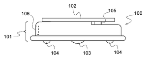
- FIG. 1 is a side view showing the appearance of the autonomous mobile device of this embodiment.
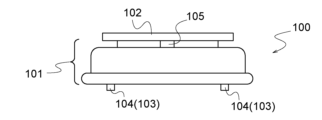
- FIG. 2 is a front view showing the appearance of the autonomous mobile device of this embodiment.
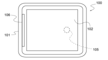
- FIG. 3 is a top view showing the appearance of the autonomous mobile device of this embodiment.
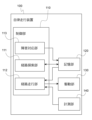
- FIG. 4 is a functional block diagram showing the functional configuration of the autonomous mobile device of this embodiment.
- FIG. 5 is a diagram showing an example of map information.
- FIG. 6 is a diagram showing details of map information.
- FIG. 7 is a graph showing an example of costs given to unitary domains other than obstacles.
- FIG. 8 is a diagram showing an example of a travel route.
- FIG. 9 is a diagram for explaining details of travel control in the autonomous mobile device.
- FIG. 10 is a diagram showing a state in which the autonomous mobile device travels through a narrow road.
- FIG. 11 is a diagram showing a state in which the autonomous mobile device runs in the vicinity of an obstacle with the obstacle viewed to the left.
- FIG. 12 is a diagram showing a state in which the autonomous mobile device runs in the vicinity of an obstacle with the obstacle viewed to the right.
- FIG. 13 is a diagram showing an example of a travel route searched while traveling on a narrow road.
- FIG. 14 is a flowchart showing control processing in traveling of the autonomous mobile device.
- FIG. 15 is a diagram showing contents of correction of map information by the fault handling unit.
- FIG. 16 is a diagram showing the result of route search in a bottleneck.
- FIG. 17 is a diagram showing the result of route search when the autonomous mobile device is located near the obstacle when viewed from the left.
- FIG. 18 is a diagram showing the result of route search when the autonomous mobile device is positioned near an obstacle as viewed to the right.
- FIG. 19 is a diagram showing an exceptional situation in virtual obstacle addition processing.
- FIG. 20 is a diagram showing exception processing in adding a virtual obstacle.
- FIG. 21 is a diagram showing another example of exception handling in adding a virtual obstacle.
- FIGS. 1 to 3 are diagrams showing the appearance of the autonomous mobile device of this embodiment. 1 shows a side view, FIG. 2 shows a front view, and FIG. 3 shows a top view.
- the autonomous mobile device 100 of this embodiment is a device called an AMR (Autonomous Mobile Robot) that transports materials and the like in factories and public places, for example.
- the autonomous mobile device 100 includes a main body 101, a loading platform 102, wheels 103, casters 104, a front sensor 105, and a rear sensor 106.
- the main unit 101 incorporates a computer for control, a power supply for driving, and the like.
- the main body 101 has a rectangular shape when viewed from above. "Rectangular shape" includes a rectangle, a rectangular shape with chamfered corners, and a rectangular shape with rounded corners.
- the position of the front sensor 105 may be illustrated as a mark for the front and rear of the autonomous mobile device 100 .
- Loads such as materials are loaded on the carrier 102 .
- the size of the load may exceed the size of the loading platform 102 or the main body 101, for convenience of explanation, unless otherwise specified, the case where the load fits within the size of the loading platform 102 will be exemplified below.
- the wheels 103 are provided on the left and right sides of the main body 101 and are driven to rotate by a motor inside the main body 101 .
- the left and right wheels 103 can be driven independently, and by driving the left and right wheels 103, the autonomous mobile device 100 can move forward, backward, turn on the spot, and turn (a so-called curve-drawing movement).
- the casters 104 are provided at each of the four corners of the main body 101 and support the main body 101 so that it does not tilt.
- the caster 104 does not have a driving force, rolls according to the movement of the main body 101 , and changes its direction according to the movement of the main body 101 .
- the front sensor 105 detects obstacles and the like in a wide range in front, left and right of the main body 101 .
- a 2D-LiDER for example, is used as the front sensor 105 .
- a rear sensor 106 detects an obstacle or the like behind the main body 101 .
- an infrared sensor or the like is used as the rear sensor 106 .
- the rear sensor 106 may have a plurality of sensor elements, and detection is performed by, for example, a plurality of sensor elements installed along the rear outer surface of the main body 101 .
- FIG. 4 is a functional block diagram showing the functional configuration of the autonomous mobile device 100 of this embodiment.
- the autonomous mobile device 100 includes a control section 110 , a storage section 120 , a drive section 130 and a measurement section 140 .
- the control unit 110 is a function performed by a computer built into the main unit 101, and controls the autonomous mobile device 100 as a whole.
- the storage unit 120 stores the map information of the area where the autonomous mobile device 100 travels and the route to travel on that area.
- the drive unit 130 is a function performed by the power source and motor built in the main body unit 101 and the wheel 103 .
- the autonomous mobile device 100 travels by driving the drive unit 130 according to the control by the control unit 110 .
- the measurement unit 140 is a function performed by the front sensor 105 and the rear sensor 106, and measures obstacles and the like.
- the control unit 110 includes a route searching unit 111, a route running unit 112, and a failure handling unit 113.
- the route search unit 111 searches for and determines a route to the destination based on the map information stored in the storage unit 120, and causes the storage unit 120 to store the determined route.
- the route search unit 111 searches for routes that can reach the destination while avoiding obstacles and the like shown in the map information, and determines the shortest route to reach the destination.
- the route running unit 112 controls the driving unit 130 so that the autonomous mobile device 100 runs along the route stored in the storage unit 120 .
- the route running unit 112 also performs control for avoiding obstacles measured by the measuring unit 140 .
- the obstacle handling unit 113 corrects the map information stored in the storage unit 120 to avoid being stuck when the obstacle measured by the measurement unit 140 is located at a predetermined short distance. Details of correction of map information by the failure handling unit 113 will be described later.
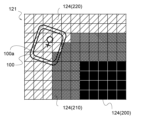
- FIG. 5 is a diagram showing an example of map information
- FIG. 6 is a diagram showing details of the map information.
- the map information 121 indicates information on the wall 122 and the shelf 123 .
- the walls 122 and the shelves 123 are obstacles to the traveling of the autonomous mobile device 100, and hereinafter, the walls 122 and the shelves 123 are collectively referred to as obstacles 200.
- the map information 121 represents a map as a set of unit blocks 124 in which the travel area of the autonomous mobile device 100 is partitioned in a grid pattern.
- a cost of "100" is given to the unitary domain 124 of the obstacle 200 as information indicating that it is the obstacle 200, and a cost of less than 100 is given to each unitary domain 124 other than that.
- a cost for each unitary domain 124 is given according to the distance from the obstacle 200, for example.
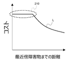
- FIG. 7 is a graph showing an example of costs given to unitary divisions 124 other than obstacles 200.
- FIG. The horizontal axis of the graph in FIG. 7 indicates the distance from the unitary domain 124 to the nearest obstacle 200, and the vertical axis indicates the given cost.
- each unitary domain 124 is represented, for example, by a graph line L that slopes downward to the right and protrudes downward. Also, the graph line L becomes a straight line parallel to the horizontal axis where the distance to the obstacle 200 is short. That is, the maximum cost is given to the unitary domain 124 whose distance is shorter than the predetermined distance.
- the unitary domains 124 assigned the highest cost are distributed around the obstacle 200 as shown in FIG.
- a unit area 124 that is far from the obstacle 200 and given a cost lower than the maximum cost is a drivable area 220 that can be part of the drivable route.
- the width of the travel prohibited area 210 (that is, the length of the straight line portion parallel to the horizontal axis on the graph line L) is arbitrarily determined based on the vehicle body size of the autonomous mobile device 100 and the like.
- the width of the travel-prohibited area 210 may be determined based on the lateral width of the autonomous mobile device 100, for example.
- the route search unit 111 described above searches for a travel route within the travelable area 220 and determines a travel route with a short travel length.
- FIG. 8 is a diagram showing an example of a travel route.
- the route search unit 111 uses the unitary section 124 where the vehicle body center 100a of the autonomous mobile device 100 is located on the map information 121 as the starting point 127, and the travel route 126 to the given destination 125 (for example, the destination of materials etc.). , the trajectory along which the vehicle body center 100a moves is searched within the travelable area 220. As shown in FIG. Further, the route search unit 111 searches and determines the travel route 126 so that the total cost given to each unitary section 124 on the travel route 126 is small. In other words, the route search unit 111 searches for a route with a smaller total cost as the travel route 126 .
- a travel route 126 with a short travel distance is searched and determined.
- the travel route 126 avoids the travel prohibited area 210, and the autonomous mobile device 100 travels while keeping the vehicle body center 100a from the obstacle 200 by a predetermined distance or more. do.
- the route search unit 111 in this embodiment searches for and determines a new travel route 126 even while the autonomous mobile device 100 is traveling along the travel route 126, and travels while continuing to update the travel route 126.
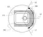
- FIG. 9 is a diagram explaining the details of travel control in the autonomous mobile device 100.
- the autonomous mobile device 100 has a stop area 310 around itself in order to avoid contact with the obstacle 200 during autonomous travel. stops running. When the autonomous mobile device 100 stops traveling, the autonomous mobile device 100 moves away from the obstacle 200 and performs recovery for restarting autonomous traveling. If the autonomous mobile device 100 cannot sufficiently move away from the obstacle 200 even after the recovery is executed, the autonomous mobile device 100 will be stuck and unable to travel autonomously.
- the autonomous mobile device 100 can move forward, backward, turn on the spot, and turn. In-place rotation by the autonomous mobile device 100 is performed when the direction of the determined travel route 126 is far from the direction of the autonomous mobile device 100 . More specifically, when the travel route 126 goes in a direction that crosses one of the limit lines L1 and L2 that are left and right with respect to the center line L0 of the autonomous mobile device 100, the autonomous mobile device 100 moves toward that direction. Perform a field turn to face the travel path 126 . Conversely, if the direction of the travel route 126 is within the prohibited range 330 sandwiched between the left and right limit lines L1 and L2, the autonomous mobile device 100 is prohibited from rotating in place. If the direction of the travel route 126 is within the prohibited range 330 and is different from the center line L0, the autonomous mobile device 100 turns toward the travel route 126. FIG.
- the autonomous mobile device 100 of the present embodiment is required to travel even in the vicinity of narrow roads and obstacles 200 to the extent that 360-degree on-the-spot rotation is impossible. In the vicinity of such a bottleneck or obstacle 200, if the autonomous mobile device 100 executes a spot turn, the stop area 310 will overlap the obstacle 200 and the autonomous mobile device 100 will stop.
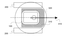
- FIG. 10 is a diagram showing a state in which the autonomous mobile device 100 travels through a bottleneck.
- FIG. 10 shows a bottleneck sandwiched by obstacles 200 .
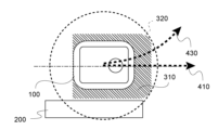
- the obstacle 200 across the bottleneck is located at a short distance on the free rotation circle 320 required for the autonomous mobile device 100 to turn 360 degrees in place.
- the stop area 310 is caught by the obstacle 200 and stops.
- the autonomous mobile device 100 can travel through a narrow road without getting stuck by traveling straight along the straight path 410 .
- FIG. 11 is a diagram showing a state in which the autonomous mobile device 100 runs near the obstacle 200 with the obstacle 200 viewed to the left.
- FIG. 11 shows the vicinity of an obstacle 200 , which is located to the left of the autonomous mobile device 100 at a short distance on the free rotation circle 320 .
- the autonomous mobile device 100 can travel in the vicinity of the obstacle 200 without getting stuck by traveling straight along the straight path 410 or by turning along the right front turning path 420 .
- FIG. 12 is a diagram showing a state in which the autonomous mobile device 100 runs near the obstacle 200 with the obstacle 200 viewed to the right.
- FIG. 12 shows the vicinity of an obstacle 200 , which is located to the right of the autonomous mobile device 100 at a short distance on the free rotation circle 320 .
- the autonomous mobile device 100 can travel in the vicinity of the obstacle 200 without getting stuck by traveling straight along the straight path 410 or by turning along the left front turning path 430 .
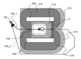
- FIG. 13 is a diagram showing an example of a travel route searched while traveling on a narrow road.
- FIG. 13 shows a bottleneck of width d sandwiched by obstacles 200 .
- the width d of the bottleneck is slightly larger than the width of the stop area 310 of the autonomous mobile device 100 .
- the travel prohibited area 210 is distributed around the obstacle 200 .
- a middle cost area 215 is distributed in which a cost lower than the maximum cost assigned to the travel prohibited area 210 but higher than the other portions of the travelable area 220 is assigned. .
- the width of the prohibited travel area 210 distributed around the obstacle 200 is, for example, less than half the width of the stop area 310, so the autonomous mobile device 100 in which the prohibited travel area 210 does not reach the center of the bottleneck. remains a medium cost area 215 in which the can run. Therefore, in the route search by the route search unit 111, the travel routes 126_1 and 126_2 passing through the bottleneck are also searched.
- the travel route 126_1 that goes through the bottleneck to the left and reaches the destination 125 is the one that goes through the bottleneck to the right. It is shorter than the travel route 126_2 that reaches the destination 125 with a lower total cost. For this reason, if the map information is not corrected by the failure handling unit 113, the traveling route 126_1 to the left is preferentially determined, and the autonomous mobile device 100 starts to turn on the spot to head left. As a result, the stop area 310 overlaps the obstacle 200 and the autonomous mobile device 100 stops.
- the failure handling unit 113 corrects the map information as described below in order to exclude from the route search the travel route 126_1 that reaches the destination 125 on the left side of the bottleneck shown in FIG.
- FIG. 14 is a flow chart showing the control processing in running of the autonomous mobile device 100.
- step S101 the autonomous mobile device 100 measures the obstacle 200 by controlling the measuring unit 140 using the route running unit 112.
- the route running unit 112 corresponds to an example of the confirming unit according to the present invention, and confirms whether or not there is an obstacle 200 at a short distance where spot rotation is impossible.
- the autonomous mobile device 100 corrects the map information 121 by the obstacle handling unit 113 in step S102.
- Step S102 corresponds to an example of the information adding process according to the present invention.
- FIG. 15 is a diagram showing the content of correction of the map information 121 by the failure handling unit 113.
- FIG. 15 is a diagram showing the content of correction of the map information 121 by the failure handling unit 113.
- the obstacle handling unit 113 corrects the map information 121 by adding an arcuate virtual obstacle 205 . That is, in this embodiment, the virtual obstacle 205 extends in an arc shape. A shape other than an arc may be used as the shape of the virtual obstacle referred to in the present invention. However, if the virtual obstacle 205 is arc-shaped, the virtual obstacle 205 reliably blocks the travel route directly behind the autonomous mobile device 100 regardless of the direction of the obstacle 200 around the autonomous mobile device 100. It is preferable because it can In addition, it is easy to calculate the position of the arc-shaped virtual obstacle 205 . The addition of the virtual obstacle 205 to the map information 121 is realized by giving the position of the virtual obstacle 205 the maximum cost explained in FIG.
- the virtual obstacle 205 extends along the free rotation circle 320 so as to surround the starting point 127, which is the vehicle center 100a.
- the virtual obstacle 205 continuously passes through the rear side of the autonomous mobile device 100 , passes through the left and right sides of the autonomous mobile device 100 , and reaches the front side of the autonomous mobile device 100 .
- the obstacle handling unit 113 corresponds to an example of the information addition unit according to the present invention, and the location information of the virtual obstacle 205 is added to the map information 121, and the position information of the virtual obstacle 205 is added to the starting point 127 of the travel route 126. position information of virtual obstacles 205 that continuously extend forward on both the left and right sides of the aircraft.
- the virtual obstacle 205 opens only within the prohibited range 330 on the front side of the autonomous mobile device 100 .
- the virtual obstacle 205 may open narrower than the prohibited range 330 . That is, both open ends 205a of the virtual obstacle 205 reach within the prohibited range 330 between the left and right limit lines L1 and L2. In other words, both ends 205a extending forward of the virtual obstacle 205 are positioned within a predetermined distance (within the prohibited range 330) from the forward direction (the direction of the center line L0) of the player's own aircraft.
- the open end 205a reaches the prohibited range 330, the travel route in the direction of the spot turn is reliably excluded from the search. Conversely, there is a degree of freedom in searching for a travel route within a range in which spot turns can be avoided.
- the autonomous mobile device 100 that has corrected the map information 121 by adding the virtual obstacle 205 in step S102 of FIG. .
- the route search unit 111 searches for the travel route 126 based on the map information 121 to which the position information of the virtual obstacle 205 is added.
- Step S103 corresponds to an example of the route search process referred to in the present invention.
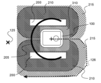
- FIG. 16 is a diagram showing the result of route search in a bottleneck.
- the virtual obstacles 205 added to the map information 121 overlap the obstacles 200 on the left and right sides of the autonomous mobile device 100, so a travel route toward the rear side of the autonomous mobile device 100 is searched. excluded from In addition, due to the travel-prohibited area 210 distributed around the obstacle 200, the travel route along which the autonomous mobile device 100 turns left and right is also excluded from the search.
- the travel route 126 that goes straight ahead of the autonomous mobile device 100 and passes through the bottleneck is searched and determined as the travel route 126. It will be.
- step S101 to step S104 in FIG. 14 is repeatedly executed until the autonomous mobile device 100 reaches the destination 125 (step S105: NO).
- a new travel route 126 is searched based on the map information 121 .
- the search for the travel route 126 is redone in accordance with changes in the circumstances around the autonomous mobile device 100, and a better travel route 126 is determined.
- step S105: YES the processing procedure of FIG. 14 ends.
- the virtual obstacle 205 added to the map information 121 in step S102 is temporarily deleted after the route search in step S103.
- a virtual obstacle 205 updated with reference to the position and orientation of the device 100 is repeatedly added to the map information 121 in step S102. That is, the position and orientation of the virtual obstacle 205 also change as the autonomous mobile device 100 moves.
- step S101: NO route search is performed without the virtual obstacle 205. and autonomous travel is performed (steps S103 and S104).
- the obstacle handling unit 113 adds the position information of the virtual obstacle 205 to the map information 121 when the obstacle 200 exists, and adds the position information of the virtual obstacle 205 to the map information when the obstacle 200 does not exist. Excluded from 121. As a result, when the autonomous mobile device 100 reaches a position where spot rotation is possible, the virtual obstacle 205 is removed and the degree of freedom of the travel route 126 increases.
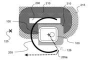
- FIG. 17 is a diagram showing the route search results when the autonomous mobile device 100 is positioned near the obstacle 200 when viewed on the left.
- step S101 of FIG. 14 it is determined in step S101 of FIG. 14 that the obstacle 200 exists in the vicinity of the autonomous mobile device 100, and the virtual obstacle 205 is added to the map information 121 in step S102.
- the virtual obstacle 205 added to the map information 121 overlaps with the obstacle 200 located to the left of the autonomous mobile device 100, so a travel route toward the rear side of the autonomous mobile device 100 is searched. excluded from In addition, due to the travel-prohibited area 210 distributed around the obstacle 200, the traveling route in which the autonomous mobile device 100 turns to the left is also excluded from the search.
- the traveling route 126 is the traveling route 126 that goes around the right opening end 205a of the virtual obstacle 205 from the front side of the autonomous mobile device 100. It will be searched and determined. Since the direction of the travel route 126 shown in FIG. 17 is within the range of the opening angle of the virtual obstacle 205, the autonomous mobile device 100 is prohibited from turning in place. In other words, since the autonomous mobile device 100 turns to the right front and leaves the obstacle 200, it can travel so that the stop area 310 does not overlap with the obstacle 200, thereby avoiding getting stuck.
- FIG. 18 is a diagram showing the result of route search when the autonomous mobile device 100 is positioned near the obstacle 200 when the obstacle 200 is viewed to the right.
- step S101 of FIG. 14 it is determined in step S101 of FIG. 14 that the obstacle 200 exists in the vicinity of the autonomous mobile device 100, and the virtual obstacle 205 is added to the map information 121 in step S102.
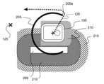
- the virtual obstacle 205 added to the map information 121 overlaps the obstacle 200 located on the right side of the autonomous mobile device 100, so a travel route toward the rear side of the autonomous mobile device 100 is searched. excluded from In addition, due to the travel-prohibited area 210 distributed around the obstacle 200, the travel route in which the autonomous mobile device 100 turns to the right is also excluded from the search.
- the traveling route 126 that goes around the left open end 205a of the virtual obstacle 205 from the front side of the autonomous mobile device 100 is selected as the travel route 126. It will be searched and determined. Since the direction of the travel route 126 shown in FIG. 18 is also within the range of the opening angle of the virtual obstacle 205, the autonomous mobile device 100 is prohibited from turning in place. That is, since the autonomous mobile device 100 turns to the front left and leaves the obstacle 200, it can travel so that the stop area 310 does not overlap the obstacle 200, thereby avoiding getting stuck.
- FIG. 19 is a diagram showing an exceptional situation in the virtual obstacle 205 addition process.
- FIG. 19 shows a destination 125a away from the autonomous mobile device 100 and a destination 125b near the autonomous mobile device 100.
- FIG. In the case of the destination 125a away from the autonomous mobile device 100, a travel route 126a leading to the front side of the autonomous mobile device 100 is searched and determined.
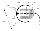
- a travel route 126b toward the rear side of the autonomous mobile device 100 from the starting point 127 to the destination 125b is There is a possibility that the autonomous mobile device 100 will rotate on the spot as it becomes a search target. Therefore, in step S102 shown in FIG. 14, when the destination 125b exists in the vicinity of the autonomous mobile device 100, exception processing described below is executed.
- FIG. 20 is a diagram showing exception processing in addition of the virtual obstacle 205.
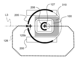
- the obstacle handling unit 113 adds a small arc-shaped virtual obstacle 206 inside the virtual obstacle 205 .
- the radius of the small virtual obstacle 206 is smaller than the distance from the starting point 127 to the destination 125b. That is, when the destination 125b exists inside the virtual obstacle 205 extending in an arc, the obstacle handling unit 113 creates an additional virtual obstacle 205 extending in an arc with a radius shorter than the distance from the starting point 127 to the destination 125b.
- the location information of the obstacle 206 is added to the map information 121.
- an opening is provided in the larger virtual obstacle 205 for the portion on the line L3 from the starting point 127 to the destination 125b. Due to such double arc-shaped virtual obstacles 205 and 206, the traveling route toward the rear of the autonomous mobile device 100 is excluded from the search, and as shown in FIG. A travel route 126 to is searched and determined.
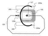
- FIG. 21 is a diagram showing another example of exception handling in addition of the virtual obstacle 205.
- the large virtual obstacle 205 may be deformed into an elliptical shape as shown in FIG. The position of the open end 205a is fixed during deformation, and the wall of the virtual obstacle 205 positioned behind the starting point 127 is deformed until it comes between the destination 125b and the starting point 127.
- AMR is mentioned as an application example of the autonomous mobile device and the control method of the autonomous mobile device of the present invention, but the application of the autonomous mobile device and the control method of the autonomous mobile device of the present invention is not limited to the above.
- AGVs Automatic Guided Vehicles
- self-driving cars are examples of the autonomous mobile device and the control method of the autonomous mobile device of the present invention.
- 100 autonomous mobile device, 100a: vehicle body center, 101: main body, 102: loading platform, 103: wheels, 104: casters, 105: front sensor, 106: rear sensor, 110: control unit, 111: route search unit, 112
Landscapes
- Engineering & Computer Science (AREA)
- Physics & Mathematics (AREA)
- General Physics & Mathematics (AREA)
- Automation & Control Theory (AREA)
- Remote Sensing (AREA)
- Radar, Positioning & Navigation (AREA)
- Aviation & Aerospace Engineering (AREA)
- Theoretical Computer Science (AREA)
- Mathematical Physics (AREA)
- Business, Economics & Management (AREA)
- Educational Administration (AREA)
- Educational Technology (AREA)
- Control Of Position, Course, Altitude, Or Attitude Of Moving Bodies (AREA)
Priority Applications (2)
| Application Number | Priority Date | Filing Date | Title |
|---|---|---|---|
| US18/696,362 US12585287B2 (en) | 2021-09-29 | 2022-06-17 | Autonomous traveling device and autonomous traveling device control method |
| JP2023550357A JPWO2023053602A1 (cg-RX-API-DMAC7.html) | 2021-09-29 | 2022-06-17 |
Applications Claiming Priority (2)
| Application Number | Priority Date | Filing Date | Title |
|---|---|---|---|
| JP2021159837 | 2021-09-29 | ||
| JP2021-159837 | 2021-09-29 |
Publications (1)
| Publication Number | Publication Date |
|---|---|
| WO2023053602A1 true WO2023053602A1 (ja) | 2023-04-06 |
Family
ID=85780570
Family Applications (1)
| Application Number | Title | Priority Date | Filing Date |
|---|---|---|---|
| PCT/JP2022/024259 Ceased WO2023053602A1 (ja) | 2021-09-29 | 2022-06-17 | 自律走行装置および自律走行装置の制御方法 |
Country Status (3)
| Country | Link |
|---|---|
| US (1) | US12585287B2 (cg-RX-API-DMAC7.html) |
| JP (1) | JPWO2023053602A1 (cg-RX-API-DMAC7.html) |
| WO (1) | WO2023053602A1 (cg-RX-API-DMAC7.html) |
Citations (4)
| Publication number | Priority date | Publication date | Assignee | Title |
|---|---|---|---|---|
| JP2009223812A (ja) * | 2008-03-18 | 2009-10-01 | Panasonic Electric Works Co Ltd | 自律移動装置 |
| JP2010061293A (ja) * | 2008-09-02 | 2010-03-18 | Toyota Motor Corp | 経路探索装置、経路探索方法、及び経路探索プログラム |
| JP2016201095A (ja) * | 2015-04-09 | 2016-12-01 | アイロボット コーポレイション | 移動ロボットの移動の制限 |
| JP2017211825A (ja) * | 2016-05-25 | 2017-11-30 | 村田機械株式会社 | 自己位置推定装置、及び、自己位置推定方法 |
Family Cites Families (14)
| Publication number | Priority date | Publication date | Assignee | Title |
|---|---|---|---|---|
| US5109566A (en) * | 1990-06-28 | 1992-05-05 | Matsushita Electric Industrial Co., Ltd. | Self-running cleaning apparatus |
| SE510524C2 (sv) * | 1997-09-19 | 1999-05-31 | Electrolux Ab | Elektroniskt avgränsningssystem |
| IL124413A (en) * | 1998-05-11 | 2001-05-20 | Friendly Robotics Ltd | System and method for area coverage with an autonomous robot |
| US6690134B1 (en) * | 2001-01-24 | 2004-02-10 | Irobot Corporation | Method and system for robot localization and confinement |
| US7663333B2 (en) * | 2001-06-12 | 2010-02-16 | Irobot Corporation | Method and system for multi-mode coverage for an autonomous robot |
| EP1395888B1 (en) * | 2001-06-12 | 2011-05-18 | iRobot Corporation | Method and system for multi-mode coverage for an autonomous robot |
| US20040236468A1 (en) * | 2003-03-14 | 2004-11-25 | Taylor Charles E. | Robot vacuum with remote control mode |
| US8706297B2 (en) * | 2009-06-18 | 2014-04-22 | Michael Todd Letsky | Method for establishing a desired area of confinement for an autonomous robot and autonomous robot implementing a control system for executing the same |
| US8364309B1 (en) * | 2009-07-14 | 2013-01-29 | Bailey Bendrix L | User-assisted robot navigation system |
| CN102713779B (zh) * | 2009-11-06 | 2015-12-02 | 艾罗伯特公司 | 用于通过自主型机器人完全覆盖表面的方法和系统 |
| JP6301713B2 (ja) | 2013-08-12 | 2018-03-28 | 株式会社Soken | 走行経路生成装置 |
| WO2018116769A1 (ja) | 2016-12-19 | 2018-06-28 | 株式会社クボタ | 走行経路管理システム |
| US11709489B2 (en) * | 2017-03-02 | 2023-07-25 | RobArt GmbH | Method for controlling an autonomous, mobile robot |
| CN114008552B (zh) | 2019-06-18 | 2024-10-18 | 株式会社Ihi | 行驶路径生成装置以及控制装置 |
-
2022
- 2022-06-17 JP JP2023550357A patent/JPWO2023053602A1/ja active Pending
- 2022-06-17 US US18/696,362 patent/US12585287B2/en active Active
- 2022-06-17 WO PCT/JP2022/024259 patent/WO2023053602A1/ja not_active Ceased
Patent Citations (4)
| Publication number | Priority date | Publication date | Assignee | Title |
|---|---|---|---|---|
| JP2009223812A (ja) * | 2008-03-18 | 2009-10-01 | Panasonic Electric Works Co Ltd | 自律移動装置 |
| JP2010061293A (ja) * | 2008-09-02 | 2010-03-18 | Toyota Motor Corp | 経路探索装置、経路探索方法、及び経路探索プログラム |
| JP2016201095A (ja) * | 2015-04-09 | 2016-12-01 | アイロボット コーポレイション | 移動ロボットの移動の制限 |
| JP2017211825A (ja) * | 2016-05-25 | 2017-11-30 | 村田機械株式会社 | 自己位置推定装置、及び、自己位置推定方法 |
Also Published As
| Publication number | Publication date |
|---|---|
| US20240385624A1 (en) | 2024-11-21 |
| US12585287B2 (en) | 2026-03-24 |
| JPWO2023053602A1 (cg-RX-API-DMAC7.html) | 2023-04-06 |
Similar Documents
| Publication | Publication Date | Title |
|---|---|---|
| JP7188338B2 (ja) | 自動駐車システム | |
| EP3900509B1 (en) | Field operation vehicle | |
| JP7047659B2 (ja) | 無人搬送車の制御装置及び制御方法 | |
| JP2020006718A (ja) | 走行車両の自動テスト走行システム | |
| JP2009101776A (ja) | 車両用駐車支援装置 | |
| WO2013165303A1 (en) | Method and system for manoeuvring a mobile mining machine in a tunnel and a mobile mining machine | |
| WO2022149389A1 (ja) | 自動走行システム及び自動走行方法 | |
| CN116161143A (zh) | 无人搬运装置 | |
| JP3841206B2 (ja) | 無人搬送車 | |
| JP2009129016A (ja) | 移動経路作成方法、自律移動体及び自律移動体制御システム | |
| US12585287B2 (en) | Autonomous traveling device and autonomous traveling device control method | |
| US20240361134A1 (en) | Autonomous travel device and autonomous travel device control method | |
| JP7816261B2 (ja) | 車両 | |
| JP2009223561A (ja) | 無人搬送台車の進路変更方法および進路変更装置 | |
| JP2021015414A (ja) | 無人搬送車 | |
| JP5134403B2 (ja) | 無人搬送車およびその制御方法並びに無人搬送車の走行ライン | |
| JP7618165B2 (ja) | 自動運転車両 | |
| JP2008024195A (ja) | 車両用誘導経路探索装置 | |
| WO2023042502A1 (ja) | 自律走行装置および自律走行装置の制御方法 | |
| JPH09114522A (ja) | 自律制御の教示による無人搬送車の運転方法 | |
| JP2001318718A (ja) | 無軌道自動搬送車及び自動搬送車の制御方法 | |
| JP7845252B2 (ja) | 無人走行体の走行制御システム | |
| JP2021082122A (ja) | 無人搬送車 | |
| JP2000099149A (ja) | Agv用警報装置 | |
| JP3804235B2 (ja) | 無人搬送車 |
Legal Events
| Date | Code | Title | Description |
|---|---|---|---|
| 121 | Ep: the epo has been informed by wipo that ep was designated in this application |
Ref document number: 22875481 Country of ref document: EP Kind code of ref document: A1 |
|
| WWE | Wipo information: entry into national phase |
Ref document number: 2023550357 Country of ref document: JP |
|
| WWE | Wipo information: entry into national phase |
Ref document number: 18696362 Country of ref document: US |
|
| NENP | Non-entry into the national phase |
Ref country code: DE |
|
| 122 | Ep: pct application non-entry in european phase |
Ref document number: 22875481 Country of ref document: EP Kind code of ref document: A1 |
|
| WWG | Wipo information: grant in national office |
Ref document number: 18696362 Country of ref document: US |