WO2023053471A1 - 主軸装置 - Google Patents
主軸装置 Download PDFInfo
- Publication number
- WO2023053471A1 WO2023053471A1 PCT/JP2022/001553 JP2022001553W WO2023053471A1 WO 2023053471 A1 WO2023053471 A1 WO 2023053471A1 JP 2022001553 W JP2022001553 W JP 2022001553W WO 2023053471 A1 WO2023053471 A1 WO 2023053471A1
- Authority
- WO
- WIPO (PCT)
- Prior art keywords
- spindle
- collet
- air supply
- main shaft
- air
- Prior art date
- Legal status (The legal status is an assumption and is not a legal conclusion. Google has not performed a legal analysis and makes no representation as to the accuracy of the status listed.)
- Ceased
Links
Images







Classifications
-
- B—PERFORMING OPERATIONS; TRANSPORTING
- B23—MACHINE TOOLS; METAL-WORKING NOT OTHERWISE PROVIDED FOR
- B23Q—DETAILS, COMPONENTS, OR ACCESSORIES FOR MACHINE TOOLS, e.g. ARRANGEMENTS FOR COPYING OR CONTROLLING; MACHINE TOOLS IN GENERAL CHARACTERISED BY THE CONSTRUCTION OF PARTICULAR DETAILS OR COMPONENTS; COMBINATIONS OR ASSOCIATIONS OF METAL-WORKING MACHINES, NOT DIRECTED TO A PARTICULAR RESULT
- B23Q1/00—Members which are comprised in the general build-up of a form of machine, particularly relatively large fixed members
- B23Q1/70—Stationary or movable members for carrying working-spindles for attachment of tools or work
-
- B—PERFORMING OPERATIONS; TRANSPORTING
- B23—MACHINE TOOLS; METAL-WORKING NOT OTHERWISE PROVIDED FOR
- B23B—TURNING; BORING
- B23B31/00—Chucks; Expansion mandrels; Adaptations thereof for remote control
- B23B31/02—Chucks
- B23B31/24—Chucks characterised by features relating primarily to remote control of the gripping means
- B23B31/26—Chucks characterised by features relating primarily to remote control of the gripping means using mechanical transmission through the working-spindle
- B23B31/261—Chucks characterised by features relating primarily to remote control of the gripping means using mechanical transmission through the working-spindle clamping the end of the toolholder shank
- B23B31/265—Chucks characterised by features relating primarily to remote control of the gripping means using mechanical transmission through the working-spindle clamping the end of the toolholder shank by means of collets
-
- B—PERFORMING OPERATIONS; TRANSPORTING
- B23—MACHINE TOOLS; METAL-WORKING NOT OTHERWISE PROVIDED FOR
- B23B—TURNING; BORING
- B23B31/00—Chucks; Expansion mandrels; Adaptations thereof for remote control
- B23B31/02—Chucks
- B23B31/24—Chucks characterised by features relating primarily to remote control of the gripping means
- B23B31/26—Chucks characterised by features relating primarily to remote control of the gripping means using mechanical transmission through the working-spindle
- B23B31/261—Chucks characterised by features relating primarily to remote control of the gripping means using mechanical transmission through the working-spindle clamping the end of the toolholder shank
-
- B—PERFORMING OPERATIONS; TRANSPORTING
- B23—MACHINE TOOLS; METAL-WORKING NOT OTHERWISE PROVIDED FOR
- B23Q—DETAILS, COMPONENTS, OR ACCESSORIES FOR MACHINE TOOLS, e.g. ARRANGEMENTS FOR COPYING OR CONTROLLING; MACHINE TOOLS IN GENERAL CHARACTERISED BY THE CONSTRUCTION OF PARTICULAR DETAILS OR COMPONENTS; COMBINATIONS OR ASSOCIATIONS OF METAL-WORKING MACHINES, NOT DIRECTED TO A PARTICULAR RESULT
- B23Q11/00—Accessories fitted to machine tools for keeping tools or parts of the machine in good working condition or for cooling work; Safety devices specially combined with or arranged in, or specially adapted for use in connection with, machine tools
-
- B—PERFORMING OPERATIONS; TRANSPORTING
- B23—MACHINE TOOLS; METAL-WORKING NOT OTHERWISE PROVIDED FOR
- B23Q—DETAILS, COMPONENTS, OR ACCESSORIES FOR MACHINE TOOLS, e.g. ARRANGEMENTS FOR COPYING OR CONTROLLING; MACHINE TOOLS IN GENERAL CHARACTERISED BY THE CONSTRUCTION OF PARTICULAR DETAILS OR COMPONENTS; COMBINATIONS OR ASSOCIATIONS OF METAL-WORKING MACHINES, NOT DIRECTED TO A PARTICULAR RESULT
- B23Q3/00—Devices holding, supporting, or positioning work or tools, of a kind normally removable from the machine
- B23Q3/12—Devices holding, supporting, or positioning work or tools, of a kind normally removable from the machine for securing to a spindle in general
-
- B—PERFORMING OPERATIONS; TRANSPORTING
- B23—MACHINE TOOLS; METAL-WORKING NOT OTHERWISE PROVIDED FOR
- B23B—TURNING; BORING
- B23B2270/00—Details of turning, boring or drilling machines, processes or tools not otherwise provided for
- B23B2270/30—Chip guiding or removal
Definitions
- This disclosure relates to a spindle device.
- the spindle of the spindle device used for machine tools is provided with a tapered hole that allows the tool to be detachably received.
- a technique for ejecting foreign matter by providing an air ejection hole in the inner peripheral surface of the tapered hole and ejecting air from the air ejection hole.
- the air may swirl in the circumferential direction of the tapered hole.
- the vicinity of the axis of the tapered hole becomes negative pressure, and a suction phenomenon may occur in which foreign matter is taken into the tapered hole. Therefore, in the spindle device of Patent Document 1, in addition to the air discharge holes (swirling flow discharge holes) provided in the tapered holes, there are provided direct current discharge holes for discharging air traveling straight in the axial direction of the tapered holes.
- a spindle device includes a spindle housing, a spindle rotatably supported by the spindle housing, a tapered hole located at one end to which a tool is detachably mounted, and a tapered hole on the other end side of the tapered hole.
- a main shaft cylindrical portion communicating with the tapered hole; a collet chuck disposed in the main shaft cylindrical portion, the collet chuck holding the tool; and a collet other end portion of the collet chuck.
- a draw bar connected to and moving the collet chuck back and forth along the axial direction of the main shaft.
- the collet chuck has a plurality of claws for gripping the tool, and includes a plurality of claws arranged in a circumferential direction about the central axis of the main shaft, and an annular collet forming one end of the collet, which extends from one end of the main shaft.
- a plurality of collet gaps extending to the other end side of the and forming a flow path for guiding air to the tapered hole, the plurality of collet gaps being gaps between the claw portions of the plurality of claw portions; a collet cam surface, wherein the main shaft cylindrical portion has a storage space in which the other end of the collet is stored in a clamped state; It has a cam surface that comes into contact with the collet cam surface when the collet cam surface is used.
- the main shaft has an air supply path for supplying air to the storage space in an unclamped state.
- the air supplied to the air supply path temporarily stays in the storage space, passes from the storage space through the gap between the main shaft cylindrical portion and the outer periphery of the collet, flows through the collet gap, and is discharged from the tapered hole. be done. Since the air circulates through the collet gap and becomes a straight flow, it is possible to suppress the occurrence of the suction phenomenon near the axis of the tapered hole.
- a plurality of air supply paths may be provided. According to this aspect, since the air can be supplied to the storage space from the plurality of air supply paths, the air can be uniformly supplied to the plurality of collet gaps.
- relative positions of the plurality of collet clearances with respect to the air supply passages of the plurality of air supply passages may be the same.
- all the air supply paths have the same path from the air supply path to the collet clearance. Therefore, the flow of air ejected from the air supply path is less likely to be biased, and the air can easily flow straight through the tapered hole, thereby suppressing the occurrence of the suction phenomenon.
- the number of the plurality of collet gaps and the number of the plurality of air supply paths are the same, the plurality of collet gaps are arranged at regular intervals, and the plurality of air supply paths are arranged at equal intervals.
- the supply channels may be arranged at regular intervals. According to this aspect, the air ejected from all the air supply paths is guided to the nearby air gaps. Therefore, the air flow is less likely to be biased, the air flows straight, and the occurrence of the suction phenomenon can be suppressed.
- the plurality of air supply paths extend along the radial direction of the spindle, and the phase positions of the plurality of air supply paths and the phase positions of the plurality of collet gaps are the same. You may According to this configuration, the air ejected from each air supply passage smoothly flows to the nearest collet gap, so that the air flow is less likely to be disturbed.
- the spindle device of the above aspect further includes a biasing member that biases the drawbar in the axial direction away from the tapered hole, and a biasing member that biases the drawbar toward the tapered hole in the unclamped state. and a cylinder device for pushing toward.
- the present application can be applied to a spindle device including an urging member and a cylinder device.
- an inner pipe arranged in the draw bar, one end of the pipe forming one end, and one end of the pipe closer to the other end of the main shaft than the one end of the pipe a pipe air supply path arranged outside the inner pipe and extending from the one end of the pipe to the other end of the pipe; and arranged close to the other end of the pipe.
- a second end air passage for introducing air into the pipe air supply passage, the other end air passage through which air flows radially inward of the inner pipe;
- a one-end air channel for discharging air from the pipe air supply channel, the one-end air channel through which air flows outward in the radial direction of the inner pipe, and between the main shaft and the draw bar.
- a collet sleeve disposed between the main shaft and the drawbar and adjacent to the guide sleeve in the axial direction; and a gap between the guide sleeve and the drawbar.
- a third air supply passage communicating with the one end air passage; and a guide sleeve passage formed at one end of the guide sleeve and extending along the radial direction of the guide sleeve, the third air supply passage and a collet sleeve channel formed between the main shaft and the collet sleeve, the other end communicating with the guide sleeve channel, and the one end communicating with the plurality of air supply channels. and a coolant channel arranged inside the inner pipe.
- the present application can be applied to a spindle device including an inner pipe, a pipe air supply path, a guide sleeve flow path, a collet sleeve flow path, and a coolant flow path.
- a spindle device including an inner pipe, a pipe air supply path, a guide sleeve flow path, a collet sleeve flow path, and a coolant flow path.
- an air communication passage formed outside the main shaft air supply passage in the radial direction for supplying air from the outside to the air supply passage; a front-side bearing arranged at a position near the one end of the main shaft in the direction, the front-side bearing rotatably supporting the main shaft, wherein the air communication path is arranged in the axial direction by There may be a one-end-side flow path positioned closer to the one-end side than the front-side bearing and formed between the main shaft housing and the main shaft.
- the spindle further includes a spindle cap forming the tapered hole
- the spindle housing further includes a front cap forming one end of the housing of the spindle housing.
- a channel may be formed in the spindle cap and the front cap.
- the spindle cap and the front cap can be easily assembled to the spindle device, so that the one end flow path can be easily formed in the spindle device.
- the spindle housing has a first end surface in which a first opening that forms the one end flow path is formed, and the spindle has a second opening that forms the one end flow path.
- a second end face having an opening formed thereon, the second end face facing the first end face in the axial direction, and the one-end-side channel includes the first opening and the second opening. , and an axial flow path extending in the axial direction.
- the flow path extending over the main shaft housing, which is a non-rotating element, and the main shaft, which is a rotating element can be formed as an axial flow path.
- the spindle cap includes a cap small diameter portion positioned radially inside the front cap and a cap large diameter portion positioned closer to the other end than the front cap in the axial direction. and a cap large-diameter portion having an outer diameter larger than that of the cap small-diameter portion, and the second end face may be formed in the cap large-diameter portion.
- the second end surface can be easily formed using the cap large-diameter portion of the spindle cap.
- a biasing member that biases the drawbar in the axial direction away from the tapered hole pushes the drawbar toward the tapered hole in the unclamped state.
- a cylinder device wherein the first end surface and the second end surface are separated in the clamped state, and the second end surface is brought into contact with the first end surface in the unclamped state.
- the first end surface and the second end surface are in contact with each other, so that the axial flow path can be communicated with each other.
- the spindle housing includes a sleeve that surrounds the spindle in the axial direction, and the sleeve has an outer peripheral surface, the first end surface, and a third end surface that protrudes from the outer peripheral surface.
- the spindle housing further has a fourth end face facing the third end face in the axial direction, and the spindle device is further arranged between the third end face and the fourth end face.
- the sealing material may be compressed in the axial direction in the unclamped state to urge the sleeve toward the second end surface.
- the above aspect may further include a holding plate attached to the front cap and having the fourth end surface.
- the pressing plate can form the fourth end surface.
- the main shaft housing has an inner peripheral surface of the one end side housing in which an inner peripheral surface opening forming the one end flow path is formed, and the main shaft defines the one end flow path.
- the main shaft has an outer peripheral surface on the one end side in which an outer peripheral surface opening is formed, and in the unclamped state, the outer peripheral surface opening is disposed at a position facing the inner peripheral surface opening in the radial direction, and the
- the one-end channel may have a radial channel that includes the inner peripheral surface opening and the outer peripheral surface opening, and extends in the radial direction in the unclamped state.
- the channel extending over the spindle housing, which is a non-rotating element, and the spindle, which is a rotating element can be formed as a radial channel.
- the present disclosure can be embodied in various forms, and can be embodied in the form of, for example, a method of manufacturing a spindle device, in addition to the spindle device described above.
- FIG. 2 is an enlarged view of region R2 in FIG. 1; A perspective view of a collet chuck.
- FIG. 2 is an enlarged cross-sectional view of the collet chuck; The figure which looked at the collet chuck along the central axis.
- the 1st schematic diagram which shows sectional drawing of the spindle device of 2nd Embodiment.
- the 2nd schematic diagram which shows sectional drawing of the spindle device of 2nd Embodiment.
- the schematic diagram which shows some spindle devices.
- FIG. 12 is a schematic diagram of part of the spindle device shown in FIG. 11; Fig. 1 for explaining another embodiment of the second embodiment; FIG. 2 for explaining another embodiment of the second embodiment;
- FIG. 1 is a schematic diagram showing a longitudinal section of the spindle device 1 of the first embodiment.
- FIG. 2 is an enlarged view of region R2 in FIG.
- the spindle device 1 of this embodiment is a motor built-in type spindle device provided in a machine tool such as a machining center.
- the spindle device 1 grips a tool for machining a workpiece on the front side.
- the tool is specifically configured by attaching a machining tool to a tool holder.
- FIG. 1 shows the central axis AX of the spindle 10 of the spindle device 1 .
- the upper half of the figure above the center axis AX shows the unclamped state in which the grip of the tool holder is released, and the lower half of the figure below the center axis AX shows the clamped state in which the tool holder is gripped. It is illustrated in the same way in FIG. 4 which will be described later.
- the side where the tool is gripped is defined as the front side
- the side opposite to the side where the tool is gripped is defined as the rear side.
- the upper side of the paper surface of FIG. 1 is the vertically upward direction side
- the lower side of the paper surface is the vertically downward direction side.
- the spindle device 1 includes a cylindrical spindle housing 3, a spindle 10, a front side bearing 10A, a rear side bearing 10B, an electric motor 40, a draw bar 30, a collet chuck 20, and a disk spring as a biasing member. 33 , a cylinder device 15 and a control device 90 .
- the spindle housing 3 arranges main elements of the spindle device 1 such as the spindle 10 and the electric motor 40 inside.
- the main shaft 10 is rotatably supported by the main shaft housing 3 via two front side bearings 10A and rear side bearings 10B.
- the main shaft 10 has a central axis AX and is rotated around the central axis AX by being driven by the electric motor 40 .
- the main shaft 10 has one end portion 10F, which is the end portion on the front side, and the other end portion 10R facing the one end portion 10F.
- the main shaft 10 has a tapered hole 10T that penetrates in the axial direction, a main shaft cylindrical portion 10H, and a spindle cap 10C.
- the tapered hole 10T is located at one end, that is, one end 10F of the spindle 10, and a tool is detachably attached thereto.
- the main shaft cylindrical portion 10H is located on the other end side of the tapered hole 10T, that is, on the other end portion 10R side of the main shaft 10 .
- the main shaft cylindrical portion 10H communicates with the tapered hole 10T.
- the front side bearing 10A is an angular rolling bearing arranged at a position on the front side of the electric motor 40 in the axial direction.
- Two front side bearings 10A are arranged with an interval in the axial direction.
- the front side bearing 10A is interposed between the main shaft housing 3 and the main shaft 10 in the radial direction of the main shaft 10 perpendicular to the axial direction.
- the rear side bearing 10B is a roller-type rolling bearing arranged at a position on the rear side of the electric motor 40 in the axial direction.
- the rear side bearing 10B is interposed between the main shaft housing 3 and the main shaft 10 in the radial direction of the main shaft 10 .
- the electric motor 40 has a rotor 41 and a stator 42 .
- the electric motor 40 is arranged on the outer circumference of the main shaft 10 inside the main shaft housing 3 .
- the rotor 41 is configured to be rotatable together with the main shaft 10 .
- Power is supplied to the stator 42 under the control of the control device 90 to rotate the rotor 41 , thereby rotating the main shaft 10 .
- the collet chuck 20 is arranged inside the main shaft cylindrical portion 10H.
- the collet chuck 20 advances and retreats along the axial direction of the spindle 10 in conjunction with the draw bar 30, thereby either clamping the tool or unclamping the tool. take.
- the collet chuck 20 is in an unclamped state when the drawbar 30 is pushed forward by the cylinder device 15 and moves toward the one end 30F of the drawbar.
- the collet chuck 20 is in a clamped state when the drawbar 30 is separated from the cylinder device 15 and moved toward the drawbar other end portion 30R by the biasing force of the disc spring 33 .
- the draw bar 30 is arranged on the main shaft cylindrical portion 10H.
- the draw bar 30 is connected to the collet chuck 20 and moves the collet chuck 20 back and forth along the central axis AX direction of the spindle 10 .
- the drawbar 30 has a drawbar one end portion 30F located on the one end portion 10F side and a drawbar other end portion 30R located on the other end portion 10R side.
- the drawbar 30 is movable along the axial direction of the main shaft 10 by the operation of the cylinder device 15, which will be described later.
- the drawbar 30 is connected to the main shaft 10 so as to interlock with the rotational movement of the main shaft 10 .
- the disc spring 33 is arranged between the inner peripheral surface of the main shaft 10 and the draw bar 30 in the main shaft cylindrical portion 10H inside the main shaft 10 .
- the disc spring 33 is arranged in the axial direction of the main shaft 10 between a collar 34 arranged on the inner circumference of the main shaft 10 and a large diameter portion 30D formed at the drawbar other end portion 30R of the drawbar 30. More specifically, the disc spring 33 is arranged so as to pass through the outer periphery of the draw bar 30 .
- a plurality of disk springs 33 are provided along the axial direction. The rear end of the disc spring 33 abuts on the large diameter portion 30D of the drawbar 30 on the side of the other drawbar end 30R in the axial direction.
- the disc spring 33 applies a biasing force to the draw bar 30 in a direction away from the tapered hole 10T, that is, in a direction from the one end 10F to the other end 10R. Due to this biasing force, the collet chuck 20 is always clamped when the cylinder device 15 is not in operation. It should be noted that the disc spring 33 may be coated with grease in order to reduce the frictional force.
- the cylinder device 15 is arranged on the rear side of the drawbar 30 in the axial direction.
- the cylinder device 15 has a piston 18 configured to be axially movable.
- the piston 18 axially opposes the other drawbar end 30R of the drawbar 30 .
- the draw bar 30 is moved forward by the piston 18 against the biasing force of the disc spring 33 .
- the collet chuck 20 is in an unclamped state.
- the control device 90 is composed of a CPU, a storage device, etc., and controls the operation of the spindle device 1 .
- the control device 90 controls the operation of the electric motor 40 of the spindle device 1 .
- the spindle device 1 further includes an air supply device 92 and a coolant supply device 95 .
- the operations of the air supply device 92 and the coolant supply device 95 are controlled by the control device 90 .
- the air supply device 92 is, for example, a compressor, and feeds pressurized air into a flow path provided in the piston 18 of the cylinder device 15 . Chips adhering to the tapered hole 10T are removed.
- the coolant supply device 95 supplies coolant to the axially extending coolant passage 130 through the opening 85 on the rear end side of the cylinder device 15 .
- the coolant flows through the coolant channel 130, passes through the drawbar one end 30F and the inside of the tool, and is supplied to the machining point, which is the cutting edge of the tool.
- the drawbar 30 is composed of an outer drawbar 30A, a push rod 37, and a draw bolt 26.
- an inner pipe 36 is arranged inside the outer draw bar 30A. Specifically, both ends of the inner pipe 36 protrude in the outer diameter direction. Both protruding ends of the inner pipe 36 are press-fitted to the inner periphery of the outer draw bar 30A.
- a large-diameter portion 30 ⁇ /b>D formed on the drawbar other end portion 30 ⁇ /b>R side of the outer peripheral drawbar 30 ⁇ /b>A abuts on the disc spring 33 .
- the outer drawbar 30A is a cylindrical member and has a first rod hole 31H extending therethrough in the axial direction.
- the inner pipe 36 is a cylindrical member, is arranged in the first rod hole 31H, and has a second rod hole 32H penetrating in the axial direction.
- the inner pipe 36 has a pipe one end 36A (FIG. 1) forming one end and a pipe other end 36B closer to the other end 10R than the pipe one end 36A.
- the inner periphery of the push rod 37 is connected to the outer periphery of the outer draw bar 30A by screw fitting.
- Draw bolt 26 is generally cylindrical in shape. As shown in FIG. 4, which will be described later, the draw bolt other end 28, which is the rear end of the draw bolt 26, is connected to the push rod 37 by screwing. As shown in FIG.
- the spindle device 1 further has a guide sleeve 30G and a collet sleeve 30H.
- a guide sleeve 30G is arranged between the main shaft 10 and the drawbar 30 .
- the collet sleeve 30H is arranged between the spindle 10 (specifically, the spindle main body) and the push rod 37 .
- the collet sleeve 30H is arranged axially adjacent to the guide sleeve 30G.
- a guide sleeve 30G, a collet sleeve 30H, and a spindle cap 10C are fitted in order on the inner periphery of the main shaft 10, and the spindle cap 10C is fixed to the main shaft 10 (specifically, the main shaft main body) with bolts.
- the guide sleeve 30G and the collet sleeve 30H are axially sandwiched between the stepped portion 10D of the spindle 10 and the spindle cap 10C and fixed to the spindle 10 (specifically, the spindle body).
- the spindle cap 10C, the guide sleeve 30G, and the collet sleeve 30H rotate together with the main spindle body to form the main spindle 10. As shown in FIG.
- the spindle device 1 includes a coolant passage 130 (FIGS. 1 and 2) that supplies coolant to a machining point to be machined by the tool gripped by the collet chuck 20, and air that blows onto the tapered hole 10T. and a supply channel 120 (FIGS. 1 and 2).
- the coolant passage 130 includes a first coolant passage 19 ( FIG. 1 ) formed in the cylinder device 15 , a fourth coolant passage 47 a ( FIG. 1 ) formed in the fixed joint 47 , and a fourth coolant passage 47 a ( FIG. 1 ) formed in the rotary joint 46 . It has a second coolant channel 48 ( FIG. 2 ), a third coolant channel 38 ( FIGS. 1 and 2 ) formed in the inner pipe 36 , a fifth coolant channel 49 , and a sixth coolant channel 50 . As shown in FIG. 2 , the third coolant channel 38 as a coolant channel is arranged inside the inner pipe 36 and formed by the second rod hole 32H of the inner pipe 36 . As shown in FIG.
- the fifth coolant passage 49 is arranged inside the push rod 37 .
- the sixth coolant channel 50 is arranged inside the tubular spool 25 ( FIG. 4 ) arranged inside the draw bolt 26 .
- the coolant supplied from the coolant supply device 95 flows through the first coolant flow path 19, the fourth coolant flow path 47a, the second coolant flow path 48, the third coolant flow path 38, the fifth coolant flow path 49, the sixth coolant flow It circulates in the order of the path 50, passes through the inside of the tool, is positioned on the side of the one end portion 10F, and is supplied to the machining point, which is the cutting edge of the tool.
- the coolant channel 130 is a channel formed along the axial direction.
- the coolant supply device 95 supplies coolant to the coolant flow path 130 in response to a command from the control device 90 while the main shaft 10 is rotating in the clamped state.
- the air supply path 120 is located downstream of the upstream air supply path 55 (FIGS. 1 and 2) formed in the non-rotating element of the spindle device 1 and the upstream air supply path 55, a downstream air supply passage 56 (FIG. 1) formed in the element.
- the upstream air supply passage 55 is formed in the piston 18, which is a non-rotating element.
- the upstream air supply passage 55 is also called the first air supply passage 55 .
- the downstream air supply path 56 is formed by a second air supply path 35 (FIGS. 1 and 2) formed inside the drawbar 30 and between the drawbar 30 and the inner pipe 36, and a gap between the main shaft 10 and the drawbar 30.
- the downstream end of the first air supply path 55 is an opening formed in the piston 18 at a position facing the drawbar 30 in the axial direction.
- the first air supply passage 55 of the piston 18 is connected to the second air supply passage 35 of the drawbar 30 when the end surfaces of the piston 18 and the drawbar 30 are in contact with each other.
- the second air supply path 35 has an upstream side flow path 35A formed in the outer peripheral draw bar 30A, the other end air flow path 35C, the downstream side flow path 35B, and the one end air flow path 35D (Fig. 1). .
- a downstream channel 35B as a pipe air supply channel is formed by a gap between the inner peripheral surface of the outer peripheral drawbar 30A and the outer peripheral surface of the inner pipe 36.
- the downstream flow path 35B is arranged outside the inner pipe 36 and extends from the pipe one end 36A to the pipe other end 36B.
- the downstream passage 35B communicates with a plurality of main shaft air supply passages 156, which will be described later.
- the other end air channel 35C is located between the upstream channel 35A and the downstream channel 35B.
- 35 C of other end air flow paths are arrange
- the other end air channel 35 ⁇ /b>C extends in the radial direction of the inner pipe 36 .
- the air flows radially inwardly of the inner pipe 36 through the other end air flow path 35C and flows into the downstream flow path 35B.
- the one end air channel 35D (FIG.
- the one-end air channel 35D is arranged close to the pipe one-end portion 36A.
- the one end air channel 35D extends in the radial direction of the push rod 37 and the outer drawbar 30A. The air flows radially outward of the push rod 37 and the outer drawbar 30A through the first air passage 35D and flows out to the third air supply passage 125. As shown in FIG.
- the third air supply path 125 is formed by a gap between the guide sleeve 30G and the push rod 37.
- the third air supply path 125 communicates with the second air supply path 35 .
- the guide sleeve 30G has a large diameter portion 30I protruding in the outer diameter direction at one end.
- the large diameter portion 30I is in contact with the stepped portion 10D of the main shaft 10 .
- a fourth air supply passage 155 is formed between the inner circumference of the spindle 10 and the outer circumference of the large diameter portion 30I.
- the sixth air supply path 126 is formed on the stepped portion 10D side of the main shaft 10 of the large diameter portion 30I.
- the sixth air supply path 126 is formed on the stepped portion 10D side of the large diameter portion 30I of the guide sleeve 30G and extends in the radial direction of the large diameter portion 30I.
- the sixth air supply path 126 connects the third air supply path 125 and the fourth air supply path 155 .
- the fourth air supply path 155 is formed between the inner circumference of the main shaft 10 and the outer circumference of the collet sleeve 30H.
- the upstream end of the fourth air supply path 155 is connected to the third air supply path 125 via the sixth air supply path 126, and the downstream end of the fourth air supply path 155, that is, one end side is connected to , is connected to the upstream end of the main shaft air supply path 156 .
- the downstream end of the main shaft air supply path 156 opens into the main shaft cylindrical portion 10H, as will be detailed later.
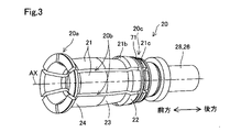
- FIG. 3 is a perspective view of the collet chuck 20 and the draw bolt 26.
- FIG. FIG. 4 is an enlarged sectional view of collet chuck 20 and draw bolt 26 in an unclamped state. In FIG. 4, the air flow is indicated by arrows.
- FIG. 5 is a front view of the collet chuck 20 in the unclamped state along the central axis AX. In FIG. 5, the inner periphery of the main shaft 10 and the outer periphery of the collet sleeve 30H along line IV-IV shown in FIG. 4 are indicated by dashed lines. The forward and rearward directions shown in FIGS. 3-5 are the same as those shown in FIG. As shown in FIG.
- the collet chuck 20 has an annular collet one end portion 20a forming one end, a plurality of collet gaps 20b, and a collet other end portion 20c forming the other end.
- the collet one end 20a is arranged closer to the tapered hole 10T than the collet other end 20c.
- the plurality of collet gaps 20b extend from the collet one end portion 20a toward the other end portion 10R side (FIG. 1), which is the other end side of the main shaft 10.
- a plurality of collet gaps 20b form a flow path that guides air to the tapered hole 10T.
- the collet chuck 20 has collet claws 21 as a plurality of claw portions.
- the collet chuck 20 has six collet claws 21 .
- a plurality of collet claws 21 are attached to the outer peripheral surface of one draw bolt end 27 (FIG. 4), which is the front end of the draw bolt 26, so as to surround the entire circumference of the draw bolt one end 27 (FIG. 4).
- a spool 25 is arranged inside the draw bolt 26 . The spool 25 is slidably fitted on the draw bolt 26 .
- the collet claw 21 generally has a shape obtained by dividing a cylinder into six sections along the central axis of the cylinder.
- Collet claw 21 has a shape extending along central axis AX of collet chuck 20 .
- the collet claw 21 includes a collet base portion 22, a collet cylindrical portion 23, a collet tip portion 24, a claw inclined surface 21a (FIG. 4), a first claw cam surface 21b as a collet cam surface, a collet concave portion 21c, and a collet concave portion 21c. It has a two-claw cam surface 21d.
- the collet base 22 is the rear end of the collet claw 21 .
- the collet tip 24 is the front end.
- the collet cylindrical portion 23 is positioned between the collet base portion 22 and the collet tip portion 24 .
- the thickness of the collet base portion 22 is thicker than the thickness of the collet cylindrical portion 23 .
- the inner peripheral surface of the collet base portion 22 protrudes inward from the inner peripheral surface of the collet cylindrical portion 23 .
- a claw slope 21a is provided at the boundary between the collet base portion 22 and the collet cylindrical portion 23. As shown in FIG.
- the outer peripheral surface of the collet base portion 22 protrudes outward from the outer peripheral surface of the collet cylindrical portion 23 .
- a first claw cam surface 21 b is provided on the outer peripheral surface of the collet claw 21 at the boundary between the collet base portion 22 and the collet cylindrical portion 23 .
- the claw slope 21a and the first claw cam surface 21b are surfaces that are inclined with respect to the central axis AX.
- the tip of the outer peripheral surface of the collet tip portion 24 protrudes toward the main shaft 10 with respect to the outer peripheral surface of the collet cylindrical portion 23 .
- a second pawl cam surface 21 d is provided on the outer peripheral surface of the collet tip portion 24 .
- the second pawl cam surface 21 d is a part of the surface that connects the protruding tip of the collet tip portion 24 and the collet cylindrical portion 23 .
- the second pawl cam surface 21d is inclined with respect to the central axis AX.
- An inner peripheral convex portion 24b is formed on the inner peripheral surface of the collet tip portion 24 and protrudes toward the central axis AX with respect to the inner peripheral surface of the collet cylindrical portion 23 .
- the inner peripheral protrusion 24b engages with a pull stud of a tool (not shown).
- the collet concave portion 21c is formed on the outer peripheral surface of the collet base portion 22 so as to be concave inward.
- the plurality of collet claws 21 are pressed against the draw bolt 26 by winding a coil spring 71 around each of the collet recesses 21c.
- a plurality of collet claws 21 are fixed at intervals in the circumferential direction.
- a plurality of collet claws 21 and draw bolts 26 are formed with a key structure (not shown) that fits together. As a result, the plurality of collet claws 21 are prevented from rotating with respect to the one end portion 27 of the draw bolt.
- a gap between two adjacent collet claws 21 is a collet gap 20b.
- the draw bolt 26 is formed with a bolt slope 26a at a position facing the pawl slope 21a.
- a main shaft cam surface 10M is formed on the collet sleeve 30H as a cam surface facing the first pawl cam surface 21b in the clamped state.
- the bolt slope 26a and the claw slope 21a are in contact with each other.
- the pull stud of the tool (not shown) is held by the inner peripheral convex portion 24b of the collet claw 21.
- the drawbar 30 moves forward, the first pawl cam surface 21b and the main shaft cam surface 10M come into contact with each other.
- a main shaft protrusion 10P is formed on the collet sleeve 30H at a position facing the second pawl cam surface 21d.
- the main shaft convex portion 10P is a portion of the main shaft cylindrical portion 10H that protrudes radially inward from the end adjacent to the tapered hole 10T.
- the storage space 10N of the spindle 10 is a space in which the collet base 22 is stored in the clamped state.
- the main shaft cam surface 10M is a partition surface that partitions the storage space 10N.
- the fourth air supply path 155 extends along the central axis AX direction.
- the spindle air supply path 156 extends along the radial direction of the spindle 10 . A downstream end of the spindle air supply path 156 opens into the storage space 10N.
- a plurality of spindle air supply paths 156 are provided at intervals in the circumferential direction of the spindle 10 .
- the spindle air supply path 156 is provided corresponding to the collet gap 20b.
- the number of spindle air supply paths 156 is six, which is the same as the number of collet gaps 20b.
- the internal space of the spool 25 is a sixth coolant channel 50 through which coolant flows.
- the plurality of collet gaps 20b are arranged at regular intervals in the circumferential direction.
- the plurality of spindle air supply paths 156 are arranged at regular intervals in the circumferential direction.
- the relative position of each of the six collet gaps 20b with respect to one spindle air supply path 156 is the same for all spindle air supply paths 156.
- the phase positions of the plurality of air supply paths 120 and the phase positions of the plurality of collet gaps 20b match.
- the phase position is the position in the circumferential direction of the spindle 10 .
- the tool When the tool is attached, the tool is inserted into the internal space of the collet chuck 20 and the drawbar 30 moves backward. In conjunction with this, the collet chuck 20 moves rearward and deforms to tighten the pull stud of the tool to grip the tool.
- the drawbar 30 moves forward. In conjunction with this, the collet chuck 20 moves forward, and the inner peripheral surface of the collet chuck 20 deforms away from the pull stud of the tool. The tool is withdrawn forward and a new tool is inserted.
- the spindle air supply path 156 opens into the storage space 10N.
- the air ejected from the spindle air supply path 156 temporarily stays in the storage space 10N and flows from the storage space 10N toward the tapered hole 10T.
- this reduces the deviation of the flow, so that the air can flow straight.
- the air flows through the collet gap 20b extending axially from the storage space 10N and is supplied to the tapered hole 10T. Since the air flows along the collet gap 20b, the air that flows out to the tapered hole 10T can be a straight flow.
- a plurality of spindle air supply paths 156 are provided. As a result, it is possible to suppress unevenness in the distribution of the air supplied to the storage space 10N, so that the air can be uniformly supplied through the plurality of collet gaps 20b. Further, in this embodiment, the relative positions of the plurality of collet gaps 20b with respect to one spindle air supply path 156 are the same for all spindle air supply paths 156. As shown in FIG. Furthermore, the number of multiple collet gaps 20b and the number of multiple spindle air supply paths 156 are the same. The multiple collet gaps 20b are arranged at regular intervals. Also, the plurality of spindle air supply paths 156 are arranged at regular intervals.
- phase positions of the plurality of spindle air supply paths 156 and the phase positions of the plurality of collet gaps 20b match.
- the air ejected from each spindle air supply passage 156 passes through the storage space 10N and smoothly flows into the nearest collet gap 20b, so that non-uniform air flow can be reduced. Disturbance can be reduced.
- the collet chuck 20 has a plurality of collet gaps 20b extending from the collet one end 20a toward the other end 10R of the main shaft 10.
- the main shaft cylindrical portion 10H has a plurality of air supply paths 120 for supplying air to the storage space 10N in the unclamped state.
- the air supplied to the spindle air supply path 156 temporarily stays in the storage space 10N, flows from the storage space 10N through the collet gap 20b, and is discharged from the tapered hole 10T. Since the air passes through the collet gap 20b and becomes a straight flow, it is possible to suppress the occurrence of a suction phenomenon in the vicinity of the central axis AX of the tapered hole 10T.
- the partition surface that partitions the storage space 10N has the main shaft cam surface 10M, air can be supplied to the storage space 10N having the main shaft cam surface 10M.
- the plurality of collet gaps 20b are gaps between the collet claws 21 of the plurality of collet claws 21 . This allows air to flow through the gaps between the collet claws 21 .
- each of the plurality of collet gaps 20b with respect to each of the plurality of spindle air supply passages 156 is the same. As a result, all the spindle air supply paths 156 have the same path from the spindle air supply path 156 to the collet gap 20b. Therefore, the flow of air ejected from the spindle air supply passage 156 is less likely to be biased, and the air can easily flow straight through the tapered hole 10T, thereby further suppressing the occurrence of the suction phenomenon.
- the number of multiple collet gaps 20b and the number of multiple spindle air supply paths 156 are the same.
- a plurality of collet gaps 20b are arranged at regular intervals.
- the plurality of spindle air supply paths 156 are arranged at regular intervals.
- the air ejected from the spindle air supply paths 156 is guided to the nearby collet gap 20b. Therefore, the air flow is less likely to be biased, the air flows straight, and the occurrence of the suction phenomenon can be suppressed.
- the phase positions of the plurality of spindle air supply paths 156 and the phase positions of the plurality of collet gaps 20b match.
- the spindle device 1 includes a disc spring 33 that biases the draw bar 30 and a cylinder device 15 that presses the disc spring 33 . Accordingly, the present application can be applied to the spindle device 1 including the disc spring 33 and the cylinder device 15 .
- the spindle device 1 includes an inner pipe 36, a downstream flow passage 35B arranged outside the inner pipe 36, a third coolant flow passage 38 arranged inside the inner pipe 36, and a sixth air supply passage. 126 and a fourth air supply path 155 . Accordingly, the present application can be applied to the spindle device 1 including the inner pipe 36, the downstream flow path 35B, the sixth air supply path 126, the fourth air supply path 155, and the third coolant flow path 38.
- phase positions of the multiple air supply paths 120 and the phase positions of the multiple collet gaps 20b match.
- a configuration may be adopted in which the phase positions of the plurality of spindle air supply paths 156 and the phase positions of the plurality of collet gaps 20b do not match. Even if the phase positions of the plurality of spindle air supply passages 156 and the phase positions of the plurality of collet gaps 20b are deviated from each other, the air ejected from the plurality of spindle air supply passages 156 travels through the same route. Since the air flows into the collet gap 20b, the air flow is less likely to be biased. Therefore, the air can flow straight, and the occurrence of the suction phenomenon can be reduced.
- a plurality of spindle air supply passages 156 are provided, but only one may be provided. Even in this manner, the air supplied from the spindle air supply path 156 to the storage space 10N is supplied to the plurality of collet gaps 20b by circulating in the circumferential direction through the storage space 10N.
- FIG. 6 is a first schematic diagram showing a cross-sectional view of the spindle device 11 of the second embodiment.
- FIG. 7 is a second schematic diagram showing a cross-sectional view of the spindle device 11 of the second embodiment. 6 is a diagram of the clamped state, and FIG. 7 is a diagram of the unclamped state.
- the main difference between the spindle device 11 and the spindle device 1 of the first embodiment is that the air supply passage 320 is formed radially outside the shaft hole 10J of the spindle 10 .
- the air supply passage 320 is positioned downstream of the upstream air supply passage 355 (FIG.
- the main shaft device 11 includes a cylindrical main shaft housing 3, a main shaft 10, a front side bearing 10A, a rear side bearing 10B, an electric motor 40, a draw bar 230, a collet chuck 20, and disc springs as biasing members. 33 , a cylinder device 15 and a control device 90 .
- the spindle housing 3 arranges the main elements of the spindle device 1 such as the spindle 10 and the electric motor 40 inside.
- the spindle housing 3 comprises a housing main body 17 that accommodates the electric motor 40 , a bearing housing 12 fixed to the other end of the housing main body 17 , and one housing end that is the front end (one end) of the main spindle housing 3 . and a cylindrical front cap 14 .
- the front cap 14 is fixed to the housing body 17 by bolts together with a first front outer ring retainer 61, which will be described later.
- the main shaft 10 has an axially extending shaft hole 10J including a tapered hole 10T and a main shaft cylindrical portion 10H as elements.
- the front side bearing 10A and the rear side bearing 10B rotatably support the main shaft 10 with respect to the main shaft housing 3 .
- the collet chuck 20 is arranged inside the spindle cylindrical portion 10H and is configured to be able to grip a tool.
- the front side bearing 10A and the rear side bearing 10B are angular rolling bearings.
- the front side bearing 10A is located on the front side of the electric motor 40 and is arranged at a position close to the one end portion 10F in the axial direction.
- the rear side bearing 10B is located on the rear side of the electric motor 40 and is arranged at a position close to the other end portion 10R in the axial direction.
- the draw bar 230 is connected to the collet other end of the collet chuck 20 and moves the collet chuck 20 back and forth along the axial direction.
- the draw bar 230 differs from the draw bar 30 in that it is not divided into an inner pipe and an outer pipe, unlike the first embodiment, and is a single pipe.
- the drawbar 230 has a rod hole 382H extending axially therethrough.
- the rod hole 382H communicates with the fourth coolant channel 47a of the fixed joint 47. As shown in FIG.
- the rod hole 382H forms a rod coolant channel 338 through which coolant supplied from the fourth coolant channel 47a flows.
- the coolant that has flowed through the rod coolant channel 338 passes through the inside of the tool and is supplied to the machining point, which is the edge of the tool located on the one end 10F side.
- the draw bar 230 has a draw bolt on one end side and a cylindrical spool disposed inside the draw bolt, as in the first embodiment. The inside of this cylindrical spool constitutes the downstream side of the rod coolant channel 338 .
- the collet chuck 20 in the second embodiment has the same configuration as the collet chuck 20 (FIG. 3) of the first embodiment.
- the main shaft cylindrical portion 10H has a storage space 10N in which the collet other end portion 20c (FIG. 3) is stored in the clamped state.
- the partition surface that partitions the storage space 10N is a spindle cam surface that contacts the first pawl cam surface 21b (FIG. 8) as a collet cam surface when the collet chuck 20 moves forward. 10M (FIG. 8).
- the spindle device 11 further has a front side member 234 and a rear side member 235 arranged on the outer peripheral side of the push rod 337 of the draw bar 230 .
- the front member 234 and the rear member 235 are each tubular.
- the front member 234 and the rear member 235 are spaced apart in the axial direction.
- a disk spring 33 is arranged in a compressed state between the front side member 234 and the rear side member 235 .
- the front end of the disc spring 33 contacts the front member 234 and the rear end of the disc spring 33 contacts the rear member 235 .
- the rear member 235 is fixed to the outer peripheral surface of the push rod 337 . Thereby, the rear member 235 interlocks with the push rod 337 .
- the front member 234 is arranged in the shaft hole 10J of the main shaft 3.
- the rear member 235 is pushed forward by the piston 18 .
- the push rod 337 advances in conjunction with the rear member 235, and the collet chuck 20 also advances.
- the collet chuck 20 moves forward, the collet claws 21 are opened within the shaft hole 10J, and the spindle device 11 is placed in an unclamped state.
- the advance and retraction of the piston 18 are performed by supplying working oil to the cylinder chamber and discharging the working oil from the cylinder chamber by the hydraulic device 93 provided in the main shaft device 11 .
- the hydraulic device 93 also includes the spindle device 1 of the first embodiment, but the illustration is omitted in the first embodiment.
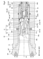
- FIG. 8 is a diagram showing the front side portion of the spindle device 11.
- FIG. 9 is a schematic diagram showing a part of the spindle device 11.
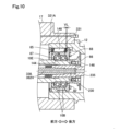
- FIG. 10 is a diagram showing a rear side portion of the spindle device 11.
- FIG. 8 and 9 are diagrams of when the spindle device 11 is in a clamped state. The configuration of the spindle device 11 will be further described with reference to FIGS. 8 to 10.
- FIG. 8 is a diagram showing the front side portion of the spindle device 11.
- FIG. 9 is a schematic diagram showing a part of the spindle device 11.
- FIG. 10 is a diagram showing a rear side portion of the spindle device 11.
- FIG. 8 and 9 are diagrams of when the spindle device 11 is in a clamped state. The configuration of the spindle device 11 will be further described with reference to FIGS. 8 to 10.
- FIG. 8 and 9 are diagrams of when the spindle device 11 is in a clamped state.
- the spindle device 11 further has a first front outer ring presser 61 , a second front outer ring presser 62 and a front inner ring presser 64 .
- the first front outer ring retainer 61 and the second front outer ring retainer 62 clamp the outer ring of the front bearing 10A in the axial direction, thereby restricting axial movement of the outer ring of the front bearing 10A.
- the second front outer ring retainer 62 is arranged on the inner peripheral surface of the housing body 17 .
- the first front outer ring retainer 61 is sandwiched between the housing body 17 and the front cap 14 and fixed in position.
- the front inner ring retainer 64 and the stepped surface 142 formed on the outer peripheral surface of the main spindle body 10E of the main spindle 10 clamp the inner ring of the front bearing 10A to prevent axial movement of the inner ring of the front bearing 10A. regulate.
- the front inner ring retainer 64 is sandwiched between the spindle body 10E and the spindle cap 10C that constitutes the spindle 10. As shown in FIG.
- the spindle device 11 further includes a sleeve 69 , a retainer plate 16 and a seal material 79 .
- the sleeve 69 has a cylindrical shape and is positioned radially between the front cap 14 and the spindle cap 10C.
- a sleeve 69 axially surrounds the spindle cap 10C.
- the sleeve 69 is axially movably disposed on the inner peripheral surface of the front cap 14 and, like the front cap 14, is a non-rotating element. As shown in FIG. 9, the outer circumference of the sleeve 69 is formed with a convex portion 69b that protrudes radially from the outer peripheral surface 69fa.
- the convex portion 69b is formed on the outer peripheral surface 69fa of the sleeve 69 along the circumferential direction.
- a rear end face of the convex portion 69b abuts on a stepped portion of the front cap 14.
- a third end surface 69e which is a front end surface of the convex portion 69b, abuts on a sealing member 79, which will be described later. Since this third end surface 69e is also a component of the convex portion 69b, it protrudes radially from the outer peripheral surface 69fa.
- the pressing plate 16 is disc-shaped and attached to the front cap 14 with bolts.
- a fourth end face 14 e which is the rear end face of the pressing plate 16 , abuts against the sealing material 79 .
- the third end surface 69e and the fourth end surface 14e face each other in the axial direction and sandwich the sealing material 79 therebetween.
- the sealing material 79 is positioned so as to enter the recess 14 b defined by the front cap 14 and the pressing plate 16 .
- the sleeve 69 further has a first end surface 69fb, which is an end surface on the other end (rear) side in the axial direction. Since the sleeve 69 is a non-rotating element, it can also be said that it is a component of the spindle housing 3 .
- the sealing material 79 is an annular elastic member arranged to surround the outer peripheral surface 69fa of the sleeve 69 .
- Synthetic rubber for example, is used as the sealing material 79 .
- the sealing material 79 is arranged in an axially compressed state between the third end surface 69e and the fourth end surface 14e. The sealing material 79 prevents the air flowing through the air supply path 320 from leaking to the outside.
- a spindle cap 10C forming a tapered hole 10T (Fig. 8) has a cap small diameter portion 10Cb located radially inside the front cap 14 and a cap large diameter portion 10Ca having an outer diameter larger than that of the cap small diameter portion 10Cb.
- the cap large-diameter portion 10Ca is located on the other end side (rear side) of the front cap 14 in the axial direction.
- the cap large-diameter portion 10Ca protrudes radially outward beyond the second minimum inner circumference of the first front outer ring presser 61 and the inner circumference of the sleeve 69 .
- the cap large-diameter portion 10Ca has a second end surface 10fb facing the first end surface 69fb of the sleeve 69 in the axial direction. In the clamped state, the first end face 69fb and the second end face 10fb are separated in the axial direction.
- the spindle device 11 further includes a first rear outer ring retainer 67, a second rear outer ring retainer 68, a rear inner ring retainer 66, a closing plate 65, and a preload spring 148.
- the closing plate 65 is disc-shaped and fixed to the inner peripheral surface of the bearing housing 12 .
- the bearing housing 12 is fixed to the other end of the housing body 17 .
- the bearing housing 12 is a component of the spindle housing 3 .
- the first rear outer ring retainer 67 and the second rear outer ring retainer 68 are fixed to each other by bolts 82 .
- the first rear outer ring retainer 67 and the second rear outer ring retainer 68 restrict axial movement of the outer ring of the rear bearing 10B.
- the rear inner ring retainer 66 is fastened to the main spindle body 10E by bolts 146. As shown in FIG. The second rear outer ring retainer 68 and the stepped surface 144 formed on the outer peripheral surface of the main shaft body 10E sandwich the inner ring of the rear bearing 10B, thereby restricting axial movement of the inner ring of the front bearing 10A. do.
- a preload spring 148 applies preload to the rear side bearing 10B and the front side bearing 10A.
- a plurality of preload springs 148 are arranged at regular intervals in the circumferential direction around the axial direction. One end of the preload spring 148 contacts the closing plate 65 and the other end of the preload spring 148 contacts the second rear outer ring retainer 68 .
- the second rear outer ring retainer 68 receives a rearward external force F from the preload spring 148, and is displaced rearward by the value VL in the clamped state as compared to the unclamped state. Further, the first rear outer ring retainer 67 integrated with the second rear outer ring retainer 68 by the bolt 82 is also displaced rearward by the value VL, so that the outer ring of the rear bearing 10B is pushed rearward. be Thereby, pressurization is applied to the rear side bearing 10B and the front side bearing 10A. Note that the value VL is 0.2 mm in this embodiment.
- the rear member 235 and the drawbar 230 are pushed forward by the piston 18 .
- the main shaft 10 is slightly displaced forward by receiving the forward thrust of the piston 18 against the pressing force of the disc spring 33 .
- the main shaft 10 is displaced forward by 0.2 mm in the unclamped state rather than in the clamped state.
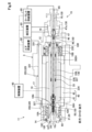
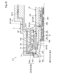
- FIG. 11 shows the spindle device 11 in an unclamped state.
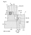
- FIG. 12 is a schematic diagram of part of the spindle device 11 shown in FIG. Regarding the air supply path 320, the upstream side and the downstream side are based on the air flow direction.
- An upstream end portion 331 of the air supply path 320 is formed at the rear end portion of the spindle housing 3 (specifically, the housing main body 17).
- the air supply device 92 communicates with the upstream end 331 via a flow pipe.
- the air supply device 92 feeds pressurized air into the air supply path 320 via the upstream end portion 331 .
- the air supply passage 320 includes, in order from the upstream side to the downstream side, an air communication passage 321 (FIGS. 8 and 10) including an upstream end portion 331, and a spindle air supply passage connected to the downstream end portion of the air communication passage 321.
- 327 FIG. 8
- the downstream end of the spindle air supply path 327 opens into the storage space 10N.
- the air that has flowed into the storage space 10N from the spindle air supply path 327 temporarily stays in the storage space 10N, and then flows from the storage space 10N toward the tapered hole 10T through the collet gap 20b.
- the number of spindle air supply paths 327 is one.
- the air supplied from the spindle air supply path 327 to the storage space 10N flows through the storage space 10N formed along the circumferential direction and flows into the six collet gaps 20b (FIG. 3).
- the air communication path 321 is formed radially outside the main shaft air supply path 327 .
- the air communication passage 321 consists of, in order from the upstream side to the downstream side, an upstream side communication passage 321A formed in the main shaft housing 3 and the first front outer ring retainer 61, which are non-rotating elements. , one end side flow path 321B formed across the bearing housing 12 which is a non-rotating element and the main shaft 10 which is a rotating element, and a downstream side communication path 321C which is formed in the main shaft 10 which is a rotating element and the front inner ring presser 64. and have An upstream air supply path 355 (FIG.
- the downstream side air supply path 356 (FIG. 6) is formed by the flow path formed in the main shaft 10 in the one end side flow path 321B, the downstream communication path 321C, and the main shaft air supply path 327. is formed.
- the flow path formed in the front cap 14 and the sleeve 69 which are non-rotating elements, is referred to as one end side first flow path 321Ba, and is a rotating element.
- a channel formed in the main shaft 10 is called a one-end-side second channel 321Bc.
- the one-end-side first flow path 321Ba is a flow path extending in a radial direction perpendicular to the axial direction.
- the one-end-side second flow path 321Bc has a flow path extending axially and a flow path extending radially within the spindle cap 10C.
- the upstream communication passage 321A is formed across the housing body 17, the first front outer ring retainer 61, and the front cap 14, as shown in FIG.
- the upstream communication passage 321A allows the air that has flowed in from the upstream end portion 331 (FIG. 10) to flow to the inside of the front cap 14 located on the front side of the front bearing 10A.
- the one-end flow path 321B is located closer to the one end 10F than the front bearing 10A in the axial direction.
- an axial flow path 321Bb is formed by the downstream portion of the one end side first flow path 321Ba and the upstream side portion of the one end side second flow path 321Bc.
- the axial flow path 321Bb extends in the axial direction.
- the axial flow path 321Bb is composed of, in order from the upstream side to the downstream side, an upstream axial flow path 323 that is a downstream portion of the one end side first flow path 321Ba and an upstream side of the one end side second flow path 321Bc. and a downstream axial flowpath 324 which is a portion.
- An upstream axial passage 323 is formed in the sleeve 69 of the non-rotating element.
- the downstream axial flow path 324 is formed in the spindle cap 10C, which is a rotating element. As shown in FIG.
- the upstream axial flow path 323 and the downstream axial flow path 324 face each other with a small gap in the axial direction.
- a downstream end of the upstream axial flow path 323 is a first opening 69fp formed in the first end surface 69fb.
- the upstream end of the downstream axial flow path 324 is a second opening 10fp formed in the second end face 10fb.
- the second opening 10fp is formed by a circumferential groove 10fv formed in the second end surface 10fb in the circumferential direction.
- the downstream axial flow path 324 is formed by the circumferential groove 10fv and an end flow path 328 extending axially from the circumferential groove 10fv.
- the control device 90 supplies air to the air supply path 320 by operating the air supply device 92 in the clamped state. As a result, air blows out from the first opening 69fp to form an airflow between the first end surface 69fb and the second end surface 10fb, thereby causing the coolant supplied to the machining point to flow between the first end surface 69fb and the second end surface 10fb. Intrusion into the interior through the gap with the second end surface 10fb can be suppressed.
- the cylinder device 15 advances the spindle 10 including the spindle cap 10C in a direction approaching the first end face 69fb.
- the second end surface 10fb is moved.
- the first end surface 69fb and the second end surface 10fb are in contact with each other.
- the rotational phase position of the main shaft 10 is controlled so that the upstream axial flow path 323 and the downstream axial flow path 324 are aligned in the axial direction.
- the upstream axial flow path 323 and the downstream axial flow path 324 are connected in the unclamped state, thereby communicating the axial flow path 321Bb. Air flows from the upstream side to the downstream side of the axial flow path 321Bb.
- the first end face 69fb is also slightly displaced forward.
- the seal material 79 is compressed in the axial direction, so it biases the sleeve 69 toward the second end surface 10fb.
- the first end surface 69fb and the second end surface 10fb of the sleeve 69 are brought into close contact with each other, thereby suppressing leakage of air from the axial flow path 321Bb to the outside. Also, since the first end surface 69fb and the second end surface 10fb are in close contact with each other due to the elastic force of the sealing member 79, the amount of wear of the first end surface 69fb and the second end surface 10fb can be reduced.
- the downstream communication passage 321C has a first downstream communication passage 321Ca and a second downstream communication passage 321Cb in order from upstream to downstream.
- the first downstream communication channel 321Ca extends in the axial direction.
- the first downstream communication passage 321Ca is formed across the spindle cap 10C, the front inner ring retainer 64, and the main spindle body 10E.
- the second downstream communication channel 321Cb extends radially.
- a downstream end of the second downstream communication passage 321Cb is connected to the main shaft air supply passage 327 .
- the air that flows from the second downstream communication passage 321Cb to the spindle air supply passage 327 flows into the storage space 10N.
- the air that has flowed into the storage space 10N flows straight through the collet gap 20b.
- the above-described second embodiment having the same configuration as that of the above-described first embodiment has the same effect.
- the air supplied to the storage space 10N passes through the collet gap 20b and becomes a straight flow, it is possible to suppress the occurrence of the suction phenomenon near the central axis AX of the tapered hole 10T.
- the air communication passage 321 including the one end passage 321B is formed radially outside the main shaft air supply passage 327, the main shaft air supply passage of the main shaft 10 is 327 in the radial direction, for example, in the case where the air communication passage 321 is formed in the shaft hole 10J of the main shaft 10, the configuration of the main shaft device 1 can be suppressed from becoming complicated.
- the drawbar 230 since there is no need to form the air communication path 321 in the drawbar 230, the drawbar 230 does not need to have a double pipe structure. Further, by forming a part of the air communication passage 321 in the front cap 14 and the spindle cap 10C, it is possible to easily assemble the front cap 14 and the spindle cap 10C. can be formed to Further, by forming the one-end-side passage 321B in the spindle housing 3 and the spindle 10, there is no need to newly use another member for forming the one-end-side passage 321B. According to the second embodiment, as shown in FIG.
- an axial flow path 321Bb extending over the main shaft housing 3 and the main shaft 10 can be formed.
- FIG. 13 is a first diagram for explaining another embodiment of the second embodiment.
- FIG. 14 is a second diagram for explaining another embodiment of the second embodiment.
- FIG. 13 is a diagram corresponding to FIG. 11 and showing an unclamped state.
- FIG. 14 is a diagram corresponding to FIG. 12 and shows the one end side flow path 321B in the unclamped state.
- the one end side flow path 321B has an axial flow path 321Bb that straddles the non-rotating element and the rotating element.
- the flow path is not limited to the axial flow path 321Bb.
- FIG. 12 is a first diagram for explaining another embodiment of the second embodiment.
- FIG. 14 is a second diagram for explaining another embodiment of the second embodiment.
- FIG. 13 is a diagram corresponding to FIG. 11 and showing an unclamped state.
- FIG. 14 is a diagram corresponding to FIG. 12 and shows the one end side flow path 321B in the unclamped state.
- the one end side flow path 321B has
- the flow path extending over the non-rotating element and the rotating element may be a radial flow path 421Bb extending in the radial direction.
- a spindle device 111 shown in FIG. 13 does not have a sleeve 69, a seal member 79, and a pressing plate 16 unlike the spindle device 11 of the second embodiment shown in FIG.
- the front cap 14 of the spindle housing 3 has a one end side housing inner peripheral surface 3fc in which an inner peripheral surface opening 3fr forming the one end side flow path 321B is formed.
- the one end side housing inner peripheral surface 3fc is located on the front side (one end side) of the inner peripheral surface of the spindle housing 3 relative to the front side bearing 10A.
- the spindle cap 10C of the main shaft 10 has a one end main shaft outer peripheral surface 10fc in which an outer peripheral surface opening 10fr forming the one end flow path 321B is formed.
- the one end side main shaft outer peripheral surface 10fc is located on the front side (one end side) of the outer peripheral surface of the main shaft 10 relative to the front side bearing 10A.
- the control device 90 controls the rotational phase position of the main shaft 10 so that the outer peripheral surface opening 10fr is arranged at a position facing the inner peripheral surface opening 69fr in the radial direction.
- the cap large-diameter portion 10Ca and the front cap 14 are spaced apart in the axial direction. To position.
- the one end channel 321B includes an inner peripheral surface opening 3fr and an outer peripheral surface opening 10fr, and functions as a radial direction channel 421Bb extending in the radial direction.
- the radial flow path 421Bb has an upstream radial flow path 423 and a downstream radial flow path 424 in order from upstream to downstream.
- the upstream radial flow path 423 is formed in the front cap 14 .
- a downstream end of the upstream radial flow path 423 is an inner peripheral surface opening 3fr.
- a downstream radial channel 424 is formed in the spindle cap 10C.
- the upstream end of the downstream radial flow path 424 is the outer peripheral surface opening 10fr.
- a boundary portion between the upstream radial flow passage 423 and the downstream radial flow passage 424 in the radial flow passage 421Bb is formed by a gap between the one end housing inner peripheral surface 3fc and the one end spindle outer peripheral surface 10fc.
- a gap (both side gap) between the one end side housing inner peripheral surface 3fc and the one end side spindle outer peripheral surface 10fc is also formed on both sides in the axial direction of the boundary portion of the radial flow path 421Bb.
- the gaps on both sides have flow path resistance to the extent that the air flowing through the radial flow path 421Bb can be prevented from leaking to the outside.
- the flow path extending over the spindle housing 3, which is a non-rotating element, and the spindle 10, which is a rotating element can be formed as the radial flow path 421Bb.
- the spindle device 11 may include the axial flow path 321Bb and the radial flow path 421Bb.
- the present disclosure is not limited to the above-described embodiments, and can be implemented in various configurations without departing from the scope of the present disclosure.
- the technical features of the embodiments corresponding to the technical features in each form described in the outline of the invention are used to solve some or all of the above problems, or Alternatively, replacements and combinations can be made as appropriate to achieve all. Also, if the technical features are not described as essential in this specification, they can be deleted as appropriate.
- Collet base 23 ... Collet cylindrical portion 24 ... Collet tip 25 ... Spool 24b ... Inner peripheral convex portion 26 ... Draw bolt 26a ... Bolt slope 27 ... Draw bolt one end 28 ... Draw bolt other end, 30... Draw bar 30A... Outer peripheral side draw bar 30D, 30I... Large diameter portion 30F... One end of draw bar 30G... Guide sleeve 30H... Collet sleeve 30R... Other end of draw bar 31H... First rod hole 32H... Second rod hole 33 Disc spring 34 Collar 35 Second air supply path 35A Upstream flow path 35B Downstream flow path 35C Other end air flow path 35D One end air flow path , 36... inner pipe, 36A... one end of pipe, 36B... other end of pipe, 37...
- Control device 92 Air supply device 93... Hydraulic device 95... Coolant supply device 111... Spindle device 120... Air supply path 125... Third air supply path 126... Third 6 air supply paths 130 coolant flow path 142 step surface 144 step surface 146 bolt 148 preload spring 155 fourth air supply path 156 spindle air supply path 230 draw bar 234 Front member 235 Rear member 320 Air supply path 321 Air communication path 321A Upstream communication path 321B One end flow path 321Ba One end first flow path 321Bb Shaft directional flow path 321Bc one end side second flow path 321C downstream communication path 321Ca first downstream communication flow path 321Cb second downstream communication flow path 323 upstream axial flow path 324...
- Downstream axial flow path 327... Main shaft air supply path, 328... End flow path, 331... Upstream end, 337... Push rod, 338... Rod coolant flow path, 355... Upstream air supply path, 356 Downstream air supply paths 355, 382H Rod hole 421Bb Radial flow path 423 Upstream radial flow path 424 Downstream radial flow path AX Central axis R2 Area
Landscapes
- Engineering & Computer Science (AREA)
- Mechanical Engineering (AREA)
- Gripping On Spindles (AREA)
- Turning (AREA)
- Machine Tool Units (AREA)
Priority Applications (5)
| Application Number | Priority Date | Filing Date | Title |
|---|---|---|---|
| US18/685,283 US20250332644A1 (en) | 2021-09-28 | 2022-09-21 | Spindle device |
| CN202280057729.5A CN117881497A (zh) | 2021-09-28 | 2022-09-21 | 主轴装置 |
| JP2023551358A JP7779323B2 (ja) | 2021-09-28 | 2022-09-21 | 主軸装置 |
| DE112022004610.4T DE112022004610T5 (de) | 2021-09-28 | 2022-09-21 | Spindelvorrichtung |
| PCT/JP2022/035078 WO2023054083A1 (ja) | 2021-09-28 | 2022-09-21 | 主軸装置 |
Applications Claiming Priority (2)
| Application Number | Priority Date | Filing Date | Title |
|---|---|---|---|
| JP2021157621 | 2021-09-28 | ||
| JP2021-157621 | 2021-09-28 |
Publications (1)
| Publication Number | Publication Date |
|---|---|
| WO2023053471A1 true WO2023053471A1 (ja) | 2023-04-06 |
Family
ID=85782140
Family Applications (2)
| Application Number | Title | Priority Date | Filing Date |
|---|---|---|---|
| PCT/JP2022/001553 Ceased WO2023053471A1 (ja) | 2021-09-28 | 2022-01-18 | 主軸装置 |
| PCT/JP2022/035078 Ceased WO2023054083A1 (ja) | 2021-09-28 | 2022-09-21 | 主軸装置 |
Family Applications After (1)
| Application Number | Title | Priority Date | Filing Date |
|---|---|---|---|
| PCT/JP2022/035078 Ceased WO2023054083A1 (ja) | 2021-09-28 | 2022-09-21 | 主軸装置 |
Country Status (5)
| Country | Link |
|---|---|
| US (1) | US20250332644A1 (https=) |
| JP (1) | JP7779323B2 (https=) |
| CN (1) | CN117881497A (https=) |
| DE (1) | DE112022004610T5 (https=) |
| WO (2) | WO2023053471A1 (https=) |
Families Citing this family (1)
| Publication number | Priority date | Publication date | Assignee | Title |
|---|---|---|---|---|
| CN118577827B (zh) * | 2024-08-07 | 2024-10-22 | 常州赢世智能装备有限公司 | 一种无单独静压轴承零件的静压主轴 |
Citations (4)
| Publication number | Priority date | Publication date | Assignee | Title |
|---|---|---|---|---|
| JPS58109246A (ja) * | 1981-12-21 | 1983-06-29 | Toshiba Mach Co Ltd | 立旋盤の主軸構造 |
| JPH10180509A (ja) * | 1996-12-26 | 1998-07-07 | Okuma Mach Works Ltd | 工作機械の主軸装置 |
| JPH1133874A (ja) * | 1997-07-23 | 1999-02-09 | Nikken Kosakusho:Kk | スピンドルの切削液、空気通路 |
| JP2001096438A (ja) * | 1999-09-28 | 2001-04-10 | Nippei Toyama Corp | 主軸装置 |
Family Cites Families (1)
| Publication number | Priority date | Publication date | Assignee | Title |
|---|---|---|---|---|
| JP7347175B2 (ja) | 2019-12-04 | 2023-09-20 | 株式会社ジェイテクト | 主軸装置 |
-
2022
- 2022-01-18 WO PCT/JP2022/001553 patent/WO2023053471A1/ja not_active Ceased
- 2022-09-21 CN CN202280057729.5A patent/CN117881497A/zh active Pending
- 2022-09-21 DE DE112022004610.4T patent/DE112022004610T5/de active Pending
- 2022-09-21 WO PCT/JP2022/035078 patent/WO2023054083A1/ja not_active Ceased
- 2022-09-21 US US18/685,283 patent/US20250332644A1/en active Pending
- 2022-09-21 JP JP2023551358A patent/JP7779323B2/ja active Active
Patent Citations (4)
| Publication number | Priority date | Publication date | Assignee | Title |
|---|---|---|---|---|
| JPS58109246A (ja) * | 1981-12-21 | 1983-06-29 | Toshiba Mach Co Ltd | 立旋盤の主軸構造 |
| JPH10180509A (ja) * | 1996-12-26 | 1998-07-07 | Okuma Mach Works Ltd | 工作機械の主軸装置 |
| JPH1133874A (ja) * | 1997-07-23 | 1999-02-09 | Nikken Kosakusho:Kk | スピンドルの切削液、空気通路 |
| JP2001096438A (ja) * | 1999-09-28 | 2001-04-10 | Nippei Toyama Corp | 主軸装置 |
Also Published As
| Publication number | Publication date |
|---|---|
| JP7779323B2 (ja) | 2025-12-03 |
| JPWO2023054083A1 (https=) | 2023-04-06 |
| CN117881497A (zh) | 2024-04-12 |
| DE112022004610T5 (de) | 2024-07-11 |
| US20250332644A1 (en) | 2025-10-30 |
| WO2023054083A1 (ja) | 2023-04-06 |
Similar Documents
| Publication | Publication Date | Title |
|---|---|---|
| KR100298065B1 (ko) | 공구홀더및이러한공구홀더내에절삭공구를장착하기위한방법 | |
| KR100482976B1 (ko) | 공작기계의 주축장치 | |
| US7972096B2 (en) | Spindle device of machine tool | |
| US5584618A (en) | Pneumatically actuated drill motor and an associated method and apparatus for clamping the drill motor to a drill plate | |
| US20140154024A1 (en) | High-frequency spindle | |
| JP5522537B2 (ja) | 加工装置 | |
| JP4982253B2 (ja) | コンビネーションホルダ | |
| US5775853A (en) | Machining method and multi-function tool | |
| WO2023053471A1 (ja) | 主軸装置 | |
| JP2005313311A (ja) | 主軸装置及びそれに用いる工具ホルダクランプユニット | |
| KR101840161B1 (ko) | 초고속 에어베어링 스핀들 | |
| CN114227457B (zh) | 一种磨床 | |
| CN108533569B (zh) | 一种带保压功能的回转油缸 | |
| JP3841631B2 (ja) | 工作機械の主軸装置 | |
| KR102376454B1 (ko) | Cnc 초소형 복합자동선반 스핀들의 척킹장치 | |
| JP3549638B2 (ja) | 工具 | |
| JP2007307651A (ja) | 主軸装置 | |
| JPWO2023054083A5 (https=) | ||
| CN110248770B (zh) | 机床的主轴装置 | |
| EP1549451B1 (en) | Tool with selectively biased member and method for forming a non -axis symmetric feature | |
| JP2005081489A (ja) | 工作機械における主軸装置の工具ホルダ嵌合部の清掃方法及びその装置 | |
| JP2009107037A (ja) | 旋盤の主軸構造 | |
| CN2920487Y (zh) | 主轴装置及在该装置中使用的工具保持器夹紧单元 | |
| JP2007307679A (ja) | 主軸装置 | |
| JP2006102868A (ja) | 切削加工装置 |
Legal Events
| Date | Code | Title | Description |
|---|---|---|---|
| 121 | Ep: the epo has been informed by wipo that ep was designated in this application |
Ref document number: 22875355 Country of ref document: EP Kind code of ref document: A1 |
|
| NENP | Non-entry into the national phase |
Ref country code: DE |
|
| 122 | Ep: pct application non-entry in european phase |
Ref document number: 22875355 Country of ref document: EP Kind code of ref document: A1 |
|
| NENP | Non-entry into the national phase |
Ref country code: JP |