WO2023048076A1 - 揮発性脂肪酸の検知方法および測定装置 - Google Patents
揮発性脂肪酸の検知方法および測定装置 Download PDFInfo
- Publication number
- WO2023048076A1 WO2023048076A1 PCT/JP2022/034697 JP2022034697W WO2023048076A1 WO 2023048076 A1 WO2023048076 A1 WO 2023048076A1 JP 2022034697 W JP2022034697 W JP 2022034697W WO 2023048076 A1 WO2023048076 A1 WO 2023048076A1
- Authority
- WO
- WIPO (PCT)
- Prior art keywords
- electrodes
- fatty acids
- volatile fatty
- humidity
- measuring
- Prior art date
- Legal status (The legal status is an assumption and is not a legal conclusion. Google has not performed a legal analysis and makes no representation as to the accuracy of the status listed.)
- Ceased
Links
Images




Classifications
-
- G—PHYSICS
- G01—MEASURING; TESTING
- G01N—INVESTIGATING OR ANALYSING MATERIALS BY DETERMINING THEIR CHEMICAL OR PHYSICAL PROPERTIES
- G01N27/00—Investigating or analysing materials by the use of electric, electrochemical, or magnetic means
- G01N27/02—Investigating or analysing materials by the use of electric, electrochemical, or magnetic means by investigating impedance
- G01N27/04—Investigating or analysing materials by the use of electric, electrochemical, or magnetic means by investigating impedance by investigating resistance
- G01N27/12—Investigating or analysing materials by the use of electric, electrochemical, or magnetic means by investigating impedance by investigating resistance of a solid body in dependence upon absorption of a fluid; of a solid body in dependence upon reaction with a fluid, for detecting components in the fluid
-
- G—PHYSICS
- G01—MEASURING; TESTING
- G01N—INVESTIGATING OR ANALYSING MATERIALS BY DETERMINING THEIR CHEMICAL OR PHYSICAL PROPERTIES
- G01N27/00—Investigating or analysing materials by the use of electric, electrochemical, or magnetic means
- G01N27/02—Investigating or analysing materials by the use of electric, electrochemical, or magnetic means by investigating impedance
- G01N27/04—Investigating or analysing materials by the use of electric, electrochemical, or magnetic means by investigating impedance by investigating resistance
- G01N27/06—Investigating or analysing materials by the use of electric, electrochemical, or magnetic means by investigating impedance by investigating resistance of a liquid
- G01N27/07—Construction of measuring vessels; Electrodes therefor
-
- G—PHYSICS
- G01—MEASURING; TESTING
- G01N—INVESTIGATING OR ANALYSING MATERIALS BY DETERMINING THEIR CHEMICAL OR PHYSICAL PROPERTIES
- G01N27/00—Investigating or analysing materials by the use of electric, electrochemical, or magnetic means
- G01N27/02—Investigating or analysing materials by the use of electric, electrochemical, or magnetic means by investigating impedance
- G01N27/04—Investigating or analysing materials by the use of electric, electrochemical, or magnetic means by investigating impedance by investigating resistance
- G01N27/045—Circuits
- G01N27/046—Circuits provided with temperature compensation
-
- G—PHYSICS
- G01—MEASURING; TESTING
- G01N—INVESTIGATING OR ANALYSING MATERIALS BY DETERMINING THEIR CHEMICAL OR PHYSICAL PROPERTIES
- G01N33/00—Investigating or analysing materials by specific methods not covered by groups G01N1/00 - G01N31/00
- G01N33/0004—Gaseous mixtures, e.g. polluted air
- G01N33/0009—General constructional details of gas analysers, e.g. portable test equipment
- G01N33/0027—General constructional details of gas analysers, e.g. portable test equipment concerning the detector
- G01N33/0036—General constructional details of gas analysers, e.g. portable test equipment concerning the detector specially adapted to detect a particular component
- G01N33/0047—Organic compounds
-
- G—PHYSICS
- G01—MEASURING; TESTING
- G01N—INVESTIGATING OR ANALYSING MATERIALS BY DETERMINING THEIR CHEMICAL OR PHYSICAL PROPERTIES
- G01N33/00—Investigating or analysing materials by specific methods not covered by groups G01N1/00 - G01N31/00
- G01N33/48—Biological material, e.g. blood, urine; Haemocytometers
- G01N33/483—Physical analysis of biological material
- G01N33/487—Physical analysis of biological material of liquid biological material
- G01N33/48707—Physical analysis of biological material of liquid biological material by electrical means
-
- G—PHYSICS
- G01—MEASURING; TESTING
- G01N—INVESTIGATING OR ANALYSING MATERIALS BY DETERMINING THEIR CHEMICAL OR PHYSICAL PROPERTIES
- G01N27/00—Investigating or analysing materials by the use of electric, electrochemical, or magnetic means
- G01N27/02—Investigating or analysing materials by the use of electric, electrochemical, or magnetic means by investigating impedance
- G01N27/04—Investigating or analysing materials by the use of electric, electrochemical, or magnetic means by investigating impedance by investigating resistance
- G01N27/12—Investigating or analysing materials by the use of electric, electrochemical, or magnetic means by investigating impedance by investigating resistance of a solid body in dependence upon absorption of a fluid; of a solid body in dependence upon reaction with a fluid, for detecting components in the fluid
- G01N27/122—Circuits particularly adapted therefor, e.g. linearising circuits
- G01N27/123—Circuits particularly adapted therefor, e.g. linearising circuits for controlling the temperature
- G01N27/124—Circuits particularly adapted therefor, e.g. linearising circuits for controlling the temperature varying the temperature, e.g. in a cyclic manner
-
- G—PHYSICS
- G01—MEASURING; TESTING
- G01N—INVESTIGATING OR ANALYSING MATERIALS BY DETERMINING THEIR CHEMICAL OR PHYSICAL PROPERTIES
- G01N27/00—Investigating or analysing materials by the use of electric, electrochemical, or magnetic means
- G01N27/02—Investigating or analysing materials by the use of electric, electrochemical, or magnetic means by investigating impedance
- G01N27/04—Investigating or analysing materials by the use of electric, electrochemical, or magnetic means by investigating impedance by investigating resistance
- G01N27/12—Investigating or analysing materials by the use of electric, electrochemical, or magnetic means by investigating impedance by investigating resistance of a solid body in dependence upon absorption of a fluid; of a solid body in dependence upon reaction with a fluid, for detecting components in the fluid
- G01N27/125—Composition of the body, e.g. the composition of its sensitive layer
Definitions
- the present invention relates to a detection method and measuring device for volatile fatty acids.
- VFA Volatile fatty acids
- propionic acid propionic acid
- butyric acid acetic acid
- acetic acid Volatile fatty acids
- cows digest their food they emit a large amount of methane gas, which contributes to global warming, but this amount can be greatly reduced by controlling VFA in the cow rumen (rumen).
- rumen cow rumen
- the object of the present invention is to detect VFA with high sensitivity and to provide a method and apparatus for measuring it with high accuracy.
- the reference data is data obtained by measuring the electrical characteristics using the sample when the relative humidity in the space near the electrodes is in a humidity condition in which dew condensation does not occur between the electrodes, or data obtained by measuring the volatile Using a reference sample containing no fatty acid or a reference sample containing a certain proportion of volatile fatty acid, the relative humidity in the space near the electrodes satisfies the humidity conditions immediately before dew condensation occurs between the electrodes.
- composition 1 The method for detecting volatile fatty acids according to configuration 1, which is the obtained data.
- Composition 3 The method for detecting volatile fatty acids according to Configuration 1 or Configuration 2, wherein the humidity condition is that the relative humidity is 80% or more and less than 100%.
- Composition 4 The method for detecting volatile fatty acids according to configuration 3, wherein the relative humidity is 80% or more and 95% or less.
- Composition 5 5. The volatile fatty acid according to any one of configurations 1 to 4, wherein the electrodes have a configuration in which the first thin line electrodes and the second thin line electrodes are alternately arranged in at least a partial region on the insulating substrate. detection method.
- composition 6 The method for detecting volatile fatty acids according to configuration 5, wherein the first thin wire electrodes and the second thin wire electrodes are alternately arranged at regular intervals.
- Composition 7 The method for detecting volatile fatty acids according to configuration 6, wherein the interval is 100 nm or more and 1000 nm or less.
- Composition 8) A first metal is formed on at least a part of the exposed surface of the first fine wire electrode, and a second metal different from the first metal is formed on at least a part of the exposed surface of the second fine wire electrode. is formed and 8.
- Composition 9 9.
- composition 8 The method of detecting volatile fatty acids according to configuration 8, wherein said first metal is selected from the group consisting of gold, platinum, silver, titanium and alloys thereof, and carbon.
- Configuration 10 The volatile according to configuration 8 or 9, wherein said second metal is selected from the group consisting of silver, copper, iron, zinc, nickel, cobalt, aluminum, tin, chromium, molybdenum, manganese, magnesium and alloys thereof.
- Method for detecting fatty acids Composition 11
- Composition 12 12.
- composition 13 The method for detecting volatile fatty acids according to any one of configurations 1 to 11, wherein the relative humidity is controlled by a temperature adjustment device thermally connected to the resistance measurement device.
- Composition 13 The method for detecting volatile fatty acids according to configuration 12, wherein the temperature control device is a Peltier element.
- composition 14 14. The method for detecting volatile fatty acids according to any one of configurations 1 to 13, wherein the form of the sample is an aqueous solution.
- Composition 15 comprising a resistance measuring device, a humidity measuring means, a data extracting means and a data analyzing means;
- the resistance measuring device has at least two or more electrodes arranged adjacent to each other with a fine interval on an insulating substrate, measures the electrical characteristics caused by the electrical resistance between the electrodes, and outputs the results.
- the humidity measuring means is arranged adjacent to the resistance measuring device, measures the relative humidity in the space near the electrodes of the resistance measuring device, and outputs the result
- the data extracting means is means for extracting output data from the resistance measuring device when the relative humidity measured by the humidity measuring means satisfies a predetermined humidity condition
- the data analysis means is means for comparing the data extracted by the data extraction means with calibration curve data obtained in advance and outputting the result.
- composition 16 16. The apparatus for measuring volatile fatty acids according to configuration 15, wherein the electrodes have a configuration in which first fine wire electrodes and second fine wire electrodes are alternately arranged in at least a partial region on the insulating substrate.
- Composition 17 17. The apparatus for measuring volatile fatty acids according to configuration 16, wherein the first thin wire electrodes and the second thin wire electrodes are alternately arranged at regular intervals.
- Composition 18 18. The device for measuring volatile fatty acids according to configuration 17, wherein the interval is 100 nm or more and 1000 nm or less.
- composition 19 A first metal is formed on at least a part of the exposed surface of the first fine wire electrode, and a second metal different from the first metal is formed on at least a part of the exposed surface of the second fine wire electrode. is formed and 19. Measurement of volatile fatty acids according to any one of configurations 16 to 18, wherein the resistance measuring device measures a current flowing between the first thin wire electrode and the second thin wire electrode and outputs the result.
- the humidity measuring means comprises humidity measuring electrodes for determining humidity based on the electrical resistance between the electrodes, and the material constituting the humidity measuring electrodes constitutes the first thin wire electrode or the second thin wire electrode. 20.
- FIG. 1 is a schematic configuration diagram for explaining the configuration of a VFA detection and measurement device according to the present invention
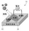
- BRIEF DESCRIPTION OF THE DRAWINGS It is structural drawing explaining the structure of a resistance measuring device (galvanic sensor), (a) is a top view, (b) is sectional drawing. It is an explanatory view explaining the principle of operation in case a resistance measuring device is a galvanic sensor.
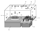
- FIG. 2 is an explanatory diagram for explaining a method for detecting and measuring VFA according to the present invention; It is an explanatory view explaining the method of the present invention based on the time change of the sensor output and the platinum resistance obtained by using the prototype VFA detection and measurement system.
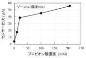
- FIG. 6 is a characteristic diagram showing the propionic acid concentration dependency of the sensor output shown in FIG. 5;
- FIG. 6 is a characteristic diagram showing the propionic acid concentration dependency of the sensor output shown in FIG. 5;
- a sample that may contain VFA is placed together with a resistance measurement device in a closed space in which water vapor exists, and the space near the electrodes provided in the resistance measurement device is The output from the resistance measuring device is monitored when the humidity meets the humidity conditions just before condensation occurs between the electrodes.
- the resistance measuring device measures an electrical characteristic (either electrical resistance, conductivity, or current value) caused by electrical resistance between at least two or more electrodes that are adjacently arranged on an insulating substrate with a fine interval. and the output from the resistance measuring device shall be the measurement result of the electrical property.
- a specific example of such a resistance measuring device has two or more electrodes exposed on an insulating substrate so as to be in contact with the outside air (in the present invention, the steam atmosphere in the closed space is intended), At least two different metals are used as materials for the electrodes, and a galvanic sensor that measures a galvanic current flowing between the electrodes can be mentioned.
- a galvanic sensor is disclosed, for example, in US Pat.
- two or more electrodes exposed to the outside air are provided on an insulating substrate, and the electrodes are made of the same material.
- a resistance measuring sensor, etc. in which a circuit is provided and a resistance value is measured from the circuit, can also be used.
- the galvanic sensor is characterized by its small size and does not necessarily require an external power supply, and can be used particularly favorably. The details of the aspect of using a galvanic sensor as a resistance measuring device in the VFA detection and measurement method of the present invention will be described later.
- the inventors have found that the electrical characteristics caused by the electrical resistance between the electrodes of the resistance measuring device in a state where the VFA exists in a water vapor atmosphere are the relative humidity of the space near the electrodes just before condensation occurs between the electrodes. It was found that the output from the resistance measuring device depends on the concentration of VFA in the atmosphere, and that VFA can be detected with high sensitivity and quantified with high accuracy when measured when the conditions are satisfied. On the other hand, when the electrical characteristics due to the electrical resistance between the electrodes are measured in a state where dew condensation occurs between the electrodes of the resistance measurement device, the output from the resistance measurement device is reduced until the space between the electrodes is completely filled with the liquid consisting of water and VFA.
- the relative humidity of the space near the electrodes of the resistance measuring device is preferably 80% or more and less than 100%, more preferably 80% or more and 95% or less.
- the space near the electrodes of the resistance measuring device means a space containing at least the outside air in contact with the electrodes of the device in the closed space where the resistance measuring device is placed, and typically the space around the device.
- a space containing atmosphere is intended. Specifically, for example, by arranging any humidity measuring means in a closed space adjacent to the resistance measuring device, it is possible to measure the relative humidity in the space near the electrodes of the resistance measuring device. .
- the detection and measurement of VFA according to the present invention are believed to be based on the following mechanism.
- the location where the target electrical characteristics are measured by the resistance measuring device that is, the resistance measurement
- water molecules derived from water vapor and VFA volatilized from the sample and floating in the atmosphere in the closed space are co-adsorbed.
- the ionized protons (H + ) become carriers, which move in a hopping manner via water molecules and adsorbed VFAs, changing the electrical resistance (which can be called conductivity) between the electrodes. .
- the surface is in a state where many (frequently) adsorption phenomena of water molecules derived from water vapor can occur. Such a state is generally considered to occur over a certain time range (time interval) rather than at a certain point in time (instantaneous).
- the electrical resistance between the electrodes is calculated using the same sample as the measurement result obtained under the above conditions when the relative humidity is a humidity condition in which dew condensation does not occur between the electrodes.
- VFA in the sample can be detected by comparing the data obtained by measurement.
- the relative humidity that is, immediately before condensation occurs between the electrodes, the relative humidity It is also possible to detect VFAs in the sample by comparing the data obtained by measuring the electrical resistance between the electrodes (when the humidity condition of 1000 ) is satisfied.
- the amount of protons described above is highly and monotonically dependent on the amount of VFA, it is possible to determine (quantify) the amount of VFA in the sample using a calibration curve.
- the surface of the insulating substrate is preferably hydrophilic.
- the use of an insulating substrate with a hydrophilic surface promotes the co-adsorption of water molecules and VFAs, improving the detection sensitivity and measurement accuracy of VFAs, as well as improving the stability and reproducibility of output data from resistance measurement equipment. do.
- that the surface is hydrophilic means that the contact angle of water on the surface is 0° or more and 50° or less.
- FIG. 1 shows the configuration of the VFA detection and measurement apparatus of the present invention.
- the VFA detection and measurement device 101 of the present invention comprises a resistance measurement device 11 , humidity measurement means 12 , data extraction means 13 and data analysis means 14 .
- Output data from the resistance measuring device 11 and the humidity measuring means 12 are sent to the data extracting means 13 via the signal line 15 .
- the output data from the resistance measuring device 11 when a predetermined humidity condition is satisfied, which is extracted by the data extraction means 13, is sent to the data analysis means 14 via another signal line, and the data is converted into data.
- the analytical means 14 compares the data with previously obtained calibration curve data and the like to confirm the presence or absence of VFA in the sample 16 and/or quantify the VFA.
- the resistance measuring device 11 and the humidity measuring means 12 are placed together with the sample 16 in a closed space 17 in which water vapor exists.
- the resistance measuring device 11 includes a substrate (insulating substrate) 21 , a first thin wire electrode 22 , a second thin wire electrode 23 , a first electrode (first collector electrode) 24 and a second electrode (second collector electrode) 25 .
- the first fine wire electrode 22 and the second fine wire electrode 23 are arranged adjacent to each other on the insulating substrate 21 with a fine gap therebetween.
- the resistance measuring device 11 measures electrical characteristics resulting from the electrical resistance between the first thin wire electrode 22 and the second thin wire electrode 23 .
- the first fine line-shaped electrodes 22 and the second fine line-shaped electrodes 23 are arranged alternately in at least a part of the insulating substrate 21 .
- the facing surfaces of the first thin wire electrode 22 and the second thin wire electrode 23 are widened, the sensitivity to VFA is increased, and the stability (reproducibility) of the obtained results is improved. get higher
- the first fine line-shaped electrodes 22 and the second fine line-shaped electrodes 23 are alternately arranged at regular intervals, that is, the values of d1 and d2 in the sectional view of FIG. and have no in-plane distribution (constant in the plane).
- this interval is constant, the VFA detection and measurement mechanism according to the present invention described above functions effectively, and the change in electrical resistance between the first fine-line electrode 22 and the second fine-line electrode 23 becomes steep. As a result, detection sensitivity improves, and measurement accuracy also increases.
- first thin wire electrode 22 and the second thin wire electrode 23 are made of the same conductive material, and a voltage is applied between both electrodes via the first electrode 24 and the second electrode 25, so that the first electrode 24 and the second electrode 25 may be used as a resistance measurement sensor that measures electrical resistance by measuring the current flowing between them, or the first thin wire electrode 22 and the second thin wire electrode 23 are made of different metals, A galvanic sensor that measures electrical resistance by measuring a galvanic current flowing between the first electrode 24 and the second electrode 25 may be used.
- the first thin wire electrode 22 and the first electrode 24 may be made of the same conductive material or may be made of different conductive materials. The same applies to the second thin wire electrode 23 and the second electrode 25 .
- the resistance measuring device 11 is a galvanic sensor.
- a first thin wire electrode 22 and a second thin wire electrode 23 made of different metals (metals A and B) are arranged side by side on an insulating substrate.
- It is a current detection type sensor that utilizes the phenomenon that a galvanic current flows between the electrodes when a conductive droplet such as a water droplet touches a pair of electrodes.
- the galvanic sensor 11 includes a first thin wire electrode 22 made of a first metal and a second metal or semiconductor made of a second metal different from the first metal.
- Two thin wire electrodes 23 are juxtaposed on the insulating substrate 21 .
- the first fine line-shaped electrode 22 and the second fine line-shaped electrode 23 are arranged adjacent to each other on the insulating substrate 21 with a fine gap therebetween.
- the distance between the first thin wire electrode 22 and the second thin wire electrode 23 detects VFA with high sensitivity, and From the viewpoint of measuring with high accuracy, it is preferably 100 nm or more and 1000 nm or less.
- a silicon substrate having an oxide film ( SiO.sub.2 film) formed on its surface can be preferably used, but it is not limited to a silicon substrate.
- a wide variety of insulating materials can also be used.
- the substrate body is a conductor such as metal, by forming an insulating coating or coating thereon, the relationship between the first fine wire electrode 22 and the second fine wire electrode 23 can be improved.
- the first fine wire electrode 22 is connected to the first electrode 24
- the second fine wire electrode 23 is connected to the second electrode 25
- the electrical current connected to the first electrode 24 and the second electrode 25 is connected to the first electrode 24 and the second electrode 25 .
- An electrical signal is transmitted to the data extraction means 13 via wiring (not shown).
- an amplifier may be connected to the first electrode 24 and the second electrode 25 to amplify the galvanic current and transmit an electric signal to the data extraction means 13 .
- a space may be provided between the first fine-line electrode 22 and the second fine-line electrode 23, or an insulator may be embedded therein.
- the surface is preferably hydrophilic so that water molecules can easily be adsorbed.
- first metal and a second metal having a different electrochemical potential are used, and the gap between the metals is equal to or greater than a certain level due to water molecules and VFA. In the co-adsorption state with a density of current flows.
- the length of the adjacent portion between the thin line electrodes (hereinafter referred to as parallel running distance) can be increased, for example, by a comb structure or a double spiral structure. be able to.
- parallel running distance the length of the adjacent portion between the thin line electrodes
- the structure itself for maximizing the parallel running distance of two wirings within a certain planar area is well known in the field of semiconductor devices and the like, such a structure may also be adopted as necessary.
- "arranging thin line electrodes in parallel on a substrate” does not specify the mutual orientation of a plurality of thin line electrodes placed on the substrate, but rather, the thin line electrodes are spaced apart on the same plane of the substrate. It means to place
- the material of the first thin wire electrode 22 includes, for example, gold (Au), platinum (Pt), silver (Ag), titanium (Ti) and alloys thereof, and Carbon (C) and allotropes thereof may be mentioned.
- the second fine wire electrode 23 is used as an anode, examples of the material of the second fine wire electrode 23 include silver (Ag), copper (Cu), iron (Fe), zinc (Zn), nickel (Ni), Mention may be made of cobalt (Co), aluminum (Al), tin (Sn), chromium (Cr), molybdenum (Mo), manganese (Mn), magnesium (Mg) and alloys thereof.
- the second fine wire electrodes 23 are made of materials other than silver and its alloys.
- the output (galvanic current value) of the galvanic sensor 11 depends on the combination of metal materials used for the first fine wire electrode 22 and the second fine wire electrode 23 .
- the silver/iron combination has a higher corrosion rate per the same area, resulting in a higher galvanic current value.
- the gold/silver electrode wears less and has a longer life.
- silver since silver has the effect of preventing the galvanic sensor 11 from being moldy, it is preferably used as the first fine wire electrode 22 or the second fine wire electrode 23 .
- the first electrode 24 and the second electrode 25 are made of the same material as the first thin wire electrode 22 and the second thin wire electrode 23, respectively, because the manufacturing process of the galvanic sensor 11 is simplified.
- the metal of the anode electrode which is the second fine wire electrode 23 is ionized, and the anode electrode (second fine wire electrode) is gradually consumed.
- the thickness of the anode electrode is increased, or the width of the anode electrode is increased, and instead the width of the cathode electrode (first thin wire electrode) is increased. For example, it can be made narrower.
- the interval between the fine wire electrodes is made very short, a slight increase in the interval between the fine wire electrodes due to consumption of the anode electrode has a large effect on the measurement result of electrical resistance (galvanic current).
- the humidity measuring means 12 is arranged adjacent to the resistance measuring device 11, and is a portion (hereinafter referred to as In a similar context, it is simply referred to as a “measurement unit”.), that is, in the vicinity of two or more thin wire electrodes of the resistance measuring device 11.
- a humidity measurement means there are resistance change type humidity sensors that measure the amount of moisture absorbed by dry and wet materials such as polymers and ceramics as electrical resistance, and capacitance sensors that use polymer films as dry and wet response materials. and a method using a temperature sensor and a humidity conversion system that monitors the temperature as a saturated steam environment and obtains the converted humidity.
- the first thin wire electrode 22 and the second A method of placing a platinum electrode near the fine wire electrode 23, monitoring the temperature from the resistance value of the platinum electrode, and determining the converted humidity can be preferably used.
- the temperature measuring section of the humidity measuring means 12 adopting the above method can be easily provided in the resistance measuring device 11. is possible, and there is an advantage that the whole VFA detection and measurement apparatus of the present invention can be miniaturized and the cost can be reduced.
- the data extracting means 13 has a function of extracting output data from the resistance measuring device 11 and sending it to the data analyzing means 14 when the relative humidity measured by the humidity measuring means 12 satisfies a predetermined humidity condition.
- the predetermined humidity condition regarding the relative humidity the relative humidity is preferably 80% or more and less than 100%, more preferably 80% or more and 95% or less, as described above.
- the relative humidity in the space near the electrodes of the resistance measurement device 11 measured by the humidity measurement means 12 is 80% or more and 100%. Less than is preferable, and 80% or more and 95% or less is more preferable.
- VFA can be detected with high sensitivity and can be measured with high accuracy.
- the data analysis means 14 extracts the output data of the resistance measuring device 11 sent via the data extracting means 13 (measurement data of galvanic current when the resistance measuring device 11 is a galvanic sensor), and the data obtained in advance. It compares with the calibration curve data obtained and outputs the amount of VFA corresponding to the output data, or outputs the presence or absence of VFA in the sample 16 from which the output data is obtained by comparing with a predetermined threshold value.
- VFA detection and measurement A specific embodiment of VFA detection and measurement according to the present invention will be further described with reference to FIG.
- a sample 16 made of a VFA aqueous solution is placed on a base 41 together with a resistance measuring device 11 in a closed space 17 made of an acrylic box or the like.
- Water (water vapor) 31 and VFA 32 transpired from the resistance measuring device 11 are configured to be able to reach the measuring portion (at least the portion including the electrodes).
- the humidity measuring means 12 is arranged adjacent to the resistance measuring device 11, and is configured to be able to measure the relative humidity in the vicinity of the electrodes of the resistance measuring device 11.
- FIG. Here, in the system shown in FIG.
- the temperature adjustment device 42 is arranged under the resistance measurement device 11, the resistance measurement device 11 and the temperature adjustment device 42 are thermally connected, and the temperature adjustment device 42 controls the resistance measurement device 11, more precisely, by adjusting the temperature of the measuring section of the resistance measuring device 11, the relative humidity in the space near the electrodes existing in the measuring section is preferably configured to be controllable.
- a Peltier device or the like can be used as the temperature adjustment device 42 .
- the temperature adjusting device 42 and the resistance measuring device 11 are connected thermally by a heat pump.
- the temperature of the resistance measurement device 11 is controlled by the temperature adjustment device 42.
- the relative humidity in the vicinity of the electrodes present in the measurement unit is set to satisfy the humidity conditions immediately before dew condensation occurs between the electrodes, specifically, the relative humidity is set to 80% or more and less than 100%. Alternatively, the relative humidity can be efficiently controlled to be 80% or more and 95% or less.
- Example 1 In Example 1, the results of fabricating the VFA detection and measurement system shown in FIG. 4 and examining its characteristics will be described. However, it should be noted that the present invention is of course not limited to such a particular form, and the scope of the present invention is defined by the appended claims.
- the resistance measuring device 11 was a galvanic sensor in which a first thin wire electrode 22 and a second thin wire electrode 23 were arranged in parallel in a comb shape on an insulating substrate 21 as shown in FIG.
- the material of the first thin wire electrode 22 was aluminum
- the material of the second thin wire electrode 23 was gold.
- Each of the first fine-line electrode 22 and the second fine-line electrode 23 has a line width of 2 ⁇ m, a height of 200 nm, and a length of 1300 ⁇ m. be.
- the number of pairs consisting of the first thin wire electrode 22 and the second thin wire electrode 23 is 92 pieces.
- a Si wafer on which a thermal oxide film with a thickness of 100 nm was formed was used as the substrate 21 .
- the contact angle of water on the flat portion of the substrate 21 is 33°, and the surface is hydrophilic.
- the humidity measuring means 12 the temperature is monitored from the resistance value of the platinum electrode, and the converted humidity is obtained therefrom.
- a Peltier element was used as the temperature control device 42 .
- As the sample 16 a propionic acid aqueous solution with five concentrations (0 mM, 10 mM, 20.7 mM, 100 mM and 207 mM) was used. The amount of aqueous solution is 50 mL each in common.
- a closed space 17 was provided by a polypropylene resin box. The capacity of the closed space 17 is 430 mL, and the shortest distance between the container holding the sample 16 and the resistance measuring device 11 is about 3 cm.
- the elapsed time of 600-800 s is zone 1a
- the elapsed time of 1500-1700 s is zone 1b.
- the relative humidity in zone 1a is estimated to be 85%
- the relative humidity in zone 1b is estimated to be 92%. It was confirmed to be within the preferred range of conditions.
- the sample with a propionic acid concentration of 0 mM and the sample with a propionic acid concentration of 10 mM have almost the same sensor output after an elapsed time of about 1950 s, and the 20.7 mM sample has a sensor output of 100 mM after an elapsed time of 1900 s.
- the 207 mM sample is exceeded, and after an elapsed time of about 2300 s, the sensor output with the 100 mM sample exceeds the sensor output with the 207 mM sample.
- Zone 1a has a steep characteristic curve at a propionic acid concentration of 20 mM or less and a relatively gentle characteristic curve at a propionic acid concentration of 20 mM or more
- Zone 1b has a steep characteristic curve at a propionic acid concentration of 20 mM or less and a saturated characteristic curve at a propionic acid concentration of 20 mM or more. From this characteristic curve, it can be seen that a low concentration of propionic acid (VFA) such as 10 mM can be detected and measured with sufficiently high linearity.
- VFA propionic acid
- VFA is a substance that greatly affects the productivity and quality improvement of dairy farming such as cattle, and is also closely related to the emission of methane gas through the digestion of food by cattle. It is matter. Therefore, if VFA is detected with high sensitivity, measured with high accuracy, and the results are fed back, the productivity and quality of dairy farming can be greatly improved, and it is believed that this will greatly contribute to the prevention of global warming.
- the method of the present invention which detects VFA with high sensitivity and measures it with high accuracy, leads to quantitative evaluation of the activity of anaerobic bacteria, quality control in feed production, monitoring of methane fermentation tanks, and final disposal. It can be expected to be widely used in various cases where VFA is generated by microbial decomposition, such as landfill operation management and environmental management of paddy fields and lake water.
Landscapes
- Chemical & Material Sciences (AREA)
- Health & Medical Sciences (AREA)
- Life Sciences & Earth Sciences (AREA)
- Physics & Mathematics (AREA)
- Engineering & Computer Science (AREA)
- General Health & Medical Sciences (AREA)
- Pathology (AREA)
- Immunology (AREA)
- General Physics & Mathematics (AREA)
- Analytical Chemistry (AREA)
- Biochemistry (AREA)
- Biomedical Technology (AREA)
- Electrochemistry (AREA)
- Chemical Kinetics & Catalysis (AREA)
- Food Science & Technology (AREA)
- Medicinal Chemistry (AREA)
- Urology & Nephrology (AREA)
- Molecular Biology (AREA)
- Hematology (AREA)
- Biophysics (AREA)
- Combustion & Propulsion (AREA)
- Investigating Or Analyzing Materials By The Use Of Electric Means (AREA)
- Investigating Or Analyzing Materials By The Use Of Fluid Adsorption Or Reactions (AREA)
Priority Applications (3)
| Application Number | Priority Date | Filing Date | Title |
|---|---|---|---|
| EP22872830.9A EP4407308A4 (en) | 2021-09-21 | 2022-09-16 | DETECTION METHOD AND MEASURING DEVICE FOR VOLATILE FATTY ACID |
| US18/692,013 US20250130193A1 (en) | 2021-09-21 | 2022-09-16 | Method for sensing volatile fatty acid and device for measuring volatile fatty acid |
| JP2023549520A JP7743103B2 (ja) | 2021-09-21 | 2022-09-16 | 揮発性脂肪酸の検知方法および測定装置 |
Applications Claiming Priority (2)
| Application Number | Priority Date | Filing Date | Title |
|---|---|---|---|
| JP2021153071 | 2021-09-21 | ||
| JP2021-153071 | 2021-09-21 |
Publications (1)
| Publication Number | Publication Date |
|---|---|
| WO2023048076A1 true WO2023048076A1 (ja) | 2023-03-30 |
Family
ID=85720701
Family Applications (1)
| Application Number | Title | Priority Date | Filing Date |
|---|---|---|---|
| PCT/JP2022/034697 Ceased WO2023048076A1 (ja) | 2021-09-21 | 2022-09-16 | 揮発性脂肪酸の検知方法および測定装置 |
Country Status (4)
| Country | Link |
|---|---|
| US (1) | US20250130193A1 (https=) |
| EP (1) | EP4407308A4 (https=) |
| JP (1) | JP7743103B2 (https=) |
| WO (1) | WO2023048076A1 (https=) |
Cited By (2)
| Publication number | Priority date | Publication date | Assignee | Title |
|---|---|---|---|---|
| WO2025063276A1 (ja) * | 2023-09-22 | 2025-03-27 | 国立研究開発法人物質・材料研究機構 | 酢酸ガス濃度測定装置、その使用方法、および酢酸ガス濃度の測定方法 |
| WO2025094861A1 (ja) * | 2023-11-01 | 2025-05-08 | 国立研究開発法人物質・材料研究機構 | 蒸散計測センサ、蒸散計測装置および蒸散計測方法 |
Citations (5)
| Publication number | Priority date | Publication date | Assignee | Title |
|---|---|---|---|---|
| JP2010002335A (ja) * | 2008-06-20 | 2010-01-07 | New Cosmos Electric Corp | ガス検知素子 |
| WO2016013544A1 (ja) | 2014-07-23 | 2016-01-28 | 国立研究開発法人物質・材料研究機構 | 高速応答・高感度乾湿応答センサー |
| JP2017509874A (ja) * | 2014-02-21 | 2017-04-06 | ドレーガー セイフティー アクチエンゲゼルシャフト ウント コンパニー コマンディートゲゼルシャフト アウフ アクチエン | 電気化学ガスセンサ |
| WO2017213118A1 (ja) * | 2016-06-08 | 2017-12-14 | 国立研究開発法人物質・材料研究機構 | 露点測定方法及び露点測定装置 |
| JP2019066427A (ja) * | 2017-10-04 | 2019-04-25 | 山形県 | 湿度センサ及びその製造方法 |
-
2022
- 2022-09-16 EP EP22872830.9A patent/EP4407308A4/en not_active Withdrawn
- 2022-09-16 US US18/692,013 patent/US20250130193A1/en active Pending
- 2022-09-16 WO PCT/JP2022/034697 patent/WO2023048076A1/ja not_active Ceased
- 2022-09-16 JP JP2023549520A patent/JP7743103B2/ja active Active
Patent Citations (5)
| Publication number | Priority date | Publication date | Assignee | Title |
|---|---|---|---|---|
| JP2010002335A (ja) * | 2008-06-20 | 2010-01-07 | New Cosmos Electric Corp | ガス検知素子 |
| JP2017509874A (ja) * | 2014-02-21 | 2017-04-06 | ドレーガー セイフティー アクチエンゲゼルシャフト ウント コンパニー コマンディートゲゼルシャフト アウフ アクチエン | 電気化学ガスセンサ |
| WO2016013544A1 (ja) | 2014-07-23 | 2016-01-28 | 国立研究開発法人物質・材料研究機構 | 高速応答・高感度乾湿応答センサー |
| WO2017213118A1 (ja) * | 2016-06-08 | 2017-12-14 | 国立研究開発法人物質・材料研究機構 | 露点測定方法及び露点測定装置 |
| JP2019066427A (ja) * | 2017-10-04 | 2019-04-25 | 山形県 | 湿度センサ及びその製造方法 |
Non-Patent Citations (2)
| Title |
|---|
| See also references of EP4407308A4 |
| TERADA, HIDEFUMI ET AL.: "Behavior in sensors that measure humidity separately that reach relative humidity 100% +/-", THE SURFACE FINISHING SOCIETY OF JAPAN KOEN TAIKAI KOEN YOSHISHU, THE SURFACE FINISHING SOCIETY OF JAPAN, JP, vol. 141, 20 February 2020 (2020-02-20), JP , pages 92 - 93, XP009545115, ISSN: 0917-2947 * |
Cited By (2)
| Publication number | Priority date | Publication date | Assignee | Title |
|---|---|---|---|---|
| WO2025063276A1 (ja) * | 2023-09-22 | 2025-03-27 | 国立研究開発法人物質・材料研究機構 | 酢酸ガス濃度測定装置、その使用方法、および酢酸ガス濃度の測定方法 |
| WO2025094861A1 (ja) * | 2023-11-01 | 2025-05-08 | 国立研究開発法人物質・材料研究機構 | 蒸散計測センサ、蒸散計測装置および蒸散計測方法 |
Also Published As
| Publication number | Publication date |
|---|---|
| EP4407308A1 (en) | 2024-07-31 |
| JPWO2023048076A1 (https=) | 2023-03-30 |
| EP4407308A4 (en) | 2025-09-17 |
| US20250130193A1 (en) | 2025-04-24 |
| JP7743103B2 (ja) | 2025-09-24 |
Similar Documents
| Publication | Publication Date | Title |
|---|---|---|
| WO2023048076A1 (ja) | 揮発性脂肪酸の検知方法および測定装置 | |
| Mitzner et al. | Development of a micromachined hazardous gas sensor array | |
| CN101842689A (zh) | 基于暴露材料的渐进腐蚀的湿度传感器 | |
| CN105474003B (zh) | 气体浓度检测装置 | |
| KR20190040074A (ko) | 환경 민감성 박막 장치의 에너지 펄스 제거 | |
| Jain et al. | Novel bismuth/multi-walled carbon nanotubes-based electrochemical sensor for the determination of neuroprotective drug cilostazol | |
| JP6898605B2 (ja) | 露点測定方法及び露点測定装置 | |
| CN101636654A (zh) | 油总酸值测量装置与寿命估算装置及利用该装置进行的油总酸值与油传感器测量方法 | |
| US11913892B2 (en) | Condensation detection element | |
| US20200256826A1 (en) | Pulse-driven capacitive detection for field-effect transistors | |
| Khan et al. | Wide range and highly linear signal processed systematic humidity sensor array using Methylene Blue and Graphene composite | |
| JP6786918B2 (ja) | ガスセンサアレイ、ガス測定装置、及びガス測定方法 | |
| US8950240B2 (en) | Acetone gas sensor apparatus | |
| JPWO2023048076A5 (https=) | ||
| JP7477932B2 (ja) | 熱中症、脱水症予兆警告システムおよび蒸散速度計測用デバイス | |
| CN109612921B (zh) | 一种腐蚀监测传感器及其制备方法 | |
| US20060180466A1 (en) | Method and apparatus for providing an electrochemical sensor at an elevated temperature | |
| KR20180039075A (ko) | 인코딩된 바이오센서들 및 그 제조 및 사용 방법들 | |
| CN201043961Y (zh) | 温度补偿蒸汽传感器 | |
| Shrestha et al. | Continuously activated function of aluminum in galvanic micro arrays in contact with water | |
| JP2008216008A5 (https=) | ||
| JP2007046914A (ja) | 油の酸性、塩基性度検出用基準電極 | |
| WO2025063276A1 (ja) | 酢酸ガス濃度測定装置、その使用方法、および酢酸ガス濃度の測定方法 | |
| US20240369526A1 (en) | Integrated printed sensor patch for micro-climate monitoring of greenhouse and soil-related variables | |
| JP4969577B2 (ja) | 電気化学セルの出力のためのスケールファクター |
Legal Events
| Date | Code | Title | Description |
|---|---|---|---|
| 121 | Ep: the epo has been informed by wipo that ep was designated in this application |
Ref document number: 22872830 Country of ref document: EP Kind code of ref document: A1 |
|
| WWE | Wipo information: entry into national phase |
Ref document number: 2023549520 Country of ref document: JP |
|
| WWE | Wipo information: entry into national phase |
Ref document number: 18692013 Country of ref document: US |
|
| WWE | Wipo information: entry into national phase |
Ref document number: 2022872830 Country of ref document: EP |
|
| NENP | Non-entry into the national phase |
Ref country code: DE |
|
| ENP | Entry into the national phase |
Ref document number: 2022872830 Country of ref document: EP Effective date: 20240422 |
|
| WWP | Wipo information: published in national office |
Ref document number: 18692013 Country of ref document: US |
|
| WWW | Wipo information: withdrawn in national office |
Ref document number: 2022872830 Country of ref document: EP |