WO2023048051A1 - Piezoelectric vibration device - Google Patents
Piezoelectric vibration device Download PDFInfo
- Publication number
- WO2023048051A1 WO2023048051A1 PCT/JP2022/034441 JP2022034441W WO2023048051A1 WO 2023048051 A1 WO2023048051 A1 WO 2023048051A1 JP 2022034441 W JP2022034441 W JP 2022034441W WO 2023048051 A1 WO2023048051 A1 WO 2023048051A1
- Authority
- WO
- WIPO (PCT)
- Prior art keywords
- sealing member
- vibration device
- piezoelectric vibration
- vibrator
- piezoelectric
- Prior art date
Links
- 238000007789 sealing Methods 0.000 claims abstract description 280
- 239000000758 substrate Substances 0.000 claims abstract description 96
- 229920005989 resin Polymers 0.000 claims abstract description 62
- 239000011347 resin Substances 0.000 claims abstract description 62
- 230000001681 protective effect Effects 0.000 claims description 97
- 239000000463 material Substances 0.000 claims description 50
- 230000002093 peripheral effect Effects 0.000 claims description 29
- 230000010355 oscillation Effects 0.000 claims description 9
- 238000000465 moulding Methods 0.000 abstract description 57
- 239000003822 epoxy resin Substances 0.000 description 42
- 229920000647 polyepoxide Polymers 0.000 description 42
- 239000013078 crystal Substances 0.000 description 27
- 238000005452 bending Methods 0.000 description 22
- 230000005284 excitation Effects 0.000 description 21
- 239000002184 metal Substances 0.000 description 9
- 229910052751 metal Inorganic materials 0.000 description 9
- 230000000149 penetrating effect Effects 0.000 description 9
- 239000011521 glass Substances 0.000 description 7
- 239000000919 ceramic Substances 0.000 description 6
- 238000012986 modification Methods 0.000 description 6
- 230000004048 modification Effects 0.000 description 6
- 229920001187 thermosetting polymer Polymers 0.000 description 5
- PXHVJJICTQNCMI-UHFFFAOYSA-N Nickel Chemical compound [Ni] PXHVJJICTQNCMI-UHFFFAOYSA-N 0.000 description 4
- 239000000853 adhesive Substances 0.000 description 4
- 230000001070 adhesive effect Effects 0.000 description 4
- 229920001721 polyimide Polymers 0.000 description 4
- 239000009719 polyimide resin Substances 0.000 description 4
- 239000003566 sealing material Substances 0.000 description 4
- 239000000470 constituent Substances 0.000 description 3
- 229910052710 silicon Inorganic materials 0.000 description 3
- 239000010703 silicon Substances 0.000 description 3
- 229920001169 thermoplastic Polymers 0.000 description 3
- 239000004416 thermosoftening plastic Substances 0.000 description 3
- 239000003795 chemical substances by application Substances 0.000 description 2
- 230000014509 gene expression Effects 0.000 description 2
- 239000011810 insulating material Substances 0.000 description 2
- 239000012212 insulator Substances 0.000 description 2
- 229910052759 nickel Inorganic materials 0.000 description 2
- 238000007747 plating Methods 0.000 description 2
- 238000005476 soldering Methods 0.000 description 2
- IJGRMHOSHXDMSA-UHFFFAOYSA-N Atomic nitrogen Chemical compound N#N IJGRMHOSHXDMSA-UHFFFAOYSA-N 0.000 description 1
- RYGMFSIKBFXOCR-UHFFFAOYSA-N Copper Chemical compound [Cu] RYGMFSIKBFXOCR-UHFFFAOYSA-N 0.000 description 1
- 239000004696 Poly ether ether ketone Substances 0.000 description 1
- PNEYBMLMFCGWSK-UHFFFAOYSA-N aluminium oxide Inorganic materials [O-2].[O-2].[O-2].[Al+3].[Al+3] PNEYBMLMFCGWSK-UHFFFAOYSA-N 0.000 description 1
- 239000002131 composite material Substances 0.000 description 1
- 239000004020 conductor Substances 0.000 description 1
- 229910052802 copper Inorganic materials 0.000 description 1
- 239000010949 copper Substances 0.000 description 1
- 229910001873 dinitrogen Inorganic materials 0.000 description 1
- 239000013013 elastic material Substances 0.000 description 1
- 229920006351 engineering plastic Polymers 0.000 description 1
- 239000011261 inert gas Substances 0.000 description 1
- 238000002347 injection Methods 0.000 description 1
- 239000007924 injection Substances 0.000 description 1
- 229910000833 kovar Inorganic materials 0.000 description 1
- 239000007769 metal material Substances 0.000 description 1
- 238000000034 method Methods 0.000 description 1
- 229920006122 polyamide resin Polymers 0.000 description 1
- 229920002530 polyetherether ketone Polymers 0.000 description 1
- 239000000843 powder Substances 0.000 description 1
- 239000010453 quartz Substances 0.000 description 1
- VYPSYNLAJGMNEJ-UHFFFAOYSA-N silicon dioxide Inorganic materials O=[Si]=O VYPSYNLAJGMNEJ-UHFFFAOYSA-N 0.000 description 1
- 238000005245 sintering Methods 0.000 description 1
- 229910000679 solder Inorganic materials 0.000 description 1
Images


Classifications
-
- H—ELECTRICITY
- H01—ELECTRIC ELEMENTS
- H01L—SEMICONDUCTOR DEVICES NOT COVERED BY CLASS H10
- H01L25/00—Assemblies consisting of a plurality of individual semiconductor or other solid state devices ; Multistep manufacturing processes thereof
-
- H—ELECTRICITY
- H03—ELECTRONIC CIRCUITRY
- H03H—IMPEDANCE NETWORKS, e.g. RESONANT CIRCUITS; RESONATORS
- H03H9/00—Networks comprising electromechanical or electro-acoustic devices; Electromechanical resonators
- H03H9/02—Details
Definitions
- the present invention relates to piezoelectric vibration devices.
- a piezoelectric vibration device includes, for example, a crystal oscillator using a crystal vibrating piece.
- the crystal oscillator includes a crystal vibrating piece that is a piezoelectric element, a holding member that holds the crystal vibrating piece, and a lid member that seals the holding member.
- the crystal vibrating piece is held in the box-shaped holding member made of an insulating material such as ceramic.
- the crystal oscillator is sealed by a lid member in a state in which the electrodes of the crystal vibrating piece and the electrodes in the holding member are joined.
- a piezoelectric vibration device is expensive because the lid member made of metal or glass is joined to the holding member made of ceramic. Further, in the piezoelectric vibration device, the box-shaped holding member and the lid member are overlapped, so that the thickness of the piezoelectric vibration device increases. Therefore, a piezoelectric diaphragm having a vibrating portion having a first excitation electrode and a second excitation electrode and an outer frame portion connected to the vibrating portion via a connecting portion and surrounding the vibrating portion is provided as a sealing material.
- Piezoelectric vibrating devices are known that are encapsulated by For example, in the piezoelectric vibration device disclosed in Patent Document 1, a sealing material made of a resin film is joined to an outer frame portion thicker than the vibrating portion so as to cover the vibrating portion.
- the vibrating portion is covered with a resin material in order to protect the piezoelectric vibration device.
- these elements are sometimes covered with resin.
- Such devices are molded with resin in a closed mold. At this time, molding pressure is applied to the piezoelectric vibration device from the resin filled in the mold.
- the sealing member is elastically deformed toward the vibrating portion by the molding pressure. Therefore, the sealing member may come into contact with the vibrating portion depending on the material and thickness of the sealing member, the size of the outer frame portion of the piezoelectric diaphragm, and the magnitude of the molding pressure.
- An object of the present invention is to provide a piezoelectric vibration device capable of suppressing deflection of a sealing member during molding with resin.
- the inventors investigated a piezoelectric vibration device that can suppress bending of the sealing member during molding with resin. As a result of intensive studies, the present inventors came up with the following configuration.
- a vibrator having at least a vibrating portion sealed with a sealing member, at least an electronic component element, a substrate on which the vibrator and the electronic component element are mounted on a mounting surface, and at least the vibrator covered with a resin.
- a piezoelectric vibration device having a mold portion. The vibrator has a protective member that covers at least part of the sealing member.
- the sealing member of the vibrator sealed with the sealing material is covered with the protective member.
- the resin filled in the mold does not contact the portion of the sealing member covered with the protective member. Therefore, the molding pressure from the resin filled in the mold is not applied to the sealing member covered with the protective member. As a result, bending of the sealing member can be suppressed during molding with the resin.
- the piezoelectric vibration device of the present invention preferably includes the following configuration.
- the vibrator includes a frame portion, a piezoelectric diaphragm integrally formed with the vibrating portion positioned within the frame portion, and one main surface and the other main surface of the frame portion in the piezoelectric diaphragm, respectively. It is formed into a laminated body of three or more layers that are joined together and that include a sealing member that closes the opening on one of the main surfaces and the opening on the other main surface. Part or all of a sealing member that closes at least one of the opening of the one principal surface and the opening of the other principal surface of the vibrator is covered with a protective member.
- the sealing member that closes the opening of the frame is covered with the protective member. Molding pressure from the resin filled in the mold is applied to the protective member covering the sealing member. Therefore, at least a part of the sealing member is covered with the protective member, thereby improving resistance to molding pressure from the resin filled in the mold. As a result, bending of the sealing member can be suppressed during molding with the resin.
- the piezoelectric vibration device of the present invention preferably includes the following configuration.
- the vibrator includes a piezoelectric element having the vibrating portion, a box-shaped holding member having a frame with one main surface open, and the holding member holding the piezoelectric element within the frame. and the sealing member that closes the opening of the member, and part or all of the sealing member is covered with a protective member.
- the sealing member closing the opening of the holding member is covered with the protective member. Molding pressure from the resin filled in the mold is applied to the protective member covering the sealing member. Therefore, at least a part of the sealing member is covered with the protective member, thereby improving resistance to molding pressure from the resin filled in the mold. As a result, bending of the sealing member can be suppressed during molding with the resin.
- the piezoelectric vibration device of the present invention preferably includes the following configuration.
- the vibrator includes a piezoelectric diaphragm integrally formed with the vibrating portion within the frame of the frame, and one principal surface and the other principal surface of the piezoelectric diaphragm having the opening of the frame, respectively. and a sealing member that closes the opening portion of the one main surface and the opening portion of the other main surface, wherein at least the opening portion of the other main surface of the frame is Part or all of the closing sealing member is covered with the protective member.
- the vibrator is configured as a three-layer laminated body in which both openings of the piezoelectric diaphragm in which the vibrating portion is integrally formed within the frame of the frame are closed with sealing members.
- the sealing member of the vibrator has improved resistance to molding pressure due to the protective member, so that bending of the sealing member can be suppressed during molding with the resin. Therefore, even if the thickness of the piezoelectric vibration plate is adjusted to suppress the thickness of the vibrator in the stacking direction, the vibrating portion and the sealing member do not come into contact with each other.
- the piezoelectric vibration device of the present invention preferably includes the following configuration.
- a portion of the vibrating portion of the vibrator is connected to the frame portion via a connecting portion, and the sealing member is a resin film.
- the vibrator covers the frame with the resin film that is easily deformed elastically. Furthermore, the vibrator is protected against molding pressure from the resin filled in the mold by covering at least part of the sealing member, which is a resin film that is easily elastically deformable, with the protective member. Increases member durability. Thereby, bending of the resin film can be suppressed at the time of molding with the resin.
- the piezoelectric vibration device of the present invention preferably includes the following configuration.
- the vibrator has a concave portion on one or both of one principal surface and the other principal surface of the piezoelectric diaphragm, and the concave portion serves as the vibrating portion.
- the piezoelectric diaphragm constitutes the vibrating portion by the concave portion obtained by recessing a part of one or both of both main surfaces. Therefore, the vibrating portion of the vibrating plate can be thinned, for example, in an AT-cut crystal plate. Further, in the vibrator having such a piezoelectric diaphragm, a part of the sealing member that covers the concave portion is covered with the protective member, thereby sealing against molding pressure from the resin filled in the mold. The durability of the stop member is improved. As a result, bending of the sealing member can be suppressed during molding with the resin.
- the piezoelectric vibration device of the present invention preferably includes the following configuration.
- the vibrator and the integrated circuit element are located on the same mounting surface of the substrate.
- the vibrator and the integrated circuit element are positioned on the same mounting surface of the substrate, the vibrator is on one main surface of the substrate and the It is possible to reduce the height compared to a structure in which integrated circuit elements are arranged individually.
- the piezoelectric vibration device of the present invention preferably includes the following configuration. At least a portion of the protection member overlaps the frame when viewed in a direction perpendicular to the main surface.
- the protective member partially covers the sealing member while being supported by the frame. That is, the molding pressure of the resin applied to the protective member is received by the frame. As a result, bending of the sealing member can be suppressed during molding with the resin.
- the piezoelectric vibration device of the present invention preferably includes the following configuration.
- the peripheral edge of the sealing member is located inside the outer peripheral edge of the frame, and the peripheral edge of the protection member is located outside the peripheral edge of the sealing member.
- the end surface of the sealing member is located in the gap between the frame and the protective member.
- the resin enters the gap due to pressure during molding. Therefore, deformation of the end face of the sealing member located in the gap between the frame portion and the protective member is suppressed by the resin.
- the protective member is larger than the sealing member, it can cover at least a part of the sealing member even if the position relative to the sealing member is slightly shifted. As a result, bending of the sealing member can be more reliably suppressed during molding with the resin.
- the piezoelectric vibration device of the present invention preferably includes the following configuration.
- the protection member is thicker than the sealing member.
- the second moment of area of the protective member in the direction perpendicular to the main surface of the vibrator is larger than the second moment of area of the sealing member in the direction perpendicular to the main surface. Therefore, even if the protective member is made of the same material as the sealing member, it has higher rigidity than the sealing member. As a result, bending of the sealing member can be suppressed during molding with the resin.
- the piezoelectric vibration device of the present invention preferably includes the following configuration.
- the substrate is made of a resin material.
- the substrate of the piezoelectric vibration device is made of a resin material that can be easily processed such as cutting. Thereby, the piezoelectric vibration device having an arbitrary shape can be easily constructed.
- the piezoelectric vibration device of the present invention preferably includes the following configuration.
- the protective member is made of a brittle material.
- the protection member has a smaller amount of deflection with respect to a load than an elastic material. As a result, bending of the sealing member can be suppressed during molding with the resin.
- the piezoelectric vibration device of the present invention preferably includes the following configuration.
- the protective member is bonded to the sealing member via a bonding material.
- the protective member is in close contact with the sealing member by the bonding material. Since the protective member is in close contact with the sealing member, the sealing member is more resistant to molding pressure from the resin filled in the mold. As a result, bending of the sealing member can be suppressed during molding with the resin.
- the piezoelectric vibration device of the present invention preferably includes the following configuration.
- the electronic component element is at least an integrated circuit element having an oscillation circuit element of the vibrator.
- the vibrator and the integrated circuit element for the vibrator are arranged on the same substrate. Thereby, a piezoelectric vibration device can be configured compactly.
- the piezoelectric vibration device of the present invention preferably includes the following configuration.
- the protection member is composed of an electronic component element.
- the sealing member is protected by electronic component elements necessary for the piezoelectric vibration device. That is, the protection member not only protects the sealing member, but also has a function necessary for controlling the piezoelectric vibration device. As a result, the piezoelectric vibration device can be made compact while protecting the vibrator.
- bending of the sealing member can be suppressed during molding with resin.
- FIG. 1 is a plan view schematically showing the overall configuration of a piezoelectric vibration device according to Embodiment 1 of the present invention.
- FIG. 2 is a bottom view of the piezoelectric vibration device according to Embodiment 1 of the present invention.
- 3 is an exploded perspective view of a vibrator in the piezoelectric vibration device according to Embodiment 1 of the present invention.
- FIG. 4 is a plan view of a vibrator in the piezoelectric vibration device according to Embodiment 1 of the present invention.
- FIG. 5 is a cross-sectional view taken along the arrow A in FIG. 4.
- FIG. 6 is a cross-sectional view of the piezoelectric vibration device according to Embodiment 1 of the present invention, taken along arrow A in FIG.
- FIG. 7 is a cross-sectional view taken along arrow A in FIG. 4 in a modification of the piezoelectric vibration device according to Embodiment 1 of the present invention.
- FIG. 8 is a plan view schematically showing the overall configuration of a piezoelectric vibration device according to Embodiment 2 of the present invention.
- FIG. 9 is a side view of a vibrator according to Embodiment 2 of the present invention.
- 10 is a cross-sectional view taken along line D in FIG. 9.
- FIG. FIG. 11 is a bottom view of a vibrator according to Embodiment 2 of the present invention.
- FIG. 12 is a plan view showing the size of the integrated circuit element with respect to the vibrator according to Embodiment 2 of the present invention.
- FIG. 13 is a side view of a piezoelectric vibration device according to Embodiment 2 of the present invention.
- FIG. 14 is a side view of a modification of the piezoelectric vibration device according to Embodiment 2 of the present invention.
- FIG. 15 is a plan view schematically showing the overall configuration of a piezoelectric vibration device according to Embodiment 3 of the present invention.
- FIG. 16 is a side view schematically showing the overall configuration of a piezoelectric vibration device according to Embodiment 3 of the present invention.
- the term "principal surface” refers to the surface of the target member having the largest area, or the surface of the plate-shaped member having the largest area visible when viewed in the thickness direction.
- the longitudinal direction of the vibrator 2 is the “X direction”
- the lateral direction is the “Y direction”
- the opening of the frame portion 4 of the vibrator 2 A direction that is perpendicular to the X direction and the Y direction is defined as a “Z direction”.
- the X direction and the Y direction are directions on the horizontal plane.
- the Z direction is the vertical direction.
- this definition of direction is not intended to limit the orientation of the piezoelectric vibration device 1 during use.
- fixed are not limited to cases where members are directly fixed to each other, but also other It also includes the case where it is fixed via a member. That is, in the following description, expressions such as fixing include meanings such as direct and indirect fixing between members.
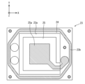
- FIG. 1 is a plan view showing an outline of the overall configuration of the piezoelectric vibration device 1.
- FIG. 2 is a bottom view showing an outline of the overall configuration of the piezoelectric vibration device 1.
- FIG. 3 is an exploded perspective view showing an outline of the overall configuration of the vibrator 2 in the piezoelectric vibrating device 1.
- FIG. 4 is a plan view of the vibrator 2.
- FIG. 5 is a cross-sectional view taken along the arrow A in FIG. 4.
- the piezoelectric vibration device 1 has a vibrator 2, an integrated circuit element 10, a substrate 11, and a mold portion 12 (see FIG. 6).
- the vibrator 2 is a piezoelectric element having a piezoelectric body that converts applied force into voltage or converts applied voltage into force.
- the vibrator 2 has a piezoelectric diaphragm 3 , a first sealing member 7 , a second sealing member 8 and a protective member 9 .
- the piezoelectric diaphragm 3 is a rectangular crystal vibrating piece cut out of crystal in a specific direction.
- the piezoelectric diaphragm 3 has a frame portion 4 , a vibrating portion 5 and a connecting portion 6 .
- the piezoelectric diaphragm 3 has a frame portion 4, a vibrating portion 5, and a connecting portion 6 integrally formed. That is, the frame portion 4, the vibrating portion 5, and the connecting portion 6 are configured as a single member.
- the frame portion 4 is a member that surrounds the vibrating portion 5 .
- the frame portion 4 is made of a rectangular plate material in plan view in a direction perpendicular to the pair of main surfaces having the largest area.
- the frame portion 4 is a frame-shaped member having a rectangular opening on each of the pair of main surfaces when viewed in the Z direction, which is a plan view. That is, the frame portion 4 has a rectangular penetrating portion 4c penetrating from one main surface toward the other main surface.
- the distance between the pair of main surfaces of the frame portion 4, which is the thickness of the frame portion 4, is the thickness t1.
- One main surface of the frame portion 4 has a first joint surface 4 a that is joined to the first sealing member 7 .
- the other main surface of the frame portion 4 has a second joint surface 4 b that joins with the second sealing member 8 .
- Both ends of the frame portion 4 in the longitudinal direction each have a vibrator mounting terminal 4d.
- the vibration part 5 is a piezoelectric body.
- the vibrating portion 5 is a substantially rectangular plate member in plan view in a direction perpendicular to the pair of principal surfaces having the largest area.
- the vibrating portion 5 is positioned within the frame of the frame portion 4 .
- the vibrating section 5 is positioned so that the pair of main surfaces face the opening of the frame section 4 when viewed in the Z direction, which is a plan view.
- the main surface of the vibrating portion 5 is positioned substantially parallel to the main surface of the frame portion 4 .
- the distance between the pair of main surfaces of the vibrating portion 5, which is the thickness of the vibrating portion 5, is a thickness t2 that is thinner than the thickness t1 of the frame portion 4. As shown in FIG.
- the vibrating portion 5 is positioned between the pair of main surfaces of the frame portion 4 within the frame of the frame portion 4 .
- a part of the vibrating section 5 is connected to the frame section 4 via a plate-like connecting section 6 .
- the vibrating portion 5 is held in a cantilevered state on the frame portion 4 via the connecting portion 6 . That is, the vibrating portion 5 is surrounded by the frame portion 4 with the penetrating portion 4c interposed therebetween.
- One main surface of the vibrating portion 5 has a first excitation electrode 5a.
- the other main surface of the vibrating portion 5 has a second excitation electrode 5b.
- the first excitation electrode 5a is connected to one vibrator mounting terminal 4d.
- the second excitation electrode 5b is connected to the other vibrator mounting terminal 4d.
- the first sealing member 7 and the second sealing member 8 that are sealing members are members that seal the inside of the frame portion 4 .
- the first sealing member 7 and the second sealing member 8 are resin films having a rectangular shape in plan view in a direction perpendicular to the pair of main surfaces having the largest area.
- the first sealing member 7 and the second sealing member 8 are, for example, polyimide resin films having heat resistance of about 300.degree.
- the first sealing member 7 and the second sealing member 8 have a thickness t3 of about 20 ⁇ m to 50 ⁇ m.
- the width X3 in the X direction, which is the longitudinal direction, of the first sealing member 7 and the second sealing member 8 is smaller than the width X1 in the X direction at the outer edge of the frame portion 4 when viewed in the Z direction, which is a plan view, It is larger than the width X2 in the X direction at the opening portion which is the inner edge of the frame portion 4 .
- the Y-direction width Y3 of the first sealing member 7 and the second sealing member 8, which is the transverse direction perpendicular to the X direction when viewed in the Z direction is larger than the Y-direction width Y1 of the outer edge of the frame portion 4. is also smaller than the width Y2 in the Y direction at the opening portion which is the inner edge of the frame portion 4 . That is, the first sealing member 7 and the second sealing member 8 are smaller than the frame portion 4 and larger than the opening of the frame portion 4 .
- the first sealing member 7 is joined to the first joining surface 4a provided on one main surface of the frame portion 4 with a joining material 13 that is a thermoplastic adhesive.
- the peripheral edge of the first sealing member 7 is located inside the outer edge of the frame portion 4 and outside the inner edge of the frame portion 4 .
- An end portion of the first sealing member 7 in the X direction is joined to a first joint surface 4 a located in the X direction on one main surface of the frame portion 4 .
- a Y-direction end portion of the first sealing member 7 is joined to a first joint surface 4 a located in the Y-direction on one main surface of the frame portion 4 .
- the portion of the first sealing member 7 that overlaps the first bonding surface 4 a when viewed in the Z direction is bonded to the frame portion 4 with the bonding material 13 .
- the first sealing member 7 covers the opening on one main surface of the frame 4 . Thereby, the first sealing member 7 closes the opening on one main surface of the frame portion 4 .
- the second sealing member 8 is joined by a joining material 13 to the second joining surface 4b of the other main surface of the frame portion 4. As shown in FIG. The peripheral edge of the second sealing member 8 is located inside the outer edge of the frame portion 4 and outside the inner edge of the frame portion 4 .
- the X-direction end portion of the second sealing member 8 is joined to a second joint surface 4 b located in the X-direction on the other main surface of the frame portion 4 .
- a Y-direction end of the second sealing member 8 is joined to a second joint surface 4 b located in the Y-direction on the other main surface of the frame portion 4 .
- the portion of the second sealing member 8 that overlaps the second bonding surface 4 b when viewed in the Z direction is bonded to the frame portion 4 with the bonding material 13 .
- the second sealing member 8 covers the opening on one main surface of the frame portion 4 . Thereby, the second sealing member 8 closes the opening portion of the other main surface of the frame portion 4 .
- the protective member 9 is a member that suppresses bending of at least the first sealing member 7 out of the first sealing member 7 or the second sealing member 8 due to the molding pressure of the resin forming the mold portion 12 .
- the protective member 9 is a plate-like member that is rectangular in plan view in a direction perpendicular to the pair of main surfaces having the largest area.
- the protective member 9 is made of silicon, which is a brittle material. It is desirable that the protective member 9 have such a rigidity that the maximum deflection is 20 ⁇ m or less in the case of being supported on both sides in the longitudinal direction when pressure generated during molding of the resin is applied.
- the longitudinal elastic modulus of the material and the Z A directional moment of inertia is defined.
- the protective member 9 is made of silicon. Moreover, in this embodiment, it is desirable that the protective member 9 have a thickness t4 of about 30 ⁇ m to 100 ⁇ m. A thickness t4 of the protection member 9 is thicker than a thickness t3 of the first sealing member 7 and the second sealing member 8 .
- the width X4 in the X direction which is the longitudinal direction of the protective member 9, is smaller than the width X1 in the X direction at the outer edge of the frame portion 4 of the piezoelectric diaphragm 3. is greater than the width X3 of Further, when viewed in the Z direction, the Y-direction width Y4 of the protective member 9 perpendicular to the X-direction is smaller than the Y-direction width Y1 of the outer edge of the frame portion 4, and the Y width of the first sealing member 7 greater than the direction width Y3. That is, the protective member 9 is smaller than the frame portion 4 and larger than the first sealing member 7 .
- the protective member 9 is bonded to the surface of the first sealing member 7 perpendicular to the Z direction with a thermoplastic adhesive or die attach agent as a bonding material 13 .
- the peripheral edge of the protective member 9 is positioned between the peripheral edge of the first sealing member 7 and the outer edge of the frame portion 4 . That is, the peripheral portion of the protective member 9 overlaps the first joint surface 4a of the frame portion 4 when viewed in the Z direction.
- the protective member 9 is supported by the frame portion 4 at its peripheral portion.
- the protective member 9 covers the opening portion of one main surface of the frame portion 4 with the first sealing member 7 interposed therebetween. In other words, the protective member 9 covers the entire first sealing member 7 including the portion overlapping the opening when viewed in the Z direction.
- the vibrator 2 configured as described above includes a piezoelectric diaphragm 3 , a first sealing member 7 that closes an opening of one principal surface of the piezoelectric diaphragm 3 , and the other principal surface of the piezoelectric diaphragm 3 . It is composed of a three-layer structure having a second sealing member 8 that closes the opening portion of the.
- the vibrator 2 has an internal space S defined by the frame portion 4 of the piezoelectric diaphragm 3 , the first sealing member 7 and the second sealing member 8 .
- the vibrator 2 has a vibrating portion 5 located within an internal space S. As shown in FIG.
- the internal space S is filled with an inert gas such as nitrogen gas.
- the vibrator 2 oscillates at a predetermined frequency by voltage applied from each vibrator mounting terminal 4d.
- an integrated circuit element 10 which is an electronic component element, is an IC that controls the vibrator 2.
- the integrated circuit element 10 has an electronic circuit such as an oscillation circuit that is connected to a temperature sensing element (thermistor) that detects the ambient temperature state and generates a predetermined oscillation output.
- the integrated circuit element 10 outputs the oscillation output generated by the oscillation circuit to the outside through the integrated circuit element mounting terminal 10a as a reference signal such as a clock signal.
- the integrated circuit element 10 is covered with resin except for the integrated circuit element mounting terminals 10a.
- the substrate 11 is an insulating substrate that electrically connects the vibrator 2 and the integrated circuit element 10 with a wiring pattern (not shown) and integrates them.
- the substrate 11 is made of a resin material.
- the substrate 11 is based on glass epoxy resin, which is an insulator, for example.
- One main surface of the substrate 11 is configured as a mounting surface 11a having a circuit formed of a conductor such as copper.
- the other main surface of the substrate 11 has substrate mounting terminals 11b for mounting on an external substrate.
- the circuit on the mounting surface 11a is electrically connected to the substrate mounting terminals 11b.
- the thickness of the substrate 11 is, for example, 0.17 mm.
- a vibrator 2 and an integrated circuit element 10 are mounted on the mounting surface 11a of the substrate 11, respectively. Both vibrator mounting terminals 4d of the vibrator 2 are electrically connected to circuits on the mounting surface 11a by conductive bonding materials 13, respectively.
- the vibrator 2 is arranged with the main surface covered with the first sealing member 7 and the second sealing member 8 directed in the Z direction. The vibrator 2 is positioned so that the second sealing member 8 faces the mounting surface 11a. The second sealing member 8 is in contact with the mounting surface 11a.
- the integrated circuit element mounting terminals 10a of the integrated circuit element 10 are electrically connected to circuits on the mounting surface 11a of the substrate 11 by wires 10b.
- the vibrator 2 and the integrated circuit element 10 are positioned side by side on the mounting surface 11 a of the substrate 11 .
- the vibrator 2 mounted on the substrate 11 is electrically connected to the external substrate from the vibrator mounting terminal 4d via a wiring pattern (not shown) of the substrate 11 and the substrate mounting terminal 11b. Further, the vibrating portion 5 of the vibrator 2 is held in a cantilevered state on the frame portion 4 of the piezoelectric diaphragm 3 by the connecting portion 6 . Thereby, the vibrating section 5 oscillates at a predetermined frequency by the voltage applied from the external substrate.
- the mold part 12 protects at least the oscillator 2 among the substrate 11 and the oscillator 2 and the integrated circuit element 10 mounted on the substrate 11 (see FIG. 6).
- the mold part 12 is a thermosetting resin such as an epoxy resin 12a.
- the molded portion 12 covers the substrate 11 and at least the oscillator 2 among the oscillator 2 and the integrated circuit element 10 mounted on the substrate 11 with a thermoset epoxy resin 12a.
- the mold part 12 covers the substrate 11 and the vibrator 2 and the integrated circuit element 10 mounted on the substrate 11 .
- FIG. 6 is a cross-sectional view taken along the arrow A in FIG. 4 in a state where the piezoelectric vibration device 1 is resin-molded in the mold W.
- the mold part 12 is molded by a transfer method in which the cavity of the mold W is filled with molten resin.
- the cavity is filled with molten epoxy resin 12a by a plunger (not shown).
- the epoxy resin 12a is filled into the cavity with a predetermined filling pressure by a plunger.
- the epoxy resin 12a is pressurized with a predetermined molding pressure for a predetermined time.
- the epoxy resin 12a is thermally cured while being held at a predetermined molding pressure.
- the thermoset epoxy resin 12 a covers the vibrator 2 and the substrate 11 as the mold portion 12 .
- the vibrator 2 and the substrate 11 located in the cavity filled with the epoxy resin 12a are in contact with the frame portion 4 of the piezoelectric diaphragm 3, the protective member 9 and the substrate 11 with the epoxy resin 12a.
- the main surface of the first sealing member 7 is covered with the main surface of the protective member 9 when viewed in the Z direction.
- the first sealing member 7 and the protection member 9 are joined by a joining material 13 .
- the protective member 9 is in close contact with the first sealing member 7 . Therefore, the principal surface of the first sealing member 7 is not in contact with the epoxy resin 12a.
- the second sealing member 8 is covered with the substrate 11 when viewed in the Z direction. Therefore, the main surface of the second sealing member 8 is not in contact with the epoxy resin 12a.
- the connecting portion 6 and the vibrating portion 5 of the piezoelectric diaphragm 3 are sealed in the internal space S by the first sealing member 7 and the second sealing member 8, they are not in contact with the epoxy resin 12a.
- the epoxy resin 12a While the epoxy resin 12a is held by the molding pressure, the epoxy resin 12a is applied to the frame portion 4 of the piezoelectric diaphragm 3, the protective member 9 and the substrate 11, which are in contact with the epoxy resin 12a in the vibrator 2 and the substrate 11. Forming pressure is applied from a direction perpendicular to the contact surface. A holding pressure is applied in the Z direction to the main surface of the protective member 9 perpendicular to the Z direction (see arrow).
- the secondary moment of area of the protective member 9 in the Z direction which is the direction perpendicular to the main surface of the vibrator 2 , is larger than the secondary moment of area of the first sealing member 7 in the Z direction.
- the protective member 9 is made of a brittle material having a greater modulus of longitudinal elasticity than that of a resin-based material. Therefore, the protective member 9 has higher rigidity than the first sealing member 7 due to its shape and material.
- Such a protective member 9 is bent by about 20 ⁇ m toward the piezoelectric diaphragm 3 in the Z direction due to a predetermined molding pressure.
- the first sealing member 7 joined to the protective member 9 is bent by about 20 ⁇ m toward the piezoelectric diaphragm 3 in the Z direction along the bending of the protective member 9 in the Z direction.
- the first sealing member 7 before bending is separated from the vibrating portion 5 of the piezoelectric diaphragm 3 by more than 20 ⁇ m in the Z direction. Therefore, the first sealing member 7 does not come into contact with the vibrating portion 5 even if it bends toward the piezoelectric diaphragm 3 in the Z direction due to the molding pressure.
- the peripheral edge of the protective member 9 is located outside the peripheral edge of the first sealing member 7 and inside the outer peripheral edge of the frame portion 4 . That is, a gap G equal to the thickness t3 of the first sealing member 7 and the thickness of the bonding material 13 is formed between the peripheral edge portion of the protective member 9 outside the first sealing member 7 and the bonding surface of the frame portion 4 . is occurring.
- Epoxy resin 12a enters the gap G. Therefore, the first sealing member 7 is in contact with the end face perpendicular to the X direction and the end face perpendicular to the Y direction with the epoxy resin 12a. The movement of the first sealing member 7 in the X direction and the Y direction is restricted by thermosetting the epoxy resin 12a.
- the piezoelectric vibrating plate 3 supporting the vibrating portion 5 thinner than the frame portion 4 within the frame of the frame portion 4 is a first sealing made of a resin film. It has a three-layer structure vibrator 2 covered with a member 7 and a second sealing member 8 .
- a protective member 9 covers the first sealing member 7 that closes the main surface including the opening of the frame 4 . Therefore, the epoxy resin 12a forming the mold portion 12 does not contact the main surface of the first sealing member 7 perpendicular to the Z direction.
- the protective member 9 covers the first sealing member 7 with its peripheral edge supported by the frame portion 4 . That is, the molding pressure of the epoxy resin 12 a applied to the protective member 9 is received by the frame portion 4 .
- the molding pressure applied to the first sealing member 7 is reduced according to the ratio of the area of the protective member 9 to the area of the first sealing member 7 covering the opening of the frame portion 4 .
- the protective member 9 covers the entire portion of the first sealing member 7 that covers the opening of the frame portion 4 . Therefore, the vibrator 2 receives all the molding pressure of the epoxy resin 12 a applied to the first sealing member 7 by the protective member 9 . As a result, at least the first sealing member 7 out of the first sealing member 7 and the second sealing member 8 can be restrained from bending during molding with the epoxy resin 12a.
- the thickness of the piezoelectric vibration device 1 is the sum of the thickness of the vibrator 2, the thickness of the substrate 11, and the thickness of the molding resin (epoxy resin 12a).
- the resistance of the first sealing member 7 to the molding pressure from the mold resin is improved because it is covered with the protective member 9 . Therefore, the piezoelectric vibration device 1 can suppress bending of the first sealing member 7 during molding with the epoxy resin 12a.
- the thickness of the piezoelectric vibration device 1 is increased by forming a three-layer structure in which the frame portion 4 having the vibrating portion 5 inside the frame is covered with the first sealing member 7 and the second sealing member 8 which are resin films. can be suppressed.
- the vibrator 2 of the piezoelectric vibrating device 1 has a gap G between the frame portion 4 and the protective member 9 due to the first sealing member 7 .
- the epoxy resin 12a enters the gap G due to molding pressure. Therefore, deformation of the first sealing member 7 located between the frame portion 4 and the protective member 9 is suppressed by the thermoset epoxy resin 12a.
- the protective member 9 is larger than the first sealing member 7, it can cover at least a part of the first sealing member 7 even if the position in the X direction and the Y direction with respect to the first sealing member 7 is slightly deviated. can be done. As a result, at least the first sealing member 7 out of the first sealing member 7 and the second sealing member 8 can be restrained from bending during molding with the epoxy resin 12a.
- the substrate 11 of the piezoelectric vibration device 1 is made of a glass epoxy resin material that can be easily processed such as cutting. Thereby, the piezoelectric vibration device 1 having an arbitrary shape can be easily constructed.
- the vibrator 2 has the penetrating portion 4c between the frame portion 4 and the vibrating portion 5, and supports the vibrating portion 5 in a cantilever manner.
- the vibrator 2 may be configured without the penetrating portion 4c between the frame portion 4 and the vibrating portion 5.
- FIG. 7 is a cross-sectional view taken along the arrow A in FIG. 4 in a modification of the piezoelectric vibration device 1. As shown in FIG.
- the vibrator 14 without the penetrating portion 4c has a piezoelectric diaphragm 15, a first sealing member 7, a second sealing member 8, and a protective member 9.
- the piezoelectric diaphragm 15 has a frame portion 16 and a vibrating portion 17 integrally formed. That is, the frame portion 16 and the vibrating portion 17 are configured as a single member.
- specific descriptions of the same points as those of the already described embodiments will be omitted, and different parts will be mainly described.
- the frame portion 16 is a member that surrounds the vibrating portion 17 .
- the frame portion 16 is made of a rectangular plate material in plan view in a direction perpendicular to the pair of main surfaces having the largest area.
- the frame portion 16 is a frame-shaped member having a pair of main surfaces each having a rectangular opening when viewed in the Z direction, which is a plan view.
- the frame portion 16 has a first joint surface 16 a that joins with the first sealing member 7 and a second joint surface 16 b that joins with the second sealing member 8 . Both ends of the frame portion 16 in the longitudinal direction each have a transducer mounting terminal 16d.
- the frame portion 16 has a rectangular concave portion 16e on one main surface and a rectangular concave portion 16f on the other main surface when viewed in the Z direction. Further, the recessed portion 16e on one of the main surfaces and the recessed portion 16f on the other main surface are not communicated with each other. That is, the frame portion 16 does not have a through portion.
- the vibration part 17 is a piezoelectric body.
- the vibrating portion 17 is a substantially rectangular plate member in plan view in a direction perpendicular to the pair of principal surfaces having the largest area.
- One main surface of the vibrating portion 17 is the bottom surface of one recess 16 e in the frame portion 16 .
- the other main surface of the vibrating portion 17 is the bottom surface of the other recessed portion 16 f of the frame portion 16 .
- the vibrating portion 17 is positioned such that the pair of main surfaces face the opening portion of the frame portion 16 when viewed in the Z direction, which is a plan view.
- the main surface of the vibrating portion 17 is positioned substantially parallel to the main surface of the frame portion 16 .
- the vibrating portion 17 is positioned between the pair of main surfaces of the frame portion 16 within the frame of the frame portion 16 .
- the vibrating portion 17 is connected to the frame portion 16 at its periphery. That is, the vibrating portion 17 is supported by the frame portion 16 along the entire periphery.
- One main surface of the vibrating portion 17 has a first excitation electrode 17a.
- the other principal surface of the vibrating portion 17 has a second excitation electrode 17b.
- the vibrator 14 of the piezoelectric vibrating device 1 has the concave portion 16e on one main surface of the frame portion 16 and the concave portion 16f on the other main surface.
- the bottom surfaces of the recess 16e and the recess 16f constitute a vibrating portion 17.
- the vibrator 14 has a three-layer structure in which the first sealing member 7 covers the opening of the recess 16e of the frame 16 and the second sealing member 8 covers the opening of the recess 16f. Since the first sealing member 7 is covered with the protective member 9, the resistance to molding pressure from the epoxy resin 12a is improved. Therefore, the first sealing member 7 can suppress bending of the first sealing member 7 during molding with the epoxy resin 12a.
- FIG. 8 is a plan view schematically showing the overall configuration of a piezoelectric vibration device 21 according to Embodiment 2 of the present invention.
- FIG. 9 is a side view of the vibrator 22 in the piezoelectric vibration device 21.
- FIG. 10 is a cross-sectional view taken along line D in FIG. 9.
- FIG. 11 is a bottom view of the vibrator 22.
- FIG. 12 is a plan view showing the size of the integrated circuit element 28 with respect to the vibrator 22. As shown in FIG. FIG.
- FIG. 13 is a side view of the piezoelectric vibration device 21.
- FIG. FIG. 14 is a side view of a modification of the piezoelectric vibration device 21.
- FIG. 13 is a side view of the piezoelectric vibration device 21.
- FIG. 14 is a side view of a modification of the piezoelectric vibration device 21.
- FIG. 13 is a side view of the piezoelectric vibration device 21.
- FIG. 14 is a side view of a modification of the piezoelectric vibration device 21.
- the piezoelectric vibration device 21 has a vibrator 22, an integrated circuit element 28, a substrate 29, and a mold portion (not shown).
- the vibrator 22 is a piezoelectric vibrator having a piezoelectric vibrating plate 23, a first sealing member 26, and a second sealing member 27.
- the vibrator 22 is a three-layer laminate having a sandwich structure in which a piezoelectric diaphragm 23 is sandwiched between a first sealing member 26 and a second sealing member 27 .
- the piezoelectric vibration plate 23 is a rectangular plate-shaped member made of crystal, which is a piezoelectric material.
- the piezoelectric diaphragm 23 has a frame portion 24 and a vibrating portion 25 .
- the piezoelectric diaphragm 23 has a frame portion 24 and a vibrating portion 25 integrally formed. That is, the frame portion 24 and the vibrating portion 25 are configured as a single member.
- the frame portion 24 is a member that surrounds the vibrating portion 25 .
- the frame portion 24 is formed on the outer edge portions of the pair of main surfaces having the largest area in the piezoelectric diaphragm 23 .
- a portion surrounded by the frame portion 24 is recessed from the main surface of the piezoelectric diaphragm 23 . That is, the frame portion 24 is a frame-shaped portion having rectangular openings when viewed in the Z direction perpendicular to the main surface.
- a pair of excitation electrodes 25a are positioned in the portions of one principal surface and the other principal surface of the piezoelectric diaphragm 23 surrounded by the frame portion 24 .
- the pair of excitation electrodes 25 a are positioned so as to face each other in the thickness direction of the piezoelectric diaphragm 23 .
- the piezoelectric diaphragm 23, when viewed in the Z direction that is the direction perpendicular to the pair of principal surfaces having the largest area, is arranged from one principal surface so as to surround the pair of excitation electrodes 25a in the portion surrounded by the frame portion 24. It has a through portion 23a penetrating toward the other main surface.
- the penetrating portion 23a penetrates so as to surround the pair of excitation electrodes 25a with one portion left.
- the portion where the pair of excitation electrodes 25a are located is configured as a plate-like member having a cantilever structure. That is, the portion where the pair of excitation electrodes 25a are located is configured as the vibrating portion 25 capable of vibrating in the Z direction.
- the vibration part 25 is a piezoelectric body.
- the vibrating portion 25 is a substantially rectangular plate-like portion in plan view in a direction perpendicular to the pair of principal surfaces having the largest area.
- the vibrating portion 25 is positioned within the frame of the frame portion 24 .
- the vibrating portion 25 is positioned so that the pair of main surfaces face the opening portion of the frame portion 24 when viewed in the Z direction.
- the main surface of the vibrating portion 25 is positioned substantially parallel to the main surface of the frame portion 24 .
- the thickness of the vibrating portion 25 is thinner than the thickness of the frame portion 24 .
- the vibrating portion 25 is positioned between the pair of main surfaces of the frame portion 24 within the frame of the frame portion 24 .
- One main surface of the frame portion 24 has a bonding material 23 b that is bonded to the first sealing member 26 so as to surround the vibrating portion 25 .
- the other main surface of the frame portion 24 has a bonding material 23 b that is bonded to the second sealing member 27 so as to surround the vibrating portion 25 .
- Each bonding material 23b is configured in an annular shape.
- the bonding material 23b is a PVD film made of the same metal as the metal forming the pair of excitation electrodes 25a.
- the first sealing member 26 is a member that seals the vibrating portion 25 of the piezoelectric diaphragm 23 .
- the first sealing member 26 is a rectangular plate member made of the same crystal as the piezoelectric diaphragm 23 .
- the first sealing member 26 has substantially the same shape as the piezoelectric diaphragm 23 . That is, the first sealing member 26 has a shape capable of covering the entire one main surface of the piezoelectric diaphragm 23 when the one main surface is opposed to the one main surface of the piezoelectric diaphragm 23 . That is, the first sealing member 26 has a shape that can cover the entire opening of the frame portion 24 .
- the first sealing member 26 has a bonding material that bonds to the bonding material 23 b of the piezoelectric diaphragm 23 on one main surface.
- the bonding material of the first sealing member 26 is a PVD film made of the same metal as the bonding material 23 b of the piezoelectric diaphragm 23 .
- the first sealing member 26 has external mounting terminals 26a electrically connected to the integrated circuit element mounting terminals 28a of the integrated circuit element 28 on the other main surface.
- the external mounting terminal 26a is a plate-like terminal made of a conductive metal.
- the second sealing member 27 is a member that seals the vibrating portion 25 of the piezoelectric diaphragm 23 .
- the second sealing member 27 is a rectangular plate member made of the same crystal as the piezoelectric diaphragm 23 .
- the second sealing member 27 has substantially the same shape as the piezoelectric diaphragm 23 . That is, the second sealing member 27 has a shape that can cover the entire other main surface of the piezoelectric diaphragm 23 when one main surface faces the other main surface of the piezoelectric diaphragm 23 . That is, the second sealing member 27 has a shape that can cover the entire opening of the frame portion 24 .
- the second sealing member 27 has a bonding material that bonds to the bonding material 23 b of the piezoelectric diaphragm 23 on one main surface.
- the bonding material of the second sealing member 27 is a PVD film made of the same metal as the bonding material 23 b of the piezoelectric diaphragm 23 .
- the second sealing member 27 has four vibrator mounting terminals 27a electrically connected to the electrodes of the substrate 29 on the other main surface.
- the four transducer mounting terminals 27a are plate-like terminals made of conductive metal.
- the four transducer mounting terminals 27a are configured in a substantially L shape when viewed in the Z direction.
- the first sealing member 26 is positioned on one main surface of the piezoelectric diaphragm 23 .
- One main surface of the piezoelectric diaphragm 23 is covered with a first sealing member 26 .
- the bonding material 23b on one main surface of the piezoelectric diaphragm 23 and the bonding material of the first sealing member 26 are diffusion-bonded.
- the excitation electrode 24 a on one main surface side of the piezoelectric diaphragm 23 is hermetically sealed by the first sealing member 26 .
- a second sealing member 27 is located on the other main surface of the piezoelectric diaphragm 23 .
- the other main surface of piezoelectric diaphragm 23 is covered with second sealing member 27 .
- the bonding material 23b on the other main surface of the piezoelectric diaphragm 23 and the bonding material of the second sealing member 27 are diffusion-bonded.
- the excitation electrode 24 a on the other main surface side of the piezoelectric diaphragm 23 is hermetically sealed by the second sealing member 27 .
- the vibrator 22 configured in this manner is configured as a sandwich structure package in which both main surfaces of the piezoelectric diaphragm 23 are sealed with the first sealing member 26 and the second sealing member 27, respectively.
- the vibrator 22 has an internal structure including the vibrating portion 25 of the piezoelectric vibration plate 23. A space is formed. That is, the vibrator 22 has a vibrating portion 25 including a pair of excitation electrodes 25a hermetically sealed in the inner space of the package.
- the integrated circuit element 28 is an IC that controls the vibrator 2. Since the configuration of the integrated circuit element 28 is the same as that of the integrated circuit element 10 of the first embodiment, description thereof is omitted.
- the integrated circuit element 28 is covered with resin except for the integrated circuit element mounting terminals 28a.
- An integrated circuit element 28 is mounted on the other main surface of the first sealing member 26 . Integrated circuit element mounting terminals 28a of the integrated circuit element 28 are electrically connected to external mounting terminals 26a of the first sealing member 26 by soldering or the like.
- the integrated circuit element 28 is a plate-like member that is rectangular in plan view in a direction perpendicular to the pair of main surfaces having the largest area.
- the integrated circuit element 28 desirably has such a rigidity that the maximum deflection is 5 .mu.m or less when supported on both ends in the longitudinal direction when pressure generated during molding of the resin is applied. Therefore, the integrated circuit element 28 has a longitudinal elastic modulus of a material such that at least the first sealing member 26 or the second sealing member 27 has a higher stiffness than the first sealing member 26, and the direction of plan view. A moment of inertia in the Z direction is defined.
- the integrated circuit element 28 preferably has a thickness of 80 ⁇ m or more. The thickness of the integrated circuit element 28 is thicker than the thicknesses of the first sealing member 26 and the second sealing member 27 .
- the width X13 in the X direction which is the longitudinal direction of the integrated circuit element 28, is smaller than the width X11 in the X direction at the outer edge of the frame portion 24. It is larger than the width X12 in the X direction.
- the Y-direction width Y13 of the integrated circuit element 28 perpendicular to the X direction is smaller than the Y-direction width Y11 at the outer edge of the frame 24, and the Y It is larger than the width Y12 of the direction. That is, the integrated circuit element 28 is smaller than the frame 24 and larger than the opening of the frame 24 . Therefore, the outer edge portion of the integrated circuit element 28 is supported by the frame portion 24 of the piezoelectric diaphragm 23 via the first sealing member 26 .
- the substrate 29 is an insulating substrate that electrically connects the vibrator 22 and the integrated circuit element 28 with a wiring pattern (not shown) and integrates them.
- One main surface of the substrate 29 has connection terminals 29b for mounting the vibrator 22 thereon.
- the other main surface of the substrate 29 has substrate mounting terminals 29c for mounting on an external substrate (see FIG. 13).
- the connection terminal 29b is electrically connected to the substrate mounting terminal 29c.
- Other configurations of the substrate 29 are substantially the same as those of the substrate 11 of the first embodiment, so description thereof will be omitted.
- a vibrator 22 on which an integrated circuit element 28 is mounted is mounted on the mounting surface 29a.
- the vibrator 22 is arranged on the substrate 29 with the second sealing member 27 facing the mounting surface 29a.
- the vibrator mounting terminals 27a of the second sealing member 27 are electrically connected to connection terminals 29b of the mounting surface 29a by conductive solder or the like.
- the integrated circuit element mounting terminals 28a of the integrated circuit element 28 are electrically connected to circuits on the mounting surface 29a of the substrate 29 by wires 28b.
- the vibrator 22 and the integrated circuit element 28, which are electronic component elements, mounted on the substrate 29 are electrically connected to an external substrate from the vibrator mounting terminals 27a through wiring patterns (not shown) of the substrate 29 and substrate mounting terminals 29c. It is also, the vibrating portion 25 of the vibrator 22 oscillates at a predetermined frequency due to the voltage applied from the external substrate.
- the molded portion (not shown) protects the substrate 29 and at least the oscillator 22 among the oscillator 22 and the integrated circuit element 28 mounted on the substrate 29 with epoxy resin. Since the molded portion is the same as the molded portion 12 in the first embodiment, the explanation is omitted.
- the vibrator 22 and the substrate 29 are molded with an epoxy resin (not shown)
- the vibrator 22 and the integrated circuit element 28 may have contact surfaces of the epoxy resin during the injection of the epoxy resin.
- Forming pressure is applied from the vertical Z-direction (see arrow).
- a portion of the first sealing member 26 that covers the opening of the piezoelectric diaphragm 23 is covered with an integrated circuit element 28 . Therefore, the molding pressure applied to the portion of the first sealing member 26 covering the opening portion of the piezoelectric diaphragm 23 as viewed in the Z direction is applied to the integrated circuit element 28 .
- the integrated circuit element 28 has a double-end structure in which the outer edge portion is supported by the frame portion 24 .
- the deflection amount of the first sealing member 26 covering the opening of the piezoelectric diaphragm 23 is suppressed by being covered with the integrated circuit element 28 . Therefore, the first sealing member 26 does not come into contact with the vibrating portion 25 even if it bends in the Z direction due to the molding pressure. In this manner, the integrated circuit element 28 functions as a protective member that covers the first sealing member 26 so that molding pressure is not applied to the first sealing member 26 .
- the piezoelectric vibrating plate 23 supporting the vibrating portion 25 thinner than the frame portion 24 within the frame of the frame portion 24 is a first sealing member made of crystal.
- a vibrator 22 having a three-layer structure covered with 26 and a second sealing member 27 and an integrated circuit element 28 are mounted on a mounting surface 29 a of a substrate 29 .
- At least the vibrator 22 of the piezoelectric vibration device 21 is covered with an epoxy resin.
- the vibrator 22 has a first sealing member 26 that closes the opening of the frame portion 24 of the piezoelectric diaphragm 23 and is covered with an integrated circuit element 28 .
- the epoxy resin forming the mold portion does not contact the main surface of the portion of the first sealing member 26 that covers the opening of the piezoelectric diaphragm 23 and is perpendicular to the Z direction.
- the integrated circuit element 28 covers the first sealing member 26 with its peripheral edge supported by the frame portion 24 .
- the molding pressure of the epoxy resin applied to the integrated circuit element 28 is received by the frame portion 24 .
- an integrated circuit element 28 is mounted as a protective member on the main surface of the first sealing member 26 of the vibrator 22 (see FIG. 13).
- the vibrator 22 may have the integrated circuit element 28 mounted on the protective member 9 joined to the first sealing member 26 . That is, the first sealing member 26 is protected by the protective member 9 from the molding pressure of the mold portion (not shown). Therefore, the piezoelectric vibration device 21 can mount the integrated circuit element 28 of any size on the vibrator 22 .
- the protective member 9 may have electrical connection means such as wiring patterns and through holes, and may be configured to be electrically connected to the vibrator 22 .
- FIG. 15 is a plan view showing an outline of the overall configuration of the piezoelectric vibration device 41.
- FIG. 16 is a side view showing an outline of the overall configuration of the piezoelectric vibration device 41. As shown in FIG.
- the piezoelectric vibration device 41 has a vibrator 42, an integrated circuit element 51, a substrate 52, and a mold portion (not shown).
- the vibrator 42 has a holding member 43 , a piezoelectric element 48 , a sealing member 49 and a protective member 50 .
- the holding member 43 is a box-shaped container made of an insulating material for holding the piezoelectric element 48 .
- the holding member 43 is a ceramic housing in this embodiment.
- the holding member 43 is formed by sintering ceramic powder. Note that the holding member 43 may be configured by stacking a plurality of insulators.
- the holding member 43 has a bottom portion 44 , electrode pads 45 , a frame portion 46 and external terminals 47 .
- the bottom portion 44 is a portion that constitutes the bottom surface of the holding member 43 .
- the bottom portion 44 is composed of a rectangular plate member.
- An electrode pad 45 made of a conductive metal is formed along one short side of a rectangular plate-like member on the upper surface, which is one surface of the bottom portion 44 .
- the electrode pad 45 is electrically connected with the piezoelectric element 48 .
- the electrode pad 45 is part of an electric circuit that applies voltage to the piezoelectric element 48 .
- An external terminal 47 made of a conductive metal is vapor-deposited on the lower surface, which is the other surface of the bottom portion 44 .
- the external terminals 47 are electrically connected to the substrate 52 .
- the external terminal 47 is a terminal for transmitting a signal from the substrate 52 to the piezoelectric element 48 and applying a voltage.
- the electrode pads 45 and the external terminals 47 are electrically connected by wiring patterns (not shown).
- the frame part 46 is a part that constitutes the side surface of the holding member 43 .
- the frame portion 46 is positioned on the outer edge of the bottom portion 44 .
- the frame portion 46 is a frame-shaped wall surrounding the bottom portion 44 .
- the frame portion 46 extends upward from the upper surface of the bottom portion 44 .
- the frame portion 46 has a predetermined thickness from the outer surface toward the inner surface.
- the upper end portion of the frame portion 46 has a joint surface 46 a that is joined to the sealing member 49 .
- the upper surface of the bottom portion 44 and the inner surface of the frame portion 46 form an internal space for accommodating the piezoelectric element 48 .
- the holding member 43 opens upward from the upper surface of the bottom portion 44 .
- the electrode pads 45 are located within the internal space.
- the piezoelectric element 48 which is the vibrating part, is a piezoelectric body that converts applied force into voltage or converts applied voltage into force.
- the piezoelectric element 48 is a rectangular crystal vibrating piece (for example, an AT-cut crystal piece) obtained by cutting crystal in a specific direction. Electrodes (not shown) are vapor-deposited on both of the pair of main surfaces having the largest area of the piezoelectric element 48 .
- the piezoelectric element 48 is positioned within the internal space of the holding member 43 .
- the electrodes of the piezoelectric element 48 are adhered to the electrode pads 45 of the holding member 43 .
- the piezoelectric element 48 can be electrically connected to the substrate 52 from the electrode via the electrode pad 45 , the wiring pattern (not shown), and the external terminal 47 . Also, the piezoelectric element 48 is held in a cantilevered state by the holding member 43 . Thereby, the piezoelectric element 48 oscillates at a predetermined frequency by the voltage applied from the external substrate.
- the sealing member 49 is a lid member that seals the internal space of the holding member 43 .
- the sealing member 49 is made of, for example, a metal material such as Kovar. Further, the sealing member 49 is subjected to, for example, electrolytic nickel plating or electroless nickel plating.
- the sealing member 49 is positioned at the upper end portion of the holding member 43 with one of its lower surfaces facing the holding member 43 .
- the sealing member 49 has a size that covers the opening portion of the holding member 43 when viewed in the Z direction, which is a plan view. Also, the sealing member 49 is smaller than the holding member 43 when viewed in the Z direction.
- the sealing member 49 is provided with a frame-shaped sealing member at a portion overlapping the joint surface 46a of the frame portion 46 of the holding member 43 when viewed in the Z direction.
- the sealing member 49 is joined to the joint surface 46 a of the frame portion 46 .
- the piezoelectric element 48 is hermetically sealed within the internal space of the holding member 43 by the sealing member 49 .
- the protective member 50 is a member that suppresses the bending of the sealing member 49 due to the molding pressure of the resin that constitutes the mold portion (not shown). Since the configuration of the protection member 50 is the same as that of the protection member 9 of the first embodiment, description thereof is omitted.
- the protection member 50 is configured to have approximately the same size as the holding member 43 when viewed in the Z direction.
- the protective member 50 is bonded to the surface of the sealing member 49 perpendicular to the Z direction with a thermoplastic adhesive or die attach agent, which is a bonding material.
- the protective member 50 covers the entire sealing member 49 including the portion overlapping the opening when viewed in the Z direction.
- the integrated circuit element 51 is an IC that controls the vibrator 42 . Since the configuration of the integrated circuit element 51 is the same as that of the integrated circuit element 10 of the first embodiment, description thereof is omitted.
- the integrated circuit element 51 outputs the oscillation output generated by the oscillation circuit to the outside through the integrated circuit element mounting terminal 51a as a reference signal such as a clock signal.
- the substrate 52 is an insulating substrate that electrically connects the vibrator 42 and the integrated circuit element 51 with a wiring pattern (not shown) and integrates them.
- One main surface of the substrate 52 is configured as a mounting surface 52a having connection terminals 52b for mounting the vibrator 42 thereon.
- the integrated circuit element mounting terminals 51a of the integrated circuit element 51 are electrically connected to circuits on the mounting surface 29a of the substrate 52 by wires 51b.
- the other main surface of the substrate 52 has substrate mounting terminals 52c for mounting on an external substrate.
- Other configurations of the substrate 52 are substantially the same as those of the substrate 11 of the first embodiment, so description thereof will be omitted.
- the molded portion (not shown) protects the substrate 52 and at least the oscillator 42 among the oscillator 42 and the integrated circuit element 51 mounted on the substrate 52 with epoxy resin. Since the molded portion is the same as the molded portion 12 in the first embodiment, the explanation is omitted.
- the molding pressure applied to the vibrator 42 is applied to the protective member 50 covering the sealing member 49 of the vibrator 42 . Therefore, the amount of deflection of the sealing member 49 covering the opening of the holding member 43 is suppressed by being covered with the protective member 50 . Therefore, the sealing member 49 does not come into contact with the piezoelectric element 48 even if it bends in the Z direction due to the molding pressure.
- the resin films that constitute the first sealing member 7 and the second sealing member 8 are polyimide resin films.
- the first sealing member and the second sealing member are not limited to polyimide resin films, and resins classified as super engineering plastics, such as polyamide resin and polyetheretherketone resin films, are used. may
- the protective member 9 is made of silicon.
- the protective member may be made of a brittle material such as glass, crystal, quartz, ceramic, or the like, or a ductile material such as alumina.
- the protective members 9 and 50 and the integrated circuit element 28 may cover a part or all of the sealing member.
- the peripheral edge of the protective member 9 is located inward of the outer peripheral edge of the frame portion 4 of the piezoelectric diaphragm 3 .
- the peripheral edge of the protective member may be located outside the outer peripheral edge of the frame portion of the piezoelectric diaphragm.
- the peripheral edge of the first sealing member 7 is located inward of the outer peripheral edge of the piezoelectric diaphragm 3 and the peripheral edge of the protective member 9 .
- the first protective member may be located outside the outer peripheral edge of the piezoelectric diaphragm and the peripheral edge of the protective member.
- the substrates 11 and 29 in the above-described embodiments are made of glass polyimide resin.
- the substrate may be a glass composite substrate such as a glass epoxy resin substrate, a fluororesin substrate, a ceramic substrate, or the like.
- the piezoelectric vibration devices 1 and 21 are vibrators having a three-layer structure in which the piezoelectric vibration plates 3 and 23, the first sealing members 7 and 26, and the second sealing members 8 and 27 are laminated. 2, 22.
- the piezoelectric vibration device may have a vibrator with a three-layer structure or more.
- the vibrator may be a four-layer vibrator in which a sensor such as a thermistor is further mounted on the main surface of the first sealing member.
- the vibrator 42 has a piezoelectric element 48 that is a vibrating portion and is composed of a rectangular crystal vibrating piece (for example, an AT-cut crystal piece).
- the vibrator is not limited to the AT-cut crystal plate, and a crystal plate with a cutting angle other than the AT-cut such as a tuning-fork type crystal plate having a vibrating portion, an SC-cut crystal plate, or the like may be used.
- the piezoelectric vibration device 1 has the vibration portions 5 and 17 positioned within the internal space S of the piezoelectric vibration plate 3 .
- the piezoelectric vibration device may be a so-called H-structured piezoelectric vibration device having a bottom and frame-shaped side walls extending in directions perpendicular to the two planes facing each other on the bottom.
- a piezoelectric element is positioned on one plane of the bottom portion and inside one of the side wall portions.
- an electronic component element is mounted on the other plane of the bottom portion and inside the other side wall portion.
- a first sealing member is joined to the tip of the one side wall, and a second sealing member is joined to the tip of the other side wall.
- the thickness of the vibrating portion 25 positioned within the frame portion 24 is thinner than the thickness of the frame portion 24 .
- the vibrating portion may have the same thickness as the frame portion.
- the first sealing member and the second sealing member that are joined to the frame have recesses on their main surfaces facing the vibrating section. Thereby, the vibrator has a gap between the first sealing member and the second sealing member and the vibrating portion.
- the integrated circuit element 28 is joined onto the first sealing member 26 by soldering.
- the integrated circuit element may be bonded to the first sealing member by a die attach tape, a conductive adhesive, or the like.
- integrated circuit elements 10, 28, 51 having oscillator circuit elements which are electronic component elements for controlling oscillators, are mounted on substrates 11, 29, 52.
- FIG. An integrated circuit element 28, which is an electronic component element is mounted on the vibrator 22 as a protective member.
- the electronic component elements mounted on the substrate and vibrator may be electronic components such as oscillation circuit element thermistors and various sensors.
Landscapes
- Physics & Mathematics (AREA)
- Engineering & Computer Science (AREA)
- Microelectronics & Electronic Packaging (AREA)
- Acoustics & Sound (AREA)
- Condensed Matter Physics & Semiconductors (AREA)
- General Physics & Mathematics (AREA)
- Computer Hardware Design (AREA)
- Power Engineering (AREA)
- Piezo-Electric Or Mechanical Vibrators, Or Delay Or Filter Circuits (AREA)
- Oscillators With Electromechanical Resonators (AREA)
Abstract
Description
<圧電振動デバイス1の構成>
図1から図5を用いて、本発明の実施形態1である圧電振動デバイス1について説明する。図1は、圧電振動デバイス1の全体構成の概略を示す平面図である。図2は、圧電振動デバイス1の全体構成の概略を示す底面図である。図3は、圧電振動デバイス1における振動子2の全体構成の概略を示す分解斜視図である。図4は、振動子2の平面図である。図5は、図4におけるA矢視断面図である。 [Embodiment 1]
<Configuration of
A
なお、上述の実施形態1において、振動子2は、枠部4と振動部5との間に貫通部4cを有し、振動部5を片持ち支持している。しかしながら、図7に示すように、振動子2は、枠部4と振動部5との間に貫通部4cを有さない構成でもよい。図7は、圧電振動デバイス1の変形例での図4におけるA矢視断面図である。 [Modification of Embodiment 1]
In the first embodiment described above, the
<圧電振動デバイス21の構成>
次に、図8から図13を用いて、本発明の実施形態2である圧電振動デバイス21について説明する。図8は、本発明の実施形態2に係る圧電振動デバイス21の全体構成の概略を示す平面図である。図9は、圧電振動デバイス21における振動子22の側面図である。図10は、図9におけるD矢視断面図である。図11は、振動子22の底面図である。図12は、振動子22に対する集積回路素子28の大きさを示す平面図である。図13は、圧電振動デバイス21の側面図である。図14は、圧電振動デバイス21の変形例における側面図である。なお、以下の実施形態において、既に説明した実施形態と同様の点に関してはその具体的説明を省略し、相違する部分を中心に説明する。 [Embodiment 2]
<Configuration of
Next, a
また、上述の実施形態2において、振動子22の第1封止部材26上には、主面に保護部材として集積回路素子28が搭載されている(図13参照)。しかしながら、図14に示すように、振動子22は、第1封止部材26に接合された保護部材9の上に集積回路素子28を搭載してもよい。つまり、第1封止部材26は、保護部材9によって図示しないモールド部の成形圧力から保護されている。よって、圧電振動デバイス21は、振動子22に任意の大きさの集積回路素子28を搭載することができる。なお、保護部材9は、配線パターン、スルーホールなどの電気的接続手段を有し、振動子22と電気的に接続する構成でもよい。 [Modification of Embodiment 2]
In the second embodiment described above, an
<圧電振動デバイス41の構成>
図15及び図16を用いて、本発明の実施形態3である圧電振動デバイス41について説明する。図15は、圧電振動デバイス41の全体構成の概略を示す平面図である。図16は、圧電振動デバイス41の全体構成の概略を示す側面図である。 [Embodiment 3]
<Configuration of
A
また、上述の実施形態1において、第1封止部材7及び第2封止部材8を構成する樹脂フィルムは、ポリイミド樹脂製のフィルムである。しかしながら、第1封止部材及び第2封止部材は、ポリイミド樹脂製のフィルムに限らず、スーパーエンジニアリングプラスチックに分類されるような樹脂、例えば、ポリアミド樹脂及びポリエーテルエーテルケトン樹脂製のフィルムを用いてもよい。 [Other embodiments]
Moreover, in the first embodiment described above, the resin films that constitute the
2、14、22、42 振動子
3、15、23 圧電振動板
4、16、24、46 枠部
16e、16f 凹部
4a 第1接合面
4b 第2接合面
46a 接合面
4c、23a 貫通部
4d、16d、27a 振動子実装端子
5、17、25 振動部
5a 第1励振電極
5b 第2励振電極
6 連結部
25a 一対の励振電極
7、26 第1封止部材
26a 外部実装端子
8、27 第2封止部材
27a 振動子実装端子
9、50 保護部材
10、28、51 集積回路素子
10a、28a、51a 集積回路素子実装端子
10b、28b、51b ワイヤー
11、29、52 基板
11a、29a、52a 実装面
29b、52b 接続端子
11b、29c、52c 基板実装端子
12 モールド部
13、23b 接合材
43 保持部材
48 圧電素子
49 保持部材
S 内部空間
G 隙間 1, 21, 41
Claims (14)
- 少なくとも振動部が封止部材によって封止された振動子と、
少なくとも電子部品素子と、
前記振動子と前記電子部品素子とがその実装面に搭載される基板と、
少なくとも前記振動子を樹脂で覆うモールド部を有する圧電振動デバイスにおいて、
前記振動子は、
前記封止部材の少なくとも一部を覆う保護部材を有する、
圧電振動デバイス。 a vibrator in which at least a vibrating portion is sealed with a sealing member;
at least an electronic component element;
a substrate on which the vibrator and the electronic component element are mounted;
In a piezoelectric vibration device having a mold portion covering at least the vibrator with resin,
The vibrator is
Having a protective member covering at least part of the sealing member,
Piezoelectric vibration device. - 請求項1に記載の圧電振動デバイスにおいて、
前記振動子は、
枠部と、前記枠部の枠内に位置する前記振動部が一体成形された圧電振動板と、前記圧電振動板において前記枠部の一方の主面及び他方の主面にそれぞれ接合され、前記一方の主面の開口部分及び他方の主面の開口部分を塞ぐ前記封止部材とを含む3層以上の積層体に構成され、前記一方の主面の開口部分及び前記他方の主面の開口部分を塞ぐ前記封止部材のうち少なくとも一方の前記封止部材の一部または全部が保護部材によって覆われる、
圧電振動デバイス。 In the piezoelectric vibration device according to claim 1,
The vibrator is
a frame portion; a piezoelectric diaphragm integrally formed with the vibrating portion positioned within the frame portion; Constructed in a laminated body of three or more layers including the opening portion of one main surface and the sealing member closing the opening portion of the other main surface, and the opening portion of the one main surface and the opening of the other main surface. A part or all of at least one of the sealing members closing the part is covered with a protective member,
Piezoelectric vibration device. - 請求項1に記載の圧電振動デバイスにおいて、
前記振動子は、
前記振動部を有する圧電素子と、一方の主面が開口して枠部が構成されている箱状の保持部材と、前記圧電素子を前記枠部内で保持している前記保持部材の開口部分を塞ぐ前記封止部材と、を少なくとも含み、前記封止部材の一部または全部が保護部材によって覆われる、
圧電振動デバイス。 In the piezoelectric vibration device according to claim 1,
The vibrator is
A piezoelectric element having the vibrating portion, a box-shaped holding member having one main surface open to form a frame, and an opening portion of the holding member holding the piezoelectric element within the frame. and the sealing member that closes, and a part or all of the sealing member is covered with a protective member.
Piezoelectric vibration device. - 請求項2に記載の圧電振動デバイスにおいて、
前記振動子は、
前記振動部の一部が連結部を介して前記枠部に連結し、
前記封止部材が樹脂フィルムである、
圧電振動デバイス。 In the piezoelectric vibration device according to claim 2,
The vibrator is
a portion of the vibrating portion is connected to the frame through a connecting portion;
The sealing member is a resin film,
Piezoelectric vibration device. - 請求項2に記載の圧電振動デバイスにおいて、
前記振動子は、
前記圧電振動板の一方の主面及び他方の主面の一方または両方に凹部を有し、前記凹部を前記振動部とする、
圧電振動デバイス。 In the piezoelectric vibration device according to claim 2,
The vibrator is
one or both of one principal surface and the other principal surface of the piezoelectric diaphragm having a recess, the recess being the vibrating portion;
Piezoelectric vibration device. - 請求項1から請求項5のいずれか一項に記載の圧電振動デバイスにおいて、
前記振動子と前記電子部品素子とは、
前記基板における同一の実装面上に位置している、
圧電振動デバイス。 In the piezoelectric vibration device according to any one of claims 1 to 5,
The vibrator and the electronic component element are
Located on the same mounting surface of the substrate,
Piezoelectric vibration device. - 請求項2から請求項6のいずれか一項に記載の圧電振動デバイスにおいて、
前記保護部材は、
前記主面に垂直な方向に見て少なくとも一部が前記枠部と重なる、
圧電振動デバイス。 In the piezoelectric vibration device according to any one of claims 2 to 6,
The protective member is
at least a portion of which overlaps with the frame when viewed in a direction perpendicular to the main surface;
Piezoelectric vibration device. - 請求項2から請求項7のいずれか一項に記載の圧電振動デバイスにおいて、
前記振動子は、
前記封止部材の周縁が前記枠部の外方の周縁よりも内方に位置し、前記保護部材の周縁が前記封止部材の周縁よりも外方に位置する、
圧電振動デバイス。 In the piezoelectric vibration device according to any one of claims 2 to 7,
The vibrator is
The peripheral edge of the sealing member is located inside the outer peripheral edge of the frame, and the peripheral edge of the protective member is located outside the peripheral edge of the sealing member.
Piezoelectric vibration device. - 請求項1から請求項8のいずれか一項に記載の圧電振動デバイスにおいて、
前記保護部材は、前記封止部材よりも厚い、
圧電振動デバイス。 In the piezoelectric vibration device according to any one of claims 1 to 8,
the protective member is thicker than the sealing member;
Piezoelectric vibration device. - 請求項1から請求項9のいずれか一項に記載の圧電振動デバイスにおいて、
前記基板は、樹脂材料から構成されている、
圧電振動デバイス。 In the piezoelectric vibration device according to any one of claims 1 to 9,
The substrate is made of a resin material,
Piezoelectric vibration device. - 請求項1から請求項10のいずれか一項に記載の圧電振動デバイスにおいて、
前記保護部材は、脆性材料から構成されている、
圧電振動デバイス。 In the piezoelectric vibration device according to any one of claims 1 to 10,
The protective member is made of a brittle material,
Piezoelectric vibration device. - 請求項1から請求項11のいずれか一項に記載の圧電振動デバイスにおいて、
前記保護部材は、前記封止部材に接合材を介して接合されている、
圧電振動デバイス。 In the piezoelectric vibration device according to any one of claims 1 to 11,
wherein the protection member is bonded to the sealing member via a bonding material;
Piezoelectric vibration device. - 請求項1から請求項12のいずれか一項に記載の圧電振動デバイスにおいて、
前記電子部品素子は、前記振動子の発振回路素子を有する少なくとも集積回路素子である、
圧電振動デバイス。 In the piezoelectric vibration device according to any one of claims 1 to 12,
The electronic component element is at least an integrated circuit element having an oscillation circuit element of the vibrator,
Piezoelectric vibration device. - 請求項1から請求項13のいずれか一項に記載の圧電振動デバイスにおいて、
前記保護部材は、電子部品素子によって構成されている、
圧電振動デバイス。 In the piezoelectric vibration device according to any one of claims 1 to 13,
The protective member is composed of an electronic component element,
Piezoelectric vibration device.
Priority Applications (2)
| Application Number | Priority Date | Filing Date | Title |
|---|---|---|---|
| CN202280044307.4A CN117546415A (en) | 2021-09-22 | 2022-09-14 | Piezoelectric vibration device |
| JP2023549508A JPWO2023048051A1 (en) | 2021-09-22 | 2022-09-14 |
Applications Claiming Priority (2)
| Application Number | Priority Date | Filing Date | Title |
|---|---|---|---|
| JP2021154811 | 2021-09-22 | ||
| JP2021-154811 | 2021-09-22 |
Publications (1)
| Publication Number | Publication Date |
|---|---|
| WO2023048051A1 true WO2023048051A1 (en) | 2023-03-30 |
Family
ID=85720681
Family Applications (1)
| Application Number | Title | Priority Date | Filing Date |
|---|---|---|---|
| PCT/JP2022/034441 WO2023048051A1 (en) | 2021-09-22 | 2022-09-14 | Piezoelectric vibration device |
Country Status (4)
| Country | Link |
|---|---|
| JP (1) | JPWO2023048051A1 (en) |
| CN (1) | CN117546415A (en) |
| TW (1) | TWI835299B (en) |
| WO (1) | WO2023048051A1 (en) |
Citations (4)
| Publication number | Priority date | Publication date | Assignee | Title |
|---|---|---|---|---|
| JP2007243915A (en) * | 2005-11-02 | 2007-09-20 | Matsushita Electric Ind Co Ltd | Electronic component package |
| JP2016036182A (en) * | 2007-10-30 | 2016-03-17 | 京セラ株式会社 | Elastic wave device and elastic wave module |
| WO2018097132A1 (en) * | 2016-11-24 | 2018-05-31 | 株式会社大真空 | Piezoelectric vibration device and sip module including same |
| JP2020141264A (en) * | 2019-02-28 | 2020-09-03 | 株式会社大真空 | Piezoelectric vibration device |
Family Cites Families (3)
| Publication number | Priority date | Publication date | Assignee | Title |
|---|---|---|---|---|
| JP5757793B2 (en) * | 2011-06-10 | 2015-07-29 | 株式会社大真空 | Manufacturing apparatus for piezoelectric vibration device |
| CN104885361B (en) * | 2012-11-16 | 2017-06-30 | 株式会社大真空 | Piezodectric vibration device |
| US20200373906A1 (en) * | 2018-03-28 | 2020-11-26 | Daishinku Corporation | Piezoelectric vibration device |
-
2022
- 2022-09-14 WO PCT/JP2022/034441 patent/WO2023048051A1/en active Application Filing
- 2022-09-14 CN CN202280044307.4A patent/CN117546415A/en active Pending
- 2022-09-14 JP JP2023549508A patent/JPWO2023048051A1/ja active Pending
- 2022-09-19 TW TW111135396A patent/TWI835299B/en active
Patent Citations (4)
| Publication number | Priority date | Publication date | Assignee | Title |
|---|---|---|---|---|
| JP2007243915A (en) * | 2005-11-02 | 2007-09-20 | Matsushita Electric Ind Co Ltd | Electronic component package |
| JP2016036182A (en) * | 2007-10-30 | 2016-03-17 | 京セラ株式会社 | Elastic wave device and elastic wave module |
| WO2018097132A1 (en) * | 2016-11-24 | 2018-05-31 | 株式会社大真空 | Piezoelectric vibration device and sip module including same |
| JP2020141264A (en) * | 2019-02-28 | 2020-09-03 | 株式会社大真空 | Piezoelectric vibration device |
Also Published As
| Publication number | Publication date |
|---|---|
| CN117546415A (en) | 2024-02-09 |
| TW202329620A (en) | 2023-07-16 |
| JPWO2023048051A1 (en) | 2023-03-30 |
| TWI835299B (en) | 2024-03-11 |
Similar Documents
| Publication | Publication Date | Title |
|---|---|---|
| CN108352812B (en) | Piezoelectric oscillator and piezoelectric oscillation device | |
| US11342899B2 (en) | Crystal resonator device | |
| JP2013050321A (en) | Physical quantity detector and electronic apparatus | |
| US20110193645A1 (en) | Piezoelectric vibrator and oscillator using the same | |
| JP7196934B2 (en) | piezoelectric vibration device | |
| CN112448690B (en) | Vibration device | |
| WO2023048051A1 (en) | Piezoelectric vibration device | |
| WO2023053836A1 (en) | Piezoelectric oscillation device | |
| JP5838694B2 (en) | Physical quantity detector, physical quantity detection device, and electronic apparatus | |
| WO2019044488A1 (en) | Crystal oscillator | |
| CN110999079A (en) | Piezoelectric vibrator | |
| JPH0259648B2 (en) | ||
| WO2024161682A1 (en) | Piezoelectric vibration device | |
| JP2020104229A (en) | MEMS device | |
| JP6919502B2 (en) | MEMS oscillator | |
| US20230155567A1 (en) | Vibrator device | |
| JP6863215B2 (en) | MEMS oscillator | |
| JP6849553B2 (en) | Crystal device | |
| JP5302733B2 (en) | Piezoelectric vibrator and piezoelectric oscillator | |
| TW202433849A (en) | Piezoelectric vibration device | |
| JPWO2023048051A5 (en) | ||
| CN116137518A (en) | Vibration device | |
| JP5954531B2 (en) | Physical quantity detection device, physical quantity detector, and electronic device | |
| JP2019186647A (en) | Crystal device and electronic apparatus using the crystal device | |
| JP2008219123A (en) | Temperature compensation piezoelectric oscillator |
Legal Events
| Date | Code | Title | Description |
|---|---|---|---|
| 121 | Ep: the epo has been informed by wipo that ep was designated in this application |
Ref document number: 22872805 Country of ref document: EP Kind code of ref document: A1 |
|
| WWE | Wipo information: entry into national phase |
Ref document number: 202280044307.4 Country of ref document: CN |
|
| WWE | Wipo information: entry into national phase |
Ref document number: 2023549508 Country of ref document: JP |
|
| NENP | Non-entry into the national phase |
Ref country code: DE |
|
| 122 | Ep: pct application non-entry in european phase |
Ref document number: 22872805 Country of ref document: EP Kind code of ref document: A1 |