WO2023047859A1 - 情報処理装置、方法及びプログラム、並びに、画像データ構造 - Google Patents
情報処理装置、方法及びプログラム、並びに、画像データ構造 Download PDFInfo
- Publication number
- WO2023047859A1 WO2023047859A1 PCT/JP2022/031372 JP2022031372W WO2023047859A1 WO 2023047859 A1 WO2023047859 A1 WO 2023047859A1 JP 2022031372 W JP2022031372 W JP 2022031372W WO 2023047859 A1 WO2023047859 A1 WO 2023047859A1
- Authority
- WO
- WIPO (PCT)
- Prior art keywords
- information
- image
- identification
- images
- result
- Prior art date
- Legal status (The legal status is an assumption and is not a legal conclusion. Google has not performed a legal analysis and makes no representation as to the accuracy of the status listed.)
- Ceased
Links
Images








Classifications
-
- G—PHYSICS
- G06—COMPUTING OR CALCULATING; COUNTING
- G06T—IMAGE DATA PROCESSING OR GENERATION, IN GENERAL
- G06T5/00—Image enhancement or restoration
- G06T5/50—Image enhancement or restoration using two or more images, e.g. averaging or subtraction
-
- G—PHYSICS
- G06—COMPUTING OR CALCULATING; COUNTING
- G06T—IMAGE DATA PROCESSING OR GENERATION, IN GENERAL
- G06T7/00—Image analysis
- G06T7/0002—Inspection of images, e.g. flaw detection
- G06T7/0004—Industrial image inspection
-
- G—PHYSICS
- G06—COMPUTING OR CALCULATING; COUNTING
- G06T—IMAGE DATA PROCESSING OR GENERATION, IN GENERAL
- G06T17/00—Three-dimensional [3D] modelling for computer graphics
-
- G—PHYSICS
- G06—COMPUTING OR CALCULATING; COUNTING
- G06T—IMAGE DATA PROCESSING OR GENERATION, IN GENERAL
- G06T7/00—Image analysis
- G06T7/50—Depth or shape recovery
- G06T7/55—Depth or shape recovery from multiple images
-
- G—PHYSICS
- G06—COMPUTING OR CALCULATING; COUNTING
- G06T—IMAGE DATA PROCESSING OR GENERATION, IN GENERAL
- G06T7/00—Image analysis
- G06T7/60—Analysis of geometric attributes
- G06T7/62—Analysis of geometric attributes of area, perimeter, diameter or volume
-
- G—PHYSICS
- G06—COMPUTING OR CALCULATING; COUNTING
- G06V—IMAGE OR VIDEO RECOGNITION OR UNDERSTANDING
- G06V10/00—Arrangements for image or video recognition or understanding
- G06V10/20—Image preprocessing
- G06V10/25—Determination of region of interest [ROI] or a volume of interest [VOI]
-
- G—PHYSICS
- G06—COMPUTING OR CALCULATING; COUNTING
- G06T—IMAGE DATA PROCESSING OR GENERATION, IN GENERAL
- G06T2207/00—Indexing scheme for image analysis or image enhancement
- G06T2207/10—Image acquisition modality
- G06T2207/10016—Video; Image sequence
-
- G—PHYSICS
- G06—COMPUTING OR CALCULATING; COUNTING
- G06T—IMAGE DATA PROCESSING OR GENERATION, IN GENERAL
- G06T2207/00—Indexing scheme for image analysis or image enhancement
- G06T2207/20—Special algorithmic details
- G06T2207/20212—Image combination
- G06T2207/20221—Image fusion; Image merging
-
- G—PHYSICS
- G06—COMPUTING OR CALCULATING; COUNTING
- G06T—IMAGE DATA PROCESSING OR GENERATION, IN GENERAL
- G06T2207/00—Indexing scheme for image analysis or image enhancement
- G06T2207/30—Subject of image; Context of image processing
- G06T2207/30108—Industrial image inspection
- G06T2207/30132—Masonry; Concrete
Definitions
- the present invention relates to an information processing device, method, program, and image data structure, and in particular, to an information processing device, method, program, and processing a group of images taken of a structure composed of a plurality of members. , on the image data structure.
- a report (eg, inspection report) showing the results is created.
- a report may be created by exemplifying appropriate images (photographs) for each member.
- Patent Document 1 describes a technique for generating a 3D model of a structure from a group of images obtained by separately capturing the structure, and using the 3D model to select images to be used in a report.
- the present invention has been made in view of such circumstances, and an object thereof is to provide an information processing apparatus, method, program, and image data structure that can easily search for a desired image.
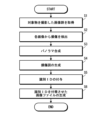
- An information processing apparatus including a processor, wherein the processor acquires a group of images captured with overlapping shooting ranges, synthesizes the acquired image group, and from the result of the synthesis process, images of the same shooting target are obtained.
- An information processing device that assigns the same identification information and attaches it to an image as supplementary information.
- the processor performs three-dimensional synthesis processing on the acquired image group, extracts regions that form the same surface of the object from the results of the three-dimensional synthesis processing, and assigns the same identification information to the images that form the extracted regions. and attached to the image as additional information.
- the processor performs three-dimensional synthesis processing on the obtained image group, extracts the same member region of the target object from the result of the three-dimensional synthesis processing, gives the same identification information to the images constituting the extracted region,
- the information processing apparatus according to (1) which is added to an image as additional information.
- One information processing device One information processing device.
- the image analysis result information includes at least one of detection result information by image analysis, type determination result information by image analysis, and measurement result information by image analysis.
- Information on measurement results by image analysis includes at least measurement result information on defect size, measurement result information on damage size, measurement result information on defect shape, and measurement result information on damage shape.
- the information processing device according to any one of (8) to (10), including one.
- An image data structure including an image and supplementary information, the supplementary information including identification information for identifying a photographing target.
- desired images can be easily retrieved.
- a diagram showing an example of a hardware configuration of an inspection support device Block diagram of the main functions of the inspection support device Conceptual diagram of the data structure of an image file with an identification ID Diagram showing the schematic structure of the floor slab A diagram showing an example of the photographing procedure of a coffer Flowchart showing procedures for creating a damage diagram, assigning an identification ID, and recording A diagram showing an example of an image that has undergone panorama synthesis processing A diagram showing an example of a damage diagram Conceptual diagram of assignment of identification ID A block diagram of the main functions of the inspection support device when the user inputs the information of the identification ID to be assigned to the image.
- Block diagram of the main functions of the inspection support device Block diagram of functions possessed by the 3D synthesis processing unit A diagram showing an example of a three-dimensional model A diagram showing an example of the extraction result of regions that form the same surface
- Conceptual diagram of assignment of identification ID Flowchart showing procedures for generating a three-dimensional model, assigning an identification ID, and recording
- Block diagram of the main functions of the inspection support device A diagram showing an example of a member identification result
- Conceptual diagram of assignment of identification ID Flowchart showing procedures for generating a three-dimensional model, assigning an identification ID, and recording
- the information processing apparatus assigns the same identification ID (identity/identification) to images of the same shooting target, and uses the identification ID to search for a desired image.
- the information processing device assigns the same identification ID to images of the same member, thereby enabling image retrieval for each member.
- the information processing apparatus assigns the same identification ID to the images forming the combined area when acquiring a group of images obtained by dividing and photographing one plane of a structure and performing panorama synthesis.
- the information processing apparatus regards the images forming the combined area as images of the same surface of the same member, and assigns the same identification ID to the images.
- the inspection support device acquires a group of images obtained by dividing and photographing one plane of the structure to be inspected, performs panorama synthesis processing on the acquired image group, and analyzes individual images to automatically extract damage. Then, the inspection support device automatically creates a damage diagram based on the extracted damage information and the panoramically synthesized image.
- a damage diagram is a diagram describing the state of damage to a structure.
- division photography means that the object is divided into a plurality of regions and photographed. In split shooting, shooting is performed with the shooting ranges overlapping between adjacent images so that images after shooting can be combined.
- the inspection support device of the present embodiment is configured as a device that acquires a group of images obtained by separately photographing one plane of a structure, and automatically generates a damage diagram based on the acquired image group.
- FIG. 1 is a diagram showing an example of the hardware configuration of the inspection support device.
- the inspection support device 10 includes a CPU (Central Processing Unit) 11, a RAM (Random Access Memory) 12, a ROM (Read Only Memory) 13, an auxiliary storage device 14, an input device 15, a display device 16 and It is composed of a computer having an input/output interface (I/F) 17 and the like.
- the inspection support device 10 is an example of an information processing device.
- the auxiliary storage device 14 is composed of, for example, an HDD (Hard Disk Drive), an SSD (Solid State Drive), or the like.
- a program (information processing program) executed by the CPU 11 and data necessary for processing are stored in the auxiliary storage device 14 .
- the input device 15 is composed of, for example, a keyboard, mouse, touch panel, and the like.
- the display device 16 is configured by, for example, a display such as a liquid crystal display (Liquid Crystal Display) or an organic EL display (Organic Light Emitting Diode display).
- a group of divided images of the structure to be inspected are captured by the inspection support device 10 via the input/output interface 17 .
- a structure to be inspected is an example of an object.
- Fig. 2 is a block diagram of the main functions of the inspection support device.
- the inspection support device 10 includes an image acquisition unit 10A, a damage detection unit 10B, a panoramic synthesis processing unit 10C, a damage diagram generation unit 10D, an identification ID assigning unit 10E, an identification ID recording control unit 10F, and other functions. have These functions are realized by the CPU 11 executing a predetermined program (information processing program).
- the image acquisition unit 10A performs processing for acquiring a group of images obtained by dividing and photographing the structure. As described above, the group of images obtained by dividing and photographing the structure is captured by the inspection support device 10 via the input/output interface 17 .
- the damage detection unit 10B analyzes each image acquired by the image acquisition unit 10A and detects damage.
- a known method can be adopted for detecting damage by image analysis.
- a method of detecting damage using a trained model (recognizer) can be adopted.
- a machine learning algorithm for generating a recognizer is not particularly limited.
- algorithms using neural networks such as RNN (Recurrent Neural Network), CNN (Convolutional Neural Network) or MLP (Multilayer Perceptron) can be employed.
- Information about the detected damage is stored in association with the image from which it was detected.
- cracks marking if cracks are marked
- the panorama synthesis processing unit 10C performs processing for panorama synthesis of a group of dividedly photographed images. Since panorama synthesis itself is a well-known technology, detailed description thereof will be omitted.
- the panorama synthesis processing unit 10C detects corresponding points between images, and synthesizes a group of images that have been divided and photographed. At this time, the panorama synthesis processing unit 10C performs correction such as scaling correction, tilt correction, and rotation correction on each image as necessary.
- the damage diagram generation unit 10D performs processing for creating a damage diagram.
- the damage diagram generation unit 10D generates, as a damage diagram, an image obtained by tracing the damage on the panorama-combined image.
- the damage diagram generation unit 10D generates a damage diagram based on the panorama synthesis process result and the damage detection result. Note that the technique itself for automatically generating a damage diagram is a known technique, so detailed description thereof will be omitted.
- the generated damage diagram is output to the display device 16.
- the generated damage diagram is stored in the auxiliary storage device 14 according to instructions from the user.
- the identification ID assigning unit 10E performs a process of assigning an identification ID to the group of images acquired by the image acquiring unit 10A based on the panorama synthesis processing result. Specifically, the identification ID assigning unit 10E assigns the same identification ID to the images forming the combined area. The images forming the synthesized area are considered to be images of the same surface of the same member. Therefore, the same identification ID is assigned to images of the same imaging target.
- the identification ID is an example of identification information.
- the identification ID assigning unit 10E generates and assigns an identification ID according to a predetermined generation rule. For example, the identification ID assigning unit 10E configures an identification ID with a four-digit number, and generates and assigns an identification ID by sequentially incrementing the numbers from "0001".
- an identification ID is not assigned to images that have not been synthesized. Predetermined information may be added to the image that has not been synthesized so that it can be distinguished from other images.
- the identification ID recording control unit 10F attaches the identification ID assigned to each image by the identification ID assigning unit 10E to the image as additional information (metadata). Specifically, the identification ID recording control unit 10F adds the assigned identification ID to the image data of each image as supplementary information, and shapes the image data according to the format of the image file. For example, Exif (Exchangeable Image File Format) can be adopted as the image file format.
- FIG. 3 is a conceptual diagram of the data structure of an image file attached with an identification ID.
- the image file includes image data and supplementary information.
- the incidental information includes identification ID information.
- the identification ID is recorded in MakerNotes, for example.
- a bridge consists of parts such as superstructure, substructure, bearings, roads, drainage facilities, inspection facilities, attachments, and wing retaining walls.
- Each part is composed of a plurality of members.
- the superstructure consists of members such as main girders, main girder gel bar sections, horizontal girders, vertical girders, floor slabs, opposing grooves, horizontal grooves, outer cables, PC (Prestressed Concrete) anchorages, and the like.
- the lower structure consists of members such as piers (pillars, walls, beams, corners, joints), abutments (parapet walls, vertical walls, wing walls), and foundations.
- the bearing part consists of a bearing body, anchor bolts, a bridge fall prevention system, mortar mortar, and concrete pedestal.
- Roads are composed of balustrades, protective fences, ground guards, median strips, expansion devices, sound insulation facilities, lighting facilities, signage facilities, curbs, pavements, and other members. Drainage facilities are composed of members such as drainage basins
- a bridge is an example of an object in this embodiment.
- a floor slab is an example of a member.
- the inspection target (floor slab) is photographed on site. Then, a diagram of damage is created based on the group of images obtained by the imaging. In this embodiment, an identification ID is further assigned to each image obtained by photographing.
- FIG. 4 is a diagram showing a schematic configuration of a floor slab.
- floor slabs 1 are inspected every coffer 2.
- the coffer 2 is one section of the floor slab 1 separated by the main girder 3 and the cross girder 4 .
- the floor slab 1 and the coffer 2 are examples of areas that form the same surface.
- the number (Ds001) attached to the floor slab 1 is information for identifying the floor slab 1.
- the numbers (0101, 0102, . . . ) attached to each case 2 are information for identifying each case 2.
- the coffer 2 is photographed separately. That is, the coffer 2 is divided into a plurality of areas, and photographed in a plurality of times.
- FIG. 5 is a diagram showing an example of the procedure for photographing a coffer.
- reference character F is a frame indicating the shooting range.
- a photographer inspection engineer faces the floor slab, which is the surface to be inspected, and takes an image from a fixed distance. Also, the photographer shoots adjacent shooting areas so that they partially overlap each other (for example, shoot with an overlap of 30% or more).
- the panorama synthesis processing unit 10C can perform panorama synthesis of the captured images with high accuracy.
- FIG. 6 is a flow chart showing the procedure for creating a damage diagram, assigning an identification ID, and recording.
- an image of the object to be inspected is acquired (step S1).
- a group of images obtained by dividing and photographing one coffer 2 of the floor slab 1 is acquired.
- each acquired image is analyzed to detect damage that appears on the surface of the object (step S2).
- cracks are detected as damage.
- FIG. 7 is a diagram showing an example of an image subjected to panorama synthesis processing. As shown in FIG. 7, an image I showing the entire coffer is generated by panorama synthesis processing.
- FIG. 8 is a diagram showing an example of a damage diagram.
- a damage diagram D is generated as a diagram tracing the damage from the panorama-synthesized image I.
- FIG. The generated damage diagram D is stored in the auxiliary storage device 14 . Further, the generated damage diagram D is displayed on the display device 16 as required.
- FIG. 9 is a conceptual diagram of assigning an identification ID. As shown in FIG. 9, the same identification ID is given to each image i that constitutes an image of one coffer. The example shown in FIG. 9 shows an example in which "0001" is assigned as the identification ID.
- an image file attached with the assigned identification ID is generated (step S6).
- an image file is generated that includes identification ID information in additional information (metadata) (see FIG. 3).
- the generated image file is stored in the auxiliary storage device 14 .
- an identification ID is assigned to each image.
- the identification ID is assigned using the result of panorama synthesis processing, and the same identification ID is assigned to images of the same shooting target.
- the assigned identification ID is added to the image as additional information. This makes it possible to search for images using only the incidental information. In other words, it is possible to extract images of the same object by using only the incidental information. As a result, when an inspection engineer prepares a report or the like to which an image is attached, the work can be facilitated.
- the identification ID is automatically generated according to a predetermined generation rule, but the method of generating the identification ID to be assigned to the image is not limited to this.
- a user inspection engineer
- FIG. 10 is a block diagram of the main functions of the inspection support device when the user inputs the identification ID information to be assigned to the image.
- the inspection support device 10 of this example further has the function of an identification ID input reception section 10G.
- the identification ID input reception unit 10G performs processing for receiving input of an identification ID to be assigned to an image.
- the identification ID input reception unit 10G receives input of identification ID information from the input device 15 .
- the user inputs a group of images to be processed into the inspection support device 10
- the user inputs information of an identification ID to be assigned from the input device 15 .
- the acquired identification ID information is added to the identification ID assigning unit 10E.
- the identification ID assigning unit 10E assigns the identification ID input by the user when assigning the identification ID.
- the user may input the identification ID to be given to the image.
- the identification ID given to the image it is preferable to use, for example, identification information given to each member. This allows the user to search for images for each member.
- identification information For example, in the case of floor slabs, information obtained by combining identification information given to each floor slab and identification information given to a coffer constituting each floor slab can be used as identification information.
- identification information For example, in the floor slab with the identification information "Ds001”, if the coffer with the identification information "0202" is targeted, "Ds001-0202" is assigned as the identification ID.
- the target image group can be extracted more easily. For example, it is possible to perform a search in units of floor slabs using floor slab identification information and a search in units of spaces using space identification information.
- the identification information is attached, but it is also possible to attach other information.
- the result of image analysis can be attached.
- information on the detection result of damage can be added.
- information on the presence or absence of damage is attached.
- the image analysis performed on the acquired image includes not only damage detection but also defect detection. Further, when detecting damage and/or defects, the type of damage and/or defects may be determined by image analysis. Further, image analysis may be used to measure the size (length, width, area, etc.) of damage and/or defects. Further, image analysis may be used to measure the shape of damage and/or defects. It should be noted that performing these processes by image analysis is a well-known technique per se, so detailed description thereof will be omitted.
- information on the determination result may be attached to the image.
- the information of the measurement results may be attached to the image.
- damage includes, for example, cracks, delamination, exposure of reinforcing bars, water leakage, free lime, falling off, floor slab cracks, floats, and the like.
- corrosion, cracks, loosening, falling off, breakage, deterioration of anticorrosion function, etc. are included.
- damage to repair and reinforcement materials abnormality of anchorage, discoloration, deterioration, water leakage, water retention, abnormal deflection, deformation, loss, clogging with earth and sand, subsidence, movement, inclination, scouring etc. are exemplified.
- the damage includes irregularities in clearance, irregularities in the road surface, irregularities in pavement, functional failure of bearings, and the like.
- FIG. 11 is a conceptual diagram of the data structure of an image file with analysis results attached.
- the incidental information attached to the image data includes the identification ID and the analysis result information.
- the analysis results include damage detection results (presence or absence of damage), types of damage (for example, cracks, delamination, exposure of reinforcing bars, water leakage, free lime, floating and discoloration, etc.), size of damage (for example, , width and length in the case of a crack), and information on the shape of the damage (for example, in the case of a crack, the crack pattern, etc.).
- the inspection support device of the present embodiment uses the result of the three-dimensional synthesis process to assign an identification ID to the image.
- the hardware configuration is the same as that of the inspection support device of the first embodiment. Therefore, only functions related to assigning an identification ID will be described here.
- FIG. 12 is a block diagram of the main functions of the inspection support device of this embodiment.
- the inspection support device 20 of the present embodiment has functions such as an image acquisition section 20A, a three-dimensional synthesis processing section 20B, a same plane area extraction section 20C, an identification ID provision section 20D and an identification ID recording control section 20E. Each function is realized by the CPU executing a predetermined program.
- the image acquisition unit 20A performs processing for acquiring a group of images obtained by dividing and photographing the structure.
- the inspection support device generates a three-dimensional model of an object from an image.
- images are acquired from which a three-dimensional model of the object can be generated.
- the inspection support device uses SfM (Structure from Motion) technology to generate a three-dimensional model of an object.
- SfM Structure from Motion
- multi-viewpoint images are required.
- a multi-viewpoint image is a group of images obtained by photographing an object from a plurality of viewpoints with overlapping photographing ranges.
- the 3D synthesis processing unit 20B performs 3D synthesis processing using the acquired image group, and performs processing for generating a 3D model of the target object.
- FIG. 13 is a block diagram of functions possessed by the three-dimensional synthesis processing unit.
- the 3D synthesis processing unit 20B has the functions of a point cloud data generation unit 20B1, a 3D patch model generation unit 20B2, and a 3D model generation unit 20B3.
- the point cloud data generation unit 20B1 analyzes the image group acquired by the image acquisition unit 20A and performs processing for generating three-dimensional point cloud data of feature points.
- the point cloud data generator 20B1 performs this process using SfM and MVS (Multi-View Stereo) techniques.
- SfM is a technology that performs "estimation of captured position and posture" and "three-dimensional reconstruction of feature points" from multiple images captured by a camera.
- SfM itself is a known technology.
- the outline of the processing is roughly as follows. First, a plurality of images (image group) to be processed are acquired. Next, feature points are detected from each acquired image. Matching feature points are then detected as corresponding points by comparing each feature point of the two image pairs. That is, feature point matching is performed. Then, from the detected corresponding points, the camera parameters (eg, fundamental matrix, fundamental matrix, intrinsic parameters, etc.) of the camera that captured the two image pairs are estimated. Next, the shooting position and orientation are estimated based on the estimated camera parameters.
- image group image group
- feature points are detected from each acquired image. Matching feature points are then detected as corresponding points by comparing each feature point of the two image pairs. That is, feature point matching is performed.
- the camera parameters eg, fundamental matrix, fundamental matrix, intrinsic parameters, etc.
- the three-dimensional positions of the feature points of the object are obtained. That is, three-dimensional restoration of feature points is performed. After this, bundle adjustment is performed as necessary. That is, in order to minimize the reprojection error of the point cloud, which is a set of the feature points in the three-dimensional coordinates, to the camera, the coordinates of the three-dimensional point cloud, the camera internal parameters (focal length, principal point) , the camera extrinsic parameters (position, rotation) are adjusted.
- the 3D points restored by SfM are specific 3D points and sparse.
- a general three-dimensional model is mostly composed of textures with low feature amounts (for example, walls).
- MVS attempts to restore 3D textures with low feature amounts that account for the majority.
- MVS uses the "shooting position and orientation" estimated by SfM to generate a dense point cloud.
- MVS itself is a known technology. Therefore, detailed description thereof is omitted.
- the restored shape and imaging position obtained by SfM are a point group represented by dimensionless coordinate values. Therefore, the shape cannot be quantitatively grasped from the obtained restored shape as it is. Therefore, it is necessary to give physical dimensions (actual dimensions).
- a known technique is adopted for this processing. For example, techniques such as extracting reference points (eg, ground control points) from an image and assigning physical dimensions can be employed.
- GCP Ground Control Point
- a Ground Control Point (GCP) is a landmark containing geospatial information (latitude, longitude, altitude) that is visible in a captured image. Therefore, in this case, it is necessary to set a reference point at the stage of photographing.
- the physical dimensions can be assigned using the distance measurement information.
- LIDAR Light Detection and Ranging or Laser Imaging Detection and Ranging
- SfM Sensor Detection and Ranging
- the 3D patch model generation unit 20B2 performs processing for generating a 3D patch model of the object based on the 3D point cloud data of the object generated by the point cloud data generation unit 20B1. Specifically, the 3D patch model generation unit 20B2 generates a patch (mesh) from the generated 3D point group to generate a 3D patch model. This makes it possible to express surface undulations with a small number of points. This processing is performed using a known technique such as, for example, three-dimensional Delaunay triangulation. Therefore, detailed description thereof will be omitted.
- the three-dimensional patch model generation unit 20B2 uses three-dimensional Delaunay triangulation to generate a TIN (Trainangular Irregular Network) model.
- TIN Trainangular Irregular Network
- a surface is represented by a set of triangles. That is, a patch is generated using a triangular mesh.
- the 3D model generation unit 20B3 generates a textured 3D model by performing texture mapping on the 3D patch model generated by the 3D patch model generation unit 20B2. This processing is performed by interpolating the space within each patch of the three-dimensional patch model with the captured image.
- the point cloud data generation unit 20B1 performs SfM and MVS processing. By this SfM and MVS processing, an image obtained by photographing an area corresponding to each patch and a corresponding position within the image can be obtained. Therefore, if the vertex of the generated surface can be observed, it is possible to associate the texture to be applied to that surface.
- the three-dimensional model generation unit 20B3 selects an image corresponding to each patch, and extracts an image of an area corresponding to the patch from the selected image as a texture. Specifically, the three-dimensional model generation unit 20B3 projects the vertices of the patch onto the selected image, and extracts the image of the area surrounded by the projected vertices as a texture. The 3D model generation unit 20B3 applies the extracted texture to the patch to generate a 3D model. That is, the 3D model generation unit 20B3 interpolates the space in the patch with the extracted texture to generate a 3D model. Color information is added to each patch by adding a texture to each patch. If the object has damage such as cracks, the damage is displayed at the corresponding position.
- FIG. 14 is a diagram showing an example of a three-dimensional model.
- Fig. 14 shows an example of a 3D model for a bridge.
- the generated three-dimensional model is stored in the auxiliary storage device 14 . Also, the three-dimensional model is displayed on the display device 16 as necessary.
- the coplanar area extraction unit 20C performs a process of extracting an area forming the same surface of the object from the results of the three-dimensional synthesis process.
- the “same plane” here means a plane that is recognized as the same plane when classified from the viewpoint of identifying the members of the structure.
- the same-plane region extracting unit 20C uses point cloud data acquired in the process of generating a three-dimensional model to perform a process of estimating a plane and extract regions forming the same plane. to extract In the process of estimating a plane, the coplanar area extraction unit 20C performs a process of estimating an approximate plane using, for example, the RANSAC (RANdom SAmple Consensus) method.
- RANSAC Random SAmple Consensus
- FIG. 15 is a diagram showing an example of the extraction result of the regions forming the same plane.
- the regions extracted as regions forming the same plane are given the same pattern.
- the identification ID assigning unit 20D performs a process of assigning an identification ID to each image based on the extraction result of the regions forming the same surface. Specifically, the identification ID assigning section 20D assigns the same identification ID to the images forming the extracted area.
- the image forming the extracted area is the image used for synthesis in the area.
- the image forming the extracted region is the image used for texture mapping.
- the regions extracted by the coplanar region extraction unit 20C are regions forming the same plane. Therefore, the same identification ID is given to the images forming the same surface.
- the images forming the same surface are images of the same surface, the same identification ID is given to the images of the same surface.
- the identification ID assigning unit 20D generates and assigns an identification ID according to a predetermined generation rule. For example, the identification ID assigning section 20D configures an identification ID with a four-digit number, and generates and assigns an identification ID by sequentially incrementing the numbers from "0001".
- FIG. 16 is a conceptual diagram of assigning an identification ID.
- the same identification ID is given to the images forming the regions extracted as the regions forming the same surface.
- the identification ID assigning unit 20D assigns an identification ID of 0001 to the group of images forming the pavement (road surface).
- an identification ID is not assigned to images that have not been used for synthesis. Predetermined information may be added to the image that has not been used for synthesis so that the image can be distinguished from other images.
- the identification ID recording control unit 20E appends the identification ID given to each image by the identification ID adding unit 20D to the image as additional information (metadata). Specifically, the identification ID recording control unit 20E adds the assigned identification ID as additional information to the image data of each image, and shapes the image data according to the format of the image file.
- FIG. 17 is a flow chart showing the procedure for generating a three-dimensional model, assigning an identification ID, and recording.
- an image of the object is acquired (step S11).
- this image is a multi-viewpoint image, and is an image obtained by photographing an object from a plurality of viewpoints with overlapping photographing ranges.
- step S12 three-dimensional synthesis processing is performed on the acquired image group.
- a three-dimensional model of the target is generated (see FIG. 14).
- the generated three-dimensional model is stored in the auxiliary storage device 14 .
- step S13 extraction processing of the coplanar region is performed from the result of the three-dimensional synthesis processing. That is, in the generated three-dimensional model, a process of extracting regions forming the same surface is performed (see FIG. 15).
- an identification ID is given to each image based on the extraction result of the coplanar area (step S14).
- the same identification ID is assigned to images forming the same surface (see FIG. 16).
- the same identification ID is assigned to images of the same surface.
- an image file attached with the assigned identification ID is generated (step S15).
- an image file is generated that includes identification ID information in additional information (metadata) (see FIG. 3).
- the generated image file is stored in the auxiliary storage device 14 .
- an identification ID is assigned to each image.
- the identification ID is assigned using the result of the three-dimensional synthesis processing, and the same identification ID is assigned to images obtained by photographing the same surface.
- the assigned identification ID is attached to the image as additional information. This makes it possible to search for images using only the incidental information. That is, the inspection support device 20 can extract a group of images of a specific surface by using only the incidental information. As a result, when an inspection engineer prepares a report or the like to which an image is attached, the work can be facilitated.
- the user can input an identification ID to be assigned to an image.
- FIG. 18 is a block diagram of the main functions of the inspection support device when the user inputs the identification ID information to be assigned to the image.
- the inspection support device 20 of this example further has the function of an identification ID input receiving section 20F.
- the identification ID input reception unit 20F performs processing for receiving input of identification IDs to be assigned to images.
- the identification ID input reception unit 20F receives input of identification ID via the display device 16 and the input device 15 .
- the inspection support device 20 causes the display device 16 to display the generated three-dimensional model, and the identification ID input reception unit 20F receives designation of an area to which an identification ID is assigned on the screen.
- the specifiable area is an area extracted as an area forming the same plane.
- the identification ID input reception unit 20F receives from the input device 15 an input of an identification ID to be assigned to the specified area.
- the identification ID input reception unit 20F receives input of an identification ID to be assigned to each region extracted by the same plane region extraction unit 20C.
- information other than the identification ID can be attached to the image.
- information on the result may be included in additional information.
- the hardware configuration is the same as that of the inspection support device of the first embodiment. Therefore, only functions related to assigning an identification ID will be described here.
- FIG. 19 is a block diagram of the main functions of the inspection support device of this embodiment.
- the inspection support device 30 of the present embodiment has functions such as an image acquisition section 30A, a three-dimensional synthesis processing section 30B, a member identification section 30C, an identification ID provision section 30D, and an identification ID recording control section 30E. Each function is realized by the CPU executing a predetermined program.
- the image acquisition unit 30A performs processing for acquiring a group of images obtained by dividing and photographing the structure.
- a multi-viewpoint image is obtained by photographing an object from a plurality of viewpoints with overlapping photographing ranges.
- the 3D synthesis processing unit 30B performs 3D synthesis processing using the acquired image group, and performs processing for generating a 3D model of the target.
- the function of the three-dimensional synthesis processing section 30B is the same as that of the second embodiment. Therefore, description thereof is omitted.
- the member identification unit 30C identifies the members that make up the structure from the results of the three-dimensional synthesis processing, and performs processing to extract regions that make up the same members.
- the member identification unit 30C uses a learned model to perform processing for identifying members from the point cloud data of the target object.
- the member identification unit 30C identifies the members that make up the object using a trained image recognition model from images (point cloud projection images) obtained by projecting the point cloud data of the object from various viewpoints. . That is, the member identification unit 30C identifies members such as main girders, floor slabs, and piers that constitute the bridge.
- a point cloud projection image is generated, for example, by projecting point cloud data onto a plane from viewpoints at various angles.
- an image segmentation CNN eg, SegNet model
- point cloud data to which member information is added is learned as teacher data.
- the teacher data is generated according to the type of member to be identified.
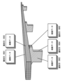
- FIG. 20 is a diagram showing an example of the member identification result.
- FIG. 20 shows an example in which a pavement (road surface) Pm, a main girder Mg, and a bridge pier P are identified as members constituting a bridge.
- the identification ID assigning unit 30D performs a process of assigning an identification ID to each image based on the member identification result. Specifically, the identification ID assigning section 30D assigns the same identification ID to the images forming the extracted area.
- the image forming the extracted area is the image used for synthesis in the area.
- the image forming the extracted region is the image used for texture mapping.
- the regions extracted by the member identification unit 30C are regions that constitute the same member. Therefore, the same identification ID is assigned to the images forming the same member.
- the same identification ID is given to the images of the same member.
- the identification ID assigning unit 30D generates and assigns a different identification ID for each member. For example, the identification ID assigning section 30D generates and assigns an identification ID by combining a symbol identifying a member and a four-digit number. Symbols identifying members are used to distinguish between different members. A four-digit number is used to distinguish between identical members.
- FIG. 21 is a conceptual diagram of assigning an identification ID.
- FIG. 21 shows an example in which identification IDs of "Pm0001" are given to the pavement (road surface), "Mg0001" to the main girder, and "P0001", “P0002", and “P0003” to the three piers, respectively. showing.
- the pavement identification ID is formed by combining the pavement identification symbol "Pm” and a four-digit number.
- the identification ID of the main girder is formed by combining "Mg", which is the identification symbol of the main girder, and a 4-digit number.
- the pier identification ID is formed by combining a pier identification symbol "P” and a four-digit number. In this way, by forming the identification ID of each member by combining the identification symbols assigned to each member, subsequent retrieval can be facilitated.
- predetermined information is added to images that have not been used for synthesis so that they can be distinguished from other images.
- the identification ID recording control unit 30E appends the identification ID given to each image by the identification ID adding unit 30D to the image as additional information (metadata). Specifically, the identification ID recording control unit 30E adds the assigned identification ID to the image data of each image as supplementary information, and shapes the image data according to the format of the image file.
- FIG. 22 is a flow chart showing the procedure for generating a three-dimensional model, assigning an identification ID, and recording.
- an image of the object is acquired (step S21).
- this image is a multi-viewpoint image, and is an image obtained by photographing an object from a plurality of viewpoints with overlapping photographing ranges.
- step S22 three-dimensional synthesis processing is performed on the acquired image group.
- a three-dimensional model of the target is generated (see FIG. 14).
- the generated three-dimensional model is stored in the auxiliary storage device 14 .
- step S23 member identification processing is performed based on the results of the three-dimensional synthesis processing (step S23). That is, the members are identified in the generated three-dimensional model, and the regions forming each member are extracted (see FIG. 20).
- an identification ID is given to each image based on the identification result of the member (step S24). That is, the same identification ID is given to the images constituting the same member (see FIG. 21). As a result, the same identification ID is assigned to images of the same member.
- an image file attached with the assigned identification ID is generated (step S25).
- an image file is generated that includes identification ID information in additional information (metadata) (see FIG. 3).
- the generated image file is stored in the auxiliary storage device 14 .
- an identification ID is assigned to each image.
- the identification ID is assigned using the result of the three-dimensional synthesis processing, and the same identification ID is assigned to images of the same member.
- the assigned identification ID is attached to the image as additional information. This makes it possible to search for images using only the incidental information. That is, the inspection support device 30 can extract a group of images of a specific member using only the incidental information. As a result, when an inspection engineer prepares a report or the like to which an image is attached, the work can be facilitated.
- [Member identification processing] a trained model (image recognition model) is used to identify members from point cloud data, but the method for identifying members is not limited to this. It is also possible to adopt a configuration in which members are identified from a three-dimensional model.
- information other than the identification ID can be attached to the image.
- information on the result may be included in additional information.
- the identification ID may be attached to the image data, and its specific data structure is not particularly limited.
- the identification ID since the identification ID is used for searching, it must be attached to the image data in a searchable state. In particular, it is preferable to have a structure that can be searched with commercially available software or the like.
- Hardware that implements the information processing apparatus can be configured with various processors.
- the various processors include CPUs (Central Processing Units), which are general-purpose processors that execute programs and function as various processing units, and FPGAs (Field Programmable Gate Arrays), which are processors whose circuit configuration can be changed after manufacturing.
- Programmable Logic Devices (PLDs), ASICs (Application Specific Integrated Circuits), and other dedicated electric circuits, which are processors having circuit configurations specially designed to execute specific processing, are included.
- One processing unit that constitutes the inspection support device may be configured by one of the various processors described above, or may be configured by two or more processors of the same type or different types.
- one processing unit may be composed of a plurality of FPGAs or a combination of a CPU and an FPGA.
- a plurality of processing units may be configured by one processor.
- a single processor is configured by combining one or more CPUs and software.
- a processor functions as multiple processing units.
- SoC System On Chip
- SoC System On Chip
- the various processing units are configured using one or more of the above various processors as a hardware structure.
- the hardware structure of these various processors is, more specifically, an electric circuit combining circuit elements such as semiconductor elements.
Landscapes
- Engineering & Computer Science (AREA)
- Physics & Mathematics (AREA)
- General Physics & Mathematics (AREA)
- Theoretical Computer Science (AREA)
- Computer Vision & Pattern Recognition (AREA)
- Geometry (AREA)
- Computer Graphics (AREA)
- Software Systems (AREA)
- Multimedia (AREA)
- Quality & Reliability (AREA)
- Image Processing (AREA)
Priority Applications (4)
| Application Number | Priority Date | Filing Date | Title |
|---|---|---|---|
| EP22872615.4A EP4407552A4 (en) | 2021-09-22 | 2022-08-19 | INFORMATION PROCESSING DEVICE, METHOD AND PROGRAM AS WELL AS IMAGE DATA STRUCTURE |
| CN202280061698.0A CN117940950A (zh) | 2021-09-22 | 2022-08-19 | 信息处理装置、方法及程序、以及图像数据结构 |
| JP2023549417A JPWO2023047859A1 (https=) | 2021-09-22 | 2022-08-19 | |
| US18/601,950 US20240257315A1 (en) | 2021-09-22 | 2024-03-11 | Information processing apparatus, method, and program, and image data structure |
Applications Claiming Priority (2)
| Application Number | Priority Date | Filing Date | Title |
|---|---|---|---|
| JP2021-154105 | 2021-09-22 | ||
| JP2021154105 | 2021-09-22 |
Related Child Applications (1)
| Application Number | Title | Priority Date | Filing Date |
|---|---|---|---|
| US18/601,950 Continuation US20240257315A1 (en) | 2021-09-22 | 2024-03-11 | Information processing apparatus, method, and program, and image data structure |
Publications (1)
| Publication Number | Publication Date |
|---|---|
| WO2023047859A1 true WO2023047859A1 (ja) | 2023-03-30 |
Family
ID=85719452
Family Applications (1)
| Application Number | Title | Priority Date | Filing Date |
|---|---|---|---|
| PCT/JP2022/031372 Ceased WO2023047859A1 (ja) | 2021-09-22 | 2022-08-19 | 情報処理装置、方法及びプログラム、並びに、画像データ構造 |
Country Status (5)
| Country | Link |
|---|---|
| US (1) | US20240257315A1 (https=) |
| EP (1) | EP4407552A4 (https=) |
| JP (1) | JPWO2023047859A1 (https=) |
| CN (1) | CN117940950A (https=) |
| WO (1) | WO2023047859A1 (https=) |
Cited By (2)
| Publication number | Priority date | Publication date | Assignee | Title |
|---|---|---|---|---|
| CN117934382A (zh) * | 2023-12-27 | 2024-04-26 | 北京交科公路勘察设计研究院有限公司 | 基于图像分析的高速公路护栏检测方法及系统 |
| WO2025205149A1 (ja) * | 2024-03-25 | 2025-10-02 | 富士フイルム株式会社 | 情報処理装置、情報処理方法、プログラム、及び記録媒体 |
Citations (6)
| Publication number | Priority date | Publication date | Assignee | Title |
|---|---|---|---|---|
| JP2015001756A (ja) * | 2013-06-13 | 2015-01-05 | 株式会社日立製作所 | 状態変化管理システム、状態変化管理サーバ及び状態変化管理端末 |
| JP2016082441A (ja) * | 2014-10-17 | 2016-05-16 | ソニー株式会社 | 制御装置、制御方法及びコンピュータプログラム |
| JP2016125846A (ja) * | 2014-12-26 | 2016-07-11 | 古河機械金属株式会社 | データ処理装置、データ処理方法、及び、プログラム |
| WO2017119202A1 (ja) * | 2016-01-06 | 2017-07-13 | 富士フイルム株式会社 | 構造物の部材特定装置及び方法 |
| WO2017217185A1 (ja) * | 2016-06-14 | 2017-12-21 | 富士フイルム株式会社 | サーバ装置、画像処理システム及び画像処理方法 |
| JP2020160944A (ja) | 2019-03-27 | 2020-10-01 | 富士通株式会社 | 点検作業支援装置、点検作業支援方法及び点検作業支援プログラム |
Family Cites Families (6)
| Publication number | Priority date | Publication date | Assignee | Title |
|---|---|---|---|---|
| JP2015233250A (ja) * | 2014-06-10 | 2015-12-24 | キヤノン株式会社 | 画像処理装置及びその制御方法 |
| KR101775272B1 (ko) * | 2016-04-11 | 2017-09-06 | 재단법인 다차원 스마트 아이티 융합시스템 연구단 | 멀티 애퍼처 카메라에서 스파스 깊이 이미지들의 깊이 개선 방법 및 시스템 |
| JP6807459B2 (ja) * | 2017-07-25 | 2021-01-06 | 富士フイルム株式会社 | 損傷図作成方法、損傷図作成装置、損傷図作成システム、及び記録媒体 |
| CN108921811B (zh) * | 2018-04-03 | 2020-06-30 | 阿里巴巴集团控股有限公司 | 检测物品损伤的方法和装置、物品损伤检测器 |
| CN115104128B (zh) * | 2020-03-02 | 2025-03-21 | 富士胶片株式会社 | 图像处理装置、图像处理方法及图像处理程序 |
| US11954846B2 (en) * | 2020-06-16 | 2024-04-09 | Elementary Robotics, Inc. | Explainability and complementary information for camera-based quality assurance inspection processes |
-
2022
- 2022-08-19 JP JP2023549417A patent/JPWO2023047859A1/ja active Pending
- 2022-08-19 WO PCT/JP2022/031372 patent/WO2023047859A1/ja not_active Ceased
- 2022-08-19 EP EP22872615.4A patent/EP4407552A4/en active Pending
- 2022-08-19 CN CN202280061698.0A patent/CN117940950A/zh active Pending
-
2024
- 2024-03-11 US US18/601,950 patent/US20240257315A1/en active Pending
Patent Citations (6)
| Publication number | Priority date | Publication date | Assignee | Title |
|---|---|---|---|---|
| JP2015001756A (ja) * | 2013-06-13 | 2015-01-05 | 株式会社日立製作所 | 状態変化管理システム、状態変化管理サーバ及び状態変化管理端末 |
| JP2016082441A (ja) * | 2014-10-17 | 2016-05-16 | ソニー株式会社 | 制御装置、制御方法及びコンピュータプログラム |
| JP2016125846A (ja) * | 2014-12-26 | 2016-07-11 | 古河機械金属株式会社 | データ処理装置、データ処理方法、及び、プログラム |
| WO2017119202A1 (ja) * | 2016-01-06 | 2017-07-13 | 富士フイルム株式会社 | 構造物の部材特定装置及び方法 |
| WO2017217185A1 (ja) * | 2016-06-14 | 2017-12-21 | 富士フイルム株式会社 | サーバ装置、画像処理システム及び画像処理方法 |
| JP2020160944A (ja) | 2019-03-27 | 2020-10-01 | 富士通株式会社 | 点検作業支援装置、点検作業支援方法及び点検作業支援プログラム |
Non-Patent Citations (1)
| Title |
|---|
| See also references of EP4407552A4 |
Cited By (2)
| Publication number | Priority date | Publication date | Assignee | Title |
|---|---|---|---|---|
| CN117934382A (zh) * | 2023-12-27 | 2024-04-26 | 北京交科公路勘察设计研究院有限公司 | 基于图像分析的高速公路护栏检测方法及系统 |
| WO2025205149A1 (ja) * | 2024-03-25 | 2025-10-02 | 富士フイルム株式会社 | 情報処理装置、情報処理方法、プログラム、及び記録媒体 |
Also Published As
| Publication number | Publication date |
|---|---|
| EP4407552A1 (en) | 2024-07-31 |
| JPWO2023047859A1 (https=) | 2023-03-30 |
| EP4407552A4 (en) | 2025-01-15 |
| CN117940950A (zh) | 2024-04-26 |
| US20240257315A1 (en) | 2024-08-01 |
Similar Documents
| Publication | Publication Date | Title |
|---|---|---|
| Kong et al. | Preserving our heritage: A photogrammetry-based digital twin framework for monitoring deteriorations of historic structures | |
| Chen et al. | UAV bridge inspection through evaluated 3D reconstructions | |
| Erkal et al. | Laser-based surface damage detection and quantification using predicted surface properties | |
| Alshawabkeh | Linear feature extraction from point cloud using color information | |
| JP6805351B2 (ja) | 損傷データ編集装置、損傷データ編集方法、およびプログラム | |
| Hsu et al. | Defect inspection of indoor components in buildings using deep learning object detection and augmented reality | |
| Marzouk | Using 3D laser scanning to analyze heritage structures: The case study of egyptian palace | |
| US20240257315A1 (en) | Information processing apparatus, method, and program, and image data structure | |
| JP7752625B2 (ja) | 構造物の点検支援装置、構造物の点検支援方法、及びプログラム | |
| Wittich et al. | Characterization of full-scale, human-form, culturally important statues: case study | |
| US20230260098A1 (en) | Structure inspection assistance apparatus, structure inspection assistance method, and program | |
| Shan et al. | Feasibility of Accurate Point Cloud Model Reconstruction for Earthquake‐Damaged Structures Using UAV‐Based Photogrammetry | |
| Zhu et al. | LiDAR-RGB data fusion for four-dimensional UAV-based monitoring of reinforced concrete bridge construction: case study of the fern hollow bridge reconstruction | |
| Napolitano et al. | Quantifying the Differences in Documentation and Modeling Levels for Building Pathology and Diagnostics: R. Napolitano et al. | |
| KR102793705B1 (ko) | 딥러닝 이미지 분석을 통한 철탑 변위 진단 시스템 및 방법 | |
| Chen et al. | Integrating UAV photogrammetry and terrestrial laser scanning for three-dimensional geometrical modeling of post-earthquake county of Beichuan | |
| Camp et al. | Large structures: which solutions for health monitoring? | |
| CN117098971A (zh) | 图像处理装置、图像处理方法及图像处理程序 | |
| Xu et al. | Semantic-guided automatic data acquisition for Terrestrial Laser Scanners in Civil Engineering | |
| Majidi et al. | Intelligent 3D crack reconstruction using close range photogrammetry imagery | |
| US20240040247A1 (en) | Method for capturing image, method for processing image, image capturing system, and information processing system | |
| Saksena et al. | Implementation of laser scanning technology for digital asset management of bridges in Indonesia: A case study of Pulau Balang bridge in east Kalimantan | |
| Srivastava et al. | UAV-Based Visual Remote Sensing for Automated Building Inspection | |
| Buatik et al. | 3D model-based image registration for change detection in historical structures via unmanned aerial vehicle | |
| Zhu et al. | Comparison of civil infrastructure optical-based spatial data acquisition techniques |
Legal Events
| Date | Code | Title | Description |
|---|---|---|---|
| 121 | Ep: the epo has been informed by wipo that ep was designated in this application |
Ref document number: 22872615 Country of ref document: EP Kind code of ref document: A1 |
|
| WWE | Wipo information: entry into national phase |
Ref document number: 2023549417 Country of ref document: JP |
|
| WWE | Wipo information: entry into national phase |
Ref document number: 202280061698.0 Country of ref document: CN |
|
| WWE | Wipo information: entry into national phase |
Ref document number: 2022872615 Country of ref document: EP |
|
| NENP | Non-entry into the national phase |
Ref country code: DE |
|
| ENP | Entry into the national phase |
Ref document number: 2022872615 Country of ref document: EP Effective date: 20240422 |