WO2023047702A1 - 液状コンプレッションモールド材、電子部品、半導体装置、および半導体装置の製造方法 - Google Patents
液状コンプレッションモールド材、電子部品、半導体装置、および半導体装置の製造方法 Download PDFInfo
- Publication number
- WO2023047702A1 WO2023047702A1 PCT/JP2022/021246 JP2022021246W WO2023047702A1 WO 2023047702 A1 WO2023047702 A1 WO 2023047702A1 JP 2022021246 W JP2022021246 W JP 2022021246W WO 2023047702 A1 WO2023047702 A1 WO 2023047702A1
- Authority
- WO
- WIPO (PCT)
- Prior art keywords
- compression molding
- epoxy resin
- liquid compression
- mass
- filler
- Prior art date
Links
- 238000000748 compression moulding Methods 0.000 title claims abstract description 64
- 239000007788 liquid Substances 0.000 title claims abstract description 52
- 239000012778 molding material Substances 0.000 title claims abstract description 40
- 239000004065 semiconductor Substances 0.000 title claims description 37
- 238000004519 manufacturing process Methods 0.000 title description 9
- 239000003822 epoxy resin Substances 0.000 claims abstract description 94
- 229920000647 polyepoxide Polymers 0.000 claims abstract description 94
- 239000000945 filler Substances 0.000 claims abstract description 57
- 229920001971 elastomer Polymers 0.000 claims abstract description 56
- 239000000806 elastomer Substances 0.000 claims abstract description 49
- 239000000203 mixture Substances 0.000 claims abstract description 33
- 238000002156 mixing Methods 0.000 claims abstract description 32
- 239000000463 material Substances 0.000 claims description 82
- 239000003795 chemical substances by application Substances 0.000 claims description 33
- LNEPOXFFQSENCJ-UHFFFAOYSA-N haloperidol Chemical compound C1CC(O)(C=2C=CC(Cl)=CC=2)CCN1CCCC(=O)C1=CC=C(F)C=C1 LNEPOXFFQSENCJ-UHFFFAOYSA-N 0.000 claims description 26
- 239000000126 substance Substances 0.000 claims description 19
- -1 nitrogen-containing heterocyclic compound Chemical class 0.000 claims description 18
- 239000000758 substrate Substances 0.000 claims description 16
- 239000003566 sealing material Substances 0.000 claims description 9
- 239000007787 solid Substances 0.000 claims description 8
- ISWSIDIOOBJBQZ-UHFFFAOYSA-N phenol group Chemical group C1(=CC=CC=C1)O ISWSIDIOOBJBQZ-UHFFFAOYSA-N 0.000 claims description 7
- 150000008065 acid anhydrides Chemical class 0.000 claims description 6
- 239000004844 aliphatic epoxy resin Substances 0.000 claims description 5
- 150000001412 amines Chemical class 0.000 claims description 5
- 125000003118 aryl group Chemical group 0.000 claims description 4
- 230000006835 compression Effects 0.000 claims description 4
- 238000007906 compression Methods 0.000 claims description 4
- 229920005989 resin Polymers 0.000 description 65
- 239000011347 resin Substances 0.000 description 65
- 239000011159 matrix material Substances 0.000 description 55
- XUIMIQQOPSSXEZ-UHFFFAOYSA-N Silicon Chemical group [Si] XUIMIQQOPSSXEZ-UHFFFAOYSA-N 0.000 description 26
- RAXXELZNTBOGNW-UHFFFAOYSA-N imidazole Substances C1=CNC=N1 RAXXELZNTBOGNW-UHFFFAOYSA-N 0.000 description 24
- 239000002245 particle Substances 0.000 description 21
- 229910052710 silicon Inorganic materials 0.000 description 21
- 239000010703 silicon Substances 0.000 description 21
- 238000000034 method Methods 0.000 description 17
- 239000011258 core-shell material Substances 0.000 description 11
- VYPSYNLAJGMNEJ-UHFFFAOYSA-N Silicium dioxide Chemical compound O=[Si]=O VYPSYNLAJGMNEJ-UHFFFAOYSA-N 0.000 description 10
- PXKLMJQFEQBVLD-UHFFFAOYSA-N bisphenol F Chemical compound C1=CC(O)=CC=C1CC1=CC=C(O)C=C1 PXKLMJQFEQBVLD-UHFFFAOYSA-N 0.000 description 10
- 239000004594 Masterbatch (MB) Substances 0.000 description 9
- 238000011156 evaluation Methods 0.000 description 9
- 238000005259 measurement Methods 0.000 description 9
- 239000002994 raw material Substances 0.000 description 9
- IISBACLAFKSPIT-UHFFFAOYSA-N bisphenol A Chemical compound C=1C=C(O)C=CC=1C(C)(C)C1=CC=C(O)C=C1 IISBACLAFKSPIT-UHFFFAOYSA-N 0.000 description 8
- 125000003700 epoxy group Chemical group 0.000 description 7
- 239000005060 rubber Substances 0.000 description 7
- 238000005538 encapsulation Methods 0.000 description 6
- 238000007789 sealing Methods 0.000 description 6
- 239000004593 Epoxy Substances 0.000 description 5
- 229920003986 novolac Polymers 0.000 description 5
- 238000002360 preparation method Methods 0.000 description 5
- 239000000377 silicon dioxide Substances 0.000 description 5
- 239000005062 Polybutadiene Substances 0.000 description 4
- 229910000831 Steel Inorganic materials 0.000 description 4
- GWEVSGVZZGPLCZ-UHFFFAOYSA-N Titan oxide Chemical compound O=[Ti]=O GWEVSGVZZGPLCZ-UHFFFAOYSA-N 0.000 description 4
- XLOMVQKBTHCTTD-UHFFFAOYSA-N Zinc monoxide Chemical compound [Zn]=O XLOMVQKBTHCTTD-UHFFFAOYSA-N 0.000 description 4
- MCMNRKCIXSYSNV-UHFFFAOYSA-N Zirconium dioxide Chemical compound O=[Zr]=O MCMNRKCIXSYSNV-UHFFFAOYSA-N 0.000 description 4
- 239000000654 additive Substances 0.000 description 4
- 239000004615 ingredient Substances 0.000 description 4
- 239000012948 isocyanate Substances 0.000 description 4
- 229920002857 polybutadiene Polymers 0.000 description 4
- 238000001878 scanning electron micrograph Methods 0.000 description 4
- 239000002904 solvent Substances 0.000 description 4
- 239000010959 steel Substances 0.000 description 4
- AOBIOSPNXBMOAT-UHFFFAOYSA-N 2-[2-(oxiran-2-ylmethoxy)ethoxymethyl]oxirane Chemical compound C1OC1COCCOCC1CO1 AOBIOSPNXBMOAT-UHFFFAOYSA-N 0.000 description 3
- CPLXHLVBOLITMK-UHFFFAOYSA-N Magnesium oxide Chemical compound [Mg]=O CPLXHLVBOLITMK-UHFFFAOYSA-N 0.000 description 3
- 229920006243 acrylic copolymer Polymers 0.000 description 3
- 238000013329 compounding Methods 0.000 description 3
- 230000000694 effects Effects 0.000 description 3
- 239000001023 inorganic pigment Substances 0.000 description 3
- 239000004850 liquid epoxy resins (LERs) Substances 0.000 description 3
- 238000000465 moulding Methods 0.000 description 3
- 229920000768 polyamine Polymers 0.000 description 3
- 230000008569 process Effects 0.000 description 3
- 239000011342 resin composition Substances 0.000 description 3
- 235000012239 silicon dioxide Nutrition 0.000 description 3
- 125000006850 spacer group Chemical group 0.000 description 3
- MFYNHXMPPRNECN-UHFFFAOYSA-N 2,3,4,6,7,8,9,10-octahydropyrimido[1,2-a]azepine;phenol Chemical class OC1=CC=CC=C1.C1CCCCN2CCCN=C21 MFYNHXMPPRNECN-UHFFFAOYSA-N 0.000 description 2
- PISLZQACAJMAIO-UHFFFAOYSA-N 2,4-diethyl-6-methylbenzene-1,3-diamine Chemical compound CCC1=CC(C)=C(N)C(CC)=C1N PISLZQACAJMAIO-UHFFFAOYSA-N 0.000 description 2
- HDPLHDGYGLENEI-UHFFFAOYSA-N 2-[1-(oxiran-2-ylmethoxy)propan-2-yloxymethyl]oxirane Chemical compound C1OC1COC(C)COCC1CO1 HDPLHDGYGLENEI-UHFFFAOYSA-N 0.000 description 2
- KUAUJXBLDYVELT-UHFFFAOYSA-N 2-[[2,2-dimethyl-3-(oxiran-2-ylmethoxy)propoxy]methyl]oxirane Chemical compound C1OC1COCC(C)(C)COCC1CO1 KUAUJXBLDYVELT-UHFFFAOYSA-N 0.000 description 2
- CDAWCLOXVUBKRW-UHFFFAOYSA-N 2-aminophenol Chemical compound NC1=CC=CC=C1O CDAWCLOXVUBKRW-UHFFFAOYSA-N 0.000 description 2
- LXBGSDVWAMZHDD-UHFFFAOYSA-N 2-methyl-1h-imidazole Chemical compound CC1=NC=CN1 LXBGSDVWAMZHDD-UHFFFAOYSA-N 0.000 description 2
- ZCUJYXPAKHMBAZ-UHFFFAOYSA-N 2-phenyl-1h-imidazole Chemical compound C1=CNC(C=2C=CC=CC=2)=N1 ZCUJYXPAKHMBAZ-UHFFFAOYSA-N 0.000 description 2
- QDFXRVAOBHEBGJ-UHFFFAOYSA-N 3-(cyclononen-1-yl)-4,5,6,7,8,9-hexahydro-1h-diazonine Chemical compound C1CCCCCCC=C1C1=NNCCCCCC1 QDFXRVAOBHEBGJ-UHFFFAOYSA-N 0.000 description 2
- WADSJYLPJPTMLN-UHFFFAOYSA-N 3-(cycloundecen-1-yl)-1,2-diazacycloundec-2-ene Chemical compound C1CCCCCCCCC=C1C1=NNCCCCCCCC1 WADSJYLPJPTMLN-UHFFFAOYSA-N 0.000 description 2
- TYOXIFXYEIILLY-UHFFFAOYSA-N 5-methyl-2-phenyl-1h-imidazole Chemical compound N1C(C)=CN=C1C1=CC=CC=C1 TYOXIFXYEIILLY-UHFFFAOYSA-N 0.000 description 2
- MWSKJDNQKGCKPA-UHFFFAOYSA-N 6-methyl-3a,4,5,7a-tetrahydro-2-benzofuran-1,3-dione Chemical compound C1CC(C)=CC2C(=O)OC(=O)C12 MWSKJDNQKGCKPA-UHFFFAOYSA-N 0.000 description 2
- KDCGOANMDULRCW-UHFFFAOYSA-N 7H-purine Chemical compound N1=CNC2=NC=NC2=C1 KDCGOANMDULRCW-UHFFFAOYSA-N 0.000 description 2
- 229930185605 Bisphenol Natural products 0.000 description 2
- VTYYLEPIZMXCLO-UHFFFAOYSA-L Calcium carbonate Chemical compound [Ca+2].[O-]C([O-])=O VTYYLEPIZMXCLO-UHFFFAOYSA-L 0.000 description 2
- SIKJAQJRHWYJAI-UHFFFAOYSA-N Indole Chemical compound C1=CC=C2NC=CC2=C1 SIKJAQJRHWYJAI-UHFFFAOYSA-N 0.000 description 2
- CSNNHWWHGAXBCP-UHFFFAOYSA-L Magnesium sulfate Chemical compound [Mg+2].[O-][S+2]([O-])([O-])[O-] CSNNHWWHGAXBCP-UHFFFAOYSA-L 0.000 description 2
- YNAVUWVOSKDBBP-UHFFFAOYSA-N Morpholine Chemical compound C1COCCN1 YNAVUWVOSKDBBP-UHFFFAOYSA-N 0.000 description 2
- UFWIBTONFRDIAS-UHFFFAOYSA-N Naphthalene Chemical compound C1=CC=CC2=CC=CC=C21 UFWIBTONFRDIAS-UHFFFAOYSA-N 0.000 description 2
- 229920000459 Nitrile rubber Polymers 0.000 description 2
- KYQCOXFCLRTKLS-UHFFFAOYSA-N Pyrazine Chemical compound C1=CN=CC=N1 KYQCOXFCLRTKLS-UHFFFAOYSA-N 0.000 description 2
- SMWDFEZZVXVKRB-UHFFFAOYSA-N Quinoline Chemical compound N1=CC=CC2=CC=CC=C21 SMWDFEZZVXVKRB-UHFFFAOYSA-N 0.000 description 2
- UUQQGGWZVKUCBD-UHFFFAOYSA-N [4-(hydroxymethyl)-2-phenyl-1h-imidazol-5-yl]methanol Chemical compound N1C(CO)=C(CO)N=C1C1=CC=CC=C1 UUQQGGWZVKUCBD-UHFFFAOYSA-N 0.000 description 2
- TZCXTZWJZNENPQ-UHFFFAOYSA-L barium sulfate Chemical compound [Ba+2].[O-]S([O-])(=O)=O TZCXTZWJZNENPQ-UHFFFAOYSA-L 0.000 description 2
- 230000000903 blocking effect Effects 0.000 description 2
- NTXGQCSETZTARF-UHFFFAOYSA-N buta-1,3-diene;prop-2-enenitrile Chemical compound C=CC=C.C=CC#N NTXGQCSETZTARF-UHFFFAOYSA-N 0.000 description 2
- 238000006243 chemical reaction Methods 0.000 description 2
- 238000010586 diagram Methods 0.000 description 2
- GYZLOYUZLJXAJU-UHFFFAOYSA-N diglycidyl ether Chemical compound C1OC1COCC1CO1 GYZLOYUZLJXAJU-UHFFFAOYSA-N 0.000 description 2
- ZUOUZKKEUPVFJK-UHFFFAOYSA-N diphenyl Chemical compound C1=CC=CC=C1C1=CC=CC=C1 ZUOUZKKEUPVFJK-UHFFFAOYSA-N 0.000 description 2
- 238000009826 distribution Methods 0.000 description 2
- 239000008393 encapsulating agent Substances 0.000 description 2
- NIHNNTQXNPWCJQ-UHFFFAOYSA-N fluorene Chemical compound C1=CC=C2CC3=CC=CC=C3C2=C1 NIHNNTQXNPWCJQ-UHFFFAOYSA-N 0.000 description 2
- 125000002887 hydroxy group Chemical group [H]O* 0.000 description 2
- 150000002460 imidazoles Chemical class 0.000 description 2
- AWJUIBRHMBBTKR-UHFFFAOYSA-N isoquinoline Chemical compound C1=NC=CC2=CC=CC=C21 AWJUIBRHMBBTKR-UHFFFAOYSA-N 0.000 description 2
- 239000000395 magnesium oxide Substances 0.000 description 2
- 239000004848 polyfunctional curative Substances 0.000 description 2
- 229920001296 polysiloxane Polymers 0.000 description 2
- 239000002243 precursor Substances 0.000 description 2
- XSCHRSMBECNVNS-UHFFFAOYSA-N quinoxaline Chemical compound N1=CC=NC2=CC=CC=C21 XSCHRSMBECNVNS-UHFFFAOYSA-N 0.000 description 2
- 150000003839 salts Chemical class 0.000 description 2
- 229920002050 silicone resin Polymers 0.000 description 2
- 229920002379 silicone rubber Polymers 0.000 description 2
- 239000004945 silicone rubber Substances 0.000 description 2
- 238000003756 stirring Methods 0.000 description 2
- OGIDPMRJRNCKJF-UHFFFAOYSA-N titanium oxide Inorganic materials [Ti]=O OGIDPMRJRNCKJF-UHFFFAOYSA-N 0.000 description 2
- 239000011787 zinc oxide Substances 0.000 description 2
- LTVUCOSIZFEASK-MPXCPUAZSA-N (3ar,4s,7r,7as)-3a-methyl-3a,4,7,7a-tetrahydro-4,7-methano-2-benzofuran-1,3-dione Chemical class C([C@H]1C=C2)[C@H]2[C@H]2[C@]1(C)C(=O)OC2=O LTVUCOSIZFEASK-MPXCPUAZSA-N 0.000 description 1
- MUTGBJKUEZFXGO-OLQVQODUSA-N (3as,7ar)-3a,4,5,6,7,7a-hexahydro-2-benzofuran-1,3-dione Chemical compound C1CCC[C@@H]2C(=O)OC(=O)[C@@H]21 MUTGBJKUEZFXGO-OLQVQODUSA-N 0.000 description 1
- LPVHVQFTYXQKAP-YFKPBYRVSA-N (4r)-3-formyl-2,2-dimethyl-1,3-thiazolidine-4-carboxylic acid Chemical compound CC1(C)SC[C@@H](C(O)=O)N1C=O LPVHVQFTYXQKAP-YFKPBYRVSA-N 0.000 description 1
- RUEBPOOTFCZRBC-UHFFFAOYSA-N (5-methyl-2-phenyl-1h-imidazol-4-yl)methanol Chemical compound OCC1=C(C)NC(C=2C=CC=CC=2)=N1 RUEBPOOTFCZRBC-UHFFFAOYSA-N 0.000 description 1
- FYADHXFMURLYQI-UHFFFAOYSA-N 1,2,4-triazine Chemical compound C1=CN=NC=N1 FYADHXFMURLYQI-UHFFFAOYSA-N 0.000 description 1
- WZCQRUWWHSTZEM-UHFFFAOYSA-N 1,3-phenylenediamine Chemical compound NC1=CC=CC(N)=C1 WZCQRUWWHSTZEM-UHFFFAOYSA-N 0.000 description 1
- UWFRVQVNYNPBEF-UHFFFAOYSA-N 1-(2,4-dimethylphenyl)propan-1-one Chemical compound CCC(=O)C1=CC=C(C)C=C1C UWFRVQVNYNPBEF-UHFFFAOYSA-N 0.000 description 1
- GTZHDRRNFNIFTL-UHFFFAOYSA-N 1-[4-(2-amino-2-methylpropyl)piperazin-1-yl]-2-methylpropan-2-amine Chemical compound CC(C)(N)CN1CCN(CC(C)(C)N)CC1 GTZHDRRNFNIFTL-UHFFFAOYSA-N 0.000 description 1
- XZKLXPPYISZJCV-UHFFFAOYSA-N 1-benzyl-2-phenylimidazole Chemical compound C1=CN=C(C=2C=CC=CC=2)N1CC1=CC=CC=C1 XZKLXPPYISZJCV-UHFFFAOYSA-N 0.000 description 1
- NFDXQGNDWIPXQL-UHFFFAOYSA-N 1-cyclooctyldiazocane Chemical compound C1CCCCCCC1N1NCCCCCC1 NFDXQGNDWIPXQL-UHFFFAOYSA-N 0.000 description 1
- HECLRDQVFMWTQS-RGOKHQFPSA-N 1755-01-7 Chemical compound C1[C@H]2[C@@H]3CC=C[C@@H]3[C@@H]1C=C2 HECLRDQVFMWTQS-RGOKHQFPSA-N 0.000 description 1
- HYZJCKYKOHLVJF-UHFFFAOYSA-N 1H-benzimidazole Chemical compound C1=CC=C2NC=NC2=C1 HYZJCKYKOHLVJF-UHFFFAOYSA-N 0.000 description 1
- VILCJCGEZXAXTO-UHFFFAOYSA-N 2,2,2-tetramine Chemical compound NCCNCCNCCN VILCJCGEZXAXTO-UHFFFAOYSA-N 0.000 description 1
- JTINZFQXZLCHNS-UHFFFAOYSA-N 2,2-bis(oxiran-2-ylmethoxymethyl)butan-1-ol Chemical compound C1OC1COCC(CO)(CC)COCC1CO1 JTINZFQXZLCHNS-UHFFFAOYSA-N 0.000 description 1
- FGPFIXISGWXSCE-UHFFFAOYSA-N 2,2-bis(oxiran-2-ylmethoxymethyl)propane-1,3-diol Chemical compound C1OC1COCC(CO)(CO)COCC1CO1 FGPFIXISGWXSCE-UHFFFAOYSA-N 0.000 description 1
- IVIDDMGBRCPGLJ-UHFFFAOYSA-N 2,3-bis(oxiran-2-ylmethoxy)propan-1-ol Chemical compound C1OC1COC(CO)COCC1CO1 IVIDDMGBRCPGLJ-UHFFFAOYSA-N 0.000 description 1
- RUFZNDNBXKOZQV-UHFFFAOYSA-N 2,3-dihydro-1h-pyrrolo[1,2-a]benzimidazole Chemical compound C1=CC=C2N(CCC3)C3=NC2=C1 RUFZNDNBXKOZQV-UHFFFAOYSA-N 0.000 description 1
- HGXVKAPCSIXGAK-UHFFFAOYSA-N 2,4-diethyl-6-methylbenzene-1,3-diamine;4,6-diethyl-2-methylbenzene-1,3-diamine Chemical compound CCC1=CC(CC)=C(N)C(C)=C1N.CCC1=CC(C)=C(N)C(CC)=C1N HGXVKAPCSIXGAK-UHFFFAOYSA-N 0.000 description 1
- FALRKNHUBBKYCC-UHFFFAOYSA-N 2-(chloromethyl)pyridine-3-carbonitrile Chemical class ClCC1=NC=CC=C1C#N FALRKNHUBBKYCC-UHFFFAOYSA-N 0.000 description 1
- HHRACYLRBOUBKM-UHFFFAOYSA-N 2-[(4-tert-butylphenoxy)methyl]oxirane Chemical compound C1=CC(C(C)(C)C)=CC=C1OCC1OC1 HHRACYLRBOUBKM-UHFFFAOYSA-N 0.000 description 1
- HPILSDOMLLYBQF-UHFFFAOYSA-N 2-[1-(oxiran-2-ylmethoxy)butoxymethyl]oxirane Chemical compound C1OC1COC(CCC)OCC1CO1 HPILSDOMLLYBQF-UHFFFAOYSA-N 0.000 description 1
- SHKUUQIDMUMQQK-UHFFFAOYSA-N 2-[4-(oxiran-2-ylmethoxy)butoxymethyl]oxirane Chemical compound C1OC1COCCCCOCC1CO1 SHKUUQIDMUMQQK-UHFFFAOYSA-N 0.000 description 1
- SMGQXRZWIVEPQZ-UHFFFAOYSA-N 2-[6-(oxiran-2-ylmethoxy)hexan-3-yloxymethyl]oxirane Chemical compound C1OC1COC(CC)CCCOCC1CO1 SMGQXRZWIVEPQZ-UHFFFAOYSA-N 0.000 description 1
- WTYYGFLRBWMFRY-UHFFFAOYSA-N 2-[6-(oxiran-2-ylmethoxy)hexoxymethyl]oxirane Chemical compound C1OC1COCCCCCCOCC1CO1 WTYYGFLRBWMFRY-UHFFFAOYSA-N 0.000 description 1
- HRSLYNJTMYIRHM-UHFFFAOYSA-N 2-[[4-[3,5-dimethyl-4-(oxiran-2-ylmethoxy)phenyl]-2,6-dimethylphenoxy]methyl]oxirane Chemical group CC1=CC(C=2C=C(C)C(OCC3OC3)=C(C)C=2)=CC(C)=C1OCC1CO1 HRSLYNJTMYIRHM-UHFFFAOYSA-N 0.000 description 1
- YTWBFUCJVWKCCK-UHFFFAOYSA-N 2-heptadecyl-1h-imidazole Chemical compound CCCCCCCCCCCCCCCCCC1=NC=CN1 YTWBFUCJVWKCCK-UHFFFAOYSA-N 0.000 description 1
- OVEUFHOBGCSKSH-UHFFFAOYSA-N 2-methyl-n,n-bis(oxiran-2-ylmethyl)aniline Chemical compound CC1=CC=CC=C1N(CC1OC1)CC1OC1 OVEUFHOBGCSKSH-UHFFFAOYSA-N 0.000 description 1
- JZUHIOJYCPIVLQ-UHFFFAOYSA-N 2-methylpentane-1,5-diamine Chemical compound NCC(C)CCCN JZUHIOJYCPIVLQ-UHFFFAOYSA-N 0.000 description 1
- QTWJRLJHJPIABL-UHFFFAOYSA-N 2-methylphenol;3-methylphenol;4-methylphenol Chemical compound CC1=CC=C(O)C=C1.CC1=CC=CC(O)=C1.CC1=CC=CC=C1O QTWJRLJHJPIABL-UHFFFAOYSA-N 0.000 description 1
- LLEASVZEQBICSN-UHFFFAOYSA-N 2-undecyl-1h-imidazole Chemical compound CCCCCCCCCCCC1=NC=CN1 LLEASVZEQBICSN-UHFFFAOYSA-N 0.000 description 1
- VHMICKWLTGFITH-UHFFFAOYSA-N 2H-isoindole Chemical compound C1=CC=CC2=CNC=C21 VHMICKWLTGFITH-UHFFFAOYSA-N 0.000 description 1
- AGIJRRREJXSQJR-UHFFFAOYSA-N 2h-thiazine Chemical compound N1SC=CC=C1 AGIJRRREJXSQJR-UHFFFAOYSA-N 0.000 description 1
- SZUPZARBRLCVCB-UHFFFAOYSA-N 3-(2-undecylimidazol-1-yl)propanenitrile Chemical compound CCCCCCCCCCCC1=NC=CN1CCC#N SZUPZARBRLCVCB-UHFFFAOYSA-N 0.000 description 1
- RNLHGQLZWXBQNY-UHFFFAOYSA-N 3-(aminomethyl)-3,5,5-trimethylcyclohexan-1-amine Chemical compound CC1(C)CC(N)CC(C)(CN)C1 RNLHGQLZWXBQNY-UHFFFAOYSA-N 0.000 description 1
- XDLMVUHYZWKMMD-UHFFFAOYSA-N 3-trimethoxysilylpropyl 2-methylprop-2-enoate Chemical compound CO[Si](OC)(OC)CCCOC(=O)C(C)=C XDLMVUHYZWKMMD-UHFFFAOYSA-N 0.000 description 1
- UHMARZNHEMRXQH-UHFFFAOYSA-N 3a,4,5,7a-tetrahydro-2-benzofuran-1,3-dione Chemical class C1=CCCC2C(=O)OC(=O)C21 UHMARZNHEMRXQH-UHFFFAOYSA-N 0.000 description 1
- CBEVWPCAHIAUOD-UHFFFAOYSA-N 4-[(4-amino-3-ethylphenyl)methyl]-2-ethylaniline Chemical compound C1=C(N)C(CC)=CC(CC=2C=C(CC)C(N)=CC=2)=C1 CBEVWPCAHIAUOD-UHFFFAOYSA-N 0.000 description 1
- DZIHTWJGPDVSGE-UHFFFAOYSA-N 4-[(4-aminocyclohexyl)methyl]cyclohexan-1-amine Chemical compound C1CC(N)CCC1CC1CCC(N)CC1 DZIHTWJGPDVSGE-UHFFFAOYSA-N 0.000 description 1
- CXXSQMDHHYTRKY-UHFFFAOYSA-N 4-amino-2,3,5-tris(oxiran-2-ylmethyl)phenol Chemical compound C1=C(O)C(CC2OC2)=C(CC2OC2)C(N)=C1CC1CO1 CXXSQMDHHYTRKY-UHFFFAOYSA-N 0.000 description 1
- AOFIWCXMXPVSAZ-UHFFFAOYSA-N 4-methyl-2,6-bis(methylsulfanyl)benzene-1,3-diamine Chemical compound CSC1=CC(C)=C(N)C(SC)=C1N AOFIWCXMXPVSAZ-UHFFFAOYSA-N 0.000 description 1
- JBBURRWEMSTGIX-UHFFFAOYSA-N 5-ethyl-5-methyl-1,3-bis(oxiran-2-ylmethyl)imidazolidine-2,4-dione Chemical compound O=C1N(CC2OC2)C(=O)C(CC)(C)N1CC1CO1 JBBURRWEMSTGIX-UHFFFAOYSA-N 0.000 description 1
- ULKLGIFJWFIQFF-UHFFFAOYSA-N 5K8XI641G3 Chemical compound CCC1=NC=C(C)N1 ULKLGIFJWFIQFF-UHFFFAOYSA-N 0.000 description 1
- 229910052582 BN Inorganic materials 0.000 description 1
- PZNSFCLAULLKQX-UHFFFAOYSA-N Boron nitride Chemical compound N#B PZNSFCLAULLKQX-UHFFFAOYSA-N 0.000 description 1
- MQJKPEGWNLWLTK-UHFFFAOYSA-N Dapsone Chemical compound C1=CC(N)=CC=C1S(=O)(=O)C1=CC=C(N)C=C1 MQJKPEGWNLWLTK-UHFFFAOYSA-N 0.000 description 1
- ZCQWOFVYLHDMMC-UHFFFAOYSA-N Oxazole Chemical compound C1=COC=N1 ZCQWOFVYLHDMMC-UHFFFAOYSA-N 0.000 description 1
- PCNDJXKNXGMECE-UHFFFAOYSA-N Phenazine Natural products C1=CC=CC2=NC3=CC=CC=C3N=C21 PCNDJXKNXGMECE-UHFFFAOYSA-N 0.000 description 1
- WTKZEGDFNFYCGP-UHFFFAOYSA-N Pyrazole Chemical compound C=1C=NNC=1 WTKZEGDFNFYCGP-UHFFFAOYSA-N 0.000 description 1
- 239000004113 Sepiolite Substances 0.000 description 1
- 239000006087 Silane Coupling Agent Substances 0.000 description 1
- FZWLAAWBMGSTSO-UHFFFAOYSA-N Thiazole Chemical compound C1=CSC=N1 FZWLAAWBMGSTSO-UHFFFAOYSA-N 0.000 description 1
- XSQUKJJJFZCRTK-UHFFFAOYSA-N Urea Chemical compound NC(N)=O XSQUKJJJFZCRTK-UHFFFAOYSA-N 0.000 description 1
- FDLQZKYLHJJBHD-UHFFFAOYSA-N [3-(aminomethyl)phenyl]methanamine Chemical compound NCC1=CC=CC(CN)=C1 FDLQZKYLHJJBHD-UHFFFAOYSA-N 0.000 description 1
- MFIBZDZRPYQXOM-UHFFFAOYSA-N [dimethyl-[3-(oxiran-2-ylmethoxy)propyl]silyl]oxy-dimethyl-[3-(oxiran-2-ylmethoxy)propyl]silane Chemical compound C1OC1COCCC[Si](C)(C)O[Si](C)(C)CCCOCC1CO1 MFIBZDZRPYQXOM-UHFFFAOYSA-N 0.000 description 1
- 230000009471 action Effects 0.000 description 1
- 230000001070 adhesive effect Effects 0.000 description 1
- 125000002723 alicyclic group Chemical group 0.000 description 1
- 125000001931 aliphatic group Chemical group 0.000 description 1
- PNEYBMLMFCGWSK-UHFFFAOYSA-N aluminium oxide Inorganic materials [O-2].[O-2].[O-2].[Al+3].[Al+3] PNEYBMLMFCGWSK-UHFFFAOYSA-N 0.000 description 1
- OJMOMXZKOWKUTA-UHFFFAOYSA-N aluminum;borate Chemical compound [Al+3].[O-]B([O-])[O-] OJMOMXZKOWKUTA-UHFFFAOYSA-N 0.000 description 1
- IMUDHTPIFIBORV-UHFFFAOYSA-N aminoethylpiperazine Chemical compound NCCN1CCNCC1 IMUDHTPIFIBORV-UHFFFAOYSA-N 0.000 description 1
- 150000008064 anhydrides Chemical class 0.000 description 1
- 239000002518 antifoaming agent Substances 0.000 description 1
- 239000003963 antioxidant agent Substances 0.000 description 1
- JRPBQTZRNDNNOP-UHFFFAOYSA-N barium titanate Chemical compound [Ba+2].[Ba+2].[O-][Ti]([O-])([O-])[O-] JRPBQTZRNDNNOP-UHFFFAOYSA-N 0.000 description 1
- 229910002113 barium titanate Inorganic materials 0.000 description 1
- 230000015572 biosynthetic process Effects 0.000 description 1
- 239000004305 biphenyl Substances 0.000 description 1
- 235000010290 biphenyl Nutrition 0.000 description 1
- 125000002529 biphenylenyl group Chemical group C1(=CC=CC=2C3=CC=CC=C3C12)* 0.000 description 1
- 229910000019 calcium carbonate Inorganic materials 0.000 description 1
- 239000004202 carbamide Substances 0.000 description 1
- 125000003178 carboxy group Chemical group [H]OC(*)=O 0.000 description 1
- WCZVZNOTHYJIEI-UHFFFAOYSA-N cinnoline Chemical compound N1=NC=CC2=CC=CC=C21 WCZVZNOTHYJIEI-UHFFFAOYSA-N 0.000 description 1
- 239000003086 colorant Substances 0.000 description 1
- 238000004040 coloring Methods 0.000 description 1
- 230000000052 comparative effect Effects 0.000 description 1
- 239000002131 composite material Substances 0.000 description 1
- 150000001875 compounds Chemical class 0.000 description 1
- 230000008602 contraction Effects 0.000 description 1
- 238000007796 conventional method Methods 0.000 description 1
- PMHQVHHXPFUNSP-UHFFFAOYSA-M copper(1+);methylsulfanylmethane;bromide Chemical compound Br[Cu].CSC PMHQVHHXPFUNSP-UHFFFAOYSA-M 0.000 description 1
- 239000007822 coupling agent Substances 0.000 description 1
- 229930003836 cresol Natural products 0.000 description 1
- 230000001186 cumulative effect Effects 0.000 description 1
- SSJXIUAHEKJCMH-UHFFFAOYSA-N cyclohexane-1,2-diamine Chemical compound NC1CCCCC1N SSJXIUAHEKJCMH-UHFFFAOYSA-N 0.000 description 1
- AVKNGPAMCBSNSO-UHFFFAOYSA-N cyclohexylmethanamine Chemical compound NCC1CCCCC1 AVKNGPAMCBSNSO-UHFFFAOYSA-N 0.000 description 1
- OYOFUEDXAMRQBB-UHFFFAOYSA-N cyclohexylmethanediamine Chemical compound NC(N)C1CCCCC1 OYOFUEDXAMRQBB-UHFFFAOYSA-N 0.000 description 1
- 230000032798 delamination Effects 0.000 description 1
- 238000011161 development Methods 0.000 description 1
- 239000010432 diamond Substances 0.000 description 1
- 229910003460 diamond Inorganic materials 0.000 description 1
- 239000012973 diazabicyclooctane Substances 0.000 description 1
- 239000003085 diluting agent Substances 0.000 description 1
- ZZTCPWRAHWXWCH-UHFFFAOYSA-N diphenylmethanediamine Chemical compound C=1C=CC=CC=1C(N)(N)C1=CC=CC=C1 ZZTCPWRAHWXWCH-UHFFFAOYSA-N 0.000 description 1
- NJLLQSBAHIKGKF-UHFFFAOYSA-N dipotassium dioxido(oxo)titanium Chemical compound [K+].[K+].[O-][Ti]([O-])=O NJLLQSBAHIKGKF-UHFFFAOYSA-N 0.000 description 1
- 239000002270 dispersing agent Substances 0.000 description 1
- 238000005516 engineering process Methods 0.000 description 1
- 230000001747 exhibiting effect Effects 0.000 description 1
- 239000003063 flame retardant Substances 0.000 description 1
- VANNPISTIUFMLH-UHFFFAOYSA-N glutaric anhydride Chemical class O=C1CCCC(=O)O1 VANNPISTIUFMLH-UHFFFAOYSA-N 0.000 description 1
- 239000008187 granular material Substances 0.000 description 1
- 238000010438 heat treatment Methods 0.000 description 1
- MTNDZQHUAFNZQY-UHFFFAOYSA-N imidazoline Chemical compound C1CN=CN1 MTNDZQHUAFNZQY-UHFFFAOYSA-N 0.000 description 1
- PZOUSPYUWWUPPK-UHFFFAOYSA-N indole Natural products CC1=CC=CC2=C1C=CN2 PZOUSPYUWWUPPK-UHFFFAOYSA-N 0.000 description 1
- RKJUIXBNRJVNHR-UHFFFAOYSA-N indolenine Natural products C1=CC=C2CC=NC2=C1 RKJUIXBNRJVNHR-UHFFFAOYSA-N 0.000 description 1
- 238000001746 injection moulding Methods 0.000 description 1
- 239000010954 inorganic particle Substances 0.000 description 1
- 150000002500 ions Chemical class 0.000 description 1
- 150000002513 isocyanates Chemical class 0.000 description 1
- 239000004973 liquid crystal related substance Substances 0.000 description 1
- 229940018564 m-phenylenediamine Drugs 0.000 description 1
- VTHJTEIRLNZDEV-UHFFFAOYSA-L magnesium dihydroxide Chemical compound [OH-].[OH-].[Mg+2] VTHJTEIRLNZDEV-UHFFFAOYSA-L 0.000 description 1
- 239000000347 magnesium hydroxide Substances 0.000 description 1
- 229910001862 magnesium hydroxide Inorganic materials 0.000 description 1
- 229910052943 magnesium sulfate Inorganic materials 0.000 description 1
- 235000019341 magnesium sulphate Nutrition 0.000 description 1
- AXZKOIWUVFPNLO-UHFFFAOYSA-N magnesium;oxygen(2-) Chemical compound [O-2].[Mg+2] AXZKOIWUVFPNLO-UHFFFAOYSA-N 0.000 description 1
- VYKXQOYUCMREIS-UHFFFAOYSA-N methylhexahydrophthalic anhydride Chemical compound C1CCCC2C(=O)OC(=O)C21C VYKXQOYUCMREIS-UHFFFAOYSA-N 0.000 description 1
- KEZAKPHSMMMPQD-UHFFFAOYSA-N methylsulfanyl-(2-methylsulfanylphenyl)methanediamine Chemical compound CSC1=CC=CC=C1C(N)(N)SC KEZAKPHSMMMPQD-UHFFFAOYSA-N 0.000 description 1
- 239000003094 microcapsule Substances 0.000 description 1
- 238000013508 migration Methods 0.000 description 1
- 230000005012 migration Effects 0.000 description 1
- 239000000178 monomer Substances 0.000 description 1
- ZETYUTMSJWMKNQ-UHFFFAOYSA-N n,n',n'-trimethylhexane-1,6-diamine Chemical compound CNCCCCCCN(C)C ZETYUTMSJWMKNQ-UHFFFAOYSA-N 0.000 description 1
- JAYXSROKFZAHRQ-UHFFFAOYSA-N n,n-bis(oxiran-2-ylmethyl)aniline Chemical compound C1OC1CN(C=1C=CC=CC=1)CC1CO1 JAYXSROKFZAHRQ-UHFFFAOYSA-N 0.000 description 1
- 239000005011 phenolic resin Substances 0.000 description 1
- 125000000843 phenylene group Chemical group C1(=C(C=CC=C1)*)* 0.000 description 1
- 239000011574 phosphorus Substances 0.000 description 1
- 229910052698 phosphorus Inorganic materials 0.000 description 1
- 239000000049 pigment Substances 0.000 description 1
- 229920001223 polyethylene glycol Polymers 0.000 description 1
- 229920000642 polymer Polymers 0.000 description 1
- 229920000909 polytetrahydrofuran Polymers 0.000 description 1
- 239000000843 powder Substances 0.000 description 1
- 238000012545 processing Methods 0.000 description 1
- CPNGPNLZQNNVQM-UHFFFAOYSA-N pteridine Chemical compound N1=CN=CC2=NC=CN=C21 CPNGPNLZQNNVQM-UHFFFAOYSA-N 0.000 description 1
- 238000005070 sampling Methods 0.000 description 1
- 238000000926 separation method Methods 0.000 description 1
- 229910052624 sepiolite Inorganic materials 0.000 description 1
- 235000019355 sepiolite Nutrition 0.000 description 1
- 229940014800 succinic anhydride Drugs 0.000 description 1
- 230000001629 suppression Effects 0.000 description 1
- 150000003512 tertiary amines Chemical class 0.000 description 1
- FAGUFWYHJQFNRV-UHFFFAOYSA-N tetraethylenepentamine Chemical compound NCCNCCNCCNCCN FAGUFWYHJQFNRV-UHFFFAOYSA-N 0.000 description 1
- 229920001187 thermosetting polymer Polymers 0.000 description 1
- 230000008719 thickening Effects 0.000 description 1
- BPSIOYPQMFLKFR-UHFFFAOYSA-N trimethoxy-[3-(oxiran-2-ylmethoxy)propyl]silane Chemical compound CO[Si](OC)(OC)CCCOCC1CO1 BPSIOYPQMFLKFR-UHFFFAOYSA-N 0.000 description 1
- 125000000391 vinyl group Chemical group [H]C([*])=C([H])[H] 0.000 description 1
- 229920002554 vinyl polymer Polymers 0.000 description 1
- XLYOFNOQVPJJNP-UHFFFAOYSA-N water Substances O XLYOFNOQVPJJNP-UHFFFAOYSA-N 0.000 description 1
Images

Classifications
-
- B—PERFORMING OPERATIONS; TRANSPORTING
- B29—WORKING OF PLASTICS; WORKING OF SUBSTANCES IN A PLASTIC STATE IN GENERAL
- B29C—SHAPING OR JOINING OF PLASTICS; SHAPING OF MATERIAL IN A PLASTIC STATE, NOT OTHERWISE PROVIDED FOR; AFTER-TREATMENT OF THE SHAPED PRODUCTS, e.g. REPAIRING
- B29C43/00—Compression moulding, i.e. applying external pressure to flow the moulding material; Apparatus therefor
- B29C43/02—Compression moulding, i.e. applying external pressure to flow the moulding material; Apparatus therefor of articles of definite length, i.e. discrete articles
- B29C43/18—Compression moulding, i.e. applying external pressure to flow the moulding material; Apparatus therefor of articles of definite length, i.e. discrete articles incorporating preformed parts or layers, e.g. compression moulding around inserts or for coating articles
-
- B—PERFORMING OPERATIONS; TRANSPORTING
- B29—WORKING OF PLASTICS; WORKING OF SUBSTANCES IN A PLASTIC STATE IN GENERAL
- B29C—SHAPING OR JOINING OF PLASTICS; SHAPING OF MATERIAL IN A PLASTIC STATE, NOT OTHERWISE PROVIDED FOR; AFTER-TREATMENT OF THE SHAPED PRODUCTS, e.g. REPAIRING
- B29C43/00—Compression moulding, i.e. applying external pressure to flow the moulding material; Apparatus therefor
- B29C43/32—Component parts, details or accessories; Auxiliary operations
- B29C43/34—Feeding the material to the mould or the compression means
-
- C—CHEMISTRY; METALLURGY
- C08—ORGANIC MACROMOLECULAR COMPOUNDS; THEIR PREPARATION OR CHEMICAL WORKING-UP; COMPOSITIONS BASED THEREON
- C08K—Use of inorganic or non-macromolecular organic substances as compounding ingredients
- C08K3/00—Use of inorganic substances as compounding ingredients
- C08K3/34—Silicon-containing compounds
- C08K3/36—Silica
-
- C—CHEMISTRY; METALLURGY
- C08—ORGANIC MACROMOLECULAR COMPOUNDS; THEIR PREPARATION OR CHEMICAL WORKING-UP; COMPOSITIONS BASED THEREON
- C08L—COMPOSITIONS OF MACROMOLECULAR COMPOUNDS
- C08L63/00—Compositions of epoxy resins; Compositions of derivatives of epoxy resins
-
- C—CHEMISTRY; METALLURGY
- C08—ORGANIC MACROMOLECULAR COMPOUNDS; THEIR PREPARATION OR CHEMICAL WORKING-UP; COMPOSITIONS BASED THEREON
- C08L—COMPOSITIONS OF MACROMOLECULAR COMPOUNDS
- C08L9/00—Compositions of homopolymers or copolymers of conjugated diene hydrocarbons
- C08L9/06—Copolymers with styrene
-
- H—ELECTRICITY
- H01—ELECTRIC ELEMENTS
- H01L—SEMICONDUCTOR DEVICES NOT COVERED BY CLASS H10
- H01L23/00—Details of semiconductor or other solid state devices
- H01L23/28—Encapsulations, e.g. encapsulating layers, coatings, e.g. for protection
- H01L23/29—Encapsulations, e.g. encapsulating layers, coatings, e.g. for protection characterised by the material, e.g. carbon
-
- H—ELECTRICITY
- H01—ELECTRIC ELEMENTS
- H01L—SEMICONDUCTOR DEVICES NOT COVERED BY CLASS H10
- H01L23/00—Details of semiconductor or other solid state devices
- H01L23/28—Encapsulations, e.g. encapsulating layers, coatings, e.g. for protection
- H01L23/31—Encapsulations, e.g. encapsulating layers, coatings, e.g. for protection characterised by the arrangement or shape
Definitions
- the present disclosure relates to liquid compression molding materials, electronic components, semiconductor devices, and methods of manufacturing semiconductor devices.
- liquid compression molding material Liquid Compression molding
- Liquid epoxy resin compositions are often used as LCM materials, for example, from the viewpoint of ensuring well-balanced electrical properties, moisture resistance, heat resistance, mechanical properties, and adhesive properties.
- LCM material for example, liquid epoxy resin compositions described in Patent Documents 1 and 2 have been proposed.
- the LCM material includes as major components a resin matrix precursor component (epoxy resin, hardener, etc.) that forms a resin matrix upon curing of the LCM material, and a large amount of filler. That is, after said curing, the resin matrix comprises cured resin matrix precursor components.
- a resin matrix precursor component epoxy resin, hardener, etc.
- the sealing material (cured product of the LCM material) that covers the vicinity of the side surface of an electronic element such as a semiconductor element is a resin matrix that contains almost no filler (hereinafter referred to as "A phenomenon consisting only of a resin-rich matrix may occur.
- a resin-rich matrix is formed in the encapsulant, a problem arises in terms of reliability of electronic devices such as semiconductor devices.
- the liquid compression molding material according to the present embodiment has been realized in view of the above circumstances. That is, an object of the present embodiment is to provide a liquid compression molding material capable of suppressing generation of a resin-rich matrix in a sealing material obtained by curing the liquid compression molding material by compression molding. Another object of the present embodiment is to provide an electronic component and a semiconductor device using this liquid compression molding material. A further object of the present embodiment is to provide a method of manufacturing a semiconductor device using this liquid compression molding material.
- the liquid compression molding material according to one embodiment of the present disclosure is an epoxy resin composition containing (A) an epoxy resin, (B) a curing accelerator, (C) a filler, and (D) an elastomer.
- the ratio of the (C) filler to the epoxy resin composition is 73.0% by mass or more, and the (D) elastomer to the total of the components of the epoxy resin composition excluding the (C) filler is 7.0% by mass or more.
- the (D) elastomer is preferably selected from the group consisting of a solid substance and a liquid substance having a viscosity of 110 Pa ⁇ s or more at room temperature. is at least one substance that
- the compounding ratio of the (D) elastomer to the components of the epoxy resin composition excluding the (C) filler is 7.0% by mass to 16.0% by mass. 5% by mass.
- the mixing ratio of the (C) filler to the epoxy resin composition is preferably 73.0% by mass to 87.5% by mass.
- a liquid compression molding material according to another embodiment of the present disclosure preferably has a viscosity of 0.5 Pa ⁇ s to 40.0 Pa ⁇ s at 120°C.
- the curing accelerator (B) preferably contains a nitrogen-containing heterocyclic compound.
- a liquid compression molding material according to another embodiment of the present disclosure preferably further contains a curing agent (E).
- the (E) curing agent contains at least one selected from the group consisting of a phenol-based curing agent, an amine-based curing agent, and an acid anhydride-based curing agent. is preferred.
- the (A) epoxy resin preferably contains at least one selected from the group consisting of aliphatic epoxy resins and aromatic epoxy resins.
- An electronic component according to an embodiment of the present disclosure includes a sealing material made of a cured product of the liquid compression molding material of the present invention.
- a semiconductor device includes a substrate, a semiconductor element arranged on the substrate, and a liquid crystal according to the embodiment of the present disclosure, which seals a gap between the semiconductor element and the substrate. and a cured product of the compression molding material.
- a method for manufacturing a semiconductor device uses a compression molding method to fill a gap between a substrate and a semiconductor element arranged on the substrate with a liquid compression molding material according to an embodiment of the present disclosure. press clamping; and curing the liquid compression mold material.
- liquid compression molding material it is possible to suppress the occurrence of a resin-rich matrix in the sealing material containing the liquid compression molding material hardened by compression molding. Further, it is possible to provide an electronic component, a semiconductor device, and a method for manufacturing a semiconductor device using this LCM material.
- FIG. 1 is a schematic diagram for explaining a method for evaluating a resin-rich matrix.
- the left side of FIG. 1 is a schematic plan view showing the arrangement positions of the silicon chips on the surface of the silicon wafer in the molded article including the sealing layer (cured layer of LCM material). This sealing layer resin-seals the silicon chips arranged on the silicon wafer via spacers.
- the right side of FIG. 1 is an enlarged view of the area surrounded by the dotted line on the left side of FIG.
- the diagram shown in the upper right part of FIG. 1 is an enlarged plan view showing the arrangement positions of the spacers with respect to the planar direction of the silicon chip.
- FIG. 1 is an enlarged cross-sectional view showing a cut surface of the molded product at a position corresponding to AA in the schematic plan view shown on the upper right side of FIG.
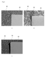
- Figures 2A, 2B, and 2C are SEM images showing observation examples of resin-rich matrices.
- FIG. 2A is an SEM image showing an example in which no resin-rich matrix is observed on the side surface of the silicon chip.
- FIG. 2B is an SEM image showing an example in which a resin-rich matrix with a maximum thickness of less than 2 ⁇ m was observed on the side surface of the silicon chip.
- FIG. 2C is an SEM image showing an example in which a resin-rich matrix with a maximum thickness of 2 ⁇ m or more was observed on the side surface of the silicon chip.
- the LCM material according to this embodiment consists of an epoxy resin composition containing (A) an epoxy resin, (B) a curing accelerator, (C) a filler, and (D) an elastomer.
- the blending ratio of the (C) filler to the epoxy resin composition is 73.0% by mass or more.
- the blending ratio of (D) the elastomer to the total of the components of the LCM material excluding the (C) filler is 7.0% by mass or more.
- the inventors presume the reason as follows.
- the present inventors investigated the cause of generation of the resin-rich matrix.
- the resin-rich matrix is caused by the phenomenon (1) and the phenomenon (2) below occurring in succession.
- the present inventors have found that the compounding ratio of the curable component contained in the LCM material (the component whose volume shrinks when the LCM material is cured) is suppressed as low as possible. I considered. For this purpose, it is considered important to maximize the compounding ratio of the non-curing component (the component whose volume does not shrink during curing) consisting of a combination of (C) a filler and (D) an elastomer. . As a result of trial and error, it was found that the resin-rich matrix can be effectively suppressed when the following conditions (i) and (ii) are satisfied.
- the mixing ratio of (C) the filler to the epoxy resin composition contained in the LCM material is 73.0% by mass or more.
- the blending ratio of (D) elastomer to the total of components excluding (C) filler from the epoxy resin composition contained in the LCM material is 7.0% by mass or more.
- Both (C) the filler and (D) the elastomer are non-curing components that do not cause the volume shrinkage when cured. Therefore, it is conceivable to suppress the resin-rich matrix by using a large amount of either one of the filler and the elastomer. However, in this embodiment, it is extremely important to use a combination of both so as to satisfy the above conditions (i) and (ii). First, when only a large amount of (D) elastomer is used without using (C) filler, the thickening effect resulting from the addition of (C) filler cannot be obtained at all. Therefore, a viscosity suitable for compression molding cannot be secured.
- (C) an epoxy resin composition containing no filler cannot be used as an LCM material in the first place.
- the larger the amount of (C) filler added the more (A) the LCM material of the curable component made of epoxy resin or the like. ratio in the composition is relatively small. Therefore, the volume shrinkage in the resin matrix can be made smaller when the LCM material is cured.
- the amount of volumetric shrinkage at the time of curing can only be made smaller, and the occurrence of volumetric shrinkage itself cannot be suppressed. For this reason, it is difficult to avoid the occurrence of a peeling phenomenon due to the volume shrinkage. Therefore, as a result, it is difficult to suppress the generation of the resin-rich matrix only by increasing the amount of the filler (C) added.
- the organic component (D) elastomer and the organic component (A) curable component such as epoxy resin react and bond to each other. For this reason, it is considered that the resin matrix containing the cured curable component is deformed after curing. Then, it is considered that the elastomer matrix ((D) elastomer contained in the cured LCM material) bonded to the resin matrix is also deformed along with this. That is, it is believed that during curing of the LCM material, the resin matrix deforms so that its volume shrinks more than before curing. On the other hand, the easily deformable elastomeric matrix is considered to expand and deform so as to counteract the volumetric contraction in the resin matrix.
- the elastomer matrix is present in a sufficient amount to cancel the volumetric shrinkage in the resin matrix after the LCM material is cured, the peeling phenomenon (phenomenon described in (1) above) is unlikely to occur. . And, as a result, it is thought that generation of a resin-rich matrix can also be suppressed.
- condition (i) the proportion of the resin matrix that has shrunk in volume contained in the cured product of the LCM material is a certain amount or less. For this reason, it is presumed that condition (i) contributes to more effectively exhibiting the action of canceling out the volumetric shrinkage in the resin matrix due to the addition of (D) elastomer. Moreover, it is presumed that condition (ii) contributes to securing a sufficient amount of elastomer matrix to absorb the volumetric shrinkage in the resin matrix to the extent that the occurrence of the delamination phenomenon can be suppressed.
- the (D) elastomer compounded in the LCM material is a liquid substance having a viscosity of 110 Pa ⁇ s or more at room temperature
- the elastomer molecules are converted into the (A) epoxy resin or the like when the LCM material is cured. It is believed that it is incorporated into the crosslinked structure formed by the curable component. In this case, an elastic resin matrix is formed. Therefore, even in such a case, if a sufficient amount of (D) elastomer is blended with the LCM material, the volume shrinkage in the resin matrix due to the curing reaction is canceled by the elasticity of the resin matrix itself. It is thought that It is considered that this can suppress the occurrence of the peeling phenomenon and further the occurrence of the resin-rich matrix.
- liquid compression molding material refers to a cured liquid that has a viscosity of 2000 Pa s or less at room temperature (25° C.) and that can be used in compression molding processes. means a flexible resin composition. Therefore, the viscosity at room temperature of the liquid compression molding material of the present embodiment is not particularly limited as long as it is 2000 Pa ⁇ s or less. However, the viscosity is preferably 1000 Pa ⁇ s or less, more preferably 700 Pa ⁇ s or less, and still more preferably 500 Pa ⁇ s or less from the viewpoint of workability in manufacturing the liquid compression molding material.
- the lower limit of the viscosity at room temperature is not particularly limited. However, from the viewpoint of handleability, etc., the lower limit is 50 Pa ⁇ s, more preferably 100 Pa ⁇ s.
- the viscosity range of the liquid compression molding material at 120° C. is preferably 0.5 Pa ⁇ s to 40.0 Pa ⁇ s, more preferably 0.5 Pa ⁇ s to 20.0 Pa ⁇ s, still more preferably 0.8 Pa. ⁇ s to 8.0 Pa ⁇ s.
- the viscosity at 120° C. is 0.5 Pa ⁇ s or more, it is possible to easily suppress the liquid compression molding material from flowing out of the mold when compression molding the LCM material according to the present embodiment.
- the viscosity at 120° C. is 40.0 Pa ⁇ s or less, it is possible to easily suppress filling failure of the liquid compression molding material due to the high viscosity during the compression molding. The details of the method for measuring the viscosity at room temperature and 120°C will be described later.
- the (A) epoxy resin that can be used in the LCM material according to the present embodiment is not particularly limited as long as it is a variety of epoxy resins that are generally used for semiconductor encapsulation. However, from the viewpoint of reliability (thermal cycle resistance), etc., it is preferable to use a polyfunctional type epoxy resin (an epoxy resin having two or more epoxy groups in one molecule) as the epoxy resin. Also, as the epoxy resin used for the LCM material according to this embodiment, only one type of epoxy resin may be used. Alternatively, two or more epoxy resins appropriately combined may be used. At least one epoxy group should be contained in one epoxy resin molecule. The preferred number of epoxy groups is usually 2 or more. In addition, the upper limit of the number of epoxy groups is not particularly limited.
- the upper limit of the preferable number of epoxy groups is usually 5 or less.
- the epoxy group is not particularly limited as long as it is various epoxy resins generally used for semiconductor encapsulation.
- the epoxy resin is not particularly limited as long as it is a variety of epoxy resins generally used for semiconductor encapsulation.
- a single epoxy resin can be used as a raw material for the preparation of the LCM material.
- a mixed composition obtained by blending and dispersing core-shell type rubber particles as an elastomer at a high concentration in an epoxy resin can also be used. Details of the masterbatch will be described later.
- the epoxy resin is not particularly limited as long as it is a variety of epoxy resins generally used for semiconductor encapsulation.
- the epoxy resin is not particularly limited as long as it is a variety of epoxy resins generally used for semiconductor encapsulation.
- As the epoxy resin an aliphatic epoxy resin and/or an aromatic epoxy resin can be used. Both are preferably used in combination.
- aromatic epoxy resins include bisphenol A type epoxy resins such as p-glycidyloxyphenyldimethyltrisbisphenol A diglycidyl ether; bisphenol F type epoxy resins; novolac type epoxy resins; fluorene type epoxy resins; diepoxy resins such as p-tert-butylphenyl glycidyl ether and 1,4-phenyldimethanol diglycidyl ether; 3,3′,5,5′-tetramethyl-4,4′-diglycidyloxybiphenyl; biphenyl-type epoxy resins such as; aminophenol-type epoxy resins such as diglycidylaniline, diglycidyltoluidine, triglycidyl-p-aminophenol, and tetraglycidyl-m-xylylenediamine; and naphthalene-type epoxy resins. . Epoxy resins that can be used are not limited to these.
- bisphenol F type epoxy resin bisphenol A type epoxy resin, biphenyl type epoxy resin, aminophenol type epoxy resin, and naphthalene type epoxy resin are preferably used.
- aliphatic epoxy resins examples include polytetramethylene glycol diglycidyl ether, (poly)propylene glycol diglycidyl ether, butanediol diglycidyl ether, neopentyl glycol diglycidyl ether, 1,6-hexanediol diglycidyl ether.
- trimethylolpropane diglycidyl ether trimethylolpropane diglycidyl ether, polytetramethylene ether glycol diglycidyl ether, glycerol diglycidyl ether, and neopentyl glycol diglycidyl ether; triepoxy resins; vinyl(3,4-cyclohexene)dioxide and cycloaliphatic such as 2-(3,4-epoxycyclohexyl)-5,1-spiro-(3,4-epoxycyclohexyl)-m-dioxane Epoxy resins; glycidylamine-type epoxy resins such as tetraglycidylbis(aminomethyl)cyclohexane; hydantoin-type epoxy resins such as 1,3-diglycidyl-5-methyl-5-ethylhydantoin; and 1,3-bis(3 -glycidoxypropyl)-1,1,3,
- polytetramethylene glycol diglycidyl ether polytetramethylene glycol diglycidyl ether, (poly)propylene glycol diglycidyl ether, 1,4-hexanediol diglycidyl ether, 1,4-butanediol diglycidyl ether, (poly)ethylene glycol diglycidyl ether, and pentaerythritol diglycidyl ether are suitable examples.
- the (B) curing accelerator is not particularly limited as long as it is a commonly used various curing accelerator.
- Examples of curing accelerators include nitrogen-containing heterocyclic curing accelerators such as imidazole compounds (including types adducted or microencapsulated with epoxy resins or isocyanate resins), tertiary amine curing Accelerators, and phosphorus compound-based curing accelerators.
- a nitrogen-containing heterocyclic curing accelerator is preferable from the viewpoint of reliability (thermal cycle resistance).
- Only one type of curing accelerator can be used as the curing accelerator compounded in the LCM material.
- two or more curing accelerators may be used in combination.
- the mixing ratio of the curing accelerator is not particularly limited. A preferable blending ratio is 2.0% by mass to 8.0% by mass, and a more preferable blending ratio is 2.5% by mass to 6.0% by mass, based on the total of the components of the LCM material excluding the filler. be.
- nitrogen-containing heterocyclic curing accelerators include 2-methylimidazole, 2-undecylimidazole, 2-heptadecylimidazole, 2-ethyl-4-methylimidazole, 2-phenyl imidazole, 2-phenyl-4-methylimidazole, 2-phenyl-4,5-dihydroxymethylimidazole, 2-phenyl-4-methyl-5-hydroxymethylimidazole, 1-cyanoethyl-2-undecylimidazole, 1-cyanoethyl -2-ethyl-4-imidazole, 2-phenylimidazole, 1-benzyl-2-phenylimidazole, benzimidazole, 2,4-diamino-6-[2'-methylimidazolyl-(1')]ethyl-s- Imidazole compounds such as triazine, 2-phenyl-4,5-dihydroxymethylimidazole, and 2,3
- nitrogen-containing heterocyclic curing accelerators other than imidazole compounds include diazabicycloundecene (DBU), DBU-phenol salt, DBU-octylate, DBU-p-toluenesulfonate, DBU- Formate, DBU-orthophthalate, DBU-phenol novolak resin salt, DBU tetraphenylborate salt, diazabicyclononene (DBN), DBN-phenol novolak resin salt, diazabicyclooctane, pyrazole, oxazole, thiazole, imidazoline , pyrazine, morpholine, thiazine, indole, isoindole, purine, quinoline, isoquinoline, quinoxaline, cinnoline,
- encapsulated imidazole called microcapsule imidazole or epoxy adduct imidazole can also be used. That is, an encapsulated imidazole-based latent curing agent obtained by adducting an imidazole compound with urea or an isocyanate compound and further blocking the surface with an isocyanate compound can also be used.
- an encapsulated imidazole-based latent curing agent obtained by blocking the surface of an imidazole compound adducted with an epoxy compound with an isocyanate compound can also be used.
- HX3941HP ⁇ HXA3042HP ⁇ HXA3922HP ⁇ HXA3792 ⁇ HX3748 ⁇ HX3721 ⁇ HX3722 ⁇ HX3088 ⁇ HX3741 ⁇ HX3742 ⁇ HX3613( ⁇ ) amicure PN-23J, and Amicure PN-40J (both manufactured by Ajinomoto Fine-Techno Co., Ltd., trade names), and Fujicure FXR-1121 (manufactured by T&K TOKA Co., Ltd., trade names).
- (C) Filler is added to the LCM material to reduce the linear expansion coefficient of the cured LCM material (sealing material) and to suppress volumetric shrinkage in the resin matrix caused by the curing reaction of the LCM material.
- (C) fillers include various inorganic particles including silica fillers and alumina fillers.
- a silica filler is preferable because the filling amount can be increased.
- the surface of the (C) filler may be treated with, for example, a silane coupling agent.
- the (C) filler may further have other functions such as coloring properties in addition to the functions described above.
- Examples of such (C) fillers include inorganic pigments such as white pigments.
- examples of such inorganic pigments include magnesia, titania, zirconia, boron nitride, aluminum nitride, titanium oxide, magnesium oxide, zinc oxide, diamond, potassium titanate, magnesium sulfate, sepiolite, xonolite, aluminum borate, calcium carbonate.
- titanium oxide, barium sulfate, zinc oxide, magnesium hydroxide, barium titanate, and zirconia oxide examples include magnesia, titania, zirconia, boron nitride, aluminum nitride, titanium oxide, magnesium oxide, zinc oxide, diamond, potassium titanate, magnesium sulfate, sepiolite, xonolite, aluminum borate, calcium carbonate.
- titanium oxide, barium sulfate, zinc oxide, magnesium hydroxide, barium titanate, and zirconia oxide examples of such (C) fillers.
- the average particle size of the filler is not particularly limited.
- a preferred average particle size is 0.1 ⁇ m to 15.0 ⁇ m.
- a more preferable average particle size is 0.3 ⁇ m to 10.0 ⁇ m.
- the shape of the filler is not particularly limited.
- any of spherical, amorphous, and scaly fillers can be used.
- the average particle diameter of the (C) filler is the volume average particle diameter D50 (small diameter in particle size distribution It means the particle diameter) value at which the cumulative distribution rate from the side is 50%.
- a sample for measurement can be prepared by dispersing 5 mg of filler blended in 50 mg of dispersant using an ultrasonic disperser for 10 minutes. The prepared sample was measured under conditions of a flow rate of 50 ml/second, a measurement time of 90 seconds, pure water as the solvent, and a solvent refractive index of 1.333.
- the blending ratio of the filler is 73.0% by mass or more, more preferably 77.5% by mass or more, and still more preferably 79.0% by mass, based on the epoxy resin composition constituting the LCM material (100% by mass). It is at least 80.0% by mass, particularly preferably at least 80.0% by mass.
- the blending ratio of (D) the elastomer to the total of the components of the epoxy resin composition excluding the filler is 7.0% by mass or more
- the blending ratio of the (C) filler to the LCM material is 73.0% by mass. By doing so, it is possible to suppress the generation of a resin-rich matrix.
- the upper limit of the mixing ratio of (C) the filler is not particularly limited.
- the upper limit is preferably 87.5% by mass or less, or more. Preferably, it is 86.0% by mass or less.
- thermosetting elastomer any known thermosetting elastomer can be used as long as it has elasticity at least after the LCM material is cured.
- examples of elastomers include core-shell rubber particles, silicone resins, and butadiene-acrylonitrile copolymers. Among these elastomers, in addition to the effect of suppressing the generation of a resin-rich matrix, it is possible to impart injectability to LCM materials, suppress peeling of LCM materials (sealing materials) from electronic devices after curing, and prevent migration. From the viewpoint of suppression, core-shell type rubber particles are preferably used.
- the properties of the (D) elastomer before curing the LCM material are not particularly limited.
- Any substance can be used as long as it is a solid substance or a liquid substance having a viscosity of 110 Pa ⁇ s or more at room temperature. It is presumed that the liquid substance changes to a solid substance when the LCM material is cured, and that the elastomer molecules are incorporated into the crosslinked structure of the epoxy resin after curing.
- core, shell (polybutadiene resin, acrylic copolymer) because it has a low elastic modulus in the operating temperature range of the LCM material, so that the shrinkage stress during curing of the LCM material can be reduced. ) is preferably used.
- a mixed composition can also be used as the raw material used for preparing the LCM material.
- This masterbatch can be prepared by a masterbatch process of blending and dispersing core-shell type rubber particles in an epoxy resin.
- a curing agent such as an acid anhydride can also be used in combination as a component other than the core-shell type rubber particles and the epoxy resin, if necessary.
- the epoxy resin used for masterbatch processing is not particularly limited.
- a bisphenol type epoxy resin is preferably used.
- Examples of bisphenol type epoxy resins include bisphenol A type epoxy resins and bisphenol F type epoxy resins. Among these, bisphenol F type epoxy resins are more preferably used.
- the blending ratio of the elastomer is 7.0% by mass or more, preferably 7.0% by mass or more, based on the total of the components (C) excluding the filler from the epoxy resin composition constituting the LCM material (100% by mass). It is 8.0% by mass or more, more preferably 11.0% by mass or more.
- the blending ratio of the (C) filler to the epoxy resin composition is 73.0% by mass or more, and the blending ratio of the (D) elastomer is 7.0% by mass or more, the resin-rich matrix can be suppressed.
- the upper limit of the mixing ratio of (D) the elastomer is not particularly limited. From the viewpoint of suppressing volumetric shrinkage in the resin matrix during curing of the LCM material and improving workability in adjusting the LCM material, the upper limit is preferably 16.5% by mass or less, more preferably 15% by mass. 0% by mass or less.
- the LCM material of the present embodiment may optionally contain other components other than components A to D and the solvent. No solvent is used in the LCM material of this embodiment. Other components are not particularly limited.
- a curing agent can be preferably used.
- components ((F) other additives) other than (E) the curing agent include coupling agents, ion trapping agents, leveling agents, antioxidants, antifoaming agents, flame retardants, colorants ( provided, however, that (C) inorganic pigments that also function as fillers are excluded), and reactive diluents.
- the type and blending amount of other additives can be determined according to a conventional method.
- the total content of (F) other additives contained in the LCM material of the present embodiment is generally more than 0% by mass and 3.5% by mass or less. .
- the (E) curing agent is not particularly limited as long as it is a commonly used various curing agent.
- curing agents that can be used include amine-based curing agents, acid anhydride-based curing agents, and phenol-based curing agents.
- the blending amount of the curing agent is preferably determined so that the stoichiometric equivalent ratio (curing agent equivalent/epoxy group equivalent) to the epoxy resin is 0.01 to 1.00. A more preferable equivalent ratio is 0.01 to 0.50. A more preferable equivalent ratio is 0.08 to 0.30.
- amine curing agents include aliphatic polyamines such as triethylenetetramine, tetraethylenepentamine, m-xylenediamine, trimethylhexamethylenediamine, and 2-methylpentamethylenediamine, isophorone diamine, 1, Alicyclic polyamines such as 3-bisaminomethylcyclohexane, bis(4-aminocyclohexyl)methane, norbornenediamine, and 1,2-diaminocyclohexane, N-aminoethylpiperazine, and 1,4-bis(2-amino -2-methylpropyl)piperazine, as well as piperazine-type polyamines such as diethyltoluenediamine, dimethylthiotoluenediamine, 4,4′-diamino-3,3′-diethyldiphenylmethane, bis(methylthio)toluenediamine, diaminodiphenylmethane.
- m-phenylenediamine diaminodiphenylsulfone, diethyltoluenediamine, trimethylenebis(4-aminobenzoate), and polytetramethyleneoxide-di-p-aminobenzoate.
- Examples of commercially available products include Epicure-W and Epicure-Z (trade name of Yuka Shell Epoxy Co., Ltd.), jER Cure (registered trademark)-W, and jER Cure (registered trademark)-Z (Mitsubishi Chemical Corporation Company, trade name), Kayahard AA, Kayahard AB, and Kayahard AS (Nippon Kayaku Co., Ltd., trade name), Thothamine HM-205 (Nippon Steel & Sumikin Chemical Co., Ltd., trade name), Adeka Hardener EH-101 (ADEKA Co., Ltd., trade name), Epomic Q-640, Epomic Q-643 (Mitsui Chemicals, trade name), DETDA80 (Lonza, trade name), and Thothamine HM-205 (Nippon Steel & Sumikin Chemical Co., Ltd., trade name).
- acid anhydride curing agents include alkylated tetrahydrophthalic anhydrides such as methyltetrahydrophthalic anhydride, methylhexahydrophthalic anhydride, and methyltetrahydrophthalic anhydride, hexahydrophthalic anhydride , methylhymic anhydride, alkenyl-substituted succinic anhydride, methyl nadic anhydride, and glutaric anhydride.
- alkylated tetrahydrophthalic anhydrides such as methyltetrahydrophthalic anhydride, methylhexahydrophthalic anhydride, and methyltetrahydrophthalic anhydride, hexahydrophthalic anhydride , methylhymic anhydride, alkenyl-substituted succinic anhydride, methyl nadic anhydride, and glutaric anhydride.
- phenolic curing agents include monomers, oligomers, and polymers having phenolic hydroxyl groups. More specific examples include phenol novolac resins, alkylated and allylated products thereof, cresol novolak resins, phenol aralkyl (including phenylene and biphenylene skeletons) resins, naphthol aralkyl resins, triphenolmethane resins, and dicyclopentadiene type phenol resins. are mentioned.
- the LCM material of this embodiment is prepared by mixing and agitating each component as a raw material.
- the method of mixing and stirring is not particularly limited. A known method can be used. For example, a roll mill can be used.
- the (A) epoxy resin used as a raw material is solid, the (A) epoxy resin is liquefied by, for example, heat treatment before mixing with other components.
- all the raw materials can be mixed at once.
- the rest of the ingredients may be mixed with a primary mixture prepared by mixing some ingredients selected from all the ingredients as raw materials. For example, if it is difficult to uniformly disperse (A) the epoxy resin and (C) the filler, for the primary mixture prepared by mixing the (A) epoxy resin and (C) the filler, and the remaining ingredients may be mixed.
- the LCM material of this embodiment can be widely applied to resin sealing of various electronic components such as semiconductor elements or LED packages.
- the LCM material of the present embodiment can be used for resin sealing of electronic components by compression molding.
- compression molding the inside of a mold is filled in advance with a liquid epoxy resin composition (LCM material).
- a member to be resin-sealed is placed in the mold. Press mold clamping is then performed.
- compression molding does not require flow paths (gates, runners, etc.) for supplying resin.
- compression molding is characterized by a usage efficiency of the epoxy resin composition that is close to 100%.
- An electronic component manufactured using the LCM material of the present embodiment comprises a cured product of the LCM material of the present embodiment.
- the electronic member also includes an electronic element such as a semiconductor element or a light-emitting element, or a substrate, depending on the type of electronic component.
- the electronic component is a semiconductor device
- the semiconductor device includes a substrate, a semiconductor element arranged on the substrate, and the LCM material of the present embodiment that seals the gap between the semiconductor element and the substrate. and at least a cured product of
- Such a semiconductor device can be manufactured by a compression molding method, a step of filling the gap between the substrate and the semiconductor element arranged on the substrate with the LCM material of the present embodiment, and then clamping the LCM material.
- the LCM material of the present embodiment is a material normally used for manufacturing various electronic components using compression molding. However, if necessary, it can also be used for manufacturing various electronic components using molding methods other than compression molding. [Example]
- Curing accelerator 2P4MZ (2-phenyl-4-methylimidazole, manufactured by Shikoku Chemical Industry Co., Ltd.) ⁇ 2MZA (2,4-diamino-6-[2′-methylimidazolyl-(1′)]-ethyl-s-triazine, manufactured by Shikoku Chemical Industry Co., Ltd.) ⁇ 2P4MHZ (imidazole compound, manufactured by Shikoku Kasei Kogyo Co., Ltd.)
- Elastomer KMP605 silicone composite powder, manufactured by Shin-Etsu Chemical Co., Ltd., elastomer component 100% by mass
- CTBN1008SP carboxyl group-terminated butadiene-acrylonitrile copolymer, manufactured by Chori GLEX, elastomer component 100% by mass
- KMP605 is a solid elastomer
- CTBN1008SP is a liquid elastomer with a viscosity of 110 to 160 Pa ⁇ s at room temperature.
- Masterbatch (mixed composition of (A) component and (D) component) ⁇ MX-137 (core-shell type butadiene rubber particles, manufactured by Kaneka Corporation, elastomer component 33% by mass + epoxy resin component 67% by mass) ⁇ MX-965 (core-shell type silicone rubber particles, manufactured by Kaneka Corporation, elastomer component 25% by mass + epoxy resin component 75% by mass) *1
- the masterbatch is listed in the column of (D) elastomer in Tables 1 to 3. *2 Core-shell type butadiene rubber particles and core-shell type silicone rubber particles are solid elastomers.
- a silicon wafer 10 (diameter of 12 inches, thickness of 760 ⁇ m) was prepared as a member to be resin-sealed (a member to be resin-sealed).
- silicon chips 20 (length: 18 mm, width: 18 mm, height: 300 ⁇ m) are arranged on the upper surface of the silicon wafer 10 .
- the silicon chips 20 were arranged along the periphery of the silicon wafer 10 at regular intervals (every 90 degrees) in the circumferential direction. Between the silicon wafer 10 and the silicon chip 20, as shown on the right side of FIG.
- a sealing layer 40 (cured layer of LCM material) having a thickness of 500 ⁇ m was formed on the molded product thus obtained, which resin-sealed the silicon chips 20 arranged on the silicon wafer 10 .
- a resin-rich matrix with a maximum thickness of less than 2 ⁇ m was observed on the side surface of the silicon chip 20 .
- C As illustrated in FIG. 2C, a resin-rich matrix with a maximum thickness of 2 ⁇ m or more was observed on the side surface of the silicon chip 20 .
- Viscosity (viscosity at 25°C) The 25° C. viscosity was measured using a Brookfield HB-DV viscometer (model number: HB-DV1) at a liquid temperature of 25° C. and 10 rpm for the LCM material immediately after preparation.
- the evaluation criteria for the "25° C. viscosity determination" shown in the table are as follows. A: Viscosity at 25°C is less than 1000 Pa s B: Viscosity at 25°C is 1000 Pa s or more
- silicon wafer 10 silicon wafer 20 silicon chip 30 spacer 40 sealing layer 50 resin rich matrix
Abstract
(A)エポキシ樹脂と、(B)硬化促進剤と、(C)フィラーと、(D)エラストマーとを含むエポキシ樹脂組成物からなり、前記エポキシ樹脂組成物に対する前記(C)フィラーの配合割合が、73.0質量%以上であり、前記エポキシ樹脂組成物から前記(C)フィラーを除いた成分の合計に対する前記(D)エラストマーの配合割合が、7.0質量%以上である液状コンプレッションモールド材が提供される。
Description
本開示は、液状コンプレッションモールド材、電子部品、半導体装置、および半導体装置の製造方法に関する。
半導体装置を構成する集積回路等の半導体素子の多くは、封止材で封止されている。半導体素子の封止を行うための成形方法は複数存在する。近年、相対的に大型の成形品の製造により適している圧縮成形が半導体素子の封止に採用される機会が、増加している。これは、ウェハーレベルチップサイズパッケージ技術の普及が進んでいることなどに起因する。この技術は、回路形成完了後の、チップに切り分けられていないウェハーを、そのまま封止することを伴うことを特徴とする。
一般的に、圧縮成形による半導体素子の封止には、主に、顆粒状等の固形の樹脂組成物が用いられる。しかし最近では、新たな圧縮成形技術の開発に伴い、液状の硬化性樹脂組成物(いわゆる液状コンプレッションモールド材)が用いられることも多くなっている。以下、液状コンプレッションモールド材を「LCM(Luquid Compression molding)材」と略称する場合がある。
LCM材としては、例えば、電気特性、耐湿性、耐熱性、機械特性、および接着性の諸特性をバランスよく確保する観点から、液状のエポキシ樹脂組成物がしばしば用いられる。このようなLCM材としては、たとえば、特許文献1、2に記載の液状のエポキシ樹脂組成物が提案されている。このLCM材は、主要な成分として、そのLCM材の硬化時に樹脂マトリックスを形成する樹脂マトリックス前駆体成分(エポキシ樹脂、硬化剤等)と、多量のフィラーと、を含む。すなわち、前記硬化後において、樹脂マトリックスは、硬化した樹脂マトリックス前駆体成分を含む。
一方、従来のLCM材を用いて圧縮成形を実施した場合、半導体素子等の電子素子の側面近傍を覆う封止材(LCM材の硬化物)が、フィラーを殆ど含まない樹脂マトリックス(以下、「レジンリッチマトリックス」と称する)のみから構成される現象が発生してしまうことがある。封止材中においてレジンリッチマトリックスが形成された場合、半導体装置などの電子装置の信頼性の点で問題が生じる。
本実施形態に係る液状コンプレッションモールド材は、上記事情に鑑みて実現された。すなわち、本実施形態は、圧縮成形により液状コンプレッションモールド材を硬化させて得られる封止材中でのレジンリッチマトリックスの発生を抑制できる液状コンプレッションモールド材を提供することを課題とする。また、本実施形態は、この液状コンプレッションモールド材を用いた電子部品および半導体装置を提供することを課題とする。さらに、本実施形態は、この液状コンプレッションモールド材を用いた半導体装置の製造方法を提供することを課題とする。
上記課題は、以下に説明される本実施形態により達成される。
すなわち、本開示の実施形態の一に係る液状コンプレッションモールド材は、(A)エポキシ樹脂と、(B)硬化促進剤と、(C)フィラーと、(D)エラストマーとを含むエポキシ樹脂組成物からなり、前記エポキシ樹脂組成物に対する前記(C)フィラーの配合割合が、73.0質量%以上であり、前記エポキシ樹脂組成物から前記(C)フィラーを除いた成分の合計に対する前記(D)エラストマーの配合割合が、7.0質量%以上である。
すなわち、本開示の実施形態の一に係る液状コンプレッションモールド材は、(A)エポキシ樹脂と、(B)硬化促進剤と、(C)フィラーと、(D)エラストマーとを含むエポキシ樹脂組成物からなり、前記エポキシ樹脂組成物に対する前記(C)フィラーの配合割合が、73.0質量%以上であり、前記エポキシ樹脂組成物から前記(C)フィラーを除いた成分の合計に対する前記(D)エラストマーの配合割合が、7.0質量%以上である。
本開示の他の実施形態に係る液状コンプレッションモールド材では、好ましくは前記(D)エラストマーが、固体状の物質、および、室温において粘度が110Pa・s以上の液体状の物質、からなる群より選択される少なくとも1種の物質である。
本開示の他の実施形態に係る液状コンプレッションモールド材では、好ましくは前記エポキシ樹脂組成物から前記(C)フィラーを除いた成分に対する前記(D)エラストマーの配合割合が7.0質量%~16.5質量%である。
本開示の他の実施形態に係る液状コンプレッションモールド材では、好ましくは前記エポキシ樹脂組成物に対する前記(C)フィラーの配合割合が、73.0質量%~87.5質量%である。
本開示の他の実施形態に係る液状コンプレッションモールド材では、好ましくは120℃での粘度が0.5Pa・s~40.0Pa・sである。
本開示の他の実施形態に係る液状コンプレッションモールド材では、好ましくは前記(B)硬化促進剤が含窒素複素環化合物を含む。
本開示の他の実施形態に係る液状コンプレッションモールド材では、硬化剤(E)をさらに含むことが好ましい。
本開示の他の実施形態に係る液状コンプレッションモールド材では、前記(E)硬化剤がフェノール系硬化剤、アミン系硬化剤および酸無水物系硬化剤からなる群より選択される少なくとも1種を含むことが好ましい。
本開示の他の実施形態に係る液状コンプレッションモールド材では、好ましくは前記(A)エポキシ樹脂が脂肪族エポキシ樹脂および芳香族エポキシ樹脂からなる群より選択される少なくとも1種が含まれる。
本開示の実施形態に係る電子部品は、本発明の液状コンプレッションモールド材の硬化物からなる封止材を備える。
本開示の実施形態に係る半導体装置は、基板と、前記基板上に配置された半導体素子と、前記半導体素子と前記基板との間の空隙を封止している本開示の実施形態に係る液状コンプレッションモールド材の硬化物と、を備える。
本開示の実施形態に係る半導体装置の製造方法は、圧縮成形法により、基板と、前記基板上に配置されている半導体素子との間の空隙を、本開示の実施形態に係る液状コンプレッションモールド材で充填することと、プレス型締めすることと、前記液状コンプレッションモールド材を硬化することと、を含む。
本実施形態に係る液状コンプレッションモールド材によれば、圧縮成形により硬化された液状コンプレッションモールド材を含む封止材中にレジンリッチマトリックスが発生することを抑制することができる。また、このLCM材を用いた電子部品、半導体装置、および、半導体装置の製造方法を提供することができる。
本実施形態に係るLCM材は、(A)エポキシ樹脂と、(B)硬化促進剤と、(C)フィラーと、(D)エラストマーと、を含むエポキシ樹脂組成物からなる。前記エポキシ樹脂組成物に対する(C)フィラーの配合割合が、73.0質量%以上である。また、前記LCM材から(C)フィラーを除いた成分の合計に対する(D)エラストマーの配合割合が、7.0質量%以上である。これにより、前記LCM材を用いて圧縮成形を実施した場合でも、電子素子の側面近傍を覆う封止材中におけるレジンリッチマトリックスの発生を抑制することができる。
上述した効果が得られる理由は定かではない。しかし、本発明者らは、その理由を以下のように推定している。まず、本発明者らは、レジンリッチマトリックスの発生原因について検討した。その結果、本発明者らは、レジンリッチマトリックスは、下記(1)に示す現象と下記(2)に示す現象と、が連続して起こることに起因しているのではないかと推測した。
(1)圧縮成形時に、電子素子の側面を覆うように流れ込んだLCM材が硬化収縮することにより、電子素子の側面と、硬化したLCM材あるいは硬化中のLCM材と、が剥離する(以下、「剥離現象」と称することがある)。
(2)電子素子の側面と、硬化済みあるいは硬化中のLCM材との剥離により形成された隙間に流れ込んだ、フィラーを殆ど含まない未硬化の硬化性成分が硬化する。その結果、硬化したフィラーを殆ど含まない硬化性成分がレジンリッチマトリックスを形成する。
(1)圧縮成形時に、電子素子の側面を覆うように流れ込んだLCM材が硬化収縮することにより、電子素子の側面と、硬化したLCM材あるいは硬化中のLCM材と、が剥離する(以下、「剥離現象」と称することがある)。
(2)電子素子の側面と、硬化済みあるいは硬化中のLCM材との剥離により形成された隙間に流れ込んだ、フィラーを殆ど含まない未硬化の硬化性成分が硬化する。その結果、硬化したフィラーを殆ど含まない硬化性成分がレジンリッチマトリックスを形成する。
そこで、本発明者らは、レジンリッチマトリックスの発生を抑制するためには、LCM材に含まれる硬化性成分(前記LCM材の硬化時にその体積が収縮する成分)の配合比率をできるだけ低く抑制することを検討した。そのためには、(C)フィラーと(D)エラストマーとの組み合わせからなる非硬化性成分(前記硬化時にその体積が収縮しない成分)の配合比率をできる限り大きくすることが重要であると考えられた。そして、試行錯誤の結果、下記条件(i)(ii)を満たす場合にレジンリッチマトリックスを効果的に抑制できることが見出された。
(i)LCM材に含まれるエポキシ樹脂組成物に対する(C)フィラーの配合割合が、73.0質量%以上であること。
(ii)LCM材に含まれるエポキシ樹脂組成物から(C)フィラーを除いた成分の合計に対する(D)エラストマーの配合割合が、7.0質量%以上であること。
(i)LCM材に含まれるエポキシ樹脂組成物に対する(C)フィラーの配合割合が、73.0質量%以上であること。
(ii)LCM材に含まれるエポキシ樹脂組成物から(C)フィラーを除いた成分の合計に対する(D)エラストマーの配合割合が、7.0質量%以上であること。
なお、(C)フィラーおよび(D)エラストマーは、いずれも前記硬化時に前記体積収縮を伴わない非硬化性成分である。そのため、フィラーおよびエラストマーのうちのいずれか一方の成分のみを多量に用いることでレジンリッチマトリックスを抑制することも考えられる。しかしながら、本実施形態では、上記条件(i)および(ii)を満たすように、両者を組み合わせて用いることが極めて重要である。まず、(C)フィラーを用いずに多量の(D)エラストマーのみを用いる場合では、(C)フィラーの添加に起因する増粘効果が全く得られなくなる。そのため、圧縮成形に適した粘度が確保できない。すなわち、(C)フィラーを全く含まないエポキシ樹脂組成物は、そもそもLCM材として利用することができない。これに対して、(D)エラストマーを用いずに多量の(C)フィラーのみを用いる場合では、(C)フィラーの添加量が多い程、(A)エポキシ樹脂等からなる硬化性成分のLCM材の組成における割合が相対的に小さくなる。そのため、LCM材硬化時の、樹脂マトリックスにおける前記体積収縮をより小さくすることができる。しかしながら、(C)フィラーの添加量を増やすことのみでは、前記硬化時の前記体積収縮量をより小さくできるに過ぎず、前記体積収縮の発生自体は抑制できない。このため、前記体積収縮に起因する剥離現象の発生は避け難い。よって、結果的に、(C)フィラーの添加量を増やすだけでは、レジンリッチマトリックスの発生を抑制することは困難である。
一方、硬化時には、有機成分である(D)エラストマーと、有機成分である(A)エポキシ樹脂等の硬化性成分とが反応して互いに結合する。このことで、硬化後において、硬化した硬化性成分を含む樹脂マトリックスが変形していると考えられる。すると、これに伴い樹脂マトリックスと接合したエラストマーマトリックス(LCM材の硬化物中に含まれる(D)エラストマー)も変形していると考えられる。すなわち、LCM材の硬化時に、樹脂マトリックスは、硬化前よりもその体積が収縮するように変形すると考えられる。一方、変形容易なエラストマーマトリックスは、前記樹脂マトリックスにおける体積収縮を打ち消すように、膨張変形すると考えられる。したがって、LCM材の硬化後において、前記樹脂マトリックスにおける体積収縮を打ち消すのに十分な量のエラストマーマトリックスが存在していれば、剥離現象(上記(1)に示す現象)が発生しにくいと考えられる。そして、結果的に、レジンリッチマトリックスの発生も抑制できると考えられる。
ここで、条件(i)によれば、LCM材の硬化物中に含まれる体積の収縮した樹脂マトリックスの割合が一定量以下である。このことで、条件(i)は、(D)エラストマー添加による樹脂マトリックスにおける体積収縮を打ち消す作用がより効果的に発揮されることに寄与していると推定される。また、条件(ii)は、前記剥離現象の発生を抑制できる程度にまで、樹脂マトリックスにおける体積収縮を吸収できるのに十分な量のエラストマーマトリックスを確保することに寄与していると推定される。
なお、LCM材に配合される(D)エラストマーが、室温において、110Pa・s以上の粘度を有する液状物質である場合には、LCM材の硬化時に、エラストマー分子が、(A)エポキシ樹脂等の硬化性成分により形成されている架橋構造に取り込まれると考えられる。この場合、弾性を有する樹脂マトリックスが形成される。したがって、このような場合であっても、LCM材に対して十分な量の(D)エラストマーが配合されていれば、硬化反応に伴う樹脂マトリックスにおける体積収縮が、樹脂マトリックス自身が有する弾性により打ち消されると考えられる。このことで、前記剥離現象の発生、さらには、レジンリッチマトリックスの発生も抑制できると考えられる。
なお、本開示において、「液状コンプレッションモールド材(LCM材)」とは、室温(25℃)において、2000Pa・s以下の粘度を有し、かつ、圧縮成形プロセスに使用することのできる液状の硬化性樹脂組成物を意味する。したがって、本実施形態の液状コンプレッションモールド材の室温における粘度は、2000Pa・s以下であれば特に限定されない。ただし、液状コンプレッションモールド材を製造する際の作業性等の観点から、前記粘度は、好ましくは1000Pa・s以下、より好ましくは700Pa・s以下、さらに好ましくは500Pa・s以下である。なお、室温における粘度の下限値は、特に限定されない。ただし、取り扱い性等の観点からは、前記下限値は、50Pa・s、より好ましくは100Pa・sである。
また、液状コンプレッションモールド材の120℃における粘度の範囲は、好ましくは0.5Pa・s~40.0Pa・s、より好ましくは0.5Pa・s~20.0Pa・s、さらに好ましくは0.8Pa・s~8.0Pa・sである。120℃における粘度が0.5Pa・s以上であることにより、本実施形態に係るLCM材を圧縮成形する際に、金型から液状コンプレッションモールド材が流出することを容易に抑制することができる。また、120℃における粘度が40.0Pa・s以下であることにより、前記圧縮成形時に、高粘性に起因する液状コンプレッションモールド材の充填不良を、容易に抑制することができる。なお、室温および120℃における粘度の測定方法の詳細については、後述する。
次に、本実施形態に係る液状コンプレッションモールド材に含まれる各種成分の詳細について、以下に説明する。
(A)エポキシ樹脂
本実施形態に係るLCM材に用いることのできる(A)エポキシ樹脂は、一般的に半導体封止用として使用される各種のエポキシ樹脂であれば特に制限されない。しかしながら、信頼性(耐サーマルサイクル性)などの観点からは、エポキシ樹脂として、好ましくは、特に多官能タイプのエポキシ樹脂(1分子中に2個以上のエポキシ基を有するエポキシ樹脂)用いられる。また、本実施形態に係るLCM材に用いられるエポキシ樹脂としては、1種類のエポキシ樹脂のみが使用されてもよい。あるいは、適宜組み合わされた2種類以上エポキシ樹脂が用いられてもよい。エポキシ樹脂1分子には、少なくとも1個のエポキシ基が含まれていればよい。好ましいエポキシ基の数は、通常は、2以上である。なお、エポキシ基の数の上限値は、特に限定されない。好ましいエポキシ基の数の上限は、通常は、5個以下である。エポキシ基は、一般的に半導体封止用として使用される各種のエポキシ樹脂であれば、特に限定されない。エポキシ樹脂は、一般的に半導体封止用として使用される各種のエポキシ樹脂であればよく、特に限定されない。
本実施形態に係るLCM材に用いることのできる(A)エポキシ樹脂は、一般的に半導体封止用として使用される各種のエポキシ樹脂であれば特に制限されない。しかしながら、信頼性(耐サーマルサイクル性)などの観点からは、エポキシ樹脂として、好ましくは、特に多官能タイプのエポキシ樹脂(1分子中に2個以上のエポキシ基を有するエポキシ樹脂)用いられる。また、本実施形態に係るLCM材に用いられるエポキシ樹脂としては、1種類のエポキシ樹脂のみが使用されてもよい。あるいは、適宜組み合わされた2種類以上エポキシ樹脂が用いられてもよい。エポキシ樹脂1分子には、少なくとも1個のエポキシ基が含まれていればよい。好ましいエポキシ基の数は、通常は、2以上である。なお、エポキシ基の数の上限値は、特に限定されない。好ましいエポキシ基の数の上限は、通常は、5個以下である。エポキシ基は、一般的に半導体封止用として使用される各種のエポキシ樹脂であれば、特に限定されない。エポキシ樹脂は、一般的に半導体封止用として使用される各種のエポキシ樹脂であればよく、特に限定されない。
また、LCM材の調製には、原料として単体のエポキシ樹脂を用いることができる。ただし、それ以外にも、エポキシ樹脂に、エラストマーとしてのコアシェル型ゴム粒子を高濃度で配合・分散させることにより得られる混合組成物(マスターバッチ)を用いることもできる。なお、マスターバッチの詳細については、後述する。
(A)エポキシ樹脂は、一般的に半導体封止用として使用される各種のエポキシ樹脂であれば、特に限定されない。(A)エポキシ樹脂は、一般的に半導体封止用として使用される各種のエポキシ樹脂であればよく、特に限定されない。
(A)エポキシ樹脂としては、脂肪族エポキシ樹脂および/または芳香族エポキシ樹脂を用いることができる。好適には、両者が組み合わせて用いられる。芳香族エポキシ樹脂の例としては、p-グリシジルオキシフェニルジメチルトリスビスフェノールAジグリシジルエーテルのようなビスフェノールA型エポキシ樹脂;ビスフェノールF型エポキシ樹脂;ノボラック型エポキシ樹脂;フルオレン型エポキシ樹脂;ビフェニルアラルキルエポキシ樹脂;p-tert-ブチルフェニルグリシジルエーテル、および1,4-フェニルジメタノールジグリシジルエーテルのようなジエポキシ樹脂;3,3’,5,5’-テトラメチル-4,4’-ジグリシジルオキシビフェニルのようなビフェニル型エポキシ樹脂;ジグリシジルアニリン、ジグリシジルトルイジン、トリグリシジル-p-アミノフェノール、およびテトラグリシジル-m-キシリレンジアミンのようなアミノフェノール型エポキシ樹脂;並びに、ナフタレン型エポキシ樹脂が挙げられる。使用することのできるエポキシ樹脂は、これらに限定されるものではない。
(A)エポキシ樹脂としては、脂肪族エポキシ樹脂および/または芳香族エポキシ樹脂を用いることができる。好適には、両者が組み合わせて用いられる。芳香族エポキシ樹脂の例としては、p-グリシジルオキシフェニルジメチルトリスビスフェノールAジグリシジルエーテルのようなビスフェノールA型エポキシ樹脂;ビスフェノールF型エポキシ樹脂;ノボラック型エポキシ樹脂;フルオレン型エポキシ樹脂;ビフェニルアラルキルエポキシ樹脂;p-tert-ブチルフェニルグリシジルエーテル、および1,4-フェニルジメタノールジグリシジルエーテルのようなジエポキシ樹脂;3,3’,5,5’-テトラメチル-4,4’-ジグリシジルオキシビフェニルのようなビフェニル型エポキシ樹脂;ジグリシジルアニリン、ジグリシジルトルイジン、トリグリシジル-p-アミノフェノール、およびテトラグリシジル-m-キシリレンジアミンのようなアミノフェノール型エポキシ樹脂;並びに、ナフタレン型エポキシ樹脂が挙げられる。使用することのできるエポキシ樹脂は、これらに限定されるものではない。
これらの中でも、ビスフェノールF型エポキシ樹脂、ビスフェノールA型エポキシ樹脂、ビフェニル型エポキシ樹脂、アミノフェノール型エポキシ樹脂、および、ナフタレン型エポキシ樹脂が好適に用いられる。
また、脂肪族エポキシ樹脂の例としては、ポリテトラメチレングリコールジグリシジルエーテル、(ポリ)プロピレングリコールジグリシジルエーテル、ブタンジオールジグリシジルエーテル、ネオペンチルグリコールジグリシジルエーテル、1,6-ヘキサンジオールジグリシジルエーテル、トリメチロールプロパンジグリシジルエーテル、ポリテトラメチレンエーテルグリコールジグリシジルエーテル、グリセリンジグリシジルエーテル、およびネオペンチルグリコールジグリシジルエーテルのようなジエポキシ樹脂;トリメチロールプロパントリグリシジルエーテル、およびグリセリントリグリシジルエーテルのようなトリエポキシ樹脂;ビニル(3,4-シクロヘキセン)ジオキシド、および2-(3,4-エポキシシクロヘキシル)-5,1-スピロ-(3,4-エポキシシクロヘキシル)-m-ジオキサンのような脂環式エポキシ樹脂;テトラグリシジルビス(アミノメチル)シクロヘキサンのようなグリシジルアミン型エポキシ樹脂;1,3-ジグリシジル-5-メチル-5-エチルヒダントインのようなヒダントイン型エポキシ樹脂;並びに1,3-ビス(3-グリシドキシプロピル)-1,1,3,3-テトラメチルジシロキサンのようなシリコーン骨格を有するエポキシ樹脂が挙げられる。
これらの中でも、ポリテトラメチレングリコールジグリシジルエーテル、(ポリ)プロピレングリコールジグリシジルエーテル、1,4-ヘキサンジオールジグリシジルエーテル、1,4-ブタンジオールジグリシジルエーテル、(ポリ)エチレングリコールジグリシジルエーテル、およびペンタエリスリトールジグリシジルエーテルが好適な例である。
(B)硬化促進剤
(B)硬化促進剤としては、一般的に使用される各種の硬化促進剤であれば、特に限定されない。(B)硬化促進剤の例としては、イミダゾール化合物のような含窒素複素環系硬化促進剤(エポキシ樹脂若しくはイソシアネート樹脂とアダクト化又はマイクロカプセル化されたタイプを含む)、第三級アミン系硬化促進剤、およびリン化合物系硬化促進剤が挙げられる。特に、含窒素複素環系硬化促進剤が信頼性(耐サーマルサイクル性)の観点から好ましい。LCM材に配合される硬化促進剤として、1種類の硬化促進剤のみを用いることができる。あるいは、2種以上の硬化促進剤を併用してもよい。硬化促進剤の配合割合は、特に制限はない。好ましい配合割合は、LCM材からフィラーを除いた成分の合計に対し、2.0質量%~8.0質量%であり、より好ましい配合割合は、2.5質量%~6.0質量%である。
(B)硬化促進剤としては、一般的に使用される各種の硬化促進剤であれば、特に限定されない。(B)硬化促進剤の例としては、イミダゾール化合物のような含窒素複素環系硬化促進剤(エポキシ樹脂若しくはイソシアネート樹脂とアダクト化又はマイクロカプセル化されたタイプを含む)、第三級アミン系硬化促進剤、およびリン化合物系硬化促進剤が挙げられる。特に、含窒素複素環系硬化促進剤が信頼性(耐サーマルサイクル性)の観点から好ましい。LCM材に配合される硬化促進剤として、1種類の硬化促進剤のみを用いることができる。あるいは、2種以上の硬化促進剤を併用してもよい。硬化促進剤の配合割合は、特に制限はない。好ましい配合割合は、LCM材からフィラーを除いた成分の合計に対し、2.0質量%~8.0質量%であり、より好ましい配合割合は、2.5質量%~6.0質量%である。
含窒素複素環系硬化促進剤(含窒素複素環化合物)の具体例としては、2-メチルイミダゾール、2-ウンデシルイミダゾール、2-ヘプタデシルイミダゾール、2-エチル-4-メチルイミダゾール、2-フェニルイミダゾール、2-フェニル-4-メチルイミダゾール、2-フェニル-4,5-ジヒドロキシメチルイミダゾール、2-フェニル-4-メチル-5-ヒドロキシメチルイミダゾール、1-シアノエチル-2-ウンデシルイミダゾール、1-シアノエチル-2-エチル-4-イミダゾール、2-フェニルイミダゾール、1-ベンジル-2-フェニルイミダゾール、ベンゾイミダゾール、2,4-ジアミノ-6-〔2’-メチルイミダゾリル-(1’)]エチル-s-トリアジン、2-フェニル-4,5-ジヒドロキシメチルイミダゾール、および2,3-ジヒドロ-1H-ピロロ[1,2-a]ベンゾイミダゾールのようなイミダゾール化合物が挙げられる。より具体的な例として、2MZ、2P4MZ、および2E4MZ(いずれも四国化成工業社製、商品名)が挙げられる。また、イミダゾール化合物以外の含窒素複素環系硬化促進剤の例としては、ジアザビシクロウンデセン(DBU)、DBU-フェノール塩、DBU-オクチル酸塩、DBU-p-トルエンスルホン酸塩、DBU-ギ酸塩、DBU-オルソフタル酸塩、DBU-フェノールノボラック樹脂塩、DBU系テトラフェニルボレート塩、ジアザビシクロノネン(DBN)、DBN-フェノールノボラック樹脂塩、ジアザビシクロオクタン、ピラゾール、オキサゾール、チアゾール、イミダゾリン、ピラジン、モルホリン、チアジン、インドール、イソインドール、プリン、キノリン、イソキノリン、キノキサリン、シンノリン、およびプテリジンを挙げることができる。
また、イミダゾール化合物としては、マイクロカプセル型イミダゾールあるいはエポキシアダクト型イミダゾールと呼ばれるカプセル化イミダゾールも用いることができる。すなわち、イミダゾール化合物を尿素あるいはイソシアネート化合物でアダクトし、さらにその表面をイソシアネート化合物でブロックすることにより得られる、カプセル化したイミダゾール系潜在性硬化剤を用いることもできる。あるいは、エポキシ化合物でアダクトされているイミダゾール化合物の表面をイソシアネート化合物でブロックすることにより得られる、カプセル化したイミダゾール系潜在性硬化剤も用いることができる。具体的な例として、ノバキュアHX3941HP、ノバキュアHXA3042HP、ノバキュアHXA3922HP、ノバキュアHXA3792、ノバキュアHX3748、ノバキュアHX3721、ノバキュアHX3722、ノバキュアHX3088、ノバキュアHX3741、ノバキュアHX3742、およびノバキュアHX3613(いずれも旭化成ケミカルズ社製、商品名)、アミキュアPN-23J、およびアミキュアPN-40J(いずれも味の素ファインテクノ株式会社製、商品名)、並びにフジキュアFXR-1121(T&K TOKA株式会社製、商品名)を挙げることができる。
(C)フィラー
(C)フィラーは、LCM材に添加することによりLCM材の硬化物(封止材)の線膨張係数を下げるとともに、LCM材の硬化反応に起因する樹脂マトリックスにおける体積収縮を抑制する機能を有する物質であれば、特に限定されない。(C)フィラーの具体例としは、シリカフィラーおよびアルミナフィラーを含めた各種の無機粒子が挙げられる。特に、シリカフィラーが、充填量を高くできることから好ましい。また、(C)フィラーの表面は、例えばシランカップリング剤で処理されていてもよい。なお、(C)フィラーは、上述した機能の他に、着色性などの他の機能をさらに有してもよい。このような(C)フィラーの例として、白色顔料のような無機顔料を挙げることもできる。このような無機顔料の例としては、マグネシア、チタニア、ジルコニア、窒化ホウ素、窒化アルミ、酸化チタン、酸化マグネシウム、酸化亜鉛、ダイヤモンド、チタン酸カリウム、硫酸マグネシウム、セピオライト、ゾノライト、ホウ酸アルミニウム、炭酸カルシウム、酸化チタン、硫酸バリウム、酸化亜鉛、水酸化マグネシウム、チタン酸バリウム、および酸化ジルコニアを挙げることができる。
(C)フィラーは、LCM材に添加することによりLCM材の硬化物(封止材)の線膨張係数を下げるとともに、LCM材の硬化反応に起因する樹脂マトリックスにおける体積収縮を抑制する機能を有する物質であれば、特に限定されない。(C)フィラーの具体例としは、シリカフィラーおよびアルミナフィラーを含めた各種の無機粒子が挙げられる。特に、シリカフィラーが、充填量を高くできることから好ましい。また、(C)フィラーの表面は、例えばシランカップリング剤で処理されていてもよい。なお、(C)フィラーは、上述した機能の他に、着色性などの他の機能をさらに有してもよい。このような(C)フィラーの例として、白色顔料のような無機顔料を挙げることもできる。このような無機顔料の例としては、マグネシア、チタニア、ジルコニア、窒化ホウ素、窒化アルミ、酸化チタン、酸化マグネシウム、酸化亜鉛、ダイヤモンド、チタン酸カリウム、硫酸マグネシウム、セピオライト、ゾノライト、ホウ酸アルミニウム、炭酸カルシウム、酸化チタン、硫酸バリウム、酸化亜鉛、水酸化マグネシウム、チタン酸バリウム、および酸化ジルコニアを挙げることができる。
(C)フィラーの平均粒径は、特に制限されない。好ましい平均粒子径は、0.1μm~15.0μmである。より好ましい平均粒子径は、0.3μm~10.0μmである。(C)フィラーの形状は特に限定されない。例えば、球状、不定形状、およびりん片状のうちのいずれの形態のフィラーをも用いることができる。なお、本実施形態において、(C)フィラーの平均粒径は、レーザー回析法粒度分布測定装置(ベックマン・コールター社製 LS13320)を用いて測定される、体積平均粒径D50(粒度分布における小径側からの累積分布率50%となる粒径)値を意味する。測定は、分散剤50mgに配合された5mgのフィラーを、超音波分散機を用いて10分間分散することにより、測定用サンプルを準備することができる。準備されたサンプルを、流速50ml/秒、測定時間90秒、溶媒に純水、および溶媒屈折率1.333の条件で測定した。
(C)フィラーの配合割合は、LCM材を構成するエポキシ樹脂組成物を基準(100質量%)として、73.0質量%以上、より好ましくは77.5質量%以上、さらに好ましくは79.0質量%以上、特に好ましくは80.0質量%以上である。エポキシ樹脂組成物からフィラーを除いた成分の合計に対する(D)エラストマーの配合割合が7.0質量%以上とした場合において、さらに、(C)フィラーのLCM材に対する配合割合を73.0質量%以上とすることにより、レジンリッチマトリックスの発生を抑制することができる。一方、(C)フィラーの配合割合の上限値は、特に制限されない。ただし、LCM材としての適正な粘度を容易に確保する観点から、あるいは、LCM材を調整する際の作業性を向上させる観点からは、前記上限値は、好ましくは87.5質量%以下、より好ましくは86.0質量%以下である。
(D)エラストマー
(D)エラストマーとしては、少なくともLCM材を硬化させた後に、弾性を有する材料であれば、いかなる公知の熱硬化性のエラストマーをも利用できる。(D)エラストマーの例として、コアシェル型ゴム粒子、シリコーン樹脂、およびブタジエンアクリロニトリル共重合体が挙げられる。これらのエラストマーの中でも、レジンリッチマトリックスの発生を抑制する効果に加えて、LCM材への注入性の付与、硬化後のLCM材(封止材)の電子装置からの剥離の抑制、およびマイグレーションの抑制の観点からは、コアシェル型ゴム粒子が好適に用いられる。なお、LCM材を硬化させる前の(D)エラストマーの性状は、特に限定されない。固体状の物質、室温において粘度が110Pa・s以上の液体状の物質であれば、いずれの物質も用いることができる。なお、液体状の物質については、LCM材の硬化時に固体状の物質に変化し、かつ、硬化後においてはそのエラストマー分子がエポキシ樹脂の架橋構造中に組み込まれていると推定される。
(D)エラストマーとしては、少なくともLCM材を硬化させた後に、弾性を有する材料であれば、いかなる公知の熱硬化性のエラストマーをも利用できる。(D)エラストマーの例として、コアシェル型ゴム粒子、シリコーン樹脂、およびブタジエンアクリロニトリル共重合体が挙げられる。これらのエラストマーの中でも、レジンリッチマトリックスの発生を抑制する効果に加えて、LCM材への注入性の付与、硬化後のLCM材(封止材)の電子装置からの剥離の抑制、およびマイグレーションの抑制の観点からは、コアシェル型ゴム粒子が好適に用いられる。なお、LCM材を硬化させる前の(D)エラストマーの性状は、特に限定されない。固体状の物質、室温において粘度が110Pa・s以上の液体状の物質であれば、いずれの物質も用いることができる。なお、液体状の物質については、LCM材の硬化時に固体状の物質に変化し、かつ、硬化後においてはそのエラストマー分子がエポキシ樹脂の架橋構造中に組み込まれていると推定される。
コアシェル型ゴム粒子を構成するコアと、当該コアを被覆するシェルと、の組み合わせの例としては、(コア、シェル)=(ポリブタジエン樹脂、アクリル共重合体)、および(シリコーン樹脂、アクリル共重合体)が挙げられる。これらの組合せの中でも、LCM材の使用温度領域内において低い弾性率を有すること、そのため、LCM材の硬化時における収縮応力を低減できることから、(コア、シェル)=(ポリブタジエン樹脂、アクリル共重合体)が好適に用いられる。
なお、(D)エラストマーとしてコアシェル型ゴム粒子を使用する場合、LCM材の調製に用いられる原料としては、混合組成物(マスターバッチ)を用いることもできる。このマスターバッチは、エポキシ樹脂にコアシェル型ゴム粒子を配合・分散させるマスターバッチ処理により、調製することができる。マスターバッチ処理に際しては、コアシェル型ゴム粒子およびエポキシ樹脂以外の他の成分として、必要に応じて、例えば、酸無水物のような硬化剤も併用することができる。
マスターバッチ処理に用いるエポキシ樹脂は、特に限定されない。ビスフェノール型エポキシ樹脂が好適に用いられる。また、ビスフェノール型エポキシ樹脂の例としては、ビスフェノールA型エポキシ樹脂、およびビスフェノールF型エポキシ樹脂が挙げられる。これらの中でも、ビスフェノールF型エポキシ樹脂が、より好適に用いられる。
(D)エラストマーの配合割合は、LCM材を構成するエポキシ樹脂組成物から(C)フィラーを除いた成分の合計を基準(100質量%)とした場合において、7.0質量%以上、好ましくは8.0質量%以上、より好ましくは11.0質量%以上である。前記エポキシ樹脂組成物に対する(C)フィラーの配合割合を73.0質量%以上とした場合において、さらに、(D)エラストマーの前記配合割合を7.0質量%以上とすることにより、レジンリッチマトリックスの発生を抑制することができる。一方、(D)エラストマーの配合割合の上限値は、特に制限されない。LCM材の硬化時の樹脂マトリックスにおける体積収縮の抑制、および、LCM材を調整する際の作業性の向上の観点からは、前記上限値は、好ましくは16.5質量%以下、より好ましくは15.0質量%以下である。
その他の成分
本実施形態のLCM材には、A~D成分および溶剤以外のその他の成分を必要に応じて適宜配合してもよい。なお、溶剤は、本実施形態のLCM材には用いられていない。その他の成分としては、特に制限されない。特に、(E)硬化剤を好適に用いることができる。また、(E)硬化剤以外のその他の成分((F)その他添加剤)の例としては、カップリング剤、イオントラップ剤、レベリング剤、酸化防止剤、消泡剤、難燃剤、着色剤(但し、(C)フィラーとしても機能する無機顔料を除く)、および反応性希釈剤が挙げられる。(F)その他添加剤の種類、配合量は、常法に従い決定することができる。なお、(F)その他添加剤をさらに用いる場合、本実施形態のLCM材に含まれる(F)その他添加剤の合計含有割合は、一般的に0質量%を超え3.5質量%以下である。
本実施形態のLCM材には、A~D成分および溶剤以外のその他の成分を必要に応じて適宜配合してもよい。なお、溶剤は、本実施形態のLCM材には用いられていない。その他の成分としては、特に制限されない。特に、(E)硬化剤を好適に用いることができる。また、(E)硬化剤以外のその他の成分((F)その他添加剤)の例としては、カップリング剤、イオントラップ剤、レベリング剤、酸化防止剤、消泡剤、難燃剤、着色剤(但し、(C)フィラーとしても機能する無機顔料を除く)、および反応性希釈剤が挙げられる。(F)その他添加剤の種類、配合量は、常法に従い決定することができる。なお、(F)その他添加剤をさらに用いる場合、本実施形態のLCM材に含まれる(F)その他添加剤の合計含有割合は、一般的に0質量%を超え3.5質量%以下である。
(E)硬化剤
(E)硬化剤は、一般的に使用される各種の硬化剤であれば、特に限定されない。用いることのできる硬化剤の例として、アミン系硬化剤、酸無水物系硬化剤、およびフェノール系硬化剤を挙げることができる。
(E)硬化剤は、一般的に使用される各種の硬化剤であれば、特に限定されない。用いることのできる硬化剤の例として、アミン系硬化剤、酸無水物系硬化剤、およびフェノール系硬化剤を挙げることができる。
(E)硬化剤の配合量は、好ましくは、エポキシ樹脂との化学量論上の当量比(硬化剤当量/エポキシ基当量)が0.01~1.00となるように、決定される。より好ましい前記当量比は、0.01~0.50である。さらに好ましい前記当量比は、0.08~0.30である。
アミン系硬化剤の具体例としては、トリエチレンテトラアミン、テトラエチレンペンタミン、m-キシレンジアミン、トリメチルヘキサメチレンジアミン、および2-メチルペンタメチレンジアミンのような脂肪族ポリアミン、イソフォロンジアミン、1,3-ビスアミノメチルシクロヘキサン、ビス(4-アミノシクロヘキシル)メタン、ノルボルネンジアミン、および1,2-ジアミノシクロヘキサンのような脂環式ポリアミン、N-アミノエチルピペラジン、および1,4-ビス(2-アミノ-2-メチルプロピル)ピペラジンのようなピペラジン型のポリアミン、並びに、ジエチルトルエンジアミン、ジメチルチオトルエンジアミン、4,4’-ジアミノ-3,3’-ジエチルジフェニルメタン、ビス(メチルチオ)トルエンジアミン、ジアミノジフェニルメタン、m-フェニレンジアミン、ジアミノジフェニルスルホン、ジエチルトルエンジアミン、トリメチレンビス(4-アミノベンゾエート)、およびポリテトラメチレンオキシド-ジ-p-アミノベンゾエートのような芳香族ポリアミンが挙げられる。また、市販品の例として、エピキュア-W、およびエピキュア-Z(油化シェルエポキシ株式会社、商品名)、jERキュア(登録商標)-W、およびjERキュア(登録商標)-Z(三菱ケミカル株式会社、商品名)、カヤハードA-A、カヤハードA-B、およびカヤハードA-S(日本化薬株式会社、商品名)、トートアミンHM-205(新日鉄住金化学株式会社、商品名)、アデカハードナーEH-101(株式会社ADEKA、商品名)、エポミックQ-640、エポミックQ-643(三井化学株式会社、商品名)、DETDA80(Lonza社、商品名)、並びにトートアミンHM-205(新日鉄住金化学株式会社、商品名)が挙げられる。
酸無水物系硬化剤の具体例としては、メチルテトラヒドロフタル酸無水物、メチルヘキサヒドロフタル酸無水物、およびメチルテトラヒドロフタル酸無水物のようなアルキル化テトラヒドロフタル酸無水物、ヘキサヒドロフタル酸無水物、メチルハイミック酸無水物、アルケニル基で置換されたコハク酸無水物、メチルナジック酸無水物、並びにグルタル酸無水物が挙げられる。
フェノール系硬化剤の具体例としては、フェノール性水酸基を有するモノマー、オリゴマー、およびポリマーが挙げられる。より具体的な例として、フェノールノボラック樹脂、そのアルキル化物およびアリル化物、クレゾールノボラック樹脂、フェノールアラルキル(フェニレン、ビフェニレン骨格を含む)樹脂、ナフトールアラルキル樹脂、トリフェノールメタン樹脂、並びにジシクロペンタジエン型フェノール樹脂が挙げられる。
本実施形態のLCM材は、原料となる各成分を混合して攪拌することにより調製される。混合攪拌の方法は特に限定されない。公知の方法を利用できる。たとえば、ロールミルを用いることができる。また、原料として用いる(A)エポキシ樹脂が固形状の場合は、他の成分と混合する前に、例えば加熱処理によって、(A)エポキシ樹脂が液状化される。また、LCM材の調製に際しては、原料となる全成分を一度に混合することができる。あるいは、原料となる全成分のうちから選択された一部の成分を混合することにより調製された一次混合物に対して、残りの成分が混合されてもよい。たとえば、(A)エポキシ樹脂に対して、(C)フィラーを均一に分散させることが困難な場合は、(A)エポキシ樹脂と(C)フィラーとを混合することにより調製された一次混合物に対して、残りの各成分が混合されてもよい。
本実施形態のLCM材は、半導体素子あるいはLEDパッケージのような各種電子部品の樹脂封止用途に広く適用できる。また、本実施形態のLCM材を用いて、圧縮成形により、電子部品の樹脂封止を行うことができる。圧縮成形では、金型内が予め液状のエポキシ樹脂組成物(LCM材)で充填される。それと共に、前記金型内に樹脂封止の対象となる部材が配置される。その後、プレス型締めが行われる。圧縮成形は、射出成形などとは異なり、樹脂供給用の流路(ゲート、ランナーなど)が不要である。この点で、圧縮成形は、エポキシ樹脂組成物の使用効率がほぼ100%に近いという特徴を有する。
本実施形態のLCM材を用いて作製された電子部品は、本実施形態のLCM材の硬化物を備える。前記電子部材は、その他に、電子部品の種類に応じて、例えば、半導体素子もしくは発光素子のような電子素子、あるいは基板を備える。たとえば、電子部品が半導体装置であれば、当該半導体装置は、基板と、基板上に配置された半導体素子と、半導体素子と基板との間の空隙を封止している本実施形態のLCM材の硬化物と、を少なくとも備える。このような半導体装置は、圧縮成形法により、基板と、基板上に配置されている半導体素子との間の空隙が本実施形態のLCM材で充填された後にプレス型締めする工程と、当該LCM材を硬化する工程と、を少なくとも経ることにより製造できる。なお、本実施形態のLCM材は、通常、圧縮成形を利用した各種の電子部品の製造に利用される材料である。ただし、必要に応じて、圧縮成形以外の成形方法を利用した各種の電子部品の製造に用いることもできる。
[実施例]
[実施例]
以下に、より具体的な本実施形態を実施例により説明するただし、本実施形態は、以下に説明する実施例のみに限定されるものではない。
1.LCM材の調製
表1~表3に示す配合比率で、ロールミルを用いて原料を混合攪拌することにより、実施例1~20および比較例1~3のLCM材を調製した。なお、原料として用いた(A)~(E)成分の詳細は以下の通りである。
表1~表3に示す配合比率で、ロールミルを用いて原料を混合攪拌することにより、実施例1~20および比較例1~3のLCM材を調製した。なお、原料として用いた(A)~(E)成分の詳細は以下の通りである。
2.LCM材の調製に用いた原料成分
(A)エポキシ樹脂
・YDF8170(ビスフェノールF型エポキシ樹脂、エポキシ当量158g/eq、日鉄ケミカル&マテリアル社製)
・jER630(アミノフェノール型エポキシ樹脂、エポキシ当量98g/eq、三菱ケミカル社製)
・エポゴーセーPT(一般グレード)(脂肪族エポキシ樹脂、エポキシ当量435g/eq、四日市合成社製)
(A)エポキシ樹脂
・YDF8170(ビスフェノールF型エポキシ樹脂、エポキシ当量158g/eq、日鉄ケミカル&マテリアル社製)
・jER630(アミノフェノール型エポキシ樹脂、エポキシ当量98g/eq、三菱ケミカル社製)
・エポゴーセーPT(一般グレード)(脂肪族エポキシ樹脂、エポキシ当量435g/eq、四日市合成社製)
(B)硬化促進剤
・2P4MZ(2-フェニル-4-メチルイミダゾール、四国化成工業社製)
・2MZA(2,4-ジアミノ-6-[2’-メチルイミダゾリル-(1’)]-エチル-s-トリアジン、四国化成工業社製)
・2P4MHZ(イミダゾール化合物、四国化成工業社製)
・2P4MZ(2-フェニル-4-メチルイミダゾール、四国化成工業社製)
・2MZA(2,4-ジアミノ-6-[2’-メチルイミダゾリル-(1’)]-エチル-s-トリアジン、四国化成工業社製)
・2P4MHZ(イミダゾール化合物、四国化成工業社製)
(C)フィラー
・SE605G-SMG(3-メタクリロキシプロピルトリメトキシシラン表面処理二酸化ケイ素、平均粒径1.8μm、アドマテックス社製)
・SE1050-SEO(3-グリシドキシプロピルトリメトキシシラン表面処理二酸化ケイ素、平均粒径0.3μm、アドマテックス社製)
・STW7010-20(表面未処理二酸化ケイ素、平均粒径10.0μm、新日鉄住金マテリアル社製)
・SE605G-SMG(3-メタクリロキシプロピルトリメトキシシラン表面処理二酸化ケイ素、平均粒径1.8μm、アドマテックス社製)
・SE1050-SEO(3-グリシドキシプロピルトリメトキシシラン表面処理二酸化ケイ素、平均粒径0.3μm、アドマテックス社製)
・STW7010-20(表面未処理二酸化ケイ素、平均粒径10.0μm、新日鉄住金マテリアル社製)
(D)エラストマー
・KMP605(シリコーン複合パウダー、信越化学工業社製、エラストマー成分100質量%)
・CTBN1008SP(カルボキシル基末端ブタジエン・アクリロニトリル共重合体、蝶理GLEX社製、エラストマー成分100質量%)
※KMP605は、固体状のエラストマーであり、CTBN1008SPは、室温において粘度が110~160Pa・sである液体状のエラストマーである。
・KMP605(シリコーン複合パウダー、信越化学工業社製、エラストマー成分100質量%)
・CTBN1008SP(カルボキシル基末端ブタジエン・アクリロニトリル共重合体、蝶理GLEX社製、エラストマー成分100質量%)
※KMP605は、固体状のエラストマーであり、CTBN1008SPは、室温において粘度が110~160Pa・sである液体状のエラストマーである。
マスターバッチ((A)成分および(D)成分の混合組成物)
・MX-137(コアシェル型ブタジエン系ゴム粒子、カネカ社製、エラストマー成分33質量%+エポキシ樹脂成分67質量%)
・MX-965(コアシェル型シリコーン系ゴム粒子、カネカ社製、エラストマー成分25質量%+エポキシ樹脂成分75質量%)
※1マスターバッチについては、説明の都合上、表1~表3においては(D)エラストマーの欄に記載してある。
※2コアシェル型ブタジエン系ゴム粒子およびコアシェル型シリコーン系ゴム粒子は固体状のエラストマーである。
・MX-137(コアシェル型ブタジエン系ゴム粒子、カネカ社製、エラストマー成分33質量%+エポキシ樹脂成分67質量%)
・MX-965(コアシェル型シリコーン系ゴム粒子、カネカ社製、エラストマー成分25質量%+エポキシ樹脂成分75質量%)
※1マスターバッチについては、説明の都合上、表1~表3においては(D)エラストマーの欄に記載してある。
※2コアシェル型ブタジエン系ゴム粒子およびコアシェル型シリコーン系ゴム粒子は固体状のエラストマーである。
(E)硬化剤
・MEH-8005(フェノール系硬化剤、水酸基当量139~143g/eq、明和化成社製)
・ETHACURE100PLUS(アミン系硬化剤、アルベマール社製)
・HN-2200(酸無水物系硬化剤、昭和電工マテリアルズ社製)
・MEH-8005(フェノール系硬化剤、水酸基当量139~143g/eq、明和化成社製)
・ETHACURE100PLUS(アミン系硬化剤、アルベマール社製)
・HN-2200(酸無水物系硬化剤、昭和電工マテリアルズ社製)
3.レジンリッチマトリックスの評価
(1)評価用サンプルの作製
レジンリッチマトリックスの評価は以下の手順にて実施した。まず、図1左側に示すように樹脂封止の対象となる部材(樹脂封止対象部材)として、シリコンウェハー10(直径12インチ、厚さ760μm)が準備された。このシリコンウェハー10上面には、4つのシリコンチップ20(縦:18mm、横:18mm、高さ:300μm)が配置されている。なお、シリコンチップ20は、シリコンウェハー10の外周近傍に沿って、周方向に等間隔(90度毎)に配置された。また、シリコンウェハー10とシリコンチップ20との間には、図1右側に示すようにシリコンチップ20の平面方向に対して、X字状に等間隔で合計9個のスペーサー30(スペーサー高さ20μm)が配置された。次に、金型内をLCM材で充填すると共に、金型内に樹脂封止対象部材を配置して、プレス型締めを行なった。このようにして、圧縮成形を実施した。これにより得られた成形品に、シリコンウェハー10上に配置されたシリコンチップ20を樹脂封止している厚み500μmの封止層40(LCM材の硬化層)が形成された。
次に、圧縮成型後に金型から取り出した成形品から、シリコンチップ20とその近傍とを含む領域を切断した。これにより得られた切断片を、シリコンチップ20中央部の断面が露出するように、切断した。これにより、レジンリッチマトリックスの評価用サンプルを得た。
(2)評価用サンプルの観察
評価用サンプルの切断面のシリコンチップ20近傍を、走査型電子顕微鏡(倍率:1500倍)を用いて観察した。ここで、シリコンチップ20の側面にレジンリッチマトリックスが形成されていることが確認された場合には、レジンリッチマトリックスの最大厚みを計測した。評価結果を表1~表3に示す。なお、表中に示す評価基準は以下の通りである。また、参考までにレジンリッチマトリックスの観察例を図2A~2Cに示す。なお、図中の黒い部分がレジンリッチマトリックス50である。
A:図2Aに例示されるように、シリコンチップ20の側面にレジンリッチマトリックは全く観察されなかった。
B:図2Bに例示されるように、シリコンチップ20の側面に最大厚みが2μm未満のレジンリッチマトリックスが観察された。
C:図2Cに例示されるように、シリコンチップ20の側面に最大厚みが2μm以上のレジンリッチマトリックスが観察された。
4.粘度
(25℃粘度)
25℃粘度は、ブルックフィールド社製HB-DV型粘度計(型番:HB-DV1)を用いて、液温25℃、10rpmにて、調製直後のLCM材の粘度を測定した。なお、表中に示す「25℃粘度判定」の評価基準は以下のとおりである。
A:25℃粘度が1000Pa・s未満
B:25℃粘度が1000Pa・s以上
(25℃粘度)
25℃粘度は、ブルックフィールド社製HB-DV型粘度計(型番:HB-DV1)を用いて、液温25℃、10rpmにて、調製直後のLCM材の粘度を測定した。なお、表中に示す「25℃粘度判定」の評価基準は以下のとおりである。
A:25℃粘度が1000Pa・s未満
B:25℃粘度が1000Pa・s以上
(120℃粘度)
120℃粘度の測定では、粘度計(HAAKE社製、MARS III)により120℃に加熱されたプレート上に、LCM材(サンプリング量:0.3ml±0.1ml)が投入された。次に、測定周波数10Hz、ひずみ量0.5、ギャップ0.5mm、および測定頻度1秒の測定条件にて、粘度の測定が開始された。測定開始から40秒後に測定された粘度を120℃粘度と定義した。
120℃粘度の測定では、粘度計(HAAKE社製、MARS III)により120℃に加熱されたプレート上に、LCM材(サンプリング量:0.3ml±0.1ml)が投入された。次に、測定周波数10Hz、ひずみ量0.5、ギャップ0.5mm、および測定頻度1秒の測定条件にて、粘度の測定が開始された。測定開始から40秒後に測定された粘度を120℃粘度と定義した。


10 シリコンウェハー
20 シリコンチップ
30 スペーサー
40 封止層
50 レジンリッチマトリックス
20 シリコンチップ
30 スペーサー
40 封止層
50 レジンリッチマトリックス
Claims (12)
- (A)エポキシ樹脂と、(B)硬化促進剤と、(C)フィラーと、(D)エラストマーとを含むエポキシ樹脂組成物からなり、
前記エポキシ樹脂組成物に対する前記(C)フィラーの配合割合が、73.0質量%以上であり、
前記エポキシ樹脂組成物から前記(C)フィラーを除いた成分の合計に対する前記(D)エラストマーの配合割合が、7.0質量%以上である液状コンプレッションモールド材。 - 前記(D)エラストマーが、固体状の物質、および、室温において粘度が110Pa・s以上の液体状の物質、からなる群より選択される少なくとも1種の物質である
請求項1に記載の液状コンプレッションモールド材。 - 前記エポキシ樹脂組成物から前記(C)フィラーを除いた成分に対する前記(D)エラストマーの配合割合が、7.0質量%~16.5質量%である
請求項1または2に記載の液状コンプレッションモールド材。 - 前記エポキシ樹脂組成物に対する前記(C)フィラーの配合割合が、73.0質量%~87.5質量%である
請求項1~3のいずれか1項に記載の液状コンプレッションモールド材。 - 120℃での粘度が0.5Pa・s~40.0Pa・sである
請求項1~4のいずれか1項に記載の液状コンプレッションモールド材。 - 前記(B)硬化促進剤が含窒素複素環化合物を含む
請求項1~5のいずれか1項に記載の液状コンプレッションモールド材。 - (E)硬化剤をさらに含む
請求項1~6のいずれか1つに記載の液状コンプレッションモールド材。 - 前記(E)硬化剤がフェノール系硬化剤、アミン系硬化剤、および酸無水物系硬化剤からなる群より選択される少なくとも1種を含む
請求項7に記載の液状コンプレッションモールド材。 - 前記(A)エポキシ樹脂が脂肪族エポキシ樹脂および芳香族エポキシ樹脂からなる群より選択される少なくとも1種を含む
請求項1~8のいずれか1項に記載の液状コンプレッションモールド材。 - 請求項1~9のいずれか1項に記載の液状コンプレッションモールド材の硬化物からなる封止材を備える
電子部品。 - 基板と、前記基板上に配置された半導体素子と、前記半導体素子と前記基板との間の空隙を封止している請求項10に記載の封止材と、を備える
半導体装置。 - 圧縮成形法により、基板と、前記基板上に配置されている半導体素子との間の空隙が請求項1~9のいずれか1項に記載の液状コンプレッションモールド材で充填された後のプレス型締めと、前記液状コンプレッションモールド材の硬化と、を含む
半導体装置の製造方法。
Priority Applications (1)
| Application Number | Priority Date | Filing Date | Title |
|---|---|---|---|
| CN202280041249.XA CN117461127A (zh) | 2021-09-22 | 2022-05-24 | 液状压缩成型材料、电子部件、半导体装置以及半导体装置的制造方法 |
Applications Claiming Priority (2)
| Application Number | Priority Date | Filing Date | Title |
|---|---|---|---|
| JP2021-154478 | 2021-09-22 | ||
| JP2021154478 | 2021-09-22 |
Publications (1)
| Publication Number | Publication Date |
|---|---|
| WO2023047702A1 true WO2023047702A1 (ja) | 2023-03-30 |
Family
ID=85720383
Family Applications (1)
| Application Number | Title | Priority Date | Filing Date |
|---|---|---|---|
| PCT/JP2022/021246 WO2023047702A1 (ja) | 2021-09-22 | 2022-05-24 | 液状コンプレッションモールド材、電子部品、半導体装置、および半導体装置の製造方法 |
Country Status (3)
| Country | Link |
|---|---|
| CN (1) | CN117461127A (ja) |
| TW (1) | TW202313836A (ja) |
| WO (1) | WO2023047702A1 (ja) |
Citations (3)
| Publication number | Priority date | Publication date | Assignee | Title |
|---|---|---|---|---|
| JP2008274083A (ja) * | 2007-04-27 | 2008-11-13 | Shin Etsu Chem Co Ltd | 液状エポキシ樹脂組成物及び半導体装置 |
| JP2009155431A (ja) * | 2007-12-26 | 2009-07-16 | Sumitomo Bakelite Co Ltd | 液状封止樹脂組成物、半導体装置および半導体装置の製造方法 |
| WO2018221682A1 (ja) * | 2017-05-31 | 2018-12-06 | 日立化成株式会社 | 圧縮成型用液状樹脂組成物及び電子部品装置 |
-
2022
- 2022-05-24 WO PCT/JP2022/021246 patent/WO2023047702A1/ja active Application Filing
- 2022-05-24 CN CN202280041249.XA patent/CN117461127A/zh active Pending
- 2022-05-27 TW TW111119826A patent/TW202313836A/zh unknown
Patent Citations (3)
| Publication number | Priority date | Publication date | Assignee | Title |
|---|---|---|---|---|
| JP2008274083A (ja) * | 2007-04-27 | 2008-11-13 | Shin Etsu Chem Co Ltd | 液状エポキシ樹脂組成物及び半導体装置 |
| JP2009155431A (ja) * | 2007-12-26 | 2009-07-16 | Sumitomo Bakelite Co Ltd | 液状封止樹脂組成物、半導体装置および半導体装置の製造方法 |
| WO2018221682A1 (ja) * | 2017-05-31 | 2018-12-06 | 日立化成株式会社 | 圧縮成型用液状樹脂組成物及び電子部品装置 |
Also Published As
| Publication number | Publication date |
|---|---|
| TW202313836A (zh) | 2023-04-01 |
| CN117461127A (zh) | 2024-01-26 |
Similar Documents
| Publication | Publication Date | Title |
|---|---|---|
| WO2012105071A1 (ja) | 半導体樹脂封止材 | |
| US9748158B2 (en) | Liquid sealing material and electronic component using same | |
| JP2017031402A (ja) | 熱硬化性エポキシ樹脂組成物 | |
| JP6090614B2 (ja) | 半導体封止用液状エポキシ樹脂組成物及び樹脂封止半導体装置 | |
| TWI711132B (zh) | 環氧樹脂組成物 | |
| WO2010029726A1 (ja) | 半導体装置および半導体装置に用いる樹脂組成物 | |
| TW201723073A (zh) | 液狀環氧樹脂組成物 | |
| TWI763877B (zh) | 半導體密封用熱硬化性環氧樹脂薄片、半導體裝置及其製造方法 | |
| JP2010059241A (ja) | 半導体装置封止用組成物 | |
| JP2006282958A (ja) | 半導体封止用エポキシ樹脂組成物及び半導体装置 | |
| WO2023047702A1 (ja) | 液状コンプレッションモールド材、電子部品、半導体装置、および半導体装置の製造方法 | |
| JPWO2019146617A1 (ja) | 封止用樹脂組成物 | |
| JP2005105243A (ja) | フリップチップ実装用サイドフィル材及び半導体装置 | |
| JP2015117361A (ja) | 半導体封止用樹脂組成物 | |
| TW201829609A (zh) | 樹脂組合物、樹脂片及半導體裝置、以及半導體裝置之製造方法 | |
| JP2019167436A (ja) | 樹脂組成物、半導体装置及び半導体装置の製造方法 | |
| JP2018150456A (ja) | 封止用樹脂組成物および半導体装置 | |
| TW201806043A (zh) | 大面積的搭載有半導體元件的基材的封裝方法 | |
| JP2010053164A (ja) | 封止用樹脂組成物および樹脂封止型半導体装置 | |
| JP2021098786A (ja) | 液状エポキシ樹脂組成物 | |
| JP6039837B2 (ja) | 液状封止材、それを用いた電子部品 | |
| JP2005290111A (ja) | 封止用樹脂組成物および半導体装置 | |
| JP2014227465A (ja) | 射出成形用液状樹脂組成物および半導体装置 | |
| WO2024075342A1 (ja) | エポキシ樹脂組成物、半導体装置、及び半導体装置の製造方法 | |
| JP2017190396A (ja) | 封止用樹脂シート及び電子部品装置の製造方法 |
Legal Events
| Date | Code | Title | Description |
|---|---|---|---|
| 121 | Ep: the epo has been informed by wipo that ep was designated in this application |
Ref document number: 22872460 Country of ref document: EP Kind code of ref document: A1 |
|
| WWE | Wipo information: entry into national phase |
Ref document number: 2023549366 Country of ref document: JP |