WO2023047652A1 - 電動ターボ式圧縮機 - Google Patents
電動ターボ式圧縮機 Download PDFInfo
- Publication number
- WO2023047652A1 WO2023047652A1 PCT/JP2022/011620 JP2022011620W WO2023047652A1 WO 2023047652 A1 WO2023047652 A1 WO 2023047652A1 JP 2022011620 W JP2022011620 W JP 2022011620W WO 2023047652 A1 WO2023047652 A1 WO 2023047652A1
- Authority
- WO
- WIPO (PCT)
- Prior art keywords
- impeller
- mass
- rotating shaft
- hub
- axial direction
- Prior art date
- Legal status (The legal status is an assumption and is not a legal conclusion. Google has not performed a legal analysis and makes no representation as to the accuracy of the status listed.)
- Ceased
Links
Images
Classifications
-
- F—MECHANICAL ENGINEERING; LIGHTING; HEATING; WEAPONS; BLASTING
- F04—POSITIVE - DISPLACEMENT MACHINES FOR LIQUIDS; PUMPS FOR LIQUIDS OR ELASTIC FLUIDS
- F04D—NON-POSITIVE-DISPLACEMENT PUMPS
- F04D17/00—Radial-flow pumps, e.g. centrifugal pumps; Helico-centrifugal pumps
- F04D17/08—Centrifugal pumps
- F04D17/10—Centrifugal pumps for compressing or evacuating
- F04D17/12—Multi-stage pumps
-
- F—MECHANICAL ENGINEERING; LIGHTING; HEATING; WEAPONS; BLASTING
- F04—POSITIVE - DISPLACEMENT MACHINES FOR LIQUIDS; PUMPS FOR LIQUIDS OR ELASTIC FLUIDS
- F04D—NON-POSITIVE-DISPLACEMENT PUMPS
- F04D25/00—Pumping installations or systems
- F04D25/02—Units comprising pumps and their driving means
- F04D25/06—Units comprising pumps and their driving means the pump being electrically driven
-
- F—MECHANICAL ENGINEERING; LIGHTING; HEATING; WEAPONS; BLASTING
- F04—POSITIVE - DISPLACEMENT MACHINES FOR LIQUIDS; PUMPS FOR LIQUIDS OR ELASTIC FLUIDS
- F04D—NON-POSITIVE-DISPLACEMENT PUMPS
- F04D17/00—Radial-flow pumps, e.g. centrifugal pumps; Helico-centrifugal pumps
- F04D17/08—Centrifugal pumps
- F04D17/10—Centrifugal pumps for compressing or evacuating
-
- F—MECHANICAL ENGINEERING; LIGHTING; HEATING; WEAPONS; BLASTING
- F04—POSITIVE - DISPLACEMENT MACHINES FOR LIQUIDS; PUMPS FOR LIQUIDS OR ELASTIC FLUIDS
- F04D—NON-POSITIVE-DISPLACEMENT PUMPS
- F04D29/00—Details, component parts, or accessories
- F04D29/02—Selection of particular materials
- F04D29/023—Selection of particular materials especially adapted for elastic fluid pumps
-
- F—MECHANICAL ENGINEERING; LIGHTING; HEATING; WEAPONS; BLASTING
- F04—POSITIVE - DISPLACEMENT MACHINES FOR LIQUIDS; PUMPS FOR LIQUIDS OR ELASTIC FLUIDS
- F04D—NON-POSITIVE-DISPLACEMENT PUMPS
- F04D29/00—Details, component parts, or accessories
- F04D29/05—Shafts or bearings, or assemblies thereof, specially adapted for elastic fluid pumps
- F04D29/053—Shafts
-
- F—MECHANICAL ENGINEERING; LIGHTING; HEATING; WEAPONS; BLASTING
- F04—POSITIVE - DISPLACEMENT MACHINES FOR LIQUIDS; PUMPS FOR LIQUIDS OR ELASTIC FLUIDS
- F04D—NON-POSITIVE-DISPLACEMENT PUMPS
- F04D29/00—Details, component parts, or accessories
- F04D29/26—Rotors specially for elastic fluids
- F04D29/28—Rotors specially for elastic fluids for centrifugal or helico-centrifugal pumps for radial-flow or helico-centrifugal pumps
- F04D29/284—Rotors specially for elastic fluids for centrifugal or helico-centrifugal pumps for radial-flow or helico-centrifugal pumps for compressors
- F04D29/286—Rotors specially for elastic fluids for centrifugal or helico-centrifugal pumps for radial-flow or helico-centrifugal pumps for compressors multi-stage rotors
-
- F—MECHANICAL ENGINEERING; LIGHTING; HEATING; WEAPONS; BLASTING
- F04—POSITIVE - DISPLACEMENT MACHINES FOR LIQUIDS; PUMPS FOR LIQUIDS OR ELASTIC FLUIDS
- F04D—NON-POSITIVE-DISPLACEMENT PUMPS
- F04D29/00—Details, component parts, or accessories
- F04D29/26—Rotors specially for elastic fluids
- F04D29/28—Rotors specially for elastic fluids for centrifugal or helico-centrifugal pumps for radial-flow or helico-centrifugal pumps
- F04D29/30—Vanes
-
- F—MECHANICAL ENGINEERING; LIGHTING; HEATING; WEAPONS; BLASTING
- F04—POSITIVE - DISPLACEMENT MACHINES FOR LIQUIDS; PUMPS FOR LIQUIDS OR ELASTIC FLUIDS
- F04D—NON-POSITIVE-DISPLACEMENT PUMPS
- F04D29/00—Details, component parts, or accessories
- F04D29/40—Casings; Connections of working fluid
- F04D29/42—Casings; Connections of working fluid for radial or helico-centrifugal pumps
- F04D29/4206—Casings; Connections of working fluid for radial or helico-centrifugal pumps especially adapted for elastic fluid pumps
-
- F—MECHANICAL ENGINEERING; LIGHTING; HEATING; WEAPONS; BLASTING
- F05—INDEXING SCHEMES RELATING TO ENGINES OR PUMPS IN VARIOUS SUBCLASSES OF CLASSES F01-F04
- F05D—INDEXING SCHEME FOR ASPECTS RELATING TO NON-POSITIVE-DISPLACEMENT MACHINES OR ENGINES, GAS-TURBINES OR JET-PROPULSION PLANTS
- F05D2240/00—Components
- F05D2240/20—Rotors
-
- F—MECHANICAL ENGINEERING; LIGHTING; HEATING; WEAPONS; BLASTING
- F05—INDEXING SCHEMES RELATING TO ENGINES OR PUMPS IN VARIOUS SUBCLASSES OF CLASSES F01-F04
- F05D—INDEXING SCHEME FOR ASPECTS RELATING TO NON-POSITIVE-DISPLACEMENT MACHINES OR ENGINES, GAS-TURBINES OR JET-PROPULSION PLANTS
- F05D2240/00—Components
- F05D2240/60—Shafts
-
- F—MECHANICAL ENGINEERING; LIGHTING; HEATING; WEAPONS; BLASTING
- F05—INDEXING SCHEMES RELATING TO ENGINES OR PUMPS IN VARIOUS SUBCLASSES OF CLASSES F01-F04
- F05D—INDEXING SCHEME FOR ASPECTS RELATING TO NON-POSITIVE-DISPLACEMENT MACHINES OR ENGINES, GAS-TURBINES OR JET-PROPULSION PLANTS
- F05D2300/00—Materials; Properties thereof
- F05D2300/50—Intrinsic material properties or characteristics
- F05D2300/522—Density
Definitions
- the present disclosure relates to an electric turbo compressor.
- An electric turbo compressor includes a rotationally driven rotating shaft, and a first impeller and a second impeller provided on the rotating shaft.
- An impeller chamber is formed in the housing, and the first impeller and the second impeller are accommodated in the impeller chamber.
- Electric turbo compressors are required to be more reliable.
- the present disclosure proposes an electric turbo compressor capable of improving reliability.
- an electric turbo compressor includes a housing, an electric motor housed in the housing, and a rotating body housed in the housing and rotationally driven by the electric motor.
- the rotating body includes a rotating shaft that rotates integrally with the electric motor, a first impeller that rotates integrally with the rotating shaft, and a second impeller that rotates integrally with the rotating shaft.
- the electric motor, the first impeller and the second impeller are arranged in this order in the axial direction of the rotating shaft.
- the first impeller pumps gas by rotation.
- the second impeller pumps the gas pumped by the first impeller by rotation.
- the first impeller has a first hub fixed to the rotating shaft and a plurality of first blades arranged on the first hub.
- the second impeller has a second hub fixed to the rotating shaft and a plurality of second blades arranged on the second hub.
- the mass in the region from one end to the other end of the first blade along the axial direction is greater than the mass in the region from one end to the other end of the second blade along the axial direction.
- the electric turbo compressor can perform efficient two-stage compression.
- the mass in the region from one end to the other end of the first hub along the axial direction is the mass in the region from one end to the other end of the second hub along the axial direction It may be larger than the mass. In this way, the deflection amount of the second impeller can be reliably reduced.
- the mass of the first impeller may be greater than the mass of the second impeller. In this way, in the rotating body, the mass in the region from one end to the other end of the first blade along the axial direction is greater than the mass in the region from one end to the other end of the second blade along the axial direction. Easier to make bigger.
- the outer diameter of the first impeller may be larger than the outer diameter of the second impeller. In this way, in the rotating body, the mass in the region from one end to the other end of the first blade along the axial direction is greater than the mass in the region from one end to the other end of the second blade along the axial direction. Easier to make bigger.
- the axial length of the first impeller may be longer than the axial length of the second impeller. In this way, in the rotating body, the mass in the region from one end to the other end of the first blade along the axial direction is greater than the mass in the region from one end to the other end of the second blade along the axial direction. Easier to make bigger.
- the specific gravity of the material of the first impeller may be higher than the specific gravity of the material of the second impeller. In this way, in the rotating body, the mass in the region from one end to the other end of the first blade along the axial direction is greater than the mass in the region from one end to the other end of the second blade along the axial direction. Easier to make bigger.
- the mass in the region from one end to the other end of the second blade along the axial direction is the second impeller of the rotating shaft from the second blade along the axial direction. It may be larger than the mass in the area up to the end of the side to be treated.
- the mass in the region from one end to the other end of the first blade along the axial direction is the mass in the region from the first blade to the second blade along the axial direction. may be greater than By setting the mass of the rotating body in this way, the deflection amount of the rotating body can be further reduced.
- FIG. 4 is a cross-sectional view explaining each region set on a rotating body; It is a schematic diagram which shows the modification of arrangement
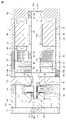
- FIG. 1 is a side sectional view showing an electric turbo compressor 1 according to an embodiment.
- the electric turbo compressor 1 has a cylindrical housing 10.
- Housing 10 has rear housing 11 , motor housing 12 , first compressor housing 13 , second compressor housing 14 , partition wall 15 , first intermediate housing 16 and second intermediate housing 17 .
- the rear housing 11, the motor housing 12, the first compressor housing 13, the second compressor housing 14, the partition wall 15, the first intermediate housing 16 and the second intermediate housing 17 are each made of a metal material, for example aluminum. be.
- the motor housing 12 has a bottomed tubular shape having a plate-shaped end wall portion 12a and a peripheral wall portion 12b extending in a tubular shape from the outer peripheral portion of the end wall portion 12a.
- the second intermediate housing 17 is connected to the motor housing 12 while closing the opening of the peripheral wall portion 12b on the side opposite to the end wall portion 12a.
- a motor chamber 18 is defined by the end wall portion 12 a of the motor housing 12 , the peripheral wall portion 12 b and the second intermediate housing 17 .
- the motor housing 12 is formed with a suction hole (not shown) for sucking refrigerant.
- the suction hole communicates with the motor chamber 18 . Therefore, the refrigerant is sucked into the motor chamber 18 through the suction hole.
- a circular shaft insertion hole 17 a is formed in the central portion of the second intermediate housing 17 .
- the second intermediate housing 17 has a cylindrical first bearing holding portion 19 .
- the first bearing holding portion 19 is formed on the inner peripheral surface of the second intermediate housing 17 .
- the inner side of the first bearing holding portion 19 communicates with the shaft insertion hole 17a.
- the central axis of the first bearing holding portion 19 and the central axis of the shaft insertion hole 17a coincide with each other.
- a first radial bearing 20 is held in the first bearing holding portion 19 .
- the end wall portion 12 a of the motor housing 12 has a cylindrical second bearing holding portion 21 .
- the second bearing holding portion 21 is formed in the central portion of the end wall portion 12 a of the motor housing 12 .
- the central axis of the first bearing holding portion 19 and the central axis of the second bearing holding portion 21 are aligned.
- a second radial bearing 22 is held in the second bearing holding portion 21 .
- a first radial bearing 20 and a second radial bearing 22 are arranged within the housing 10 .
- a first chamber-forming concave portion 17b is formed on the outer surface of the second intermediate housing 17 on the side opposite to the motor chamber 18 .
- the first chamber forming recess 17b communicates with the shaft insertion hole 17a.
- the second intermediate housing 17 has multiple communication holes 23 .
- Each communication hole 23 is positioned near the outer periphery of the second intermediate housing 17 .
- Each communication hole 23 penetrates through the second intermediate housing 17 .
- the communication hole 23 communicates the motor chamber 18 and the first chamber-forming concave portion 17b.
- the first intermediate housing 16 is connected to the second intermediate housing 17 .
- the first intermediate housing 16 is connected to the second intermediate housing 17 so as to block the opening of the first chamber forming recess 17b.
- a thrust bearing accommodating chamber 25 is defined by the first intermediate housing 16 and the first chamber-forming concave portion 17 b of the second intermediate housing 17 .
- a circular shaft insertion hole 16 a is formed in the central portion of the first intermediate housing 16 .
- the first intermediate housing 16 has a plurality of communication holes 16b. Each communication hole 16 b is located at a portion near the outer periphery of the first intermediate housing 16 . Each communication hole 16 b penetrates through the first intermediate housing 16 .
- a second chamber-forming concave portion 16 c is formed on the outer surface of the first intermediate housing 16 on the side opposite to the thrust bearing accommodating chamber 25 . The second chamber forming recess 16c communicates with the shaft insertion hole 16a. Each communicating hole 16b communicates between the thrust bearing housing chamber 25 and the second chamber-forming concave portion 16c.
- the first compressor housing 13 has a cylindrical shape with a circular first suction port 24 .
- the first compressor housing 13 is connected to the first intermediate housing 16 with the central axis of the first suction port 24 aligned with the central axis of the shaft insertion hole 16a.
- the first suction port 24 communicates with the second chamber-forming concave portion 16c.
- the partition wall 15 is connected to the end face of the first compressor housing 13 opposite to the first intermediate housing 16 .
- the partition wall 15 is plate-shaped.
- a circular through-hole 27 (FIG. 2) is formed in the central portion of the partition wall 15 .
- the through hole 27 penetrates the partition wall 15 in the thickness direction of the partition wall 15 .
- the partition wall 15 is connected to the first compressor housing 13 with the central axis of the through hole 27 aligned with the central axis of the first suction port 24 .
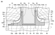
- FIG. 2 is a cross-sectional view showing an enlarged periphery of the impeller.
- a first impeller chamber 28 communicating with the first suction port 24 and a first impeller chamber 28 surrounding the first impeller chamber 28 .
- a first discharge chamber 29 extending around the central axis of the suction port 24 and a first diffuser flow path 30 communicating between the first impeller chamber 28 and the first discharge chamber 29 are formed.
- the second compressor housing 14 is connected to the end face of the partition wall 15 opposite to the first compressor housing 13 .
- An intermediate pressure chamber 31 is formed across the first compressor housing 13 , the partition wall 15 and the second compressor housing 14 .
- the intermediate pressure chamber 31 communicates with the first discharge chamber 29 via a passage (not shown).
- the second compressor housing 14 is formed with a circular second suction port 32 that communicates with the intermediate pressure chamber 31 .
- the first discharge chamber 29 and the second suction port 32 communicate with each other via the intermediate pressure chamber 31 .
- a second impeller chamber 33 communicating with the second suction port 32 and a second impeller chamber 33 extending around the central axis of the second suction port 32 around the second impeller chamber 33 .
- a second discharge chamber 34 and a second diffuser flow path 35 communicating between the second impeller chamber 33 and the second discharge chamber 34 are formed.
- the housing 10 has a first impeller chamber 28 and a second impeller chamber 33 .
- the partition wall 15 partitions the first impeller chamber 28 and the second impeller chamber 33 .
- the rear housing 11 is connected to the second compressor housing 14 .
- the rear housing 11 defines an intermediate pressure chamber 31 .
- the rear housing 11 is plate-shaped.
- the electric turbo compressor 1 has a rotating shaft 40 .
- the rotary shaft 40 extends from the inside of the second bearing holding portion 21 to the motor chamber 18, the inside of the first bearing holding portion 19, the shaft insertion hole 17a, the thrust bearing accommodation chamber 25, the shaft insertion hole 16a, the first suction port 24, the It extends in the axial direction of the housing 10 while passing through the first impeller chamber 28 , the through hole 27 , the second impeller chamber 33 and the second suction port 32 in this order.
- the rotating shaft 40 is arranged across the first impeller chamber 28 and the second impeller chamber 33 while being inserted through the through hole 27 .
- the rotating shaft 40 has a first end 40a as one end and a second end 40b as the other end.
- the first end 40 a is located within the second compressor housing 14 .
- the second end 40 b is located within the end wall 12 a of the motor housing 12 .
- the rotating shaft 40 is accommodated within the housing 10 .
- the axis L of the rotary shaft 40 extends through the first bearing holding portion 19, the second bearing holding portion 21, the shaft insertion hole 17a, the shaft insertion hole 16a, the first suction port 24, the through hole 27, and the second suction port 32, respectively. aligned with the central axis.
- the "axial direction of the rotating shaft 40” which is the direction in which the axis L of the rotating shaft 40 extends, will be referred to as the "thrust direction”
- the "radial direction of the rotating shaft 40" will be referred to as the "radial direction”.
- the first radial bearing 20 and the second radial bearing 22 rotatably support the rotating shaft 40 in the radial direction.
- the first radial bearing 20 and the second radial bearing 22 may be air dynamic pressure bearings.
- the electric turbo compressor 1 includes a disc-shaped support plate 75 provided on the rotating shaft 40 .
- the support plate 75 protrudes radially outward from the outer peripheral surface of the rotating shaft 40 .
- the support plate 75 rotates integrally with the rotating shaft 40 .
- the support plate 75 is arranged in the thrust bearing housing chamber 25 .
- Thrust bearings 80 are arranged between the first intermediate housing 16 and the support plate 75 and between the second intermediate housing 17 and the support plate 75, respectively. Both thrust bearings 80 rotatably support the rotating shaft 40 in the thrust direction. Both thrust bearings 80 may be air dynamic pressure bearings.
- the electric turbo compressor 1 has an electric motor 41 .
- the electric motor 41 is housed in the motor chamber 18 .
- the electric motor 41 is accommodated within the housing 10 .
- the electric motor 41 is an example of a drive source that rotationally drives the rotating shaft 40 .
- the electric motor 41 has a stator 42 and a rotor 43 .
- the stator 42 has a cylindrical stator core 44 and coils 45 wound around the stator core 44 .
- the stator core 44 is fixed to the inner peripheral surface of the peripheral wall portion 12 b of the motor housing 12 .
- the rotor 43 is arranged radially inside the stator core 44 in the motor chamber 18 .
- the rotor 43 rotates integrally with the rotating shaft 40 .
- the rotor 43 has a rotor core 43a fixed to the rotating shaft 40 and a plurality of permanent magnets (not shown) provided on the rotor core 43a. Electric power controlled by an inverter device (not shown) is supplied to the coil 45 to rotate the rotor 43 of the electric motor 41 .
- the rotating shaft 40 rotates integrally with the rotor 43 .
- the electric turbo compressor 1 has a first impeller 51 and a second impeller 52 .
- the first impeller 51 is made of aluminum, for example.
- the second impeller 52 is made of resin, for example.
- the first impeller 51 and the second impeller 52 are connected to the rotating shaft 40 .
- the first impeller 51 and the second impeller 52 rotate integrally with the rotating shaft 40 .
- the second impeller 52 is arranged closer to the first end 40a of the rotating shaft 40 than the first impeller 51 is.
- the first impeller 51 and the second impeller 52 are arranged closer to the first end 40 a of the rotating shaft 40 than the first radial bearing 20 is.
- the first impeller 51 is arranged closer to the electric motor 41 than the second impeller 52 is.
- the electric motor 41 , the first impeller 51 and the second impeller 52 are arranged in this order in the axial direction of the rotating shaft 40 .
- the first impeller 51 is housed in the first impeller chamber 28 .
- the second impeller 52 is housed in the second impeller chamber 33 .
- the first impeller 51 has a first hub 51H.
- the first hub 51H is fixed to the rotating shaft 40 .
- the first hub 51H has a back surface 51a, a tip surface 51b, an outer peripheral surface 51c, and a radial outer edge portion 51d.
- the back surface 51a, the tip surface 51b, the outer peripheral surface 51c, and the radially outer edge portion 51d form part of the outer surface of the first hub 51H.
- the first hub 51H has a substantially truncated conical shape with an outer diameter increasing from the front end surface 51b located on the first suction port 24 side toward the rear surface 51a.
- the rear surface 51a forms the rear end of the first hub 51H.
- the back surface 51a is the outer surface of the first hub 51H that does not form a coolant flow path.
- the rear surface 51 a faces the partition wall 15 in the axial direction of the rotating shaft 40 .
- the partition wall 15 has a first opposing surface 15a that faces the rear surface 51a of the first hub 51H in the axial direction of the rotating shaft 40. As shown in FIG.
- the tip surface 51b forms the front end of the first hub 51H.
- the tip end surface 51 b constitutes one end of the first impeller 51 in the axial direction of the rotating shaft 40 .
- the tip surface 51b is the end of the first hub 51H on the side where the coolant flows into the first impeller 51 .
- the outer peripheral surface (hub surface) 51c forms part of the inner wall surface of the first impeller chamber 28. As shown in FIG.
- the outer peripheral surface 51 c is a curved surface that is recessed toward the axis L of the rotating shaft 40 . At least a portion of the outer peripheral surface 51 c faces outward in the radial direction of the rotating shaft 40 .
- the outer peripheral surface 51c is formed such that its diameter gradually increases along the axial direction of the rotating shaft 40 from the front end surface 51b toward the rear surface 51a.
- the outer peripheral surface 51c is gradually inclined radially outward from the tip surface 51b toward the rear surface 51a.
- the radial outer edge portion 51d is a portion of the first impeller 51 having the largest outer diameter.
- the radial outer edge portion 51d has a cylindrical shape with a short axis.
- the first impeller 51 has an outer diameter R1.
- the outer diameter R1 of the first impeller 51 is the distance between the axis L of the rotating shaft 40 and the radial outer edge portion 51d of the first impeller 51 in the radial direction of the rotating shaft 40 .
- the first impeller 51 has a plurality of first blades 51B.
- the plurality of first wings 51B are provided on the outer peripheral surface 51c of the first hub 51H.
- the plurality of first blades 51B are arranged in the circumferential direction of the first hub 51H.
- the plurality of first blades 51B partition the first impeller chamber 28 in the circumferential direction, and form coolant flow paths between a pair of circumferentially adjacent first blades 51B.
- the plurality of first wings 51B protrude radially outward from the outer peripheral surface 51c of the first hub 51H.
- the plurality of first blades 51B are arranged at regular intervals in the circumferential direction on the outer peripheral surface 51c of the first hub 51H. The sensation between the first wings 51B adjacent to each other in the circumferential direction of the first hub 51H gradually widens from the front end to the rear end of the first hub 51H.
- the first blade 51B has a rear end 51Ba, a front end 51Bb, and a tip surface 51Bc.
- the rear end 51Ba, the front end 51Bb and the tip surface 51Bc constitute part of the edge of the first blade 51B.
- a front end 51Bb of the first wing 51B faces the first suction port 24 .
- a rear end 51Ba of the first blade 51B faces the first diffuser flow path 30.
- a tip surface 51 ⁇ /b>Bc of the first blade 51 ⁇ /b>B faces the first compressor housing 13 .
- the front end 51Bb extends radially of the rotating shaft 40 .
- the rear end 51Ba extends in the axial direction of the rotating shaft 40. As shown in FIG.
- the tip surface 51Bc is curved.
- the front end surface 51Bc is formed such that its diameter gradually increases along the axial direction of the rotating shaft 40 from the front end 51Bb toward the rear end 51Ba.
- the front end surface 51Bc is gradually inclined radially outward from the front end 51Bb to the rear end 51Ba.
- the curvature of the tip surface 51Bc of the first blade 51B is larger than the curvature of the outer peripheral surface 51c of the first hub 51H.
- the front end 51Bb is the edge of the first blade 51B on the upstream side in the coolant flow direction. Refrigerant flows from the first suction port 24 to between the pair of circumferentially adjacent first blades 51B via between the front ends 51Bb.
- the rear end 51Ba is the edge of the first blade 51B on the downstream side in the flow direction of the coolant. The coolant flows radially outward through between a pair of rear ends 51Ba adjacent in the circumferential direction.
- the second impeller 52 has a second hub 52H.
- the second hub 52H is fixed to the rotating shaft 40.
- the second hub 52H has a back surface 52a, a tip surface 52b, an outer peripheral surface 52c, and a radially outer edge portion 52d.
- the back surface 52a, the tip surface 52b, the outer peripheral surface 52c, and the radially outer edge portion 52d constitute part of the outer surface of the second hub 52H.
- the second hub 52H has a substantially truncated conical shape with an outer diameter that increases from the front end surface 52b located on the second suction port 32 side toward the rear surface 52a.
- the rear surface 52a forms the rear end of the second hub 52H.
- the rear surface 52a is the outer surface of the second hub 52H that does not form a coolant flow path.
- the rear surface 52 a faces the partition wall 15 in the axial direction of the rotating shaft 40 .
- the partition wall 15 has a second opposing surface 15b that faces the rear surface 52a of the second hub 52H in the axial direction of the rotating shaft 40. As shown in FIG.
- the tip surface 52b forms the front end of the second hub 52H.
- the tip surface 52b forms one end of the second impeller 52 in the axial direction of the rotating shaft 40.
- the tip surface 52b is the end of the second hub 52H on the side where the coolant flows into the second impeller 52. As shown in FIG.
- the outer peripheral surface (hub surface) 52c forms part of the inner wall surface of the second impeller chamber 33. As shown in FIG.
- the outer peripheral surface 52 c is a curved surface that is recessed toward the axis L of the rotating shaft 40 . At least a portion of the outer peripheral surface 52 c faces outward in the radial direction of the rotating shaft 40 .
- the outer peripheral surface 52c is formed such that its diameter gradually increases along the axial direction of the rotating shaft 40 from the front end surface 52b toward the rear surface 52a.
- the outer peripheral surface 52c is gradually inclined radially outward from the tip surface 52b toward the rear surface 52a.
- the radial outer edge portion 52d is a portion of the second impeller 52 having the largest outer diameter.
- the radial outer edge portion 52d has a cylindrical shape with a short axis.
- the second impeller 52 has an outer diameter R2.
- the outer diameter R2 of the second impeller 52 is the distance between the axis L of the rotating shaft 40 in the radial direction of the rotating shaft 40 and the radial outer edge portion 52d of the second impeller.
- the second impeller 52 has a plurality of second blades 52B.
- the plurality of second wings 52B are provided on the outer peripheral surface 52c of the second hub 52H.
- the plurality of second wings 52B are arranged in the circumferential direction of the second hub 52H.
- the plurality of second blades 52B partition the second impeller chamber 33 in the circumferential direction, and form coolant flow paths between a pair of circumferentially adjacent second blades 52B.
- the plurality of second wings 52B protrude radially outward from the outer peripheral surface 52c of the second hub 52H.
- the plurality of second wings 52B are arranged at regular intervals in the circumferential direction on the outer peripheral surface 52c of the second hub 52H. The sensation between the second wings 52B adjacent to each other in the circumferential direction of the second hub 52H gradually widens from the front end to the rear end of the second hub 52H.
- the second wing 52B has a rear end 52Ba, a front end 52Bb, and a tip surface 52Bc.
- the rear end 52Ba, the front end 52Bb and the tip surface 52Bc constitute part of the edge of the second blade 52B.
- a front end 52 ⁇ /b>Bb of the second wing 52 ⁇ /b>B faces the second inlet 32 .
- a rear end 52Ba of the second blade 52B faces the second diffuser flow path 35 .
- a tip surface 52Bc of the second blade 52B faces the second compressor housing 14 .
- the front end 52Bb extends radially of the rotating shaft 40 .
- the rear end 52Ba extends in the axial direction of the rotating shaft 40. As shown in FIG.
- the distal end surface 52Bc is curved.
- the front end surface 52Bc is formed such that its diameter gradually increases along the axial direction of the rotating shaft 40 from the front end 52Bb toward the rear end 52Ba.
- the tip surface 52Bc is gradually inclined radially outward from the front end 52Bb toward the rear end 52Ba.
- the curvature of the tip surface 52Bc of the second blade 52B is larger than the curvature of the outer peripheral surface 52c of the second hub 52H.
- the front end 52Bb is the edge of the second blade 52B on the upstream side in the coolant flow direction. Refrigerant flows from the second suction port 32 through between the front ends 52Bb and between the pair of second blades 52B adjacent in the circumferential direction.
- the rear end 52Ba is the edge of the second blade 52B on the downstream side in the flow direction of the coolant. The coolant flows radially outward through between a pair of rear ends 52Ba adjacent in the circumferential direction.
- the electric motor 41 rotates a rotating body including the rotating shaft 40, the first impeller 51 and the second impeller 52, and rotates the rotating body around the axis L integrally.
- the first impeller 51 compresses the refrigerant by rotating integrally with the rotating shaft 40 .
- the second impeller 52 rotates integrally with the rotating shaft 40 to compress the refrigerant that has been compressed by the first impeller 51 .
- a first impeller 51 is arranged on the upstream side in the flow direction of the refrigerant, and a second impeller 52 is arranged on the downstream side.
- the first impeller 51 and the second impeller 52 are provided on the rotating shaft 40 such that the rear surface 51a of the first hub 51H and the rear surface 52a of the second hub 52H face each other with the partition wall 15 interposed therebetween.
- a hollow cylindrical spacer 54 is arranged between the first impeller 51 and the second impeller 52 .
- the spacer 54 has a first end facing the rear surface 51a of the first hub 51H and a second end facing the rear surface 52a of the second hub 52H.
- the dimension of the spacer 54 in the axial direction of the rotating shaft 40 is slightly larger than the distance between the first opposing surface 15a and the second opposing surface 15b of the partition wall 15. As shown in FIG.
- the spacer 54 has the function of sealing the gap between the outer peripheral surface of the rotating shaft 40 and the inner peripheral surface of the through hole 27 .
- a fitting member 55 is attached to the outer peripheral surface of the rotating shaft 40 at the first end 40 a of the rotating shaft 40 .
- the fitting member 55 has a hollow cylindrical shape.
- the fitting member 55 is attached to the rotary shaft 40 by screw action, for example.
- the fitting member 55 is in contact with the tip surface 52b of the second hub 52H.
- the fitting member 55 supports the second impeller 52 in the axial direction of the rotating shaft 40 .
- the first compressor housing 13 has a first shroud 53 a that cooperates with the partition wall 15 to partition the first impeller chamber 28 .
- the first shroud 53a has a truncated cone shape that covers the first impeller 51 from the radial outside.
- the first shroud 53a faces the outer peripheral surface 51c of the first hub 51H.
- the first shroud 53a extends along the outer peripheral surface 51c of the first hub 51H from the rear surface 51a to the tip surface 51b of the first hub 51H.
- the first shroud 53a surrounds the plurality of first wings 51B.
- the first shroud 53a faces the tip end surface 51Bc of the first blade 51B and forms part of the inner wall surface of the first impeller chamber .
- a pair of the first blades 51B, the first hub 51H, and the first shroud 53a which are adjacent in the circumferential direction of the first hub 51H, radially form coolant flow paths.
- a first tip clearance 61 is formed between the first impeller 51 and the first shroud 53a.
- the first tip clearance 61 is a gap extending from the front end 51Bb to the rear end 51Ba of the first blade 51B between the tip surface 51Bc of the first blade 51B and the first shroud 53a of the first compressor housing 13.
- the second compressor housing 14 has a second shroud 53 b that cooperates with the partition wall 15 to partition the second impeller chamber 33 .
- the second shroud 53b has a truncated cone shape that covers the second impeller 52 from the outside in the radial direction.
- the second shroud 53b faces the outer peripheral surface 52c of the second hub 52H.
- the second shroud 53b extends along the outer peripheral surface 52c of the second hub 52H from the rear surface 52a to the tip surface 52b of the second hub 52H.
- the second shroud 53b surrounds the plurality of second wings 52B.
- the second shroud 53b faces the tip surface 52Bc of the second blade 52B and forms part of the inner wall surface of the second impeller chamber 33.
- a pair of the second blades 52B, the second hub 52H, and the second shroud 53b which are adjacent to each other in the circumferential direction of the second hub 52H, form a radial flow path for the coolant.
- a second tip clearance 62 is formed between the second impeller 52 and the second shroud 53b.
- the second tip clearance 62 is a gap extending from the front end 52Bb to the rear end 52Ba of the second blade 52B between the tip surface 52Bc of the second blade 52B and the second shroud 53b of the second compressor housing 14 .
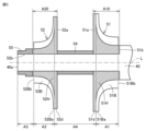
- FIG. 3 is a cross-sectional view explaining each region set on the rotating body.
- the rotating body including the rotating shaft 40, the first impeller 51 and the second impeller 52, along the axial direction of the rotating shaft 40, from the front end 51Bb of the first blade 51B to the rear end 51Ba A region is set as a first region A1.
- a region from the front end 52Bb to the rear end 52Ba of the second blade 52B along the axial direction of the rotating shaft 40 is set as a second region A2.
- the first end 40a is set as the third area A3.
- the first end portion 40 a is one end of the pair of end portions of the rotating shaft 40 on the side opposite to the electric motor 41 with respect to the first impeller 51 and the second impeller 52 .
- an area from the first blade 51B to the second blade 52B along the axial direction of the rotating shaft is set as a fourth area A4.
- a region from the back surface 51a to the tip surface 51b of the first hub 51H along the axial direction of the rotating shaft 40 is set as the first expansion region A10.
- a region from the back surface 52a to the tip surface 52b of the second hub 52H along the axial direction of the rotating shaft 40 is set as a second expanded region A20.
- the mass of the first region A1 in the rotating body is larger than the mass of the second region A2 in the rotating body.
- the mass of the first area A1 includes the mass of the rotating shaft 40 and the mass of the first impeller 51, that is, the mass of the first hub 51H and the first blades 51B.
- the mass of the second area A2 includes the mass of the rotating shaft 40 and the mass of the second impeller 52, that is, the mass of the second hub 52H and the second blades 52B.
- the mass of the first expansion region A10 in the rotor is larger than the mass of the second expansion region A20 in the rotor.
- the mass of the first expansion area A10 includes the mass of the rotating shaft 40 and the mass of the first impeller 51, that is, the mass of the first hub 51H and the first blades 51B.
- the mass of the second expansion area A20 includes the mass of the rotating shaft 40 and the mass of the second impeller 52, that is, the mass of the second hub 52H and the second blades 52B.
- the mass of the first impeller 51 alone is greater than the mass of the second impeller 52 alone.
- the outer diameter R1 of the first impeller 51 is larger than the outer diameter R2 of the second impeller 52.
- the overall axial length of the first impeller 51 is longer than the axial length of the second impeller 52 .
- the specific gravity of the material of the first impeller 51 is higher than the specific gravity of the material of the second impeller 52 .
- the rotating shaft 40 has a uniform outer diameter over the area from the front end 51Bb of the first blade 51B to the first end 40a.
- the mass of the second region A2 in the rotating body is larger than the mass of the third region A3 in the rotating body.
- the mass of the third area A3 includes the mass of the rotating shaft 40 and the mass of the fitting member 55 .
- the mass of the third area A3 includes the mass of the second hub 52H.
- the mass of the first area A1 in the rotating body is larger than the mass of the fourth area A4 in the rotating body.
- the mass of the fourth area A4 includes the mass of the rotating shaft 40, the mass of the spacer 54, the mass of the first hub 51H, and the mass of the second hub 52H.
- the refrigerant is sucked into the motor chamber 18 through a suction hole (not shown).
- the refrigerant sucked into the motor chamber 18 passes through the communication holes 23 , the thrust bearing housing chamber 25 , the communication holes 16 b , and the second chamber forming recess 16 c to be sucked into the first suction port 24 .
- the refrigerant sucked into the first suction port 24 is pressurized by the centrifugal action of the first impeller 51, sent from the first impeller chamber 28 into the first diffuser passage 30, and further pressurized in the first diffuser passage 30. be done.
- the refrigerant that has passed through the first diffuser flow path 30 is discharged into the first discharge chamber 29 .
- Refrigerant discharged into the first discharge chamber 29 passes through the intermediate pressure chamber 31 and is sucked into the second suction port 32 .
- the refrigerant sucked into the second suction port 32 is pressurized by the centrifugal action of the second impeller 52, sent from the second impeller chamber 33 to the second diffuser passage 35, and further pressurized in the second diffuser passage 35. be done.
- the refrigerant that has passed through the second diffuser flow path 35 is discharged into the second discharge chamber 34 .
- the second ejection chamber 34 communicates with an ejection port (not shown).
- the refrigerant compressed by the electric turbo-compressor 1 is discharged to the outside of the electric turbo-compressor 1 from its discharge port.
- the second impeller 52 is arranged closer to the first end 40a of the rotating shaft 40 than the first impeller 51 is.
- the second impeller 52 arranged on the tip side of the rotating shaft 40 may vibrate more than the first impeller 51 during operation.
- the electric turbo compressor 1 of the embodiment can perform efficient two-stage compression.
- the mass in the region from the back surface 51a to the tip surface 51b of the first hub 51H along the axial direction is equal to that of the second hub along the axial direction. It is larger than the mass in the area from the back surface 52a of 52H to the tip surface 52b.
- the mass of the first region A1 shown in FIG. It becomes easy to make the mass larger than the mass, and it becomes easy to make the mass of the first expansion region A10 larger than the mass of the second expansion region A20.
- the mass of the first region A1 is reduced to that of the second region A2.
- the mass of the first expansion region A10 can be easily made larger than the mass of the second expansion region A20.
- the mass in the region from the front end 52Bb to the rear end 52Ba of the second blade 52B along the axial direction is the second It is larger than the mass in the area from the blades 52B to the first end 40a, which is the end of the rotating shaft 40 on the side where the second impeller 52 is arranged.
- the mass in the region from the front end 51Bb to the rear end 51Ba of the first blade 51B along the axial direction is equal to the mass of the first blade along the axial direction It is larger than the mass in the area from 51B to the second wing 52B.
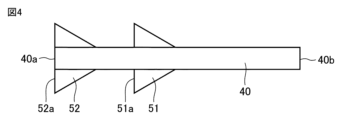
- FIG. 4 is a schematic diagram schematically showing a modification of the impeller arrangement. As shown in FIG. 4 , the first impeller 51 and the second impeller 52 are arranged such that the tip surfaces 51 b and 52 b face the second end 40 b of the rotating shaft 40 and the back surfaces 51 a and 52 a face the first end of the rotating shaft 40 . It may be arranged to face 40a.
- the second impeller 52 is arranged closer to the first end 40a of the rotating shaft 40, and the mass in the region from the front end 51Bb to the rear end 51Ba of the first blade 51B along the axial direction is By setting the mass larger than the mass in the region from the front end 52Bb to the rear end 52Ba of the second blade 52B, the amount of deflection of the second impeller 52 can be reduced, and the reliability of the electric turbo compressor 1 can be improved. can.
- the rotating shaft 40, the first impeller 51, and the second impeller 52 are separate members.
- the rotating shaft 40 and the first impeller 51 may be integrally formed.
- the rotating shaft 40 and the second impeller 52 may be integrally formed.
- the first impeller 51, the second impeller 52, and the spacer 54 are separate members. may be an integral member.
- the fitting member 55 is in contact with the tip surface 52b of the second hub 52H, and the entire fitting member 55 is arranged in the third region A3. may be placed in the second area A2.
- the electric turbo compressor 1 described in the embodiment is a centrifugal compressor, but the technical idea of the present disclosure can also be applied to a mixed flow compressor.
Landscapes
- Engineering & Computer Science (AREA)
- Mechanical Engineering (AREA)
- General Engineering & Computer Science (AREA)
- Structures Of Non-Positive Displacement Pumps (AREA)
- Physics & Mathematics (AREA)
- Fluid Mechanics (AREA)
Priority Applications (4)
| Application Number | Priority Date | Filing Date | Title |
|---|---|---|---|
| DE112022004553.1T DE112022004553T5 (de) | 2021-09-24 | 2022-03-15 | Elektrischer turbokompressor |
| KR1020247008800A KR20240045313A (ko) | 2021-09-24 | 2022-03-15 | 전동 터보식 압축기 |
| US18/693,266 US12448979B2 (en) | 2021-09-24 | 2022-03-15 | Electric turbo compressor |
| CN202280052024.4A CN117716133A (zh) | 2021-09-24 | 2022-03-15 | 电动涡轮式压缩机 |
Applications Claiming Priority (2)
| Application Number | Priority Date | Filing Date | Title |
|---|---|---|---|
| JP2021-155714 | 2021-09-24 | ||
| JP2021155714A JP7593279B2 (ja) | 2021-09-24 | 2021-09-24 | 電動ターボ式圧縮機 |
Publications (1)
| Publication Number | Publication Date |
|---|---|
| WO2023047652A1 true WO2023047652A1 (ja) | 2023-03-30 |
Family
ID=85720366
Family Applications (1)
| Application Number | Title | Priority Date | Filing Date |
|---|---|---|---|
| PCT/JP2022/011620 Ceased WO2023047652A1 (ja) | 2021-09-24 | 2022-03-15 | 電動ターボ式圧縮機 |
Country Status (6)
| Country | Link |
|---|---|
| US (1) | US12448979B2 (enExample) |
| JP (1) | JP7593279B2 (enExample) |
| KR (1) | KR20240045313A (enExample) |
| CN (1) | CN117716133A (enExample) |
| DE (1) | DE112022004553T5 (enExample) |
| WO (1) | WO2023047652A1 (enExample) |
Cited By (1)
| Publication number | Priority date | Publication date | Assignee | Title |
|---|---|---|---|---|
| CN117514781A (zh) * | 2023-11-08 | 2024-02-06 | 西安陕鼓动力股份有限公司 | 一种齿轮式压缩机双悬臂转子及其稳定性提高方法 |
Citations (3)
| Publication number | Priority date | Publication date | Assignee | Title |
|---|---|---|---|---|
| JPS54117916A (en) * | 1978-03-07 | 1979-09-13 | Kawasaki Heavy Ind Ltd | Multi-stage turbo compressor |
| JPH08509802A (ja) * | 1993-05-04 | 1996-10-15 | エコエアー コーポレーション | ゼロ過熱冷凍圧縮システム |
| JP2000161297A (ja) * | 1998-11-30 | 2000-06-13 | Ishikawajima Harima Heavy Ind Co Ltd | 多段遠心圧縮機 |
Family Cites Families (7)
| Publication number | Priority date | Publication date | Assignee | Title |
|---|---|---|---|---|
| JP6213500B2 (ja) * | 2014-03-19 | 2017-10-18 | 株式会社豊田自動織機 | 電動ターボ式圧縮機 |
| JP5905517B2 (ja) | 2014-06-23 | 2016-04-20 | 三菱重工業株式会社 | インペラ |
| JP2016102481A (ja) * | 2014-11-28 | 2016-06-02 | 株式会社豊田自動織機 | ターボ式圧縮機 |
| WO2017094161A1 (ja) | 2015-12-03 | 2017-06-08 | 三菱重工コンプレッサ株式会社 | ロータのバランス調整方法 |
| JP6984383B2 (ja) | 2017-12-15 | 2021-12-17 | 株式会社Ihi | 回転機械 |
| KR102252548B1 (ko) * | 2018-05-17 | 2021-05-14 | 미츠비시 쥬고교 가부시키가이샤 | 모터에 의해 구동 가능한 과급기의 진동 억제 방법 및 진동 억제 장치 |
| KR102746986B1 (ko) * | 2018-12-24 | 2024-12-27 | 엘지전자 주식회사 | 2단 원심식 압축기 |
-
2021
- 2021-09-24 JP JP2021155714A patent/JP7593279B2/ja active Active
-
2022
- 2022-03-15 WO PCT/JP2022/011620 patent/WO2023047652A1/ja not_active Ceased
- 2022-03-15 CN CN202280052024.4A patent/CN117716133A/zh active Pending
- 2022-03-15 DE DE112022004553.1T patent/DE112022004553T5/de active Pending
- 2022-03-15 KR KR1020247008800A patent/KR20240045313A/ko active Pending
- 2022-03-15 US US18/693,266 patent/US12448979B2/en active Active
Patent Citations (3)
| Publication number | Priority date | Publication date | Assignee | Title |
|---|---|---|---|---|
| JPS54117916A (en) * | 1978-03-07 | 1979-09-13 | Kawasaki Heavy Ind Ltd | Multi-stage turbo compressor |
| JPH08509802A (ja) * | 1993-05-04 | 1996-10-15 | エコエアー コーポレーション | ゼロ過熱冷凍圧縮システム |
| JP2000161297A (ja) * | 1998-11-30 | 2000-06-13 | Ishikawajima Harima Heavy Ind Co Ltd | 多段遠心圧縮機 |
Cited By (1)
| Publication number | Priority date | Publication date | Assignee | Title |
|---|---|---|---|---|
| CN117514781A (zh) * | 2023-11-08 | 2024-02-06 | 西安陕鼓动力股份有限公司 | 一种齿轮式压缩机双悬臂转子及其稳定性提高方法 |
Also Published As
| Publication number | Publication date |
|---|---|
| JP7593279B2 (ja) | 2024-12-03 |
| KR20240045313A (ko) | 2024-04-05 |
| US20250003414A1 (en) | 2025-01-02 |
| DE112022004553T5 (de) | 2024-08-08 |
| JP2023046876A (ja) | 2023-04-05 |
| CN117716133A (zh) | 2024-03-15 |
| US12448979B2 (en) | 2025-10-21 |
Similar Documents
| Publication | Publication Date | Title |
|---|---|---|
| KR20050072931A (ko) | 터보압축기 | |
| EP2597314A2 (en) | Axial-flow fan | |
| EP3712439B1 (en) | Blower | |
| JP2002285994A (ja) | ターボ圧縮機 | |
| JP7593279B2 (ja) | 電動ターボ式圧縮機 | |
| WO2023228760A1 (ja) | 遠心圧縮機 | |
| JPH07259798A (ja) | 遠心送風機 | |
| JP7593275B2 (ja) | 電動ターボ式圧縮機 | |
| CN113944653B (zh) | 离心压缩机 | |
| CN113958536B (zh) | 离心压缩机 | |
| KR100304564B1 (ko) | 터보압축기의레이디얼베어링구조 | |
| JP2023069205A (ja) | 電動圧縮機 | |
| KR20240071499A (ko) | 터보식 공기압축기 | |
| KR100253251B1 (ko) | 터보 압축기의 구동모터 | |
| KR100279608B1 (ko) | 터보 압축기 | |
| JP2024014301A (ja) | 遠心圧縮機 | |
| KR100405984B1 (ko) | 터보 압축기의 디퓨저 장착구조 | |
| KR100304562B1 (ko) | 터보압축기 | |
| KR100304563B1 (ko) | 터보압축기 | |
| WO2024079950A1 (ja) | 遠心圧縮機 | |
| WO2024111584A1 (ja) | 遠心圧縮機 | |
| KR100320207B1 (ko) | 터보 압축기 | |
| JP2026061113A (ja) | モータポンプ | |
| KR20010011627A (ko) | 터보 압축기의 모터 고정자 구조 | |
| JP2023088583A (ja) | 遠心圧縮機 |
Legal Events
| Date | Code | Title | Description |
|---|---|---|---|
| 121 | Ep: the epo has been informed by wipo that ep was designated in this application |
Ref document number: 22872411 Country of ref document: EP Kind code of ref document: A1 |
|
| WWE | Wipo information: entry into national phase |
Ref document number: 202280052024.4 Country of ref document: CN |
|
| WWE | Wipo information: entry into national phase |
Ref document number: 18693266 Country of ref document: US |
|
| WWE | Wipo information: entry into national phase |
Ref document number: 112022004553 Country of ref document: DE |
|
| 122 | Ep: pct application non-entry in european phase |
Ref document number: 22872411 Country of ref document: EP Kind code of ref document: A1 |
|
| WWG | Wipo information: grant in national office |
Ref document number: 18693266 Country of ref document: US |