WO2023042657A1 - イオンセンサ、及び被検出物質の検出方法 - Google Patents
イオンセンサ、及び被検出物質の検出方法 Download PDFInfo
- Publication number
- WO2023042657A1 WO2023042657A1 PCT/JP2022/032626 JP2022032626W WO2023042657A1 WO 2023042657 A1 WO2023042657 A1 WO 2023042657A1 JP 2022032626 W JP2022032626 W JP 2022032626W WO 2023042657 A1 WO2023042657 A1 WO 2023042657A1
- Authority
- WO
- WIPO (PCT)
- Prior art keywords
- ion
- solution
- ion sensor
- sensor
- electrode
- Prior art date
- Legal status (The legal status is an assumption and is not a legal conclusion. Google has not performed a legal analysis and makes no representation as to the accuracy of the status listed.)
- Ceased
Links
Images


Classifications
-
- G—PHYSICS
- G01—MEASURING; TESTING
- G01N—INVESTIGATING OR ANALYSING MATERIALS BY DETERMINING THEIR CHEMICAL OR PHYSICAL PROPERTIES
- G01N27/00—Investigating or analysing materials by the use of electric, electrochemical, or magnetic means
- G01N27/26—Investigating or analysing materials by the use of electric, electrochemical, or magnetic means by investigating electrochemical variables; by using electrolysis or electrophoresis
- G01N27/28—Electrolytic cell components
- G01N27/30—Electrodes, e.g. test electrodes; Half-cells
- G01N27/301—Reference electrodes
-
- G—PHYSICS
- G01—MEASURING; TESTING
- G01N—INVESTIGATING OR ANALYSING MATERIALS BY DETERMINING THEIR CHEMICAL OR PHYSICAL PROPERTIES
- G01N27/00—Investigating or analysing materials by the use of electric, electrochemical, or magnetic means
- G01N27/26—Investigating or analysing materials by the use of electric, electrochemical, or magnetic means by investigating electrochemical variables; by using electrolysis or electrophoresis
- G01N27/403—Cells and electrode assemblies
- G01N27/414—Ion-sensitive or chemical field-effect transistors, i.e. ISFETS or CHEMFETS
- G01N27/4141—Ion-sensitive or chemical field-effect transistors, i.e. ISFETS or CHEMFETS specially adapted for gases
Definitions
- the present disclosure relates to an ion sensor and a detection method for a substance to be detected.
- the ion sensor is equipped with an ion detection element.
- an ion sensor there is a pH sensor.
- a pH glass electrode and an ISFET (Ion Sensitive Field Effect Transistor) are known as ion detection elements.
- a pH sensor is disclosed in Non-Patent Document 1.
- the ISFET is disclosed in Non-Patent Documents 2 and 3.
- an ion sensor capable of shortening the time until the output stabilizes, and a method of detecting a substance to be detected.
- the ion sensor includes an ion detection element, a reference electrode that provides a reference point for potential, and a solution whose ion concentration is variable in the sensing area of the ion detection element.
- the sensing area of the ion sensing element is positioned in the solution.
- the sensing area of the ion detection element is arranged in a solution. Therefore, the ion detection element is in a state where the drift of the output has settled down. As a result, by using the ion sensor that is one aspect of the present disclosure, the time until the output stabilizes can be shortened.
- the ion sensor includes an ion detection element, a reference electrode that provides a potential reference point, and a solution that can change ion concentration in a sensing area of the ion detection element.
- the sensing area of the ion sensing element is placed in solution.
- the substance to be detected bound to a label having a function of changing the amount of ions detectable by the ion sensor is introduced into the solution, and the ion sensor is used to detect the label. It detects changes in the amount of ions depending on the concentration.
- An ion sensor is used in a method for detecting a substance to be detected, which is another aspect of the present disclosure.
- the sensing area of the ion sensing element is placed in a solution. Therefore, the ion detection element is in a state where the drift of the output has settled down.
- the method for detecting a substance to be detected which is another aspect of the present disclosure, can shorten the time until the output of the ion sensor stabilizes.
- FIG. 2 is a side cross-sectional view showing the configuration of a sensor unit and its surroundings in the first embodiment; It is a graph showing the result of continuously acquiring the output of the ion sensor from the time when the solution was introduced into the container. It is a graph showing the result of continuously detecting the pH of the solution immediately after replacing the solution.
- FIG. 2 is an explanatory diagram showing metabolism that occurs in solution; It is a graph showing the amount of change in the pH of the solution 60 minutes after adding each sample to the solution.
- 7A is a side cross-sectional view showing the configuration of the groove, FIG.
- FIG. 7B is a side cross-sectional view showing the configuration of the double formed protrusion
- FIG. 7C is a side cross-sectional view showing the configuration of the double formed groove. It is a sectional side view showing.
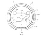
- FIG. 2 is a cross-sectional view showing a VIII-VIII cross section in FIG. 1; It is a perspective view showing the structure of the ion sensor in 2nd Embodiment. It is the top view which looked at the ion sensor in 2nd Embodiment from the viewpoint PX.
- FIG. 11 is a plan view of the ion sensor in the second embodiment as viewed from a viewpoint PY; It is a sectional side view showing the structure of the ion sensor in 3rd Embodiment.
- FIG. 13A is a plan view showing the configuration of the grooves of the sensor section viewed from the viewpoint PX
- FIG. 13B is a plan view showing the configuration of the protrusions of the double-formed sensor section viewed from the viewpoint PX
- FIG. 13C is a plan view showing the configuration of the grooves of the double-formed sensor section viewed from the viewpoint PX.
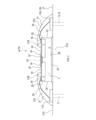
- the ion sensor 1 includes a sensor unit 3, a reference electrode 5 that provides a reference point of potential, a solution 7, a container 9, ISFET connection terminals 11, 13, 15, and a reference electrode connection terminal. 17 and.
- the container 9 is composed of a bottom portion 21, a side portion 23, and a lid 25. Lid 25 is removable. When the lid 25 is attached, the interior of the container 9 is sealed.
- the bottom part 21 is made of, for example, a molded body, a printed circuit board, or the like.
- the side portion 23 has a cylindrical shape.
- the bottom 21 is attached to one of the two ends provided by the side 23 .
- the lid 25 is attached to the other of the two ends of the side portion 23 opposite to the one. The bottom 21 and the lid 25 close the two end openings of the side 23 .
- the connecting portion between the side portion 23 and the bottom portion 21 is sealed by, for example, a screw structure, an adhesive such as epoxy, welding using laser or heat, press fitting, sealing via a gasket such as an O-ring, insert molding, or the like.
- a gasket such as an O-ring, insert molding, or the like.
- the joint between the side portion 23 and the lid 25 is sealed with, for example, an elastic material such as rubber, a screw structure, an aluminum pouch, a film, or the like.
- the direction from the bottom 21 to the lid 25 is defined as the X direction.
- the direction opposite to the X direction be the Y direction.
- the ion sensor 1 is normally used with the Y direction aligned with the vertical direction.
- the surface on the X-direction side is defined as an X-side surface 21X.
- the surface on the Y-direction side is referred to as a Y-side surface 21Y.
- the bottom portion 21 includes a concave portion 21A and a convex portion 21B.
- the X-side surface 21X protrudes in the X direction more than the concave portion 21A.
- the concave portion 21A when viewed from the viewpoint PX, the concave portion 21A is positioned on the center side, and the convex portion 21B is positioned on the end side.
- the concave portion 21A has a circular shape
- the convex portion 21B has an annular shape.
- the sensor unit 3 has an ISFET.
- the ISFET corresponds to the ion sensing element.
- the sensor unit 3 is arranged inside the container 9 as shown in FIG. As shown in FIG. 2, the sensor unit 3 is fixed to the X-side surface 21X by a fixing member 26 in the recess 21A.
- the surface of the sensor section 3 includes an X-side surface 3A, a Y-side surface 3B, and an end surface 3C.
- the X-side surface 3A is the principal surface on the X-direction side.
- the X-side surface 3A is in contact with the solution 7.
- the Y-side surface 3B is the principal surface on the Y-direction side.
- the fixing member 26 is in contact with the Y-side surface 3B.
- 3 C of end surfaces are end surfaces which comprise the outer peripheral edge of the sensor part 3, when it sees from the viewpoint PX.
- a protective member 27 is attached to the recess 21A.
- the protective member 27 is arranged to surround the sensor section 3 when viewed from the viewpoint PX.
- the protective member 27 is in contact with a contact portion 3D that is part of the surface of the sensor portion 3.
- the contact portion 3D includes an end face 3C.
- the contact portion 3D also includes a portion of the X-side surface 3A that is located on the end surface 3C side.
- the contact portion 3D includes an edge between the end surface 3C and the surface 3A. However, the contact portion 3D does not include a sensing area 29, which will be described later.
- the protective member 27 is in contact with the X-side surface 21X around the sensor section 3 .
- the protection member 27 includes a fill agent 27A and a dam agent 27B.
- the dam agent 27B is located on the X-side surface 3A.
- the dam agent 27B is positioned closer to the sensing area 29 than the filling agent 27A.
- the dam agent 27B suppresses the filling agent 27A from advancing in the direction of the sensing area 29. As shown in FIG.
- a plurality of bonding wires 28 are provided inside the protective member 27 .
- the bonding wire 28 is covered with a protective member 27 .
- the protective member 27 is made of an insulating material such as epoxy resin.
- the protective member 27 has functions of protecting and insulating the bonding wire 28 and protecting the end surface 3C.
- the bonding wires 28 electrically connect the ISFET provided in the sensor section 3 and the ISFET connection terminals 11 , 13 , 15 .
- a sensing area 29 is provided on the X-side surface 3A.
- the sensing area 29 detects ions to be detected by the ISFET (hereinafter referred to as target ions).
- the target ions are hydrogen ions.
- the sensing area 29 is located near the center of the surface 3A on the X side when viewed from the viewpoint PX. Sensing area 29 is not covered with protective member 27 .
- the sensor section 3 includes a gate insulating film 34 and an aluminum pad 36 on the X direction side.
- the X-side surface 3A is the surface of the gate insulating film 34 .
- the aluminum pad 36 is provided for electrical connection with the bonding wire 28 .
- a projecting portion 30 is formed on the X-side surface 3A.
- the projection 30 When viewed from the viewpoint PX, the projection 30 has an annular shape.
- the projecting portion 30 is arranged to surround the sensing area 29 .
- the protective member 27 is positioned outside the projecting portion 30 when viewed from the viewpoint PX.
- a portion of the projecting portion 30 is provided between the sensing area 29 and the protective member 27 .
- the protruding portion 30 protrudes in the X direction as compared with the surrounding X-side surface 3A. Therefore, a step 32 is formed between the projecting portion 30 and the surrounding X-side surface 3A.
- a reference electrode 5 is arranged inside a container 9 .
- the reference electrode 5 is attached to the X-side surface 21X at the projection 21B.
- the reference electrode 5 is located on the X direction side of the sensor section 3 . That is, the reference electrode 5 is located closer to the lid 25 than the sensor section 3 is.
- the reference electrode 5 is an Ag/AgCl electrode.
- the solution 7 is contained in a container 9.
- the solution 7 is a solution whose ion concentration can be changed in the sensing area 29 .
- Solution 7 is an aqueous solution containing chloride ions.
- the concentration of chloride ions is between 0.01M and 3M. When the chloride ion concentration is 0.01M to 3M, the output fluctuation of the ion sensor 1 can be further suppressed.
- the output of the ion sensor 1 is, for example, a current value associated with the potential change of the sensing area 29 .
- Chloride ions are ions necessary for the redox reaction of the reference electrode 5 .
- the solution 7 is stored in the container 9 even when the ion sensor 1 is not used, for example.
- the sensor section 3 is arranged in the solution 7. Therefore, the sensing area 29 is also arranged in the solution 7 .
- a reference electrode 5 is also placed in the solution 7 .
- the reference electrode 25 is positioned closer to the surface of the solution 7 than the sensor section 3 .
- the ISFET connection terminals 11, 13, 15 and the reference electrode connection terminal 17 are members made of a conductive material such as metal.
- the ISFET connection terminals 11, 13, 15 and the reference electrode connection terminal 17 are embedded in the bottom portion 21 by resin molding.
- the ISFET connection terminal 11 has an electrode portion 11X exposed on the X-side surface 21X.
- the bonding wire 28 is connected to the ISFET connection terminal 11 at the electrode portion 11X.
- the electrode portion 11X is covered with a protective member 27.
- the ISFET connection terminal 11 also includes an electrode portion 11Y exposed on the Y-side surface 21Y.
- the ISFET connection terminal 13 has an electrode portion 13X exposed on the X-side surface 21X.
- the bonding wire 28 is connected to the ISFET connection terminal 13 at the electrode portion 13X.
- the electrode portion 13X is covered with a protective member 27.
- the ISFET connection terminal 13 also includes an electrode portion 13Y exposed on the Y-side surface 21Y.
- the ISFET connection terminal 15 has an electrode portion 15X exposed on the X-side surface 21X.
- the bonding wire 28 is connected to the ISFET connection terminal 15 at the electrode portion 15X.
- the electrode portion 15X is covered with a protective member 27.
- the ISFET connection terminal 15 also includes an electrode portion 15Y exposed on the Y-side surface 21Y.
- the reference electrode connection terminal 17 is electrically connected to the reference electrode 5 .
- the reference electrode connection terminal 17 includes an electrode portion 17Y exposed on the Y-side surface 21Y.
- the electrode units 11Y, 13Y, 15Y, and 17Y can output the signal of the ion sensor 1 to an external device.
- the gas is, for example, an inert gas.
- An inert gas is, for example, nitrogen or the like.
- the ion sensor 1 can be used, for example, as follows. Remove the lid 25 and add the substance to be detected to the solution 7 . After that, the internal space of the container 9 was sealed with the lid 25, and the gas inside the container 9 was replaced with an inert gas.
- the substance to be detected may be solid, liquid, or gas. By adding the substance to be detected, the amount of target ions in the solution 7 changes.
- the amount of target ions in the solution 7 changes by causing a reaction in which target ions are generated or consumed by the label bound to the substance to be detected.
- the substance involved in the reaction that produces or consumes the target ion may be included in the solution 7 before the ion sensor 1 is used, or may be added to the solution 7 when the ion sensor 1 is used.
- the surface potential of the sensing area 29 changes based on the potential applied by the reference electrode 5 . This change in surface potential changes the amount of free electrons attracted to the semiconductor surface inside the ISFET.
- the change in the amount of ions is detected by measuring the current value associated with the change in the amount of free electrons.
- the ion sensor 1 detects changes in the amount of ions according to the concentration of the label.
- the ion sensor 1 is used.
- the ion sensor 1 is the one described in the section "1. Structure of the ion sensor 1".
- the substance to be detected is introduced into the solution 7.
- the substance to be detected to be introduced is bound to the label.
- the label has the function of changing the amount of ions in the solution 7 .
- the ion sensor 1 can detect the ions.
- the change in the amount of ions in the solution 7 is detected.
- the amount of the substance to be detected introduced into the solution 7 increases, the number of labels increases and the amount of change in the amount of ions increases. That is, the amount of change in the amount of ions corresponds to the concentration of the label.
- the amount of change in the amount of ions is proportional to the concentration of the label, for example. Therefore, in the method for detecting a substance to be detected, the substance to be detected can be detected based on the amount of change in the amount of ions in the solution 7 .
- the presence or absence of the substance to be detected can be qualitatively determined by the method for detecting the substance to be detected.
- the amount of the substance to be detected can be quantified by the method for detecting the substance to be detected.
- fusion 103 is bound to a substance to be detected such as virus 101 .
- Fusion 103 comprises binding substance 105 and label 107 .
- the binding substance 105 has the activity of binding with the substance to be detected.
- Label 107 is bound to the substance to be detected via binding substance 105 .
- binding substances 105 include low-molecular-weight protein preparations, nucleic acid aptamers, monoclonal antibodies, polyclonal antibodies, and the like.
- low-molecular-weight protein preparations include fragment antibodies, single-chain antibodies, diabodies, nanobodies, VHHs, peptide aptamers, and the like.
- the number of bases of a nucleic acid aptamer is, for example, 10 or more and 100 or less. When the number of bases is 100 or less, even if the substance to be detected is close to other substances, fusion 103 is less susceptible to interference from other substances and easily binds to the substance to be detected.
- a nucleic acid aptamer may be, for example, a product in which multiple nucleic acid units are linked.
- the number of bases in each unit is preferably 10 or more and 100 or less. When the number of bases in each unit is 100 or less, even if the substance to be detected is close to other substances, fusion 103 is less susceptible to interference from other substances and easily binds to the substance to be detected.
- Binding substance 105 can be chemically synthesized, for example, by an in vitro process. Binding substance 105 binds to the substance to be detected, for example, through intermolecular interactions of the type that occur between antibodies and antigens.
- the types of intermolecular interaction binding that occurs between an antibody and an antigen include, for example, hydrogen bonding, binding through electrostatic complementarity, binding through hydrophobic contacts, steric bonding, and the like.
- the label 107 is fused to the binding substance 105.
- the label 107 has the function of changing the amount of ions detectable by the ion sensor 1 .
- Examples of the label 107 include enzymes.
- An enzyme has, for example, an activity (hereinafter referred to as enzymatic activity) that induces metabolism of a substrate as a starting material. Metabolism includes, for example, metabolism that produces hydrogen ions, metabolism that consumes hydrogen ions, and the like.
- Enzymes such as protoporphyrinogen oxidase, D-arabinose 1-dehydrogenase, 15-hydroxyprostaglandin dehydrogenase, cyclohexane-1,2 -cyclohexane-1,2-diol dehydrogenase, 1,3-propanediol dehydrogenase, uronate dehydrogenase, 2'-dehydrokanamycin reductase ), cholesterol oxidase, lactaldehyde dehydrogenase, 2,5-dioxovalerate dehydrogenase, cinnamoyl-coenzyme A-reductase, betaine aldehyde Dehydrogenase, betaine-aldehyde dehydrogenase, Arsenate reductase, 2-enoate reductase, 2-enoate reductas
- the label 107 and the binding substance 105 each have chemical substituents.
- the label 107 is fused to the binding substance 105 by binding the chemical substituent of the label 107 and the chemical substitution of the binding substance 105 .
- Examples of chemical substituents of label 107 include avidin, streptavidin, neutravidin, N-hydroxysuccinimide, azide and alkyne, dibenzocyclooctyne, bicyclononine, 2′-O-propargyl, 2′-O-propargyl, thiol, maleimide and the like.
- Examples of chemical substituents of the binding substance 105 include biotin, primary amine, azide, alkyne, dibenzocyclooctyne, bicyclononine, 2'-O-propargyl, 2'-O-propargyl, thiol, and the like.
- Antigens include, for example, antigens presented by cells or viruses, or antigens contained by cells or viruses.
- Antigens presented by cells or viruses, or antigens contained by cells or viruses include, for example, the RBD region (hereinafter referred to as RBD) of the novel coronavirus SARS-CoV-2.
- Viruses include, for example, the novel coronavirus SARS-CoV-2.
- Sensing area 29 is arranged in solution 7 . Therefore, the ISFET is in a state where the drift of the output has settled. As a result, if the ion sensor 1 is used, the time until the output stabilizes can be shortened. The reason why the drift of the output of the ISFET settles down is that a hydration layer is formed between the surface of the sensing area 29 and the solution 7 when the sensing area 29 is placed in the solution 7, and sodium ions is presumed to penetrate into the sensing area 29 .
- the reference electrode 5 is placed in the solution 7 . Therefore, the reference electrode 5 is in a state where the drift of the output has settled down. As a result, if the ion sensor 1 is used, the time until the output stabilizes can be shortened.
- the output of ion sensor 1 was as shown in FIG. Immediately after the solution 7 was introduced into the container 9, the output drift was large, and as time passed, the output drift decreased. During normal use, the ion sensor 1 is in an immersed state in which the sensing area 29 and the reference electrode 5 are immersed in the solution 7 . The drift of the output of the ion sensor 1 in this immersed state is expected to be small and stable, like the drift of the output at 300 minutes shown in FIG. 3, for example.
- the sensing area 29 and the reference electrode 5 are placed in the solution 7 when the ion sensor 1 is stored. Therefore, contaminants adhering to the sensing area 29 are limited compared to when the sensing area 29 is exposed to the atmosphere. As a result, the characteristic fluctuation of the ion sensor 1 due to the adherence of contaminants can be predicted.
- the conventional reference electrode was equipped with an Ag/AgCl electrode, a glass container containing it, and a KCl solution filling the inside of the glass container.
- the glass vessel was equipped with a liquid junction.
- the liquid junction is a part that electrically connects the solution to be detected and the KCL solution in the glass container.
- the KCl solution can pass through the liquid junction and seep into the solution 7 . In that case, the salt concentration of the solution 7 changes and the detection accuracy of the ion sensor 1 decreases.
- the solution 7 contains chloride ions. Therefore, the reference electrode 5 does not have to include the glass container and the KCl solution that fills the inside of the glass container. As a result, it is possible to suppress the above-mentioned problem of seepage of the KCl solution.
- the container 9 is sealed. Therefore, even when the ion sensor 1 is stored for a long period of time, it is possible to prevent CO 2 and the like in the atmosphere from dissolving into the solution 7 . As a result, pH fluctuations in the solution 7 can be suppressed.
- Test Example 1 the solution 7 in the ion sensor 1 was replaced. Immediately after replacing the solution 7, the lid 25 was closed and the space in the container 9 was purged with nitrogen gas. Moreover, in Test Example 2, the solution 7 in the ion sensor 1 was replaced. In Test Example 2, after the solution 7 was replaced, the lid 25 was left unattached. For each of Test Examples 1 and 2, the ion sensor 1 was used to continuously detect the pH of the solution 7 immediately after the solution 7 was replaced. The detection results were as shown in FIG.
- Test Example 1 the change in pH was small. The reason for this is that by closing the lid 25 and purging the space in the container 9 with nitrogen gas, it was possible to suppress the dissolution of CO 2 and the like in the atmosphere into the solution 7 .
- Test Example 2 the change in pH was large. The reason for this is that a large amount of CO 2 and the like in the atmosphere dissolved in the solution 7 because the lid 25 was open.
- the resin contained in the protective member 27 may cause bleeding.
- the ion sensor 1 has a protrusion 30 .
- the projecting portion 30 changes the advancing direction of bleeding.
- the presence of the projecting portion 30 lengthens the path from the resin to the sensing area 29 . Therefore, even if protection member 27 causes bleeding, protrusion 30 prevents the bleeding from reaching sensing area 29 . As a result, it is possible to prevent the detection accuracy of the ion sensor 1 from deteriorating due to bleeding.
- the ion sensor 1 is used in the detection method of the substance to be detected. Therefore, the above effects (1A) to (1E) can be achieved.
- Example (4-1) Synthesis of Fusion 103
- a DNA aptamer having the base sequence of SEQ ID NO: 1 (hereinafter referred to as unmodified DNA aptamer) was chemically synthesized by an in vitro process.
- the base sequence of the unmodified DNA aptamer was "5'-CAGCACCGAC CTTGTGCTTT GGGAGTGCTG GTCCAAGGGGC GTTAATGGAC A-3'".
- Unmodified DNA aptamers are described in Anal. Chem. 2020, 92, 9895-9900 (hereinafter referred to as Reference 1).
- the unmodified DNA aptamer is a DNA aptamer whose substance to be detected is the RBD in the spike glycoprotein of the novel coronavirus SARS-CoV-2.
- the 5' end of the unmodified DNA aptamer was then chemically modified with biotin via a C6 spacer.
- a DNA aptamer was obtained through the above steps.
- a DNA aptamer corresponds to the binding substance 105 .
- a DNA aptamer solution was prepared by dissolving the DNA aptamer in a phosphate buffer (hereinafter referred to as 1 ⁇ PBS/T).
- the DNA aptamer concentration in the DNA aptamer solution was 10 ⁇ mol/l.
- 1 ⁇ PBS/T contained 0.05% (v/v) of the surfactant Tween 20. 1 ⁇ PBS/T also contained 137 mmol/l NaCl, 8.1 mmol/l Na 2 HPO 4 , 2.7 mmol/l KCl and 1.47 mmol/l KH 2 PO 4 .
- a streptavidin-alkaline phosphatase conjugate (Thermofisher Scientific, product number S921) was prepared.
- This label 107 is an enzyme.
- a streptavidin-alkaline phosphatase conjugate is obtained by modifying alkaline phosphatase with streptavidin.
- Streptavidin is a chemical substituent that modifies the label 107 .
- Label 107 was dissolved in 1 ⁇ PBS/T to prepare a label solution. The concentration of label 107 in the label solution was 20 ⁇ mol/l.
- fusion 103 was purified and recovered. Specifically, an ultrafiltration filter was used to separate the DNA aptamer that did not fuse with the label 107 from the fusion 103, and the fusion 103 was recovered.
- binding substance 105 may be a binding substance 105 other than the DNA aptamer described above.
- Binding substance 105 may be, for example, a small protein drug, an RNA aptamer, a monoclonal antibody, a polyclonal antibody.
- small protein preparations include fragment antibodies, single-chain antibodies, diabodies, nanobodies, VHHs, peptide aptamers, and the like.
- the nucleotide sequence of the DNA aptamer may be a nucleotide sequence other than the nucleotide sequence of SEQ ID NO:1.
- the base sequence of the DNA aptamer can be selected according to the substance to be detected to be analyzed.
- the fusion between the binding substance 105 and the label 107 may be fusion other than fusion based on the biotin-streptavidin interaction.
- an end other than the 5′ end of the nucleic acid aptamer may be fused with the label 107 .
- the N-terminus of the low-molecular-weight protein formulation may be fused to the label 107, or the C-terminus may be fused to the label 107.
- the N-terminus of the monoclonal antibody or polyclonal antibody is fused to the label 107 as long as the binding to the substance to be detected is not lost by fusion with the label 107.
- the C-terminus may be fused with the label 107 .
- SARS-CoV-2 Novel coronavirus SARS-CoV-2 (hereinafter referred to as SARS-CoV-2) was prepared as a substance to be detected.
- Eight suspensions were prepared by suspending SARS-CoV-2 in 1 ⁇ PBS/T. The eight suspensions differ only in the copy number of SARS-CoV-2 contained in the suspension.
- the copy numbers of SARS-CoV-2 in the eight types of suspensions are 0, 10 squared, 40, 10 squared, 10 cubed, 10 per ⁇ L of suspension in terms of quantitative PCR, respectively. , 10 to the 5th power, and 10 to the 6th power. The following steps were performed for each of the eight suspensions.
- the fusion solution is a solution containing the fusion 103 synthesized in "(4-1) Synthesis of fusion 103".
- the concentration of fusion 103 in the fusion solution was 10 nmol/l. At this time, a portion of the fusion 103 and the substance to be detected bound.
- the nanosep centrifugal filtration device with a molecular weight cut-off of 300K was washed three times with 1 ⁇ PBS/T. At this time, fusion 103 that did not bind SARS-CoV-2 was removed. The pNPP was then dissolved in solution 7 of ion sensor 1 . The concentration of pNPP in solution 7 was 10 mmol/l.
- solution 7 was added into the nanosep centrifugal filtration device with a molecular weight cutoff of 300K.
- the enzymatic activity of alkaline phosphatase in solution 7 induced metabolism of pNPP as substrate 121, and the phosphate group was separated from pNPP. This resulted in product 123.
- Product 123 was inorganic phosphoric acid and p-nitrophenol.
- Virus 101 is SARS-CoV-2.
- the absorption maximum wavelength of p-nitrophenol is 405 nm. Therefore, solution 7 containing p-nitrophenol developed a yellow color. In addition, the inorganic phosphoric acid produced was ionized in the solution 7 to release hydrogen ions. Therefore, the pH of solution 7 decreased.
- FIG. 6 shows the amount of change in pH 60 minutes after adding the solution 7 into the nanosep centrifugal filtration device with a molecular weight cutoff of 300 K (hereinafter referred to as the initial time).
- the amount of change in pH is the amount of change from the pH at the initial time.
- the amount of change in pH means the amount of change in pH relative to the blank.
- the recorded results of pH show the following.
- the DNA aptamer possessed by fusion 103 had binding activity to SARS-CoV-2 even when fused with label 107 .
- the alkaline phosphatase possessed by fusion 103 had an enzymatic activity that induces metabolism using pNPP as a substrate even in the state of being fused with a DNA aptamer.
- inorganic phosphate produced by metabolism using pNPP as a substrate was ionized in the solution to release hydrogen ions. As a result, the pH of solution 7 decreased.
- the copy number of SARS-CoV-2 in the suspension was 10 3 or higher, the amount of pH change was greater.
- centrifugal filtration device other than the nanosep centrifugal filtration device with a molecular weight cutoff of 300K may be used to remove the fusion 103 that has not bound to the substance to be detected.
- the centrifugal filtration device has, for example, a molecular weight cut-off value equivalent to the nanosep centrifugal filtration device molecular weight cut-off of 300K.
- the method for removing the fusion 103 that did not bind to the substance to be detected may be a method other than centrifugal filtration.
- Methods for removing the fusion 103 that has not bound to the substance to be detected include, for example, a sandwich removal method using an ELISA plate or magnetic beads, a removal method by filtration chromatography using filter paper or gel, and a removal method using gel.
- a removal method using affinity chromatography in which an antibody is supported on a carrier, and the like can be mentioned.
- the ion sensor 1 of the second embodiment has the forms shown in FIGS. 9-11. It should be noted that illustration of the solution 7, the lid 25, and the protection member 27 is omitted in FIG.
- the bottom part 21 is a printed circuit board.
- the bottom portion 21 does not have a concave portion 21A and a convex portion 21B, and the X-side surface 21X is flat.
- the cross-sectional shape of the bottom portion 21 is an oval shape.
- the sensor section 3 is fixed to the center of the X-side surface 21X with an adhesive.
- the sensor unit 3 includes an ISFET and a temperature sensor. Note that the bottom portion 21 corresponds to the base material on which the sensor portion 3 is attached.
- FIG. 10 is a plan view of the ion sensor 1 viewed from the viewpoint PX.
- electrode portions 111X, 113X, 115X, and 116X are formed on the surface 21X on the X-direction side.
- Each of the electrode portions 111X, 113X, 115X, and 116X is a metal thin film.
- Each of the electrode portions 111X, 113X, 115X, and 116X has a rectangular shape.
- Electrode portions 111X, 113X, and 115X are electrically connected to ISFETs provided in sensor portion 3 by bonding wires 28, respectively.
- the electrode portion 116X is electrically connected to the temperature sensor included in the sensor portion 3 by a bonding wire 28. As shown in FIG.
- the reference electrode 5 is formed on the X-side surface 21X.
- the reference electrode 5 is a film of AgCl.
- a film of silver chloride corresponds to a film of metal.
- the shape of the reference electrode 5 is rectangular.
- the electrode sections 111X, 113X, 115X, and 116X are arranged on one side of the sensor section 3 as viewed from the viewpoint PX.
- the reference electrode 5 is provided on the side opposite to the electrode sections 111X, 113X, 115X, and 116X with the sensor section 3 as a reference.
- a sensor section 3 is positioned between the electrode sections 111X, 113X, 115X, and 116X and the reference electrode 5 .
- the reference electrode 5 is larger than the electrode portions 111X, 113X, 115X, and 116X when viewed from the viewpoint PX.
- Protruding portions 130 are formed between the sensor portion 3 and the electrode portions 111X, 113X, 115X, and 116X on the X-side surface 21X.
- the shape of the protrusion 130 is a straight line.
- the protruding portion 130 crosses imaginary straight lines connecting the electrode portions 111X, 113X, 115X, and 116X to the sensor portion 3, respectively.
- the protruding portion 130 protrudes in the X direction as compared with the surrounding X-side surface 21X. Therefore, a step is formed between the projecting portion 130 and the surrounding X-side surface 21X.
- FIG. 11 is a plan view of the ion sensor 1 viewed from the viewpoint PY.
- electrode portions 111Y, 113Y, 115Y, 116Y, and 117Y are formed on the Y-side surface 21Y.
- Each of the electrode portions 111Y, 113Y, 115Y, 116Y, and 117Y is a metal thin film.
- the bottom part 21 includes through holes 211, 213, 215, 216, and 217.
- the through-hole 211 is positioned so as to partially overlap the electrode portion 111X when viewed from the viewpoint PX.
- the electrode portion 111X is electrically connected to the electrode portion 111Y through a through hole 211. As shown in FIG.
- the through hole 213 is located at a position overlapping with a part of the electrode portion 113X when viewed from the viewpoint PX.
- the electrode portion 113X is electrically connected to the electrode portion 113Y through a through hole 213. As shown in FIG.
- the through-hole 215 is positioned to partially overlap the electrode portion 115X when viewed from the viewpoint PX.
- the electrode portion 115X is electrically connected to the electrode portion 115Y through a through hole 215. As shown in FIG.
- the through-hole 216 is positioned to partially overlap the electrode portion 116X when viewed from the viewpoint PX.
- the electrode portion 116X is electrically connected to the electrode portion 116Y through a through hole 216. As shown in FIG.
- the through-hole 217 is positioned to partially overlap the reference electrode 5 when viewed from the viewpoint PX.
- the reference electrode 5 is electrically connected to the electrode portion 117Y through the through hole 217.
- the electrode units 111Y, 113Y, 115Y, 116Y, and 117Y can output signals from the ion sensor 1 to an external device.
- the protective member 27 is arranged to surround the sensor section 3 on the X-side surface 21X.
- the protective member 27 covers the projecting portion 130, the bonding wire 28, the electrode portions 111X, 113X, 115X and 116X, and the through holes 211, 213, 215, 216 and 217.
- the protective member 27 covers a portion of the reference electrode 5 including the connection portion with the through hole 217 , and does not cover the other portion of the reference electrode 5 .
- the protective member 27 fills the hollow spaces of the through holes 211 , 213 , 215 , 216 , and 217 .
- the adhesive that fixes the sensor unit 3 may bleed.
- the ion sensor 1 includes a projecting portion 130 between the sensor portion 3 and the electrode portions 111X, 113X, 115X, and 116X.
- the projecting portion 130 changes the advancing direction of bleeding.
- the existence of the projecting portion 130 lengthens the paths from the adhesive to the electrode portions 111X, 113X, 115X, and 116X. Therefore, even if the adhesive bleeds, the projecting portion 130 prevents the bleed from reaching the electrode portions 111X, 113X, 115X, and 116X.
- deterioration of the electrode portions 111X, 113X, 115X, and 116X due to bleeding is suppressed.
- the occurrence of troubles in the bonding between the electrode portions 111X, 113X, 115X, and 116X and the bonding wires 28 is suppressed.
- the reference electrode 5 is larger than the electrode portions 111X, 113X, 115X, and 116X. Therefore, even if the bleeding reaches the reference electrode 5, the effect of the bleeding on the reference electrode 5 is small. Therefore, it is not necessary to provide the projecting portion 130 between the sensor portion 3 and the reference electrode 5 . When the protrusion 130 is not provided between the sensor section 3 and the reference electrode 5, the structure of the ion sensor 1 can be simplified.
- the protective member 27 fills the hollow spaces of the through holes 211, 213, 215, 216, and 217. Therefore, leakage of the solution 7 from the through holes 211, 213, 215, 216, and 217 can be suppressed.
- the sensor unit 3 includes a temperature sensor. Therefore, the ion sensor 1 can detect the temperature of the solution 7 .
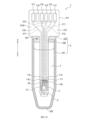
- the ion sensor 1 of the third embodiment has the form shown in FIG.
- the container 9 has a body portion 301 and a lid 303 .
- the main body portion 301 has a bottomed tubular shape with a bottom portion 305 .
- the body portion 301 has an opening portion 307 on the side opposite to the bottom portion 305 . Note that the direction from the bottom 305 to the opening 307 is the X direction. Let the direction opposite to the X direction be the Y direction.
- the lid 303 is a cylindrical member made of an elastic material such as rubber. Lid 303 is inserted into opening 307 . Opening 307 is closed by lid 303 . A notch 309 is formed in the lid 303 . The cut 309 penetrates the lid 303 in the thickness direction of the lid 303 . A solution 7 is accommodated in the container 9 .
- the ion sensor 1 includes an insertion member 311.
- the insertion member 311 includes a substrate 313 , a sensor section 3 , a reference electrode 5 , electrode sections 111 , 113 , 115 and 116 , a protrusion 130 , bonding wires 28 and a protection member 27 .
- the substrate 313 consists of a printed circuit board.
- the basic form of the substrate 313 is a band-like form extending along the X and Y directions.
- the substrate 313 has an X-side end portion 313X wider than other portions on the X-direction side. A portion of the substrate 313 excluding the X-side end portion 313X is inserted into the container 9 through the cut 309 .
- Sensor section 3 , reference electrode 5 , electrode sections 111 , 113 , 115 and 116 , projecting section 130 , bonding wire 28 , and protective member 27 are arranged near the end of substrate 313 on the bottom section 305 side. is provided.
- the sensor part 3, the reference electrode 5, the projecting part 130, the bonding wire 28, and the protective member 27 in the third embodiment are the same as those in the second embodiment.
- the electrode portions 111, 113, 115, and 116 in the third embodiment are the same as the electrode portions 111X, 113X, 115X, and 116X in the second embodiment.
- Electrode portions 411, 413, 415, 416, 417, and 418 are formed on the surface of the X-side end portion 313X. Each of the electrode portions 411, 413, 415, 416, 417, and 418 is a metal thin film. Each of the electrode portions 411, 413, 415, 416, 417, and 418 has a rectangular shape.
- inner layer wirings 511, 513, 515, 516, and 517 are provided inside the substrate 313.
- the inner layer wirings 511 , 513 , 515 , 516 , 517 are wirings passing through the inside of the substrate 313 .
- the electrode section 411 is electrically connected to the electrode section 111 by an inner layer wiring 511 .
- the electrode portion 413 is electrically connected to the electrode portion 113 by an inner layer wiring 513 .
- the electrode portion 415 is electrically connected to the electrode portion 115 by an inner layer wiring 515 .
- the electrode portion 416 is electrically connected to the electrode portion 116 through an inner layer wiring 516 .
- the electrode portion 417 is electrically connected to the reference electrode 5 through an inner layer wiring 517 .
- the electrode units 411, 413, 415, 416, and 417 can output the signal of the ion sensor 1 to an external device.
- the ion sensor 1 may be a sensor that detects target ions other than hydrogen ions. Also in this case, the effects (1A) to (1F) and (2A) to (2C) can be obtained.
- the material of the sensitive film of the ISFET can be a sensitive film corresponding to target ions to be detected.
- the reference electrode 5 may be an electrode other than the Ag/AgCl electrode.
- the reference electrode 5 may be, for example, a hydrogen electrode, a calomel electrode, or the like. Also in this case, the effects (1A) to (1F) and (2A) to (2C) can be obtained.
- the container 9 may have a structure that is not sealed.
- an inert gas may be continuously introduced into the container 9 by a gas introduction unit to create an inert gas atmosphere inside the container 9 .
- the gas introduction unit can be configured using a known pump or the like.
- the solution 7 may not contain chloride ions.
- the reference electrode 5 may be a conventional Ag/AgCl electrode. In this case also, the effects of (1A) to (1B), (1D) to (1F) and (2A) to (2C) can be obtained.
- the inert gas introduced into the container 9 may be gas other than nitrogen gas.
- gases other than nitrogen gas include argon gas.
- the label 107 may be something other than an enzyme.
- grooves 33 may be formed instead of the protrusions 30.
- FIG. The groove portion 33 is formed in the X-side surface 3A.
- the groove 33 is arranged to surround the sensing area 29 when viewed from the viewpoint PX.
- the protective member 27 is positioned outside the groove 33 when viewed from the viewpoint PX.
- a portion of groove 33 is provided in a portion between sensing area 29 and protection member 27 .
- the groove 33 has a recessed shape compared to the surrounding X-side surface 3A. Therefore, a step 32 is formed between the groove 33 and the surrounding X-side surface 3A.
- the above effect (1E) can be obtained.
- the projecting portion 30 may be formed in two layers. In this case, the effect of (1E) above is even more remarkable.
- the groove portion 33 may be formed double. In this case, the effect of (1E) above is even more remarkable. Note that the viewpoint PX shown in FIG. 7A is omitted from FIGS. 7B and 7C.
- grooves may be formed instead of the protrusions 130 .
- the projecting portion 130 may be formed in two layers, and the groove portion may be formed in two layers.
- the sensor unit 3 may include sensors other than the ISFET. Sensors other than ISFET include, for example, pH glass electrodes.
- the substance to be detected may be a virus other than SARS-CoV-2, a cell, or a molecule such as a protein.
- the mounting of the ion sensor 1 is not limited to wire bonding.
- the mounting of the ion sensor 1 may be, for example, a combination of flip chip and underfill agent.
- the mounting of the ion sensor 1 may be WLP (Wafer level Packaging).
- signal communication is not limited to wired.
- Signal communication may be, for example, wireless communication such as NFC (Near field communication).
- an ion sensor system may be configured.
- the sensor unit 3 may be a chip on which a plurality of sensors are arranged.
- the multiple sensors include, for example, temperature sensors.
- the ion sensor 1 may include a sensor separate from the sensor section 3 in the solution 7.
- One or both of the sensor section 3 and the reference electrode 5 may be stored in the solution 7, then dried, and then reused.
- the ion sensor 1 may further include a signal processing circuit.
- the signal processing circuit and the sensor section 3 can be integrated.
- the ion sensor 1 may estimate or correct the drift signal of the sensor section 3 by signal processing.
- the ion sensor 1 may include a substance insoluble in the solution 7 in the container 9 instead of the inert gas.
- examples of substances that do not dissolve in the solution 7 include oil and the like.
- the treatment performed before introducing the substance to be detected into the solution 7 is pretreatment.
- pretreatment for example, there is a treatment of binding the fusion substance 103 to the substance to be detected.
- Pretreatment can be performed, for example, by pipetting by a human, automated treatment by a robot, treatment using a microchannel, or the like.
- a plurality of functions possessed by one component in the above embodiment may be realized by a plurality of components, or a function possessed by one component may be realized by a plurality of components. good too. Moreover, a plurality of functions possessed by a plurality of components may be realized by one component, or one function realized by a plurality of components may be realized by one component. Also, part of the configuration of the above embodiment may be omitted. Also, at least part of the configuration of the above embodiment may be added or replaced with respect to the configuration of the other above embodiment.
- the present disclosure can also be implemented in various forms such as a system including the ion sensor 1 as a component.
- a system including the ion sensor 1 as a component.
- [Technical concept disclosed in this specification] [Item 1] an ion detection element (3); a reference electrode (5) providing a reference point for the potential; a solution (7) whose ion concentration can be changed in the sensing area (29) of the ion detection element; with wherein the sensing area of the ion detection element is placed in the solution; an ion sensor (1); [Item 2] The ion sensor according to item 1, and at least a portion of said reference electrode is disposed within said solution. ion sensor.
- the ion sensor according to item 1 or 2 contains ions necessary for oxidation-reduction reactions of the reference electrode; ion sensor.
- the ion sensor according to item 5 The reference electrode is provided on the surface of the base material, The ion detecting element is positioned between the reference electrode and the electrode section, The reference electrode is larger than the electrode portion, ion sensor.
- a detection method for a substance to be detected (101) using an ion sensor (1) The ion sensor is an ion detection element (3); a reference electrode (5) providing a reference point for the potential; A solution (7) whose ion concentration can be changed in the sensing area (29) of the ion detection element, the sensing area of the ion detection element is disposed in the solution; introducing the substance to be detected bound to a label (107) having a function of changing the amount of ions detectable by the ion sensor into the solution; using the ion sensor to detect changes in the amount of ions according to the concentration of the label; A method for detecting a substance to be detected.
Landscapes
- Life Sciences & Earth Sciences (AREA)
- Chemical & Material Sciences (AREA)
- Health & Medical Sciences (AREA)
- Physics & Mathematics (AREA)
- Molecular Biology (AREA)
- Chemical Kinetics & Catalysis (AREA)
- Electrochemistry (AREA)
- Analytical Chemistry (AREA)
- Biochemistry (AREA)
- General Health & Medical Sciences (AREA)
- General Physics & Mathematics (AREA)
- Immunology (AREA)
- Pathology (AREA)
- Microelectronics & Electronic Packaging (AREA)
- Engineering & Computer Science (AREA)
- Investigating Or Analyzing Materials By The Use Of Electric Means (AREA)
Priority Applications (4)
| Application Number | Priority Date | Filing Date | Title |
|---|---|---|---|
| CN202280061670.7A CN117999476A (zh) | 2021-09-16 | 2022-08-30 | 离子传感器、以及被检测物质的检测方法 |
| JP2023548393A JP7666616B2 (ja) | 2021-09-16 | 2022-08-30 | イオンセンサ、及び被検出物質の検出方法 |
| DE112022004441.1T DE112022004441T5 (de) | 2021-09-16 | 2022-08-30 | Ionensensor und Verfahren zur Erfassung von zu erfassender Substanz |
| US18/603,999 US20240241078A1 (en) | 2021-09-16 | 2024-03-13 | Ion sensor and method for detecting substance being detected |
Applications Claiming Priority (2)
| Application Number | Priority Date | Filing Date | Title |
|---|---|---|---|
| JP2021151177 | 2021-09-16 | ||
| JP2021-151177 | 2021-09-16 |
Related Child Applications (1)
| Application Number | Title | Priority Date | Filing Date |
|---|---|---|---|
| US18/603,999 Continuation US20240241078A1 (en) | 2021-09-16 | 2024-03-13 | Ion sensor and method for detecting substance being detected |
Publications (1)
| Publication Number | Publication Date |
|---|---|
| WO2023042657A1 true WO2023042657A1 (ja) | 2023-03-23 |
Family
ID=85602173
Family Applications (1)
| Application Number | Title | Priority Date | Filing Date |
|---|---|---|---|
| PCT/JP2022/032626 Ceased WO2023042657A1 (ja) | 2021-09-16 | 2022-08-30 | イオンセンサ、及び被検出物質の検出方法 |
Country Status (5)
| Country | Link |
|---|---|
| US (1) | US20240241078A1 (https=) |
| JP (1) | JP7666616B2 (https=) |
| CN (1) | CN117999476A (https=) |
| DE (1) | DE112022004441T5 (https=) |
| WO (1) | WO2023042657A1 (https=) |
Cited By (1)
| Publication number | Priority date | Publication date | Assignee | Title |
|---|---|---|---|---|
| WO2025187754A1 (ja) * | 2024-03-06 | 2025-09-12 | 株式会社デンソー | 検知器、検知装置、及び検知方法 |
Citations (6)
| Publication number | Priority date | Publication date | Assignee | Title |
|---|---|---|---|---|
| JPS6459058A (en) * | 1987-08-31 | 1989-03-06 | Nec Corp | Enzyme immune sensor and enzyme immunoassay using said sensor |
| JPH01282456A (ja) * | 1988-05-09 | 1989-11-14 | Taiyo Yuden Co Ltd | イオンセンサの検体滴下用電極部品 |
| JP2000510233A (ja) * | 1996-04-25 | 2000-08-08 | ペンス,インコーポレイテッド | バイオセンサ装置および方法 |
| JP2014115125A (ja) * | 2012-12-07 | 2014-06-26 | Hitachi High-Technologies Corp | 生体分子計測装置および生体分子の計測方法 |
| JP2015190848A (ja) * | 2014-03-28 | 2015-11-02 | Nltテクノロジー株式会社 | Tftイオンセンサ並びにこれを用いた測定方法及びtftイオンセンサ機器 |
| US20150330941A1 (en) * | 2014-05-13 | 2015-11-19 | Arizona Board Of Regents On Behalf Of Arizona State University | System and Method for Ion-Selective, Field Effect Transistor on Flexible Substrate |
Family Cites Families (7)
| Publication number | Priority date | Publication date | Assignee | Title |
|---|---|---|---|---|
| JP2005106587A (ja) | 2003-09-30 | 2005-04-21 | Horiba Biotechnology Co Ltd | 抗原抗体反応を用いた分析方法および装置 |
| JP4331181B2 (ja) | 2006-03-30 | 2009-09-16 | 株式会社日立製作所 | 測定装置及び分析用素子 |
| JP6360294B2 (ja) | 2013-11-19 | 2018-07-18 | 大日本印刷株式会社 | 溶液内蔵バイオセンサ |
| US20190018004A1 (en) | 2017-07-12 | 2019-01-17 | Robert Bosch Gmbh | System and Method for Single-Step ELISA via Local pH Modulation |
| JP2019028071A (ja) | 2017-07-27 | 2019-02-21 | 国立研究開発法人産業技術総合研究所 | 生体分子濃度の電気化学的測定方法 |
| JP7212885B2 (ja) | 2019-03-01 | 2023-01-26 | 株式会社デンソー | 複合体、及び計測方法 |
| CN111193224B (zh) | 2020-03-13 | 2020-11-06 | 山东合力金桥系统集成技术有限公司 | 一种信息交互数据线的安装设备 |
-
2022
- 2022-08-30 WO PCT/JP2022/032626 patent/WO2023042657A1/ja not_active Ceased
- 2022-08-30 CN CN202280061670.7A patent/CN117999476A/zh active Pending
- 2022-08-30 JP JP2023548393A patent/JP7666616B2/ja active Active
- 2022-08-30 DE DE112022004441.1T patent/DE112022004441T5/de active Pending
-
2024
- 2024-03-13 US US18/603,999 patent/US20240241078A1/en active Pending
Patent Citations (6)
| Publication number | Priority date | Publication date | Assignee | Title |
|---|---|---|---|---|
| JPS6459058A (en) * | 1987-08-31 | 1989-03-06 | Nec Corp | Enzyme immune sensor and enzyme immunoassay using said sensor |
| JPH01282456A (ja) * | 1988-05-09 | 1989-11-14 | Taiyo Yuden Co Ltd | イオンセンサの検体滴下用電極部品 |
| JP2000510233A (ja) * | 1996-04-25 | 2000-08-08 | ペンス,インコーポレイテッド | バイオセンサ装置および方法 |
| JP2014115125A (ja) * | 2012-12-07 | 2014-06-26 | Hitachi High-Technologies Corp | 生体分子計測装置および生体分子の計測方法 |
| JP2015190848A (ja) * | 2014-03-28 | 2015-11-02 | Nltテクノロジー株式会社 | Tftイオンセンサ並びにこれを用いた測定方法及びtftイオンセンサ機器 |
| US20150330941A1 (en) * | 2014-05-13 | 2015-11-19 | Arizona Board Of Regents On Behalf Of Arizona State University | System and Method for Ion-Selective, Field Effect Transistor on Flexible Substrate |
Non-Patent Citations (2)
| Title |
|---|
| BOUSSE L. J., BERGVELD P., GEEREADTS H. J. M.: "PROPERTIES OF AG/AGCL ELECTRODES FABRICATED WITH IC-COMPATIBLE TECHNOLOGIES.", SENSORS AND ACTUATORS., ELSEVIER SEQUOIA S.A. LAUSANNE., CH, vol. 09., no. 03., 1 May 1986 (1986-05-01), CH , pages 179 - 197., XP000615121, DOI: 10.1016/0250-6874(86)80020-8 * |
| JENNIFER R. MCKENZIE, ANDREW C. COGNATA, ANNA N. DAVIS, JOHN P. WIKSWO, DAVID E. CLIFFEL: "Real-Time Monitoring of Cellular Bioenergetics with a Multianalyte Screen-Printed Electrode", ANALYTICAL CHEMISTRY, AMERICAN CHEMICAL SOCIETY, US, vol. 87, no. 15, 4 August 2015 (2015-08-04), US , pages 7857 - 7864, XP055498366, ISSN: 0003-2700, DOI: 10.1021/acs.analchem.5b01533 * |
Cited By (1)
| Publication number | Priority date | Publication date | Assignee | Title |
|---|---|---|---|---|
| WO2025187754A1 (ja) * | 2024-03-06 | 2025-09-12 | 株式会社デンソー | 検知器、検知装置、及び検知方法 |
Also Published As
| Publication number | Publication date |
|---|---|
| US20240241078A1 (en) | 2024-07-18 |
| JP7666616B2 (ja) | 2025-04-22 |
| CN117999476A (zh) | 2024-05-07 |
| DE112022004441T5 (de) | 2024-07-25 |
| JPWO2023042657A1 (https=) | 2023-03-23 |
Similar Documents
| Publication | Publication Date | Title |
|---|---|---|
| Barbirz et al. | Mass spectrometry unravels disulfide bond formation as the mechanism that activates a molecular chaperone | |
| Brookes et al. | High throughput two‐dimensional blue‐native electrophoresis: A tool for functional proteomics of mitochondria and signaling complexes | |
| Sloane et al. | High throughput peptide mass fingerprinting and protein macroarray analysis using chemical printing strategies | |
| CN1602422B (zh) | 标记样品分子的方法及组合物 | |
| US20120309024A1 (en) | Electrophoretically Enhanced Detection of Analytes on a Solid Support | |
| Neves et al. | Multiplexed electrochemical immunosensor for detection of celiac disease serological markers | |
| EP1574848A1 (en) | Biosensor | |
| Katayama et al. | Efficient in‐gel digestion procedure using 5‐cyclohexyl‐1‐pentyl‐β‐D‐Maltoside as an additive for gel‐based membrane proteomics | |
| Kecskemeti et al. | Preparation and characterization of a packed bead immobilized trypsin reactor integrated into a PDMS microfluidic chip for rapid protein digestion | |
| JP4892686B2 (ja) | 酵素センサ、該酵素センサを使用した分析方法及びキット | |
| JP7666616B2 (ja) | イオンセンサ、及び被検出物質の検出方法 | |
| Khalilpour et al. | Proteomic-based biomarker discovery for development of next generation diagnostics | |
| Pal et al. | Direct interaction between a precursor mature domain and transport component Tha4 during twin arginine transport of chloroplasts | |
| AU2005252853B2 (en) | Method | |
| Bradd et al. | Analysis of membrane proteins by western blotting and enhanced chemiluminescence | |
| WO2012090960A1 (ja) | 検体検出用チップ、それを用いたセンサ、及び検体検出方法 | |
| Ramirez et al. | Immuno‐Spin Trapping: Detection of Protein‐Centered Radicals | |
| Streaker et al. | Nonenzymatic biotinylation of a biotin carboxyl carrier protein: unusual reactivity of the physiological target lysine | |
| Lee et al. | Sulfhydryl-specific probe for monitoring protein redox sensitivity | |
| JP4956715B2 (ja) | 目的物質の測定方法 | |
| CN105823871B (zh) | 一种高效稳定的单组份酶联免疫显色液及其制备方法 | |
| WO2005015217A1 (ja) | 測定対象物測定器具、測定装置および測定方法 | |
| Fu et al. | Native detection of protein O-GlcNAcylation by gel electrophoresis | |
| Tia et al. | Protein post-translational modification analyses using on-chip immunoprobed isoelectric focusing | |
| Otto | Immunoblotting |
Legal Events
| Date | Code | Title | Description |
|---|---|---|---|
| 121 | Ep: the epo has been informed by wipo that ep was designated in this application |
Ref document number: 22869804 Country of ref document: EP Kind code of ref document: A1 |
|
| WWE | Wipo information: entry into national phase |
Ref document number: 2023548393 Country of ref document: JP |
|
| WWE | Wipo information: entry into national phase |
Ref document number: 202280061670.7 Country of ref document: CN |
|
| WWE | Wipo information: entry into national phase |
Ref document number: 112022004441 Country of ref document: DE |
|
| 122 | Ep: pct application non-entry in european phase |
Ref document number: 22869804 Country of ref document: EP Kind code of ref document: A1 |