WO2023042238A1 - 画像生成システム、画像生成方法、及び、記録媒体 - Google Patents
画像生成システム、画像生成方法、及び、記録媒体 Download PDFInfo
- Publication number
- WO2023042238A1 WO2023042238A1 PCT/JP2021/033624 JP2021033624W WO2023042238A1 WO 2023042238 A1 WO2023042238 A1 WO 2023042238A1 JP 2021033624 W JP2021033624 W JP 2021033624W WO 2023042238 A1 WO2023042238 A1 WO 2023042238A1
- Authority
- WO
- WIPO (PCT)
- Prior art keywords
- road
- deterioration
- image
- degree
- predicted
- Prior art date
- Legal status (The legal status is an assumption and is not a legal conclusion. Google has not performed a legal analysis and makes no representation as to the accuracy of the status listed.)
- Ceased
Links
Images



Classifications
-
- G—PHYSICS
- G06—COMPUTING OR CALCULATING; COUNTING
- G06V—IMAGE OR VIDEO RECOGNITION OR UNDERSTANDING
- G06V20/00—Scenes; Scene-specific elements
- G06V20/50—Context or environment of the image
- G06V20/56—Context or environment of the image exterior to a vehicle by using sensors mounted on the vehicle
- G06V20/588—Recognition of the road, e.g. of lane markings; Recognition of the vehicle driving pattern in relation to the road
-
- G—PHYSICS
- G06—COMPUTING OR CALCULATING; COUNTING
- G06T—IMAGE DATA PROCESSING OR GENERATION, IN GENERAL
- G06T1/00—General purpose image data processing
-
- G—PHYSICS
- G06—COMPUTING OR CALCULATING; COUNTING
- G06T—IMAGE DATA PROCESSING OR GENERATION, IN GENERAL
- G06T7/00—Image analysis
-
- G—PHYSICS
- G06—COMPUTING OR CALCULATING; COUNTING
- G06T—IMAGE DATA PROCESSING OR GENERATION, IN GENERAL
- G06T7/00—Image analysis
- G06T7/0002—Inspection of images, e.g. flaw detection
-
- G—PHYSICS
- G06—COMPUTING OR CALCULATING; COUNTING
- G06V—IMAGE OR VIDEO RECOGNITION OR UNDERSTANDING
- G06V20/00—Scenes; Scene-specific elements
- G06V20/50—Context or environment of the image
- G06V20/56—Context or environment of the image exterior to a vehicle by using sensors mounted on the vehicle
-
- G—PHYSICS
- G06—COMPUTING OR CALCULATING; COUNTING
- G06T—IMAGE DATA PROCESSING OR GENERATION, IN GENERAL
- G06T2207/00—Indexing scheme for image analysis or image enhancement
- G06T2207/20—Special algorithmic details
- G06T2207/20081—Training; Learning
-
- G—PHYSICS
- G06—COMPUTING OR CALCULATING; COUNTING
- G06T—IMAGE DATA PROCESSING OR GENERATION, IN GENERAL
- G06T2207/00—Indexing scheme for image analysis or image enhancement
- G06T2207/20—Special algorithmic details
- G06T2207/20212—Image combination
- G06T2207/20221—Image fusion; Image merging
Definitions
- the present disclosure relates to a road image generation system and the like.
- Roads deteriorate over time.
- the degree of deterioration of roads is represented by numerical values such as crack rate, flatness, and pavement maintenance control index (MCI).
- Road repairs are planned based on these numbers and the past or present appearance of the road.
- Patent Document 1 discloses a structure inspection support system that analyzes the state of deterioration of structures and generates data on predicted values for the degree of future deterioration.
- the purpose of the present disclosure is to provide an image generation system and the like that can express the future degree of deterioration of roads in an easy-to-understand manner.
- An image generation system includes acquisition means for acquiring a road image obtained by imaging a road, deterioration level determination means for determining a future deterioration level of the road, and based on the road image, according to the deterioration level, and generating means for generating a prediction image representing the road deterioration on the road.
- An image generation method acquires a road image of a road, determines a future degree of deterioration of the road, and expresses road deterioration corresponding to the degree of deterioration on the road based on the road image. generate a predicted image.
- a program acquires a road image of a road, determines a future degree of deterioration of the road, and predicts the road deterioration according to the degree of deterioration based on the road image. Make a computer perform a process that generates an image.
- the degree of future deterioration of roads can be expressed in an easy-to-understand manner.
- FIG. 1 is a block diagram showing a configuration example of an image generation system 100;
- FIG. 4 is a flow chart showing an example of the operation of the image generation system 100; It is a figure which shows the example of a road image. It is a figure which shows the example of the screen which receives the input of a deterioration degree.
- FIG. 10 is a diagram showing an example of a predicted image;
- FIG. 11 is an image showing another example of a display screen of a predicted image;
- FIG. FIG. 11 is an image showing an example of a screen for accepting selection of a predicted image to be displayed;
- FIG. 5 is a block diagram showing an example of the hardware configuration of computer 500.
- FIG. 10 is a diagram showing an example of a predicted image
- FIG. 11 is an image showing another example of a display screen of a predicted image
- FIG. FIG. 11 is an image showing an example of a screen for accepting selection of a predicted image to be displayed
- FIG. 5 is a block diagram showing an example of
- Road deterioration is the deterioration that occurs on paved roads due to factors such as vehicle traffic and rainfall.
- Road deterioration is classified into several types including, for example, cracks, potholes, rutting, and road unevenness.
- Cracks may be classified into different types, linear cracks and tortoiseshell cracks, depending on their shape.
- a straight crack is a single linear crack.
- a tortoiseshell crack is a tortoiseshell-shaped crack that occurs, for example, when vertical and horizontal straight cracks are connected.
- Road cracks develop into straight cracks, tortoiseshell cracks, and potholes.
- the degree of road deterioration is represented by the degree of deterioration.
- the degree of deterioration may be any index including degree of cracking, number of potholes, size of potholes, amount of rutting, or flatness.
- the degree of deterioration may be determined based on a combination of a plurality of indicators representing the degree of road deterioration.
- the degree of cracking is represented by the shape, length, area, number of cracks, or a combination thereof.
- Crack rate is an example of crack degree.
- the crack ratio is represented by, for example, 100 ⁇ (crack area/road section area). In this case, the value of the degree of deterioration ranges from 0% to 100%.
- the crack area is calculated by any method. Note that the method for calculating the crack rate is not particularly limited, and other known calculation methods can be applied.
- the size of a pothole is represented by, for example, the area, width, length, or depth of the pothole, or a combination of these.
- the amount of rutting is the depth of the rut where the running track of the vehicle is lower than other road surfaces due to the load of the vehicle and the friction with the tires.
- the degree of cracking, the number and size of potholes, and the amount of rutting may be calculated based on measurement data obtained by measuring the road surface with a sensor. Alternatively, these indexes may be calculated based on the recognition result of recognizing road deterioration from an image of the road.
- the IRI is an index that associates the road surface with the ride comfort of the driver, and expresses the degree of unevenness as a numerical value.
- the IRI may be calculated based on measurement data obtained by measuring the road surface with a sensor.
- the IRI may be calculated based on the value of an acceleration sensor attached to the vehicle while the vehicle is running.
- the IRI is calculated based on the vertical acceleration value included in the acceleration acquired at the detection position. Note that the method for calculating the IRI is not limited to the above, and a known calculation method can be employed.
- the degree of deterioration is not limited to the above indexes, and any index representing road deterioration, including MCI (Maintenance Control Index), for example, may be used.
- MCI Maintenance Control Index
- the value of MCI is the minimum result of calculating four defining equations using crack rate, rut depth, and flatness. MCI decreases as the road deteriorates.
- the crack ratio is mainly used as the degree of deterioration. Therefore, the value of the degree of deterioration increases as the degree of deterioration worsens. It should be noted that the method of representing the degree of deterioration is not limited to this, and for example, the value of the degree of deterioration may be made smaller when the deterioration has occurred.
- An image generation system generates a prediction image representing road deterioration that is predicted to occur on a certain road in the future.
- a predicted image generated by the road image generation system represents the state of the road at a certain degree of deterioration.
- FIG. 1 is a block diagram showing a configuration example of an image generation system 100 according to one embodiment.
- the image generation system 100 includes an acquisition unit 101 , a deterioration degree determination unit 102 and a generation unit 103 .
- the acquisition unit 101 acquires a road image of the road.
- the road image may be captured by an in-vehicle camera such as a drive recorder.
- the type of camera is not limited to this, and various types of cameras may be used.
- the road image may be captured by a camera mounted on a bicycle, a drone, or other mobile object, a camera carried by a person, or a fixed camera installed on the road.
- the road image may be taken by a person or automatically.
- the road image taken by the camera may be stored in a database (not shown). At this time, the acquisition unit 101 may acquire the road image from the database. Alternatively, if the image generation system 100 is connected to an arbitrary camera by wire or wirelessly, the acquisition unit 101 may acquire road images from the camera.
- the acquisition unit 101 may acquire the date and time when the road image was taken together with the road image.
- the acquisition unit 101 may acquire information on the position where the road image was captured together with the road image.
- the position information includes, for example, position information on a map, latitude and longitude, GNSS (Global Navigation Satellite System), or GPS (Global Positioning System) position information.
- the current or past state of the road is determined.
- the road image may or may not include road deterioration such as cracks.
- the imaging range of the road image is not particularly limited, and the road image may include objects other than the road. If the image contains objects other than the road, the location or size of the road degradation may become more noticeable.
- the acquisition unit 101 may acquire the pavement material of the photographed road or the current degree of deterioration of the road. For example, the acquisition unit 101 may recognize the pavement material and the current degree of deterioration from the road image. The acquiring unit 101 may transmit the recognized material and the degree of deterioration to the degree of deterioration determining unit 102 .
- the deterioration degree determination unit 102 determines the future deterioration degree of the road from which the road image was acquired. Specifically, the deterioration degree determination unit 102 determines the deterioration degree of the image generated by the generation unit 103 . The deterioration degree determination unit 102 determines, for example, a crack rate as the deterioration degree.
- the deterioration degree determination unit 102 may determine the deterioration degree received from the user as the future deterioration degree.
- the user inputs the degree of deterioration using, for example, an input device connected to the image generation system 100 .
- Input devices are, for example, a mouse, a keyboard, and a touch panel display.
- the deterioration degree determination unit 102 may determine the predicted deterioration degree as the future deterioration degree.
- the deterioration degree determination unit 102 predicts, for example, the deterioration degree on the prediction target day.
- An arbitrary time point after the time the road image was captured is set as the prediction target date.
- the prediction target date is set after, for example, the point in time when the deterioration degree determination unit 102 makes the prediction, but the date is not limited to this.
- the deterioration degree determination unit 102 may predict the deterioration degree on the prediction target date specified by the user.
- the prediction of the degree of deterioration may be performed by another device.
- Other devices predict the degree of deterioration on the prediction target date and transmit the degree of deterioration to the image generation system 100 .
- the deterioration degree determination unit 102 acquires the deterioration degree from the other device and determines the predicted deterioration degree as the future deterioration degree.
- Any method including known methods is used for the method of predicting the degree of deterioration. Examples of prediction methods will be described later.
- the generating unit 103 Based on the road image, the generating unit 103 generates a predicted image representing road deterioration according to the degree of deterioration determined by the deterioration degree determining unit 102 on the photographed road.
- a predictive image representing future road deterioration is presented for a photographed road, it is easier to imagine the future state of the road than when the degree of deterioration is presented as a value. The image generation method will be described later.
- the deterioration degree determination unit 102 may determine the deterioration degrees at a plurality of points in the future.
- the generation unit 103 may generate a plurality of predicted images representing the road deterioration corresponding to the degree of deterioration at a plurality of points in time. Specifically, for example, the deterioration degree determination unit 102 determines the deterioration degree of the road 6 months, 12 months, and 18 months after the road image was captured. At this time, the generating unit 103 generates three predicted images representing respective degrees of deterioration.
- FIG. 2 is a flow chart showing an example of the operation of the image generation system 100 according to one embodiment.
- the acquisition unit 101 acquires a road image (step S01).
- the acquisition unit 101 may acquire the road image based on the user's designation.
- the acquisition unit 101 may acquire a road image of a point designated by the user.
- FIG. 3 is a diagram showing an example of a road image.
- FIG. 3 is an image of a road on which cars run.
- FIG. 3 is taken, for example, by a camera mounted on a vehicle running in the left lane. In this example, the camera shoots forward in the direction of travel.
- the road in FIG. 3 has a crack on the left edge of the road.
- the road image in FIG. 3 includes sidewalks on both sides of the road.
- the imaging range of the road image is not limited to the range shown in FIG.
- the imaging range may be narrow or wide, for example, in the vertical or horizontal direction.
- the deterioration degree determination unit 102 determines the future deterioration degree (step S02).
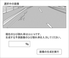
- FIG. 4 is a diagram showing an example of a screen for receiving an input of the degree of deterioration from the user.
- the screen of FIG. 4 includes the acquired road image and the degree of deterioration of the road image.
- the user enters a numerical value into an input field for crack rate, for example.
- the method of inputting the degree of deterioration is not limited to inputting into the input field.
- the degree of deterioration may be entered using either a pull-down list, check box, or radio button. When the user presses the "execute image generation" button, the deterioration level determination unit 102 determines the received deterioration level as the deterioration level of the predicted image.
- the generating unit 103 acquires the degree of deterioration from the degree of deterioration determining unit 102 .
- the generation unit 103 generates a predicted image representing road deterioration corresponding to the determined degree of deterioration on the imaged road based on the acquired road image (step S03).
- FIG. 5 is a diagram showing an example of a predicted image to be generated.
- the predicted image of FIG. 5 has more cracks than the road image of FIG. Also, some cracks are longer and thicker than in the road image.
- the deterioration degree determination unit 102 may predict the deterioration degree by any of the following methods. However, the prediction method is not limited to the following example.
- the prediction unit may combine a plurality of methods to predict the degree of deterioration.
- the deterioration degree determining unit 102 may predict the degree of deterioration by giving parameters related to the road to the prediction formula.
- Parameters related to roads are parameters that affect the degree of deterioration.
- the road-related parameters represent characteristics of the environment of the road or characteristics of the road.
- the deterioration degree determination unit 102 acquires parameters related to roads for prediction. For example, the deterioration degree determining unit 102 may acquire parameters input by the user. Further, the deterioration degree determination unit 102 may acquire parameters from the acquisition unit 101 .
- Parameters related to roads may be stored in the database for each road.
- the deterioration degree determination unit 102 acquires, for example, identification information of a road whose deterioration degree is to be predicted. Next, the deterioration degree determination unit 102 acquires parameters corresponding to the identification information of the road from the database. Alternatively, the parameters may be stored in association with road images. In this case, the deterioration degree determination unit 102 acquires parameters corresponding to the road image.
- the parameters relating to the road include parameters representing characteristics of the environment of the road and parameters representing characteristics of the road. Parameters characterizing the road environment include traffic volume, weather information, and area information. The parameters representing road characteristics include road construction information. Note that the parameters are not limited to these, and other parameters may be included.
- Traffic volume is the amount of vehicles traveling on the road. Roads with heavy traffic deteriorate quickly. Traffic may include the amount of heavy vehicles traveling on roads. Roads on which many heavy vehicles travel deteriorate quickly.
- Weather information is, for example, the amount of precipitation, amount of snow, or temperature. The regional information includes whether or not the region is in a region where road deterioration progresses rapidly. For example, areas with high rainfall, areas near the coast, and cold areas experience rapid deterioration of roads.
- Construction information is, for example, pavement material, roadbed condition, layer thickness, or construction history.
- Pavement materials are, for example, asphalt and concrete. Asphalt generally deteriorates faster than concrete.
- the construction history includes, for example, when the road was paved or whether or not there was private construction. Deterioration progresses with the passage of time from when the road was paved. In addition, deterioration progresses when private use work is carried out.
- the deterioration degree determination unit 102 may predict the future deterioration degree based on, for example, the progress speed of road deterioration.
- the progress speed of road deterioration indicates changes in the degree of deterioration per unit time.
- the deterioration degree determining unit 102 calculates the future deterioration degree by applying the deterioration degree in the road image and the progress speed of the road deterioration to the prediction formula. It should be noted that the deterioration degree determining unit 102 may predict the deterioration degree in consideration of changes in progress speed per unit time.
- the deterioration degree determination unit 102 may predict the degree of deterioration in consideration of the fact that road deterioration progresses at different speeds depending on the road.
- the progress speed of road deterioration may be determined based on the parameters related to the road.
- the rate of progress of road deterioration for each road may be stored in a database.
- the deterioration degree determining unit 102 may acquire the traveling speed of the road on which the prediction is to be performed from the database. Note that the speed at which road deterioration progresses may be uniformly set to the same speed for all roads.
- the speed at which road deterioration progresses is included as an example of road-related parameters.
- the deterioration degree determining unit 102 may calculate the speed of progress of the road whose degree of deterioration is to be predicted based on the degree of deterioration at a plurality of times in the past.
- the deterioration degree determining unit 102 may acquire past deterioration degrees from a database.
- the deterioration degree determination unit 102 may acquire an image of the road captured in the past, and detect the past deterioration degree from the acquired image.
- the deterioration degree determination unit 102 detects, for example, road cracks, potholes, or ruts from past images.
- the deterioration degree determination unit 102 determines the position of the crack, the shape of the crack (line, tortoise shell), the length or area of the crack, the number of cracks, the position of the pothole, the area of the pothole, the number of potholes, or rutting. Detect quantity.
- the degree-of-degradation determination unit 102 calculates the amount of change in the degree of deterioration from the detected past degree of deterioration.
- the generation unit 103 may generate a predicted image by adding a figure representing road deterioration to the road image based on the determined degree of deterioration. For example, the generator 103 first recognizes the road portion of the original road image. Then, the generation unit 103 superimposes the figure on the road portion of the road image. For example, a line is superimposed as a figure representing a crack.
- the generation unit 103 may generate the predicted image by considering the position of the road deterioration portion of the original image. Specifically, for example, the generation unit 103 recognizes the crack portion. Next, the generation unit 103 increases cracks in the vicinity of the cracks or extends the recognized cracks. In this way, the generation unit 103 can generate a predicted image in which the road deterioration indicated by the original road image has progressed.
- the generation unit 103 may further use images related to other roads in addition to road images to generate predicted images.
- another image is called a stored image because it is stored in an arbitrary database.
- the stored image represents road deterioration of a road with a predetermined degree of deterioration.
- the database associates and stores the stored image with the degree of deterioration of the road.
- the generation unit 103 generates a predicted image by, for example, synthesizing the road image acquired by the acquisition unit 101 and the stored image corresponding to the determined degree of deterioration.
- a stored image corresponding to the determined degree of deterioration includes a stored image representing the same degree of deterioration as the determined degree of deterioration.
- the stored image corresponding to the determined degree of deterioration may include a stored image representing a degree of deterioration within a predetermined range from the determined degree of deterioration.
- the stored image may be an image of another road.
- the imaging range of the stored image may be the same as the road image, or may be wider or narrower than the road image imaging range.
- the imaging range of the stored image may be a portion of the road with road deterioration.
- the method of synthesizing the road image and the stored image is not particularly limited.
- the generator 103 may superimpose the stored image on the road image.
- the generation unit 103 may superimpose the road deterioration portion of the stored image on the road of the road image.
- the generation unit 103 may generate a predicted image by inputting the road image into a learning model generated by machine learning.
- a learning model for example, a Generative Adversarial Network (GAN) may be used.
- GAN Generative Adversarial Network
- Cycle-GAN or Pix2Pix may be used.
- the aforementioned stored images may be used to generate the learning model.
- the acquisition unit 101 acquires a road image of the road. Further, the deterioration degree determination unit 102 determines the future deterioration degree of the road from which the road image was acquired. Furthermore, the generation unit 103 generates a predicted image based on the road image. The predicted image represents the road deterioration corresponding to the degree of deterioration determined by the degree of deterioration determination unit 102 on the imaged road. Therefore, according to one embodiment, the future deterioration degree of the road can be expressed in an easy-to-understand manner.
- the generated predicted image can be used, for example, to determine the budget for road repair. Even if the degree of deterioration in the future is presented numerically, it is difficult for some people to understand the need for repair. By presenting the predicted image, the need for repair is understood, and the budget for repair is appropriately set.
- the image generation system 100 may further include a display control unit that displays the predicted image on a display (not shown).
- the display is, for example, a display connected to a computer or a tablet.
- An example of the display method of the predicted image will be described below. However, the display method of the predicted image is not limited to the following.
- the display control unit may display the predicted image and the road image side by side.
- the display control unit may display the determined degree of deterioration together with the predicted image.
- the display control unit may display the time associated with the predicted image together with the predicted image.
- the time related to the predicted image indicates the time predicted to be required for the progress of road deterioration from the degree of deterioration of the road image to the degree of deterioration of the predicted image.
- the time related to the prediction image can be displayed in any format such as the date of the prediction target date and the number of days, months, or years from the shooting date of the road image to the prediction target date.
- the display control unit may display a map indicating points corresponding to the displayed predicted image together with the predicted image.
- the display control unit may display the actually existing road deterioration and the predicted road deterioration included in the displayed predicted image so as to be identifiable.
- the display control unit displays, for example, real road deterioration and predicted road deterioration in different colors.
- the display control unit may display multiple predicted images for one point.
- the display control unit may display a plurality of predicted images on one screen so that the user can view them.
- the display control unit may switch the predicted images and display each predicted image one by one. According to such switching display, progress of road deterioration is represented like a fast-forward video of one point.
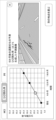
- the display control unit may display a graph representing changes in the degree of deterioration over time on the imaged road along with the predicted image.
- the generation unit 103 may generate a graph.
- the generating unit 103 acquires, for example, the degree of deterioration over time from the degree of deterioration determining unit 102 and plots it.
- the generation unit 103 passes the generated graph to the display control unit.
- FIG. 6 is an image showing another example of the display screen of the predicted image.
- FIG. 6 includes a graph representing crack rate versus time.
- the display control unit may display the correspondence relationship between the predicted image to be displayed and the position in the graph. For example, the plots on the graph corresponding to the predicted image to be displayed or the values on the axes may be displayed with more emphasis than other plots or values.
- the display control unit may switch and display predicted images for multiple points.
- the generation unit 103 may generate a predicted image for each of a plurality of road images obtained by imaging a plurality of continuous spots.
- the display control unit may, for example, switch and display predicted images for a plurality of continuous points. According to such switching display, a state of traveling on a road in the future is displayed.
- the display control unit described above may display a screen for accepting selection of a predicted image to be displayed from among the plurality of generated predicted images.
- the display control unit may switch the predicted image to be displayed according to an input from the user.
- the display control unit may, for example, display a screen for accepting an input of the prediction target date from the user.
- the prediction target date can be input in any format, such as the date of the prediction target date, or the number of days, months, or years from the road image shooting date to the prediction target date.
- the display control unit displays a prediction image corresponding to the input prediction target date.
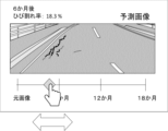
- FIG. 7 is an image showing an example of a screen for accepting selection of a predicted image to be displayed. According to the screen of FIG. 7, the user can select a prediction target date.
- the display control unit may display a slider bar and a slider, and switch the predicted image to be displayed based on the sliding of the position of the slider on the bar.
- the display control unit may display a screen for accepting the selection of the degree of deterioration from the user.
- the display control unit displays the predicted image of the selected degree of deterioration.
- the display control unit may switch the predicted image based on clicking a point on the graph in FIG. 6 or a value on the axis.
- the display control unit may display a screen for accepting designation as to which road the predicted image is to be displayed.
- the display control unit for example, displays a map and displays a predicted image for the selected road.
- the deterioration degree determination unit 102 may determine the type of road deterioration to be represented in the predicted image.
- the degree-of-degradation determining unit 102 may determine the type of road deterioration to be represented in the predicted image, out of linear cracks, tortoiseshell cracks, and potholes.
- the deterioration degree determination unit 102 may determine the type of road deterioration to be represented in the predicted image based on the type received from the user. Alternatively, the deterioration degree determining unit 102 may determine the predicted type of road deterioration as the type to be represented in the predicted image. The deterioration degree determination unit 102 may predict the type of road deterioration that will occur on the road in the future. Further, the deterioration degree determining unit 102 may determine the type of road deterioration predicted by another device as the type to be represented in the predicted image.
- the type of road deterioration can be predicted by any method.
- the deterioration degree determination unit 102 may predict the type of road deterioration based on the determined deterioration degree. Basically, the higher the degree of deterioration, the more the type of road deterioration that occurs on the road progresses to linear cracks, tortoiseshell cracks, and potholes. Therefore, when the crack rate is determined to be 70% or more, the deterioration degree determining unit 102 predicts that potholes and tortoise shell cracks will occur. may
- the deterioration degree determining unit 102 may calculate the probability of occurrence of each type of road deterioration based on parameters related to roads. For example, there is a high probability of potholes occurring on roads with heavy traffic and heavy rainfall. If the probability of occurrence of a pothole is greater than a predetermined criterion, the deterioration degree determining unit 102 predicts that a pothole will occur.
- the generation unit 103 may generate a predicted image representing the determined type of road deterioration.
- the generator 103 may, for example, draw the determined type of road deterioration on the road image.
- the generation unit 103 may combine the stored image and the road image according to the determined type of road deterioration.
- the stored image can be stored in the database in association with the type of road deterioration included in the image.
- the generating unit 103 may also use a learning model that generates a predicted image including the type of road deterioration for which the road image is determined.
- the generation unit 103 may generate the predicted image based on the pavement material of the road included in the road image. Roads look different depending on the pavement material. In addition, the progress of road deterioration may differ depending on the pavement material. Therefore, the stored image can be stored in the database in association with the degree of deterioration of the road and the material of the pavement.
- the generation unit 103 receives, for example, the pavement material of the road included in the road image from the acquisition unit 101 . Note that the generation unit 103 may receive an input of the pavement material from the user.
- the generating unit 103 changes the stored image used for generating the predicted image according to the determined pavement material.
- the generation unit 103 may generate the predicted image according to the weather when the road image was captured.
- Weather includes, for example, sunny, cloudy, and rainy.
- the road looks different depending on the weather. For example, on a cloudy day, the color of the road is darker than on a sunny day. On a rainy day, the road surface may get wet and puddles may form on the road surface. Therefore, for example, the generation unit 103 may generate a predicted image based on a stored image captured in the same weather as when the road image was captured.
- the stored image can be stored in the database in association with the degree of deterioration of the road and the weather at the time the stored image was taken.
- the generation unit 103 acquires, for example, the weather at the time the road image was captured from the acquisition unit 101 .
- the acquisition unit 101 may acquire the result of analyzing the weather at the time the road image was captured by analyzing the state of the sky or the state of the road surface indicated by the road image.
- the acquisition unit 101 may acquire the weather from a weather database based on the location and time when the road image was captured.
- the generating unit 103 may receive an input of the weather from the user when the road image is captured.
- each component of the image generation system 100 represents a functional unit block.
- a part or all of each component of each device may be realized by any combination of the computer 500 and a program.
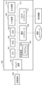
- FIG. 8 is a block diagram showing an example of the hardware configuration of computer 500.
- computer 500 includes, for example, CPU (Central Processing Unit) 501, ROM (Read Only Memory) 502, RAM (Random Access Memory) 503, program 504, storage device 505, drive device 507, communication interface 508 , an input device 509 , an input/output interface 511 and a bus 512 .
- CPU Central Processing Unit
- ROM Read Only Memory
- RAM Random Access Memory
- the program 504 includes instructions for realizing each function of each device.
- the program 504 is stored in advance in the ROM 502 , RAM 503 and storage device 505 .
- the CPU 501 implements each function of each device by executing instructions included in the program 504 .
- the functions of the image generation system 100 are realized by the CPU 501 of the image generation system 100 executing instructions included in the program 504 .
- the RAM 503 may store data processed in each function of each device.
- the RAM 503 of the computer 500 may store road images, stored images, or predicted images.
- the drive device 507 reads from and writes to the recording medium 506 .
- Communication interface 508 provides an interface with a communication network.
- the input device 509 is, for example, a mouse or a keyboard, and receives information input from the user.
- the output device 510 is, for example, a display, and outputs (displays) information to the user.
- the input/output interface 511 provides an interface with peripheral devices.
- a bus 512 connects each of these hardware components.
- the program 504 may be supplied to the CPU 501 via a communication network, or may be stored in the recording medium 506 in advance, read by the drive device 507 and supplied to the CPU 501 .
- FIG. 8 the hardware configuration shown in FIG. 8 is an example, and components other than these may be added, and some components may not be included.
- each device may be implemented by any combination of a computer and a program that are different for each component.
- a plurality of components included in each device may be realized by any combination of a single computer and a program.
- each component of each device may be realized by a general-purpose or dedicated circuit including a processor or the like, or a combination thereof. These circuits may be composed of a single chip, or may be composed of multiple chips connected via a bus. A part or all of each component of each device may be realized by a combination of the above-described circuits and the like and programs.
- each component of each device when a part or all of each component of each device is realized by a plurality of computers, circuits, etc., the plurality of computers, circuits, etc. may be centrally arranged or distributed.
- At least part of the image generation system 100 may be provided in SaaS (Software as a Service) format. That is, at least part of the functions for realizing image generation system 100 may be executed by software executed via a network.
- SaaS Software as a Service
- An image generation system comprising:
- Appendix 2 The image generating system according to appendix 1, wherein the predicted image is an image representing road deterioration such as cracks, potholes, rutting, and flatness anomaly.
- Appendix 3 3. The image generation system according to appendix 1 or 2, wherein the generating means generates the predicted image using a learning model.
- Appendix 4 4. The image generation system according to any one of appendices 1 to 3, wherein the generating means generates the predicted image by superimposing a graphic representing road deterioration on the road image.
- the generating means is Acquiring a stored image representing road deterioration of another road corresponding to the determined degree of deterioration; 5.
- the image generating system according to any one of appendices 1 to 4, wherein the predicted image is generated based on the acquired stored image and the road image.
- Appendix 6 The image generation system according to any one of Appendices 1 to 5, wherein the degree of deterioration is an index representing the degree of at least one of cracks, potholes, rutting, and flatness abnormalities.
- the deterioration degree determination means determines the type of road deterioration represented in the predicted image, 7.
- the image generating system according to any one of appendices 1 to 6, wherein the generating means generates the predicted image in which the determined type of road deterioration is expressed in the predicted image.
- Appendix 9 9. The image generation system according to any one of appendices 1 to 8, wherein the deterioration degree determination means determines the deterioration degree predicted based on the parameters related to the road as the future deterioration degree of the road.
- Appendix 10 10. The image generation system according to appendix 9, wherein the deterioration degree determination means determines the deterioration degree predicted based on the progress speed of road deterioration as the future deterioration degree of the road.
- Appendix 12 9. The image generation system according to any one of appendices 1 to 8, wherein the deterioration degree determination means determines the deterioration degree received from the user as the future deterioration degree of the road.
- Appendix 13 The image generation system according to any one of appendices 1 to 12, further comprising display control means for displaying the predicted image.
- the display control means controls, together with the predicted image, any of the degree of deterioration, a time predicted to be required for progress of road deterioration from the degree of deterioration of the road image to the degree of deterioration of the predicted image, and the road image. 14.
- the image generation system according to appendix 13.
- the deterioration degree determining means determines the deterioration degree at a plurality of points in the future,
- the generating means generates a plurality of predicted images representing road deterioration on the road corresponding to each of the degrees of deterioration at the plurality of points in time, 15.
- the image generation system according to appendix 13 or 14, wherein the display control means displays a plurality of the predicted images.
- the generating means further generates a graph representing the relationship between time and the degree of deterioration on the road,
- the display control means displays the graph, and displays correspondence between the displayed predicted image and the graph. 16.
- An image generation system according to any one of appendices 13-15.
- Appendix 17 17. The image generating system according to any one of appendices 13 to 16, wherein the display control means displays a screen for accepting selection of the predicted image to be displayed from among the plurality of predicted images.
- Appendix 18 18. The image generation system according to any one of appendices 13 to 17, wherein the display control means displays a map for receiving designation of the road on which the predicted image is to be displayed.
- [Appendix 19] Acquire a road image of the road, determining the future degree of deterioration of said road; generating, based on the road image, a predicted image representing road deterioration corresponding to the degree of deterioration on the road; Image generation method.
- [Appendix 20] Acquire a road image of the road, determining the future degree of deterioration of said road; generating, based on the road image, a predicted image representing road deterioration corresponding to the degree of deterioration on the road; A recording medium that non-temporarily records a program that causes a computer to execute a process.
Landscapes
- Engineering & Computer Science (AREA)
- Physics & Mathematics (AREA)
- General Physics & Mathematics (AREA)
- Theoretical Computer Science (AREA)
- Computer Vision & Pattern Recognition (AREA)
- Multimedia (AREA)
- Quality & Reliability (AREA)
- Image Processing (AREA)
- Road Repair (AREA)
- Traffic Control Systems (AREA)
Priority Applications (4)
| Application Number | Priority Date | Filing Date | Title |
|---|---|---|---|
| PCT/JP2021/033624 WO2023042238A1 (ja) | 2021-09-14 | 2021-09-14 | 画像生成システム、画像生成方法、及び、記録媒体 |
| JP2023547946A JP7758043B2 (ja) | 2021-09-14 | 2021-09-14 | 画像生成システム、画像生成方法、及び、プログラム |
| US18/687,452 US20240378900A1 (en) | 2021-09-14 | 2021-09-14 | Image generation system, image generation method, and recording medium |
| JP2025169116A JP2026001198A (ja) | 2021-09-14 | 2025-10-07 | 画像生成システム、画像生成方法、及び、プログラム |
Applications Claiming Priority (1)
| Application Number | Priority Date | Filing Date | Title |
|---|---|---|---|
| PCT/JP2021/033624 WO2023042238A1 (ja) | 2021-09-14 | 2021-09-14 | 画像生成システム、画像生成方法、及び、記録媒体 |
Publications (1)
| Publication Number | Publication Date |
|---|---|
| WO2023042238A1 true WO2023042238A1 (ja) | 2023-03-23 |
Family
ID=85602536
Family Applications (1)
| Application Number | Title | Priority Date | Filing Date |
|---|---|---|---|
| PCT/JP2021/033624 Ceased WO2023042238A1 (ja) | 2021-09-14 | 2021-09-14 | 画像生成システム、画像生成方法、及び、記録媒体 |
Country Status (3)
| Country | Link |
|---|---|
| US (1) | US20240378900A1 (https=) |
| JP (2) | JP7758043B2 (https=) |
| WO (1) | WO2023042238A1 (https=) |
Cited By (3)
| Publication number | Priority date | Publication date | Assignee | Title |
|---|---|---|---|---|
| CN118053114A (zh) * | 2024-01-18 | 2024-05-17 | 中国公路工程咨询集团有限公司 | 路面病害发展预测方法、装置、系统、设备及介质 |
| US20240281773A1 (en) * | 2020-05-07 | 2024-08-22 | Bye Uas, Inc. | Airport pavement condition assessment methods and apparatuses |
| US12215466B1 (en) * | 2020-05-07 | 2025-02-04 | Bye UAS LLC | Airport pavement condition assessment methods and apparatuses |
Families Citing this family (2)
| Publication number | Priority date | Publication date | Assignee | Title |
|---|---|---|---|---|
| KR102565747B1 (ko) * | 2022-11-25 | 2023-08-11 | 대한민국 | 순환 생성적 적대 신경망 확장에 기반한 지역별 강수량 실황 예보 시스템 및 방법 |
| JP7729320B2 (ja) * | 2022-12-06 | 2025-08-26 | トヨタ自動車株式会社 | 情報処理装置 |
Citations (5)
| Publication number | Priority date | Publication date | Assignee | Title |
|---|---|---|---|---|
| JP2019185443A (ja) * | 2018-04-11 | 2019-10-24 | 株式会社村田製作所 | 道路管理システム、道路管理方法、及び道路管理プログラム |
| JP2020013537A (ja) * | 2018-04-25 | 2020-01-23 | トヨタ自動車株式会社 | 路面状態推定装置及び路面状態推定方法 |
| WO2020022042A1 (ja) * | 2018-07-25 | 2020-01-30 | 日本電気株式会社 | 劣化診断装置、劣化診断システム、劣化診断方法、プログラムを記憶する記憶媒体 |
| US20200257921A1 (en) * | 2018-10-30 | 2020-08-13 | Here Global B.V. | Method and apparatus for predicting feature space decay using variational auto-encoder networks |
| JP2020147961A (ja) * | 2019-03-12 | 2020-09-17 | 東芝インフラシステムズ株式会社 | 道路維持管理システム、舗装種別判定装置、舗装劣化判定装置、修繕優先度判定装置、道路維持管理方法、舗装種別判定方法、舗装劣化判定方法、修繕優先度判定方法 |
-
2021
- 2021-09-14 WO PCT/JP2021/033624 patent/WO2023042238A1/ja not_active Ceased
- 2021-09-14 JP JP2023547946A patent/JP7758043B2/ja active Active
- 2021-09-14 US US18/687,452 patent/US20240378900A1/en active Pending
-
2025
- 2025-10-07 JP JP2025169116A patent/JP2026001198A/ja active Pending
Patent Citations (5)
| Publication number | Priority date | Publication date | Assignee | Title |
|---|---|---|---|---|
| JP2019185443A (ja) * | 2018-04-11 | 2019-10-24 | 株式会社村田製作所 | 道路管理システム、道路管理方法、及び道路管理プログラム |
| JP2020013537A (ja) * | 2018-04-25 | 2020-01-23 | トヨタ自動車株式会社 | 路面状態推定装置及び路面状態推定方法 |
| WO2020022042A1 (ja) * | 2018-07-25 | 2020-01-30 | 日本電気株式会社 | 劣化診断装置、劣化診断システム、劣化診断方法、プログラムを記憶する記憶媒体 |
| US20200257921A1 (en) * | 2018-10-30 | 2020-08-13 | Here Global B.V. | Method and apparatus for predicting feature space decay using variational auto-encoder networks |
| JP2020147961A (ja) * | 2019-03-12 | 2020-09-17 | 東芝インフラシステムズ株式会社 | 道路維持管理システム、舗装種別判定装置、舗装劣化判定装置、修繕優先度判定装置、道路維持管理方法、舗装種別判定方法、舗装劣化判定方法、修繕優先度判定方法 |
Cited By (3)
| Publication number | Priority date | Publication date | Assignee | Title |
|---|---|---|---|---|
| US20240281773A1 (en) * | 2020-05-07 | 2024-08-22 | Bye Uas, Inc. | Airport pavement condition assessment methods and apparatuses |
| US12215466B1 (en) * | 2020-05-07 | 2025-02-04 | Bye UAS LLC | Airport pavement condition assessment methods and apparatuses |
| CN118053114A (zh) * | 2024-01-18 | 2024-05-17 | 中国公路工程咨询集团有限公司 | 路面病害发展预测方法、装置、系统、设备及介质 |
Also Published As
| Publication number | Publication date |
|---|---|
| JP7758043B2 (ja) | 2025-10-22 |
| JPWO2023042238A1 (https=) | 2023-03-23 |
| JP2026001198A (ja) | 2026-01-06 |
| US20240378900A1 (en) | 2024-11-14 |
Similar Documents
| Publication | Publication Date | Title |
|---|---|---|
| JP7758043B2 (ja) | 画像生成システム、画像生成方法、及び、プログラム | |
| KR101847833B1 (ko) | 교통량 예측 시스템, 차량용 표시 장치, 차량 및 교통량 예측 방법 | |
| JP7276446B2 (ja) | 路面検査装置、路面検査方法、およびプログラム | |
| US10883850B2 (en) | Additional security information for navigation systems | |
| Chuang et al. | Pavement performance monitoring and anomaly recognition based on crowdsourcing spatiotemporal data | |
| US20180031384A1 (en) | Augmented road line detection and display system | |
| US8510085B2 (en) | Method of constructing a digital model of a route | |
| KR102517546B1 (ko) | 차량 주행 위험 예측 시스템 및 그 방법 | |
| JP2017218045A (ja) | 異常候補情報分析装置および行動予測装置 | |
| WO2021199915A1 (ja) | 劣化表示システム、劣化表示方法と記録媒体 | |
| Meocci et al. | An innovative approach for high-performance road pavement monitoring using black box | |
| US20260065668A1 (en) | Snow removal support system, snow removal support method, and recording medium | |
| EP3924901A1 (en) | Trajectory prediction using deep learning multiple predictor fusion and bayesian optimization | |
| JP6419260B1 (ja) | 交通情報取得装置、交通情報取得システム、交通情報取得方法、および交通情報取得プログラム | |
| Santos Maia et al. | Safety-oriented urban pavement design and evaluation: integrating microscopic simulation and tyre-pavement friction | |
| US12180660B2 (en) | Degradation display system, degradation display method, and recording medium | |
| JP7823741B2 (ja) | ポットホール予測システム、ポットホール予測方法及びプログラム | |
| JP7722473B2 (ja) | 劣化推定システム、劣化推定方法、及び、プログラム | |
| Liu et al. | Pavement safety characteristics evaluation utilizing crowdsourced vehicular and cellular sensor data | |
| Kyriakou et al. | A low-cost pavement-rating system, based on machine learning, utilising smartphone sensors | |
| Bhatt et al. | AI-Enabled Road Health Monitoring System for Smart Cities | |
| JP7632677B2 (ja) | 補修支援システム、補修支援方法、及びプログラム | |
| WO2024089834A1 (ja) | 画像生成システム、画像生成方法及びプログラムを記録する記録媒体 | |
| CN119190012B (zh) | 一种基于路面数据的车辆控制方法、设备、介质和产品 | |
| CN118274853B (zh) | 用于路径切换的方法和装置 |
Legal Events
| Date | Code | Title | Description |
|---|---|---|---|
| 121 | Ep: the epo has been informed by wipo that ep was designated in this application |
Ref document number: 21957422 Country of ref document: EP Kind code of ref document: A1 |
|
| WWE | Wipo information: entry into national phase |
Ref document number: 2023547946 Country of ref document: JP |
|
| NENP | Non-entry into the national phase |
Ref country code: DE |
|
| 122 | Ep: pct application non-entry in european phase |
Ref document number: 21957422 Country of ref document: EP Kind code of ref document: A1 |