WO2023038028A1 - 生体情報記録装置、および生体情報記録プログラム - Google Patents
生体情報記録装置、および生体情報記録プログラム Download PDFInfo
- Publication number
- WO2023038028A1 WO2023038028A1 PCT/JP2022/033450 JP2022033450W WO2023038028A1 WO 2023038028 A1 WO2023038028 A1 WO 2023038028A1 JP 2022033450 W JP2022033450 W JP 2022033450W WO 2023038028 A1 WO2023038028 A1 WO 2023038028A1
- Authority
- WO
- WIPO (PCT)
- Prior art keywords
- biological information
- task
- area
- displayed
- recorded
- Prior art date
- Legal status (The legal status is an assumption and is not a legal conclusion. Google has not performed a legal analysis and makes no representation as to the accuracy of the status listed.)
- Ceased
Links
Images




Classifications
-
- A—HUMAN NECESSITIES
- A61—MEDICAL OR VETERINARY SCIENCE; HYGIENE
- A61B—DIAGNOSIS; SURGERY; IDENTIFICATION
- A61B5/00—Measuring for diagnostic purposes; Identification of persons
- A61B5/24—Detecting, measuring or recording bioelectric or biomagnetic signals of the body or parts thereof
- A61B5/316—Modalities, i.e. specific diagnostic methods
- A61B5/369—Electroencephalography [EEG]
- A61B5/384—Recording apparatus or displays specially adapted therefor
-
- A—HUMAN NECESSITIES
- A61—MEDICAL OR VETERINARY SCIENCE; HYGIENE
- A61B—DIAGNOSIS; SURGERY; IDENTIFICATION
- A61B5/00—Measuring for diagnostic purposes; Identification of persons
- A61B5/24—Detecting, measuring or recording bioelectric or biomagnetic signals of the body or parts thereof
- A61B5/316—Modalities, i.e. specific diagnostic methods
- A61B5/369—Electroencephalography [EEG]
-
- A—HUMAN NECESSITIES
- A61—MEDICAL OR VETERINARY SCIENCE; HYGIENE
- A61B—DIAGNOSIS; SURGERY; IDENTIFICATION
- A61B5/00—Measuring for diagnostic purposes; Identification of persons
- A61B5/24—Detecting, measuring or recording bioelectric or biomagnetic signals of the body or parts thereof
- A61B5/316—Modalities, i.e. specific diagnostic methods
- A61B5/369—Electroencephalography [EEG]
- A61B5/377—Electroencephalography [EEG] using evoked responses
Definitions
- the present disclosure relates to a biological information recording device and a biological information recording program.
- biometric information sensors such as electroencephalographs are known that are worn on the subject's head so as to detect the subject's brain waves.
- biometric sensors such as those described above, may be used to test subjects performing one or more tasks, such as tests or tasks, which may be mentally or physically demanding, such as to check cognitive function. It can be used to record biometric information. In this case, it would be desirable if biometric information and tasks could be easily associated and recorded.
- one of the problems to be solved by the present disclosure is to provide a biometric information recording device and a biometric information recording program that can easily associate and record biometric information and tasks.
- a biological information recording device as an example of the present disclosure includes an acquisition processing unit that acquires biological information of a subject detected by a biological information sensor, and records the biological information acquired by the acquisition processing unit, and is recording the biological information. and a recording processing unit that further records the task in association with the biometric information when an observer who observes the subject performs a designation operation for designating a task to be performed by the subject.
- a biological information recording program acquires biological information of a subject detected by a biological information sensor, records the acquired biological information, and during recording of the biological information, If an observer who observes the subject performs a designation operation for designating a task to be performed by the subject, further record the task in association with the biological information.
- biometric information and tasks can be easily associated and recorded.
- FIG. 1 is an exemplary schematic diagram showing an overview of an electroencephalogram recording device and an electroencephalograph according to an embodiment.
- FIG. 2 is an exemplary schematic block diagram showing functions of the electroencephalogram recording apparatus according to the embodiment.
- FIG. 3 is an exemplary schematic diagram showing an example of a top image according to the embodiment;
- FIG. 4 is an exemplary schematic diagram showing an example of a preparation image according to the embodiment;
- FIG. 5 is an exemplary schematic diagram showing an example of a right-handed recorded image according to the embodiment.
- FIG. 6 is an exemplary schematic diagram showing an example of a recorded image for a left-handed person according to the embodiment.
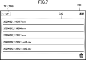
- FIG. 7 is an exemplary schematic diagram showing an example of a history image according to the embodiment;
- FIG. 1 is an exemplary schematic diagram showing an overview of an electroencephalogram recording device and an electroencephalograph according to an embodiment.
- FIG. 2 is an exemplary schematic block diagram showing functions of the electroencephalogram recording apparatus according to the embodiment.
- FIG. 3 is
- FIG. 8 is an exemplary schematic diagram showing an example of a confirmation image according to the embodiment
- FIG. 9 is an exemplary schematic diagram showing an example of a data recording format according to the embodiment
- FIG. 10 is an exemplary schematic diagram showing an example of a task recording format according to the embodiment.
- FIG. 11 is an exemplary schematic flow chart showing processing that is executed when the top image is displayed in the embodiment.
- FIG. 12 is an exemplary schematic flow chart showing processing that is executed when a preparation image is displayed in the embodiment.
- FIG. 13 is an exemplary schematic flow chart showing processing that is executed when a recorded image is displayed in the embodiment.
- FIG. 14 is an exemplary schematic flow chart showing processing that is executed when a history image is displayed in the embodiment.
- FIG. 15 is an exemplary and schematic flow chart showing processing that is executed when a confirmation image is displayed in the embodiment.
- FIG. 16 is an exemplary schematic block diagram showing an example of the hardware configuration of a computer that implements the electroencephalogram recording apparatus according to the embodiment;
- ordinal numbers such as “first,” “second,” etc. are used where appropriate, but these ordinal numbers are used for convenience of identification and are not intended for specific priorities. does not indicate
- FIG. 1 is an exemplary schematic diagram showing an overview of an electroencephalogram recording device 100 and an electroencephalograph 200 according to an embodiment.
- the electroencephalogram recording device 100 is an example of the “biological information recording device” of the present disclosure
- the electroencephalograph 200 is an example of the “biological information sensor” of the present disclosure.
- the electroencephalogram recording device 100 and electroencephalograph 200 are configured to perform wireless communication with each other.
- the electroencephalogram recording device 100 is configured as a mobile terminal having a display screen 101, such as a smart phone.
- the electroencephalograph 200 is configured as a wearable terminal that is worn on the subject X's head, for example.
- electroencephalography device 100 monitors subject X performing one or more tasks, such as tests or tasks that can be mentally or physically demanding, such as to check cognitive function. It is used to record electroencephalograms as biological information.
- the electroencephalogram recording apparatus 100 has functions as shown in FIG. 2 below.
- FIG. 2 is an exemplary and schematic block diagram showing functions of the electroencephalogram recording device 100 according to the embodiment.
- the electroencephalogram recording apparatus 100 includes an input reception unit 110, an acquisition processing unit 120, a recording processing unit 130, and a display processing unit 140.
- the input reception unit 110 receives an operation input for the electroencephalogram recording device 100 .
- Input of operation is performed, for example, by a user using the electroencephalogram recording device 100 (for example, an observer observing the subject X) via a touch panel (not shown) provided on the display screen 101 .
- the acquisition processing unit 120 acquires the electroencephalogram of the subject X detected by the electroencephalograph 200 . Then, the recording processing unit 130 records the electroencephalograms acquired by the acquisition processing unit 120 .
- the display processing unit 140 is configured to be able to display images as shown in FIGS. 3 to 8 below on the display screen 101.
- FIG. 1 the display processing unit 140 is configured to be able to display images as shown in FIGS. 3 to 8 below on the display screen 101.
- the display processing unit 140 displays a top image 300 as shown in FIG.
- FIG. 3 is an exemplary and schematic diagram showing an example of the top image 300 according to the embodiment. As shown in FIG. 3, top image 300 includes at least five regions 310, 320, 330, 340, and 350. In FIG. 3,
- An area 310 displays a user interface (button) 311 for receiving an operation input for disconnecting the electroencephalogram recording device 100 and the electroencephalograph 200 .
- An area 320 displays a user interface (button) 321 for accepting input of an operation for switching the currently displayed top image 300 to a later-described preparation image 400 (see FIG. 4).
- An area 330 displays a user interface (button) 331 for accepting input of an operation for switching the currently displayed top image 300 to a later-described history image 700 (see FIG. 7).
- a user interface is displayed that accepts input of an operation for setting an event that can occur in subject X who is performing a predetermined task.
- An event is a specific event that occurs in subject X while performing a task and that may introduce noise into the recorded brain waves.
- five events are set: blinking, body movement, yawning, conversation, and laughter.
- the user of the electroencephalogram recording apparatus 100 can additionally set new events other than blinking, body movement, yawning, conversation, and laughter by inputting a predetermined operation through the area 340, or can set a new event other than blinking, body movement, and laughter. At least one of motion, yawning, talking, and laughing can be changed to another event.
- a user interface is displayed that accepts an operation input for setting a task to be performed by subject X when recording an electroencephalogram.
- at least five events are set: eyes closed/rest, eyes open/rest, HAM-D, MADRS, and N-back task.
- the user of the electroencephalogram recording apparatus 100 inputs a predetermined operation via the area 350 to additionally perform a new task different from the eyes closed/rest, eyes open/rest, HAM-D, MADRS, and N-back tasks. or change at least one of the eyes closed/rest, eyes open/rest, HAM-D, MADRS, and N-back tasks to other tasks.
- the display processing unit 140 switches the display screen from the top image 300 to a preparation image 400 as shown in FIG. Displayed at 101.
- FIG. 4 is an exemplary and schematic diagram showing an example of the preparation image 400 according to the embodiment.
- the preliminary image 400 includes at least six regions 410, 420, 430, 440, 450, and 460.
- FIG. 4 is an exemplary and schematic diagram showing an example of the preparation image 400 according to the embodiment.
- the preliminary image 400 includes at least six regions 410, 420, 430, 440, 450, and 460.
- FIG. 4 is an exemplary and schematic diagram showing an example of the preparation image 400 according to the embodiment.
- the preliminary image 400 includes at least six regions 410, 420, 430, 440, 450, and 460.
- a user interface (button) 411 is displayed for receiving input of an operation to return the currently displayed preparation image 400 to the top image 300 (see FIG. 3).
- a user interface for receiving an operation input for inputting a designation operation for designating a task to be performed by the subject X during electroencephalogram recording is displayed.
- the user of the electroencephalogram recording apparatus 100 performs a designation operation by selecting the user interface of the area 420 to perform the task set in the area 350 (see FIG. 3) of the top image 300 and the subject to perform no task. It is possible to select one task from , and no tasks from .
- the user of the electroencephalogram recording apparatus 100 selects one task through the area 420 and instructs the subject X to perform the one task.
- Area 430 displays a user interface for accepting input of an operation for setting measurement options related to electroencephalogram recording
- area 440 displays a user interface for accepting input for operation of selecting preset measurement options.
- the user of electroencephalogram recording apparatus 100 can set the notch filter on/off, time constant, frequency of HPF, and frequency of LPF used when recording electroencephalograms by inputting predetermined operations via areas 430 and 440. is possible.
- a user interface (button) 451 is displayed for accepting input of an operation for selecting the dominant hand of the user of electroencephalogram recording device 100.
- the area 450 is an example of the "fifth area” of the present disclosure
- the user interface 451 is an example of the "third user interface” of the present disclosure.
- the user of the electroencephalogram recording apparatus 100 inputs a predetermined operation via the user interface 451 of the area 450 to record an image 500 for a right-handed person (see FIG. 5) when recording electroencephalograms, tasks, and events (see FIG. 5). is displayed on the display screen 101 or a recorded image 600 for a left-handed person (see FIG. 6), which will be described later, is displayed on the display screen 101.
- an area 460 there is an area for switching the currently displayed preparation image 400 to a recording image 500 (see FIG. 5) or a recording image 600 (see FIG. 6) for recording brain waves, tasks, and events, which will be described later.
- user interface (button) 461 is displayed.
- the display processing unit 140 selects that the user's right hand is the dominant hand via the user interface 451 of the area 450 and then inputs an operation to the user interface 461 of the area 460 as follows.
- a recording image 500 as shown in FIG. 5 is displayed on the display screen 101 by switching from the preparation image 400 .
- the recording processing unit 130 starts recording the electroencephalogram.
- FIG. 5 is an exemplary and schematic diagram showing an example of a right-handed recorded image 500 according to the embodiment.
- recorded image 500 includes at least five regions 510, 520, 530, 540, and 550.
- FIG. 5 is an exemplary and schematic diagram showing an example of a right-handed recorded image 500 according to the embodiment.
- recorded image 500 includes at least five regions 510, 520, 530, 540, and 550.
- FIG. 5 is an exemplary and schematic diagram showing an example of a right-handed recorded image 500 according to the embodiment.
- recorded image 500 includes at least five regions 510, 520, 530, 540, and 550.
- Region 510 changes in subject X's electroencephalogram over time are displayed in the form of a graph.
- Region 510 is an example of the “first region” of the present disclosure.
- two types of temporal changes are displayed in the area 510 , the temporal changes in the brain waves of the right brain and the temporal changes of the brain waves in the left brain.
- an electroencephalograph 200 that includes two electrodes, one for detecting brain waves in the right brain and one for detecting brain waves in the left brain. are doing.
- the recording processing unit 130 records the electroencephalogram indicating the temporal change displayed in the area 510 while the recorded image 500 is displayed on the display screen 101 .
- the name of the current task is displayed.
- Region 520 is an example of the “second region” of the present disclosure.
- the name of the task displayed in the area 520 is designated by a designation operation via the area 420 of the preparation image 400, and corresponds to the name of the task instructed by the user of the electroencephalogram recording apparatus 100 to the subject X to perform.
- the name of the task displayed in the area 520 is displayed on the graph showing the temporal change of the electroencephalogram displayed in the area 510 in such a manner that the timing at which the task started can be identified.
- the recording processing unit 130 records the task displayed in the area 520 in association with the electroencephalogram.
- a user interface (button) 531 is displayed for accepting input of a judgment operation for judging an event occurring in the subject X who is performing the task.
- the area 530 is an example of the "third area” of the present disclosure
- the user interface 531 is an example of the "first user interface” of the present disclosure.
- five events similar to the example shown in FIG. 1 are displayed in area 530 .
- the user of the electroencephalogram recording apparatus 100 can observe the subject X who is performing the task, and select the user interface 531 corresponding to the event every time the subject X experiences an event.
- the recording processing unit 130 records the event corresponding to the selected user interface 531 in association with the electroencephalogram and the task.
- the name of the event determined by the determination operation is displayed on the graph showing the temporal change of the electroencephalogram displayed in the area 510 in such a manner that the timing at which the event occurred can be identified.
- a user interface (button) 541 for accepting input of a change operation (task change operation) for changing the task so that the task to be performed by the subject X is specified again is displayed.
- the area 540 is an example of the "fourth area” of the present disclosure
- the user interface 541 is an example of the "second user interface” of the present disclosure.
- a user interface (button) 551 for accepting input of a termination operation is displayed.
- the recording processing unit 130 ends recording of the electroencephalogram, task, and event.
- the display processing unit 140 selects that the user's dominant hand is the left hand via the user interface 451 in the area 450 in the preparation image 400 (see FIG. 4), and then displays the user interface 461 in the area 460.
- a recorded image 600 as shown in FIG. 6 is displayed on the display screen 101 by switching from the preparation image 400 instead of the recorded image 500 described above.
- FIG. 6 is an exemplary schematic diagram showing an example of a left-handed recorded image 600 according to the embodiment.
- a recorded image 600 is basically the same as the recorded image 500 described above (see FIG. 5), except for the arrangement of some areas.
- the recorded image 600 includes at least five areas 610, 620, 630, 640, and 650 similar to the five areas 510, 520, 530, 540, and 550 described above (see FIG. 5), respectively.
- User interfaces (buttons) 631, 641, 659 displayed in areas 630, 640, and 650, respectively, are also similar to user interfaces 531, 541, and 551 (see FIG. 5) displayed in areas 530, 540, and 550, respectively. It is the same.
- a region 630 displaying a user interface 631 for accepting input of a judgment operation and a region 650 displaying a user interface 651 for accepting input of a termination operation display changes in electroencephalograms over time. is positioned to the left of the region 610 where the This is the opposite of the horizontal positional relationship of areas 510, 530, and 650 in recorded image 500 described above (see FIG. 5). According to the positional relationship as shown in FIG. 6, it is easy for a user whose left hand is dominant to perform determination operation and end operation, and according to the positional relationship shown in FIG. It becomes easy to perform determination operation and end operation.
- the display processing unit 140 displays a history image 700 as shown in FIG. , and displayed on the display screen 101 .
- FIG. 7 is an exemplary and schematic diagram showing an example of a history image 700 according to the embodiment. As shown in FIG. 7, historical image 700 includes at least two regions 710 and 720 .
- An area 710 displays a user interface (button) 711 that accepts an operation input to return the currently displayed history image 700 to the top image 300 (see FIG. 3).
- area 720 a list of recorded data is displayed.
- a user of the electroencephalogram recording apparatus 100 can input a predetermined operation via the area 720 to select one data item from the data listed in the area 720 .
- the display processing unit 140 switches from the history image 700 to display a confirmation image 800 shown in FIG. 8 on the display screen 101 so that the user can confirm the contents of the selected data.
- FIG. 8 is an exemplary and schematic diagram showing an example of a confirmation image 800 according to the embodiment.
- verification image 800 includes at least four regions 810, 820, 830, and 840.
- regions 810, 820, 830, and 840 are regions 810, 820, 830, and 840.
- An area 810 displays a user interface (button) 811 for accepting input of an operation to return the currently displayed confirmation image 800 to the history image 700 (see FIG. 7). Also, in area 820, at least part of the content of the data selected in history image 700 (for example, correspondence between brain waves, tasks, and events) is displayed in the form of a graph. In the example shown in FIG. 8, (at least a portion of) the recorded electroencephalogram is displayed in graphical form, and the recorded tasks and events can be identified when the task started and when the event occurred. displayed on the graph in the form of
- user interfaces 831 and 841 are displayed in areas 830 and 840, respectively, for accepting input of operations for changing the data displayed in area 810.
- FIG. 8 the user of electroencephalogram recording apparatus 100 can select how many seconds of data to display in area 810 by inputting a predetermined operation via user interface 841 of area 840 .
- By inputting a predetermined operation via the user interface 831 of the 830 it is possible to display data that is currently not within the range of the area 810 within the range of the area 810 .
- the recording processing unit 130 records various data in a format as shown in FIG. 9 below, for example.
- FIG. 9 is an exemplary and schematic diagram showing an example of a data recording format according to the embodiment.
- the recording processing unit 130 records various data in a format such as a table 900.
- the brain wave value of the left brain (Ch1-Left)
- the brain wave value of the right brain (Ch2-Right)
- the task identification number (Task Number)
- the event name (Event)
- a table 900 is associated with a total of 6 items of data, ie, the presence or absence of noise (Noise) and the timing (Time Stamp) at which these 5 items of data were acquired.
- table 900 shown in FIG. 9 does not record task names directly, but records task identification numbers. Therefore, in the embodiment, the correspondence between task identification numbers and task names is recorded in the format shown in FIG. 10 below.
- FIG. 10 is an exemplary and schematic diagram showing an example of a task recording format according to the embodiment.
- a task identification number (Task Number) and a task name (Task Name) are associated as a table 1000.
- the display processing unit 140 displays the aforementioned confirmation image 800 (see FIG. 8) on the display screen 101 based on this table 1000 and the aforementioned table 900 (see FIG. 9).
- the electroencephalogram recording apparatus 100 displays various images on the display screen 101 and accepts an operation input from a user (an observer who observes the subject X) to generate electroencephalograms, tasks, and events. , and allows the user to confirm the recorded data.
- FIG. 11 is an exemplary and schematic diagram showing processing that is executed when the top image 300 (see FIG. 3) is displayed in the embodiment.
- step S1101 the input receiving unit 110 determines whether or not a disconnection operation has been input.
- a disconnection operation is an operation for disconnecting the electroencephalogram recording device 100 and the electroencephalograph 200, which is input via the user interface 311 in the area 310 in the top image 300 (see FIG. 3).
- step S1101 If it is determined in step S1101 that a disconnection operation has been input, the process ends. On the other hand, if it is determined in step S1101 that the disconnection operation has not been input, the process proceeds to step S1102.
- step S1102 the input reception unit 110 determines whether or not an operation to shift to the preparation image 400 (see FIG. 4) has been input.
- the transition operation to the preparation image 400 is an operation input through the user interface 321 in the area 320 of the top image 300 (see FIG. 3).
- step S1102 If it is determined in step S1102 that an operation to move to the preparation image 400 (see FIG. 4) has been input, the process proceeds to step S1103. Then, in step S1103, the display processing unit 140 switches the image displayed on the display screen 101 from the currently displayed top image 300 (see FIG. 3) to the preparation image 400. FIG. Then, when the switching to the preparation image 400 is completed, the process shown in FIG. 11 ends, and the process shifts to the process shown in FIG. 12 (details will be described later).
- step S1102 determines whether or not an operation to shift to history image 700 (see FIG. 7) has been input.
- the operation to move to the history image 700 is an operation input via the user interface 331 in the area 330 in the top image 300 (see FIG. 3).
- step S1104 If it is determined in step S1104 that an operation to move to the history image 700 (see FIG. 7) has been input, the process proceeds to step S1105. Then, in step S1105, the display processing unit 140 switches the image displayed on the display screen 101 from the currently displayed top image 300 (see FIG. 3) to the history image 700. FIG. Then, when the switching to the history image 700 is completed, the process shown in FIG. 11 ends, and the process shifts to the process shown in FIG. 14 (details will be described later).
- step S1104 determines whether or not another setting change operation has been input.
- Other setting change operations are operations input via areas 340 and 350 in top image 300 (see FIG. 3).
- step S1106 If it is determined in step S1106 that no setting change operation has been input, the process returns to step S1101. On the other hand, if it is determined in step S1106 that a setting change operation has been input, the process proceeds to step S1107. Then, in step S1107, the display processing unit 140 changes the setting according to the input setting change operation, and changes the display content of the top image 300 (see FIG. 3) as necessary. Then, the process returns to step S1101.
- FIG. 12 is an exemplary and schematic diagram showing processing executed when the preparation image 400 (see FIG. 4) is displayed in the embodiment.
- step S1201 the input receiving unit 110 determines whether or not a return operation has been input.
- a return operation is an operation input via the user interface 411 in the area 410 in the preparation image 400 (see FIG. 4).
- step S1201 If it is determined in step S1201 that a return operation has been input, the process proceeds to step S1202. Then, in step S1202, the display processing unit 140 switches the image displayed on the display screen 101 from the currently displayed preparation image 400 (see FIG. 4) to the top image 300 (see FIG. 3). Then, when the switching to the top image 300 is completed, the processing shown in FIG. 12 ends, and the processing shifts to the processing shown in FIG.
- step S1201 determines whether or not a recording start operation has been input.
- a recording start operation is an operation input via the user interface 461 in the area 460 in the preparation image 400 (see FIG. 4).
- step S1203 If it is determined in step S1203 that a recording start operation has been input, the process proceeds to step S1204. Then, in step S1204, display processing unit 140 selects an image to be displayed on display screen 101 from currently displayed preparation image 400 (see FIG. 4) to recorded image 500 (see FIG. 5) or recorded image 600 (see FIG. 6). ). Then, when the switching to the recorded image 500 or 600 is completed, the process shown in FIG. 12 ends, and the process shifts to the process shown in FIG. 13 (details will be described later).
- step S1203 determines whether or not the recording start operation has been input.
- step S1205 input reception unit 110 determines whether or not a designation operation has been input.
- a designation operation is an operation input via an area 420 in the preparation image 400 (see FIG. 4).
- step S1205 If it is determined in step S1205 that a specifying operation has been input, the process proceeds to step S1206. Then, in step S1206, the display processing unit 140 sets a task to be recorded in association with the electroencephalogram measurement value whose recording is to be started in response to a future recording start operation, and if necessary, prepares the preparation image 400 (Fig. 4) to change the display contents. Then, the process returns to step S1201.
- step S1205 determines whether or not another setting change operation (including a switching operation) has been input.
- Other setting change operations are operations input via areas 430, 440, and 450 in preparation image 400 (see FIG. 4).
- operations input through the user interface 451 in the area 450 are displayed on the display screen 101 during recording of brain waves, tasks, and events by displaying a recorded image 500 for right-handers (see FIG. 5) or is expressed as a switching operation in the sense that it is an operation for switching whether to display the recorded image 600 (see FIG. 6).
- step S1207 If it is determined in step S1207 that no setting change operation has been input, the process returns to step S1201. On the other hand, if it is determined in step S1207 that a setting change operation has been input, the process advances to step S1208. Then, in step S1208, the display processing unit 140 changes the setting according to the input setting change operation, and changes the display contents of the preparation image 400 (see FIG. 4) as necessary. Then, the process returns to step S1201.
- FIG. 13 is an exemplary and schematic diagram showing processing that is executed when the recorded image 500 (see FIG. 5) or the recorded image 600 (see FIG. 6) is displayed in the embodiment. As described above, which of the recorded images 500 and 600 is displayed is switched according to the switching operation input in step S1207 of FIG. 12, for example.
- step S1301 the recording processing unit 130 selects the measurement value of the electroencephalogram acquired by the acquisition processing unit 120 and the specified operation input in step S1205 of FIG.
- the task is associated with and recorded.
- the display processing unit 140 displays the data being recorded within the area 510 of the recorded image 500 (see FIG. 5) or within the area 610 of the recorded image 600 (see FIG. 6).
- step S1302 the input receiving unit 110 determines whether or not an end operation has been input.
- the end operation is an operation input through the user interface 551 in the area 550 in the recorded image 500 (see FIG. 5) or the user interface 651 in the area 650 in the recorded image 600 (see FIG. 6).
- step S1302 If it is determined in step S1302 that an end operation has been input, the process proceeds to step S1303. Then, in step S1303, recording processing unit 130 saves the data recording result up to the present time in a format such as table 900 (see FIG. 9) described above, for example. Then the process ends.
- step S1302 determines whether or not a determination operation has been input.
- the determination operation is an operation input through the user interface 531 in the area 530 in the recorded image 500 (see FIG. 5) or the user interface 631 in the area 630 in the recorded image 600 (see FIG. 6).
- step S1304 If it is determined in step S1304 that a determination operation has been input, the process proceeds to step S1305. Then, in step S1305, the recording processing unit 130 records the event determined by the determination operation in association with the electroencephalogram measurement value and the task being recorded. At this time, the display processing unit 140 displays the recorded event within the area 510 of the recorded image 500 (see FIG. 5) or within the area 610 of the recorded image 600 (see FIG. 6). Then, the process returns to step S1301.
- step S1305 determines whether or not a task change operation has been input.
- a task change operation is an operation input through the user interface 541 in the area 540 in the recorded image 500 (see FIG. 5) or the user interface 641 in the area 640 in the recorded image 600 (see FIG. 6).
- step S1306 If it is determined in step S1306 that a task change operation has not been input, the process returns to step S1301. On the other hand, if it is determined in step S1306 that a task change operation has been input, the process advances to step S1307. Then, in step S1307, the recording processing unit 130 changes the recorded task, and the display processing unit 140 displays the task in the area 520 of the recorded image 500 (see FIG. 5) or in the recorded image 600 (see FIG. 6). Change the display content in area 620 . At this time, the display processing unit 140 also changes the task displayed within the area 510 of the recorded image 500 or within the area 610 of the recorded image 600 . Then, the process returns to step S1301.
- FIG. 14 is an exemplary and schematic diagram showing processing executed when the history image 700 (see FIG. 7) is displayed in the embodiment.
- step S1401 the input receiving unit 110 determines whether or not a return operation has been input.
- a return operation is an operation input via the user interface 711 in the area 710 in the history image 700 (see FIG. 7).
- step S1401 If it is determined in step S1401 that a return operation has been input, the process proceeds to step S1402. Then, in step S1402, the display processing unit 140 switches the image displayed on the display screen 101 from the currently displayed history image 700 (see FIG. 7) to the top image 300 (see FIG. 3). When the switching to the top image 300 is completed, the processing shown in FIG. 14 ends, and the processing shifts to the processing shown in FIG.
- step S1401 determines whether or not a selection operation has been input.
- a selection operation is an operation input via an area 720 in the history image 700 (see FIG. 7).
- step S1403 If it is determined in step S1403 that no selection operation has been input, the process returns to step S1401. On the other hand, if it is determined in step S1403 that a selection operation has been input, the process advances to step S1404. Then, in step S1404, the display processing unit 140 switches the image displayed on the display screen 101 from the currently displayed history image 700 (see FIG. 7) to the confirmation image 800 (see FIG. 8). Then, when the switching to the confirmation image 800 is completed, the processing shown in FIG. 14 ends, and the processing shifts to the next processing shown in FIG.
- FIG. 15 is an exemplary and schematic diagram showing the processing executed when the confirmation image 800 (see FIG. 8) is displayed in the embodiment.
- step S1501 the input receiving unit 110 determines whether or not a return operation has been input.
- a return operation is an operation input through the user interface 811 in the area 810 in the confirmation image 800 (see FIG. 8).
- step S1501 If it is determined in step S1501 that a return operation has been input, the process proceeds to step S1502. Then, in step S1502, the display processing unit 140 switches the image displayed on the display screen 101 from the currently displayed confirmation image 800 (see FIG. 8) to the history image 700 (see FIG. 7). Then, when the switching to the history image 700 is completed, the processing shown in FIG. 15 ends, and the processing shifts to the processing shown in FIG.
- step S1501 determines whether or not an operation to change other display contents has been input.
- Other display content change operations are operations input via the user interface 831 in the area 830 and the user interface 841 in the area 840 in the confirmation image 800 (see FIG. 8).
- step S1503 If it is determined in step S1503 that an operation to change the display content has not been input, the process returns to step S1501. On the other hand, if it is determined in step S1503 that an operation to change the display content has been input, the process advances to step S1504. Then, in step S1504, display processing unit 140 changes the display content in area 820 of confirmation image 800 (see FIG. 8) in accordance with the input display content change operation. Then the process ends.
- the electroencephalogram recording apparatus 100 includes the acquisition processing unit 120 and the recording processing unit 130.
- the acquisition processing unit 120 acquires the electroencephalogram of the subject X detected by the electroencephalograph 200 .
- the recording processing unit 130 records the electroencephalogram acquired by the acquisition processing unit 120, and when the observer observing the subject X performs a designation operation for designating a task to be performed by the subject X during recording of the electroencephalogram , the task is further recorded in association with the EEG.
- the recording processing unit 130 associates the event with the electroencephalogram and the task. Record more.
- the electroencephalogram recording device 100 includes a display processing unit 140 in the embodiment.
- the display processing unit 140 A region 510 (or 610) in which changes over time in the electroencephalogram are displayed, a region 520 (or 620) in which the name of the task is displayed, and a user interface 531 (or 631) is displayed on the display screen 101.
- the recorded image 500 includes an area 540 (or 640) in which a user interface 541 (or 641) for accepting input of a change operation for changing the task to perform the specified operation again is displayed. Including further.
- the display processing unit 140 changes the area 530 (or 630) to the area 510 (or 620) in the recorded image 500 (or 600). ) is displayed on the display screen 101, the preparation image 400 including an area 450 in which a user interface 451 for receiving an input of a switching operation for switching between arranging on the left side and arranging on the right side is displayed.
- the switching operation using the preparation image 400 makes it easy to select the recorded image 500 that is easy for a right-handed user to perform the determination operation and the recorded image 600 that is easy for a left-handed user to perform the determination operation. can do.
- the electroencephalogram recording apparatus 100 is implemented by a computer 1600 having a hardware configuration as shown in FIG. 16 below, for example.
- FIG. 4 is an exemplary and schematic block diagram showing the hardware configuration of a computer 1600 that implements the electroencephalogram recording apparatus 100 according to the embodiment.
- FIG. 4 is an exemplary and schematic block diagram showing the hardware configuration of a computer 1600 that implements the electroencephalogram recording apparatus 100 according to the embodiment.
- FIG. 4 is an exemplary and schematic block diagram showing the hardware configuration of a computer 1600 that implements the electroencephalogram recording apparatus 100 according to the embodiment.
- the computer 1600 includes a processor 1610, a memory 1620, a storage 1630, an input/output interface (I/F) 1640, and a communication interface (I/F) 1650. These hardware are connected to bus 1660 .
- the processor 1610 is configured, for example, as a CPU (Central Processing Unit) and controls the operation of each part of the computer 1600 in an integrated manner.
- CPU Central Processing Unit
- Memory 1620 includes, for example, ROM (Read Only Memory) and RAM (Random Access Memory), volatile or non-volatile storage of various data such as programs executed by processor 1610, and processor 1610 executes programs.
- ROM Read Only Memory
- RAM Random Access Memory
- the storage 1630 includes, for example, an HDD (Hard Disk Drive) or an SSD (Solid State Drive), and stores various data in a non-volatile manner.
- HDD Hard Disk Drive
- SSD Solid State Drive
- the input/output interface 1640 inputs data from input devices (not shown) such as a keyboard and mouse to the computer 1600 and outputs data from the computer 1600 to output devices (not shown) such as a display and speakers. to control the output of input devices (not shown) such as a keyboard and mouse to the computer 1600 and outputs data from the computer 1600 to output devices (not shown) such as a display and speakers. to control the output of input devices (not shown) such as a keyboard and mouse to the computer 1600 and outputs data from the computer 1600 to output devices (not shown) such as a display and speakers. to control the output of
- Communication interface 1650 allows computer 1600 to communicate with other devices, either wired or wirelessly.
- the functions of the electroencephalogram recording apparatus 100 are the functions of cooperation between hardware and software as a result of processor 1610 executing an electroencephalogram recording program pre-stored in memory 1620 or storage 1630. Implemented as a group of modules. However, in the embodiment, some or all of the functional modules shown in FIG. 2 may be realized only by hardware such as specially designed circuits.
- the electroencephalogram recording program described above does not necessarily have to be stored in advance in memory 1620 or storage 1630 .
- the electroencephalogram recording program described above can be installed in a computer-readable medium, such as various magnetic disks such as a flexible disk (FD), or various optical disks such as a DVD (Digital Versatile Disk). It may also be provided as a computer program product coded in an executable form.
- the electroencephalogram recording program described above may be provided or distributed via a network such as the Internet. That is, the recording program described above may be provided in a form of being stored on a computer connected to a network such as the Internet, and being downloaded via the network.
- the electroencephalogram recording device 100 configured as a mobile terminal such as a smartphone is exemplified as an example of the biological information recording device.
- the electroencephalogram recording device 100 may be configured as a non-portable terminal.
- an observer who observes a subject performs a designation operation for designating a task to be performed by the subject during recording of biometric information.
- the mechanical device comprises, for example, a camera that takes an overview of the subject and a computer that includes at least one processor.
- This processor for example, performs a designation operation by arbitrarily designating a task to be performed by the subject, displays the designated task on the input/output interface (I / F) of the computer, and records the task information. forwarded to and recorded. This allows accurate recording of task information.
- the observer performs a determination operation to determine an event that occurs in the subject during the recording of the biological information and the task.
- a mechanical device comprises, for example, a camera that takes an overview of the subject and a computer that includes at least one processor.
- This processor for example, performs a determination operation by determining an event that occurs in the subject based on the image from the camera, transfers the determination operation to the recording processing unit, and records the determination operation.
- the event determination operation can be accurately recorded.
- biological information recording device 101 display screen 120 acquisition processing unit 130 recording processing unit 140 display processing unit 200 electroencephalograph 400 preparation image 450 region (fifth region) 451 user interface (second user interface) 500, 600 recorded image 510, 610 area (first area) 520, 620 area (second area) 530, 630 area (third area) 531, 631 user interface (first user interface) 540, 640 area (fourth area) 541, 641 User interface (second user interface)
Landscapes
- Health & Medical Sciences (AREA)
- Life Sciences & Earth Sciences (AREA)
- Biomedical Technology (AREA)
- Molecular Biology (AREA)
- Psychology (AREA)
- Biophysics (AREA)
- Pathology (AREA)
- Engineering & Computer Science (AREA)
- Psychiatry (AREA)
- Heart & Thoracic Surgery (AREA)
- Medical Informatics (AREA)
- Physics & Mathematics (AREA)
- Surgery (AREA)
- Animal Behavior & Ethology (AREA)
- General Health & Medical Sciences (AREA)
- Public Health (AREA)
- Veterinary Medicine (AREA)
- Measurement And Recording Of Electrical Phenomena And Electrical Characteristics Of The Living Body (AREA)
- Measuring And Recording Apparatus For Diagnosis (AREA)
Priority Applications (6)
| Application Number | Priority Date | Filing Date | Title |
|---|---|---|---|
| EP22867350.5A EP4400053A1 (en) | 2021-09-07 | 2022-09-06 | Biological information recording device and biological information recording program |
| CA3231719A CA3231719A1 (en) | 2021-09-07 | 2022-09-06 | Biological information recording device and biological information recording program |
| US18/690,149 US20240374200A1 (en) | 2021-09-07 | 2022-09-06 | Biological information recording device and biological information recording program |
| CN202280060597.1A CN117979903A (zh) | 2021-09-07 | 2022-09-06 | 生物体信息记录装置和生物体信息记录程序 |
| JP2023539045A JP7447363B2 (ja) | 2021-09-07 | 2022-09-06 | 生体情報記録装置、および生体情報記録プログラム |
| JP2024028777A JP2024063102A (ja) | 2021-09-07 | 2024-02-28 | 生体情報記録装置、および生体情報記録プログラム |
Applications Claiming Priority (2)
| Application Number | Priority Date | Filing Date | Title |
|---|---|---|---|
| JP2021-145252 | 2021-09-07 | ||
| JP2021145252 | 2021-09-07 |
Publications (1)
| Publication Number | Publication Date |
|---|---|
| WO2023038028A1 true WO2023038028A1 (ja) | 2023-03-16 |
Family
ID=85507607
Family Applications (1)
| Application Number | Title | Priority Date | Filing Date |
|---|---|---|---|
| PCT/JP2022/033450 Ceased WO2023038028A1 (ja) | 2021-09-07 | 2022-09-06 | 生体情報記録装置、および生体情報記録プログラム |
Country Status (6)
| Country | Link |
|---|---|
| US (1) | US20240374200A1 (https=) |
| EP (1) | EP4400053A1 (https=) |
| JP (2) | JP7447363B2 (https=) |
| CN (1) | CN117979903A (https=) |
| CA (1) | CA3231719A1 (https=) |
| WO (1) | WO2023038028A1 (https=) |
Citations (4)
| Publication number | Priority date | Publication date | Assignee | Title |
|---|---|---|---|---|
| JP2014233458A (ja) * | 2013-06-03 | 2014-12-15 | 株式会社島津製作所 | 脳機能計測用動画生成装置および脳機能計測用動画生成システム |
| JP2017060571A (ja) * | 2015-09-24 | 2017-03-30 | 株式会社日立製作所 | 診断補助システム、及び診断補助情報表示方法 |
| US9867571B2 (en) | 2014-01-06 | 2018-01-16 | Interaxon Inc. | Wearable apparatus for brain sensors |
| JP2018525042A (ja) * | 2015-07-06 | 2018-09-06 | アボット ダイアベティス ケア インコーポレイテッドAbbott Diabetes Care Inc. | エピソードの検出及び評価のためのシステム、装置、及び方法 |
Family Cites Families (5)
| Publication number | Priority date | Publication date | Assignee | Title |
|---|---|---|---|---|
| DE3246025T1 (de) * | 1981-05-15 | 1984-10-04 | The Children's Hospital Medical Center, Boston, Mass. | Mapping der elektrischen Gehirnaktivität |
| EP2260760B1 (en) | 2004-06-18 | 2014-08-27 | Neuronetrix Solutions, LLC | Evoked response testing method for neurological disorders |
| JP2014012040A (ja) | 2012-07-03 | 2014-01-23 | Sony Corp | 入力装置および情報処理システム |
| KR20150003560A (ko) | 2013-07-01 | 2015-01-09 | 삼성전자주식회사 | 사용자의 모션 정보에 기초하여 사용자 인터페이스(ui)를 변경시키는 방법 및 장치 |
| EP3698710B1 (en) | 2017-10-20 | 2025-07-09 | LIFESCAPES Inc. | Brain wave measurement system, brain wave measurement method, program, and non-transitory recording medium |
-
2022
- 2022-09-06 JP JP2023539045A patent/JP7447363B2/ja active Active
- 2022-09-06 WO PCT/JP2022/033450 patent/WO2023038028A1/ja not_active Ceased
- 2022-09-06 CA CA3231719A patent/CA3231719A1/en active Pending
- 2022-09-06 EP EP22867350.5A patent/EP4400053A1/en not_active Withdrawn
- 2022-09-06 CN CN202280060597.1A patent/CN117979903A/zh not_active Withdrawn
- 2022-09-06 US US18/690,149 patent/US20240374200A1/en active Pending
-
2024
- 2024-02-28 JP JP2024028777A patent/JP2024063102A/ja active Pending
Patent Citations (4)
| Publication number | Priority date | Publication date | Assignee | Title |
|---|---|---|---|---|
| JP2014233458A (ja) * | 2013-06-03 | 2014-12-15 | 株式会社島津製作所 | 脳機能計測用動画生成装置および脳機能計測用動画生成システム |
| US9867571B2 (en) | 2014-01-06 | 2018-01-16 | Interaxon Inc. | Wearable apparatus for brain sensors |
| JP2018525042A (ja) * | 2015-07-06 | 2018-09-06 | アボット ダイアベティス ケア インコーポレイテッドAbbott Diabetes Care Inc. | エピソードの検出及び評価のためのシステム、装置、及び方法 |
| JP2017060571A (ja) * | 2015-09-24 | 2017-03-30 | 株式会社日立製作所 | 診断補助システム、及び診断補助情報表示方法 |
Also Published As
| Publication number | Publication date |
|---|---|
| JP7447363B2 (ja) | 2024-03-11 |
| US20240374200A1 (en) | 2024-11-14 |
| JPWO2023038028A1 (https=) | 2023-03-16 |
| CN117979903A (zh) | 2024-05-03 |
| JP2024063102A (ja) | 2024-05-10 |
| CA3231719A1 (en) | 2023-03-16 |
| EP4400053A1 (en) | 2024-07-17 |
Similar Documents
| Publication | Publication Date | Title |
|---|---|---|
| JP5985116B1 (ja) | 意図を介した拡張現実における仮想オブジェクトの操作 | |
| KR101694089B1 (ko) | 사고를 통한 증강 현실에서의 가상 물체의 조작 | |
| US20150317810A1 (en) | User Interfaces for Mobile and Wearable Medical Devices | |
| JP2014021986A (ja) | コンテンツ提供方法及びそれを適用したディスプレイ装置 | |
| CN105793918B (zh) | 同时显示多个视频源的视频数据 | |
| JP6356963B2 (ja) | 機械装置 | |
| JP2016131741A (ja) | 通信端末、面談システム、表示方法及びプログラム | |
| JP2016163166A (ja) | 通信端末、面談システム、表示方法及びプログラム | |
| CN115268647A (zh) | 脑功能分析装置的交互操作方法及脑功能分析装置 | |
| JP2020151082A (ja) | 情報処理装置、情報処理方法、プログラムおよび生体信号計測システム | |
| JP2004282471A (ja) | 映像コンテンツの評価装置 | |
| JP7447363B2 (ja) | 生体情報記録装置、および生体情報記録プログラム | |
| HK40103633A (zh) | 生物体信息记录装置和生物体信息记录程序 | |
| JP6962188B2 (ja) | 情報処理装置、生体信号計測システム、及びプログラム | |
| JP2016163150A (ja) | 通信端末、面談システム、通信方法及びプログラム | |
| JP2017069827A (ja) | 通信端末、面談システム、表示方法及びプログラム | |
| KR102758193B1 (ko) | 커넥티드 워치의 착용자의 라이프에서의 특정 이벤트를 아카이브하기 위한 방법 | |
| KR20190022071A (ko) | 의료 영상 표시 시스템 | |
| JPWO2023038028A5 (https=) | ||
| JP2024063102A5 (https=) | ||
| JP2005250846A (ja) | 電子カルテ表示装置 | |
| JP2007503241A (ja) | 超音波イメージングシステムのためのリビューモードグラフィックユーザインタフェース | |
| KR20170064298A (ko) | 체온 정보 표시를 위한 단말 및 그 제어방법 | |
| JP2017016506A (ja) | 通信端末、面談システム、表示方法及びプログラム | |
| JP2004348245A (ja) | 操作パネル表示装置、および操作パネル表示プログラム |
Legal Events
| Date | Code | Title | Description |
|---|---|---|---|
| 121 | Ep: the epo has been informed by wipo that ep was designated in this application |
Ref document number: 22867350 Country of ref document: EP Kind code of ref document: A1 |
|
| WWE | Wipo information: entry into national phase |
Ref document number: 2023539045 Country of ref document: JP |
|
| WWE | Wipo information: entry into national phase |
Ref document number: 18690149 Country of ref document: US Ref document number: 202280060597.1 Country of ref document: CN Ref document number: 3231719 Country of ref document: CA |
|
| WWE | Wipo information: entry into national phase |
Ref document number: 2022867350 Country of ref document: EP |
|
| NENP | Non-entry into the national phase |
Ref country code: DE |
|
| ENP | Entry into the national phase |
Ref document number: 2022867350 Country of ref document: EP Effective date: 20240408 |
|
| WWW | Wipo information: withdrawn in national office |
Ref document number: 2022867350 Country of ref document: EP |