WO2023037808A1 - 止血弁の開閉機構、長尺状医療機器の固定機構および医療用コネクタ - Google Patents
止血弁の開閉機構、長尺状医療機器の固定機構および医療用コネクタ Download PDFInfo
- Publication number
- WO2023037808A1 WO2023037808A1 PCT/JP2022/030210 JP2022030210W WO2023037808A1 WO 2023037808 A1 WO2023037808 A1 WO 2023037808A1 JP 2022030210 W JP2022030210 W JP 2022030210W WO 2023037808 A1 WO2023037808 A1 WO 2023037808A1
- Authority
- WO
- WIPO (PCT)
- Prior art keywords
- force transmission
- opening
- housing
- pressing
- transmission member
- Prior art date
- Legal status (The legal status is an assumption and is not a legal conclusion. Google has not performed a legal analysis and makes no representation as to the accuracy of the status listed.)
- Ceased
Links
Images


Classifications
-
- A—HUMAN NECESSITIES
- A61—MEDICAL OR VETERINARY SCIENCE; HYGIENE
- A61M—DEVICES FOR INTRODUCING MEDIA INTO, OR ONTO, THE BODY; DEVICES FOR TRANSDUCING BODY MEDIA OR FOR TAKING MEDIA FROM THE BODY; DEVICES FOR PRODUCING OR ENDING SLEEP OR STUPOR
- A61M25/00—Catheters; Hollow probes
- A61M25/01—Introducing, guiding, advancing, emplacing or holding catheters
- A61M25/02—Holding devices, e.g. on the body
-
- A—HUMAN NECESSITIES
- A61—MEDICAL OR VETERINARY SCIENCE; HYGIENE
- A61M—DEVICES FOR INTRODUCING MEDIA INTO, OR ONTO, THE BODY; DEVICES FOR TRANSDUCING BODY MEDIA OR FOR TAKING MEDIA FROM THE BODY; DEVICES FOR PRODUCING OR ENDING SLEEP OR STUPOR
- A61M39/00—Tubes, tube connectors, tube couplings, valves, access sites or the like, specially adapted for medical use
- A61M39/02—Access sites
- A61M39/06—Haemostasis valves, i.e. gaskets sealing around a needle, catheter or the like, closing on removal thereof
- A61M2039/062—Haemostasis valves, i.e. gaskets sealing around a needle, catheter or the like, closing on removal thereof used with a catheter
-
- A—HUMAN NECESSITIES
- A61—MEDICAL OR VETERINARY SCIENCE; HYGIENE
- A61M—DEVICES FOR INTRODUCING MEDIA INTO, OR ONTO, THE BODY; DEVICES FOR TRANSDUCING BODY MEDIA OR FOR TAKING MEDIA FROM THE BODY; DEVICES FOR PRODUCING OR ENDING SLEEP OR STUPOR
- A61M39/00—Tubes, tube connectors, tube couplings, valves, access sites or the like, specially adapted for medical use
- A61M39/02—Access sites
- A61M39/06—Haemostasis valves, i.e. gaskets sealing around a needle, catheter or the like, closing on removal thereof
- A61M39/0613—Haemostasis valves, i.e. gaskets sealing around a needle, catheter or the like, closing on removal thereof with means for adjusting the seal opening or pressure
Definitions
- the technology disclosed in this specification relates to a hemostatic valve opening/closing mechanism, a fixing mechanism for a long medical device, and a medical connector.
- a Y connector is a medical connector that is used by being connected to a guiding catheter.
- the Y connector has a main tube and a branch tube branched from the main tube.
- An elongated medical device such as a guide wire or a catheter is introduced into the guiding catheter through the main tube and branched.
- Liquid agents such as a contrast medium and physiological saline are supplied through the tube.
- the Y connector is provided with an opening/closing mechanism for opening and closing a hemostatic valve that suppresses the outflow of blood through the lumen of the main tube, and a fixing mechanism for fixing the long medical device.
- a penetrating member (opener) having a through hole coaxial with the lumen of the main pipe is provided.
- an open state in which the hemostatic valve is opened by the penetrating member pressing the hemostatic valve, and a closed state in which the hemostatic valve is closed by the penetrating member being separated from the hemostatic valve.
- an elastic fixing valve having a through hole through which the long medical device is inserted is provided.
- the operation of opening and closing the hemostatic valve is an operation of pressing the penetrating member in the axial direction of the lumen of the main tube, so there is a problem that the operation is difficult.
- fixing/unfixing the elongated medical device is an operation of rotating the screw. There is a problem that it is not possible to grasp the tactile sense or visually.
- This specification discloses a technology capable of solving the above-described problems.
- a hemostatic valve opening/closing mechanism disclosed in the present specification includes a housing, a hemostatic valve, a penetrating member, an operation member, a force transmission member, and a holding mechanism.
- the housing is a tubular member having a lumen that communicates with the distal opening and the proximal opening.
- the hemostatic valve is mounted in the housing and is normally in a closed state, and when pressed from the proximal end side, it is in an open state in which a through hole communicating with the distal end side opening of the housing is formed.
- the penetrating member is housed in the housing slidably along the first direction, which is the extending direction of the lumen, on the proximal side of the hemostatic valve.
- a through hole is formed in the through member to communicate with the base end side opening of the housing.
- the penetrating member has a first position in which the hemostasis valve is closed, and a position on the distal side of the first position along the first direction, and presses the hemostasis valve to close the hemostasis valve. a second position in which the hemostasis valve is in the open state and the through hole of the hemostasis valve and the through hole of the penetrating member are communicated with each other;
- the operating member is a member that can slide along a second direction that is non-parallel to the first direction.
- a force transmission member is disposed between the penetrating member and the operating member so as to be slidable in the second direction, and the operating member moves along the second direction so as to approach the penetrating member.
- the force transmission member can be positioned in a third position that positions the penetrating member in the first position and in a fourth position that presses the penetrating member to position the penetrating member in the second position.
- the holding mechanism holds the force transmission member at the third position or holds the force transmission member at the fourth position each time the operation member slides in the second direction. It is a mechanism that switches to the held state.
- the holding mechanism holds the force transmission member at the third position or holds the force transmission member at the fourth position. , and then switch to .
- the holding mechanism switches to the state of holding the force transmission member at the fourth position as the operation member slides, the penetrating member moves from the first position to the second position, and the hemostasis valve changes from the closed state to the open state. switch to At this time, the holding mechanism holds the force transmission member at the fourth position, thereby maintaining the open state of the hemostatic valve.
- the holding mechanism switches to the state in which the force transmission member is held at the third position as the operating member slides again, the penetrating member moves from the second position to the first position, opening the hemostasis valve. state to the closed state. At this time, the holding mechanism holds the force transmission member at the third position, thereby maintaining the closed state of the hemostatic valve.
- the operating member is slidable along the second direction non-parallel to the extending direction of the lumen of the housing. This is an operation of pressing in a second direction that is non-parallel to the extending direction of the cavity.
- the operator can easily perform the opening/closing operation of the hemostatic valve with the thumb or forefinger while holding the device provided with the present opening/closing mechanism, thereby improving the operability of the opening/closing mechanism. can be done.
- the operation member and the force transmission member may be configured as an integral member. According to this hemostatic valve opening/closing mechanism, the number of parts can be reduced.
- the holding mechanism is a cylinder that urges the force transmission member in the second direction toward the outside of the housing, either directly or via another member. and a convex portion inserted into the hollow portion of the biasing member is formed on the surface of the force transmission member or the other member facing the biasing member. good too.
- the opening/closing mechanism of the hemostasis valve positioning between the force transmission member and the biasing member can be performed easily and accurately, and the biasing force of the biasing member can be effectively transmitted to the force transmission member. It is possible to improve the accuracy of the operation of the opening/closing mechanism.
- the angle between the first direction and the second direction may be 35 degrees or more and 55 degrees or less. According to the opening and closing mechanism of the hemostatic valve, the operator can easily open and close the hemostatic valve with the thumb while holding the device equipped with the opening and closing mechanism. can be improved.
- the penetrating member includes a body portion having the through hole formed therein, a flange portion projecting from the body portion in a third direction perpendicular to the first direction, wherein the force transmission member is configured to be slidable relative to the penetrating member along the third direction while abutting on the proximal surface of the flange portion may be According to this hemostasis valve opening/closing mechanism, the sliding of the force transmission member along the second direction non-parallel to the extending direction of the lumen of the housing and the sliding of the penetrating member in the extending direction can be efficiently performed. can be effectively converted, and the operability of the opening/closing mechanism can be effectively improved.
- the angle between the first direction and the second direction may be approximately 90 degrees. According to this hemostatic valve opening/closing mechanism, an operator can very easily open/close the hemostatic valve with a thumb or forefinger while holding the device equipped with this opening/closing mechanism. can be substantially improved.
- the force transmission member is slidable in the second direction, and the penetrating member is perpendicular to both the first direction and the second direction. and the force transmission member has a groove into which the protrusion is inserted, the groove being perpendicular to the fourth direction and the first direction.
- a configuration may be employed in which grooves extending in non-parallel directions are formed in both of the second directions. According to the opening and closing mechanism of the hemostasis valve, the sliding of the force transmission member along the second direction substantially orthogonal to the extending direction of the lumen of the housing and the sliding of the penetrating member in the extending direction can be efficiently performed. , and the operability of the opening/closing mechanism can be effectively improved.
- a fixing mechanism for a long medical device disclosed in this specification includes a housing, a tubular body, a pressing member, an operation member, a force transmission member, and a holding mechanism.
- the housing is a tubular member having a lumen that communicates with the distal opening and the proximal opening.
- a circular tubular body is a flexible member that is attached within the housing and has a through hole formed therein, into which the elongated medical device is inserted.
- the through-hole of the tubular body communicates with the distal side opening and the proximal side opening of the housing.
- the pressing member is housed in the housing slidably along a sixth direction orthogonal to a fifth direction parallel to the axis of the tubular body.
- the pressing member is at a fifth position and a sixth position displaced from the fifth position along the sixth direction, and presses a portion of the cylindrical body excluding both end portions from the outer peripheral side. and a sixth position that deforms the
- the operation member is a member slidable along a seventh direction non-parallel to the fifth direction.
- the force transmission member is disposed between the pressing member and the operation member so as to be slidable in the seventh direction, and moves along the seventh direction so that the operation member approaches the pressing member. It is a member that transmits force to the pressing member.
- the force transmission member can be positioned at a seventh position that positions the pressing member at the fifth position, and an eighth position that presses the pressing member to position the pressing member at the sixth position.
- the holding mechanism 260 holds the force transmission member at the seventh position or holds the force transmission member at the eighth position each time the operation member slides along the seventh direction. , and switches to .
- the fixation mechanism for the elongated medical device is configured such that when the pressing member is positioned at the sixth position, the deformed inner peripheral surface of the circular tubular body is pressed against the elongated medical device, thereby fixing the length of the elongated medical device.
- a scale-shaped medical device is configured to be fixed to the circular tubular body.
- the holding mechanism holds the force transmission member at the seventh position each time the operation member slides along the seventh direction, or the state in which the force transmission member is held at the eighth position.
- the holding mechanism switches to the state where the force transmission member is held at the eighth position as the operation member slides, the pressing member moves from the fifth position to the sixth position, elastically deforming the cylindrical body.
- An elongated medical device is secured to the tubular body.
- the holding mechanism holds the force transmission member at the eighth position, thereby maintaining the fixed state of the long medical device.
- the holding mechanism switches to the state in which the force transmission member is held at the seventh position as the operation member slides again, the pressing member moves from the sixth position to the fifth position, and the cylindrical body is moved. The shape is restored and the fixation of the elongated medical device is released. At this time, the holding mechanism holds the force transmission member at the seventh position, so that the elongated medical device is kept unlocked.
- the fixation mechanism for the elongated medical device the operating member can slide along the seventh direction that is non-parallel to the direction parallel to the axis of the tubular body.
- the fixing operation and the fixing release operation are operations for pressing the operating member in a seventh direction non-parallel to the direction parallel to the axis of the tubular body.
- the fixation mechanism of the long medical device the operator can easily operate the operation member by pressing the operation member with the thumb while holding the device including the fixation mechanism. Since it is possible to realize fixation and release of the fixation, and the degree of fixation of the long medical device can be grasped by touch and sight, the operability of the fixation mechanism can be improved.
- the holding mechanism has a tubular biasing member that biases the force transmission member in a direction toward the pressing member, and the The surface facing the biasing member may be formed with a convex portion that is inserted into the hollow portion of the biasing member.
- the fifth direction and the seventh direction may form an angle of 35 degrees or more and 55 degrees or less. According to the fixation mechanism of the long medical device, it is possible to operate the operation member very easily with the thumb while holding the device equipped with the fixation mechanism, effectively improving the operability of the fixation mechanism. can be made
- the force transmission member is slidable relative to the pressing member along the fifth direction while being in contact with the surface of the pressing member. It is good also as the structure comprised in. According to the fixing mechanism of the elongated medical device, it is possible to efficiently convert the sliding of the force transmission member along the seventh direction and the sliding of the pressing member along the seventh direction. It is possible to effectively improve the operability of the fixing mechanism.
- Another fixing mechanism for an elongated medical device disclosed in this specification includes a housing, a tubular body, a distal connecting portion, a proximal connecting portion, and a pressing member.
- the housing is a tubular member having a lumen that communicates with the distal opening and the proximal opening, and that can accommodate the elongated medical device in the lumen.
- the circular tubular body is a flexible circular tubular body mounted in the housing and having a first through hole into which the elongated medical device is inserted, wherein the first through hole is located in the housing. communicates with the distal side opening and the proximal side opening of the.
- the distal end connecting portion connects the distal end portion of the cylindrical body to the housing, and is formed with a second through hole that communicates with the first through hole of the cylindrical body.
- the proximal end connecting portion connects the proximal end portion of the tubular body to the housing, and has a third through hole communicating with the first through hole of the tubular body.
- the pressing member is configured to press a pressing portion excluding both ends of the tubular body from a direction non-parallel to the axis of the tubular body, and is accommodated in the housing.
- the area of the second through-hole in the cross-section of the fixing mechanism of the distal end-side connecting portion and the area of the third through-hole in the cross-section of the proximal-side connecting portion are the same as the cross-section of the pressing portion. is larger than the area of the first through hole in .
- the fixation mechanism for the elongated medical device when the pressing member presses the pressing portion excluding both end portions of the tubular body, the tubular body is elastically deformed and the elongated medical device becomes the tubular body. Fixed. At this time, since the area of the second through-hole of the distal-side connecting portion and the area of the third through-hole of the proximal-side connecting portion are larger than the area of the first through-hole in the pressing portion of the cylindrical body, Even in a state where the long medical device is fixed by the member pressing the pressing portion of the tubular body, the long medical device is pressed against the inner peripheral surfaces of the distal end side connecting portion and the proximal end side connecting portion. is suppressed, and damage to the long medical device can be suppressed more effectively.
- the technology disclosed in the present specification can be implemented in various forms. It can be realized in the form of a medical connector provided with a fixing mechanism for a scale-shaped medical device, a medical device provided with a medical connector, and the like.
- FIG. 4 is a cross-sectional perspective view showing the configuration of a base-end housing portion that constitutes the housing of the opening/closing mechanism;
- FIG. 4 is a perspective view showing the external configuration of the penetrating member and the force transmission member of the opening/closing mechanism;
- FIG. 4 is a perspective view showing an external configuration of an operation member of an opening/closing mechanism and a holding mechanism; A perspective view showing an external configuration of an outer cylinder of an opening/closing mechanism.
- Explanatory drawing showing the configuration of the fixing mechanism in the first embodiment Explanatory drawing showing the configuration of the fixing mechanism
- FIG. 4 is a cross-sectional perspective view showing the configuration of a tubular body, a pressing member, and a force transmission member in a fixing mechanism;
- Explanatory drawing showing the external configuration of the medical connector according to the second embodiment Explanatory drawing showing the configuration of the opening/closing mechanism of the medical connector shown in FIG.
- FIG. 22 is an explanatory diagram showing a state in which the fixation of the elongated medical device is released in the fixing mechanism shown in FIG. 21 ;
- FIG. 22 is an explanatory diagram showing a state in which an elongated medical device is fixed in the fixing mechanism shown in FIG. 21;
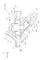
- FIG. 1 schematically shows the external configuration of the medical connector 10
- FIG. 2 shows its longitudinal section (YZ section).
- the medical connector 10 is a Y connector that is used by being connected to the guiding catheter GC via the rotator 20 .
- the side to which the guiding catheter GC is connected (positive Z-axis direction) is called the distal side
- the opposite side negative Z-axis direction
- the distal end is referred to as the “distal end”, the distal end and its vicinity as the “distal portion”, and the proximal end as the “basal end”.
- the end and the vicinity thereof are referred to as the "base end”.
- the Z-axis direction is also called the front-rear direction
- the Y-axis direction is also called the vertical direction
- the Y-axis positive direction is also called the upward direction
- the Y-axis negative direction is also called the downward direction
- the X-axis direction is also called the horizontal direction.
- the orientation of the medical connector 10 is not limited to this.
- the configuration of the side surfaces of some members may be omitted.
- the medical connector 10 has a tubular main pipe portion 11 extending in the front-rear direction, and a tubular branch pipe portion 12 branching from the vicinity of the distal end portion and obliquely extending upward toward the base end side.
- the main tube portion 11 is formed with a lumen 13 that extends in the front-rear direction and penetrates the main tube portion 11 . is introduced into the guiding catheter GC.
- the branch tube portion 12 is formed with a lumen 14 that communicates with the lumen 13 of the main tube portion 11 . Via 14 liquid agents, for example contrast media or saline, are supplied.
- the medical connector 10 includes a hemostasis valve opening/closing mechanism 100 and a long medical device fixing mechanism 200 .
- the opening/closing mechanism 100 is provided closer to the proximal side than the fixing mechanism 200 .
- the opening/closing mechanism 100 constitutes a portion of the base end side of the main pipe portion 11 of the medical connector 10
- the fixing mechanism 200 connects a portion of the distal end side of the main pipe portion 11 of the medical connector 10 and the branch pipe portion 12 .
- Configure The configurations of the opening/closing mechanism 100 and the fixing mechanism 200 will be described in order below.
- the medical connector 10 is held and used by an operator such as a doctor, for example.
- an operator holds the main tube portion 11 of the medical connector 10 in the posture shown in FIG.
- the medical connector 10 is grasped so as to be positioned near the operating member 280 .
- FIG. 3 shows its longitudinal section (YZ section), and FIGS. 4 and 5 show its perspective views.
- 3 and 4 show the opening/closing mechanism 100 with the hemostatic valve 120 closed (hereinafter referred to as "closed-state opening/closing mechanism 100c")
- FIG. 5 shows the hemostatic valve 120 in the opened state.
- the opening/closing mechanism 100 (hereinafter referred to as "open-state opening/closing mechanism 100o") is shown.
- the opening/closing mechanism 100 is a mechanism for opening/closing a hemostatic valve 120 that suppresses the outflow of blood through the lumen 13 of the main pipe portion 11 (FIG. 2) of the medical connector 10.
- the opening/closing mechanism 100 is a mechanism that switches the hemostatic valve 120 between a closed state and an open state each time the operating member 180 is pressed by the operator.
- the opening/closing mechanism 100 includes a housing 110 , a hemostatic valve 120 , a penetrating member 130 , an operating member 180 , a force transmission member 140 and a holding mechanism 160 .
- the housing 110 is a tubular member having a distal opening 112 and a proximal opening 111 and a lumen 113 communicating between the distal opening 112 and the proximal opening 111 .
- the lumen 113 is a through-hole extending in the front-rear direction (Z-axis direction) and constitutes part of the lumen 13 of the main tube portion 11 of the medical connector 10 .
- the housing 110 is made of resin, for example. As shown in FIG. 2, the proximal end of the fixing mechanism 200 is inserted and fixed in the lumen 113 .
- the Z-axis direction is an example of a first direction in the scope of claims.
- the housing 110 is composed of a distal housing portion 110D and a proximal housing portion 110P.
- Each of the distal housing portion 110D and the proximal housing portion 110P is a tubular member formed with a lumen extending in the front-rear direction.
- a substantially flat plate-like partition wall 114 that is substantially perpendicular to the front-rear direction is formed by the wall portion of the proximal end of the distal housing portion 110D.
- the partition 114 is formed with a through hole 114 ⁇ /b>A that penetrates the partition 114 in the front-rear direction and constitutes a part of the lumen 113 .
- the cross-sectional shape of 114 A of through-holes is substantially circular, for example. 4 and 5, illustration of the distal housing portion 110D is omitted.
- FIG. 6 is a cross-sectional perspective view showing the configuration of the base end side housing portion 110P that constitutes the housing 110 in the first embodiment.
- a guide groove 115 extending in the front-rear direction is formed in the inner side surface of the proximal housing portion 110P.
- a pair of guide grooves 115 are formed so as to face each other in the left-right direction (X-axis direction).
- a member accommodating space 116 that communicates with the lumen 113, extends obliquely downward to the proximal side, and opens onto the surface of the proximal housing portion 110P. is formed.
- the hemostatic valve 120 is a substantially disk-shaped member made of an elastic material such as silicone rubber.
- the hemostasis valve 120 is fixed inside the housing 110 at a position distal to the partition wall 114 .
- a slit 121 is formed at a substantially central position in the hemostasis valve 120 as viewed in the Z-axis direction (FIG. 4).
- Hemostasis valve 120 is normally in a closed state in which slit 121 is closed and the valve is closed (FIGS. 3 and 4).
- lumen 113 is closed by hemostasis valve 120 , and outflow of blood from hemostasis valve 120 to the proximal side through lumen 113 is suppressed.
- each piece divided by the slit 121 is elastically deformed so as to be displaced toward the distal side, forming a through hole 122 that penetrates the hemostatic valve 120 in the front-rear direction. It will be in the closed open state (Fig. 5).
- a through hole 122 formed in the hemostatic valve 120 in the open state communicates with the distal opening 112 via the lumen 113 . Therefore, when the hemostasis valve 120 is in the open state, the lumen 113 is not closed at the position of the hemostasis valve 120 and is in an open state.
- the hemostatic valve 120 elastically deforms and returns to the closed state.
- FIG. 7 is a perspective view showing the external configuration of the penetrating member 130 and the force transmission member 140 in the first embodiment.
- the penetrating member 130 is a member in which a through hole 132 extending in the front-rear direction is formed, and is made of resin, for example. More specifically, the penetrating member 130 includes a substantially cylindrical body portion 131 having a through hole 132 extending in the front-rear direction, and a substantially flat plate-like main body portion 131 that protrudes downward from the vicinity of the center in the front-rear direction and is substantially perpendicular to the front-rear direction. and a flange portion 133 .
- a pair of guide projections 134 projecting in the left-right direction are formed on the side surface of the flange portion 133, and a continuous guide projection 135 extending in the vertical direction is formed on the proximal surface of the flange portion 133. ing.
- the vertical direction is an example of a third direction in the scope of claims.
- the penetrating member 130 is accommodated in the housing 110 closer to the proximal side than the hemostatic valve 120 .
- a through hole 132 in the through member 130 communicates with the proximal opening 111 of the housing 110 . Also, through hole 132 and lumen 113 of housing 110 are coaxial with each other.
- a pair of guide projections 134 ( FIG. 7 ) formed on the flange portion 133 are fitted into a pair of guide grooves 115 ( FIG. 6 ) formed on the housing 110 .
- the penetrating member 130 is slidable in the front-rear direction using the guide groove 115 as a guide in a state in which the vertical and horizontal positions of the penetrating member 130 are determined with respect to the housing 110 .
- Penetrating member 130 is positioned such that body portion 131 thereof faces through hole 114A of partition wall 114 in the front-rear direction.
- the penetrating member 130 which is slidable in the front-rear direction, is inserted into the through hole 114A at the tip of the main body 131, and presses the hemostatic valve 120 to open the hemostatic valve 120. and a non-pressing position P1 in which the hemostatic valve 120 is closed without pressing the .
- the through hole 122 formed in the hemostatic valve 120 and the through hole 132 of the penetrating member 130 communicate with each other.
- Penetrating member 130 is movable to a position where flange portion 133 contacts partition wall 114 of housing 110 on the distal end side, and the proximal end of penetrating member 130 is located at the proximal end portion of housing 110 on the proximal end side. can be moved to a position where it abuts on a convex portion 119 (FIGS. 3 and 6) formed on the .
- the pressing position P2 of the penetrating member 130 is an example of the second position in the claims, and the non-pressing position P1 of the penetrating member 130 is an example of the first position in the claims.
- FIG. 8 is a perspective view showing the external configuration of the operation member 180 and the holding mechanism 160 in the first embodiment.
- the operation member 180 is a substantially cylindrical member extending in a direction (hereinafter referred to as "operation direction D2") non-parallel to the front-rear direction (Z-axis direction).
- operation direction D2 is a direction with an angle of 35 degrees or more and 55 degrees or less with the front-rear direction, for example, a direction with an angle of 45 degrees with the front-rear direction, i. This is the oblique direction of 45 degrees toward the proximal side.
- the operation member 180 is supported by an outer cylinder 150 of a holding mechanism 160, which will be described later, and is slidable along the operation direction D2. A portion of the base end side of the operation member 180 is exposed from the outer tube 150, and can be pressed by an operator such as a doctor.
- the operation member 180 is made of resin, for example.
- the operation direction D2 is an example of a second direction in the claims.
- the force transmission member 140 is a substantially polygonal member and is made of resin, for example.
- a distal end surface 143 of the force transmission member 140 has a planar shape substantially orthogonal to the front-rear direction, and is in contact with the proximal surface of the flange portion 133 of the penetrating member 130 .
- a guide groove 144 continuously extending in the vertical direction is formed in the tip surface 143 .
- a guide protrusion 135 of the penetrating member 130 is fitted in the guide groove 144 .
- a concave portion 145 capable of accommodating the base end portion of the body portion 131 of the penetrating member 130 is formed on the upper surface of the force transmission member 140 .
- a protruding portion 142 is formed on the surface of the force transmission member 140 on the lower base end side.
- the force transmission member 140 is housed in the member housing space 116 of the housing 110 so as to be positioned between the penetrating member 130 and the operation member 180, and is slidable along the operation direction D2.
- the force transmission member 140 can transmit to the penetrating member 130 a force that moves the operating member 180 toward the penetrating member 130 along the operating direction D2.
- the force transmission member 140 can slide relative to the penetration member 130 along the vertical direction while contacting the proximal surface of the flange portion 133 of the penetration member 130 . That is, as shown in FIGS. 3 and 4, when the penetrating member 130 is at the non-pressing position P1 in which the hemostatic valve 120 is not pressed, the force transmission member 140 is at the retracted position P3 retracted downward to the proximal side. . The force transmission member 140 does not press the penetrating member 130 when the force transmission member 140 is at the retracted position P3. When the penetrating member 130 is not pressed by the force transmission member 140, the penetrating member 130 is positioned at the non-pressing position P1.
- the retracted position P3 of the force transmission member 140 is an example of a third position in the claims.
- the holding mechanism 160 (FIG. 8) employs a so-called double knock mechanism, and each time the operation member 180 slides along the operation direction D2, the force transmission member 140 is held at the retracted position P3, or The state is switched to the state in which the force transmission member 140 is held at the forward position P4.
- the holding mechanism 160 has an outer cylinder 150 , a rotor 170 and a biasing member 162 . Note that, in the present embodiment, part of the operating member 180 also constitutes part of the holding mechanism 160 .
- FIG. 9 is a perspective view showing the external configuration of the outer cylinder 150 in the first embodiment.
- the outer cylinder 150 is a substantially cylindrical member and is made of resin, for example.
- the outer cylinder 150 is attached to the tip of the portion of the housing 110 where the member accommodating space 116 is formed, with the axial direction thereof aligned with the operation direction D2.
- a toothed outer cylinder end face cam 153 is formed on the inner peripheral surface of the outer cylinder 150 .
- the outer cylinder end surface cam 153 is a cam in which shallow groove portions 154 and deep groove portions 155 are alternately formed in the circumferential direction.
- the outer cylinder end face cam 153 is composed of four shallow groove portions 154 and four deep groove portions 155 .
- a tooth-shaped operating member end face cam 182 is formed on the end face of the substantially cylindrical operating member 180 on the upper tip side. Further, on the outer peripheral surface of the operation member 180, a plurality of (four) sliding contacts 181, which are substantially rectangular parallelepiped projections, are formed.
- the operating member 180 is inserted into the hollow portion of the outer cylinder 150 , and the sliding contacts 181 on the outer peripheral surface of the operating member 180 are fitted into the deep grooves 155 on the inner peripheral surface of the outer cylinder 150 .
- the operation member 180 is slidable relative to the outer cylinder 150 in the axial direction of the outer cylinder 150, that is, along the operation direction D2, while the rotation thereof is restricted.
- the rotor 170 is a substantially disk-shaped member and is made of resin, for example.
- a plurality of (four) protrusions 173 are formed on the outer peripheral surface of the rotor 170 . Teeth are formed on the surface on the lower base end side of each projection 173 of the rotor 170 .
- the pitch of the ridges of the operating member end cam 182 of the operating member 180 is shifted by about 1/2 from the pitch of the ridges of the outer cylinder end cam 153 of the outer cylinder 150 .
- Each projection 173 is structured so that it cannot mesh with both the operating member end face cam 182 and the outer cylinder end face cam 153 at the same time.
- a concave portion 174 is formed in the upper tip side surface of the rotor 170 .
- the biasing member 162 is a substantially cylindrical spring and is made of metal such as stainless steel.
- the biasing member 162 is arranged between the rotor 170 and the force transmission member 140 (FIG. 7), and biases the force transmission member 140 toward the outside of the housing 110 along the operation direction D2.
- One end of the biasing member 162 is inserted into the recess 174 of the rotor 170 , and the projection 142 of the force transmission member 140 is inserted into the hollow portion of the other end of the biasing member 162 .
- the rotor 170 In the rotor retracted state in which the protruding portions 173 of the rotor 170 are fitted into the deep groove portions 155 of the outer cylinder end surface cam 153 of the outer cylinder 150, the rotor 170 is retracted downward to the base end side using the deep groove portions 155 as guides. Located in Therefore, in the rotor retracted state, as shown in FIGS. 3 and 4, the force transmission member 140 is located at the retracted position P3 in which the force transmission member 140 is retracted toward the lower base end side, and as a result, the penetrating member 130 is located at the non-pressing position P1. do. The rotor retracted state is maintained as long as the operating member 180 does not slide.
- each convex portion 173 is fitted into the shallow groove portion 154 of the outer cylinder end surface cam 153 of the outer cylinder 150, not the deep groove portion 155. .
- the rotor 170 is held at a position advanced to the upper tip side compared to the rotor retreated state in which the deep grooves 155 are fitted. Therefore, in the rotor advance state, as shown in FIG. 5, the force transmission member 140 advances to the advance position P4, and as a result, the penetrating member 130 moves to the pressing position P2. As long as the operating member 180 does not slide, the rotor advance state is maintained.
- each convex portion 173 is fitted into the deep groove portion 155 of the outer cylinder end surface cam 153 instead of the shallow groove portion 154 .
- the holding mechanism 160 returns to the rotor retracted state, the force transmission member 140 retracts to the retracted position P3, and the penetrating member 130 moves to the non-pressing position P1. In this manner, the holding mechanism 160 changes the state of the force transmission member 140 to the retracted position P3 or the forward position P3 each time the operation member 180 slides along the operation direction D2. It switches to the state held at P4.
- FIGS. 3 and 4 Operation of the opening/closing mechanism 100: Next, the operation of the opening/closing mechanism 100 of the hemostatic valve 120 will be described.
- the holding mechanism 160 In the initial state, as shown in FIGS. 3 and 4, the holding mechanism 160 is in the rotor retracted state. In this state, the force transmission member 140 is located at the retracted position P3, and the penetrating member 130 is not pressed by the force transmission member 140 and is located at the non-pressing position P1. Therefore, the hemostasis valve 120 is closed, and the opening/closing mechanism 100 is a closed state opening/closing mechanism 100c.
- valve opening operation For example, an operation of pressing the operation member 180 toward the inside of the housing 110 (that is, obliquely upward) along the operation direction D2 with the thumb of the operator holding the medical connector 10 (hereinafter referred to as "valve opening operation"). ) is applied, the operating member 180 slides obliquely upward along the operating direction D2. Accordingly, the holding mechanism 160 switches from the rotor backward state to the rotor forward state. In this state, as shown in FIG. 5, the force transmission member 140 is positioned at the forward position P4, and the penetrating member 130 is pressed by the force transmission member 140 and positioned at the pressing position P2. As a result, the distal end portion of the main body portion 131 of the penetrating member 130 presses the hemostatic valve 120 to open the hemostatic valve 120, and the opening/closing mechanism 100 becomes the open state opening/closing mechanism 100o.
- opening/closing mechanism 100 when the opening/closing mechanism 100 is in the open state opening/closing mechanism 100o, for example, the operator's thumb moves toward the inside of the housing 110 along the operation direction D2 with respect to the operation member 180 in the same manner as the valve opening operation.
- a pressing operation ie, obliquely upward
- valve closing operation a pressing operation
- the operating member 180 slides obliquely upward along the operation direction D2.
- the holding mechanism 160 switches from the rotor advance state to the rotor retreat state. In this state, as shown in FIGS.
- the force transmission member 140 is positioned at the retracted position P3, and the penetrating member 130 is not pressed by the force transmission member 140 and returns to the non-pressing position P1.
- the penetrating member 130 closes the hemostatic valve 120 without pressing the hemostatic valve 120, and the opening/closing mechanism 100 becomes the closed state opening/closing mechanism 100c.
- the holding mechanism 160 holds the force transmission member 140 at the retracted position P3, or the force transmission member 140 is held at the retracted position P3 every time the operation member 180 slides along the operation direction D2. 140 is held at the forward position P4.
- the holding mechanism 160 switches to the state where the force transmission member 140 is held at the forward position P4, the penetrating member 130 moves from the non-pressing position P1 to the pressing position P2, and the hemostatic valve 120 switches from the closed state to the open state.
- the holding mechanism 160 holds the force transmission member 140 at the advanced position P4, so that the hemostatic valve 120 is kept open.
- the holding mechanism 160 switches to the state in which the force transmission member 140 is held at the retracted position P3 as the operation member 180 slides again, the penetrating member 130 moves from the pressing position P2 to the non-pressing position P1, and the hemostatic valve is closed. 120 switches from open to closed. At this time, the holding mechanism 160 holds the force transmission member 140 at the retracted position P3, so that the hemostatic valve 120 is kept closed.
- the operation member 180 is slidable along the operation direction D2 that is non-parallel to the extending direction (Z-axis direction) of the lumen 113 of the housing 110.
- the opening/closing operation of the hemostatic valve 120 This is an operation of pressing the operating member 180 in the operating direction D2 that is non-parallel to the extending direction of the lumen 113 . Therefore, according to the opening/closing mechanism 100, the operator can easily open/close the hemostatic valve 120 with the thumb while holding the medical connector 10, and the operability of the opening/closing mechanism 100 can be improved. .
- the holding mechanism 160 has a cylindrical biasing member 162 that biases the force transmission member 140 toward the outside of the housing 110 along the operation direction D2, and faces the biasing member 162 of the force transmission member 140.
- a convex portion 142 is formed on the surface to be inserted into the hollow portion of the biasing member 162 . Therefore, according to the opening/closing mechanism 100, the force transmission member 140 and the biasing member 162 can be positioned easily and accurately, and the biasing force of the biasing member 162 can be effectively transferred to the force transmission member 140. , and the accuracy of the operation of the opening/closing mechanism 100 can be improved.
- the angle formed by the extension direction (Z-axis direction) of the lumen 113 of the housing 110 and the operation direction D2 of the operation member 180 is 35 degrees or more and 55 degrees or less. Therefore, according to the opening/closing mechanism 100, the operating member 180 can be very easily operated by the operator's thumb while holding the medical connector 10, thereby effectively improving the operability of the opening/closing mechanism 100. be able to.
- the penetrating member 130 has a main body portion 131 in which a through hole 132 is formed, and a flange portion 133 projecting vertically from the main body portion 131 . It is configured to be slidable relative to the penetrating member 130 along the vertical direction while abutting on the side surface. Therefore, according to the opening/closing mechanism 100, the force transmission member 140 slides along the operation direction D2 that is non-parallel to the extending direction (Z-axis direction) of the lumen 113 of the housing 110, and the penetrating member 130 slides along the extending direction. (Z-axis direction) sliding can be efficiently converted, and the operability of the opening/closing mechanism 100 can be effectively improved.
- FIG. 10 is an explanatory diagram showing the configuration of a modification (opening/closing mechanism 100X) of the opening/closing mechanism 100 of the first embodiment.
- the opening/closing mechanism 100X differs from the opening/closing mechanism 100 in that the operation member 180 and the force transmission member 140 are integral members.
- a connecting shaft 147 extends from the lower proximal side surface of the force transmission member 140 toward the lower proximal side, and the connecting shaft 147 passes through a through hole 179 formed in the rotor 170 to operate. It extends to the member 180 and is connected to the operating member 180 .
- the operation member 180 and the force transmission member 140 are integrated and slide along the operation direction D2.
- the biasing member 162 is arranged substantially parallel to the front-rear direction between the front end side surface of the lower portion of the flange portion 133 of the penetrating member 130 and the housing 110 .
- the biasing member 162 indirectly biases the force transmission member 140 toward the outside of the housing 110 along the operation direction D2 by biasing the penetrating member 130 toward the base end side.
- the holding mechanism 160 holds the force transmission member 140 at the retracted position P3, or holds the force transmission member 140 at the retracted position P3. , the state where the member 140 is held at the forward position P4. Therefore, the operability of the opening/closing mechanism 100X can be similarly improved by the opening/closing mechanism 100X.
- FIG. 11 and 12 are explanatory diagrams showing the configuration. 11 and 12 show the structure of the longitudinal section (YZ section). 11 shows the fixing mechanism 200 (hereinafter referred to as “released state fixing mechanism 200n”) in which the fixation of the long medical device such as the guide wire GW is released, and FIG.
- the fixing mechanism 200 (hereinafter referred to as “fixed state fixing mechanism 200f”) is shown in a state where the scale-shaped medical device is fixed.
- the fixing mechanism 200 is a mechanism for fixing and releasing the fixation of the elongated medical device inserted through the lumen 13 of the main tube portion 11 (FIG. 2) of the medical connector 10 . Each time the operating member 280 is pressed by the operator, the fixing mechanism 200 is in a fixed state in which the elongated medical device is fixed, or in an unfixed state in which the fixed lengthy medical device is released. It is a mechanism that switches to The fixing mechanism 200 includes a housing 210 , a tubular body 290 , a pressing member 240 , an operating member 280 , a force transmission member 230 and a holding mechanism 260 .
- the housing 210 is a tubular member having a distal opening 212 and a proximal opening 211 and a lumen 213 communicating between the distal opening 212 and the proximal opening 211 .
- the lumen 213 is a through hole extending in the front-rear direction (Z-axis direction) and constitutes a part of the lumen 13 of the medical connector 10 .
- the housing 210 is made of resin, for example.
- a branch pipe portion 12 is formed at the distal end portion of the housing 210 .
- the proximal end of the housing 210 is inserted into and fixed to the lumen 113 at the distal end of the housing 110 of the opening/closing mechanism 100 .
- the proximal end portion of the housing 210 restricts movement of the hemostatic valve 120 toward the distal side.
- a cylindrical body accommodation space 215 which is a portion of the lumen 213 whose diameter is enlarged.
- a retraction space 214 is formed above the cylindrical body housing space 215 and communicates with the vicinity of the center in the front-rear direction.
- a member accommodation space 216 is formed that communicates with the vicinity of the center in the front-rear direction, extends obliquely toward the lower base end side, and opens onto the surface of the housing 210. As shown in FIG.
- FIG. 13 is a cross-sectional perspective view showing the configuration of the circular tubular body 290, the pressing member 240 and the force transmission member 230 in the first embodiment.
- the tubular body 290 is a flexible tubular member having a through hole 291 into which an elongated medical device such as a guide wire GW is inserted.
- the tubular body 290 is made of an elastic material such as silicone rubber.
- the tubular body 290 is mounted in the tubular body housing space 215 in such a posture that its axis is parallel to the front-rear direction (Z-axis direction).
- the through hole 291 communicates with the distal opening 212 and the proximal opening 211 of the housing 210 .
- the through hole 291 and the lumen 213 of the housing 210 are coaxial with each other.
- the front-rear direction (Z-axis direction) is an example of a fifth direction in the scope of claims.
- each stopper 220 includes a main body portion 221 having approximately the same diameter as the circular tubular body 290, a first small diameter portion 223 positioned on the circular tubular body 290 side with respect to the main body portion 221 and having a diameter smaller than that of the main body portion 221, and a main body portion 221.
- a second small-diameter portion 222 having a diameter smaller than that of the main body portion 221 is located on the opposite side of the circular tubular body 290 .
- the first small diameter portion 223 of each stopper 220 is inserted into the through hole 291 of the tubular body 290 .
- each stopper 220 is formed with a concave portion 224 into which a convex portion (not shown) of the housing 210 is fitted.
- Each stopper 220 is positioned in the longitudinal direction with respect to the housing 210 by fitting the convex portion and the concave portion 224 , and as a result, the cylindrical body 290 is positioned in the longitudinal direction with respect to the housing 210 .
- the pressing member 240 is a member in which a through hole 241 extending in the front-rear direction is formed, and is made of resin, for example.
- the pressing member 240 has a substantially rectangular parallelepiped shape, and the length (dimension in the front-rear direction) of the portion above the center position of the through hole 241 is longer than the other portions.
- the inner diameter of the through hole 241 of the pressing member 240 is substantially the same as the outer diameter of the tubular body 290 , and the tubular body 290 is inserted into the through hole 241 .
- the lower surface 244 of the pressing member 240 is a substantially flat surface that is substantially perpendicular to the vertical direction, and has a guide convex portion 245 that continuously extends in the front-rear direction.
- the pressing member 240 is housed across the evacuation space 214 , the cylindrical body housing space 215 and the member housing space 216 of the housing 210 .
- the pressing member 240 is slidable along the vertical direction (Y-axis direction), which is a direction orthogonal to the axial direction (Z-axis direction) of the tubular body 290 .
- the vertically slidable pressing member 240 has a non-pressing position P5 where the through hole 241 of the pressing member 240 is coaxial with the through hole 291 of the cylindrical body 290 as shown in FIG. and a pressing position P6 displaced upward from the non-pressing position P5.
- the pressing member 240 is positioned at the non-pressing position P5 (FIG.
- the pressing member 240 does not substantially press the cylindrical body 290.
- the state in which the pressing member 240 is not substantially pressed means a state in which the inner peripheral surface of the through hole 241 of the pressing member 240 and the outer peripheral surface of the tubular body 290 are separated from each other, and the through hole 241 of the pressing member 240 is not pressed. Since the inner diameter is the same as or slightly smaller than the outer shape of the cylindrical body 290 before being inserted into the through hole 241, the inner peripheral surface of the through hole 241 of the pressing member 240 and the outer peripheral surface of the cylindrical body 290 are in close contact. including the state of being The vertical direction (Y-axis direction) is an example of a sixth direction in the claims, and the non-pressing position P5 is an example of a fifth position in the claims.
- the pressing member 240 presses a portion of the cylindrical body 290 excluding both end portions (in this embodiment, the center portion in the front-rear direction) upward from the outer peripheral side. to elastically deform the circular tubular body 290 .
- the inner peripheral surface of the elastically deformed cylindrical body 290 (mainly the contact point CP1, which is the lower portion of the inner peripheral surface of the deformed portion of the cylindrical body 290) is pressed against the elongated medical device.
- the retraction space 214 of the housing 210 has a sufficient size for the pressing member 240 to deform the cylindrical body 290 to the extent that the long medical device can be fixed.
- the pressed position P6 is an example of a sixth position in the claims.
- the operation member 280 is a substantially cylindrical member that extends in a direction (hereinafter referred to as "operation direction D7") that is not parallel to the front-rear direction (Z-axis direction).
- the operation direction D7 is a direction with an angle of 35 degrees or more and 55 degrees or less with the front-rear direction. 45-degree oblique direction toward the side).
- the operation member 280 is supported by an outer cylinder 250 of a holding mechanism 260, which will be described later, and is slidable along the operation direction D7. A portion of the base end side of the operation member 280 is exposed from the outer tube 250, and can be pressed by an operator such as a doctor.
- the operation member 280 is made of resin, for example.
- the operation direction D7 is an example of a seventh direction in the claims.
- the force transmission member 230 is a substantially polygonal member and is made of resin, for example.
- An upper surface 234 of the force transmission member 230 is a substantially flat surface that is substantially orthogonal to the vertical direction, and has a guide groove 235 that continuously extends in the front-rear direction.
- a guide protrusion 245 of the pressing member 240 is fitted in the guide groove 235 .
- a protruding portion 232 is formed on a surface 233 on the lower base end side of the force transmission member 230 .
- force transmission member 230 is housed within member housing space 216 of housing 210 so as to be positioned between pressing member 240 and operation member 280, and is positioned in operation direction D7. It is slidable along.
- the force transmission member 230 can transmit to the pressing member 240 a force that moves the operating member 280 closer to the pressing member 240 along the operation direction D7.
- the force transmission member 230 Since the force transmission member 230 is configured as described above, it can slide relative to the pressing member 240 in the front-rear direction (Z-axis direction) while contacting the lower surface 244 of the pressing member 240 . That is, as shown in FIG. 11, when the pressing member 240 is at the non-pressing position P5 where it does not press the cylindrical body 290, the force transmission member 230 is at the retracted position P7 retracted toward the lower proximal side. The force transmission member 230 does not press the pressing member 240 when the force transmission member 230 is at the retracted position P7. When the pressing member 240 is not pressed by the force transmission member 230, the elastic restoring force of the cylindrical body 290 positions the pressing member 240 at the non-pressing position P5.
- the retracted position P7 is an example of a seventh position in the claims.
- the force transmission member 230 slides obliquely upward along the operation direction D7 from the retracted position P7 and moves from the retracted position P7 to the advanced position P8 closer to the cylindrical body 290, , the force transmission member 230 slides toward the distal end side relative to the pressure member 240 while maintaining the state in which the guide protrusion 245 of the pressure member 240 is fitted in the guide groove 235 of the force transmission member 230. .
- the force transmission member 230 presses the pressing member 240 to position the pressing member 240 at the pressing position P6.
- the forward position P8 is an example of an eighth position in the claims.
- the holding mechanism 260 employs a so-called double knock mechanism. is held at the forward position P8.
- the holding mechanism 260 has an outer cylinder 250 , a rotor 270 and a biasing member 262 . Note that, in the present embodiment, part of the operating member 280 also constitutes part of the holding mechanism 260 . Since the configuration of the holding mechanism 260 is the same as the configuration of the holding mechanism 160 of the opening/closing mechanism 100 described above, description thereof will be omitted.
- the holding mechanism 260 is in the rotor retracted state.
- the force transmission member 230 is located at the retracted position P7, and the pressing member 240 is not pressed by the force transmission member 230 and is located at the non-pressing position P5.
- the elongated medical device such as the guide wire GW inserted through the lumen 213 of the housing 210 (the lumen 13 of the main tube portion 11) is not fixed. That is, the fixing mechanism 200 is a released state fixing mechanism 200n.
- fixing operation when an operation of pressing the operation member 280 obliquely upward along the operation direction D7 (hereinafter referred to as “fixing operation”) is applied by the thumb of the operator holding the medical connector 10, the operation member 280 is operated. It slides obliquely upward along the direction D7. Accordingly, the holding mechanism 260 switches from the rotor backward state to the rotor forward state. In this state, as shown in FIG. 12, the force transmission member 230 is positioned at the forward position P8, and the pressing member 240 is pressed by the force transmission member 230 and positioned at the pressing position P6.
- the circular tubular body 290 is pressed by the pressing member 240 and elastically deformed to fix the long medical device inserted through the lumen 213 of the housing 210 .
- the fixing mechanism 200 becomes a fixed state fixing mechanism 200f.
- the fixing mechanism 200 when the fixing mechanism 200 is in the fixed state fixing mechanism 200f, for example, an operator's thumb can press the operation member 280 obliquely upward along the operation direction D7 in the same manner as the fixing operation ( hereinafter referred to as "unlocking operation"), the operating member 280 slides obliquely upward along the operating direction D7.
- the holding mechanism 260 switches from the rotor advance state to the rotor retreat state. In this state, as shown in FIG. 11, the force transmission member 230 is positioned at the retracted position P7, and the pressing member 240 is not pressed by the force transmission member 230 and moved to the non-pressing position P5 by the elastic restoring force of the cylindrical body 290. return.
- the circular tubular body 290 is not pressed by the pressing member 240 and is not elastically deformed, so that the long medical device inserted through the lumen 213 of the housing 210 is released from fixation. As a result, the fixing mechanism 200 returns to the released state fixing mechanism 200n.
- the fixing mechanism 200 switches to the released state fixing mechanism 200n or the fixed state fixing mechanism 200f each time the operation member 280 is pressed (fixing operation and unlocking operation).
- the operation member 280 is slidable along the operation direction D7 that is non-parallel to the direction parallel to the axis of the cylindrical body 290 (the Z-axis direction). Therefore, the fixing operation and the fixing release operation of the long medical device are operations of pressing the operating member 280 in the operating direction D7 that is not parallel to the direction parallel to the axis of the circular tubular body 290 . Therefore, according to the fixing mechanism 200 of the present embodiment, the operator can fix and fix the long medical device by pressing the operation member 280 with the thumb while holding the medical connector 10 . The release can be realized, and the fixation condition of the elongated medical device can be grasped by touch and sight, so that the operability of the fixation mechanism 200 can be improved.
- the holding mechanism 260 has a cylindrical biasing member 262 that biases the force transmission member 230 toward the pressing member 240 .
- a protrusion 232 to be inserted is formed. Therefore, according to the fixing mechanism 200 of the present embodiment, the force transmission member 230 and the biasing member 262 can be positioned easily and accurately, and the biasing force of the biasing member 262 can be effectively applied. The force can be transmitted to the force transmission member 230, and the precision of the operation of the fixing mechanism 200 can be improved.
- the angle between the direction parallel to the axis of the circular tubular body 290 (the Z-axis direction) and the operating direction D7 of the operating member 280 is 35 degrees or more and 55 degrees or less. Therefore, according to the fixation mechanism 200 of the present embodiment, the operator can very easily operate the operation member 280 with the thumb while holding the medical connector 10, and the operability of the fixation mechanism 200 is improved. can be substantially improved.
- the force transmission member 230 is configured to be slidable relative to the pressing member 240 along the direction (Z-axis direction) parallel to the axis of the cylindrical body 290 while contacting the surface of the pressing member 240 .
- sliding of the force transmission member 230 along the operation direction D7 and sliding of the pressing member 240 along the vertical direction can be efficiently converted. , the operability of the fixing mechanism 200 can be effectively improved.
- FIG. 14 is an explanatory diagram showing the external configuration of the medical connector 10A according to the second embodiment.
- the same configurations as those of the medical connector 10 of the first embodiment described above are denoted by the same reference numerals, and descriptions thereof will be omitted as appropriate.
- the medical connector 10A includes an opening/closing mechanism 300 and a fixing mechanism 200.
- the configuration of the fixing mechanism 200 included in the medical connector 10A is the same as the configuration of the fixing mechanism 200 included in the medical connector 10 of the first embodiment. Therefore, below, the opening-and-closing mechanism 300 with which 10 A of medical connectors of 2nd Embodiment are provided is demonstrated.
- FIG. 15 to 17 are explanatory diagrams showing the configuration of the opening/closing mechanism 300.
- FIG. FIG. 15 shows the configuration of a longitudinal section (YZ section) of the opening/closing mechanism 300
- FIGS. 15 and 16 show the opening/closing mechanism 300 with the hemostatic valve 320 closed (hereinafter referred to as "closed-state opening/closing mechanism 300c")
- FIG. 17 shows the hemostatic valve 320 opened.
- the opening/closing mechanism 300 in the open state hereinafter referred to as "open opening/closing mechanism 300o" is shown.
- the opening/closing mechanism 300 is a mechanism for opening/closing a hemostatic valve 320 that suppresses the outflow of blood through the lumen 13 of the main pipe portion 11 (FIG. 14) of the medical connector 10A.
- the opening/closing mechanism 300 of the present embodiment is a mechanism that switches between the closed state of the hemostatic valve 320 and the opened state of the hemostatic valve 320 each time the operating member 380 is pressed by the operator. be.
- the opening/closing mechanism 300 includes a housing 310 , a hemostatic valve 320 , a penetrating member 330 , an operating member 380 , a force transmission member 340 and a holding mechanism 360 .
- FIG. 18 is a cross-sectional perspective view showing the configuration of the housing 310 in the second embodiment.
- the housing 310 is a tubular member having a distal opening 312 and a proximal opening 311 and a lumen 313 communicating between the distal opening 312 and the proximal opening 311 .
- a lumen 313 formed in the housing 310 is a through-hole extending in the front-rear direction (Z-axis direction) and forms part of the lumen 13 of the main tube portion 11 of the medical connector 10A.
- the housing 310 is made of resin, for example.
- the Z-axis direction is an example of a first direction in the scope of claims.
- a substantially flat plate-like partition wall 314 that is substantially perpendicular to the front-rear direction is formed inside the housing 310 near the center in the front-rear direction.
- the partition 314 is formed with a through hole 314 ⁇ /b>A that penetrates the partition 314 in the front-rear direction and constitutes a part of the lumen 313 .
- the cross-sectional shape of 314 A of through-holes is substantially circular, for example.
- a vertically extending member accommodating space 316 is formed inside the housing 310 on the base end side of the partition wall 314 .
- the member accommodation space 316 opens to the surface of the housing 110 at the top of the housing 110 .
- the hemostasis valve 320 is a member having the same configuration as the hemostasis valve 120 of the first embodiment.
- the hemostasis valve 320 is fixed inside the housing 310 at a position distal to the partition wall 314 .
- Hemostasis valve 320 is normally in a closed state in which slit 321 is closed and the valve is closed (FIGS. 15 and 16).
- the hemostatic valve 320 is in an open state in which a through hole 322 is formed to penetrate the hemostatic valve 320 in the front-rear direction (FIG. 17).
- a substantially annular boss 328 is arranged between the hemostatic valve 320 and the partition wall 314 of the housing 310 .
- FIG. 19 is a perspective view showing the external configuration of the penetrating member 330 and the force transmission member 340 in the second embodiment.
- the penetrating member 330 is a tubular member having a through hole 332 extending in the front-rear direction, and is made of resin, for example.
- a protrusion 335 is formed on the outer peripheral surface of the penetrating member 330 so as to protrude in the left-right direction (X-axis direction) perpendicular to both the front-rear direction and the up-down direction.
- Two protrusions 335 are provided, one on each side of the penetrating member 330 . In this embodiment, the positions of the two protrusions 335 are the same as viewed in the X-axis direction.
- the horizontal direction is an example of a fourth direction in the scope of claims.
- the penetrating member 330 is housed inside the housing 310 on the proximal side of the hemostatic valve 320 .
- the through hole 332 communicates with the proximal opening 311 of the housing 310 .
- the through hole 332 of the penetrating member 330 and the lumen 313 of the housing 310 are coaxial with each other.
- the penetrating member 330 housed in the housing 310 is slidable in the front-rear direction while being positioned vertically and horizontally with respect to the housing 310 .
- Penetrating member 330 is positioned to face through hole 314A of partition wall 314 in the front-rear direction.
- the penetrating member 330 which is slidable in the front-rear direction, has its distal end inserted into the through hole 314A, and presses the hemostatic valve 320 to open the hemostatic valve 320 (state shown in FIG. 17). , a non-pressing position P1 (the state shown in FIGS. 15 and 16) in which the hemostatic valve 320 is not pressed and the hemostatic valve 320 is closed. As shown in FIG.
- the through hole 322 formed in the hemostatic valve 320 and the through hole 332 of the penetrating member 330 communicate with each other.
- the pressing position P2 of the penetrating member 330 is an example of the second position in the claims, and the non-pressing position P1 of the penetrating member 330 is an example of the first position in the claims.
- the operating member 380 is a substantially cylindrical member extending in a direction (hereinafter referred to as "operating direction D2") non-parallel to the front-rear direction (Z-axis direction).
- the operation member 380 is supported by an outer cylinder 350 of a holding mechanism 360, which will be described later, and is slidable along the operation direction D2.
- the operating direction D2 is a vertical direction that forms an angle of approximately 90 degrees with the front-rear direction. In this specification, approximately 90 degrees means a range of about 90 degrees plus or minus 5 degrees.
- a portion of the base end side of the operation member 380 is exposed from the outer tube 350 and can be pressed by an operator such as a doctor.
- the operating member 380 is made of resin, for example.
- the operation direction D2 is an example of a second direction in the claims.
- the force transmission member 340 is a substantially rectangular parallelepiped member, and is made of resin, for example.
- a through hole 344 extending in the front-rear direction is formed in the force transmission member 340 , and the through member 330 is inserted through the through hole 344 .
- Communication grooves 345 are formed in the left and right side surfaces of the force transmission member 340 to communicate the outer peripheral surface of the force transmission member 340 and the through holes 344 .
- Each communication groove 345 extends in a direction orthogonal to the left-right direction and non-parallel to both the front-rear direction and the up-down direction. More specifically, each communication groove 345 extends in a direction from the lower proximal side toward the upper distal side.
- each communication groove 345 with respect to the front-rear direction is, for example, 45 degrees.
- Each projection 335 of the penetrating member 330 is slidably inserted into each communication groove 345 . This allows the penetrating member 330 to slide relative to the force transmitting member 340 along the extending direction of the communication groove 345 .
- a projecting portion 343 protruding upward is formed on the upper surface of the force transmission member 340 .
- a projecting portion 342 projecting downward is formed on the lower surface of the force transmission member 340 .
- the force transmission member 340 is slidably accommodated in the member accommodation space 316 of the housing 310 along the operation direction D2.
- a biasing member 362 is arranged below the force transmission member 340 in the housing 310, and the biasing member 362 biases the force transmission member 340 upward.
- One end of the biasing member 362 is fixed to the bottom surface of the member accommodation space 316 of the housing 310, and the convex portion 342 (FIG. 19) of the force transmission member 340 is provided in the hollow portion of the other end of the biasing member 362. is inserted.
- the force transmission member 340 can transmit to the penetrating member 330 a force that moves the operating member 380 toward the penetrating member 330 along the operating direction D2. That is, as shown in FIGS. 15 and 16, when the force transmission member 340 is positioned at the retracted position P3 in which the force transmission member 340 is retracted upward, the protrusion 335 of the penetrating member 330 is positioned at the lower base end side of the communication groove 345 of the force transmission member 340. (hereinafter referred to as “closed position portion 345A”), whereby the penetrating member 330 is located at the proximal side position, that is, the non-pressing position P1 where the hemostatic valve 120 is not pressed.
- the retracted position P3 of the force transmission member 340 is an example of a third position in the claims.
- the force transmission member 340 receives the pressing force from the operation member 380 and moves downward along the operation direction D2 from the retracted position P3 to the forward position P4, the penetrating member 330
- the convex portion 335 relatively moves in the communication groove 345 of the force transmission member 340 to the upper tip side and reaches the upper tip portion (hereinafter referred to as “open position portion 345B”), thereby pressing the penetrating member 330. It moves to the position on the distal side, that is, the pressing position P2 where the hemostasis valve 120 is pressed to open.
- the forward position P4 of the force transmission member 340 is an example of a fourth position in the claims.
- the holding mechanism 360 (FIG. 15) is a so-called double-knock mechanism, and each time the operation member 380 slides along the operation direction D2, the force transmission member 340 is held at the retracted position P3, or the force transmission member 340 is held at the forward position P4.
- the holding mechanism 360 has an outer cylinder 350 and a rotor 370 .
- part of the operation member 380 and the biasing member 362 also constitute part of the holding mechanism 360 .
- the configuration of the holding mechanism 360 is the same as the configuration of the holding mechanism 160 of the opening/closing mechanism 100 of the first embodiment described above, so description thereof will be omitted. That is, in the description of the configuration of the holding mechanism 160 of the opening/closing mechanism 100 described above, if the outer cylinder 150 is replaced with the outer cylinder 350, the rotor 170 is replaced with the rotor 370, and the biasing member 162 is replaced with the biasing member 362, good.
- the biasing member 362 is arranged between the housing 310 and the force transmission member 340 as described above, rather than between the force transmission member 340 and the rotor 370 . The biasing member 362 biases the force transmission member 340 toward the outside of the housing 310 along the operation direction D2 even in such an arrangement.
- valve opening operation For example, an operation of pressing the operation member 380 toward the inside of the housing 310 (ie, downward) along the operation direction D2 with the index finger of the operator holding the medical connector 10A (hereinafter referred to as "valve opening operation"). is applied, the operating member 380 slides downward along the operating direction D2. Accordingly, the holding mechanism 360 switches from the rotor backward state to the rotor forward state. In this state, as shown in FIG. 17, the force transmission member 340 is displaced to the forward position P4, and the penetrating member 330 is pressed toward the distal end side by the force transmission member 340 and is displaced to the pressing position P2. As a result, the distal end of the penetrating member 330 presses the hemostatic valve 320 to open the hemostatic valve 320, and the opening/closing mechanism 300 becomes an open opening/closing mechanism 300o.
- the operation member 380 when the opening/closing mechanism 300 is in the open state opening/closing mechanism 300o, the operation member 380 is pressed toward the inside of the housing 310 (that is, downward) along the operation direction D2 in the same manner as the valve opening operation.
- valve closing operation When an operation (hereinafter referred to as "valve closing operation") is applied, the operation member 380 slides downward along the operation direction D2.
- the holding mechanism 360 switches from the rotor advance state to the rotor retreat state.
- the force transmission member 340 is displaced to the retracted position P3, and the penetrating member 330 returns to the non-pressing position P1 without being pushed toward the distal end side by the force transmission member 340. .
- the penetrating member 330 closes the hemostatic valve 320 without pressing the hemostatic valve 320, and the opening/closing mechanism 300 becomes the closed opening/closing mechanism 300c.
- the opening/closing mechanism 300 switches to the closed state opening/closing mechanism 300c or the open state opening/closing mechanism 300o each time the operation member 380 is pressed (valve opening operation and valve closing operation).
- the opening/closing mechanism 300 of the second embodiment has the same configuration as that of the first embodiment. Opening and closing operation can be easily performed, and the operability of the opening and closing mechanism 300 can be improved.
- the holding mechanism 360 has a cylindrical biasing member 362 that biases the force transmission member 340 toward the operating member 380.
- the surface facing the biasing member 362 has a hollow portion of the biasing member 362.
- a protrusion 342 to be inserted is formed. Therefore, according to the opening/closing mechanism 300 of the second embodiment, similarly to the opening/closing mechanism 100 of the first embodiment, positioning between the force transmission member 340 and the biasing member 362 can be performed easily and accurately.
- the biasing force of the biasing member 362 can be effectively transmitted to the force transmission member 340, and the accuracy of the operation of the opening/closing mechanism 300 can be improved.
- the angle formed by the extension direction (Z-axis direction) of the lumen 313 of the housing 310 and the operation direction D2 of the operation member 380 is approximately 90 degrees. Therefore, according to the opening/closing mechanism 300 of the second embodiment, the operator can very easily open/close the hemostatic valve 320 with the thumb or forefinger while holding the medical connector 10A. Operability can be effectively improved.
- the penetrating member 330 has a protrusion 335 that protrudes in the left-right direction, which is a direction perpendicular to both the extending direction (Z-axis direction) of the lumen 313 of the housing 310 and the operation direction D2.
- a communication groove 345 into which the projection 335 is inserted is formed.
- the communication groove 345 extends in a direction orthogonal to the left-right direction and non-parallel to both the extension direction (Z-axis direction) of the lumen 313 of the housing 310 and the operation direction D2.
- the sliding of the force transmission member 340 along the vertical direction substantially orthogonal to the extending direction of the lumen 313 of the housing 310 and the sliding of the penetrating member 330 in the extending direction are performed.
- the motion can be efficiently converted, and the operability of the opening/closing mechanism 300 can be effectively improved.
- FIG. 20 is an explanatory diagram showing a modified example (opening/closing mechanism 300X) configuration of the opening/closing mechanism 300 of the second embodiment.
- the opening/closing mechanism 300X of the modified example shown in FIG. 20 differs from the opening/closing mechanism 300 of the second embodiment described above in that the operation member 380 and the force transmission member 340 are integrated.
- a connecting shaft 347 extends upward from the upper surface of the force transmission member 340 . is connected with Therefore, in the opening/closing mechanism 300X of the modified example, the operation member 380 and the force transmission member 340 are integrally slid along the operation direction D2.
- the holding mechanism 360 holds the force transmission member 340 at the retracted position P3 or the forward position P4. , and switches to . Therefore, the operability of the opening/closing mechanism 300 can be similarly improved by the opening/closing mechanism 300X of the modified example.
- FIG. 21 is an explanatory diagram showing the structure of a longitudinal section (YZ section) of the medical connector 10B according to the third embodiment.
- the same configurations as those of the medical connector 10 of the first embodiment described above are denoted by the same reference numerals, and the description thereof will be omitted as appropriate.
- the medical connector 10B includes an opening/closing mechanism 100 and a fixing mechanism 200B.
- the opening/closing mechanism 100 provided in the medical connector 10B is the same as the opening/closing mechanism 100 provided in the medical connector 10 of the first embodiment, so description thereof will be omitted. do.
- FIG. 22 and 23 are explanatory diagrams showing the configuration of the fixing mechanism 200B, showing the configuration of its longitudinal section (YZ section).
- FIG. 22 shows the fixing mechanism 200B (released state fixing mechanism 200n) in which the fixation of the long medical device such as the guide wire GW is released
- FIG. 2 shows the fixing mechanism 200B in a closed state (fixed state fixing mechanism 200f). A side view of some members is shown.
- a fixing mechanism 200B of the third embodiment includes a circular tubular body 490 instead of the circular tubular body 290 in the fixing mechanism 200 of the first embodiment.
- the tubular body 490 differs from the tubular body 290 in the configuration of the through holes 491 . That is, the inner diameter of the through-hole 491 extending through the circular tubular body 490 in the longitudinal direction changes according to the position along the axial direction. More specifically, in the circular tubular body 490, the inner diameter d1a of the through hole 491 at the central portion 490a is smaller than the inner diameter d1b at the distal end portion 490b and smaller than the inner diameter d1c at the proximal end portion 490c.
- the through hole 491 is wider at the distal end and the proximal end than at the central portion. Therefore, the area S1a of the through-hole 491 in the cross section of the fixing mechanism 200B is equal to the area S1a of the through-hole 491 in the cross section of the central portion 490a (more specifically, the cross section of the fixing mechanism 200B (the same applies hereinafter)). It is smaller than the area S1b of the portion 490b and smaller than the area S1c of the base end portion 490c.
- the cross-sectional shape of the through-hole 491 at each position may take any shape, but is circular, for example.
- the through hole 491 is an example of a first through hole in the claims.
- Stoppers 420 are attached to the distal end and the proximal end of the tubular body 490 in the same manner as in the first embodiment.
- Each stopper 420 has a main body portion 421 having substantially the same outer diameter as the central portion 490 a of the circular tubular body 490 , and a second body portion 421 located on the circular tubular body 490 side with respect to the main body portion 421 and having a smaller outer diameter than the main body portion 421 .
- 1 small-diameter portion 423 and a second small-diameter portion 422 located on the opposite side of the main body portion 421 from the cylindrical body 490 and having an outer diameter smaller than that of the main body portion 421 .
- the first small diameter portion 423 is inserted into the through hole 491 .
- the main body portion 421 is formed with a concave portion 424 into which a convex portion (not shown) of the housing 210 is fitted.
- the stopper 420 is positioned in the front-rear direction with respect to the housing 210 by fitting the projection and the recess 424 , and as a result, the cylindrical body 490 is positioned in the front-rear direction with respect to the housing 210 .
- distal stop 420 connects distal end 490 b to housing 210 and proximal stop 420 connects proximal end 490 c to housing 210 .
- a through hole 425 communicating with the through hole 491 is formed in each stopper 420 .
- the shape of the through-hole 425 in the cross section at each portion may take any shape, but is circular, for example.
- the tip-side stopper 420 is an example of the tip-side connecting portion in the claims, and the through hole 425 of the tip-side stopper 420 is an example of the second through hole in the claims.
- the proximal-side stopper 420 is an example of a proximal-side connecting portion in the claims, and the through-hole 425 of the proximal-side stopper 420 is an example of a third through-hole in the claims. .
- the inner diameter d2 of the through hole 425 is larger than the inner diameter d1a of the through hole 491 in the central portion 490a. Therefore, the area S2 of the through hole 425 in the cross section of the first small diameter portion 423 of the stopper 420 on the distal end side is larger than the area S1a of the through hole 491 in the cross section of the central portion 490a of the cylindrical body 490 .
- the inner diameter d3 of the through-hole 425 in the first small-diameter portion 423 (the portion inserted into the through-hole 491 of the circular tubular body 490) of the stopper 420 on the proximal side is It is larger than the inner diameter d1a of the hole 491. Therefore, the area S3 of the through hole 425 in the cross section of the first small diameter portion 423 of the stopper 420 on the proximal end side is larger than the area S1a of the through hole 491 in the cross section of the central portion 490a of the tubular body 490 .
- the outer diameter at the central portion 490a is larger than the outer diameter at the distal end portion 490b and larger than the outer diameter at the proximal end portion 490c. Therefore, in the cylindrical body 490 housed in the substantially hollow columnar cylindrical body housing space 215 in the housing 210, the outer peripheral surface of the central portion 490a is in contact with or close to the inner peripheral surface of the cylindrical body housing space 215. On the other hand, the outer peripheral surfaces of the distal end portion 490 b and the proximal end portion 490 c are separated from the inner peripheral surface of the cylindrical body accommodating space 215 .
- a fixing mechanism 200B of the third embodiment includes a pressing member 440 instead of the pressing member 240 of the first embodiment.
- the pressing member 440 has a shape obtained by removing the portion above the through hole 241 of the pressing member 240 of the first embodiment. That is, the pressing member 440 is arranged below the central portion 490a of the tubular body 490, and in the released state described above, the upper surface of the pressing member 440 is in contact with or close to the outer peripheral surface of the central portion 490a of the tubular body 490.
- the pressing member 440 is slidable along the vertical direction (Y-axis direction) perpendicular to the axial direction (Z-axis direction) of the tubular body 490 .
- the vertically slidable pressing member 440 has a non-pressing position P5 at which it does not substantially press the cylindrical body 490 as shown in FIG. 22, and an upward displacement from the non-pressing position P5 as shown in FIG. and the pressing position P6.
- the state in which the pressing member 440 is not substantially pressed means that the upper surface of the pressing member 440 is in close contact with the outer peripheral surface of the tubular member 490 in addition to the state in which the upper surface of the pressing member 440 is separated from the outer peripheral surface of the tubular member 490. including the state of
- the pressing member 440 presses the central portion 490a of the cylindrical body 490 upward from the outer peripheral side to elastically deform the central portion 490a.
- the contact point CP1 which is the lower portion of the inner peripheral surface of the central portion 490a, which is the inner peripheral surface of the through hole 491 of the central portion 490a that is elastically deformed, and the upper portion of the inner peripheral surface of the central portion 490a.
- the contact points CP3 and are pressed against the elongated medical device, and the elongated medical device is clamped by the two contact points CP1 and CP3, thereby being fixed to the fixing mechanism 200B and restricted from sliding in the front-rear direction. be.
- the area S2 of the through hole 425 in the cross section of the first small diameter portion 423 of the stopper 420 on the distal side and the through hole in the cross section of the first small diameter portion 423 of the stopper 420 on the proximal side The area S3 of 425 is larger than the area S1a of the through hole 491 in the cross section of the central portion 490a of the circular tubular body 490 . Therefore, even when the pressing member 440 presses the central portion 490a of the circular tubular body 490 and the elongated medical device is fixed, the elongated medical device may not be pressed against the inner peripheral surface of the stopper 420.
- the configurations of the medical connector 10, the opening/closing mechanisms 100 and 300, and the fixing mechanism 200 in the above embodiment are merely examples, and various modifications are possible.
- the surface of the force transmission member 140 facing the biasing member 162 is formed with the protrusion 142 that is inserted into the hollow portion of the biasing member 162 . It does not have to be formed.
- the convex portion 232 of the force transmission member 230 and the convex portion 342 of the force transmission member 340 can be omitted.
- a so-called double knock mechanism is used as the holding mechanism 260 that switches between the state in which the force transmission member 230 is held in the retracted position P7 and the state in which the force transmission member 230 is held in the forward position P8.
- Other mechanisms such as a heart cam mechanism may be used as the holding mechanism 260 .
- holding mechanism 160 and/or holding mechanism 360 other mechanisms such as a heart cam mechanism may be used instead of the double knock mechanism.
- the housing 210 and the stoppers 220, 240 may be integral members.
- the medical connector 10 includes both the opening/closing mechanism 100 (or the opening/closing mechanism 300) and the fixing mechanism 200. and only one of
Landscapes
- Health & Medical Sciences (AREA)
- Heart & Thoracic Surgery (AREA)
- Life Sciences & Earth Sciences (AREA)
- Hematology (AREA)
- Anesthesiology (AREA)
- Biomedical Technology (AREA)
- Engineering & Computer Science (AREA)
- Pulmonology (AREA)
- Animal Behavior & Ethology (AREA)
- General Health & Medical Sciences (AREA)
- Public Health (AREA)
- Veterinary Medicine (AREA)
- Biophysics (AREA)
- Infusion, Injection, And Reservoir Apparatuses (AREA)
- Surgical Instruments (AREA)
Priority Applications (4)
| Application Number | Priority Date | Filing Date | Title |
|---|---|---|---|
| CN202280060915.4A CN117915982A (zh) | 2021-09-09 | 2022-08-08 | 止血阀的开闭机构、长条状医疗器具的固定机构以及医疗用接合管 |
| EP22867130.1A EP4400149A4 (en) | 2021-09-09 | 2022-08-08 | Opening/closing mechanism for hemostasis valve, fastening mechanism for long medical device and medical connector |
| JP2023546842A JP7629105B2 (ja) | 2021-09-09 | 2022-08-08 | 止血弁の開閉機構 |
| US18/598,229 US20240245895A1 (en) | 2021-09-09 | 2024-03-07 | Hemostasis valve assembly, apparatus for fixing elongate medical device, and medical connector |
Applications Claiming Priority (2)
| Application Number | Priority Date | Filing Date | Title |
|---|---|---|---|
| JP2021-146545 | 2021-09-09 | ||
| JP2021146545 | 2021-09-09 |
Related Child Applications (1)
| Application Number | Title | Priority Date | Filing Date |
|---|---|---|---|
| US18/598,229 Continuation US20240245895A1 (en) | 2021-09-09 | 2024-03-07 | Hemostasis valve assembly, apparatus for fixing elongate medical device, and medical connector |
Publications (1)
| Publication Number | Publication Date |
|---|---|
| WO2023037808A1 true WO2023037808A1 (ja) | 2023-03-16 |
Family
ID=85507527
Family Applications (1)
| Application Number | Title | Priority Date | Filing Date |
|---|---|---|---|
| PCT/JP2022/030210 Ceased WO2023037808A1 (ja) | 2021-09-09 | 2022-08-08 | 止血弁の開閉機構、長尺状医療機器の固定機構および医療用コネクタ |
Country Status (5)
| Country | Link |
|---|---|
| US (1) | US20240245895A1 (https=) |
| EP (1) | EP4400149A4 (https=) |
| JP (1) | JP7629105B2 (https=) |
| CN (1) | CN117915982A (https=) |
| WO (1) | WO2023037808A1 (https=) |
Families Citing this family (1)
| Publication number | Priority date | Publication date | Assignee | Title |
|---|---|---|---|---|
| EP4701704A1 (en) | 2023-04-27 | 2026-03-04 | Cultiv8 Medical, LLC | Introducer sheath systems and methods |
Citations (5)
| Publication number | Priority date | Publication date | Assignee | Title |
|---|---|---|---|---|
| JPH06238003A (ja) * | 1993-01-28 | 1994-08-30 | Cook Inc | カテーテルの先端形状制御装置 |
| US20030225379A1 (en) * | 2002-02-19 | 2003-12-04 | Medamicus, Inc. | Composite stasis valve |
| JP2005143647A (ja) * | 2003-11-12 | 2005-06-09 | Terumo Corp | 医療用コネクター |
| JP5249049B2 (ja) | 2006-12-26 | 2013-07-31 | 株式会社グツドマン | 止血弁を有するコネクタ |
| JP2013154067A (ja) * | 2012-01-31 | 2013-08-15 | Mc Co Ltd | コネクタ |
-
2022
- 2022-08-08 CN CN202280060915.4A patent/CN117915982A/zh not_active Withdrawn
- 2022-08-08 JP JP2023546842A patent/JP7629105B2/ja active Active
- 2022-08-08 EP EP22867130.1A patent/EP4400149A4/en active Pending
- 2022-08-08 WO PCT/JP2022/030210 patent/WO2023037808A1/ja not_active Ceased
-
2024
- 2024-03-07 US US18/598,229 patent/US20240245895A1/en not_active Abandoned
Patent Citations (5)
| Publication number | Priority date | Publication date | Assignee | Title |
|---|---|---|---|---|
| JPH06238003A (ja) * | 1993-01-28 | 1994-08-30 | Cook Inc | カテーテルの先端形状制御装置 |
| US20030225379A1 (en) * | 2002-02-19 | 2003-12-04 | Medamicus, Inc. | Composite stasis valve |
| JP2005143647A (ja) * | 2003-11-12 | 2005-06-09 | Terumo Corp | 医療用コネクター |
| JP5249049B2 (ja) | 2006-12-26 | 2013-07-31 | 株式会社グツドマン | 止血弁を有するコネクタ |
| JP2013154067A (ja) * | 2012-01-31 | 2013-08-15 | Mc Co Ltd | コネクタ |
Non-Patent Citations (1)
| Title |
|---|
| See also references of EP4400149A4 |
Also Published As
| Publication number | Publication date |
|---|---|
| EP4400149A4 (en) | 2025-11-05 |
| JPWO2023037808A1 (https=) | 2023-03-16 |
| US20240245895A1 (en) | 2024-07-25 |
| CN117915982A (zh) | 2024-04-19 |
| EP4400149A1 (en) | 2024-07-17 |
| JP7629105B2 (ja) | 2025-02-12 |
Similar Documents
| Publication | Publication Date | Title |
|---|---|---|
| JP5296274B1 (ja) | 内視鏡処置具 | |
| KR101086979B1 (ko) | 뼈 분리기 | |
| US8936595B2 (en) | Surgical instrument, particularly electrosurgical instrument | |
| KR20220054574A (ko) | 홈형 작동 레버를 갖춘 작동 메커니즘 | |
| US10206744B2 (en) | Waveguide locks and counterbalances for waveguide conduits | |
| JP4295628B2 (ja) | 分解可能にハウジングに配設された機能ユニットを結合するための装置 | |
| WO2023037808A1 (ja) | 止血弁の開閉機構、長尺状医療機器の固定機構および医療用コネクタ | |
| EP2083715B1 (en) | Removable handle for medical device | |
| WO2023037807A1 (ja) | 止血弁の開閉機構、長尺状医療機器の固定機構および医療用コネクタ | |
| JP2014155625A (ja) | カテーテルコネクタ | |
| JP5271798B2 (ja) | 超音波内視鏡用穿刺針装置 | |
| CN110461245B (zh) | 切割活检器械 | |
| JP7690359B2 (ja) | 止血弁の開閉機構および医療用コネクタ | |
| US9566081B2 (en) | Actuation grip for a microsurgical instrument, and microsurgical instrument | |
| JPWO2023037808A5 (https=) | ||
| JPWO2023037807A5 (https=) | ||
| TWI833484B (zh) | 鑽頭停止器 | |
| CN219516390U (zh) | 器械手柄和医疗器械 | |
| JP6369127B2 (ja) | 穿刺器具 | |
| CN217162375U (zh) | 髋臼杯扣打手柄 | |
| NL2034743B1 (en) | Surgical instrument | |
| CN118105148A (zh) | 手术穿刺引导器 | |
| EP2967753B1 (en) | Waveguide locks and counterbalances for waveguide conduits | |
| CN121221907A (zh) | 夹持机构以及可调弯鞘管 | |
| CN117731340A (zh) | 器械手柄和医疗器械 |
Legal Events
| Date | Code | Title | Description |
|---|---|---|---|
| 121 | Ep: the epo has been informed by wipo that ep was designated in this application |
Ref document number: 22867130 Country of ref document: EP Kind code of ref document: A1 |
|
| WWE | Wipo information: entry into national phase |
Ref document number: 2023546842 Country of ref document: JP |
|
| WWE | Wipo information: entry into national phase |
Ref document number: 202280060915.4 Country of ref document: CN |
|
| WWE | Wipo information: entry into national phase |
Ref document number: 2022867130 Country of ref document: EP |
|
| NENP | Non-entry into the national phase |
Ref country code: DE |
|
| ENP | Entry into the national phase |
Ref document number: 2022867130 Country of ref document: EP Effective date: 20240409 |