WO2023037808A1 - Opening/closing mechanism for hemostasis valve, fixing mechanism for long medical device, and medical connector - Google Patents
Opening/closing mechanism for hemostasis valve, fixing mechanism for long medical device, and medical connector Download PDFInfo
- Publication number
- WO2023037808A1 WO2023037808A1 PCT/JP2022/030210 JP2022030210W WO2023037808A1 WO 2023037808 A1 WO2023037808 A1 WO 2023037808A1 JP 2022030210 W JP2022030210 W JP 2022030210W WO 2023037808 A1 WO2023037808 A1 WO 2023037808A1
- Authority
- WO
- WIPO (PCT)
- Prior art keywords
- force transmission
- opening
- housing
- pressing
- transmission member
- Prior art date
Links
- 230000007246 mechanism Effects 0.000 title claims abstract description 363
- 230000023597 hemostasis Effects 0.000 title claims abstract description 45
- 230000005540 biological transmission Effects 0.000 claims abstract description 192
- 230000000149 penetrating effect Effects 0.000 claims description 109
- 230000002439 hemostatic effect Effects 0.000 claims description 88
- 230000002093 peripheral effect Effects 0.000 claims description 34
- 238000004891 communication Methods 0.000 claims description 12
- 230000000740 bleeding effect Effects 0.000 claims 1
- 238000010586 diagram Methods 0.000 description 16
- 238000005192 partition Methods 0.000 description 14
- 239000011347 resin Substances 0.000 description 14
- 229920005989 resin Polymers 0.000 description 14
- 210000003813 thumb Anatomy 0.000 description 14
- 230000004308 accommodation Effects 0.000 description 8
- 238000012986 modification Methods 0.000 description 6
- 230000004048 modification Effects 0.000 description 6
- 238000005516 engineering process Methods 0.000 description 5
- 239000008280 blood Substances 0.000 description 4
- 210000004369 blood Anatomy 0.000 description 4
- 230000000694 effects Effects 0.000 description 4
- 230000035515 penetration Effects 0.000 description 4
- 210000005224 forefinger Anatomy 0.000 description 3
- 238000013459 approach Methods 0.000 description 2
- 239000003795 chemical substances by application Substances 0.000 description 2
- 239000002872 contrast media Substances 0.000 description 2
- 239000013013 elastic material Substances 0.000 description 2
- 239000007788 liquid Substances 0.000 description 2
- 230000033001 locomotion Effects 0.000 description 2
- 229920002379 silicone rubber Polymers 0.000 description 2
- 239000004945 silicone rubber Substances 0.000 description 2
- FAPWRFPIFSIZLT-UHFFFAOYSA-M Sodium chloride Chemical compound [Na+].[Cl-] FAPWRFPIFSIZLT-UHFFFAOYSA-M 0.000 description 1
- 239000000470 constituent Substances 0.000 description 1
- 229940039231 contrast media Drugs 0.000 description 1
- 238000006073 displacement reaction Methods 0.000 description 1
- 210000003811 finger Anatomy 0.000 description 1
- 239000000463 material Substances 0.000 description 1
- 239000002184 metal Substances 0.000 description 1
- 239000002504 physiological saline solution Substances 0.000 description 1
- 230000015541 sensory perception of touch Effects 0.000 description 1
- 238000000926 separation method Methods 0.000 description 1
- 239000011780 sodium chloride Substances 0.000 description 1
- 239000007787 solid Substances 0.000 description 1
- 229910001220 stainless steel Inorganic materials 0.000 description 1
- 239000010935 stainless steel Substances 0.000 description 1
Images


Classifications
-
- A—HUMAN NECESSITIES
- A61—MEDICAL OR VETERINARY SCIENCE; HYGIENE
- A61M—DEVICES FOR INTRODUCING MEDIA INTO, OR ONTO, THE BODY; DEVICES FOR TRANSDUCING BODY MEDIA OR FOR TAKING MEDIA FROM THE BODY; DEVICES FOR PRODUCING OR ENDING SLEEP OR STUPOR
- A61M25/00—Catheters; Hollow probes
- A61M25/01—Introducing, guiding, advancing, emplacing or holding catheters
- A61M25/02—Holding devices, e.g. on the body
-
- A—HUMAN NECESSITIES
- A61—MEDICAL OR VETERINARY SCIENCE; HYGIENE
- A61M—DEVICES FOR INTRODUCING MEDIA INTO, OR ONTO, THE BODY; DEVICES FOR TRANSDUCING BODY MEDIA OR FOR TAKING MEDIA FROM THE BODY; DEVICES FOR PRODUCING OR ENDING SLEEP OR STUPOR
- A61M39/00—Tubes, tube connectors, tube couplings, valves, access sites or the like, specially adapted for medical use
- A61M39/02—Access sites
- A61M39/06—Haemostasis valves, i.e. gaskets sealing around a needle, catheter or the like, closing on removal thereof
Definitions
- the technology disclosed in this specification relates to a hemostatic valve opening/closing mechanism, a fixing mechanism for a long medical device, and a medical connector.
- a Y connector is a medical connector that is used by being connected to a guiding catheter.
- the Y connector has a main tube and a branch tube branched from the main tube.
- An elongated medical device such as a guide wire or a catheter is introduced into the guiding catheter through the main tube and branched.
- Liquid agents such as a contrast medium and physiological saline are supplied through the tube.
- the Y connector is provided with an opening/closing mechanism for opening and closing a hemostatic valve that suppresses the outflow of blood through the lumen of the main tube, and a fixing mechanism for fixing the long medical device.
- a penetrating member (opener) having a through hole coaxial with the lumen of the main pipe is provided.
- an open state in which the hemostatic valve is opened by the penetrating member pressing the hemostatic valve, and a closed state in which the hemostatic valve is closed by the penetrating member being separated from the hemostatic valve.
- an elastic fixing valve having a through hole through which the long medical device is inserted is provided.
- the operation of opening and closing the hemostatic valve is an operation of pressing the penetrating member in the axial direction of the lumen of the main tube, so there is a problem that the operation is difficult.
- fixing/unfixing the elongated medical device is an operation of rotating the screw. There is a problem that it is not possible to grasp the tactile sense or visually.
- This specification discloses a technology capable of solving the above-described problems.
- a hemostatic valve opening/closing mechanism disclosed in the present specification includes a housing, a hemostatic valve, a penetrating member, an operation member, a force transmission member, and a holding mechanism.
- the housing is a tubular member having a lumen that communicates with the distal opening and the proximal opening.
- the hemostatic valve is mounted in the housing and is normally in a closed state, and when pressed from the proximal end side, it is in an open state in which a through hole communicating with the distal end side opening of the housing is formed.
- the penetrating member is housed in the housing slidably along the first direction, which is the extending direction of the lumen, on the proximal side of the hemostatic valve.
- a through hole is formed in the through member to communicate with the base end side opening of the housing.
- the penetrating member has a first position in which the hemostasis valve is closed, and a position on the distal side of the first position along the first direction, and presses the hemostasis valve to close the hemostasis valve. a second position in which the hemostasis valve is in the open state and the through hole of the hemostasis valve and the through hole of the penetrating member are communicated with each other;
- the operating member is a member that can slide along a second direction that is non-parallel to the first direction.
- a force transmission member is disposed between the penetrating member and the operating member so as to be slidable in the second direction, and the operating member moves along the second direction so as to approach the penetrating member.
- the force transmission member can be positioned in a third position that positions the penetrating member in the first position and in a fourth position that presses the penetrating member to position the penetrating member in the second position.
- the holding mechanism holds the force transmission member at the third position or holds the force transmission member at the fourth position each time the operation member slides in the second direction. It is a mechanism that switches to the held state.
- the holding mechanism holds the force transmission member at the third position or holds the force transmission member at the fourth position. , and then switch to .
- the holding mechanism switches to the state of holding the force transmission member at the fourth position as the operation member slides, the penetrating member moves from the first position to the second position, and the hemostasis valve changes from the closed state to the open state. switch to At this time, the holding mechanism holds the force transmission member at the fourth position, thereby maintaining the open state of the hemostatic valve.
- the holding mechanism switches to the state in which the force transmission member is held at the third position as the operating member slides again, the penetrating member moves from the second position to the first position, opening the hemostasis valve. state to the closed state. At this time, the holding mechanism holds the force transmission member at the third position, thereby maintaining the closed state of the hemostatic valve.
- the operating member is slidable along the second direction non-parallel to the extending direction of the lumen of the housing. This is an operation of pressing in a second direction that is non-parallel to the extending direction of the cavity.
- the operator can easily perform the opening/closing operation of the hemostatic valve with the thumb or forefinger while holding the device provided with the present opening/closing mechanism, thereby improving the operability of the opening/closing mechanism. can be done.
- the operation member and the force transmission member may be configured as an integral member. According to this hemostatic valve opening/closing mechanism, the number of parts can be reduced.
- the holding mechanism is a cylinder that urges the force transmission member in the second direction toward the outside of the housing, either directly or via another member. and a convex portion inserted into the hollow portion of the biasing member is formed on the surface of the force transmission member or the other member facing the biasing member. good too.
- the opening/closing mechanism of the hemostasis valve positioning between the force transmission member and the biasing member can be performed easily and accurately, and the biasing force of the biasing member can be effectively transmitted to the force transmission member. It is possible to improve the accuracy of the operation of the opening/closing mechanism.
- the angle between the first direction and the second direction may be 35 degrees or more and 55 degrees or less. According to the opening and closing mechanism of the hemostatic valve, the operator can easily open and close the hemostatic valve with the thumb while holding the device equipped with the opening and closing mechanism. can be improved.
- the penetrating member includes a body portion having the through hole formed therein, a flange portion projecting from the body portion in a third direction perpendicular to the first direction, wherein the force transmission member is configured to be slidable relative to the penetrating member along the third direction while abutting on the proximal surface of the flange portion may be According to this hemostasis valve opening/closing mechanism, the sliding of the force transmission member along the second direction non-parallel to the extending direction of the lumen of the housing and the sliding of the penetrating member in the extending direction can be efficiently performed. can be effectively converted, and the operability of the opening/closing mechanism can be effectively improved.
- the angle between the first direction and the second direction may be approximately 90 degrees. According to this hemostatic valve opening/closing mechanism, an operator can very easily open/close the hemostatic valve with a thumb or forefinger while holding the device equipped with this opening/closing mechanism. can be substantially improved.
- the force transmission member is slidable in the second direction, and the penetrating member is perpendicular to both the first direction and the second direction. and the force transmission member has a groove into which the protrusion is inserted, the groove being perpendicular to the fourth direction and the first direction.
- a configuration may be employed in which grooves extending in non-parallel directions are formed in both of the second directions. According to the opening and closing mechanism of the hemostasis valve, the sliding of the force transmission member along the second direction substantially orthogonal to the extending direction of the lumen of the housing and the sliding of the penetrating member in the extending direction can be efficiently performed. , and the operability of the opening/closing mechanism can be effectively improved.
- a fixing mechanism for a long medical device disclosed in this specification includes a housing, a tubular body, a pressing member, an operation member, a force transmission member, and a holding mechanism.
- the housing is a tubular member having a lumen that communicates with the distal opening and the proximal opening.
- a circular tubular body is a flexible member that is attached within the housing and has a through hole formed therein, into which the elongated medical device is inserted.
- the through-hole of the tubular body communicates with the distal side opening and the proximal side opening of the housing.
- the pressing member is housed in the housing slidably along a sixth direction orthogonal to a fifth direction parallel to the axis of the tubular body.
- the pressing member is at a fifth position and a sixth position displaced from the fifth position along the sixth direction, and presses a portion of the cylindrical body excluding both end portions from the outer peripheral side. and a sixth position that deforms the
- the operation member is a member slidable along a seventh direction non-parallel to the fifth direction.
- the force transmission member is disposed between the pressing member and the operation member so as to be slidable in the seventh direction, and moves along the seventh direction so that the operation member approaches the pressing member. It is a member that transmits force to the pressing member.
- the force transmission member can be positioned at a seventh position that positions the pressing member at the fifth position, and an eighth position that presses the pressing member to position the pressing member at the sixth position.
- the holding mechanism 260 holds the force transmission member at the seventh position or holds the force transmission member at the eighth position each time the operation member slides along the seventh direction. , and switches to .
- the fixation mechanism for the elongated medical device is configured such that when the pressing member is positioned at the sixth position, the deformed inner peripheral surface of the circular tubular body is pressed against the elongated medical device, thereby fixing the length of the elongated medical device.
- a scale-shaped medical device is configured to be fixed to the circular tubular body.
- the holding mechanism holds the force transmission member at the seventh position each time the operation member slides along the seventh direction, or the state in which the force transmission member is held at the eighth position.
- the holding mechanism switches to the state where the force transmission member is held at the eighth position as the operation member slides, the pressing member moves from the fifth position to the sixth position, elastically deforming the cylindrical body.
- An elongated medical device is secured to the tubular body.
- the holding mechanism holds the force transmission member at the eighth position, thereby maintaining the fixed state of the long medical device.
- the holding mechanism switches to the state in which the force transmission member is held at the seventh position as the operation member slides again, the pressing member moves from the sixth position to the fifth position, and the cylindrical body is moved. The shape is restored and the fixation of the elongated medical device is released. At this time, the holding mechanism holds the force transmission member at the seventh position, so that the elongated medical device is kept unlocked.
- the fixation mechanism for the elongated medical device the operating member can slide along the seventh direction that is non-parallel to the direction parallel to the axis of the tubular body.
- the fixing operation and the fixing release operation are operations for pressing the operating member in a seventh direction non-parallel to the direction parallel to the axis of the tubular body.
- the fixation mechanism of the long medical device the operator can easily operate the operation member by pressing the operation member with the thumb while holding the device including the fixation mechanism. Since it is possible to realize fixation and release of the fixation, and the degree of fixation of the long medical device can be grasped by touch and sight, the operability of the fixation mechanism can be improved.
- the holding mechanism has a tubular biasing member that biases the force transmission member in a direction toward the pressing member, and the The surface facing the biasing member may be formed with a convex portion that is inserted into the hollow portion of the biasing member.
- the fifth direction and the seventh direction may form an angle of 35 degrees or more and 55 degrees or less. According to the fixation mechanism of the long medical device, it is possible to operate the operation member very easily with the thumb while holding the device equipped with the fixation mechanism, effectively improving the operability of the fixation mechanism. can be made
- the force transmission member is slidable relative to the pressing member along the fifth direction while being in contact with the surface of the pressing member. It is good also as the structure comprised in. According to the fixing mechanism of the elongated medical device, it is possible to efficiently convert the sliding of the force transmission member along the seventh direction and the sliding of the pressing member along the seventh direction. It is possible to effectively improve the operability of the fixing mechanism.
- Another fixing mechanism for an elongated medical device disclosed in this specification includes a housing, a tubular body, a distal connecting portion, a proximal connecting portion, and a pressing member.
- the housing is a tubular member having a lumen that communicates with the distal opening and the proximal opening, and that can accommodate the elongated medical device in the lumen.
- the circular tubular body is a flexible circular tubular body mounted in the housing and having a first through hole into which the elongated medical device is inserted, wherein the first through hole is located in the housing. communicates with the distal side opening and the proximal side opening of the.
- the distal end connecting portion connects the distal end portion of the cylindrical body to the housing, and is formed with a second through hole that communicates with the first through hole of the cylindrical body.
- the proximal end connecting portion connects the proximal end portion of the tubular body to the housing, and has a third through hole communicating with the first through hole of the tubular body.
- the pressing member is configured to press a pressing portion excluding both ends of the tubular body from a direction non-parallel to the axis of the tubular body, and is accommodated in the housing.
- the area of the second through-hole in the cross-section of the fixing mechanism of the distal end-side connecting portion and the area of the third through-hole in the cross-section of the proximal-side connecting portion are the same as the cross-section of the pressing portion. is larger than the area of the first through hole in .
- the fixation mechanism for the elongated medical device when the pressing member presses the pressing portion excluding both end portions of the tubular body, the tubular body is elastically deformed and the elongated medical device becomes the tubular body. Fixed. At this time, since the area of the second through-hole of the distal-side connecting portion and the area of the third through-hole of the proximal-side connecting portion are larger than the area of the first through-hole in the pressing portion of the cylindrical body, Even in a state where the long medical device is fixed by the member pressing the pressing portion of the tubular body, the long medical device is pressed against the inner peripheral surfaces of the distal end side connecting portion and the proximal end side connecting portion. is suppressed, and damage to the long medical device can be suppressed more effectively.
- the technology disclosed in the present specification can be implemented in various forms. It can be realized in the form of a medical connector provided with a fixing mechanism for a scale-shaped medical device, a medical device provided with a medical connector, and the like.
- FIG. 4 is a cross-sectional perspective view showing the configuration of a base-end housing portion that constitutes the housing of the opening/closing mechanism;
- FIG. 4 is a perspective view showing the external configuration of the penetrating member and the force transmission member of the opening/closing mechanism;
- FIG. 4 is a perspective view showing an external configuration of an operation member of an opening/closing mechanism and a holding mechanism; A perspective view showing an external configuration of an outer cylinder of an opening/closing mechanism.
- Explanatory drawing showing the configuration of the fixing mechanism in the first embodiment Explanatory drawing showing the configuration of the fixing mechanism
- FIG. 4 is a cross-sectional perspective view showing the configuration of a tubular body, a pressing member, and a force transmission member in a fixing mechanism;
- Explanatory drawing showing the external configuration of the medical connector according to the second embodiment Explanatory drawing showing the configuration of the opening/closing mechanism of the medical connector shown in FIG.
- FIG. 22 is an explanatory diagram showing a state in which the fixation of the elongated medical device is released in the fixing mechanism shown in FIG. 21 ;
- FIG. 22 is an explanatory diagram showing a state in which an elongated medical device is fixed in the fixing mechanism shown in FIG. 21;
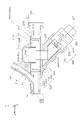
- FIG. 1 schematically shows the external configuration of the medical connector 10
- FIG. 2 shows its longitudinal section (YZ section).
- the medical connector 10 is a Y connector that is used by being connected to the guiding catheter GC via the rotator 20 .
- the side to which the guiding catheter GC is connected (positive Z-axis direction) is called the distal side
- the opposite side negative Z-axis direction
- the distal end is referred to as the “distal end”, the distal end and its vicinity as the “distal portion”, and the proximal end as the “basal end”.
- the end and the vicinity thereof are referred to as the "base end”.
- the Z-axis direction is also called the front-rear direction
- the Y-axis direction is also called the vertical direction
- the Y-axis positive direction is also called the upward direction
- the Y-axis negative direction is also called the downward direction
- the X-axis direction is also called the horizontal direction.
- the orientation of the medical connector 10 is not limited to this.
- the configuration of the side surfaces of some members may be omitted.
- the medical connector 10 has a tubular main pipe portion 11 extending in the front-rear direction, and a tubular branch pipe portion 12 branching from the vicinity of the distal end portion and obliquely extending upward toward the base end side.
- the main tube portion 11 is formed with a lumen 13 that extends in the front-rear direction and penetrates the main tube portion 11 . is introduced into the guiding catheter GC.
- the branch tube portion 12 is formed with a lumen 14 that communicates with the lumen 13 of the main tube portion 11 . Via 14 liquid agents, for example contrast media or saline, are supplied.
- the medical connector 10 includes a hemostasis valve opening/closing mechanism 100 and a long medical device fixing mechanism 200 .
- the opening/closing mechanism 100 is provided closer to the proximal side than the fixing mechanism 200 .
- the opening/closing mechanism 100 constitutes a portion of the base end side of the main pipe portion 11 of the medical connector 10
- the fixing mechanism 200 connects a portion of the distal end side of the main pipe portion 11 of the medical connector 10 and the branch pipe portion 12 .
- Configure The configurations of the opening/closing mechanism 100 and the fixing mechanism 200 will be described in order below.
- the medical connector 10 is held and used by an operator such as a doctor, for example.
- an operator holds the main tube portion 11 of the medical connector 10 in the posture shown in FIG.
- the medical connector 10 is grasped so as to be positioned near the operating member 280 .
- FIG. 3 shows its longitudinal section (YZ section), and FIGS. 4 and 5 show its perspective views.
- 3 and 4 show the opening/closing mechanism 100 with the hemostatic valve 120 closed (hereinafter referred to as "closed-state opening/closing mechanism 100c")
- FIG. 5 shows the hemostatic valve 120 in the opened state.
- the opening/closing mechanism 100 (hereinafter referred to as "open-state opening/closing mechanism 100o") is shown.
- the opening/closing mechanism 100 is a mechanism for opening/closing a hemostatic valve 120 that suppresses the outflow of blood through the lumen 13 of the main pipe portion 11 (FIG. 2) of the medical connector 10.
- the opening/closing mechanism 100 is a mechanism that switches the hemostatic valve 120 between a closed state and an open state each time the operating member 180 is pressed by the operator.
- the opening/closing mechanism 100 includes a housing 110 , a hemostatic valve 120 , a penetrating member 130 , an operating member 180 , a force transmission member 140 and a holding mechanism 160 .
- the housing 110 is a tubular member having a distal opening 112 and a proximal opening 111 and a lumen 113 communicating between the distal opening 112 and the proximal opening 111 .
- the lumen 113 is a through-hole extending in the front-rear direction (Z-axis direction) and constitutes part of the lumen 13 of the main tube portion 11 of the medical connector 10 .
- the housing 110 is made of resin, for example. As shown in FIG. 2, the proximal end of the fixing mechanism 200 is inserted and fixed in the lumen 113 .
- the Z-axis direction is an example of a first direction in the scope of claims.
- the housing 110 is composed of a distal housing portion 110D and a proximal housing portion 110P.
- Each of the distal housing portion 110D and the proximal housing portion 110P is a tubular member formed with a lumen extending in the front-rear direction.
- a substantially flat plate-like partition wall 114 that is substantially perpendicular to the front-rear direction is formed by the wall portion of the proximal end of the distal housing portion 110D.
- the partition 114 is formed with a through hole 114 ⁇ /b>A that penetrates the partition 114 in the front-rear direction and constitutes a part of the lumen 113 .
- the cross-sectional shape of 114 A of through-holes is substantially circular, for example. 4 and 5, illustration of the distal housing portion 110D is omitted.
- FIG. 6 is a cross-sectional perspective view showing the configuration of the base end side housing portion 110P that constitutes the housing 110 in the first embodiment.
- a guide groove 115 extending in the front-rear direction is formed in the inner side surface of the proximal housing portion 110P.
- a pair of guide grooves 115 are formed so as to face each other in the left-right direction (X-axis direction).
- a member accommodating space 116 that communicates with the lumen 113, extends obliquely downward to the proximal side, and opens onto the surface of the proximal housing portion 110P. is formed.
- the hemostatic valve 120 is a substantially disk-shaped member made of an elastic material such as silicone rubber.
- the hemostasis valve 120 is fixed inside the housing 110 at a position distal to the partition wall 114 .
- a slit 121 is formed at a substantially central position in the hemostasis valve 120 as viewed in the Z-axis direction (FIG. 4).
- Hemostasis valve 120 is normally in a closed state in which slit 121 is closed and the valve is closed (FIGS. 3 and 4).
- lumen 113 is closed by hemostasis valve 120 , and outflow of blood from hemostasis valve 120 to the proximal side through lumen 113 is suppressed.
- each piece divided by the slit 121 is elastically deformed so as to be displaced toward the distal side, forming a through hole 122 that penetrates the hemostatic valve 120 in the front-rear direction. It will be in the closed open state (Fig. 5).
- a through hole 122 formed in the hemostatic valve 120 in the open state communicates with the distal opening 112 via the lumen 113 . Therefore, when the hemostasis valve 120 is in the open state, the lumen 113 is not closed at the position of the hemostasis valve 120 and is in an open state.
- the hemostatic valve 120 elastically deforms and returns to the closed state.
- FIG. 7 is a perspective view showing the external configuration of the penetrating member 130 and the force transmission member 140 in the first embodiment.
- the penetrating member 130 is a member in which a through hole 132 extending in the front-rear direction is formed, and is made of resin, for example. More specifically, the penetrating member 130 includes a substantially cylindrical body portion 131 having a through hole 132 extending in the front-rear direction, and a substantially flat plate-like main body portion 131 that protrudes downward from the vicinity of the center in the front-rear direction and is substantially perpendicular to the front-rear direction. and a flange portion 133 .
- a pair of guide projections 134 projecting in the left-right direction are formed on the side surface of the flange portion 133, and a continuous guide projection 135 extending in the vertical direction is formed on the proximal surface of the flange portion 133. ing.
- the vertical direction is an example of a third direction in the scope of claims.
- the penetrating member 130 is accommodated in the housing 110 closer to the proximal side than the hemostatic valve 120 .
- a through hole 132 in the through member 130 communicates with the proximal opening 111 of the housing 110 . Also, through hole 132 and lumen 113 of housing 110 are coaxial with each other.
- a pair of guide projections 134 ( FIG. 7 ) formed on the flange portion 133 are fitted into a pair of guide grooves 115 ( FIG. 6 ) formed on the housing 110 .
- the penetrating member 130 is slidable in the front-rear direction using the guide groove 115 as a guide in a state in which the vertical and horizontal positions of the penetrating member 130 are determined with respect to the housing 110 .
- Penetrating member 130 is positioned such that body portion 131 thereof faces through hole 114A of partition wall 114 in the front-rear direction.
- the penetrating member 130 which is slidable in the front-rear direction, is inserted into the through hole 114A at the tip of the main body 131, and presses the hemostatic valve 120 to open the hemostatic valve 120. and a non-pressing position P1 in which the hemostatic valve 120 is closed without pressing the .
- the through hole 122 formed in the hemostatic valve 120 and the through hole 132 of the penetrating member 130 communicate with each other.
- Penetrating member 130 is movable to a position where flange portion 133 contacts partition wall 114 of housing 110 on the distal end side, and the proximal end of penetrating member 130 is located at the proximal end portion of housing 110 on the proximal end side. can be moved to a position where it abuts on a convex portion 119 (FIGS. 3 and 6) formed on the .
- the pressing position P2 of the penetrating member 130 is an example of the second position in the claims, and the non-pressing position P1 of the penetrating member 130 is an example of the first position in the claims.
- FIG. 8 is a perspective view showing the external configuration of the operation member 180 and the holding mechanism 160 in the first embodiment.
- the operation member 180 is a substantially cylindrical member extending in a direction (hereinafter referred to as "operation direction D2") non-parallel to the front-rear direction (Z-axis direction).
- operation direction D2 is a direction with an angle of 35 degrees or more and 55 degrees or less with the front-rear direction, for example, a direction with an angle of 45 degrees with the front-rear direction, i. This is the oblique direction of 45 degrees toward the proximal side.
- the operation member 180 is supported by an outer cylinder 150 of a holding mechanism 160, which will be described later, and is slidable along the operation direction D2. A portion of the base end side of the operation member 180 is exposed from the outer tube 150, and can be pressed by an operator such as a doctor.
- the operation member 180 is made of resin, for example.
- the operation direction D2 is an example of a second direction in the claims.
- the force transmission member 140 is a substantially polygonal member and is made of resin, for example.
- a distal end surface 143 of the force transmission member 140 has a planar shape substantially orthogonal to the front-rear direction, and is in contact with the proximal surface of the flange portion 133 of the penetrating member 130 .
- a guide groove 144 continuously extending in the vertical direction is formed in the tip surface 143 .
- a guide protrusion 135 of the penetrating member 130 is fitted in the guide groove 144 .
- a concave portion 145 capable of accommodating the base end portion of the body portion 131 of the penetrating member 130 is formed on the upper surface of the force transmission member 140 .
- a protruding portion 142 is formed on the surface of the force transmission member 140 on the lower base end side.
- the force transmission member 140 is housed in the member housing space 116 of the housing 110 so as to be positioned between the penetrating member 130 and the operation member 180, and is slidable along the operation direction D2.
- the force transmission member 140 can transmit to the penetrating member 130 a force that moves the operating member 180 toward the penetrating member 130 along the operating direction D2.
- the force transmission member 140 can slide relative to the penetration member 130 along the vertical direction while contacting the proximal surface of the flange portion 133 of the penetration member 130 . That is, as shown in FIGS. 3 and 4, when the penetrating member 130 is at the non-pressing position P1 in which the hemostatic valve 120 is not pressed, the force transmission member 140 is at the retracted position P3 retracted downward to the proximal side. . The force transmission member 140 does not press the penetrating member 130 when the force transmission member 140 is at the retracted position P3. When the penetrating member 130 is not pressed by the force transmission member 140, the penetrating member 130 is positioned at the non-pressing position P1.
- the retracted position P3 of the force transmission member 140 is an example of a third position in the claims.
- the holding mechanism 160 (FIG. 8) employs a so-called double knock mechanism, and each time the operation member 180 slides along the operation direction D2, the force transmission member 140 is held at the retracted position P3, or The state is switched to the state in which the force transmission member 140 is held at the forward position P4.
- the holding mechanism 160 has an outer cylinder 150 , a rotor 170 and a biasing member 162 . Note that, in the present embodiment, part of the operating member 180 also constitutes part of the holding mechanism 160 .
- FIG. 9 is a perspective view showing the external configuration of the outer cylinder 150 in the first embodiment.
- the outer cylinder 150 is a substantially cylindrical member and is made of resin, for example.
- the outer cylinder 150 is attached to the tip of the portion of the housing 110 where the member accommodating space 116 is formed, with the axial direction thereof aligned with the operation direction D2.
- a toothed outer cylinder end face cam 153 is formed on the inner peripheral surface of the outer cylinder 150 .
- the outer cylinder end surface cam 153 is a cam in which shallow groove portions 154 and deep groove portions 155 are alternately formed in the circumferential direction.
- the outer cylinder end face cam 153 is composed of four shallow groove portions 154 and four deep groove portions 155 .
- a tooth-shaped operating member end face cam 182 is formed on the end face of the substantially cylindrical operating member 180 on the upper tip side. Further, on the outer peripheral surface of the operation member 180, a plurality of (four) sliding contacts 181, which are substantially rectangular parallelepiped projections, are formed.
- the operating member 180 is inserted into the hollow portion of the outer cylinder 150 , and the sliding contacts 181 on the outer peripheral surface of the operating member 180 are fitted into the deep grooves 155 on the inner peripheral surface of the outer cylinder 150 .
- the operation member 180 is slidable relative to the outer cylinder 150 in the axial direction of the outer cylinder 150, that is, along the operation direction D2, while the rotation thereof is restricted.
- the rotor 170 is a substantially disk-shaped member and is made of resin, for example.
- a plurality of (four) protrusions 173 are formed on the outer peripheral surface of the rotor 170 . Teeth are formed on the surface on the lower base end side of each projection 173 of the rotor 170 .
- the pitch of the ridges of the operating member end cam 182 of the operating member 180 is shifted by about 1/2 from the pitch of the ridges of the outer cylinder end cam 153 of the outer cylinder 150 .
- Each projection 173 is structured so that it cannot mesh with both the operating member end face cam 182 and the outer cylinder end face cam 153 at the same time.
- a concave portion 174 is formed in the upper tip side surface of the rotor 170 .
- the biasing member 162 is a substantially cylindrical spring and is made of metal such as stainless steel.
- the biasing member 162 is arranged between the rotor 170 and the force transmission member 140 (FIG. 7), and biases the force transmission member 140 toward the outside of the housing 110 along the operation direction D2.
- One end of the biasing member 162 is inserted into the recess 174 of the rotor 170 , and the projection 142 of the force transmission member 140 is inserted into the hollow portion of the other end of the biasing member 162 .
- the rotor 170 In the rotor retracted state in which the protruding portions 173 of the rotor 170 are fitted into the deep groove portions 155 of the outer cylinder end surface cam 153 of the outer cylinder 150, the rotor 170 is retracted downward to the base end side using the deep groove portions 155 as guides. Located in Therefore, in the rotor retracted state, as shown in FIGS. 3 and 4, the force transmission member 140 is located at the retracted position P3 in which the force transmission member 140 is retracted toward the lower base end side, and as a result, the penetrating member 130 is located at the non-pressing position P1. do. The rotor retracted state is maintained as long as the operating member 180 does not slide.
- each convex portion 173 is fitted into the shallow groove portion 154 of the outer cylinder end surface cam 153 of the outer cylinder 150, not the deep groove portion 155. .
- the rotor 170 is held at a position advanced to the upper tip side compared to the rotor retreated state in which the deep grooves 155 are fitted. Therefore, in the rotor advance state, as shown in FIG. 5, the force transmission member 140 advances to the advance position P4, and as a result, the penetrating member 130 moves to the pressing position P2. As long as the operating member 180 does not slide, the rotor advance state is maintained.
- each convex portion 173 is fitted into the deep groove portion 155 of the outer cylinder end surface cam 153 instead of the shallow groove portion 154 .
- the holding mechanism 160 returns to the rotor retracted state, the force transmission member 140 retracts to the retracted position P3, and the penetrating member 130 moves to the non-pressing position P1. In this manner, the holding mechanism 160 changes the state of the force transmission member 140 to the retracted position P3 or the forward position P3 each time the operation member 180 slides along the operation direction D2. It switches to the state held at P4.
- FIGS. 3 and 4 Operation of the opening/closing mechanism 100: Next, the operation of the opening/closing mechanism 100 of the hemostatic valve 120 will be described.
- the holding mechanism 160 In the initial state, as shown in FIGS. 3 and 4, the holding mechanism 160 is in the rotor retracted state. In this state, the force transmission member 140 is located at the retracted position P3, and the penetrating member 130 is not pressed by the force transmission member 140 and is located at the non-pressing position P1. Therefore, the hemostasis valve 120 is closed, and the opening/closing mechanism 100 is a closed state opening/closing mechanism 100c.
- valve opening operation For example, an operation of pressing the operation member 180 toward the inside of the housing 110 (that is, obliquely upward) along the operation direction D2 with the thumb of the operator holding the medical connector 10 (hereinafter referred to as "valve opening operation"). ) is applied, the operating member 180 slides obliquely upward along the operating direction D2. Accordingly, the holding mechanism 160 switches from the rotor backward state to the rotor forward state. In this state, as shown in FIG. 5, the force transmission member 140 is positioned at the forward position P4, and the penetrating member 130 is pressed by the force transmission member 140 and positioned at the pressing position P2. As a result, the distal end portion of the main body portion 131 of the penetrating member 130 presses the hemostatic valve 120 to open the hemostatic valve 120, and the opening/closing mechanism 100 becomes the open state opening/closing mechanism 100o.
- opening/closing mechanism 100 when the opening/closing mechanism 100 is in the open state opening/closing mechanism 100o, for example, the operator's thumb moves toward the inside of the housing 110 along the operation direction D2 with respect to the operation member 180 in the same manner as the valve opening operation.
- a pressing operation ie, obliquely upward
- valve closing operation a pressing operation
- the operating member 180 slides obliquely upward along the operation direction D2.
- the holding mechanism 160 switches from the rotor advance state to the rotor retreat state. In this state, as shown in FIGS.
- the force transmission member 140 is positioned at the retracted position P3, and the penetrating member 130 is not pressed by the force transmission member 140 and returns to the non-pressing position P1.
- the penetrating member 130 closes the hemostatic valve 120 without pressing the hemostatic valve 120, and the opening/closing mechanism 100 becomes the closed state opening/closing mechanism 100c.
- the holding mechanism 160 holds the force transmission member 140 at the retracted position P3, or the force transmission member 140 is held at the retracted position P3 every time the operation member 180 slides along the operation direction D2. 140 is held at the forward position P4.
- the holding mechanism 160 switches to the state where the force transmission member 140 is held at the forward position P4, the penetrating member 130 moves from the non-pressing position P1 to the pressing position P2, and the hemostatic valve 120 switches from the closed state to the open state.
- the holding mechanism 160 holds the force transmission member 140 at the advanced position P4, so that the hemostatic valve 120 is kept open.
- the holding mechanism 160 switches to the state in which the force transmission member 140 is held at the retracted position P3 as the operation member 180 slides again, the penetrating member 130 moves from the pressing position P2 to the non-pressing position P1, and the hemostatic valve is closed. 120 switches from open to closed. At this time, the holding mechanism 160 holds the force transmission member 140 at the retracted position P3, so that the hemostatic valve 120 is kept closed.
- the operation member 180 is slidable along the operation direction D2 that is non-parallel to the extending direction (Z-axis direction) of the lumen 113 of the housing 110.
- the opening/closing operation of the hemostatic valve 120 This is an operation of pressing the operating member 180 in the operating direction D2 that is non-parallel to the extending direction of the lumen 113 . Therefore, according to the opening/closing mechanism 100, the operator can easily open/close the hemostatic valve 120 with the thumb while holding the medical connector 10, and the operability of the opening/closing mechanism 100 can be improved. .
- the holding mechanism 160 has a cylindrical biasing member 162 that biases the force transmission member 140 toward the outside of the housing 110 along the operation direction D2, and faces the biasing member 162 of the force transmission member 140.
- a convex portion 142 is formed on the surface to be inserted into the hollow portion of the biasing member 162 . Therefore, according to the opening/closing mechanism 100, the force transmission member 140 and the biasing member 162 can be positioned easily and accurately, and the biasing force of the biasing member 162 can be effectively transferred to the force transmission member 140. , and the accuracy of the operation of the opening/closing mechanism 100 can be improved.
- the angle formed by the extension direction (Z-axis direction) of the lumen 113 of the housing 110 and the operation direction D2 of the operation member 180 is 35 degrees or more and 55 degrees or less. Therefore, according to the opening/closing mechanism 100, the operating member 180 can be very easily operated by the operator's thumb while holding the medical connector 10, thereby effectively improving the operability of the opening/closing mechanism 100. be able to.
- the penetrating member 130 has a main body portion 131 in which a through hole 132 is formed, and a flange portion 133 projecting vertically from the main body portion 131 . It is configured to be slidable relative to the penetrating member 130 along the vertical direction while abutting on the side surface. Therefore, according to the opening/closing mechanism 100, the force transmission member 140 slides along the operation direction D2 that is non-parallel to the extending direction (Z-axis direction) of the lumen 113 of the housing 110, and the penetrating member 130 slides along the extending direction. (Z-axis direction) sliding can be efficiently converted, and the operability of the opening/closing mechanism 100 can be effectively improved.
- FIG. 10 is an explanatory diagram showing the configuration of a modification (opening/closing mechanism 100X) of the opening/closing mechanism 100 of the first embodiment.
- the opening/closing mechanism 100X differs from the opening/closing mechanism 100 in that the operation member 180 and the force transmission member 140 are integral members.
- a connecting shaft 147 extends from the lower proximal side surface of the force transmission member 140 toward the lower proximal side, and the connecting shaft 147 passes through a through hole 179 formed in the rotor 170 to operate. It extends to the member 180 and is connected to the operating member 180 .
- the operation member 180 and the force transmission member 140 are integrated and slide along the operation direction D2.
- the biasing member 162 is arranged substantially parallel to the front-rear direction between the front end side surface of the lower portion of the flange portion 133 of the penetrating member 130 and the housing 110 .
- the biasing member 162 indirectly biases the force transmission member 140 toward the outside of the housing 110 along the operation direction D2 by biasing the penetrating member 130 toward the base end side.
- the holding mechanism 160 holds the force transmission member 140 at the retracted position P3, or holds the force transmission member 140 at the retracted position P3. , the state where the member 140 is held at the forward position P4. Therefore, the operability of the opening/closing mechanism 100X can be similarly improved by the opening/closing mechanism 100X.
- FIG. 11 and 12 are explanatory diagrams showing the configuration. 11 and 12 show the structure of the longitudinal section (YZ section). 11 shows the fixing mechanism 200 (hereinafter referred to as “released state fixing mechanism 200n”) in which the fixation of the long medical device such as the guide wire GW is released, and FIG.
- the fixing mechanism 200 (hereinafter referred to as “fixed state fixing mechanism 200f”) is shown in a state where the scale-shaped medical device is fixed.
- the fixing mechanism 200 is a mechanism for fixing and releasing the fixation of the elongated medical device inserted through the lumen 13 of the main tube portion 11 (FIG. 2) of the medical connector 10 . Each time the operating member 280 is pressed by the operator, the fixing mechanism 200 is in a fixed state in which the elongated medical device is fixed, or in an unfixed state in which the fixed lengthy medical device is released. It is a mechanism that switches to The fixing mechanism 200 includes a housing 210 , a tubular body 290 , a pressing member 240 , an operating member 280 , a force transmission member 230 and a holding mechanism 260 .
- the housing 210 is a tubular member having a distal opening 212 and a proximal opening 211 and a lumen 213 communicating between the distal opening 212 and the proximal opening 211 .
- the lumen 213 is a through hole extending in the front-rear direction (Z-axis direction) and constitutes a part of the lumen 13 of the medical connector 10 .
- the housing 210 is made of resin, for example.
- a branch pipe portion 12 is formed at the distal end portion of the housing 210 .
- the proximal end of the housing 210 is inserted into and fixed to the lumen 113 at the distal end of the housing 110 of the opening/closing mechanism 100 .
- the proximal end portion of the housing 210 restricts movement of the hemostatic valve 120 toward the distal side.
- a cylindrical body accommodation space 215 which is a portion of the lumen 213 whose diameter is enlarged.
- a retraction space 214 is formed above the cylindrical body housing space 215 and communicates with the vicinity of the center in the front-rear direction.
- a member accommodation space 216 is formed that communicates with the vicinity of the center in the front-rear direction, extends obliquely toward the lower base end side, and opens onto the surface of the housing 210. As shown in FIG.
- FIG. 13 is a cross-sectional perspective view showing the configuration of the circular tubular body 290, the pressing member 240 and the force transmission member 230 in the first embodiment.
- the tubular body 290 is a flexible tubular member having a through hole 291 into which an elongated medical device such as a guide wire GW is inserted.
- the tubular body 290 is made of an elastic material such as silicone rubber.
- the tubular body 290 is mounted in the tubular body housing space 215 in such a posture that its axis is parallel to the front-rear direction (Z-axis direction).
- the through hole 291 communicates with the distal opening 212 and the proximal opening 211 of the housing 210 .
- the through hole 291 and the lumen 213 of the housing 210 are coaxial with each other.
- the front-rear direction (Z-axis direction) is an example of a fifth direction in the scope of claims.
- each stopper 220 includes a main body portion 221 having approximately the same diameter as the circular tubular body 290, a first small diameter portion 223 positioned on the circular tubular body 290 side with respect to the main body portion 221 and having a diameter smaller than that of the main body portion 221, and a main body portion 221.
- a second small-diameter portion 222 having a diameter smaller than that of the main body portion 221 is located on the opposite side of the circular tubular body 290 .
- the first small diameter portion 223 of each stopper 220 is inserted into the through hole 291 of the tubular body 290 .
- each stopper 220 is formed with a concave portion 224 into which a convex portion (not shown) of the housing 210 is fitted.
- Each stopper 220 is positioned in the longitudinal direction with respect to the housing 210 by fitting the convex portion and the concave portion 224 , and as a result, the cylindrical body 290 is positioned in the longitudinal direction with respect to the housing 210 .
- the pressing member 240 is a member in which a through hole 241 extending in the front-rear direction is formed, and is made of resin, for example.
- the pressing member 240 has a substantially rectangular parallelepiped shape, and the length (dimension in the front-rear direction) of the portion above the center position of the through hole 241 is longer than the other portions.
- the inner diameter of the through hole 241 of the pressing member 240 is substantially the same as the outer diameter of the tubular body 290 , and the tubular body 290 is inserted into the through hole 241 .
- the lower surface 244 of the pressing member 240 is a substantially flat surface that is substantially perpendicular to the vertical direction, and has a guide convex portion 245 that continuously extends in the front-rear direction.
- the pressing member 240 is housed across the evacuation space 214 , the cylindrical body housing space 215 and the member housing space 216 of the housing 210 .
- the pressing member 240 is slidable along the vertical direction (Y-axis direction), which is a direction orthogonal to the axial direction (Z-axis direction) of the tubular body 290 .
- the vertically slidable pressing member 240 has a non-pressing position P5 where the through hole 241 of the pressing member 240 is coaxial with the through hole 291 of the cylindrical body 290 as shown in FIG. and a pressing position P6 displaced upward from the non-pressing position P5.
- the pressing member 240 is positioned at the non-pressing position P5 (FIG.
- the pressing member 240 does not substantially press the cylindrical body 290.
- the state in which the pressing member 240 is not substantially pressed means a state in which the inner peripheral surface of the through hole 241 of the pressing member 240 and the outer peripheral surface of the tubular body 290 are separated from each other, and the through hole 241 of the pressing member 240 is not pressed. Since the inner diameter is the same as or slightly smaller than the outer shape of the cylindrical body 290 before being inserted into the through hole 241, the inner peripheral surface of the through hole 241 of the pressing member 240 and the outer peripheral surface of the cylindrical body 290 are in close contact. including the state of being The vertical direction (Y-axis direction) is an example of a sixth direction in the claims, and the non-pressing position P5 is an example of a fifth position in the claims.
- the pressing member 240 presses a portion of the cylindrical body 290 excluding both end portions (in this embodiment, the center portion in the front-rear direction) upward from the outer peripheral side. to elastically deform the circular tubular body 290 .
- the inner peripheral surface of the elastically deformed cylindrical body 290 (mainly the contact point CP1, which is the lower portion of the inner peripheral surface of the deformed portion of the cylindrical body 290) is pressed against the elongated medical device.
- the retraction space 214 of the housing 210 has a sufficient size for the pressing member 240 to deform the cylindrical body 290 to the extent that the long medical device can be fixed.
- the pressed position P6 is an example of a sixth position in the claims.
- the operation member 280 is a substantially cylindrical member that extends in a direction (hereinafter referred to as "operation direction D7") that is not parallel to the front-rear direction (Z-axis direction).
- the operation direction D7 is a direction with an angle of 35 degrees or more and 55 degrees or less with the front-rear direction. 45-degree oblique direction toward the side).
- the operation member 280 is supported by an outer cylinder 250 of a holding mechanism 260, which will be described later, and is slidable along the operation direction D7. A portion of the base end side of the operation member 280 is exposed from the outer tube 250, and can be pressed by an operator such as a doctor.
- the operation member 280 is made of resin, for example.
- the operation direction D7 is an example of a seventh direction in the claims.
- the force transmission member 230 is a substantially polygonal member and is made of resin, for example.
- An upper surface 234 of the force transmission member 230 is a substantially flat surface that is substantially orthogonal to the vertical direction, and has a guide groove 235 that continuously extends in the front-rear direction.
- a guide protrusion 245 of the pressing member 240 is fitted in the guide groove 235 .
- a protruding portion 232 is formed on a surface 233 on the lower base end side of the force transmission member 230 .
- force transmission member 230 is housed within member housing space 216 of housing 210 so as to be positioned between pressing member 240 and operation member 280, and is positioned in operation direction D7. It is slidable along.
- the force transmission member 230 can transmit to the pressing member 240 a force that moves the operating member 280 closer to the pressing member 240 along the operation direction D7.
- the force transmission member 230 Since the force transmission member 230 is configured as described above, it can slide relative to the pressing member 240 in the front-rear direction (Z-axis direction) while contacting the lower surface 244 of the pressing member 240 . That is, as shown in FIG. 11, when the pressing member 240 is at the non-pressing position P5 where it does not press the cylindrical body 290, the force transmission member 230 is at the retracted position P7 retracted toward the lower proximal side. The force transmission member 230 does not press the pressing member 240 when the force transmission member 230 is at the retracted position P7. When the pressing member 240 is not pressed by the force transmission member 230, the elastic restoring force of the cylindrical body 290 positions the pressing member 240 at the non-pressing position P5.
- the retracted position P7 is an example of a seventh position in the claims.
- the force transmission member 230 slides obliquely upward along the operation direction D7 from the retracted position P7 and moves from the retracted position P7 to the advanced position P8 closer to the cylindrical body 290, , the force transmission member 230 slides toward the distal end side relative to the pressure member 240 while maintaining the state in which the guide protrusion 245 of the pressure member 240 is fitted in the guide groove 235 of the force transmission member 230. .
- the force transmission member 230 presses the pressing member 240 to position the pressing member 240 at the pressing position P6.
- the forward position P8 is an example of an eighth position in the claims.
- the holding mechanism 260 employs a so-called double knock mechanism. is held at the forward position P8.
- the holding mechanism 260 has an outer cylinder 250 , a rotor 270 and a biasing member 262 . Note that, in the present embodiment, part of the operating member 280 also constitutes part of the holding mechanism 260 . Since the configuration of the holding mechanism 260 is the same as the configuration of the holding mechanism 160 of the opening/closing mechanism 100 described above, description thereof will be omitted.
- the holding mechanism 260 is in the rotor retracted state.
- the force transmission member 230 is located at the retracted position P7, and the pressing member 240 is not pressed by the force transmission member 230 and is located at the non-pressing position P5.
- the elongated medical device such as the guide wire GW inserted through the lumen 213 of the housing 210 (the lumen 13 of the main tube portion 11) is not fixed. That is, the fixing mechanism 200 is a released state fixing mechanism 200n.
- fixing operation when an operation of pressing the operation member 280 obliquely upward along the operation direction D7 (hereinafter referred to as “fixing operation”) is applied by the thumb of the operator holding the medical connector 10, the operation member 280 is operated. It slides obliquely upward along the direction D7. Accordingly, the holding mechanism 260 switches from the rotor backward state to the rotor forward state. In this state, as shown in FIG. 12, the force transmission member 230 is positioned at the forward position P8, and the pressing member 240 is pressed by the force transmission member 230 and positioned at the pressing position P6.
- the circular tubular body 290 is pressed by the pressing member 240 and elastically deformed to fix the long medical device inserted through the lumen 213 of the housing 210 .
- the fixing mechanism 200 becomes a fixed state fixing mechanism 200f.
- the fixing mechanism 200 when the fixing mechanism 200 is in the fixed state fixing mechanism 200f, for example, an operator's thumb can press the operation member 280 obliquely upward along the operation direction D7 in the same manner as the fixing operation ( hereinafter referred to as "unlocking operation"), the operating member 280 slides obliquely upward along the operating direction D7.
- the holding mechanism 260 switches from the rotor advance state to the rotor retreat state. In this state, as shown in FIG. 11, the force transmission member 230 is positioned at the retracted position P7, and the pressing member 240 is not pressed by the force transmission member 230 and moved to the non-pressing position P5 by the elastic restoring force of the cylindrical body 290. return.
- the circular tubular body 290 is not pressed by the pressing member 240 and is not elastically deformed, so that the long medical device inserted through the lumen 213 of the housing 210 is released from fixation. As a result, the fixing mechanism 200 returns to the released state fixing mechanism 200n.
- the fixing mechanism 200 switches to the released state fixing mechanism 200n or the fixed state fixing mechanism 200f each time the operation member 280 is pressed (fixing operation and unlocking operation).
- the operation member 280 is slidable along the operation direction D7 that is non-parallel to the direction parallel to the axis of the cylindrical body 290 (the Z-axis direction). Therefore, the fixing operation and the fixing release operation of the long medical device are operations of pressing the operating member 280 in the operating direction D7 that is not parallel to the direction parallel to the axis of the circular tubular body 290 . Therefore, according to the fixing mechanism 200 of the present embodiment, the operator can fix and fix the long medical device by pressing the operation member 280 with the thumb while holding the medical connector 10 . The release can be realized, and the fixation condition of the elongated medical device can be grasped by touch and sight, so that the operability of the fixation mechanism 200 can be improved.
- the holding mechanism 260 has a cylindrical biasing member 262 that biases the force transmission member 230 toward the pressing member 240 .
- a protrusion 232 to be inserted is formed. Therefore, according to the fixing mechanism 200 of the present embodiment, the force transmission member 230 and the biasing member 262 can be positioned easily and accurately, and the biasing force of the biasing member 262 can be effectively applied. The force can be transmitted to the force transmission member 230, and the precision of the operation of the fixing mechanism 200 can be improved.
- the angle between the direction parallel to the axis of the circular tubular body 290 (the Z-axis direction) and the operating direction D7 of the operating member 280 is 35 degrees or more and 55 degrees or less. Therefore, according to the fixation mechanism 200 of the present embodiment, the operator can very easily operate the operation member 280 with the thumb while holding the medical connector 10, and the operability of the fixation mechanism 200 is improved. can be substantially improved.
- the force transmission member 230 is configured to be slidable relative to the pressing member 240 along the direction (Z-axis direction) parallel to the axis of the cylindrical body 290 while contacting the surface of the pressing member 240 .
- sliding of the force transmission member 230 along the operation direction D7 and sliding of the pressing member 240 along the vertical direction can be efficiently converted. , the operability of the fixing mechanism 200 can be effectively improved.
- FIG. 14 is an explanatory diagram showing the external configuration of the medical connector 10A according to the second embodiment.
- the same configurations as those of the medical connector 10 of the first embodiment described above are denoted by the same reference numerals, and descriptions thereof will be omitted as appropriate.
- the medical connector 10A includes an opening/closing mechanism 300 and a fixing mechanism 200.
- the configuration of the fixing mechanism 200 included in the medical connector 10A is the same as the configuration of the fixing mechanism 200 included in the medical connector 10 of the first embodiment. Therefore, below, the opening-and-closing mechanism 300 with which 10 A of medical connectors of 2nd Embodiment are provided is demonstrated.
- FIG. 15 to 17 are explanatory diagrams showing the configuration of the opening/closing mechanism 300.
- FIG. FIG. 15 shows the configuration of a longitudinal section (YZ section) of the opening/closing mechanism 300
- FIGS. 15 and 16 show the opening/closing mechanism 300 with the hemostatic valve 320 closed (hereinafter referred to as "closed-state opening/closing mechanism 300c")
- FIG. 17 shows the hemostatic valve 320 opened.
- the opening/closing mechanism 300 in the open state hereinafter referred to as "open opening/closing mechanism 300o" is shown.
- the opening/closing mechanism 300 is a mechanism for opening/closing a hemostatic valve 320 that suppresses the outflow of blood through the lumen 13 of the main pipe portion 11 (FIG. 14) of the medical connector 10A.
- the opening/closing mechanism 300 of the present embodiment is a mechanism that switches between the closed state of the hemostatic valve 320 and the opened state of the hemostatic valve 320 each time the operating member 380 is pressed by the operator. be.
- the opening/closing mechanism 300 includes a housing 310 , a hemostatic valve 320 , a penetrating member 330 , an operating member 380 , a force transmission member 340 and a holding mechanism 360 .
- FIG. 18 is a cross-sectional perspective view showing the configuration of the housing 310 in the second embodiment.
- the housing 310 is a tubular member having a distal opening 312 and a proximal opening 311 and a lumen 313 communicating between the distal opening 312 and the proximal opening 311 .
- a lumen 313 formed in the housing 310 is a through-hole extending in the front-rear direction (Z-axis direction) and forms part of the lumen 13 of the main tube portion 11 of the medical connector 10A.
- the housing 310 is made of resin, for example.
- the Z-axis direction is an example of a first direction in the scope of claims.
- a substantially flat plate-like partition wall 314 that is substantially perpendicular to the front-rear direction is formed inside the housing 310 near the center in the front-rear direction.
- the partition 314 is formed with a through hole 314 ⁇ /b>A that penetrates the partition 314 in the front-rear direction and constitutes a part of the lumen 313 .
- the cross-sectional shape of 314 A of through-holes is substantially circular, for example.
- a vertically extending member accommodating space 316 is formed inside the housing 310 on the base end side of the partition wall 314 .
- the member accommodation space 316 opens to the surface of the housing 110 at the top of the housing 110 .
- the hemostasis valve 320 is a member having the same configuration as the hemostasis valve 120 of the first embodiment.
- the hemostasis valve 320 is fixed inside the housing 310 at a position distal to the partition wall 314 .
- Hemostasis valve 320 is normally in a closed state in which slit 321 is closed and the valve is closed (FIGS. 15 and 16).
- the hemostatic valve 320 is in an open state in which a through hole 322 is formed to penetrate the hemostatic valve 320 in the front-rear direction (FIG. 17).
- a substantially annular boss 328 is arranged between the hemostatic valve 320 and the partition wall 314 of the housing 310 .
- FIG. 19 is a perspective view showing the external configuration of the penetrating member 330 and the force transmission member 340 in the second embodiment.
- the penetrating member 330 is a tubular member having a through hole 332 extending in the front-rear direction, and is made of resin, for example.
- a protrusion 335 is formed on the outer peripheral surface of the penetrating member 330 so as to protrude in the left-right direction (X-axis direction) perpendicular to both the front-rear direction and the up-down direction.
- Two protrusions 335 are provided, one on each side of the penetrating member 330 . In this embodiment, the positions of the two protrusions 335 are the same as viewed in the X-axis direction.
- the horizontal direction is an example of a fourth direction in the scope of claims.
- the penetrating member 330 is housed inside the housing 310 on the proximal side of the hemostatic valve 320 .
- the through hole 332 communicates with the proximal opening 311 of the housing 310 .
- the through hole 332 of the penetrating member 330 and the lumen 313 of the housing 310 are coaxial with each other.
- the penetrating member 330 housed in the housing 310 is slidable in the front-rear direction while being positioned vertically and horizontally with respect to the housing 310 .
- Penetrating member 330 is positioned to face through hole 314A of partition wall 314 in the front-rear direction.
- the penetrating member 330 which is slidable in the front-rear direction, has its distal end inserted into the through hole 314A, and presses the hemostatic valve 320 to open the hemostatic valve 320 (state shown in FIG. 17). , a non-pressing position P1 (the state shown in FIGS. 15 and 16) in which the hemostatic valve 320 is not pressed and the hemostatic valve 320 is closed. As shown in FIG.
- the through hole 322 formed in the hemostatic valve 320 and the through hole 332 of the penetrating member 330 communicate with each other.
- the pressing position P2 of the penetrating member 330 is an example of the second position in the claims, and the non-pressing position P1 of the penetrating member 330 is an example of the first position in the claims.
- the operating member 380 is a substantially cylindrical member extending in a direction (hereinafter referred to as "operating direction D2") non-parallel to the front-rear direction (Z-axis direction).
- the operation member 380 is supported by an outer cylinder 350 of a holding mechanism 360, which will be described later, and is slidable along the operation direction D2.
- the operating direction D2 is a vertical direction that forms an angle of approximately 90 degrees with the front-rear direction. In this specification, approximately 90 degrees means a range of about 90 degrees plus or minus 5 degrees.
- a portion of the base end side of the operation member 380 is exposed from the outer tube 350 and can be pressed by an operator such as a doctor.
- the operating member 380 is made of resin, for example.
- the operation direction D2 is an example of a second direction in the claims.
- the force transmission member 340 is a substantially rectangular parallelepiped member, and is made of resin, for example.
- a through hole 344 extending in the front-rear direction is formed in the force transmission member 340 , and the through member 330 is inserted through the through hole 344 .
- Communication grooves 345 are formed in the left and right side surfaces of the force transmission member 340 to communicate the outer peripheral surface of the force transmission member 340 and the through holes 344 .
- Each communication groove 345 extends in a direction orthogonal to the left-right direction and non-parallel to both the front-rear direction and the up-down direction. More specifically, each communication groove 345 extends in a direction from the lower proximal side toward the upper distal side.
- each communication groove 345 with respect to the front-rear direction is, for example, 45 degrees.
- Each projection 335 of the penetrating member 330 is slidably inserted into each communication groove 345 . This allows the penetrating member 330 to slide relative to the force transmitting member 340 along the extending direction of the communication groove 345 .
- a projecting portion 343 protruding upward is formed on the upper surface of the force transmission member 340 .
- a projecting portion 342 projecting downward is formed on the lower surface of the force transmission member 340 .
- the force transmission member 340 is slidably accommodated in the member accommodation space 316 of the housing 310 along the operation direction D2.
- a biasing member 362 is arranged below the force transmission member 340 in the housing 310, and the biasing member 362 biases the force transmission member 340 upward.
- One end of the biasing member 362 is fixed to the bottom surface of the member accommodation space 316 of the housing 310, and the convex portion 342 (FIG. 19) of the force transmission member 340 is provided in the hollow portion of the other end of the biasing member 362. is inserted.
- the force transmission member 340 can transmit to the penetrating member 330 a force that moves the operating member 380 toward the penetrating member 330 along the operating direction D2. That is, as shown in FIGS. 15 and 16, when the force transmission member 340 is positioned at the retracted position P3 in which the force transmission member 340 is retracted upward, the protrusion 335 of the penetrating member 330 is positioned at the lower base end side of the communication groove 345 of the force transmission member 340. (hereinafter referred to as “closed position portion 345A”), whereby the penetrating member 330 is located at the proximal side position, that is, the non-pressing position P1 where the hemostatic valve 120 is not pressed.
- the retracted position P3 of the force transmission member 340 is an example of a third position in the claims.
- the force transmission member 340 receives the pressing force from the operation member 380 and moves downward along the operation direction D2 from the retracted position P3 to the forward position P4, the penetrating member 330
- the convex portion 335 relatively moves in the communication groove 345 of the force transmission member 340 to the upper tip side and reaches the upper tip portion (hereinafter referred to as “open position portion 345B”), thereby pressing the penetrating member 330. It moves to the position on the distal side, that is, the pressing position P2 where the hemostasis valve 120 is pressed to open.
- the forward position P4 of the force transmission member 340 is an example of a fourth position in the claims.
- the holding mechanism 360 (FIG. 15) is a so-called double-knock mechanism, and each time the operation member 380 slides along the operation direction D2, the force transmission member 340 is held at the retracted position P3, or the force transmission member 340 is held at the forward position P4.
- the holding mechanism 360 has an outer cylinder 350 and a rotor 370 .
- part of the operation member 380 and the biasing member 362 also constitute part of the holding mechanism 360 .
- the configuration of the holding mechanism 360 is the same as the configuration of the holding mechanism 160 of the opening/closing mechanism 100 of the first embodiment described above, so description thereof will be omitted. That is, in the description of the configuration of the holding mechanism 160 of the opening/closing mechanism 100 described above, if the outer cylinder 150 is replaced with the outer cylinder 350, the rotor 170 is replaced with the rotor 370, and the biasing member 162 is replaced with the biasing member 362, good.
- the biasing member 362 is arranged between the housing 310 and the force transmission member 340 as described above, rather than between the force transmission member 340 and the rotor 370 . The biasing member 362 biases the force transmission member 340 toward the outside of the housing 310 along the operation direction D2 even in such an arrangement.
- valve opening operation For example, an operation of pressing the operation member 380 toward the inside of the housing 310 (ie, downward) along the operation direction D2 with the index finger of the operator holding the medical connector 10A (hereinafter referred to as "valve opening operation"). is applied, the operating member 380 slides downward along the operating direction D2. Accordingly, the holding mechanism 360 switches from the rotor backward state to the rotor forward state. In this state, as shown in FIG. 17, the force transmission member 340 is displaced to the forward position P4, and the penetrating member 330 is pressed toward the distal end side by the force transmission member 340 and is displaced to the pressing position P2. As a result, the distal end of the penetrating member 330 presses the hemostatic valve 320 to open the hemostatic valve 320, and the opening/closing mechanism 300 becomes an open opening/closing mechanism 300o.
- the operation member 380 when the opening/closing mechanism 300 is in the open state opening/closing mechanism 300o, the operation member 380 is pressed toward the inside of the housing 310 (that is, downward) along the operation direction D2 in the same manner as the valve opening operation.
- valve closing operation When an operation (hereinafter referred to as "valve closing operation") is applied, the operation member 380 slides downward along the operation direction D2.
- the holding mechanism 360 switches from the rotor advance state to the rotor retreat state.
- the force transmission member 340 is displaced to the retracted position P3, and the penetrating member 330 returns to the non-pressing position P1 without being pushed toward the distal end side by the force transmission member 340. .
- the penetrating member 330 closes the hemostatic valve 320 without pressing the hemostatic valve 320, and the opening/closing mechanism 300 becomes the closed opening/closing mechanism 300c.
- the opening/closing mechanism 300 switches to the closed state opening/closing mechanism 300c or the open state opening/closing mechanism 300o each time the operation member 380 is pressed (valve opening operation and valve closing operation).
- the opening/closing mechanism 300 of the second embodiment has the same configuration as that of the first embodiment. Opening and closing operation can be easily performed, and the operability of the opening and closing mechanism 300 can be improved.
- the holding mechanism 360 has a cylindrical biasing member 362 that biases the force transmission member 340 toward the operating member 380.
- the surface facing the biasing member 362 has a hollow portion of the biasing member 362.
- a protrusion 342 to be inserted is formed. Therefore, according to the opening/closing mechanism 300 of the second embodiment, similarly to the opening/closing mechanism 100 of the first embodiment, positioning between the force transmission member 340 and the biasing member 362 can be performed easily and accurately.
- the biasing force of the biasing member 362 can be effectively transmitted to the force transmission member 340, and the accuracy of the operation of the opening/closing mechanism 300 can be improved.
- the angle formed by the extension direction (Z-axis direction) of the lumen 313 of the housing 310 and the operation direction D2 of the operation member 380 is approximately 90 degrees. Therefore, according to the opening/closing mechanism 300 of the second embodiment, the operator can very easily open/close the hemostatic valve 320 with the thumb or forefinger while holding the medical connector 10A. Operability can be effectively improved.
- the penetrating member 330 has a protrusion 335 that protrudes in the left-right direction, which is a direction perpendicular to both the extending direction (Z-axis direction) of the lumen 313 of the housing 310 and the operation direction D2.
- a communication groove 345 into which the projection 335 is inserted is formed.
- the communication groove 345 extends in a direction orthogonal to the left-right direction and non-parallel to both the extension direction (Z-axis direction) of the lumen 313 of the housing 310 and the operation direction D2.
- the sliding of the force transmission member 340 along the vertical direction substantially orthogonal to the extending direction of the lumen 313 of the housing 310 and the sliding of the penetrating member 330 in the extending direction are performed.
- the motion can be efficiently converted, and the operability of the opening/closing mechanism 300 can be effectively improved.
- FIG. 20 is an explanatory diagram showing a modified example (opening/closing mechanism 300X) configuration of the opening/closing mechanism 300 of the second embodiment.
- the opening/closing mechanism 300X of the modified example shown in FIG. 20 differs from the opening/closing mechanism 300 of the second embodiment described above in that the operation member 380 and the force transmission member 340 are integrated.
- a connecting shaft 347 extends upward from the upper surface of the force transmission member 340 . is connected with Therefore, in the opening/closing mechanism 300X of the modified example, the operation member 380 and the force transmission member 340 are integrally slid along the operation direction D2.
- the holding mechanism 360 holds the force transmission member 340 at the retracted position P3 or the forward position P4. , and switches to . Therefore, the operability of the opening/closing mechanism 300 can be similarly improved by the opening/closing mechanism 300X of the modified example.
- FIG. 21 is an explanatory diagram showing the structure of a longitudinal section (YZ section) of the medical connector 10B according to the third embodiment.
- the same configurations as those of the medical connector 10 of the first embodiment described above are denoted by the same reference numerals, and the description thereof will be omitted as appropriate.
- the medical connector 10B includes an opening/closing mechanism 100 and a fixing mechanism 200B.
- the opening/closing mechanism 100 provided in the medical connector 10B is the same as the opening/closing mechanism 100 provided in the medical connector 10 of the first embodiment, so description thereof will be omitted. do.
- FIG. 22 and 23 are explanatory diagrams showing the configuration of the fixing mechanism 200B, showing the configuration of its longitudinal section (YZ section).
- FIG. 22 shows the fixing mechanism 200B (released state fixing mechanism 200n) in which the fixation of the long medical device such as the guide wire GW is released
- FIG. 2 shows the fixing mechanism 200B in a closed state (fixed state fixing mechanism 200f). A side view of some members is shown.
- a fixing mechanism 200B of the third embodiment includes a circular tubular body 490 instead of the circular tubular body 290 in the fixing mechanism 200 of the first embodiment.
- the tubular body 490 differs from the tubular body 290 in the configuration of the through holes 491 . That is, the inner diameter of the through-hole 491 extending through the circular tubular body 490 in the longitudinal direction changes according to the position along the axial direction. More specifically, in the circular tubular body 490, the inner diameter d1a of the through hole 491 at the central portion 490a is smaller than the inner diameter d1b at the distal end portion 490b and smaller than the inner diameter d1c at the proximal end portion 490c.
- the through hole 491 is wider at the distal end and the proximal end than at the central portion. Therefore, the area S1a of the through-hole 491 in the cross section of the fixing mechanism 200B is equal to the area S1a of the through-hole 491 in the cross section of the central portion 490a (more specifically, the cross section of the fixing mechanism 200B (the same applies hereinafter)). It is smaller than the area S1b of the portion 490b and smaller than the area S1c of the base end portion 490c.
- the cross-sectional shape of the through-hole 491 at each position may take any shape, but is circular, for example.
- the through hole 491 is an example of a first through hole in the claims.
- Stoppers 420 are attached to the distal end and the proximal end of the tubular body 490 in the same manner as in the first embodiment.
- Each stopper 420 has a main body portion 421 having substantially the same outer diameter as the central portion 490 a of the circular tubular body 490 , and a second body portion 421 located on the circular tubular body 490 side with respect to the main body portion 421 and having a smaller outer diameter than the main body portion 421 .
- 1 small-diameter portion 423 and a second small-diameter portion 422 located on the opposite side of the main body portion 421 from the cylindrical body 490 and having an outer diameter smaller than that of the main body portion 421 .
- the first small diameter portion 423 is inserted into the through hole 491 .
- the main body portion 421 is formed with a concave portion 424 into which a convex portion (not shown) of the housing 210 is fitted.
- the stopper 420 is positioned in the front-rear direction with respect to the housing 210 by fitting the projection and the recess 424 , and as a result, the cylindrical body 490 is positioned in the front-rear direction with respect to the housing 210 .
- distal stop 420 connects distal end 490 b to housing 210 and proximal stop 420 connects proximal end 490 c to housing 210 .
- a through hole 425 communicating with the through hole 491 is formed in each stopper 420 .
- the shape of the through-hole 425 in the cross section at each portion may take any shape, but is circular, for example.
- the tip-side stopper 420 is an example of the tip-side connecting portion in the claims, and the through hole 425 of the tip-side stopper 420 is an example of the second through hole in the claims.
- the proximal-side stopper 420 is an example of a proximal-side connecting portion in the claims, and the through-hole 425 of the proximal-side stopper 420 is an example of a third through-hole in the claims. .
- the inner diameter d2 of the through hole 425 is larger than the inner diameter d1a of the through hole 491 in the central portion 490a. Therefore, the area S2 of the through hole 425 in the cross section of the first small diameter portion 423 of the stopper 420 on the distal end side is larger than the area S1a of the through hole 491 in the cross section of the central portion 490a of the cylindrical body 490 .
- the inner diameter d3 of the through-hole 425 in the first small-diameter portion 423 (the portion inserted into the through-hole 491 of the circular tubular body 490) of the stopper 420 on the proximal side is It is larger than the inner diameter d1a of the hole 491. Therefore, the area S3 of the through hole 425 in the cross section of the first small diameter portion 423 of the stopper 420 on the proximal end side is larger than the area S1a of the through hole 491 in the cross section of the central portion 490a of the tubular body 490 .
- the outer diameter at the central portion 490a is larger than the outer diameter at the distal end portion 490b and larger than the outer diameter at the proximal end portion 490c. Therefore, in the cylindrical body 490 housed in the substantially hollow columnar cylindrical body housing space 215 in the housing 210, the outer peripheral surface of the central portion 490a is in contact with or close to the inner peripheral surface of the cylindrical body housing space 215. On the other hand, the outer peripheral surfaces of the distal end portion 490 b and the proximal end portion 490 c are separated from the inner peripheral surface of the cylindrical body accommodating space 215 .
- a fixing mechanism 200B of the third embodiment includes a pressing member 440 instead of the pressing member 240 of the first embodiment.
- the pressing member 440 has a shape obtained by removing the portion above the through hole 241 of the pressing member 240 of the first embodiment. That is, the pressing member 440 is arranged below the central portion 490a of the tubular body 490, and in the released state described above, the upper surface of the pressing member 440 is in contact with or close to the outer peripheral surface of the central portion 490a of the tubular body 490.
- the pressing member 440 is slidable along the vertical direction (Y-axis direction) perpendicular to the axial direction (Z-axis direction) of the tubular body 490 .
- the vertically slidable pressing member 440 has a non-pressing position P5 at which it does not substantially press the cylindrical body 490 as shown in FIG. 22, and an upward displacement from the non-pressing position P5 as shown in FIG. and the pressing position P6.
- the state in which the pressing member 440 is not substantially pressed means that the upper surface of the pressing member 440 is in close contact with the outer peripheral surface of the tubular member 490 in addition to the state in which the upper surface of the pressing member 440 is separated from the outer peripheral surface of the tubular member 490. including the state of
- the pressing member 440 presses the central portion 490a of the cylindrical body 490 upward from the outer peripheral side to elastically deform the central portion 490a.
- the contact point CP1 which is the lower portion of the inner peripheral surface of the central portion 490a, which is the inner peripheral surface of the through hole 491 of the central portion 490a that is elastically deformed, and the upper portion of the inner peripheral surface of the central portion 490a.
- the contact points CP3 and are pressed against the elongated medical device, and the elongated medical device is clamped by the two contact points CP1 and CP3, thereby being fixed to the fixing mechanism 200B and restricted from sliding in the front-rear direction. be.
- the area S2 of the through hole 425 in the cross section of the first small diameter portion 423 of the stopper 420 on the distal side and the through hole in the cross section of the first small diameter portion 423 of the stopper 420 on the proximal side The area S3 of 425 is larger than the area S1a of the through hole 491 in the cross section of the central portion 490a of the circular tubular body 490 . Therefore, even when the pressing member 440 presses the central portion 490a of the circular tubular body 490 and the elongated medical device is fixed, the elongated medical device may not be pressed against the inner peripheral surface of the stopper 420.
- the configurations of the medical connector 10, the opening/closing mechanisms 100 and 300, and the fixing mechanism 200 in the above embodiment are merely examples, and various modifications are possible.
- the surface of the force transmission member 140 facing the biasing member 162 is formed with the protrusion 142 that is inserted into the hollow portion of the biasing member 162 . It does not have to be formed.
- the convex portion 232 of the force transmission member 230 and the convex portion 342 of the force transmission member 340 can be omitted.
- a so-called double knock mechanism is used as the holding mechanism 260 that switches between the state in which the force transmission member 230 is held in the retracted position P7 and the state in which the force transmission member 230 is held in the forward position P8.
- Other mechanisms such as a heart cam mechanism may be used as the holding mechanism 260 .
- holding mechanism 160 and/or holding mechanism 360 other mechanisms such as a heart cam mechanism may be used instead of the double knock mechanism.
- the housing 210 and the stoppers 220, 240 may be integral members.
- the medical connector 10 includes both the opening/closing mechanism 100 (or the opening/closing mechanism 300) and the fixing mechanism 200. and only one of
Abstract
Through the present invention, operability of an opening/closing mechanism is enhanced. The opening/closing mechanism comprises a housing, a hemostasis valve, a through-member, an operating member, a force transmission mechanism, and a holding mechanism. The through-member can be positioned in a first position for placing the hemostasis valve in a closed state, and a second position for pressing on the hemostasis valve to place the hemostasis valve in an open state, along a first direction in which a lumen of the housing extends. The operating member is capable of sliding along a second direction not parallel to the first direction. The force transmission member is disposed so as to be able to slide between the through-member and the operating member in the second direction, and can be positioned in a third position for placing the through-member in the first position, and a fourth position for pressing on the through-member to place the through-member in the second position. Each time that the operating member slides along the second direction, the holding mechanism is switched to a state in which the force transmission member is held in the third position or a state in which the force transmission member is held in the fourth position.
Description
本明細書に開示される技術は、止血弁の開閉機構、長尺状医療機器の固定機構および医療用コネクタに関する。
The technology disclosed in this specification relates to a hemostatic valve opening/closing mechanism, a fixing mechanism for a long medical device, and a medical connector.
Yコネクタは、ガイディングカテーテルに接続されて使用される医療用コネクタである。Yコネクタは、主管部と、主管部から分岐した分岐管部とを有しており、主管部を介して例えばガイドワイヤやカテーテル等の長尺状医療機器がガイディングカテーテル内に導入され、分岐管部を介して例えば造影剤や生理食塩水等の液剤が供給される。Yコネクタには、主管部の管腔を介した血液の流出を抑制する止血弁を開閉するための開閉機構と、長尺状医療機器を固定するための固定機構とが設けられている。
A Y connector is a medical connector that is used by being connected to a guiding catheter. The Y connector has a main tube and a branch tube branched from the main tube. An elongated medical device such as a guide wire or a catheter is introduced into the guiding catheter through the main tube and branched. Liquid agents such as a contrast medium and physiological saline are supplied through the tube. The Y connector is provided with an opening/closing mechanism for opening and closing a hemostatic valve that suppresses the outflow of blood through the lumen of the main tube, and a fixing mechanism for fixing the long medical device.
従来のYコネクタにおける止血弁の開閉機構では、主管部の管腔と同軸の貫通孔が形成された貫通部材(オープナー)が設けられており、貫通部材に対して、主管部の管腔の軸線方向に平行な方向に押圧する操作を行うことにより、貫通部材が止血弁を押圧して止血弁が開放された開状態と、貫通部材が止血弁から離隔して止血弁が閉鎖された閉状態とを切り替える(例えば、特許文献1参照)。また、従来のYコネクタにおける長尺状医療機器の固定機構では、長尺状医療機器が挿通される貫通孔が形成された弾性の固定弁が設けられており、スクリュを回転操作して軸線方向に移動させ、これに伴いプッシャを軸線方向に移動させることにより、固定弁がプッシャに押圧されて弾性変形し、固定弁の貫通孔の内径が縮小して長尺状医療機器が固定された固定状態と、固定弁がプッシャに押圧されず、固定弁の貫通孔の内径が拡大して長尺状医療機器の固定が解除された固定解除状態とを切り替える(例えば、特許文献1参照)。
In the opening and closing mechanism of the hemostatic valve in the conventional Y connector, a penetrating member (opener) having a through hole coaxial with the lumen of the main pipe is provided. By performing a pressing operation in a direction parallel to the direction, an open state in which the hemostatic valve is opened by the penetrating member pressing the hemostatic valve, and a closed state in which the hemostatic valve is closed by the penetrating member being separated from the hemostatic valve. (See Patent Document 1, for example). In addition, in the fixing mechanism of the long medical device in the conventional Y connector, an elastic fixing valve having a through hole through which the long medical device is inserted is provided. by moving the pusher in the axial direction along with this, the fixed valve is pressed by the pusher and elastically deformed, and the inner diameter of the through hole of the fixed valve is reduced to fix the long medical device. and a release state in which the fixation valve is not pressed by the pusher and the inner diameter of the through hole of the fixation valve is expanded to release the fixation of the elongated medical device (see, for example, Patent Document 1).
上述した従来のYコネクタの構成では、止血弁の開閉操作が、貫通部材を主管部の管腔の軸線方向に押圧する操作であるため、操作が行いにくいという課題がある。また、上述した従来のYコネクタの構成では、長尺状医療機器の固定/固定解除操作が、スクリュを回転させる操作であるため、操作が煩雑である上に、長尺状医療機器の固定具合を触感や視覚的に捉えることができないという課題がある。
In the configuration of the conventional Y connector described above, the operation of opening and closing the hemostatic valve is an operation of pressing the penetrating member in the axial direction of the lumen of the main tube, so there is a problem that the operation is difficult. In addition, in the configuration of the conventional Y connector described above, fixing/unfixing the elongated medical device is an operation of rotating the screw. There is a problem that it is not possible to grasp the tactile sense or visually.
本明細書では、上述した課題を解決することが可能な技術を開示する。
This specification discloses a technology capable of solving the above-described problems.
本明細書に開示される技術は、例えば、以下の形態として実現することが可能である。
The technology disclosed in this specification can be implemented, for example, in the following forms.
(1)本明細書に開示される止血弁の開閉機構は、ハウジングと、止血弁と、貫通部材と、操作部材と、力伝達部材と、保持機構とを備える。ハウジングは、先端側開口と基端側開口とに連通する管腔が形成された管状の部材である。止血弁は、ハウジング内に取り付けられており、通常時は閉状態にあり、基端側から押圧されると前記ハウジングの前記先端側開口に連通する貫通孔が形成された開状態となる。貫通部材は、止血弁より基端側において前記管腔の延伸方向である第1の方向に沿って摺動可能に前記ハウジング内に収容されている。貫通部材には、前記ハウジングの前記基端側開口に連通する貫通孔が形成されている。貫通部材は、前記止血弁を前記閉状態とする第1の位置と、前記第1の位置よりも前記第1の方向に沿って先端側の位置で且つ、前記止血弁を押圧することによって前記止血弁を前記開状態にして前記止血弁の前記貫通孔と前記貫通部材の前記貫通孔とを連通させる第2の位置と、に位置し得る。操作部材は、前記第1の方向とは非平行な第2の方向に沿って摺動可能な部材である。力伝達部材は、前記貫通部材と前記操作部材との間に前記第2の方向に摺動可能に配置され、前記第2の方向に沿って前記操作部材が前記貫通部材に近づくように移動する力を前記貫通部材に伝達する部材である。力伝達部材は、前記貫通部材を前記第1の位置に位置させる第3の位置と、前記貫通部材を押圧して前記第2の位置に位置させる第4の位置と、に位置し得る。保持機構は、前記操作部材が前記第2の方向に沿って摺動する毎に、前記力伝達部材を前記第3の位置に保持した状態、あるいは、前記力伝達部材を前記第4の位置に保持した状態、に切り替わる機構である。
(1) A hemostatic valve opening/closing mechanism disclosed in the present specification includes a housing, a hemostatic valve, a penetrating member, an operation member, a force transmission member, and a holding mechanism. The housing is a tubular member having a lumen that communicates with the distal opening and the proximal opening. The hemostatic valve is mounted in the housing and is normally in a closed state, and when pressed from the proximal end side, it is in an open state in which a through hole communicating with the distal end side opening of the housing is formed. The penetrating member is housed in the housing slidably along the first direction, which is the extending direction of the lumen, on the proximal side of the hemostatic valve. A through hole is formed in the through member to communicate with the base end side opening of the housing. The penetrating member has a first position in which the hemostasis valve is closed, and a position on the distal side of the first position along the first direction, and presses the hemostasis valve to close the hemostasis valve. a second position in which the hemostasis valve is in the open state and the through hole of the hemostasis valve and the through hole of the penetrating member are communicated with each other; The operating member is a member that can slide along a second direction that is non-parallel to the first direction. A force transmission member is disposed between the penetrating member and the operating member so as to be slidable in the second direction, and the operating member moves along the second direction so as to approach the penetrating member. A member for transmitting force to the penetrating member. The force transmission member can be positioned in a third position that positions the penetrating member in the first position and in a fourth position that presses the penetrating member to position the penetrating member in the second position. The holding mechanism holds the force transmission member at the third position or holds the force transmission member at the fourth position each time the operation member slides in the second direction. It is a mechanism that switches to the held state.
このように、本開閉機構では、操作部材が第2の方向に沿って摺動する毎に、保持機構が、力伝達部材を第3の位置に保持した状態、あるいは、力伝達部材を第4の位置に保持した状態、に切り替わる。操作部材の摺動に伴い保持機構が力伝達部材を第4の位置に保持した状態に切り替わると、貫通部材が第1の位置から第2の位置に移動し、止血弁が閉状態から開状態に切り替わる。このとき、保持機構が力伝達部材を第4の位置に保持することにより、止血弁の開状態が維持される。また、再度の操作部材の摺動に伴い保持機構が力伝達部材を第3の位置に保持した状態に切り替わると、貫通部材が第2の位置から第1の位置に移動し、止血弁が開状態から閉状態に切り替わる。このとき、保持機構が力伝達部材を第3の位置に保持することにより、止血弁の閉状態が維持される。また、本開閉機構では、操作部材が、ハウジングの管腔の延伸方向とは非平行な第2の方向に沿って摺動可能であるため、止血弁の開閉操作が、操作部材をハウジングの管腔の延伸方向とは非平行な第2の方向に押圧する操作となる。そのため、本開閉機構によれば、手技者が本開閉機構を備えるデバイスを把持した状態で、親指または人差し指により止血弁の開閉操作を容易に行うことができ、開閉機構の操作性を向上させることができる。
Thus, in this opening/closing mechanism, each time the operation member slides along the second direction, the holding mechanism holds the force transmission member at the third position or holds the force transmission member at the fourth position. , and then switch to . When the holding mechanism switches to the state of holding the force transmission member at the fourth position as the operation member slides, the penetrating member moves from the first position to the second position, and the hemostasis valve changes from the closed state to the open state. switch to At this time, the holding mechanism holds the force transmission member at the fourth position, thereby maintaining the open state of the hemostatic valve. Further, when the holding mechanism switches to the state in which the force transmission member is held at the third position as the operating member slides again, the penetrating member moves from the second position to the first position, opening the hemostasis valve. state to the closed state. At this time, the holding mechanism holds the force transmission member at the third position, thereby maintaining the closed state of the hemostatic valve. In addition, in the present opening/closing mechanism, the operating member is slidable along the second direction non-parallel to the extending direction of the lumen of the housing. This is an operation of pressing in a second direction that is non-parallel to the extending direction of the cavity. Therefore, according to the present opening/closing mechanism, the operator can easily perform the opening/closing operation of the hemostatic valve with the thumb or forefinger while holding the device provided with the present opening/closing mechanism, thereby improving the operability of the opening/closing mechanism. can be done.
(2)上記止血弁の開閉機構において、前記操作部材と前記力伝達部材とは一体部材である構成としてもよい。本止血弁の開閉機構によれば、部品点数を削減することができる。
(2) In the opening/closing mechanism of the hemostatic valve, the operation member and the force transmission member may be configured as an integral member. According to this hemostatic valve opening/closing mechanism, the number of parts can be reduced.
(3)上記止血弁の開閉機構において、前記保持機構は、直接または他の部材を介して、前記力伝達部材を前記第2の方向に沿って前記ハウジングの外部側に向けて付勢する筒状の付勢部材を有し、前記力伝達部材または前記他の部材における前記付勢部材に対向する表面には、前記付勢部材の中空部に挿入される凸部が形成されている構成としてもよい。本止血弁の開閉機構によれば、力伝達部材と付勢部材との間の位置決めを容易にかつ精度良く行うことができると共に、付勢部材の付勢力を効果的に力伝達部材に伝達することができ、開閉機構の動作の精度を向上させることができる。
(3) In the hemostatic valve opening/closing mechanism, the holding mechanism is a cylinder that urges the force transmission member in the second direction toward the outside of the housing, either directly or via another member. and a convex portion inserted into the hollow portion of the biasing member is formed on the surface of the force transmission member or the other member facing the biasing member. good too. According to the opening/closing mechanism of the hemostasis valve, positioning between the force transmission member and the biasing member can be performed easily and accurately, and the biasing force of the biasing member can be effectively transmitted to the force transmission member. It is possible to improve the accuracy of the operation of the opening/closing mechanism.
(4)上記止血弁の開閉機構において、前記第1の方向と前記第2の方向とのなす角は、35度以上、55度以下である構成としてもよい。本止血弁の開閉機構によれば、手技者が本開閉機構を備えるデバイスを把持した状態で、親指により止血弁の開閉操作を極めて容易に行うことができ、開閉機構の操作性を効果的に向上させることができる。
(4) In the opening/closing mechanism of the hemostatic valve, the angle between the first direction and the second direction may be 35 degrees or more and 55 degrees or less. According to the opening and closing mechanism of the hemostatic valve, the operator can easily open and close the hemostatic valve with the thumb while holding the device equipped with the opening and closing mechanism. can be improved.
(5)上記止血弁の開閉機構において、前記貫通部材は、前記貫通孔が形成された本体部と、前記本体部から前記第1の方向に直交する第3の方向に突出するフランジ部と、を有し、前記力伝達部材は、前記フランジ部における基端側の表面に当接しつつ、前記第3の方向に沿って前記貫通部材に対して相対的にスライド移動可能に構成されている構成としてもよい。本止血弁の開閉機構によれば、ハウジングの管腔の延伸方向とは非平行な第2の方向に沿った力伝達部材の摺動と、貫通部材の該延伸方向の摺動とを、効率的に変換することができ、開閉機構の操作性を効果的に向上させることができる。
(5) In the opening/closing mechanism of the hemostatic valve, the penetrating member includes a body portion having the through hole formed therein, a flange portion projecting from the body portion in a third direction perpendicular to the first direction, wherein the force transmission member is configured to be slidable relative to the penetrating member along the third direction while abutting on the proximal surface of the flange portion may be According to this hemostasis valve opening/closing mechanism, the sliding of the force transmission member along the second direction non-parallel to the extending direction of the lumen of the housing and the sliding of the penetrating member in the extending direction can be efficiently performed. can be effectively converted, and the operability of the opening/closing mechanism can be effectively improved.
(6)上記止血弁の開閉機構において、前記第1の方向と前記第2の方向とのなす角は、略90度である構成としてもよい。本止血弁の開閉機構によれば、手技者が本開閉機構を備えるデバイスを把持した状態で、親指または人差し指により止血弁の開閉操作を極めて容易に行うことができ、開閉機構の操作性を効果的に向上させることができる。
(6) In the opening/closing mechanism of the hemostasis valve, the angle between the first direction and the second direction may be approximately 90 degrees. According to this hemostatic valve opening/closing mechanism, an operator can very easily open/close the hemostatic valve with a thumb or forefinger while holding the device equipped with this opening/closing mechanism. can be substantially improved.
(7)上記止血弁の開閉機構において、前記力伝達部材は、前記第2の方向に摺動可能であり、前記貫通部材は、前記第1の方向と前記第2の方向との両方に直交する第4の方向に突出する凸部を有し、前記力伝達部材には、前記凸部が挿入される溝であって、前記第4の方向に直交し、かつ、前記第1の方向と前記第2の方向との両方に非平行な方向に伸びる溝が形成されている構成としてもよい。本止血弁の開閉機構によれば、ハウジングの管腔の延伸方向に略直交する第2の方向に沿った力伝達部材の摺動と、貫通部材の該延伸方向の摺動とを、効率的に変換することができ、開閉機構の操作性を効果的に向上させることができる。
(7) In the hemostatic valve opening/closing mechanism, the force transmission member is slidable in the second direction, and the penetrating member is perpendicular to both the first direction and the second direction. and the force transmission member has a groove into which the protrusion is inserted, the groove being perpendicular to the fourth direction and the first direction. A configuration may be employed in which grooves extending in non-parallel directions are formed in both of the second directions. According to the opening and closing mechanism of the hemostasis valve, the sliding of the force transmission member along the second direction substantially orthogonal to the extending direction of the lumen of the housing and the sliding of the penetrating member in the extending direction can be efficiently performed. , and the operability of the opening/closing mechanism can be effectively improved.
(8)本明細書に開示される長尺状医療機器の固定機構は、ハウジングと、円管状体と、押圧部材と、操作部材と、力伝達部材と、保持機構とを備える。ハウジングは、先端側開口と基端側開口とに連通する管腔が形成された管状の部材である。円管状体は、前記ハウジング内に取り付けられ、前記長尺状医療機器が挿入される貫通孔が形成された可撓性の部材である。円管状体の貫通孔は、前記ハウジングの前記先端側開口および前記基端側開口に連通している。押圧部材は、前記円管状体の軸線に平行な第5の方向に直交する第6の方向に沿って摺動可能に前記ハウジング内に収容されている。押圧部材は、第5の位置と、前記第5の位置から前記第6の方向に沿って変位した第6の位置であって、前記円管状体の両端部を除く一部分を外周側から押圧して変形させる第6の位置と、に位置し得る。操作部材は、前記第5の方向とは非平行な第7の方向に沿って摺動可能な部材である。力伝達部材は、前記押圧部材と前記操作部材との間に前記第7の方向に摺動可能に配置され、前記第7の方向に沿って前記操作部材が前記押圧部材に近づくように移動する力を前記押圧部材に伝達する部材である。力伝達部材は、前記押圧部材を前記第5の位置に位置させる第7の位置と、前記押圧部材を押圧して前記第6の位置に位置させる第8の位置と、に位置し得る。保持機構260は、前記操作部材が前記第7の方向に沿って摺動する毎に、前記力伝達部材を前記第7の位置に保持した状態、あるいは、前記力伝達部材を前記第8の位置に保持した状態、に切り替わる。本長尺状医療機器の固定機構は、前記押圧部材が前記第6の位置に位置するときに、変形した前記円管状体の内周面が前記長尺状医療機器に押しつけられることによって前記長尺状医療機器が前記円管状体に固定されるように構成されている。
(8) A fixing mechanism for a long medical device disclosed in this specification includes a housing, a tubular body, a pressing member, an operation member, a force transmission member, and a holding mechanism. The housing is a tubular member having a lumen that communicates with the distal opening and the proximal opening. A circular tubular body is a flexible member that is attached within the housing and has a through hole formed therein, into which the elongated medical device is inserted. The through-hole of the tubular body communicates with the distal side opening and the proximal side opening of the housing. The pressing member is housed in the housing slidably along a sixth direction orthogonal to a fifth direction parallel to the axis of the tubular body. The pressing member is at a fifth position and a sixth position displaced from the fifth position along the sixth direction, and presses a portion of the cylindrical body excluding both end portions from the outer peripheral side. and a sixth position that deforms the The operation member is a member slidable along a seventh direction non-parallel to the fifth direction. The force transmission member is disposed between the pressing member and the operation member so as to be slidable in the seventh direction, and moves along the seventh direction so that the operation member approaches the pressing member. It is a member that transmits force to the pressing member. The force transmission member can be positioned at a seventh position that positions the pressing member at the fifth position, and an eighth position that presses the pressing member to position the pressing member at the sixth position. The holding mechanism 260 holds the force transmission member at the seventh position or holds the force transmission member at the eighth position each time the operation member slides along the seventh direction. , and switches to . The fixation mechanism for the elongated medical device is configured such that when the pressing member is positioned at the sixth position, the deformed inner peripheral surface of the circular tubular body is pressed against the elongated medical device, thereby fixing the length of the elongated medical device. A scale-shaped medical device is configured to be fixed to the circular tubular body.
このように、本長尺状医療機器の固定機構では、操作部材が第7の方向に沿って摺動する毎に、保持機構が、力伝達部材を第7の位置に保持した状態、あるいは、力伝達部材を第8の位置に保持した状態、に切り替わる。操作部材の摺動に伴い保持機構が力伝達部材を第8の位置に保持した状態に切り替わると、押圧部材が第5の位置から第6の位置に移動し、円管状体が弾性変形して長尺状医療機器が円管状体に固定される。このとき、保持機構が力伝達部材を第8の位置に保持することにより、長尺状医療機器が固定された状態が維持される。また、再度の操作部材の摺動に伴い保持機構が力伝達部材を第7の位置に保持した状態に切り替わると、押圧部材が第6の位置から第5の位置に移動し、円管状体の形状が復元して長尺状医療機器の固定が解除される。このとき、保持機構が力伝達部材を第7の位置に保持することにより、長尺状医療機器の固定が解除された状態が維持される。また、本長尺状医療機器の固定機構では、操作部材が、円管状体の軸線に平行な方向とは非平行な第7の方向に沿って摺動可能であるため、長尺状医療機器の固定操作および固定解除操作が、操作部材を円管状体の軸線に平行な方向とは非平行な第7の方向に押圧する操作となる。そのため、本長尺状医療機器の固定機構によれば、手技者が本固定機構を備えるデバイスを把持した状態で、親指により操作部材を押圧するという操作しやすい操作で、長尺状医療機器の固定および固定解除を実現することができると共に、長尺状医療機器の固定具合を触感や視覚により把握することができるため、固定機構の操作性を向上させることができる。
Thus, in the fixing mechanism of the elongated medical device, the holding mechanism holds the force transmission member at the seventh position each time the operation member slides along the seventh direction, or the state in which the force transmission member is held at the eighth position. When the holding mechanism switches to the state where the force transmission member is held at the eighth position as the operation member slides, the pressing member moves from the fifth position to the sixth position, elastically deforming the cylindrical body. An elongated medical device is secured to the tubular body. At this time, the holding mechanism holds the force transmission member at the eighth position, thereby maintaining the fixed state of the long medical device. Further, when the holding mechanism switches to the state in which the force transmission member is held at the seventh position as the operation member slides again, the pressing member moves from the sixth position to the fifth position, and the cylindrical body is moved. The shape is restored and the fixation of the elongated medical device is released. At this time, the holding mechanism holds the force transmission member at the seventh position, so that the elongated medical device is kept unlocked. In addition, in the fixation mechanism for the elongated medical device, the operating member can slide along the seventh direction that is non-parallel to the direction parallel to the axis of the tubular body. The fixing operation and the fixing release operation are operations for pressing the operating member in a seventh direction non-parallel to the direction parallel to the axis of the tubular body. Therefore, according to the fixation mechanism of the long medical device, the operator can easily operate the operation member by pressing the operation member with the thumb while holding the device including the fixation mechanism. Since it is possible to realize fixation and release of the fixation, and the degree of fixation of the long medical device can be grasped by touch and sight, the operability of the fixation mechanism can be improved.
(9)上記長尺状医療機器の固定機構において、前記保持機構は、前記力伝達部材を前記押圧部材に近付く方向に付勢する筒状の付勢部材を有し、前記力伝達部材における前記付勢部材に対向する表面には、前記付勢部材の中空部に挿入される凸部が形成されている構成としてもよい。本長尺状医療機器の固定機構によれば、力伝達部材と付勢部材との間の位置決めを容易にかつ精度良く行うことができると共に、付勢部材の付勢力を効果的に力伝達部材に伝達することができ、固定機構の動作の精度を向上させることができる。
(9) In the fixing mechanism for a long medical device, the holding mechanism has a tubular biasing member that biases the force transmission member in a direction toward the pressing member, and the The surface facing the biasing member may be formed with a convex portion that is inserted into the hollow portion of the biasing member. According to the fixing mechanism of the elongated medical device, the positioning between the force transmission member and the biasing member can be performed easily and accurately, and the biasing force of the biasing member can be effectively applied to the force transmission member. can be transmitted to, and the accuracy of the operation of the fixing mechanism can be improved.
(10)上記長尺状医療機器の固定機構において、前記第5の方向と前記第7の方向とのなす角は、35度以上、55度以下である構成としてもよい。本長尺状医療機器の固定機構によれば、本固定機構を備えるデバイスを把持した状態で、親指により操作部材の操作を極めて容易に行うことができ、固定機構の操作性を効果的に向上させることができる。
(10) In the fixing mechanism for a long medical device, the fifth direction and the seventh direction may form an angle of 35 degrees or more and 55 degrees or less. According to the fixation mechanism of the long medical device, it is possible to operate the operation member very easily with the thumb while holding the device equipped with the fixation mechanism, effectively improving the operability of the fixation mechanism. can be made
(11)上記長尺状医療機器の固定機構において、前記力伝達部材は、前記押圧部材の表面に当接しつつ、前記第5の方向に沿って前記押圧部材に対して相対的にスライド移動可能に構成されている構成としてもよい。本長尺状医療機器の固定機構によれば、第7の方向に沿った力伝達部材の摺動と、第7の方向に沿った押圧部材の摺動とを、効率的に変換することができ、固定機構の操作性を効果的に向上させることができる。
(11) In the fixing mechanism for a long medical device, the force transmission member is slidable relative to the pressing member along the fifth direction while being in contact with the surface of the pressing member. It is good also as the structure comprised in. According to the fixing mechanism of the elongated medical device, it is possible to efficiently convert the sliding of the force transmission member along the seventh direction and the sliding of the pressing member along the seventh direction. It is possible to effectively improve the operability of the fixing mechanism.
(12)本明細書に開示される他の長尺状医療機器の固定機構は、ハウジングと、円管状体と、先端側接続部と、基端側接続部と、押圧部材とを備える。ハウジングは、先端側開口と基端側開口とに連通する管腔が形成され、前記管腔に前記長尺状医療機器を収容可能な管状の部材である。円管状体は、前記ハウジング内に取り付けられ、前記長尺状医療機器が挿入される第1貫通孔が形成された可撓性の円管状体であって、前記第1貫通孔は、前記ハウジングの前記先端側開口および前記基端側開口に連通している。先端側接続部は、前記円管状体の先端部を前記ハウジングに接続すると共に、前記円管状体の前記第1貫通孔に連通する第2貫通孔が形成されている。基端側接続部は、前記円管状体の基端部を前記ハウジングに接続すると共に、前記円管状体の前記第1貫通孔に連通する第3貫通孔が形成されている。押圧部材は、前記円管状体の軸線に非平行な方向から、前記円管状体の両端部を除く押圧部位を押圧するように構成され、かつ、前記ハウジング内に収容されている。前記先端側接続部の前記固定機構の横断面における前記第2貫通孔の面積、および、前記基端側接続部の前記横断面における前記第3貫通孔の面積は、前記押圧部位の前記横断面における前記第1貫通孔の面積よりも大きい。
(12) Another fixing mechanism for an elongated medical device disclosed in this specification includes a housing, a tubular body, a distal connecting portion, a proximal connecting portion, and a pressing member. The housing is a tubular member having a lumen that communicates with the distal opening and the proximal opening, and that can accommodate the elongated medical device in the lumen. The circular tubular body is a flexible circular tubular body mounted in the housing and having a first through hole into which the elongated medical device is inserted, wherein the first through hole is located in the housing. communicates with the distal side opening and the proximal side opening of the. The distal end connecting portion connects the distal end portion of the cylindrical body to the housing, and is formed with a second through hole that communicates with the first through hole of the cylindrical body. The proximal end connecting portion connects the proximal end portion of the tubular body to the housing, and has a third through hole communicating with the first through hole of the tubular body. The pressing member is configured to press a pressing portion excluding both ends of the tubular body from a direction non-parallel to the axis of the tubular body, and is accommodated in the housing. The area of the second through-hole in the cross-section of the fixing mechanism of the distal end-side connecting portion and the area of the third through-hole in the cross-section of the proximal-side connecting portion are the same as the cross-section of the pressing portion. is larger than the area of the first through hole in .
このように、本長尺状医療機器の固定機構では、押圧部材が円管状体の両端部を除く押圧部位を押圧すると、円管状体が弾性変形して長尺状医療機器が円管状体に固定される。このとき、先端側接続部の第2貫通孔の面積、および、基端側接続部の第3貫通孔の面積は、円管状体の押圧部位における第1貫通孔の面積よりも大きいため、押圧部材が円管状体の押圧部位を押圧することにより長尺状医療機器が固定されている状態においても、長尺状医療機器が先端側接続部および基端側接続部の内周面に押しつけられることが抑制され、長尺状医療機器の損傷をより効果的に抑制することができる。
As described above, in the fixation mechanism for the elongated medical device, when the pressing member presses the pressing portion excluding both end portions of the tubular body, the tubular body is elastically deformed and the elongated medical device becomes the tubular body. Fixed. At this time, since the area of the second through-hole of the distal-side connecting portion and the area of the third through-hole of the proximal-side connecting portion are larger than the area of the first through-hole in the pressing portion of the cylindrical body, Even in a state where the long medical device is fixed by the member pressing the pressing portion of the tubular body, the long medical device is pressed against the inner peripheral surfaces of the distal end side connecting portion and the proximal end side connecting portion. is suppressed, and damage to the long medical device can be suppressed more effectively.
なお、本明細書に開示される技術は、種々の形態で実現することが可能であり、例えば、止血弁の開閉機構、長尺状医療機器の固定機構、止血弁の開閉機構および/または長尺状医療機器の固定機構を備える医療用コネクタ、医療用コネクタを備える医療機器等の形態で実現することができる。
The technology disclosed in the present specification can be implemented in various forms. It can be realized in the form of a medical connector provided with a fixing mechanism for a scale-shaped medical device, a medical device provided with a medical connector, and the like.
A.第1実施形態:
A-1.医療用コネクタの構成:
図1および図2は、第1実施形態における医療用コネクタの構成を示す説明図である。図1には、医療用コネクタ10の外観構成を概略的に示し、図2には、その縦断面(YZ断面)を示している。医療用コネクタ10は、ローテータ20を介してガイディングカテーテルGCに接続されて使用されるYコネクタである。本明細書では、医療用コネクタ10において、ガイディングカテーテルGCが接続される側(Z軸正方向側)を先端側といい、その反対側(Z軸負方向側)を基端側という。また、医療用コネクタ10およびその各構成部材について、先端側の端を「先端」といい、先端およびその近傍を「先端部」といい、基端側の端を「基端」といい、基端およびその近傍を「基端部」という。また、説明の便宜上、Z軸方向を前後方向ともいい、Y軸方向を上下方向ともいい、Y軸正方向を上方向ともいい、Y軸負方向を下方向ともいい、X軸方向を左右方向ともいう。ただし、医療用コネクタ10の姿勢はこれに限られない。また、以降の断面図において、一部の部材については側面の構成を省略している場合がある。 A. First embodiment:
A-1. Configuration of medical connectors:
1 and 2 are explanatory diagrams showing the configuration of the medical connector according to the first embodiment. FIG. 1 schematically shows the external configuration of themedical connector 10, and FIG. 2 shows its longitudinal section (YZ section). The medical connector 10 is a Y connector that is used by being connected to the guiding catheter GC via the rotator 20 . In this specification, in the medical connector 10, the side to which the guiding catheter GC is connected (positive Z-axis direction) is called the distal side, and the opposite side (negative Z-axis direction) is called the proximal side. In addition, regarding the medical connector 10 and its constituent members, the distal end is referred to as the “distal end”, the distal end and its vicinity as the “distal portion”, and the proximal end as the “basal end”. The end and the vicinity thereof are referred to as the "base end". For convenience of explanation, the Z-axis direction is also called the front-rear direction, the Y-axis direction is also called the vertical direction, the Y-axis positive direction is also called the upward direction, the Y-axis negative direction is also called the downward direction, and the X-axis direction is also called the horizontal direction. Also called However, the orientation of the medical connector 10 is not limited to this. In addition, in the following cross-sectional views, the configuration of the side surfaces of some members may be omitted.
A-1.医療用コネクタの構成:
図1および図2は、第1実施形態における医療用コネクタの構成を示す説明図である。図1には、医療用コネクタ10の外観構成を概略的に示し、図2には、その縦断面(YZ断面)を示している。医療用コネクタ10は、ローテータ20を介してガイディングカテーテルGCに接続されて使用されるYコネクタである。本明細書では、医療用コネクタ10において、ガイディングカテーテルGCが接続される側(Z軸正方向側)を先端側といい、その反対側(Z軸負方向側)を基端側という。また、医療用コネクタ10およびその各構成部材について、先端側の端を「先端」といい、先端およびその近傍を「先端部」といい、基端側の端を「基端」といい、基端およびその近傍を「基端部」という。また、説明の便宜上、Z軸方向を前後方向ともいい、Y軸方向を上下方向ともいい、Y軸正方向を上方向ともいい、Y軸負方向を下方向ともいい、X軸方向を左右方向ともいう。ただし、医療用コネクタ10の姿勢はこれに限られない。また、以降の断面図において、一部の部材については側面の構成を省略している場合がある。 A. First embodiment:
A-1. Configuration of medical connectors:
1 and 2 are explanatory diagrams showing the configuration of the medical connector according to the first embodiment. FIG. 1 schematically shows the external configuration of the
医療用コネクタ10は、前後方向に延びる管状の主管部11と、その先端部付近から分岐して上方基端側に向かって斜めに延びる管状の分岐管部12と、を有する。主管部11には、前後方向に延びて主管部11を貫通する管腔13が形成されており、該管腔13を介して例えばガイドワイヤやカテーテル等の長尺状医療機器(図示せず)がガイディングカテーテルGC内に導入される。また、分岐管部12には、主管部11の管腔13に連通する管腔14が形成されており、分岐管部12の端部に接続される液剤供給器(図示せず)から管腔14を介して、例えば造影剤や生理食塩水等の液剤が供給される。
The medical connector 10 has a tubular main pipe portion 11 extending in the front-rear direction, and a tubular branch pipe portion 12 branching from the vicinity of the distal end portion and obliquely extending upward toward the base end side. The main tube portion 11 is formed with a lumen 13 that extends in the front-rear direction and penetrates the main tube portion 11 . is introduced into the guiding catheter GC. In addition, the branch tube portion 12 is formed with a lumen 14 that communicates with the lumen 13 of the main tube portion 11 . Via 14 liquid agents, for example contrast media or saline, are supplied.
医療用コネクタ10は、止血弁の開閉機構100と、長尺状医療機器の固定機構200と、を備える。開閉機構100は、固定機構200より基端側に設けられる。開閉機構100は、医療用コネクタ10の主管部11の基端側の一部を構成し、固定機構200は、医療用コネクタ10の主管部11の先端側の一部と分岐管部12とを構成している。以下、開閉機構100および固定機構200の構成について、順番に説明する。
The medical connector 10 includes a hemostasis valve opening/closing mechanism 100 and a long medical device fixing mechanism 200 . The opening/closing mechanism 100 is provided closer to the proximal side than the fixing mechanism 200 . The opening/closing mechanism 100 constitutes a portion of the base end side of the main pipe portion 11 of the medical connector 10 , and the fixing mechanism 200 connects a portion of the distal end side of the main pipe portion 11 of the medical connector 10 and the branch pipe portion 12 . Configure. The configurations of the opening/closing mechanism 100 and the fixing mechanism 200 will be described in order below.
医療用コネクタ10は、例えば医師等の手技者によって把持されて使用される。例えば、手技者は、図1に示す姿勢の医療用コネクタ10の主管部11を人差し指から小指までの4本の指で握り、手技者の親指が開閉機構100の操作部材180または固定機構200の操作部材280付近に位置するように、医療用コネクタ10を把持する。
The medical connector 10 is held and used by an operator such as a doctor, for example. For example, an operator holds the main tube portion 11 of the medical connector 10 in the posture shown in FIG. The medical connector 10 is grasped so as to be positioned near the operating member 280 .
A-2.開閉機構の構成:
次に、止血弁120の開閉機構100の構成について説明する。図3から図5は、第1実施形態における開閉機構100の構成を示す説明図である。図3には、その縦断面(YZ断面)、図4および図5には、その斜視図を示してある。図3および図4には、止血弁120が閉鎖された状態の開閉機構100(以下「閉状態開閉機構100c」という)を示しており、図5には、止血弁120が開放された状態の開閉機構100(以下「開状態開閉機構100o」という)を示している。 A-2. Configuration of the opening and closing mechanism:
Next, the configuration of the opening/closing mechanism 100 of the hemostatic valve 120 will be described. 3 to 5 are explanatory diagrams showing the configuration of the opening/closing mechanism 100 according to the first embodiment. FIG. 3 shows its longitudinal section (YZ section), and FIGS. 4 and 5 show its perspective views. 3 and 4 show the opening/closing mechanism 100 with the hemostatic valve 120 closed (hereinafter referred to as "closed-state opening/closing mechanism 100c"), and FIG. 5 shows the hemostatic valve 120 in the opened state. The opening/closing mechanism 100 (hereinafter referred to as "open-state opening/closing mechanism 100o") is shown.
次に、止血弁120の開閉機構100の構成について説明する。図3から図5は、第1実施形態における開閉機構100の構成を示す説明図である。図3には、その縦断面(YZ断面)、図4および図5には、その斜視図を示してある。図3および図4には、止血弁120が閉鎖された状態の開閉機構100(以下「閉状態開閉機構100c」という)を示しており、図5には、止血弁120が開放された状態の開閉機構100(以下「開状態開閉機構100o」という)を示している。 A-2. Configuration of the opening and closing mechanism:
Next, the configuration of the opening/
開閉機構100は、医療用コネクタ10の主管部11(図2)の管腔13を介した血液の流出を抑制する止血弁120を開閉するための機構である。開閉機構100は、操作部材180に対して手技者による押圧操作がなされる毎に、止血弁120を、閉鎖された状態あるいは開放された状態に切り替える機構である。開閉機構100は、ハウジング110と、止血弁120と、貫通部材130と、操作部材180と、力伝達部材140と、保持機構160とを備える。
The opening/closing mechanism 100 is a mechanism for opening/closing a hemostatic valve 120 that suppresses the outflow of blood through the lumen 13 of the main pipe portion 11 (FIG. 2) of the medical connector 10. The opening/closing mechanism 100 is a mechanism that switches the hemostatic valve 120 between a closed state and an open state each time the operating member 180 is pressed by the operator. The opening/closing mechanism 100 includes a housing 110 , a hemostatic valve 120 , a penetrating member 130 , an operating member 180 , a force transmission member 140 and a holding mechanism 160 .
ハウジング110は、先端側開口112と基端側開口111とが形成され、先端側開口112と基端側開口111とに連通する管腔113が形成された管状部材である。管腔113は、前後方向(Z軸方向)に延伸する貫通孔であり、医療用コネクタ10の主管部11の管腔13の一部を構成する。ハウジング110は、例えば樹脂により形成されている。図2に示すように、管腔113には、固定機構200の基端部が挿入されて固定されている。Z軸方向は、特許請求の範囲における第1の方向の一例である。
The housing 110 is a tubular member having a distal opening 112 and a proximal opening 111 and a lumen 113 communicating between the distal opening 112 and the proximal opening 111 . The lumen 113 is a through-hole extending in the front-rear direction (Z-axis direction) and constitutes part of the lumen 13 of the main tube portion 11 of the medical connector 10 . The housing 110 is made of resin, for example. As shown in FIG. 2, the proximal end of the fixing mechanism 200 is inserted and fixed in the lumen 113 . The Z-axis direction is an example of a first direction in the scope of claims.
ハウジング110は、先端側ハウジング部分110Dと、基端側ハウジング部分110Pとから構成されている。先端側ハウジング部分110Dと基端側ハウジング部分110Pとのそれぞれは、前後方向に延伸する管腔が形成された管状部材である。基端側ハウジング部分110Pの先端部の管腔に先端側ハウジング部分110Dの基端部が挿入されて固定されることにより、基端側ハウジング部分110Pと先端側ハウジング部分110Dとが一体となってハウジング110を構成している。ハウジング110の内部の前後方向中央付近には、先端側ハウジング部分110Dの基端の壁部により、前後方向に略直交する略平板状の隔壁114が形成されている。隔壁114には、隔壁114を前後方向に貫通し、管腔113の一部を構成する貫通孔114Aが形成されている。貫通孔114Aの横断面形状は、例えば略円形である。なお、図4および図5では、先端側ハウジング部分110Dの図示を省略している。
The housing 110 is composed of a distal housing portion 110D and a proximal housing portion 110P. Each of the distal housing portion 110D and the proximal housing portion 110P is a tubular member formed with a lumen extending in the front-rear direction. By inserting and fixing the proximal end of the distal housing portion 110D into the lumen of the distal end of the proximal housing portion 110P, the proximal housing portion 110P and the distal housing portion 110D are integrated. It constitutes a housing 110 . In the vicinity of the center in the front-rear direction inside the housing 110, a substantially flat plate-like partition wall 114 that is substantially perpendicular to the front-rear direction is formed by the wall portion of the proximal end of the distal housing portion 110D. The partition 114 is formed with a through hole 114</b>A that penetrates the partition 114 in the front-rear direction and constitutes a part of the lumen 113 . The cross-sectional shape of 114 A of through-holes is substantially circular, for example. 4 and 5, illustration of the distal housing portion 110D is omitted.
図6は、第1実施形態におけるハウジング110を構成する基端側ハウジング部分110Pの構成を示す断面斜視図である。基端側ハウジング部分110Pの内部の側面には、前後方向に延びるガイド溝115が形成されている。このガイド溝115は、左右方向(X軸方向)に対向するように一対形成されている。また、基端側ハウジング部分110Pの内部の基端部には、管腔113に連通すると共に、下方基端側に斜め方向に延びて基端側ハウジング部分110Pの表面に開口する部材収容空間116が形成されている。
FIG. 6 is a cross-sectional perspective view showing the configuration of the base end side housing portion 110P that constitutes the housing 110 in the first embodiment. A guide groove 115 extending in the front-rear direction is formed in the inner side surface of the proximal housing portion 110P. A pair of guide grooves 115 are formed so as to face each other in the left-right direction (X-axis direction). At the proximal end inside the proximal housing portion 110P, there is provided a member accommodating space 116 that communicates with the lumen 113, extends obliquely downward to the proximal side, and opens onto the surface of the proximal housing portion 110P. is formed.
図3から図5に示すように、止血弁120は、略円板状部材であり、例えばシリコンゴムといった弾性材料により形成されている。止血弁120は、ハウジング110の内部における隔壁114より先端側の位置に固定されている。止血弁120におけるZ軸方向視で略中央の位置には、スリット121が形成されている(図4)。止血弁120は、通常時には、スリット121が閉じて弁が閉鎖された閉状態にある(図3および図4)。止血弁120が閉状態にあるときには、止血弁120によって管腔113が閉鎖され、管腔113を介した止血弁120より基端側への血液の流出が抑制される。また、止血弁120は、基端側から押圧されると、スリット121により分けられた各片が先端側に変位するように弾性変形し、止血弁120を前後方向に貫通する貫通孔122が形成された開状態となる(図5)。開状態において止血弁120に形成される貫通孔122は、管腔113を介して先端側開口112に連通している。そのため、止血弁120が開状態にあるときには、管腔113が止血弁120の位置で閉鎖されず、開通した状態となる。基端側からの押圧力がなくなると、止血弁120は弾性変形して閉状態に戻る。
As shown in FIGS. 3 to 5, the hemostatic valve 120 is a substantially disk-shaped member made of an elastic material such as silicone rubber. The hemostasis valve 120 is fixed inside the housing 110 at a position distal to the partition wall 114 . A slit 121 is formed at a substantially central position in the hemostasis valve 120 as viewed in the Z-axis direction (FIG. 4). Hemostasis valve 120 is normally in a closed state in which slit 121 is closed and the valve is closed (FIGS. 3 and 4). When hemostasis valve 120 is in a closed state, lumen 113 is closed by hemostasis valve 120 , and outflow of blood from hemostasis valve 120 to the proximal side through lumen 113 is suppressed. In addition, when the hemostatic valve 120 is pressed from the proximal side, each piece divided by the slit 121 is elastically deformed so as to be displaced toward the distal side, forming a through hole 122 that penetrates the hemostatic valve 120 in the front-rear direction. It will be in the closed open state (Fig. 5). A through hole 122 formed in the hemostatic valve 120 in the open state communicates with the distal opening 112 via the lumen 113 . Therefore, when the hemostasis valve 120 is in the open state, the lumen 113 is not closed at the position of the hemostasis valve 120 and is in an open state. When the pressure from the proximal side is removed, the hemostatic valve 120 elastically deforms and returns to the closed state.
図7は、第1実施形態における貫通部材130および力伝達部材140の外観構成を示す斜視図である。図3から図5および図7に示すように、貫通部材130は、前後方向に延びる貫通孔132が形成された部材であり、例えば樹脂により形成されている。より詳細には、貫通部材130は、前後方向に延びる貫通孔132が形成された略円管状の本体部131と、その前後方向中央付近から下方に突出し、前後方向に略直交する略平板状のフランジ部133と、を有する。フランジ部133の側面には、左右方向に突出する一対のガイド凸部134が形成されており、フランジ部133の基端側表面には、上下方向に延びる連続的なガイド凸部135が形成されている。上下方向は、特許請求の範囲における第3の方向の一例である。
FIG. 7 is a perspective view showing the external configuration of the penetrating member 130 and the force transmission member 140 in the first embodiment. As shown in FIGS. 3 to 5 and 7, the penetrating member 130 is a member in which a through hole 132 extending in the front-rear direction is formed, and is made of resin, for example. More specifically, the penetrating member 130 includes a substantially cylindrical body portion 131 having a through hole 132 extending in the front-rear direction, and a substantially flat plate-like main body portion 131 that protrudes downward from the vicinity of the center in the front-rear direction and is substantially perpendicular to the front-rear direction. and a flange portion 133 . A pair of guide projections 134 projecting in the left-right direction are formed on the side surface of the flange portion 133, and a continuous guide projection 135 extending in the vertical direction is formed on the proximal surface of the flange portion 133. ing. The vertical direction is an example of a third direction in the scope of claims.
貫通部材130は、ハウジング110において止血弁120より基端側に収容されている。貫通部材130において、貫通孔132は、ハウジング110の基端側開口111に連通している。また、貫通孔132とハウジング110の管腔113とは互いに同軸である。
The penetrating member 130 is accommodated in the housing 110 closer to the proximal side than the hemostatic valve 120 . A through hole 132 in the through member 130 communicates with the proximal opening 111 of the housing 110 . Also, through hole 132 and lumen 113 of housing 110 are coaxial with each other.
貫通部材130において、フランジ部133に形成された一対のガイド凸部134(図7)は、ハウジング110に形成された一対のガイド溝115(図6)に嵌合している。これにより、貫通部材130は、ハウジング110に対して上下方向および左右方向の位置が決められた状態で、ガイド溝115をガイドとして前後方向に摺動可能となっている。貫通部材130は、その本体部131が前後方向において隔壁114の貫通孔114Aと対向するように位置決めされている。前後方向に摺動可能な貫通部材130は、本体部131の先端部が貫通孔114Aに挿入され、止血弁120を押圧することによって止血弁120を開状態にする押圧位置P2と、止血弁120を押圧せずに止血弁120を閉状態にする非押圧位置P1と、に位置し得る。図5に示すように、貫通部材130が押圧位置P2に位置する状態では、止血弁120に形成された貫通孔122と貫通部材130の貫通孔132とが互いに連通する。なお、貫通部材130は、先端側については、フランジ部133がハウジング110の隔壁114に当接する位置まで移動可能であり、基端側については、貫通部材130の基端がハウジング110の基端部に形成された凸部119(図3および図6)に当接する位置まで移動可能である。貫通部材130の押圧位置P2は、特許請求の範囲における第2の位置の一例であり、貫通部材130の非押圧位置P1は、特許請求の範囲における第1の位置の一例である。
In the penetrating member 130 , a pair of guide projections 134 ( FIG. 7 ) formed on the flange portion 133 are fitted into a pair of guide grooves 115 ( FIG. 6 ) formed on the housing 110 . As a result, the penetrating member 130 is slidable in the front-rear direction using the guide groove 115 as a guide in a state in which the vertical and horizontal positions of the penetrating member 130 are determined with respect to the housing 110 . Penetrating member 130 is positioned such that body portion 131 thereof faces through hole 114A of partition wall 114 in the front-rear direction. The penetrating member 130, which is slidable in the front-rear direction, is inserted into the through hole 114A at the tip of the main body 131, and presses the hemostatic valve 120 to open the hemostatic valve 120. and a non-pressing position P1 in which the hemostatic valve 120 is closed without pressing the . As shown in FIG. 5, when the penetrating member 130 is positioned at the pressing position P2, the through hole 122 formed in the hemostatic valve 120 and the through hole 132 of the penetrating member 130 communicate with each other. Penetrating member 130 is movable to a position where flange portion 133 contacts partition wall 114 of housing 110 on the distal end side, and the proximal end of penetrating member 130 is located at the proximal end portion of housing 110 on the proximal end side. can be moved to a position where it abuts on a convex portion 119 (FIGS. 3 and 6) formed on the . The pressing position P2 of the penetrating member 130 is an example of the second position in the claims, and the non-pressing position P1 of the penetrating member 130 is an example of the first position in the claims.
図8は、第1実施形態における操作部材180および保持機構160の外観構成を示す斜視図である。図3から図5および図8に示すように、操作部材180は、前後方向(Z軸方向)に非平行な方向(以下「操作方向D2」という)に延びる略円筒状の部材である。本実施形態では、操作方向D2は、前後方向とのなす角が35度以上、55度以下の方向であり、例えば、前後方向とのなす角が45度の方向、すなわち、上方先端側から下方基端側に向けた斜め45度の方向である。操作部材180は、後述する保持機構160の外筒150に支持されており、操作方向D2に沿って摺動可能となっている。操作部材180の基端側の一部分は、外筒150から露出しており、医師等の手技者による押圧操作が可能となっている。操作部材180は、例えば樹脂により形成されている。操作方向D2は、特許請求の範囲における第2の方向の一例である。
FIG. 8 is a perspective view showing the external configuration of the operation member 180 and the holding mechanism 160 in the first embodiment. As shown in FIGS. 3 to 5 and 8, the operation member 180 is a substantially cylindrical member extending in a direction (hereinafter referred to as "operation direction D2") non-parallel to the front-rear direction (Z-axis direction). In this embodiment, the operation direction D2 is a direction with an angle of 35 degrees or more and 55 degrees or less with the front-rear direction, for example, a direction with an angle of 45 degrees with the front-rear direction, i. This is the oblique direction of 45 degrees toward the proximal side. The operation member 180 is supported by an outer cylinder 150 of a holding mechanism 160, which will be described later, and is slidable along the operation direction D2. A portion of the base end side of the operation member 180 is exposed from the outer tube 150, and can be pressed by an operator such as a doctor. The operation member 180 is made of resin, for example. The operation direction D2 is an example of a second direction in the claims.
力伝達部材140は、略多角形状の部材であり、例えば樹脂により形成されている。力伝達部材140の先端面143は、前後方向に略直交する平面状であり、貫通部材130のフランジ部133の基端側表面に当接している。先端面143には、上下方向に連続的に延びるガイド溝144が形成されている。ガイド溝144には、貫通部材130のガイド凸部135が嵌合している。また、力伝達部材140の上面には、貫通部材130の本体部131の基端部を収容可能な凹部145が形成されている。また、力伝達部材140の下方基端側の表面には、突起状の凸部142が形成されている。
The force transmission member 140 is a substantially polygonal member and is made of resin, for example. A distal end surface 143 of the force transmission member 140 has a planar shape substantially orthogonal to the front-rear direction, and is in contact with the proximal surface of the flange portion 133 of the penetrating member 130 . A guide groove 144 continuously extending in the vertical direction is formed in the tip surface 143 . A guide protrusion 135 of the penetrating member 130 is fitted in the guide groove 144 . In addition, a concave portion 145 capable of accommodating the base end portion of the body portion 131 of the penetrating member 130 is formed on the upper surface of the force transmission member 140 . Further, a protruding portion 142 is formed on the surface of the force transmission member 140 on the lower base end side.
力伝達部材140は、ハウジング110の部材収容空間116内において、貫通部材130と操作部材180との間に位置するように収容されており、操作方向D2に沿って摺動可能となっている。力伝達部材140は、操作方向D2に沿って操作部材180が貫通部材130に近づくように移動する力を貫通部材130に伝達可能である。
The force transmission member 140 is housed in the member housing space 116 of the housing 110 so as to be positioned between the penetrating member 130 and the operation member 180, and is slidable along the operation direction D2. The force transmission member 140 can transmit to the penetrating member 130 a force that moves the operating member 180 toward the penetrating member 130 along the operating direction D2.
力伝達部材140は、上記構成であるため、貫通部材130のフランジ部133における基端側表面に当接しつつ、上下方向に沿って貫通部材130に対して相対的にスライド移動可能である。すなわち、図3および図4に示すように、貫通部材130が止血弁120を押圧しない非押圧位置P1にあるときには、力伝達部材140は、下方基端側に後退した後退位置P3に位置にある。力伝達部材140が後退位置P3にあるときには、力伝達部材140は貫通部材130を押圧しない。貫通部材130が力伝達部材140から押圧されない状態では、貫通部材130は非押圧位置P1に位置する。力伝達部材140の後退位置P3は、特許請求の範囲における第3の位置の一例である。
Since the force transmission member 140 is configured as described above, it can slide relative to the penetration member 130 along the vertical direction while contacting the proximal surface of the flange portion 133 of the penetration member 130 . That is, as shown in FIGS. 3 and 4, when the penetrating member 130 is at the non-pressing position P1 in which the hemostatic valve 120 is not pressed, the force transmission member 140 is at the retracted position P3 retracted downward to the proximal side. . The force transmission member 140 does not press the penetrating member 130 when the force transmission member 140 is at the retracted position P3. When the penetrating member 130 is not pressed by the force transmission member 140, the penetrating member 130 is positioned at the non-pressing position P1. The retracted position P3 of the force transmission member 140 is an example of a third position in the claims.
図5に示すように、力伝達部材140が、後退位置P3から操作方向D2に沿って斜め上方に摺動し、後退位置P3より貫通部材130に近い前進位置P4に移動する際には、力伝達部材140は、貫通部材130のガイド凸部135が力伝達部材140のガイド溝144に嵌合した状態を維持しつつ、貫通部材130に対して相対的に上方にスライド移動し、貫通部材130を押圧して先端側に変位させる。力伝達部材140が前進位置P4にあるときには、力伝達部材140は、貫通部材130を押圧することにより、貫通部材130を押圧位置P2に位置させる。前進位置P4は、特許請求の範囲における第4の位置の一例である。
As shown in FIG. 5, when the force transmission member 140 slides obliquely upward along the operation direction D2 from the retracted position P3 and moves from the retracted position P3 to the advanced position P4 closer to the penetrating member 130, force The transmission member 140 slides upward relative to the penetration member 130 while maintaining the state in which the guide protrusions 135 of the penetration member 130 are fitted in the guide grooves 144 of the force transmission member 140 . is pressed and displaced to the tip side. When the force transmission member 140 is at the forward position P4, the force transmission member 140 presses the penetrating member 130 to position the penetrating member 130 at the pressing position P2. The forward position P4 is an example of a fourth position in the claims.
保持機構160(図8)は、いわゆるダブルノック機構を採用しており、操作部材180が操作方向D2に沿って摺動する毎に、力伝達部材140を後退位置P3に保持した状態、あるいは、力伝達部材140を前進位置P4に保持した状態、に状態が切り替わる。保持機構160は、外筒150と、回転子170と、付勢部材162とを有する。なお、本実施形態では、操作部材180の一部も、保持機構160の一部を構成している。
The holding mechanism 160 (FIG. 8) employs a so-called double knock mechanism, and each time the operation member 180 slides along the operation direction D2, the force transmission member 140 is held at the retracted position P3, or The state is switched to the state in which the force transmission member 140 is held at the forward position P4. The holding mechanism 160 has an outer cylinder 150 , a rotor 170 and a biasing member 162 . Note that, in the present embodiment, part of the operating member 180 also constitutes part of the holding mechanism 160 .
図9は、第1実施形態における外筒150の外観構成を示す斜視図である。外筒150は、略円筒状の部材であり、例えば樹脂により形成されている。図3に示すように、外筒150は、その軸方向が操作方向D2に一致した姿勢で、ハウジング110における部材収容空間116が形成された部分の先端部に取り付けられている。図9に示すように、外筒150の内周面には、歯形の外筒端面カム153が形成されている。外筒端面カム153は、浅溝部154と深溝部155とが周方向に交互に形成されたカムである。本実施形態では、外筒端面カム153は、4つの浅溝部154と4つの深溝部155とから構成されている。
FIG. 9 is a perspective view showing the external configuration of the outer cylinder 150 in the first embodiment. The outer cylinder 150 is a substantially cylindrical member and is made of resin, for example. As shown in FIG. 3, the outer cylinder 150 is attached to the tip of the portion of the housing 110 where the member accommodating space 116 is formed, with the axial direction thereof aligned with the operation direction D2. As shown in FIG. 9, a toothed outer cylinder end face cam 153 is formed on the inner peripheral surface of the outer cylinder 150 . The outer cylinder end surface cam 153 is a cam in which shallow groove portions 154 and deep groove portions 155 are alternately formed in the circumferential direction. In this embodiment, the outer cylinder end face cam 153 is composed of four shallow groove portions 154 and four deep groove portions 155 .
略円筒状の操作部材180の上方先端側の端面には、歯形の操作部材端面カム182が形成されている。また、操作部材180の外周面には、略直方体状の突起である複数の(4つの)摺動接触子181が形成されている。操作部材180は外筒150の中空部に挿入されており、操作部材180の外周面の各摺動接触子181が外筒150の内周面の各深溝部155に嵌合している。これにより、操作部材180は、外筒150に対して、回転を拘束された状態で、外筒150の軸方向、すなわち操作方向D2に沿って摺動可能となっている。
A tooth-shaped operating member end face cam 182 is formed on the end face of the substantially cylindrical operating member 180 on the upper tip side. Further, on the outer peripheral surface of the operation member 180, a plurality of (four) sliding contacts 181, which are substantially rectangular parallelepiped projections, are formed. The operating member 180 is inserted into the hollow portion of the outer cylinder 150 , and the sliding contacts 181 on the outer peripheral surface of the operating member 180 are fitted into the deep grooves 155 on the inner peripheral surface of the outer cylinder 150 . As a result, the operation member 180 is slidable relative to the outer cylinder 150 in the axial direction of the outer cylinder 150, that is, along the operation direction D2, while the rotation thereof is restricted.
回転子170は、略円板状の部材であり、例えば樹脂により形成されている。回転子170の外周面には、複数の(4つの)凸部173が形成されている。回転子170の各凸部173の下方基端側の面には歯が形成されている。ここで、操作部材180の操作部材端面カム182の山部分のピッチは、外筒150の外筒端面カム153の山部分のピッチに対して約1/2個分ずれており、回転子170の各凸部173は操作部材端面カム182と外筒端面カム153との両方に同時に噛み合うことができない構造となっている。また、回転子170の上方先端側の面には、凹部174が形成されている。
The rotor 170 is a substantially disk-shaped member and is made of resin, for example. A plurality of (four) protrusions 173 are formed on the outer peripheral surface of the rotor 170 . Teeth are formed on the surface on the lower base end side of each projection 173 of the rotor 170 . Here, the pitch of the ridges of the operating member end cam 182 of the operating member 180 is shifted by about 1/2 from the pitch of the ridges of the outer cylinder end cam 153 of the outer cylinder 150 . Each projection 173 is structured so that it cannot mesh with both the operating member end face cam 182 and the outer cylinder end face cam 153 at the same time. A concave portion 174 is formed in the upper tip side surface of the rotor 170 .
付勢部材162は、略円筒状のバネであり、例えばステンレス等の金属により形成されている。付勢部材162は、回転子170と力伝達部材140(図7)との間に配置されており、力伝達部材140を操作方向D2に沿ってハウジング110の外部側に向けて付勢している。付勢部材162の一端部は、回転子170の凹部174に挿入されており、付勢部材162の他端部の中空部には、力伝達部材140の凸部142が挿入されている。
The biasing member 162 is a substantially cylindrical spring and is made of metal such as stainless steel. The biasing member 162 is arranged between the rotor 170 and the force transmission member 140 (FIG. 7), and biases the force transmission member 140 toward the outside of the housing 110 along the operation direction D2. there is One end of the biasing member 162 is inserted into the recess 174 of the rotor 170 , and the projection 142 of the force transmission member 140 is inserted into the hollow portion of the other end of the biasing member 162 .
回転子170の各凸部173が外筒150の外筒端面カム153の深溝部155に嵌合した回転子後退状態では、回転子170は深溝部155をガイドとして下方基端側に後退した位置に位置する。そのため、回転子後退状態では、図3および図4に示すように、力伝達部材140が下方基端側に後退した後退位置P3に位置し、その結果、貫通部材130が非押圧位置P1に位置する。操作部材180が摺動しない限り、回転子後退状態が維持される。
In the rotor retracted state in which the protruding portions 173 of the rotor 170 are fitted into the deep groove portions 155 of the outer cylinder end surface cam 153 of the outer cylinder 150, the rotor 170 is retracted downward to the base end side using the deep groove portions 155 as guides. Located in Therefore, in the rotor retracted state, as shown in FIGS. 3 and 4, the force transmission member 140 is located at the retracted position P3 in which the force transmission member 140 is retracted toward the lower base end side, and as a result, the penetrating member 130 is located at the non-pressing position P1. do. The rotor retracted state is maintained as long as the operating member 180 does not slide.
回転子後退状態において、操作部材180が操作方向D2に沿って上方先端側に前進すると、操作部材180の操作部材端面カム182が回転子170の各凸部173に係合することにより、回転子170も操作部材180と共に同方向に前進する。回転子170が、その各凸部173が深溝部155から脱出する位置まで前進すると、操作部材端面カム182の歯形に沿って各凸部173がスライドすることにより、回転子170が周方向に山の1/2個分だけ回転する。その結果、各凸部173と操作部材端面カム182とが完全に噛み合う状態となる。その後、操作部材180が操作方向D2に沿って下方基端側に後退すると、回転子170も操作部材180と共に同方向に後退する。このとき、回転子170は山の1/2個分だけ回転済みであるため、各凸部173は、外筒150の外筒端面カム153の深溝部155ではなく、浅溝部154に嵌合する。各凸部173が浅溝部154に嵌合した回転子前進状態では、深溝部155と嵌合した回転子後退状態と比較して、回転子170が上方先端側に前進した位置に保持される。そのため、回転子前進状態では、図5に示すように、力伝達部材140が前進位置P4に前進し、その結果、貫通部材130が押圧位置P2に移動する。操作部材180が摺動しない限り、回転子前進状態が維持される。
In the rotor retracted state, when the operating member 180 moves forward along the operating direction D2, the operating member end face cam 182 of the operating member 180 engages with each projection 173 of the rotor 170, thereby moving the rotor forward. 170 also moves forward together with the operating member 180 in the same direction. When the rotor 170 advances to a position where each projection 173 escapes from the deep groove portion 155, each projection 173 slides along the tooth profile of the operating member end face cam 182, thereby causing the rotor 170 to ridge in the circumferential direction. is rotated by 1/2 of . As a result, each projection 173 and the operating member end face cam 182 are completely meshed. Thereafter, when the operating member 180 retreats downward along the operating direction D2, the rotor 170 also retreats in the same direction together with the operating member 180. FIG. At this time, since the rotor 170 has already rotated by 1/2 of the mountain, each convex portion 173 is fitted into the shallow groove portion 154 of the outer cylinder end surface cam 153 of the outer cylinder 150, not the deep groove portion 155. . In the rotor advanced state in which the protrusions 173 are fitted in the shallow grooves 154 , the rotor 170 is held at a position advanced to the upper tip side compared to the rotor retreated state in which the deep grooves 155 are fitted. Therefore, in the rotor advance state, as shown in FIG. 5, the force transmission member 140 advances to the advance position P4, and as a result, the penetrating member 130 moves to the pressing position P2. As long as the operating member 180 does not slide, the rotor advance state is maintained.
回転子前進状態において、操作部材180が操作方向D2に沿って上方先端側に前進すると、操作部材端面カム182が回転子170の各凸部173に係合することにより、回転子170も操作部材180と共に同方向に前進する。回転子170は、その各凸部173が浅溝部154から脱出する位置まで前進すると、操作部材端面カム182の歯形に沿って各凸部173がスライドすることにより、回転子170が周方向に山の1/2個分だけ回転する。その結果、各凸部173と操作部材端面カム182とが完全に噛み合う状態となる。その後、操作部材180が操作方向D2に沿って下方基端側に後退すると、回転子170も操作部材180と共に同方向に後退する。このとき、回転子170は山の1/2個分だけ回転済みであるため、各凸部173は、外筒端面カム153の浅溝部154ではなく、深溝部155に嵌合する。その結果、保持機構160は回転子後退状態に戻り、力伝達部材140が後退位置P3に後退し、貫通部材130が非押圧位置P1に移動する。このようにして、保持機構160は状態が、操作部材180が操作方向D2に沿って摺動する毎に、力伝達部材140を後退位置P3に保持した状態、あるいは、力伝達部材140を前進位置P4に保持した状態、に切り替わる。
In the rotor forward state, when the operating member 180 moves forward along the operating direction D2, the operating member end face cams 182 engage with the protrusions 173 of the rotor 170, so that the rotor 170 also moves toward the operating member. 180 moves forward in the same direction. When the rotor 170 advances to a position where the protrusions 173 escape from the shallow grooves 154, the protrusions 173 slide along the tooth profile of the operating member end face cam 182, thereby causing the rotor 170 to move in the circumferential direction. is rotated by 1/2 of . As a result, each projection 173 and the operating member end face cam 182 are completely meshed. Thereafter, when the operating member 180 retreats downward along the operating direction D2, the rotor 170 also retreats in the same direction together with the operating member 180. FIG. At this time, since the rotor 170 has already rotated by half of the mountain, each convex portion 173 is fitted into the deep groove portion 155 of the outer cylinder end surface cam 153 instead of the shallow groove portion 154 . As a result, the holding mechanism 160 returns to the rotor retracted state, the force transmission member 140 retracts to the retracted position P3, and the penetrating member 130 moves to the non-pressing position P1. In this manner, the holding mechanism 160 changes the state of the force transmission member 140 to the retracted position P3 or the forward position P3 each time the operation member 180 slides along the operation direction D2. It switches to the state held at P4.
A-3.開閉機構100の動作:
次に、止血弁120の開閉機構100の動作について説明する。初期状態では、図3および図4に示すように、保持機構160は回転子後退状態にある。この状態では、力伝達部材140は後退位置P3に位置し、貫通部材130は力伝達部材140から押圧されず非押圧位置P1に位置する。そのため、止血弁120は閉鎖されており、開閉機構100は閉状態開閉機構100cとなっている。 A-3. Operation of the opening/closing mechanism 100:
Next, the operation of the opening/closing mechanism 100 of the hemostatic valve 120 will be described. In the initial state, as shown in FIGS. 3 and 4, the holding mechanism 160 is in the rotor retracted state. In this state, the force transmission member 140 is located at the retracted position P3, and the penetrating member 130 is not pressed by the force transmission member 140 and is located at the non-pressing position P1. Therefore, the hemostasis valve 120 is closed, and the opening/closing mechanism 100 is a closed state opening/closing mechanism 100c.
次に、止血弁120の開閉機構100の動作について説明する。初期状態では、図3および図4に示すように、保持機構160は回転子後退状態にある。この状態では、力伝達部材140は後退位置P3に位置し、貫通部材130は力伝達部材140から押圧されず非押圧位置P1に位置する。そのため、止血弁120は閉鎖されており、開閉機構100は閉状態開閉機構100cとなっている。 A-3. Operation of the opening/closing mechanism 100:
Next, the operation of the opening/
例えば医療用コネクタ10を把持する手技者の親指により、操作部材180に対し、操作方向D2に沿ってハウジング110の内部側に(すなわち、斜め上方に)押圧する操作(以下「弁開放操作」という)が加えられると、操作部材180は操作方向D2に沿って斜め上方に摺動する。これに伴い、保持機構160が回転子後退状態から回転子前進状態に切り替わる。この状態では、図5に示すように、力伝達部材140は前進位置P4に位置し、貫通部材130は力伝達部材140から押圧されて押圧位置P2に位置する。その結果、貫通部材130の本体部131の先端部が止血弁120を押圧して止血弁120を開状態にし、開閉機構100は開状態開閉機構100oとなる。
For example, an operation of pressing the operation member 180 toward the inside of the housing 110 (that is, obliquely upward) along the operation direction D2 with the thumb of the operator holding the medical connector 10 (hereinafter referred to as "valve opening operation"). ) is applied, the operating member 180 slides obliquely upward along the operating direction D2. Accordingly, the holding mechanism 160 switches from the rotor backward state to the rotor forward state. In this state, as shown in FIG. 5, the force transmission member 140 is positioned at the forward position P4, and the penetrating member 130 is pressed by the force transmission member 140 and positioned at the pressing position P2. As a result, the distal end portion of the main body portion 131 of the penetrating member 130 presses the hemostatic valve 120 to open the hemostatic valve 120, and the opening/closing mechanism 100 becomes the open state opening/closing mechanism 100o.
また、開閉機構100が開状態開閉機構100oとなっているときに、例えば手技者の親指により、弁開放操作と同様に、操作部材180に対し、操作方向D2に沿ってハウジング110の内部側に(すなわち、斜め上方に)押圧する操作(以下「弁閉鎖操作」という)が加えられると、操作部材180は操作方向D2に沿って斜め上方に摺動する。これに伴い、保持機構160が回転子前進状態から回転子後退状態に切り替わる。この状態では、図3および図4に示すように、力伝達部材140は後退位置P3に位置し、貫通部材130は力伝達部材140から押圧されずに非押圧位置P1に戻る。その結果、貫通部材130が止血弁120を押圧せずに止血弁120を閉状態にし、開閉機構100は閉状態開閉機構100cとなる。
Further, when the opening/closing mechanism 100 is in the open state opening/closing mechanism 100o, for example, the operator's thumb moves toward the inside of the housing 110 along the operation direction D2 with respect to the operation member 180 in the same manner as the valve opening operation. When a pressing operation (ie, obliquely upward) (hereinafter referred to as "valve closing operation") is applied, the operating member 180 slides obliquely upward along the operation direction D2. Along with this, the holding mechanism 160 switches from the rotor advance state to the rotor retreat state. In this state, as shown in FIGS. 3 and 4, the force transmission member 140 is positioned at the retracted position P3, and the penetrating member 130 is not pressed by the force transmission member 140 and returns to the non-pressing position P1. As a result, the penetrating member 130 closes the hemostatic valve 120 without pressing the hemostatic valve 120, and the opening/closing mechanism 100 becomes the closed state opening/closing mechanism 100c.
このように、操作部材180に対する押圧操作(弁開放操作および弁閉鎖操作)が行われる毎に、開閉機構100は状態が、閉状態開閉機構100cあるいは開状態開閉機構100oに切り替わる。
In this way, each time the operation member 180 is pressed (valve opening operation and valve closing operation), the state of the opening/closing mechanism 100 is switched to the closed state opening/closing mechanism 100c or the open state opening/closing mechanism 100o.
A-4.開閉機構の技術的効果:
以上説明したように、開閉機構100は、操作部材180が操作方向D2に沿って摺動する毎に、保持機構160が、力伝達部材140を後退位置P3に保持した状態、あるいは、力伝達部材140を前進位置P4に保持した状態、に切り替わる。保持機構160が力伝達部材140を前進位置P4に保持した状態に切り替わると、貫通部材130が非押圧位置P1から押圧位置P2に移動し、止血弁120が閉状態から開状態に切り替わる。このとき、保持機構160が力伝達部材140を前進位置P4に保持することにより、止血弁120の開状態が維持される。また、再度の操作部材180の摺動に伴い保持機構160が力伝達部材140を後退位置P3に保持した状態に切り替わると、貫通部材130が押圧位置P2から非押圧位置P1に移動し、止血弁120が開状態から閉状態に切り替わる。このとき、保持機構160が力伝達部材140を後退位置P3に保持することにより、止血弁120の閉状態が維持される。開閉機構100では、操作部材180が、ハウジング110の管腔113の延伸方向(Z軸方向)とは非平行な操作方向D2に沿って摺動可能であるため、止血弁120の開閉操作が、操作部材180を管腔113の延伸方向とは非平行な操作方向D2に押圧する操作となる。そのため、開閉機構100によれば、手技者が医療用コネクタ10を把持した状態で、親指により止血弁120の開閉操作を容易に行うことができ、開閉機構100の操作性を向上させることができる。 A-4. Technical effect of opening and closing mechanism:
As described above, in the opening/closing mechanism 100, the holding mechanism 160 holds the force transmission member 140 at the retracted position P3, or the force transmission member 140 is held at the retracted position P3 every time the operation member 180 slides along the operation direction D2. 140 is held at the forward position P4. When the holding mechanism 160 switches to the state where the force transmission member 140 is held at the forward position P4, the penetrating member 130 moves from the non-pressing position P1 to the pressing position P2, and the hemostatic valve 120 switches from the closed state to the open state. At this time, the holding mechanism 160 holds the force transmission member 140 at the advanced position P4, so that the hemostatic valve 120 is kept open. Further, when the holding mechanism 160 switches to the state in which the force transmission member 140 is held at the retracted position P3 as the operation member 180 slides again, the penetrating member 130 moves from the pressing position P2 to the non-pressing position P1, and the hemostatic valve is closed. 120 switches from open to closed. At this time, the holding mechanism 160 holds the force transmission member 140 at the retracted position P3, so that the hemostatic valve 120 is kept closed. In the opening/closing mechanism 100, the operation member 180 is slidable along the operation direction D2 that is non-parallel to the extending direction (Z-axis direction) of the lumen 113 of the housing 110. Therefore, the opening/closing operation of the hemostatic valve 120 This is an operation of pressing the operating member 180 in the operating direction D2 that is non-parallel to the extending direction of the lumen 113 . Therefore, according to the opening/closing mechanism 100, the operator can easily open/close the hemostatic valve 120 with the thumb while holding the medical connector 10, and the operability of the opening/closing mechanism 100 can be improved. .
以上説明したように、開閉機構100は、操作部材180が操作方向D2に沿って摺動する毎に、保持機構160が、力伝達部材140を後退位置P3に保持した状態、あるいは、力伝達部材140を前進位置P4に保持した状態、に切り替わる。保持機構160が力伝達部材140を前進位置P4に保持した状態に切り替わると、貫通部材130が非押圧位置P1から押圧位置P2に移動し、止血弁120が閉状態から開状態に切り替わる。このとき、保持機構160が力伝達部材140を前進位置P4に保持することにより、止血弁120の開状態が維持される。また、再度の操作部材180の摺動に伴い保持機構160が力伝達部材140を後退位置P3に保持した状態に切り替わると、貫通部材130が押圧位置P2から非押圧位置P1に移動し、止血弁120が開状態から閉状態に切り替わる。このとき、保持機構160が力伝達部材140を後退位置P3に保持することにより、止血弁120の閉状態が維持される。開閉機構100では、操作部材180が、ハウジング110の管腔113の延伸方向(Z軸方向)とは非平行な操作方向D2に沿って摺動可能であるため、止血弁120の開閉操作が、操作部材180を管腔113の延伸方向とは非平行な操作方向D2に押圧する操作となる。そのため、開閉機構100によれば、手技者が医療用コネクタ10を把持した状態で、親指により止血弁120の開閉操作を容易に行うことができ、開閉機構100の操作性を向上させることができる。 A-4. Technical effect of opening and closing mechanism:
As described above, in the opening/
保持機構160は、力伝達部材140を操作方向D2に沿ってハウジング110の外部側に向けて付勢する筒状の付勢部材162を有し、力伝達部材140における付勢部材162に対向する表面には、付勢部材162の中空部に挿入される凸部142が形成されている。そのため、開閉機構100によれば、力伝達部材140と付勢部材162との間の位置決めを容易にかつ精度良く行うことができると共に、付勢部材162の付勢力を効果的に力伝達部材140に伝達することができ、開閉機構100の動作の精度を向上させることができる。
The holding mechanism 160 has a cylindrical biasing member 162 that biases the force transmission member 140 toward the outside of the housing 110 along the operation direction D2, and faces the biasing member 162 of the force transmission member 140. A convex portion 142 is formed on the surface to be inserted into the hollow portion of the biasing member 162 . Therefore, according to the opening/closing mechanism 100, the force transmission member 140 and the biasing member 162 can be positioned easily and accurately, and the biasing force of the biasing member 162 can be effectively transferred to the force transmission member 140. , and the accuracy of the operation of the opening/closing mechanism 100 can be improved.
ハウジング110の管腔113の延伸方向(Z軸方向)と、操作部材180の操作方向D2とのなす角は、35度以上、55度以下である。そのため、開閉機構100によれば、手技者が医療用コネクタ10を把持した状態で、親指により操作部材180の操作を極めて容易に行うことができ、開閉機構100の操作性を効果的に向上させることができる。
The angle formed by the extension direction (Z-axis direction) of the lumen 113 of the housing 110 and the operation direction D2 of the operation member 180 is 35 degrees or more and 55 degrees or less. Therefore, according to the opening/closing mechanism 100, the operating member 180 can be very easily operated by the operator's thumb while holding the medical connector 10, thereby effectively improving the operability of the opening/closing mechanism 100. be able to.
貫通部材130は、貫通孔132が形成された本体部131と、本体部131から上下方向に突出するフランジ部133とを有し、力伝達部材140は、貫通部材130のフランジ部133における基端側の表面に当接しつつ上下方向に沿って貫通部材130に対して相対的にスライド移動可能に構成されている。そのため、開閉機構100によれば、ハウジング110の管腔113の延伸方向(Z軸方向)とは非平行な操作方向D2に沿った力伝達部材140の摺動と、貫通部材130の該延伸方向(Z軸方向)の摺動とを、効率的に変換することができ、開閉機構100の操作性を効果的に向上させることができる。
The penetrating member 130 has a main body portion 131 in which a through hole 132 is formed, and a flange portion 133 projecting vertically from the main body portion 131 . It is configured to be slidable relative to the penetrating member 130 along the vertical direction while abutting on the side surface. Therefore, according to the opening/closing mechanism 100, the force transmission member 140 slides along the operation direction D2 that is non-parallel to the extending direction (Z-axis direction) of the lumen 113 of the housing 110, and the penetrating member 130 slides along the extending direction. (Z-axis direction) sliding can be efficiently converted, and the operability of the opening/closing mechanism 100 can be effectively improved.
A-5.開閉機構の変形例:
図10は、第1実施形態の開閉機構100の変形例(開閉機構100X)の構成を示す説明図である。開閉機構100Xは、操作部材180と力伝達部材140とが一体部材となっている点が、開閉機構100と異なる。具体的には、力伝達部材140の下方基端側の面から下方基端側に連結軸147が伸びており、該連結軸147が、回転子170に形成された貫通孔179を通って操作部材180まで至り、操作部材180と接続されている。そのため、開閉機構100Xでは、操作部材180と力伝達部材140とが一体となって、操作方向D2に沿って摺動する。また、開閉機構100Xでは、付勢部材162が、貫通部材130のフランジ部133の下部の先端側表面とハウジング110との間に、前後方向に略平行に配置されている。付勢部材162は、貫通部材130を基端側に付勢することにより、間接的に、力伝達部材140を操作方向D2に沿ってハウジング110の外部側に向けて付勢している。このような変形例の開閉機構100Xにおいても、操作部材180が操作方向D2に沿って摺動する毎に、保持機構160が、力伝達部材140を後退位置P3に保持した状態、あるいは、力伝達部材140を前進位置P4に保持した状態、に切り替わる。そのため、開閉機構100Xによっても同様に、開閉機構100Xの操作性を向上させることができる。 A-5. Modifications of the opening and closing mechanism:
FIG. 10 is an explanatory diagram showing the configuration of a modification (opening/closing mechanism 100X) of the opening/closing mechanism 100 of the first embodiment. The opening/closing mechanism 100X differs from the opening/closing mechanism 100 in that the operation member 180 and the force transmission member 140 are integral members. Specifically, a connecting shaft 147 extends from the lower proximal side surface of the force transmission member 140 toward the lower proximal side, and the connecting shaft 147 passes through a through hole 179 formed in the rotor 170 to operate. It extends to the member 180 and is connected to the operating member 180 . Therefore, in the opening/closing mechanism 100X, the operation member 180 and the force transmission member 140 are integrated and slide along the operation direction D2. In addition, in the opening/closing mechanism 100X, the biasing member 162 is arranged substantially parallel to the front-rear direction between the front end side surface of the lower portion of the flange portion 133 of the penetrating member 130 and the housing 110 . The biasing member 162 indirectly biases the force transmission member 140 toward the outside of the housing 110 along the operation direction D2 by biasing the penetrating member 130 toward the base end side. In the opening/closing mechanism 100X of such a modified example as well, each time the operation member 180 slides along the operation direction D2, the holding mechanism 160 holds the force transmission member 140 at the retracted position P3, or holds the force transmission member 140 at the retracted position P3. , the state where the member 140 is held at the forward position P4. Therefore, the operability of the opening/closing mechanism 100X can be similarly improved by the opening/closing mechanism 100X.
図10は、第1実施形態の開閉機構100の変形例(開閉機構100X)の構成を示す説明図である。開閉機構100Xは、操作部材180と力伝達部材140とが一体部材となっている点が、開閉機構100と異なる。具体的には、力伝達部材140の下方基端側の面から下方基端側に連結軸147が伸びており、該連結軸147が、回転子170に形成された貫通孔179を通って操作部材180まで至り、操作部材180と接続されている。そのため、開閉機構100Xでは、操作部材180と力伝達部材140とが一体となって、操作方向D2に沿って摺動する。また、開閉機構100Xでは、付勢部材162が、貫通部材130のフランジ部133の下部の先端側表面とハウジング110との間に、前後方向に略平行に配置されている。付勢部材162は、貫通部材130を基端側に付勢することにより、間接的に、力伝達部材140を操作方向D2に沿ってハウジング110の外部側に向けて付勢している。このような変形例の開閉機構100Xにおいても、操作部材180が操作方向D2に沿って摺動する毎に、保持機構160が、力伝達部材140を後退位置P3に保持した状態、あるいは、力伝達部材140を前進位置P4に保持した状態、に切り替わる。そのため、開閉機構100Xによっても同様に、開閉機構100Xの操作性を向上させることができる。 A-5. Modifications of the opening and closing mechanism:
FIG. 10 is an explanatory diagram showing the configuration of a modification (opening/
A-6.長尺状医療機器の固定機構の構成:
次に、長尺状医療機器の固定機構200の構成について説明する。図11および図12は、その構成を示す説明図である。図11および図12には、その縦断面(YZ断面)の構成を示している。なお、図11には、ガイドワイヤGW等の長尺状医療機器の固定が解除された状態の固定機構200(以下「解除状態固定機構200n」という)を示しており、図12には、長尺状医療機器が固定された状態の固定機構200(以下「固定状態固定機構200f」という)を示している。 A-6. Configuration of fixing mechanism for elongated medical device:
Next, the configuration of thefixing mechanism 200 for the long medical device will be described. 11 and 12 are explanatory diagrams showing the configuration. 11 and 12 show the structure of the longitudinal section (YZ section). 11 shows the fixing mechanism 200 (hereinafter referred to as "released state fixing mechanism 200n") in which the fixation of the long medical device such as the guide wire GW is released, and FIG. The fixing mechanism 200 (hereinafter referred to as “fixed state fixing mechanism 200f”) is shown in a state where the scale-shaped medical device is fixed.
次に、長尺状医療機器の固定機構200の構成について説明する。図11および図12は、その構成を示す説明図である。図11および図12には、その縦断面(YZ断面)の構成を示している。なお、図11には、ガイドワイヤGW等の長尺状医療機器の固定が解除された状態の固定機構200(以下「解除状態固定機構200n」という)を示しており、図12には、長尺状医療機器が固定された状態の固定機構200(以下「固定状態固定機構200f」という)を示している。 A-6. Configuration of fixing mechanism for elongated medical device:
Next, the configuration of the
固定機構200は、医療用コネクタ10の主管部11(図2)の管腔13に挿通された長尺状医療機器を固定したり、固定を解除したりするための機構である。固定機構200は、操作部材280に対して手技者による押圧操作がなされる毎に、長尺状医療機器を固定した固定状態、あるいは、長尺状医療機器の固定が解除された固定解除状態、に切り替わる機構である。固定機構200は、ハウジング210と、円管状体290と、押圧部材240と、操作部材280と、力伝達部材230と、保持機構260と、を備える。
The fixing mechanism 200 is a mechanism for fixing and releasing the fixation of the elongated medical device inserted through the lumen 13 of the main tube portion 11 (FIG. 2) of the medical connector 10 . Each time the operating member 280 is pressed by the operator, the fixing mechanism 200 is in a fixed state in which the elongated medical device is fixed, or in an unfixed state in which the fixed lengthy medical device is released. It is a mechanism that switches to The fixing mechanism 200 includes a housing 210 , a tubular body 290 , a pressing member 240 , an operating member 280 , a force transmission member 230 and a holding mechanism 260 .
ハウジング210は、先端側開口212と基端側開口211とが形成され、先端側開口212と基端側開口211とに連通する管腔213が形成された管状部材である。管腔213は、前後方向(Z軸方向)に延伸する貫通孔であり、医療用コネクタ10の管腔13の一部を構成する。ハウジング210は、例えば樹脂により形成されている。なお、ハウジング210の先端部には、分岐管部12が形成されている。また、図2に示すように、ハウジング210の基端部は、開閉機構100のハウジング110の先端部の管腔113に挿入されて固定されている。ハウジング210の基端部により、止血弁120の先端側への移動が規制されている。
The housing 210 is a tubular member having a distal opening 212 and a proximal opening 211 and a lumen 213 communicating between the distal opening 212 and the proximal opening 211 . The lumen 213 is a through hole extending in the front-rear direction (Z-axis direction) and constitutes a part of the lumen 13 of the medical connector 10 . The housing 210 is made of resin, for example. A branch pipe portion 12 is formed at the distal end portion of the housing 210 . Also, as shown in FIG. 2, the proximal end of the housing 210 is inserted into and fixed to the lumen 113 at the distal end of the housing 110 of the opening/closing mechanism 100 . The proximal end portion of the housing 210 restricts movement of the hemostatic valve 120 toward the distal side.
ハウジング210の前後方向中央付近の内部には、管腔213のうち、拡径されている部分である円管状体収容空間215が形成されている。また、円管状体収容空間215の上方には、その前後方向中央付近と連通する退避空間214が形成されている。また、円管状体収容空間215の下方には、その前後方向中央付近と連通すると共に、下方基端側に斜め方向に延びてハウジング210の表面に開口する部材収容空間216が形成されている。
Inside the housing 210 near the center in the front-rear direction, there is formed a cylindrical body accommodation space 215 which is a portion of the lumen 213 whose diameter is enlarged. A retraction space 214 is formed above the cylindrical body housing space 215 and communicates with the vicinity of the center in the front-rear direction. Further, below the cylindrical body accommodation space 215, a member accommodation space 216 is formed that communicates with the vicinity of the center in the front-rear direction, extends obliquely toward the lower base end side, and opens onto the surface of the housing 210. As shown in FIG.
図13は、第1実施形態における円管状体290、押圧部材240および力伝達部材230の構成を示す断面斜視図である。円管状体290は、ガイドワイヤGW等の長尺状医療機器が挿入される貫通孔291が形成された可撓性の円管状の部材である。円管状体290は、例えばシリコンゴム等の弾性材料により形成されている。図11および図12に示すように、円管状体290は、軸線が前後方向(Z軸方向)に平行になるような姿勢で、円管状体収容空間215内に取り付けられている。円管状体290において、貫通孔291は、ハウジング210の先端側開口212および基端側開口211に連通している。また、貫通孔291とハウジング210の管腔213とは互いに同軸である。前後方向(Z軸方向)は、特許請求の範囲における第5の方向の一例である。
FIG. 13 is a cross-sectional perspective view showing the configuration of the circular tubular body 290, the pressing member 240 and the force transmission member 230 in the first embodiment. The tubular body 290 is a flexible tubular member having a through hole 291 into which an elongated medical device such as a guide wire GW is inserted. The tubular body 290 is made of an elastic material such as silicone rubber. As shown in FIGS. 11 and 12, the tubular body 290 is mounted in the tubular body housing space 215 in such a posture that its axis is parallel to the front-rear direction (Z-axis direction). In the tubular body 290 , the through hole 291 communicates with the distal opening 212 and the proximal opening 211 of the housing 210 . Also, the through hole 291 and the lumen 213 of the housing 210 are coaxial with each other. The front-rear direction (Z-axis direction) is an example of a fifth direction in the scope of claims.
円管状体290の両端には、略円管状のストッパー220が取り付けられている。各ストッパー220は、円管状体290と略同径の本体部221と、本体部221に対して円管状体290側に位置し、本体部221より小径の第1小径部223と、本体部221に対して円管状体290とは反対側に位置し、本体部221より小径の第2小径部222とを有している。各ストッパー220の第1小径部223は、円管状体290の貫通孔291に挿入されている。また、各ストッパー220の本体部221には、ハウジング210の凸部(図示せず)が嵌合する凹部224が形成されている。該凸部と凹部224との嵌合によって、各ストッパー220がハウジング210に対して前後方向に位置決めされており、その結果、円管状体290がハウジング210に対して前後方向に位置決めされている。
At both ends of the circular tubular body 290, substantially circular tubular stoppers 220 are attached. Each stopper 220 includes a main body portion 221 having approximately the same diameter as the circular tubular body 290, a first small diameter portion 223 positioned on the circular tubular body 290 side with respect to the main body portion 221 and having a diameter smaller than that of the main body portion 221, and a main body portion 221. A second small-diameter portion 222 having a diameter smaller than that of the main body portion 221 is located on the opposite side of the circular tubular body 290 . The first small diameter portion 223 of each stopper 220 is inserted into the through hole 291 of the tubular body 290 . Further, the body portion 221 of each stopper 220 is formed with a concave portion 224 into which a convex portion (not shown) of the housing 210 is fitted. Each stopper 220 is positioned in the longitudinal direction with respect to the housing 210 by fitting the convex portion and the concave portion 224 , and as a result, the cylindrical body 290 is positioned in the longitudinal direction with respect to the housing 210 .
押圧部材240は、前後方向に延びる貫通孔241が形成された部材であり、例えば樹脂により形成されている。押圧部材240は、略直方体状であり、貫通孔241の中心位置より上側の部分の長さ(前後方向の寸法)が他の部分より長くなっている。押圧部材240の貫通孔241の内径は円管状体290の外径と略同一であり、貫通孔241に円管状体290が挿入されている。また、押圧部材240の下面244は、上下方向に略直交する略平面であり、前後方向に連続的に延びるガイド凸部245が形成されている。
The pressing member 240 is a member in which a through hole 241 extending in the front-rear direction is formed, and is made of resin, for example. The pressing member 240 has a substantially rectangular parallelepiped shape, and the length (dimension in the front-rear direction) of the portion above the center position of the through hole 241 is longer than the other portions. The inner diameter of the through hole 241 of the pressing member 240 is substantially the same as the outer diameter of the tubular body 290 , and the tubular body 290 is inserted into the through hole 241 . Further, the lower surface 244 of the pressing member 240 is a substantially flat surface that is substantially perpendicular to the vertical direction, and has a guide convex portion 245 that continuously extends in the front-rear direction.
押圧部材240は、ハウジング210の退避空間214、円管状体収容空間215および部材収容空間216にわたって収容されている。押圧部材240は、円管状体290の軸線方向(Z軸方向)に直交する方向である上下方向(Y軸方向)に沿って摺動可能となっている。上下方向に摺動可能な押圧部材240は、図11に示すように、押圧部材240の貫通孔241が円管状体290の貫通孔291と同軸となる非押圧位置P5と、図12に示すように、非押圧位置P5から上方に変位した押圧位置P6と、に位置し得る。押圧部材240が非押圧位置P5(図11)に位置するときには、押圧部材240は円管状体290を実質的に押圧しない。ここで言う実質的に押圧しない状態とは、押圧部材240の貫通孔241の内周面と円管状体290の外周面とが離隔している状態に加えて、押圧部材240の貫通孔241の内径が貫通孔241への挿入前の円管状体290の外形と同じか、僅かに小さいために、押圧部材240の貫通孔241の内周面と円管状体290の外周面とが密着している状態を含む。上下方向(Y軸方向)は、特許請求の範囲における第6の方向の一例であり、非押圧位置P5は、特許請求の範囲における第5の位置の一例である。
The pressing member 240 is housed across the evacuation space 214 , the cylindrical body housing space 215 and the member housing space 216 of the housing 210 . The pressing member 240 is slidable along the vertical direction (Y-axis direction), which is a direction orthogonal to the axial direction (Z-axis direction) of the tubular body 290 . The vertically slidable pressing member 240 has a non-pressing position P5 where the through hole 241 of the pressing member 240 is coaxial with the through hole 291 of the cylindrical body 290 as shown in FIG. and a pressing position P6 displaced upward from the non-pressing position P5. When the pressing member 240 is positioned at the non-pressing position P5 (FIG. 11), the pressing member 240 does not substantially press the cylindrical body 290. As shown in FIG. The state in which the pressing member 240 is not substantially pressed means a state in which the inner peripheral surface of the through hole 241 of the pressing member 240 and the outer peripheral surface of the tubular body 290 are separated from each other, and the through hole 241 of the pressing member 240 is not pressed. Since the inner diameter is the same as or slightly smaller than the outer shape of the cylindrical body 290 before being inserted into the through hole 241, the inner peripheral surface of the through hole 241 of the pressing member 240 and the outer peripheral surface of the cylindrical body 290 are in close contact. including the state of being The vertical direction (Y-axis direction) is an example of a sixth direction in the claims, and the non-pressing position P5 is an example of a fifth position in the claims.
一方、押圧部材240が押圧位置P6(図12)に位置するときには、押圧部材240は、円管状体290の両端部を除く一部分(本実施形態では前後方向中央部分)を外周側から上方に押圧して円管状体290を弾性変形させる。この状態では、弾性変形した円管状体290の内周面(主として円管状体290における変形部分の内周面下方側部分である接触箇所CP1)が長尺状医療機器に押しつけられ、長尺状医療機器が、接触箇所CP1と、円管状体290の両端部(またはストッパー220)の内周面上方部分である接触箇所CP2と、の合計3箇所によってせん断されるように支持されることによって、固定機構200に固定されて前後方向の摺動が規制される。なお、ハウジング210の退避空間214は、押圧部材240が円管状体290を長尺状医療機器の固定が実現できる程度に変形させるために十分な広さを有する。押圧位置P6は、特許請求の範囲における第6の位置の一例である。
On the other hand, when the pressing member 240 is positioned at the pressing position P6 (FIG. 12), the pressing member 240 presses a portion of the cylindrical body 290 excluding both end portions (in this embodiment, the center portion in the front-rear direction) upward from the outer peripheral side. to elastically deform the circular tubular body 290 . In this state, the inner peripheral surface of the elastically deformed cylindrical body 290 (mainly the contact point CP1, which is the lower portion of the inner peripheral surface of the deformed portion of the cylindrical body 290) is pressed against the elongated medical device. By supporting the medical device so as to be sheared by a total of three points, namely, the contact point CP1 and the contact point CP2, which is the upper part of the inner peripheral surface of both ends of the cylindrical body 290 (or the stopper 220), It is fixed to the fixing mechanism 200 and the sliding in the front-rear direction is restricted. The retraction space 214 of the housing 210 has a sufficient size for the pressing member 240 to deform the cylindrical body 290 to the extent that the long medical device can be fixed. The pressed position P6 is an example of a sixth position in the claims.
図11に示すように、操作部材280は、前後方向(Z軸方向)に非平行な方向(以下「操作方向D7」という)に延びる略円筒状の部材である。本実施形態では、操作方向D7は、前後方向とのなす角が35度以上、55度以下の方向であり、例えば、前後方向とのなす角が45度の方向(上方先端側から下方基端側に向けた斜め45度の方向)である。操作部材280は、後述する保持機構260の外筒250に支持されており、操作方向D7に沿って摺動可能となっている。操作部材280の基端側の一部分は、外筒250から露出しており、医師等の手技者による押圧操作が可能となっている。操作部材280は、例えば樹脂により形成されている。操作方向D7は、特許請求の範囲における第7の方向の一例である。
As shown in FIG. 11, the operation member 280 is a substantially cylindrical member that extends in a direction (hereinafter referred to as "operation direction D7") that is not parallel to the front-rear direction (Z-axis direction). In the present embodiment, the operation direction D7 is a direction with an angle of 35 degrees or more and 55 degrees or less with the front-rear direction. 45-degree oblique direction toward the side). The operation member 280 is supported by an outer cylinder 250 of a holding mechanism 260, which will be described later, and is slidable along the operation direction D7. A portion of the base end side of the operation member 280 is exposed from the outer tube 250, and can be pressed by an operator such as a doctor. The operation member 280 is made of resin, for example. The operation direction D7 is an example of a seventh direction in the claims.
図13に示すように、力伝達部材230は、略多角形状の部材であり、例えば樹脂により形成されている。力伝達部材230の上面234は、上下方向に略直交する略平面であり、前後方向に連続的に延びるガイド溝235が形成されている。このガイド溝235には、押圧部材240のガイド凸部245が嵌合している。また、力伝達部材230の下方基端側の面233には、突起状の凸部232が形成されている。
As shown in FIG. 13, the force transmission member 230 is a substantially polygonal member and is made of resin, for example. An upper surface 234 of the force transmission member 230 is a substantially flat surface that is substantially orthogonal to the vertical direction, and has a guide groove 235 that continuously extends in the front-rear direction. A guide protrusion 245 of the pressing member 240 is fitted in the guide groove 235 . Further, a protruding portion 232 is formed on a surface 233 on the lower base end side of the force transmission member 230 .
図11および図12に示すように、力伝達部材230は、ハウジング210の部材収容空間216内において、押圧部材240と操作部材280との間に位置するように収容されており、操作方向D7に沿って摺動可能となっている。力伝達部材230は、操作方向D7に沿って操作部材280が押圧部材240に近づくように移動する力を押圧部材240に伝達可能である。
As shown in FIGS. 11 and 12, force transmission member 230 is housed within member housing space 216 of housing 210 so as to be positioned between pressing member 240 and operation member 280, and is positioned in operation direction D7. It is slidable along. The force transmission member 230 can transmit to the pressing member 240 a force that moves the operating member 280 closer to the pressing member 240 along the operation direction D7.
力伝達部材230は、上記構成であるため、押圧部材240の下面244に当接しつつ、前後方向(Z軸方向)に沿って押圧部材240に対して相対的にスライド移動可能である。すなわち、図11に示すように、押圧部材240が円管状体290を押圧しない非押圧位置P5にあるときには、力伝達部材230は、下方基端側に後退した後退位置P7にある。力伝達部材230が後退位置P7にあるときには、力伝達部材230は、押圧部材240を押圧しない。押圧部材240が力伝達部材230から押圧されない状態では、円管状体290の弾性復元力により、押圧部材240は非押圧位置P5に位置する。後退位置P7は、特許請求の範囲における第7の位置の一例である。
Since the force transmission member 230 is configured as described above, it can slide relative to the pressing member 240 in the front-rear direction (Z-axis direction) while contacting the lower surface 244 of the pressing member 240 . That is, as shown in FIG. 11, when the pressing member 240 is at the non-pressing position P5 where it does not press the cylindrical body 290, the force transmission member 230 is at the retracted position P7 retracted toward the lower proximal side. The force transmission member 230 does not press the pressing member 240 when the force transmission member 230 is at the retracted position P7. When the pressing member 240 is not pressed by the force transmission member 230, the elastic restoring force of the cylindrical body 290 positions the pressing member 240 at the non-pressing position P5. The retracted position P7 is an example of a seventh position in the claims.
また、図12に示すように、力伝達部材230が、後退位置P7から操作方向D7に沿って斜め上方に摺動し、後退位置P7より円管状体290に近い前進位置P8に移動する際には、力伝達部材230は、押圧部材240のガイド凸部245が力伝達部材230のガイド溝235に嵌合した状態を維持しつつ、押圧部材240に対して相対的に先端側にスライド移動する。力伝達部材230が前進位置P8にあるときには、力伝達部材230は、押圧部材240を押圧することにより、押圧部材240を押圧位置P6に位置させる。前進位置P8は、特許請求の範囲における第8の位置の一例である。
Further, as shown in FIG. 12, when the force transmission member 230 slides obliquely upward along the operation direction D7 from the retracted position P7 and moves from the retracted position P7 to the advanced position P8 closer to the cylindrical body 290, , the force transmission member 230 slides toward the distal end side relative to the pressure member 240 while maintaining the state in which the guide protrusion 245 of the pressure member 240 is fitted in the guide groove 235 of the force transmission member 230. . When the force transmission member 230 is at the forward position P8, the force transmission member 230 presses the pressing member 240 to position the pressing member 240 at the pressing position P6. The forward position P8 is an example of an eighth position in the claims.
保持機構260は、いわゆるダブルノック機構を採用しており、操作部材280が操作方向D7に沿って摺動する毎に、力伝達部材230を後退位置P7に保持した状態、あるいは、力伝達部材230を前進位置P8に保持した状態、に切り替わる。保持機構260は、外筒250と、回転子270と、付勢部材262とを有する。なお、本実施形態では、操作部材280の一部も、保持機構260の一部を構成している。保持機構260の構成は、上述した開閉機構100の保持機構160の構成と同様であるため、説明を省略する。すなわち、上述した開閉機構100の保持機構160の構成の説明において、外筒150を外筒250と読み替え、回転子170を回転子270と読み替え、付勢部材162を付勢部材262と読み替えればよい。
The holding mechanism 260 employs a so-called double knock mechanism. is held at the forward position P8. The holding mechanism 260 has an outer cylinder 250 , a rotor 270 and a biasing member 262 . Note that, in the present embodiment, part of the operating member 280 also constitutes part of the holding mechanism 260 . Since the configuration of the holding mechanism 260 is the same as the configuration of the holding mechanism 160 of the opening/closing mechanism 100 described above, description thereof will be omitted. That is, in the description of the configuration of the holding mechanism 160 of the opening/closing mechanism 100 described above, if the outer cylinder 150 is replaced with the outer cylinder 250, the rotor 170 is replaced with the rotor 270, and the biasing member 162 is replaced with the biasing member 262, good.
A-7.固定機構の動作:
次に、長尺状医療機器の固定機構200の動作について説明する。初期状態では、図11に示すように、保持機構260は回転子後退状態にある。この状態では、力伝達部材230は後退位置P7に位置し、押圧部材240は力伝達部材230から押圧されず非押圧位置P5に位置する。また、円管状体290は弾性変形していないため、ハウジング210の管腔213(主管部11の管腔13)に挿通されたガイドワイヤGW等の長尺状医療機器は固定されていない。すなわち、固定機構200は解除状態固定機構200nとなっている。 A-7. Operation of the locking mechanism:
Next, the operation of thefixing mechanism 200 for the long medical device will be described. In the initial state, as shown in FIG. 11, the holding mechanism 260 is in the rotor retracted state. In this state, the force transmission member 230 is located at the retracted position P7, and the pressing member 240 is not pressed by the force transmission member 230 and is located at the non-pressing position P5. Further, since the circular tubular body 290 is not elastically deformed, the elongated medical device such as the guide wire GW inserted through the lumen 213 of the housing 210 (the lumen 13 of the main tube portion 11) is not fixed. That is, the fixing mechanism 200 is a released state fixing mechanism 200n.
次に、長尺状医療機器の固定機構200の動作について説明する。初期状態では、図11に示すように、保持機構260は回転子後退状態にある。この状態では、力伝達部材230は後退位置P7に位置し、押圧部材240は力伝達部材230から押圧されず非押圧位置P5に位置する。また、円管状体290は弾性変形していないため、ハウジング210の管腔213(主管部11の管腔13)に挿通されたガイドワイヤGW等の長尺状医療機器は固定されていない。すなわち、固定機構200は解除状態固定機構200nとなっている。 A-7. Operation of the locking mechanism:
Next, the operation of the
例えば医療用コネクタ10を把持する手技者の親指により、操作部材280に対し、操作方向D7に沿って斜め上方に押圧する操作(以下「固定操作」という)が加えられると、操作部材280は操作方向D7に沿って斜め上方に摺動する。これに伴い、保持機構260が回転子後退状態から回転子前進状態に切り替わる。この状態では、図12に示すように、力伝達部材230は前進位置P8に位置し、押圧部材240は力伝達部材230から押圧されて押圧位置P6に位置する。また、円管状体290は押圧部材240により押圧されて弾性変形し、ハウジング210の管腔213に挿通された長尺状医療機器を固定する。その結果、固定機構200は固定状態固定機構200fとなる。
For example, when an operation of pressing the operation member 280 obliquely upward along the operation direction D7 (hereinafter referred to as “fixing operation”) is applied by the thumb of the operator holding the medical connector 10, the operation member 280 is operated. It slides obliquely upward along the direction D7. Accordingly, the holding mechanism 260 switches from the rotor backward state to the rotor forward state. In this state, as shown in FIG. 12, the force transmission member 230 is positioned at the forward position P8, and the pressing member 240 is pressed by the force transmission member 230 and positioned at the pressing position P6. In addition, the circular tubular body 290 is pressed by the pressing member 240 and elastically deformed to fix the long medical device inserted through the lumen 213 of the housing 210 . As a result, the fixing mechanism 200 becomes a fixed state fixing mechanism 200f.
また、固定機構200が固定状態固定機構200fとなっているときに、例えば手技者の親指により、固定操作と同様に、操作部材280に対し、操作方向D7に沿って斜め上方に押圧する操作(以下「固定解除操作」という)が加えられると、操作部材280は操作方向D7に沿って斜め上方に摺動する。これに伴い、保持機構260が回転子前進状態から回転子後退状態に切り替わる。この状態では、図11に示すように、力伝達部材230は後退位置P7に位置し、押圧部材240は力伝達部材230から押圧されず、円管状体290の弾性復元力によって非押圧位置P5に戻る。また、円管状体290は押圧部材240により押圧されずに弾性変形せず、ハウジング210の管腔213に挿通された長尺状医療機器の固定が解除される。その結果、固定機構200は解除状態固定機構200nに戻る。
In addition, when the fixing mechanism 200 is in the fixed state fixing mechanism 200f, for example, an operator's thumb can press the operation member 280 obliquely upward along the operation direction D7 in the same manner as the fixing operation ( hereinafter referred to as "unlocking operation"), the operating member 280 slides obliquely upward along the operating direction D7. Along with this, the holding mechanism 260 switches from the rotor advance state to the rotor retreat state. In this state, as shown in FIG. 11, the force transmission member 230 is positioned at the retracted position P7, and the pressing member 240 is not pressed by the force transmission member 230 and moved to the non-pressing position P5 by the elastic restoring force of the cylindrical body 290. return. Further, the circular tubular body 290 is not pressed by the pressing member 240 and is not elastically deformed, so that the long medical device inserted through the lumen 213 of the housing 210 is released from fixation. As a result, the fixing mechanism 200 returns to the released state fixing mechanism 200n.
このように、操作部材280に対する押圧操作(固定操作および固定解除操作)が行われる毎に、固定機構200は、解除状態固定機構200nあるいは固定状態固定機構200fに切り替わる。
In this way, the fixing mechanism 200 switches to the released state fixing mechanism 200n or the fixed state fixing mechanism 200f each time the operation member 280 is pressed (fixing operation and unlocking operation).
A-8.固定機構の技術的効果:
以上説明したように、本実施形態の固定機構200では、操作部材280が、円管状体290の軸線に平行な方向(Z軸方向)とは非平行な操作方向D7に沿って摺動可能であるため、長尺状医療機器の固定操作および固定解除操作が、操作部材280を円管状体290の軸線に平行な方向とは非平行な操作方向D7に押圧する操作となる。そのため、本実施形態の固定機構200によれば、手技者が医療用コネクタ10を把持した状態で、親指により操作部材280を押圧するという操作しやすい操作で、長尺状医療機器の固定および固定解除を実現することができると共に、長尺状医療機器の固定具合を触感や視覚により把握することができるため、固定機構200の操作性を向上させることができる。 A-8. Technical effect of fixing mechanism:
As described above, in thefixing mechanism 200 of the present embodiment, the operation member 280 is slidable along the operation direction D7 that is non-parallel to the direction parallel to the axis of the cylindrical body 290 (the Z-axis direction). Therefore, the fixing operation and the fixing release operation of the long medical device are operations of pressing the operating member 280 in the operating direction D7 that is not parallel to the direction parallel to the axis of the circular tubular body 290 . Therefore, according to the fixing mechanism 200 of the present embodiment, the operator can fix and fix the long medical device by pressing the operation member 280 with the thumb while holding the medical connector 10 . The release can be realized, and the fixation condition of the elongated medical device can be grasped by touch and sight, so that the operability of the fixation mechanism 200 can be improved.
以上説明したように、本実施形態の固定機構200では、操作部材280が、円管状体290の軸線に平行な方向(Z軸方向)とは非平行な操作方向D7に沿って摺動可能であるため、長尺状医療機器の固定操作および固定解除操作が、操作部材280を円管状体290の軸線に平行な方向とは非平行な操作方向D7に押圧する操作となる。そのため、本実施形態の固定機構200によれば、手技者が医療用コネクタ10を把持した状態で、親指により操作部材280を押圧するという操作しやすい操作で、長尺状医療機器の固定および固定解除を実現することができると共に、長尺状医療機器の固定具合を触感や視覚により把握することができるため、固定機構200の操作性を向上させることができる。 A-8. Technical effect of fixing mechanism:
As described above, in the
保持機構260は、力伝達部材230を押圧部材240に近付く方向に付勢する筒状の付勢部材262を有し、付勢部材262に対向する表面には、付勢部材262の中空部に挿入される凸部232が形成されている。そのため、本実施形態の固定機構200によれば、力伝達部材230と付勢部材262との間の位置決めを容易にかつ精度良く行うことができると共に、付勢部材262の付勢力を効果的に力伝達部材230に伝達することができ、固定機構200の動作の精度を向上させることができる。
The holding mechanism 260 has a cylindrical biasing member 262 that biases the force transmission member 230 toward the pressing member 240 . A protrusion 232 to be inserted is formed. Therefore, according to the fixing mechanism 200 of the present embodiment, the force transmission member 230 and the biasing member 262 can be positioned easily and accurately, and the biasing force of the biasing member 262 can be effectively applied. The force can be transmitted to the force transmission member 230, and the precision of the operation of the fixing mechanism 200 can be improved.
円管状体290の軸線に平行な方向(Z軸方向)と、操作部材280の操作方向D7とのなす角は、35度以上、55度以下である。そのため、本実施形態の固定機構200によれば、手技者が医療用コネクタ10を把持した状態で、親指により操作部材280の操作を極めて容易に行うことができ、固定機構200の操作性を効果的に向上させることができる。
The angle between the direction parallel to the axis of the circular tubular body 290 (the Z-axis direction) and the operating direction D7 of the operating member 280 is 35 degrees or more and 55 degrees or less. Therefore, according to the fixation mechanism 200 of the present embodiment, the operator can very easily operate the operation member 280 with the thumb while holding the medical connector 10, and the operability of the fixation mechanism 200 is improved. can be substantially improved.
力伝達部材230は、押圧部材240の表面に当接しつつ、円管状体290の軸線に平行な方向(Z軸方向)に沿って押圧部材240に対して相対的にスライド移動可能に構成されている。そのため、本実施形態の固定機構200によれば、操作方向D7に沿った力伝達部材230の摺動と、上下方向に沿った押圧部材240の摺動とを、効率的に変換することができ、固定機構200の操作性を効果的に向上させることができる。
The force transmission member 230 is configured to be slidable relative to the pressing member 240 along the direction (Z-axis direction) parallel to the axis of the cylindrical body 290 while contacting the surface of the pressing member 240 . there is Therefore, according to the fixing mechanism 200 of the present embodiment, sliding of the force transmission member 230 along the operation direction D7 and sliding of the pressing member 240 along the vertical direction can be efficiently converted. , the operability of the fixing mechanism 200 can be effectively improved.
B.第2実施形態:
B-1.医療用コネクタの構成:
図14は、第2実施形態における医療用コネクタ10Aの外観構成を示す説明図である。以下では、第2実施形態の医療用コネクタ10Aの構成の内、上述した第1実施形態の医療用コネクタ10と同一の構成については、同一の符号を付すことによってその説明を適宜省略する。 B. Second embodiment:
B-1. Configuration of medical connectors:
FIG. 14 is an explanatory diagram showing the external configuration of themedical connector 10A according to the second embodiment. In the following, among the configurations of the medical connector 10A of the second embodiment, the same configurations as those of the medical connector 10 of the first embodiment described above are denoted by the same reference numerals, and descriptions thereof will be omitted as appropriate.
B-1.医療用コネクタの構成:
図14は、第2実施形態における医療用コネクタ10Aの外観構成を示す説明図である。以下では、第2実施形態の医療用コネクタ10Aの構成の内、上述した第1実施形態の医療用コネクタ10と同一の構成については、同一の符号を付すことによってその説明を適宜省略する。 B. Second embodiment:
B-1. Configuration of medical connectors:
FIG. 14 is an explanatory diagram showing the external configuration of the
医療用コネクタ10Aは、開閉機構300と固定機構200とを備える。医療用コネクタ10Aが備える固定機構200の構成は、第1実施形態の医療用コネクタ10が備える固定機構200の構成と同様である。そのため、以下では、第2実施形態の医療用コネクタ10Aが備える開閉機構300について説明する。
The medical connector 10A includes an opening/closing mechanism 300 and a fixing mechanism 200. The configuration of the fixing mechanism 200 included in the medical connector 10A is the same as the configuration of the fixing mechanism 200 included in the medical connector 10 of the first embodiment. Therefore, below, the opening-and-closing mechanism 300 with which 10 A of medical connectors of 2nd Embodiment are provided is demonstrated.
B-2.開閉機構の構成:
図15から図17は、開閉機構300の構成を示す説明図である。図15には、開閉機構300の縦断面(YZ断面)の構成を示しており、図16および図17には、開閉機構300の断面斜視図を示している。なお、図15および図16には、止血弁320が閉鎖された状態の開閉機構300(以下「閉状態開閉機構300c」という)を示しており、図17には、止血弁320が開放された状態の開閉機構300(以下「開状態開閉機構300o」という)を示している。 B-2. Configuration of the opening and closing mechanism:
15 to 17 are explanatory diagrams showing the configuration of the opening/closing mechanism 300. FIG. FIG. 15 shows the configuration of a longitudinal section (YZ section) of the opening/closing mechanism 300, and FIGS. 15 and 16 show the opening/closing mechanism 300 with the hemostatic valve 320 closed (hereinafter referred to as "closed-state opening/closing mechanism 300c"), and FIG. 17 shows the hemostatic valve 320 opened. The opening/closing mechanism 300 in the open state (hereinafter referred to as "open opening/closing mechanism 300o") is shown.
図15から図17は、開閉機構300の構成を示す説明図である。図15には、開閉機構300の縦断面(YZ断面)の構成を示しており、図16および図17には、開閉機構300の断面斜視図を示している。なお、図15および図16には、止血弁320が閉鎖された状態の開閉機構300(以下「閉状態開閉機構300c」という)を示しており、図17には、止血弁320が開放された状態の開閉機構300(以下「開状態開閉機構300o」という)を示している。 B-2. Configuration of the opening and closing mechanism:
15 to 17 are explanatory diagrams showing the configuration of the opening/
開閉機構300は、医療用コネクタ10Aの主管部11(図14)の管腔13を介した血液の流出を抑制する止血弁320を開閉するための機構である。本実施形態の開閉機構300は、操作部材380に対して手技者による押圧操作がなされる毎に、止血弁320が閉鎖された状態、あるいは、止血弁320が開放された状態、に切り替わる機構である。開閉機構300は、ハウジング310と、止血弁320と、貫通部材330と、操作部材380と、力伝達部材340と、保持機構360と、を備える。
The opening/closing mechanism 300 is a mechanism for opening/closing a hemostatic valve 320 that suppresses the outflow of blood through the lumen 13 of the main pipe portion 11 (FIG. 14) of the medical connector 10A. The opening/closing mechanism 300 of the present embodiment is a mechanism that switches between the closed state of the hemostatic valve 320 and the opened state of the hemostatic valve 320 each time the operating member 380 is pressed by the operator. be. The opening/closing mechanism 300 includes a housing 310 , a hemostatic valve 320 , a penetrating member 330 , an operating member 380 , a force transmission member 340 and a holding mechanism 360 .
図18は、第2実施形態におけるハウジング310の構成を示す断面斜視図である。ハウジング310は、先端側開口312と基端側開口311とが形成され、先端側開口312と基端側開口311とに連通する管腔313が形成された管状部材である。ハウジング310に形成された管腔313は、前後方向(Z軸方向)に延伸する貫通孔であり、医療用コネクタ10Aの主管部11の管腔13の一部を構成する。ハウジング310は、例えば樹脂により形成されている。Z軸方向は、特許請求の範囲における第1の方向の一例である。
FIG. 18 is a cross-sectional perspective view showing the configuration of the housing 310 in the second embodiment. The housing 310 is a tubular member having a distal opening 312 and a proximal opening 311 and a lumen 313 communicating between the distal opening 312 and the proximal opening 311 . A lumen 313 formed in the housing 310 is a through-hole extending in the front-rear direction (Z-axis direction) and forms part of the lumen 13 of the main tube portion 11 of the medical connector 10A. The housing 310 is made of resin, for example. The Z-axis direction is an example of a first direction in the scope of claims.
ハウジング310の内部の前後方向中央付近には、前後方向に略直交する略平板状の隔壁314が形成されている。隔壁314には、隔壁314を前後方向に貫通し、管腔313の一部を構成する貫通孔314Aが形成されている。貫通孔314Aの横断面形状は、例えば略円形である。また、ハウジング310の内部における隔壁314より基端側には、上下方向に延びる部材収容空間316が形成されている。部材収容空間316は、ハウジング110の上部においてハウジング110の表面に開口している。
A substantially flat plate-like partition wall 314 that is substantially perpendicular to the front-rear direction is formed inside the housing 310 near the center in the front-rear direction. The partition 314 is formed with a through hole 314</b>A that penetrates the partition 314 in the front-rear direction and constitutes a part of the lumen 313 . The cross-sectional shape of 314 A of through-holes is substantially circular, for example. A vertically extending member accommodating space 316 is formed inside the housing 310 on the base end side of the partition wall 314 . The member accommodation space 316 opens to the surface of the housing 110 at the top of the housing 110 .
止血弁320は、第1実施形態の止血弁120と同様の構成の部材である。止血弁320は、ハウジング310の内部における隔壁314より先端側の位置に固定されている。止血弁320は、通常時には、スリット321が閉じて弁が閉鎖された閉状態にある(図15および図16)。また、止血弁320は、基端側から押圧されると、止血弁320を前後方向に貫通する貫通孔322が形成された開状態となる(図17)。基端側からの押圧力がなくなると、止血弁320は弾性変形して閉状態に戻る。なお、本実施形態では、止血弁320とハウジング310の隔壁314との間に、略円環状のボス328が配置されている。
The hemostasis valve 320 is a member having the same configuration as the hemostasis valve 120 of the first embodiment. The hemostasis valve 320 is fixed inside the housing 310 at a position distal to the partition wall 314 . Hemostasis valve 320 is normally in a closed state in which slit 321 is closed and the valve is closed (FIGS. 15 and 16). In addition, when the hemostatic valve 320 is pressed from the proximal end side, the hemostatic valve 320 is in an open state in which a through hole 322 is formed to penetrate the hemostatic valve 320 in the front-rear direction (FIG. 17). When the pressure from the proximal side is removed, the hemostatic valve 320 elastically deforms and returns to the closed state. In this embodiment, a substantially annular boss 328 is arranged between the hemostatic valve 320 and the partition wall 314 of the housing 310 .
図19は、第2実施形態における貫通部材330および力伝達部材340の外観構成を示す斜視図である。図19に示すように、貫通部材330は、前後方向に延びる貫通孔332が形成された管状部材であり、例えば樹脂により形成されている。貫通部材330の外周面には、前後方向と上下方向との両方に直交する左右方向(X軸方向)に突出する凸部335が形成されている。凸部335は、貫通部材330の両側面に1つずつ、合計2つ設けられている。本実施形態では、X軸方向視での2つの凸部335の位置は、互いに同一である。左右方向は、特許請求の範囲における第4の方向の一例である。
FIG. 19 is a perspective view showing the external configuration of the penetrating member 330 and the force transmission member 340 in the second embodiment. As shown in FIG. 19, the penetrating member 330 is a tubular member having a through hole 332 extending in the front-rear direction, and is made of resin, for example. A protrusion 335 is formed on the outer peripheral surface of the penetrating member 330 so as to protrude in the left-right direction (X-axis direction) perpendicular to both the front-rear direction and the up-down direction. Two protrusions 335 are provided, one on each side of the penetrating member 330 . In this embodiment, the positions of the two protrusions 335 are the same as viewed in the X-axis direction. The horizontal direction is an example of a fourth direction in the scope of claims.
図15に示すように、貫通部材330は、ハウジング310の内部における止血弁320より基端側に収容されている。ハウジング310に収容された貫通部材330において、貫通孔332は、ハウジング310の基端側開口311に連通している。また、貫通部材330の貫通孔332と、ハウジング310の管腔313とは、互いに同軸である。
As shown in FIG. 15 , the penetrating member 330 is housed inside the housing 310 on the proximal side of the hemostatic valve 320 . In the through member 330 housed in the housing 310 , the through hole 332 communicates with the proximal opening 311 of the housing 310 . Also, the through hole 332 of the penetrating member 330 and the lumen 313 of the housing 310 are coaxial with each other.
ハウジング310に収容された貫通部材330は、ハウジング310に対して上下方向および左右方向の位置が決められた状態で、前後方向に摺動可能となっている。貫通部材330は、前後方向において隔壁314の貫通孔314Aと対向するように位置決めされている。前後方向に摺動可能な貫通部材330は、その先端部が貫通孔314Aに挿入され、止血弁320を押圧することによって止血弁320を開状態にする押圧位置P2(図17に示す状態)と、止血弁320を押圧せずに止血弁320を閉状態にする非押圧位置P1(図15および図16に示す状態)と、に位置し得る。図17に示すように、貫通部材330が押圧位置P2に位置する状態では、止血弁320に形成された貫通孔322と貫通部材330の貫通孔332とが互いに連通する。貫通部材330の押圧位置P2は、特許請求の範囲における第2の位置の一例であり、貫通部材330の非押圧位置P1は、特許請求の範囲における第1の位置の一例である。
The penetrating member 330 housed in the housing 310 is slidable in the front-rear direction while being positioned vertically and horizontally with respect to the housing 310 . Penetrating member 330 is positioned to face through hole 314A of partition wall 314 in the front-rear direction. The penetrating member 330, which is slidable in the front-rear direction, has its distal end inserted into the through hole 314A, and presses the hemostatic valve 320 to open the hemostatic valve 320 (state shown in FIG. 17). , a non-pressing position P1 (the state shown in FIGS. 15 and 16) in which the hemostatic valve 320 is not pressed and the hemostatic valve 320 is closed. As shown in FIG. 17, when the penetrating member 330 is positioned at the pressing position P2, the through hole 322 formed in the hemostatic valve 320 and the through hole 332 of the penetrating member 330 communicate with each other. The pressing position P2 of the penetrating member 330 is an example of the second position in the claims, and the non-pressing position P1 of the penetrating member 330 is an example of the first position in the claims.
図15から図17に示すように、操作部材380は、前後方向(Z軸方向)に非平行な方向(以下「操作方向D2」という)に延びる略円筒状の部材である。操作部材380は、後述する保持機構360の外筒350に支持されており、操作方向D2に沿って摺動可能となっている。本実施形態では、操作方向D2は、前後方向とのなす角が略90度である上下方向である。なお、本明細書において、略90度とは、90度プラスマイナス5度程度の範囲を意味する。操作部材380の基端側の一部分は、外筒350から露出しており、医師等の手技者による押圧操作が可能となっている。操作部材380は、例えば樹脂により形成されている。操作方向D2は、特許請求の範囲における第2の方向の一例である。
As shown in FIGS. 15 to 17, the operating member 380 is a substantially cylindrical member extending in a direction (hereinafter referred to as "operating direction D2") non-parallel to the front-rear direction (Z-axis direction). The operation member 380 is supported by an outer cylinder 350 of a holding mechanism 360, which will be described later, and is slidable along the operation direction D2. In this embodiment, the operating direction D2 is a vertical direction that forms an angle of approximately 90 degrees with the front-rear direction. In this specification, approximately 90 degrees means a range of about 90 degrees plus or minus 5 degrees. A portion of the base end side of the operation member 380 is exposed from the outer tube 350 and can be pressed by an operator such as a doctor. The operating member 380 is made of resin, for example. The operation direction D2 is an example of a second direction in the claims.
図15から図17および図19に示すように、力伝達部材340は、略直方体状の部材であり、例えば樹脂により形成されている。力伝達部材340には、前後方向に延びる貫通孔344が形成されており、該貫通孔344に貫通部材330が挿通されている。力伝達部材340の左右の側面のそれぞれには、力伝達部材340の外周面と貫通孔344とを連通する連通溝345が形成されている。各連通溝345は、左右方向に直交し、かつ、前後方向と上下方向との両方に非平行な方向に伸びている。より具体的には、各連通溝345は、下方基端側から上方先端側に向かう方向に延伸している。各連通溝345の前後方向に対する傾斜角は、例えば45度である。各連通溝345には、貫通部材330の各凸部335が摺動可能に挿入されている。これにより、貫通部材330は、力伝達部材340に対して、連通溝345の延伸方向に沿って相対的に摺動可能となっている。
As shown in FIGS. 15 to 17 and 19, the force transmission member 340 is a substantially rectangular parallelepiped member, and is made of resin, for example. A through hole 344 extending in the front-rear direction is formed in the force transmission member 340 , and the through member 330 is inserted through the through hole 344 . Communication grooves 345 are formed in the left and right side surfaces of the force transmission member 340 to communicate the outer peripheral surface of the force transmission member 340 and the through holes 344 . Each communication groove 345 extends in a direction orthogonal to the left-right direction and non-parallel to both the front-rear direction and the up-down direction. More specifically, each communication groove 345 extends in a direction from the lower proximal side toward the upper distal side. The inclination angle of each communication groove 345 with respect to the front-rear direction is, for example, 45 degrees. Each projection 335 of the penetrating member 330 is slidably inserted into each communication groove 345 . This allows the penetrating member 330 to slide relative to the force transmitting member 340 along the extending direction of the communication groove 345 .
力伝達部材340の上面には、上方に突出する突起状の凸部343が形成されている。また、力伝達部材340の下面には、下方に突出する突起状の凸部342が形成されている。
A projecting portion 343 protruding upward is formed on the upper surface of the force transmission member 340 . A projecting portion 342 projecting downward is formed on the lower surface of the force transmission member 340 .
図15に示すように、力伝達部材340は、ハウジング310の部材収容空間316内に、操作方向D2に沿って摺動可能に収容されている。ハウジング310内において、力伝達部材340の下方には付勢部材362が配置されており、付勢部材362は力伝達部材340を上方に向けて付勢している。付勢部材362の一端部は、ハウジング310の部材収容空間316における底面に固定されており、付勢部材362の他端部の中空部には、力伝達部材340の凸部342(図19)が挿入されている。
As shown in FIG. 15, the force transmission member 340 is slidably accommodated in the member accommodation space 316 of the housing 310 along the operation direction D2. A biasing member 362 is arranged below the force transmission member 340 in the housing 310, and the biasing member 362 biases the force transmission member 340 upward. One end of the biasing member 362 is fixed to the bottom surface of the member accommodation space 316 of the housing 310, and the convex portion 342 (FIG. 19) of the force transmission member 340 is provided in the hollow portion of the other end of the biasing member 362. is inserted.
力伝達部材340は、操作方向D2に沿って操作部材380が貫通部材330に近づくように移動する力を貫通部材330に伝達可能である。すなわち、図15および図16に示すように、力伝達部材340が上方に後退した後退位置P3に位置するときには、貫通部材330の凸部335が力伝達部材340の連通溝345における下方基端側の部分(以下「閉位置部345A」という)に位置しており、これにより、貫通部材330が基端側の位置、すなわち、止血弁120を押圧しない非押圧位置P1に位置する。力伝達部材340の後退位置P3は、特許請求の範囲における第3の位置の一例である。
The force transmission member 340 can transmit to the penetrating member 330 a force that moves the operating member 380 toward the penetrating member 330 along the operating direction D2. That is, as shown in FIGS. 15 and 16, when the force transmission member 340 is positioned at the retracted position P3 in which the force transmission member 340 is retracted upward, the protrusion 335 of the penetrating member 330 is positioned at the lower base end side of the communication groove 345 of the force transmission member 340. (hereinafter referred to as “closed position portion 345A”), whereby the penetrating member 330 is located at the proximal side position, that is, the non-pressing position P1 where the hemostatic valve 120 is not pressed. The retracted position P3 of the force transmission member 340 is an example of a third position in the claims.
また、図17に示すように、力伝達部材340が操作部材380からの押圧力を受けて後退位置P3から操作方向D2に沿って下方の前進位置P4に移動する際には、貫通部材330の凸部335が力伝達部材340の連通溝345内を上方先端側に相対移動して上方先端側の部分(以下「開位置部345B」という)に至り、これにより、貫通部材330が押圧されて先端側の位置、すなわち、止血弁120を押圧して開状態にする押圧位置P2に移動する。力伝達部材340の前進位置P4は、特許請求の範囲における第4の位置の一例である。
Further, as shown in FIG. 17, when the force transmission member 340 receives the pressing force from the operation member 380 and moves downward along the operation direction D2 from the retracted position P3 to the forward position P4, the penetrating member 330 The convex portion 335 relatively moves in the communication groove 345 of the force transmission member 340 to the upper tip side and reaches the upper tip portion (hereinafter referred to as “open position portion 345B”), thereby pressing the penetrating member 330. It moves to the position on the distal side, that is, the pressing position P2 where the hemostasis valve 120 is pressed to open. The forward position P4 of the force transmission member 340 is an example of a fourth position in the claims.
保持機構360(図15)は、いわゆるダブルノック機構であり、操作部材380が操作方向D2に沿って摺動する毎に、力伝達部材340を後退位置P3に保持した状態、あるいは、力伝達部材340を前進位置P4に保持した状態、に切り替わる。保持機構360は、外筒350と、回転子370とを有する。なお、本実施形態では、操作部材380の一部および付勢部材362も、保持機構360の一部を構成している。
The holding mechanism 360 (FIG. 15) is a so-called double-knock mechanism, and each time the operation member 380 slides along the operation direction D2, the force transmission member 340 is held at the retracted position P3, or the force transmission member 340 is held at the forward position P4. The holding mechanism 360 has an outer cylinder 350 and a rotor 370 . In this embodiment, part of the operation member 380 and the biasing member 362 also constitute part of the holding mechanism 360 .
保持機構360の構成は、上述した第1実施形態の開閉機構100の保持機構160の構成と同様であるため、説明を省略する。すなわち、上述した開閉機構100の保持機構160の構成の説明において、外筒150を外筒350と読み替え、回転子170を回転子370と読み替え、付勢部材162を付勢部材362と読み替えればよい。ただし、本実施形態では、付勢部材362が、力伝達部材340と回転子370との間ではなく、上述したように、ハウジング310と力伝達部材340との間に配置されている。付勢部材362は、このような配置であっても、力伝達部材340を操作方向D2に沿ってハウジング310の外部側に向けて付勢する。
The configuration of the holding mechanism 360 is the same as the configuration of the holding mechanism 160 of the opening/closing mechanism 100 of the first embodiment described above, so description thereof will be omitted. That is, in the description of the configuration of the holding mechanism 160 of the opening/closing mechanism 100 described above, if the outer cylinder 150 is replaced with the outer cylinder 350, the rotor 170 is replaced with the rotor 370, and the biasing member 162 is replaced with the biasing member 362, good. However, in this embodiment, the biasing member 362 is arranged between the housing 310 and the force transmission member 340 as described above, rather than between the force transmission member 340 and the rotor 370 . The biasing member 362 biases the force transmission member 340 toward the outside of the housing 310 along the operation direction D2 even in such an arrangement.
B-3.開閉機構の動作:
次に、止血弁320の開閉機構300の動作について説明する。初期状態では、図15および図16に示すように、保持機構360は回転子後退状態にある。この状態では、力伝達部材340は後退位置P3に位置し、貫通部材330は力伝達部材340から先端側に向けて押圧されず非押圧位置P1に位置する。そのため、止血弁320は閉鎖されており、開閉機構300は閉状態開閉機構300cとなっている。 B-3. Operation of the opening and closing mechanism:
Next, the operation of the opening/closing mechanism 300 of the hemostatic valve 320 will be described. In the initial state, as shown in FIGS. 15 and 16, the holding mechanism 360 is in the rotor retracted state. In this state, the force transmission member 340 is located at the retracted position P3, and the penetrating member 330 is not pressed from the force transmission member 340 toward the distal end side and is located at the non-pressing position P1. Therefore, the hemostatic valve 320 is closed, and the opening/closing mechanism 300 is a closed state opening/closing mechanism 300c.
次に、止血弁320の開閉機構300の動作について説明する。初期状態では、図15および図16に示すように、保持機構360は回転子後退状態にある。この状態では、力伝達部材340は後退位置P3に位置し、貫通部材330は力伝達部材340から先端側に向けて押圧されず非押圧位置P1に位置する。そのため、止血弁320は閉鎖されており、開閉機構300は閉状態開閉機構300cとなっている。 B-3. Operation of the opening and closing mechanism:
Next, the operation of the opening/
例えば医療用コネクタ10Aを把持する手技者の人差し指により、操作部材380に対し、操作方向D2に沿ってハウジング310の内部側に(すなわち、下方に)押圧する操作(以下「弁開放操作」という)が加えられると、操作部材380は操作方向D2に沿って下方に摺動する。これに伴い、保持機構360が回転子後退状態から回転子前進状態に切り替わる。この状態では、図17に示すように、力伝達部材340は前進位置P4に変位し、貫通部材330は力伝達部材340によって先端側に向けて押圧されて押圧位置P2に変位する。その結果、貫通部材330の先端部が止血弁320を押圧して止血弁320を開状態にし、開閉機構300は開状態開閉機構300oとなる。
For example, an operation of pressing the operation member 380 toward the inside of the housing 310 (ie, downward) along the operation direction D2 with the index finger of the operator holding the medical connector 10A (hereinafter referred to as "valve opening operation"). is applied, the operating member 380 slides downward along the operating direction D2. Accordingly, the holding mechanism 360 switches from the rotor backward state to the rotor forward state. In this state, as shown in FIG. 17, the force transmission member 340 is displaced to the forward position P4, and the penetrating member 330 is pressed toward the distal end side by the force transmission member 340 and is displaced to the pressing position P2. As a result, the distal end of the penetrating member 330 presses the hemostatic valve 320 to open the hemostatic valve 320, and the opening/closing mechanism 300 becomes an open opening/closing mechanism 300o.
また、開閉機構300が開状態開閉機構300oとなっているときに、弁開放操作と同様に、操作部材380に対し、操作方向D2に沿ってハウジング310の内部側に(すなわち、下方に)押圧する操作(以下「弁閉鎖操作」という)が加えられると、操作部材380は操作方向D2に沿って下方に摺動する。これに伴い、保持機構360が回転子前進状態から回転子後退状態に切り替わる。この状態では、図15および図16に示すように、力伝達部材340は後退位置P3に変位し、貫通部材330は力伝達部材340によって先端側に向けて押圧されずに非押圧位置P1に戻る。その結果、貫通部材330が止血弁320を押圧せずに止血弁320を閉状態にし、開閉機構300は閉状態開閉機構300cとなる。
Further, when the opening/closing mechanism 300 is in the open state opening/closing mechanism 300o, the operation member 380 is pressed toward the inside of the housing 310 (that is, downward) along the operation direction D2 in the same manner as the valve opening operation. When an operation (hereinafter referred to as "valve closing operation") is applied, the operation member 380 slides downward along the operation direction D2. Along with this, the holding mechanism 360 switches from the rotor advance state to the rotor retreat state. In this state, as shown in FIGS. 15 and 16, the force transmission member 340 is displaced to the retracted position P3, and the penetrating member 330 returns to the non-pressing position P1 without being pushed toward the distal end side by the force transmission member 340. . As a result, the penetrating member 330 closes the hemostatic valve 320 without pressing the hemostatic valve 320, and the opening/closing mechanism 300 becomes the closed opening/closing mechanism 300c.
このように、操作部材380に対する押圧操作(弁開放操作および弁閉鎖操作)が行われる毎に、開閉機構300は、閉状態開閉機構300cあるいは開状態開閉機構300oに切り替わる。
In this way, the opening/closing mechanism 300 switches to the closed state opening/closing mechanism 300c or the open state opening/closing mechanism 300o each time the operation member 380 is pressed (valve opening operation and valve closing operation).
B-4.開閉機構の技術的効果:
第2実施形態の開閉機構300は、第1実施形態と同様の上記構成を有しているため、第1実施形態と同様に、手技者が医療用コネクタ10Aを把持した状態で、止血弁320の開閉操作を容易に行うことができ、開閉機構300の操作性を向上させることができる。 B-4. Technical effect of opening and closing mechanism:
The opening/closing mechanism 300 of the second embodiment has the same configuration as that of the first embodiment. opening and closing operation can be easily performed, and the operability of the opening and closing mechanism 300 can be improved.
第2実施形態の開閉機構300は、第1実施形態と同様の上記構成を有しているため、第1実施形態と同様に、手技者が医療用コネクタ10Aを把持した状態で、止血弁320の開閉操作を容易に行うことができ、開閉機構300の操作性を向上させることができる。 B-4. Technical effect of opening and closing mechanism:
The opening/
保持機構360は、力伝達部材340を操作部材380に近付くように付勢する筒状の付勢部材362を有し、付勢部材362に対向する表面には、付勢部材362の中空部に挿入される凸部342が形成されている。そのため、第2実施形態の開閉機構300によれば、第1実施形態の開閉機構100と同様に、力伝達部材340と付勢部材362との間の位置決めを容易にかつ精度良く行うことができると共に、付勢部材362の付勢力を効果的に力伝達部材340に伝達することができ、開閉機構300の動作の精度を向上させることができる。
The holding mechanism 360 has a cylindrical biasing member 362 that biases the force transmission member 340 toward the operating member 380. The surface facing the biasing member 362 has a hollow portion of the biasing member 362. A protrusion 342 to be inserted is formed. Therefore, according to the opening/closing mechanism 300 of the second embodiment, similarly to the opening/closing mechanism 100 of the first embodiment, positioning between the force transmission member 340 and the biasing member 362 can be performed easily and accurately. In addition, the biasing force of the biasing member 362 can be effectively transmitted to the force transmission member 340, and the accuracy of the operation of the opening/closing mechanism 300 can be improved.
ハウジング310の管腔313の延伸方向(Z軸方向)と、操作部材380の操作方向D2とのなす角は、略90度である。そのため、第2実施形態の開閉機構300によれば、手技者が医療用コネクタ10Aを把持した状態で、親指または人差し指により止血弁320の開閉操作を極めて容易に行うことができ、開閉機構300の操作性を効果的に向上させることができる。
The angle formed by the extension direction (Z-axis direction) of the lumen 313 of the housing 310 and the operation direction D2 of the operation member 380 is approximately 90 degrees. Therefore, according to the opening/closing mechanism 300 of the second embodiment, the operator can very easily open/close the hemostatic valve 320 with the thumb or forefinger while holding the medical connector 10A. Operability can be effectively improved.
貫通部材330は、ハウジング310の管腔313の延伸方向(Z軸方向)と操作方向D2との両方に直交する方向である左右方向に突出する凸部335を有し、力伝達部材340には、凸部335が挿入される連通溝345が形成されている。連通溝345は、左右方向に直交し、かつ、ハウジング310の管腔313の延伸方向(Z軸方向)と操作方向D2との両方に非平行な方向に伸びている。そのため、第2実施形態の開閉機構300によれば、ハウジング310の管腔313の延伸方向に略直交する上下方向に沿った力伝達部材340の摺動と、貫通部材330の該延伸方向の摺動とを、効率的に変換することができ、開閉機構300の操作性を効果的に向上させることができる。
The penetrating member 330 has a protrusion 335 that protrudes in the left-right direction, which is a direction perpendicular to both the extending direction (Z-axis direction) of the lumen 313 of the housing 310 and the operation direction D2. , a communication groove 345 into which the projection 335 is inserted is formed. The communication groove 345 extends in a direction orthogonal to the left-right direction and non-parallel to both the extension direction (Z-axis direction) of the lumen 313 of the housing 310 and the operation direction D2. Therefore, according to the opening/closing mechanism 300 of the second embodiment, the sliding of the force transmission member 340 along the vertical direction substantially orthogonal to the extending direction of the lumen 313 of the housing 310 and the sliding of the penetrating member 330 in the extending direction are performed. The motion can be efficiently converted, and the operability of the opening/closing mechanism 300 can be effectively improved.
B-5.開閉機構の変形例:
図20は、第2実施形態の開閉機構300の変形例(開閉機構300X)構成を示す説明図である。図20に示す変形例の開閉機構300Xは、操作部材380と力伝達部材340とが一体部材となっている点が、上述した第2実施形態の開閉機構300と異なる。具体的には、力伝達部材340の上面から上方に連結軸347が伸びており、該連結軸347が、回転子370に形成された貫通孔379を通って操作部材380まで至り、操作部材380と接続されている。そのため、変形例の開閉機構300Xでは、操作部材380と力伝達部材340とが一体となって、操作方向D2に沿って摺動する。このような変形例の開閉機構300Xにおいても、操作部材380が操作方向D2に沿って摺動する毎に、保持機構360が、力伝達部材340を、後退位置P3に保持した状態あるいは前進位置P4に保持した状態、に切り替わる。そのため、変形例の開閉機構300Xによっても同様に、開閉機構300の操作性を向上させることができる。 B-5. Modifications of the opening and closing mechanism:
FIG. 20 is an explanatory diagram showing a modified example (opening/closing mechanism 300X) configuration of the opening/closing mechanism 300 of the second embodiment. The opening/closing mechanism 300X of the modified example shown in FIG. 20 differs from the opening/closing mechanism 300 of the second embodiment described above in that the operation member 380 and the force transmission member 340 are integrated. Specifically, a connecting shaft 347 extends upward from the upper surface of the force transmission member 340 . is connected with Therefore, in the opening/closing mechanism 300X of the modified example, the operation member 380 and the force transmission member 340 are integrally slid along the operation direction D2. Also in the opening/closing mechanism 300X of such a modified example, each time the operation member 380 slides along the operation direction D2, the holding mechanism 360 holds the force transmission member 340 at the retracted position P3 or the forward position P4. , and switches to . Therefore, the operability of the opening/closing mechanism 300 can be similarly improved by the opening/closing mechanism 300X of the modified example.
図20は、第2実施形態の開閉機構300の変形例(開閉機構300X)構成を示す説明図である。図20に示す変形例の開閉機構300Xは、操作部材380と力伝達部材340とが一体部材となっている点が、上述した第2実施形態の開閉機構300と異なる。具体的には、力伝達部材340の上面から上方に連結軸347が伸びており、該連結軸347が、回転子370に形成された貫通孔379を通って操作部材380まで至り、操作部材380と接続されている。そのため、変形例の開閉機構300Xでは、操作部材380と力伝達部材340とが一体となって、操作方向D2に沿って摺動する。このような変形例の開閉機構300Xにおいても、操作部材380が操作方向D2に沿って摺動する毎に、保持機構360が、力伝達部材340を、後退位置P3に保持した状態あるいは前進位置P4に保持した状態、に切り替わる。そのため、変形例の開閉機構300Xによっても同様に、開閉機構300の操作性を向上させることができる。 B-5. Modifications of the opening and closing mechanism:
FIG. 20 is an explanatory diagram showing a modified example (opening/
C.第3実施形態:
C-1.医療用コネクタの構成:
図21は、第3実施形態における医療用コネクタ10Bの縦断面(YZ断面)の構成を示す説明図である。以下では、第3実施形態の医療用コネクタ10Bの構成の内、上述した第1実施形態の医療用コネクタ10と同一の構成については、同一の符号を付すことによってその説明を適宜省略する。 C. Third embodiment:
C-1. Configuration of medical connectors:
FIG. 21 is an explanatory diagram showing the structure of a longitudinal section (YZ section) of themedical connector 10B according to the third embodiment. In the following, among the configurations of the medical connector 10B of the third embodiment, the same configurations as those of the medical connector 10 of the first embodiment described above are denoted by the same reference numerals, and the description thereof will be omitted as appropriate.
C-1.医療用コネクタの構成:
図21は、第3実施形態における医療用コネクタ10Bの縦断面(YZ断面)の構成を示す説明図である。以下では、第3実施形態の医療用コネクタ10Bの構成の内、上述した第1実施形態の医療用コネクタ10と同一の構成については、同一の符号を付すことによってその説明を適宜省略する。 C. Third embodiment:
C-1. Configuration of medical connectors:
FIG. 21 is an explanatory diagram showing the structure of a longitudinal section (YZ section) of the
医療用コネクタ10Bは、開閉機構100と固定機構200Bとを備える。医療用コネクタ10Bが備える開閉機構100は、第1実施形態の医療用コネクタ10が備える開閉機構100と同様であるので、説明を省略する一方で、第1実施形態とは異なる固定機構200Bについて説明する。
The medical connector 10B includes an opening/closing mechanism 100 and a fixing mechanism 200B. The opening/closing mechanism 100 provided in the medical connector 10B is the same as the opening/closing mechanism 100 provided in the medical connector 10 of the first embodiment, so description thereof will be omitted. do.
C-2.固定機構の構成:
図22および図23は、固定機構200Bの構成を示す説明図であり、その縦断面(YZ断面)の構成を示している。図22には、ガイドワイヤGW等の長尺状医療機器の固定が解除された状態の固定機構200B(解除状態固定機構200n)を示しており、図23には、長尺状医療機器が固定された状態の固定機構200B(固定状態固定機構200f)を示している。なお、一部の部材については側面図を示してある。 C-2. Configuration of the fixing mechanism:
22 and 23 are explanatory diagrams showing the configuration of thefixing mechanism 200B, showing the configuration of its longitudinal section (YZ section). FIG. 22 shows the fixing mechanism 200B (released state fixing mechanism 200n) in which the fixation of the long medical device such as the guide wire GW is released, and FIG. 2 shows the fixing mechanism 200B in a closed state (fixed state fixing mechanism 200f). A side view of some members is shown.
図22および図23は、固定機構200Bの構成を示す説明図であり、その縦断面(YZ断面)の構成を示している。図22には、ガイドワイヤGW等の長尺状医療機器の固定が解除された状態の固定機構200B(解除状態固定機構200n)を示しており、図23には、長尺状医療機器が固定された状態の固定機構200B(固定状態固定機構200f)を示している。なお、一部の部材については側面図を示してある。 C-2. Configuration of the fixing mechanism:
22 and 23 are explanatory diagrams showing the configuration of the
第3実施形態の固定機構200Bは、第1実施形態の固定機構200における円管状体290に代えて、円管状体490を備える。円管状体490は、円管状体290に対して、貫通孔491の構成が異なっている。すなわち、円管状体490を長手方向に貫通する貫通孔491の内径は、軸方向に沿った位置に応じて変化している。より具体的には、円管状体490は、中央部490aにおける貫通孔491の内径d1aが、先端部490bにおける内径d1bより小さく、かつ、基端部490cにおける内径d1cより小さい。換言すれば、貫通孔491は、中央部よりも先端部及び基端部が拡径している。そのため、固定機構200Bの横断面における貫通孔491の面積は、中央部490aの横断面(より詳細には、固定機構200Bの横断面(以下、同様))における貫通孔491の面積S1aが、先端部490bの面積S1bより小さく、かつ、基端部490cの面積S1cより小さくなっている。なお、各位置での横断面における貫通孔491の形状は、任意の形状を取り得るが、例えば円形である。貫通孔491は、特許請求の範囲における第1貫通孔の一例である。
A fixing mechanism 200B of the third embodiment includes a circular tubular body 490 instead of the circular tubular body 290 in the fixing mechanism 200 of the first embodiment. The tubular body 490 differs from the tubular body 290 in the configuration of the through holes 491 . That is, the inner diameter of the through-hole 491 extending through the circular tubular body 490 in the longitudinal direction changes according to the position along the axial direction. More specifically, in the circular tubular body 490, the inner diameter d1a of the through hole 491 at the central portion 490a is smaller than the inner diameter d1b at the distal end portion 490b and smaller than the inner diameter d1c at the proximal end portion 490c. In other words, the through hole 491 is wider at the distal end and the proximal end than at the central portion. Therefore, the area S1a of the through-hole 491 in the cross section of the fixing mechanism 200B is equal to the area S1a of the through-hole 491 in the cross section of the central portion 490a (more specifically, the cross section of the fixing mechanism 200B (the same applies hereinafter)). It is smaller than the area S1b of the portion 490b and smaller than the area S1c of the base end portion 490c. The cross-sectional shape of the through-hole 491 at each position may take any shape, but is circular, for example. The through hole 491 is an example of a first through hole in the claims.
第1実施形態と同様に、円管状体490の先端部および基端部には、ストッパー420が取り付けられている。各ストッパー420は、円管状体490の中央部490aと外径が略同一である本体部421と、本体部421に対して円管状体490側に位置し、本体部421より外径の小さい第1小径部423と、本体部421に対して円管状体490とは反対側に位置し、本体部421より外径の小さい第2小径部422とを有している。第1小径部423は、貫通孔491に挿入されている。また、本体部421には、ハウジング210の凸部(図示せず)が嵌合する凹部424が形成されている。凸部と凹部424との嵌合によって、ストッパー420がハウジング210に対して前後方向に位置決めされており、その結果、円管状体490がハウジング210に対して前後方向に位置決めされている。換言すれば、先端側のストッパー420は、先端部490bをハウジング210に接続し、基端側のストッパー420は、基端部490cをハウジング210に接続している。各ストッパー420には、貫通孔491に連通する貫通孔425が形成されている。各部での横断面における貫通孔425の形状は、任意の形状を取り得るが、例えば円形である。先端側のストッパー420は、特許請求の範囲における先端側接続部の一例であり、先端側のストッパー420の貫通孔425は、特許請求の範囲における第2貫通孔の一例である。また、基端側のストッパー420は、特許請求の範囲における基端側接続部の一例であり、基端側のストッパー420の貫通孔425は、特許請求の範囲における第3貫通孔の一例である。
Stoppers 420 are attached to the distal end and the proximal end of the tubular body 490 in the same manner as in the first embodiment. Each stopper 420 has a main body portion 421 having substantially the same outer diameter as the central portion 490 a of the circular tubular body 490 , and a second body portion 421 located on the circular tubular body 490 side with respect to the main body portion 421 and having a smaller outer diameter than the main body portion 421 . 1 small-diameter portion 423 and a second small-diameter portion 422 located on the opposite side of the main body portion 421 from the cylindrical body 490 and having an outer diameter smaller than that of the main body portion 421 . The first small diameter portion 423 is inserted into the through hole 491 . Further, the main body portion 421 is formed with a concave portion 424 into which a convex portion (not shown) of the housing 210 is fitted. The stopper 420 is positioned in the front-rear direction with respect to the housing 210 by fitting the projection and the recess 424 , and as a result, the cylindrical body 490 is positioned in the front-rear direction with respect to the housing 210 . In other words, distal stop 420 connects distal end 490 b to housing 210 and proximal stop 420 connects proximal end 490 c to housing 210 . A through hole 425 communicating with the through hole 491 is formed in each stopper 420 . The shape of the through-hole 425 in the cross section at each portion may take any shape, but is circular, for example. The tip-side stopper 420 is an example of the tip-side connecting portion in the claims, and the through hole 425 of the tip-side stopper 420 is an example of the second through hole in the claims. In addition, the proximal-side stopper 420 is an example of a proximal-side connecting portion in the claims, and the through-hole 425 of the proximal-side stopper 420 is an example of a third through-hole in the claims. .
先端側のストッパー420の第1小径部423(円管状体490の貫通孔491内に挿入された部分)において、貫通孔425の内径d2は、中央部490aにおける貫通孔491の内径d1aより大きい。そのため、先端側のストッパー420の第1小径部423の横断面における貫通孔425の面積S2は、円管状体490の中央部490aの横断面における貫通孔491の面積S1aより大きい。同様に、基端側のストッパー420の第1小径部423(円管状体490の貫通孔491内に挿入された部分)における貫通孔425の内径d3は、円管状体490の中央部490aにおける貫通孔491の内径d1aより大きい。そのため、基端側のストッパー420の第1小径部423の横断面における貫通孔425の面積S3は、円管状体490の中央部490aの横断面における貫通孔491の面積S1aより大きい。
In the first small diameter portion 423 (the portion inserted into the through hole 491 of the cylindrical body 490) of the stopper 420 on the distal end side, the inner diameter d2 of the through hole 425 is larger than the inner diameter d1a of the through hole 491 in the central portion 490a. Therefore, the area S2 of the through hole 425 in the cross section of the first small diameter portion 423 of the stopper 420 on the distal end side is larger than the area S1a of the through hole 491 in the cross section of the central portion 490a of the cylindrical body 490 . Similarly, the inner diameter d3 of the through-hole 425 in the first small-diameter portion 423 (the portion inserted into the through-hole 491 of the circular tubular body 490) of the stopper 420 on the proximal side is It is larger than the inner diameter d1a of the hole 491. Therefore, the area S3 of the through hole 425 in the cross section of the first small diameter portion 423 of the stopper 420 on the proximal end side is larger than the area S1a of the through hole 491 in the cross section of the central portion 490a of the tubular body 490 .
なお、本実施形態では、中央部490aにおける外径は、先端部490bにおける外径より大きく、かつ、基端部490cにおける外径より大きい。そのため、ハウジング210における略中空円柱状の円管状体収容空間215に収容された円管状体490において、中央部490aの外周面は円管状体収容空間215の内周面と当接または近接している一方、先端部490bおよび基端部490cの外周面は円管状体収容空間215の内周面から離隔している。
It should be noted that in the present embodiment, the outer diameter at the central portion 490a is larger than the outer diameter at the distal end portion 490b and larger than the outer diameter at the proximal end portion 490c. Therefore, in the cylindrical body 490 housed in the substantially hollow columnar cylindrical body housing space 215 in the housing 210, the outer peripheral surface of the central portion 490a is in contact with or close to the inner peripheral surface of the cylindrical body housing space 215. On the other hand, the outer peripheral surfaces of the distal end portion 490 b and the proximal end portion 490 c are separated from the inner peripheral surface of the cylindrical body accommodating space 215 .
第3実施形態の固定機構200Bは、第1実施形態の押圧部材240に代えて、押圧部材440を備える。押圧部材440は、第1実施形態の押圧部材240における貫通孔241より上側の部分を除去したような形状である。すなわち、押圧部材440は、円管状体490の中央部490aの下方に配置され、上述した解除状態において、押圧部材440の上面は管状体490の中央部490aの外周面と当接または近接している。
A fixing mechanism 200B of the third embodiment includes a pressing member 440 instead of the pressing member 240 of the first embodiment. The pressing member 440 has a shape obtained by removing the portion above the through hole 241 of the pressing member 240 of the first embodiment. That is, the pressing member 440 is arranged below the central portion 490a of the tubular body 490, and in the released state described above, the upper surface of the pressing member 440 is in contact with or close to the outer peripheral surface of the central portion 490a of the tubular body 490. there is
第1実施形態と同様に、押圧部材440は、円管状体490の軸線方向(Z軸方向)に直交する方向である上下方向(Y軸方向)に沿って摺動可能となっている。上下方向に摺動可能な押圧部材440は、図22に示すように、円管状体490を実質的に押圧しない非押圧位置P5と、図23に示すように、非押圧位置P5から上方に変位した押圧位置P6と、に位置し得る。ここで言う実質的に押圧しない状態とは、押圧部材440の上面が円管状体490の外周面から離隔している状態に加えて、押圧部材440の上面が円管状体490の外周面と密着している状態を含む。
As in the first embodiment, the pressing member 440 is slidable along the vertical direction (Y-axis direction) perpendicular to the axial direction (Z-axis direction) of the tubular body 490 . The vertically slidable pressing member 440 has a non-pressing position P5 at which it does not substantially press the cylindrical body 490 as shown in FIG. 22, and an upward displacement from the non-pressing position P5 as shown in FIG. and the pressing position P6. The state in which the pressing member 440 is not substantially pressed means that the upper surface of the pressing member 440 is in close contact with the outer peripheral surface of the tubular member 490 in addition to the state in which the upper surface of the pressing member 440 is separated from the outer peripheral surface of the tubular member 490. including the state of
一方、押圧部材440が押圧位置P6(図23)に位置するときには、押圧部材440は、円管状体490の中央部490aを外周側から上方に押圧して中央部490aを弾性変形させる。この状態では、弾性変形した中央部490aの貫通孔491の内周面である、中央部490aの内周面下方側部分である接触箇所CP1と、中央部490aの内周面上方側部分である接触箇所CP3と、が長尺状医療機器に押しつけられ、長尺状医療機器が、2つの接触箇所CP1,CP3により挟持されることによって固定機構200Bに固定されて前後方向の摺動が規制される。
On the other hand, when the pressing member 440 is positioned at the pressing position P6 (FIG. 23), the pressing member 440 presses the central portion 490a of the cylindrical body 490 upward from the outer peripheral side to elastically deform the central portion 490a. In this state, the contact point CP1, which is the lower portion of the inner peripheral surface of the central portion 490a, which is the inner peripheral surface of the through hole 491 of the central portion 490a that is elastically deformed, and the upper portion of the inner peripheral surface of the central portion 490a. The contact points CP3 and are pressed against the elongated medical device, and the elongated medical device is clamped by the two contact points CP1 and CP3, thereby being fixed to the fixing mechanism 200B and restricted from sliding in the front-rear direction. be.
ここで、上述したように、先端側のストッパー420の第1小径部423の横断面における貫通孔425の面積S2、および、基端側のストッパー420の第1小径部423の横断面における貫通孔425の面積S3は、円管状体490の中央部490aの横断面における貫通孔491の面積S1aより大きい。そのため、押圧部材440が円管状体490の中央部490aを押圧することにより長尺状医療機器が固定されている状態においても、長尺状医療機器がストッパー420の内周面に押しつけられることが抑制され、長尺状医療機器の損傷をより効果的に抑制することができる。なお、このような効果は、例えばガイドワイヤのような密実の長尺状医療機器においても得られるが、例えばカテーテルのような中空部を有する長尺状医療機器において特に顕著に得られる。
Here, as described above, the area S2 of the through hole 425 in the cross section of the first small diameter portion 423 of the stopper 420 on the distal side and the through hole in the cross section of the first small diameter portion 423 of the stopper 420 on the proximal side The area S3 of 425 is larger than the area S1a of the through hole 491 in the cross section of the central portion 490a of the circular tubular body 490 . Therefore, even when the pressing member 440 presses the central portion 490a of the circular tubular body 490 and the elongated medical device is fixed, the elongated medical device may not be pressed against the inner peripheral surface of the stopper 420. It is suppressed, and damage to the elongated medical device can be suppressed more effectively. Such an effect can be obtained even in a solid elongated medical device such as a guide wire, but is particularly remarkable in an elongated medical device having a hollow portion such as a catheter.
C.変形例:
本明細書で開示される技術は、上述の実施形態に限られるものではなく、その要旨を逸脱しない範囲において種々の形態に変形することができ、例えば次のような変形も可能である。 C. Variant:
The technology disclosed in this specification is not limited to the above-described embodiments, and can be modified in various forms without departing from the scope of the invention. For example, the following modifications are possible.
上記実施形態における医療用コネクタ10、開閉機構100,300および固定機構200の構成は、あくまで一例であり、種々変形可能である。例えば、上記第1実施形態では、力伝達部材140における付勢部材162に対向する表面に、付勢部材162の中空部に挿入される凸部142が形成されているが、該凸部142が形成されていなくてもよい。力伝達部材230の凸部232や力伝達部材340の凸部342についても、同様に省略可能である。
The configurations of the medical connector 10, the opening/ closing mechanisms 100 and 300, and the fixing mechanism 200 in the above embodiment are merely examples, and various modifications are possible. For example, in the first embodiment, the surface of the force transmission member 140 facing the biasing member 162 is formed with the protrusion 142 that is inserted into the hollow portion of the biasing member 162 . It does not have to be formed. Similarly, the convex portion 232 of the force transmission member 230 and the convex portion 342 of the force transmission member 340 can be omitted.
上記実施形態では、力伝達部材230を後退位置P7に保持した状態、あるいは、力伝達部材230を前進位置P8に保持した状態、に切り替わる保持機構260として、いわゆるダブルノック機構を用いているが、保持機構260として、例えばハートカム機構等の他の機構を用いてもよい。同様に、保持機構160および/または保持機構360として、ダブルノック機構の代わりに、例えばハートカム機構等の他の機構を用いてもよい。
In the above-described embodiment, a so-called double knock mechanism is used as the holding mechanism 260 that switches between the state in which the force transmission member 230 is held in the retracted position P7 and the state in which the force transmission member 230 is held in the forward position P8. Other mechanisms such as a heart cam mechanism may be used as the holding mechanism 260 . Similarly, as holding mechanism 160 and/or holding mechanism 360, other mechanisms such as a heart cam mechanism may be used instead of the double knock mechanism.
上記実施形態において、ハウジング210とストッパー220,240とが一体部材であってもよい。
In the above embodiment, the housing 210 and the stoppers 220, 240 may be integral members.
上記実施形態における各部材の寸法や材料は、あくまで一例であり、種々変形可能である。
The dimensions and materials of each member in the above embodiment are only examples, and various modifications are possible.
上記実施形態では、医療用コネクタ10が開閉機構100(または開閉機構300)と固定機構200との両方を備えているが、医療用コネクタ10が開閉機構100(または開閉機構300)と固定機構200との一方のみを備えていてもよい。
In the above embodiment, the medical connector 10 includes both the opening/closing mechanism 100 (or the opening/closing mechanism 300) and the fixing mechanism 200. and only one of
10:医療用コネクタ
11:主管部 12:分岐管部 13:管腔
14:管腔
20:ローテータ
100:開閉機構
110:ハウジング
110D:先端側ハウジング部分 110P:基端側ハウジング部分
111:基端側開口 112:先端側開口 113:管腔
114:隔壁
114A:貫通孔
115:ガイド溝 116:部材収容空間 119:凸部
120:止血弁
121:スリット 122:貫通孔
130:貫通部材
131:本体部 132:貫通孔 133:フランジ部
134:ガイド凸部 135:ガイド凸部
140:力伝達部材
142:凸部 143:先端面 144:ガイド溝
145:凹部 147:連結軸
150:外筒
153:外筒端面カム 154:浅溝部 155:深溝部
160:保持機構
162:付勢部材
170:回転子
173:凸部 174:凹部 179:貫通孔
180:操作部材
181:摺動接触子 182:操作部材端面カム
200:固定機構
210:ハウジング
211:基端側開口 212:先端側開口 213:管腔
214:退避空間 215:円管状体収容空間 216:部材収容空間
220:ストッパー
221:本体部 222:第2小径部 223:第1小径部
224:凹部
230: 力伝達部材
232:凸部 233:面 234:上面
235:ガイド溝
240:押圧部材
241:貫通孔 244:下面 245:ガイド凸部
250:外筒
260:保持機構
262:付勢部材
270:回転子
280:操作部材
290:円管状体
291:貫通孔
300:開閉機構
310:ハウジング 311:基端側開口 312:先端側開口
313:管腔
314:隔壁
314A:貫通孔
316:部材収容空間
320: 止血弁
321:スリット 322:貫通孔 328:ボス
330:貫通部材
332:貫通孔 335:凸部
340:力伝達部材
342:凸部 343:凸部 344:貫通孔
345:連通溝
345A:閉位置部 345B:開位置部
347:連結軸
350:外筒
360:保持機構
362:付勢部材
370:回転子
379:貫通孔
380:操作部材
10B:医療用コネクタ(第3実施形態)
200B:固定機構
420:ストッパー
421:本体部 422:第2小径部 423:第1小径部
424:凹部 425:貫通孔
440:押圧部材
490:円管状体
490a:中央部 490b:先端部 490c:基端部
491:貫通孔
CP1:接触箇所
CP2:接触箇所
CP3:接触箇所
GC:ガイディングカテーテル
GW:ガイドワイヤ 10: medical connector 11: main pipe 12: branch pipe 13: lumen 14: lumen 20: rotator 100: opening/closing mechanism 110: housing 110D: distal housing portion 110P: proximal housing portion 111: proximal side Opening 112: Distal side opening 113: Lumen 114: Separation wall 114A: Through hole 115: Guide groove 116: Member housing space 119: Convex part 120: Hemostasis valve 121: Slit 122: Through hole 130: Penetrating member 131: Body part 132 : Through hole 133: Flange portion 134: Guide convex portion 135: Guide convex portion 140: Force transmission member 142: Convex portion 143: Tip surface 144: Guide groove 145: Concave portion 147: Connecting shaft 150: Outer cylinder 153: Outer cylinder end surface Cam 154: Shallow groove 155: Deep groove 160: Holding mechanism 162: Biasing member 170: Rotor 173: Convex 174: Concave 179: Through hole 180: Operating member 181: Sliding contact 182: Operating member end surface cam 200 : Fixing mechanism 210: Housing 211: Base end side opening 212: Distal side opening 213: Lumen 214: Retraction space 215: Cylindrical body accommodation space 216: Member accommodation space 220: Stopper 221: Body part 222: Second small diameter part 223: first small diameter portion 224: concave portion 230: force transmission member 232: convex portion 233: surface 234: upper surface 235: guide groove 240: pressing member 241: through hole 244: lower surface 245: guide convex portion 250: outer cylinder 260: Holding mechanism 262: Biasing member 270: Rotor 280: Operating member 290: Cylindrical body 291: Through hole 300: Opening/closing mechanism 310: Housing 311: Proximal side opening 312: Distal side opening 313: Lumen
314:partition wall 314A: through hole 316: member housing space 320: hemostatic valve 321: slit 322: through hole 328: boss 330: through member 332: through hole 335: convex portion 340: force transmission member 342: convex portion 343: convex Part 344: Through hole 345: Communication groove 345A: Closed position part 345B: Open position part 347: Connecting shaft 350: Outer cylinder 360: Holding mechanism 362: Biasing member 370: Rotor 379: Through hole 380: Operation member 10B: Medical connector (third embodiment)
200B: Fixing mechanism 420: Stopper 421: Body portion 422: Second small diameter portion 423: First small diameter portion 424: Recessed portion 425: Through hole 440: Pressing member 490:Cylindrical body 490a: Central portion 490b: Tip portion 490c: Base End 491: Through hole CP1: Contact point CP2: Contact point CP3: Contact point GC: Guiding catheter GW: Guide wire
11:主管部 12:分岐管部 13:管腔
14:管腔
20:ローテータ
100:開閉機構
110:ハウジング
110D:先端側ハウジング部分 110P:基端側ハウジング部分
111:基端側開口 112:先端側開口 113:管腔
114:隔壁
114A:貫通孔
115:ガイド溝 116:部材収容空間 119:凸部
120:止血弁
121:スリット 122:貫通孔
130:貫通部材
131:本体部 132:貫通孔 133:フランジ部
134:ガイド凸部 135:ガイド凸部
140:力伝達部材
142:凸部 143:先端面 144:ガイド溝
145:凹部 147:連結軸
150:外筒
153:外筒端面カム 154:浅溝部 155:深溝部
160:保持機構
162:付勢部材
170:回転子
173:凸部 174:凹部 179:貫通孔
180:操作部材
181:摺動接触子 182:操作部材端面カム
200:固定機構
210:ハウジング
211:基端側開口 212:先端側開口 213:管腔
214:退避空間 215:円管状体収容空間 216:部材収容空間
220:ストッパー
221:本体部 222:第2小径部 223:第1小径部
224:凹部
230: 力伝達部材
232:凸部 233:面 234:上面
235:ガイド溝
240:押圧部材
241:貫通孔 244:下面 245:ガイド凸部
250:外筒
260:保持機構
262:付勢部材
270:回転子
280:操作部材
290:円管状体
291:貫通孔
300:開閉機構
310:ハウジング 311:基端側開口 312:先端側開口
313:管腔
314:隔壁
314A:貫通孔
316:部材収容空間
320: 止血弁
321:スリット 322:貫通孔 328:ボス
330:貫通部材
332:貫通孔 335:凸部
340:力伝達部材
342:凸部 343:凸部 344:貫通孔
345:連通溝
345A:閉位置部 345B:開位置部
347:連結軸
350:外筒
360:保持機構
362:付勢部材
370:回転子
379:貫通孔
380:操作部材
10B:医療用コネクタ(第3実施形態)
200B:固定機構
420:ストッパー
421:本体部 422:第2小径部 423:第1小径部
424:凹部 425:貫通孔
440:押圧部材
490:円管状体
490a:中央部 490b:先端部 490c:基端部
491:貫通孔
CP1:接触箇所
CP2:接触箇所
CP3:接触箇所
GC:ガイディングカテーテル
GW:ガイドワイヤ 10: medical connector 11: main pipe 12: branch pipe 13: lumen 14: lumen 20: rotator 100: opening/closing mechanism 110: housing 110D: distal housing portion 110P: proximal housing portion 111: proximal side Opening 112: Distal side opening 113: Lumen 114: Separation wall 114A: Through hole 115: Guide groove 116: Member housing space 119: Convex part 120: Hemostasis valve 121: Slit 122: Through hole 130: Penetrating member 131: Body part 132 : Through hole 133: Flange portion 134: Guide convex portion 135: Guide convex portion 140: Force transmission member 142: Convex portion 143: Tip surface 144: Guide groove 145: Concave portion 147: Connecting shaft 150: Outer cylinder 153: Outer cylinder end surface Cam 154: Shallow groove 155: Deep groove 160: Holding mechanism 162: Biasing member 170: Rotor 173: Convex 174: Concave 179: Through hole 180: Operating member 181: Sliding contact 182: Operating member end surface cam 200 : Fixing mechanism 210: Housing 211: Base end side opening 212: Distal side opening 213: Lumen 214: Retraction space 215: Cylindrical body accommodation space 216: Member accommodation space 220: Stopper 221: Body part 222: Second small diameter part 223: first small diameter portion 224: concave portion 230: force transmission member 232: convex portion 233: surface 234: upper surface 235: guide groove 240: pressing member 241: through hole 244: lower surface 245: guide convex portion 250: outer cylinder 260: Holding mechanism 262: Biasing member 270: Rotor 280: Operating member 290: Cylindrical body 291: Through hole 300: Opening/closing mechanism 310: Housing 311: Proximal side opening 312: Distal side opening 313: Lumen
314:
200B: Fixing mechanism 420: Stopper 421: Body portion 422: Second small diameter portion 423: First small diameter portion 424: Recessed portion 425: Through hole 440: Pressing member 490:
Claims (17)
- 止血弁の開閉機構であって、
先端側開口と基端側開口とに連通する管腔が形成された管状のハウジングと、
前記ハウジング内に取り付けられた止血弁であって、通常時は閉状態にあり、基端側から押圧されると前記ハウジングの前記先端側開口に連通する貫通孔が形成された開状態となる止血弁と、
前記止血弁より基端側において前記管腔の延伸方向である第1の方向に沿って摺動可能に前記ハウジング内に収容され、前記ハウジングの前記基端側開口に連通する貫通孔が形成された貫通部材であって、前記止血弁を前記閉状態とする第1の位置と、前記第1の位置よりも前記第1の方向に沿って先端側の位置で且つ、前記止血弁を押圧することによって前記止血弁を前記開状態にして前記止血弁の前記貫通孔と前記貫通部材の前記貫通孔とを連通させる第2の位置と、に位置し得る貫通部材と、
前記第1の方向とは非平行な第2の方向に沿って摺動可能な操作部材と、
前記貫通部材と前記操作部材との間に前記第2の方向に摺動可能に配置され、前記第2の方向に沿って前記操作部材が前記貫通部材に近づくように移動する力を前記貫通部材に伝達する力伝達部材であって、前記貫通部材を前記第1の位置に位置させる第3の位置と、前記貫通部材を押圧して前記第2の位置に位置させる第4の位置と、に位置し得る力伝達部材と、
前記操作部材が前記第2の方向に沿って摺動する毎に、前記力伝達部材を前記第3の位置に保持した状態、あるいは、前記力伝達部材を前記第4の位置に保持した状態、に切り替わる保持機構と、
を備える、
止血弁の開閉機構。 A hemostatic valve opening and closing mechanism,
a tubular housing having a lumen communicating with the distal opening and the proximal opening;
A hemostasis valve mounted in the housing, which is normally in a closed state, and when pressed from the proximal end side, becomes an open state in which a through hole communicating with the distal end side opening of the housing is formed to stop bleeding. a valve;
A through hole is formed that is slidably accommodated in the housing along a first direction that is an extending direction of the lumen on the proximal side of the hemostasis valve and that communicates with the proximal opening of the housing. The penetrating member presses the hemostasis valve at a first position in which the hemostasis valve is in the closed state, and at a position distal to the first position along the first direction. a penetrating member capable of being positioned at a second position in which the hemostasis valve is placed in the open state to allow communication between the through hole of the hemostasis valve and the through hole of the penetrating member;
an operating member slidable along a second direction non-parallel to the first direction;
The penetrating member is disposed between the penetrating member and the operating member so as to be slidable in the second direction, and the penetrating member receives a force that moves the operating member toward the penetrating member along the second direction. a third position where the penetrating member is located at the first position; and a fourth position where the penetrating member is pressed to be located at the second position. a positionable force transmission member;
a state in which the force transmission member is held at the third position or a state in which the force transmission member is held at the fourth position each time the operation member slides along the second direction; a holding mechanism that switches to
comprising
Hemostasis valve opening and closing mechanism. - 請求項1に記載の止血弁の開閉機構であって、
前記操作部材と前記力伝達部材とは一体部材である、
止血弁の開閉機構。 The hemostatic valve opening and closing mechanism according to claim 1,
The operation member and the force transmission member are integral members,
Hemostasis valve opening and closing mechanism. - 請求項1または請求項2に記載の止血弁の開閉機構であって、
前記保持機構は、直接または他の部材を介して、前記力伝達部材を前記第2の方向に沿って前記ハウジングの外部側に向けて付勢する筒状の付勢部材を有し、
前記力伝達部材または前記他の部材における前記付勢部材に対向する表面には、前記付勢部材の中空部に挿入される凸部が形成されている、
止血弁の開閉機構。 The hemostatic valve opening and closing mechanism according to claim 1 or 2,
the holding mechanism has a cylindrical biasing member that biases the force transmission member toward the outside of the housing along the second direction, either directly or via another member;
A convex portion that is inserted into a hollow portion of the biasing member is formed on a surface of the force transmission member or the other member that faces the biasing member,
Hemostasis valve opening and closing mechanism. - 請求項1から請求項3までのいずれか一項に記載の止血弁の開閉機構であって、
前記第1の方向と前記第2の方向とのなす角は、35度以上、55度以下である、
止血弁の開閉機構。 The hemostatic valve opening and closing mechanism according to any one of claims 1 to 3,
The angle formed by the first direction and the second direction is 35 degrees or more and 55 degrees or less.
Hemostasis valve opening and closing mechanism. - 請求項4に記載の止血弁の開閉機構であって、
前記貫通部材は、前記貫通孔が形成された本体部と、前記本体部から前記第1の方向に直交する第3の方向に突出するフランジ部と、を有し、
前記力伝達部材は、前記フランジ部における基端側の表面に当接しつつ、前記第3の方向に沿って前記貫通部材に対して相対的にスライド移動可能に構成されている、
止血弁の開閉機構。 The hemostatic valve opening and closing mechanism according to claim 4,
The penetrating member has a main body portion in which the through hole is formed, and a flange portion protruding from the main body portion in a third direction orthogonal to the first direction,
The force transmission member is configured to be slidable relative to the penetrating member along the third direction while abutting on the proximal surface of the flange portion.
Hemostasis valve opening and closing mechanism. - 請求項1から請求項3までのいずれか一項に記載の止血弁の開閉機構であって、
前記第1の方向と前記第2の方向とのなす角は、略90度である、
止血弁の開閉機構。 The hemostatic valve opening and closing mechanism according to any one of claims 1 to 3,
The angle formed by the first direction and the second direction is approximately 90 degrees,
Hemostasis valve opening and closing mechanism. - 請求項6に記載の止血弁の開閉機構であって、
前記力伝達部材は、前記第2の方向に摺動可能であり、
前記貫通部材は、前記第1の方向と前記第2の方向との両方に直交する第4の方向に突出する凸部を有し、
前記力伝達部材には、前記凸部が挿入される溝であって、前記第4の方向に直交し、かつ、前記第1の方向と前記第2の方向との両方に非平行な方向に伸びる溝が形成されている、
止血弁の開閉機構。 The hemostatic valve opening and closing mechanism according to claim 6,
the force transmission member is slidable in the second direction;
the penetrating member has a projection projecting in a fourth direction orthogonal to both the first direction and the second direction;
The force transmission member has grooves into which the protrusions are inserted, the grooves being perpendicular to the fourth direction and non-parallel to both the first direction and the second direction. An elongated groove is formed,
Hemostasis valve opening and closing mechanism. - 長尺状医療機器の固定機構であって、
先端側開口と基端側開口とに連通する管腔が形成された管状のハウジングと、
前記ハウジング内に取り付けられ、前記長尺状医療機器が挿入される貫通孔が形成された可撓性の円管状体であって、前記貫通孔は、前記ハウジングの前記先端側開口および前記基端側開口に連通している、円管状体と、
前記円管状体の軸線に平行な第5の方向に直交する第6の方向に沿って摺動可能に前記ハウジング内に収容された押圧部材であって、第5の位置と、前記第5の位置から前記第6の方向に沿って変位した第6の位置であって、前記円管状体の両端部を除く一部分を外周側から押圧して変形させる第6の位置と、に位置し得る押圧部材と、
前記第5の方向とは非平行な第7の方向に沿って摺動可能な操作部材と、
前記押圧部材と前記操作部材との間に前記第7の方向に摺動可能に配置され、前記第7の方向に沿って前記操作部材が前記押圧部材に近づくように移動する力を前記押圧部材に伝達する力伝達部材であって、前記押圧部材を前記第5の位置に位置させる第7の位置と、前記押圧部材を押圧して前記第6の位置に位置させる第8の位置と、に位置し得る力伝達部材と、
前記操作部材が前記第7の方向に沿って摺動する毎に、前記力伝達部材を前記第7の位置に保持した状態、あるいは、前記力伝達部材を前記第8の位置に保持した状態、に状態が切り替わる保持機構と、
を備え、
前記押圧部材が前記第6の位置に位置するときに、変形した前記円管状体の内周面が前記長尺状医療機器に押しつけられることによって前記長尺状医療機器が前記円管状体に固定されるように構成されている、
長尺状医療機器の固定機構。 A fixation mechanism for an elongated medical device, comprising:
a tubular housing having a lumen communicating with the distal opening and the proximal opening;
A flexible tubular body mounted in the housing and having a through hole through which the elongated medical device is inserted, wherein the through hole is formed at the distal opening and the proximal end of the housing. a tubular body communicating with the side opening;
A pressing member slidably accommodated in the housing along a sixth direction orthogonal to a fifth direction parallel to the axis of the cylindrical body, the pressing member having a fifth position and a fifth position. a sixth position displaced from the position along the sixth direction, wherein a portion of the cylindrical body excluding both end portions is pressed from the outer peripheral side to deform. a member;
an operating member slidable along a seventh direction non-parallel to the fifth direction;
The pressing member is arranged between the pressing member and the operating member so as to be slidable in the seventh direction, and the pressing member applies a force to move the operating member toward the pressing member along the seventh direction. a seventh position where the pressing member is located at the fifth position; and an eighth position where the pressing member is pressed and located at the sixth position. a positionable force transmission member;
a state in which the force transmission member is held at the seventh position or a state in which the force transmission member is held at the eighth position each time the operation member slides along the seventh direction; a holding mechanism whose state is switched to
with
When the pressing member is positioned at the sixth position, the elongated medical device is fixed to the tubular body by pressing the deformed inner peripheral surface of the tubular body against the elongated medical device. configured to be
Fixing mechanism for elongated medical devices. - 請求項8に記載の長尺状医療機器の固定機構であって、
前記保持機構は、前記力伝達部材を前記押圧部材に近付く方向に付勢する筒状の付勢部材を有し、
前記力伝達部材における前記付勢部材に対向する表面には、前記付勢部材の中空部に挿入される凸部が形成されている、
長尺状医療機器の固定機構。 A fixation mechanism for an elongated medical device according to claim 8,
The holding mechanism has a tubular biasing member that biases the force transmission member in a direction toward the pressing member,
A convex portion that is inserted into a hollow portion of the biasing member is formed on a surface of the force transmission member that faces the biasing member.
Fixing mechanism for elongated medical devices. - 請求項8または請求項9に記載の長尺状医療機器の固定機構であって、
前記第5の方向と前記第7の方向とのなす角は、35度以上、55度以下である、
長尺状医療機器の固定機構。 A fixing mechanism for an elongated medical device according to claim 8 or claim 9,
The angle between the fifth direction and the seventh direction is 35 degrees or more and 55 degrees or less.
Fixing mechanism for elongated medical devices. - 請求項10に記載の長尺状医療機器の固定機構であって、
前記力伝達部材は、前記押圧部材の表面に当接しつつ、前記第5の方向に沿って前記押圧部材に対して相対的にスライド移動可能に構成されている、
長尺状医療機器の固定機構。 A fixation mechanism for an elongated medical device according to claim 10, comprising:
The force transmission member is configured to be slidable relative to the pressing member along the fifth direction while being in contact with the surface of the pressing member.
Fixing mechanism for elongated medical devices. - 長尺状医療機器の固定機構であって、
先端側開口と基端側開口とに連通する管腔が形成され、前記管腔に前記長尺状医療機器を収容可能な管状のハウジングと、
前記ハウジング内に取り付けられ、前記長尺状医療機器が挿入される第1貫通孔が形成された可撓性の円管状体であって、前記第1貫通孔は、前記ハウジングの前記先端側開口および前記基端側開口に連通している、円管状体と、
前記円管状体の先端部を前記ハウジングに接続すると共に、前記円管状体の前記第1貫通孔に連通する第2貫通孔が形成された先端側接続部と、
前記円管状体の基端部を前記ハウジングに接続すると共に、前記円管状体の前記第1貫通孔に連通する第3貫通孔が形成された基端側接続部と、
前記円管状体の軸線に非平行な方向から、前記円管状体の両端部を除く押圧部位を押圧するように構成され、かつ、前記ハウジング内に収容された押圧部材と、
を備え、
前記先端側接続部の前記固定機構の横断面における前記第2貫通孔の面積、および、前記基端側接続部の前記横断面における前記第3貫通孔の面積は、前記押圧部位の前記横断面における前記第1貫通孔の面積よりも大きい、
長尺状医療機器の固定機構。 A fixation mechanism for an elongated medical device, comprising:
a tubular housing having a lumen communicating with a distal opening and a proximal opening, the lumen accommodating the elongated medical device;
A flexible tubular body mounted in the housing and formed with a first through hole into which the elongated medical device is inserted, wherein the first through hole is the distal end side opening of the housing. and a tubular body communicating with the proximal opening;
a distal end side connecting portion that connects the distal end portion of the cylindrical body to the housing and is formed with a second through hole that communicates with the first through hole of the circular tubular body;
a base-end-side connecting portion that connects the base end of the cylindrical body to the housing and has a third through hole that communicates with the first through hole of the cylindrical body;
a pressing member accommodated in the housing, configured to press a pressing portion excluding both end portions of the cylindrical body from a direction non-parallel to the axis of the cylindrical body;
with
The area of the second through-hole in the cross-section of the fixing mechanism of the distal end-side connecting portion and the area of the third through-hole in the cross-section of the proximal-side connecting portion are the same as the cross-section of the pressing portion. larger than the area of the first through hole in
Fixing mechanism for elongated medical devices. - 請求項12に記載の長尺状医療機器の固定機構であって、
前記押圧部材は、前記円管状体の軸線に平行な第5の方向に直交する第6の方向に沿って摺動可能に前記ハウジング内に収容され、第5の位置と、前記第5の位置から前記第6の方向に沿って変位した第6の位置であって、前記円管状体の両端部を除く一部分を外周側から押圧して変形させる第6の位置と、に位置し得るように構成され、
前記固定機構は、さらに、
前記第5の方向とは非平行な第7の方向に沿って摺動可能な操作部材と、
前記押圧部材と前記操作部材との間に前記第7の方向に摺動可能に配置され、前記第7の方向に沿って前記操作部材が前記押圧部材に近づくように移動する力を前記押圧部材に伝達する力伝達部材であって、前記押圧部材を前記第5の位置に位置させる第7の位置と、前記押圧部材を押圧して前記第6の位置に位置させる第8の位置と、に位置し得る力伝達部材と、
前記操作部材が前記第7の方向に沿って摺動する毎に、前記力伝達部材を前記第7の位置に保持した状態、あるいは、前記力伝達部材を前記第8の位置に保持した状態、に状態が切り替わる保持機構と、
を備え、
前記押圧部材が前記第6の位置に位置するときに、変形した前記円管状体の内周面が前記長尺状医療機器に押しつけられることによって前記長尺状医療機器が前記円管状体に固定されるように構成されている、
長尺状医療機器の固定機構。 A fixation mechanism for an elongated medical device according to claim 12, comprising:
The pressing member is housed in the housing so as to be slidable along a sixth direction perpendicular to a fifth direction parallel to the axis of the cylindrical body, and is positioned between the fifth position and the fifth position. a sixth position displaced along the sixth direction from the circular tubular body, wherein a portion of the circular tubular body excluding both end portions is pressed from the outer peripheral side to be deformed; configured,
The fixing mechanism further includes:
an operating member slidable along a seventh direction non-parallel to the fifth direction;
The pressing member is arranged between the pressing member and the operating member so as to be slidable in the seventh direction, and the pressing member applies a force to move the operating member toward the pressing member along the seventh direction. a seventh position where the pressing member is located at the fifth position; and an eighth position where the pressing member is pressed and located at the sixth position. a positionable force transmission member;
a state in which the force transmission member is held at the seventh position or a state in which the force transmission member is held at the eighth position each time the operation member slides along the seventh direction; a holding mechanism whose state is switched to
with
When the pressing member is positioned at the sixth position, the elongated medical device is fixed to the tubular body by pressing the deformed inner peripheral surface of the tubular body against the elongated medical device. configured to be
Fixing mechanism for elongated medical devices. - 請求項13に記載の長尺状医療機器の固定機構であって、
前記保持機構は、前記力伝達部材を前記押圧部材に近付く方向に付勢する筒状の付勢部材を有し、
前記力伝達部材における前記付勢部材に対向する表面には、前記付勢部材の中空部に挿入される凸部が形成されている、
長尺状医療機器の固定機構。 A fixation mechanism for an elongated medical device according to claim 13, comprising:
The holding mechanism has a tubular biasing member that biases the force transmission member in a direction toward the pressing member,
A convex portion that is inserted into a hollow portion of the biasing member is formed on a surface of the force transmission member that faces the biasing member.
Fixing mechanism for elongated medical devices. - 請求項13または請求項14に記載の長尺状医療機器の固定機構であって、
前記第5の方向と前記第7の方向とのなす角は、35度以上、55度以下である、
長尺状医療機器の固定機構。 A fixing mechanism for an elongated medical device according to claim 13 or 14,
The angle between the fifth direction and the seventh direction is 35 degrees or more and 55 degrees or less.
Fixing mechanism for elongated medical devices. - 請求項15に記載の長尺状医療機器の固定機構であって、
前記力伝達部材は、前記押圧部材の表面に当接しつつ、前記第5の方向に沿って前記押圧部材に対して相対的にスライド移動可能に構成されている、
長尺状医療機器の固定機構。 A fixation mechanism for an elongated medical device according to claim 15, comprising:
The force transmission member is configured to be slidable relative to the pressing member along the fifth direction while being in contact with the surface of the pressing member.
Fixing mechanism for elongated medical devices. - 請求項1から請求項7までのいずれか一項に記載の止血弁の開閉機構と、
請求項8から請求項16までのいずれか一項に記載の長尺状医療機器の固定機構と、
を備える、医療用コネクタ。 a hemostatic valve opening/closing mechanism according to any one of claims 1 to 7;
a fixing mechanism for an elongated medical device according to any one of claims 8 to 16;
A medical connector comprising:
Priority Applications (1)
| Application Number | Priority Date | Filing Date | Title |
|---|---|---|---|
| CN202280060915.4A CN117915982A (en) | 2021-09-09 | 2022-08-08 | Hemostatic valve opening and closing mechanism, elongated medical device fixing mechanism, and medical joint tube |
Applications Claiming Priority (2)
| Application Number | Priority Date | Filing Date | Title |
|---|---|---|---|
| JP2021-146545 | 2021-09-09 | ||
| JP2021146545 | 2021-09-09 |
Publications (1)
| Publication Number | Publication Date |
|---|---|
| WO2023037808A1 true WO2023037808A1 (en) | 2023-03-16 |
Family
ID=85507527
Family Applications (1)
| Application Number | Title | Priority Date | Filing Date |
|---|---|---|---|
| PCT/JP2022/030210 WO2023037808A1 (en) | 2021-09-09 | 2022-08-08 | Opening/closing mechanism for hemostasis valve, fixing mechanism for long medical device, and medical connector |
Country Status (2)
| Country | Link |
|---|---|
| CN (1) | CN117915982A (en) |
| WO (1) | WO2023037808A1 (en) |
Citations (5)
| Publication number | Priority date | Publication date | Assignee | Title |
|---|---|---|---|---|
| JPH06238003A (en) * | 1993-01-28 | 1994-08-30 | Cook Inc | Tip shape controller of catheter |
| US20030225379A1 (en) * | 2002-02-19 | 2003-12-04 | Medamicus, Inc. | Composite stasis valve |
| JP2005143647A (en) * | 2003-11-12 | 2005-06-09 | Terumo Corp | Medical connector |
| JP5249049B2 (en) | 2006-12-26 | 2013-07-31 | 株式会社グツドマン | Connector with hemostasis valve |
| JP2013154067A (en) * | 2012-01-31 | 2013-08-15 | Mc Co Ltd | Connector |
-
2022
- 2022-08-08 CN CN202280060915.4A patent/CN117915982A/en active Pending
- 2022-08-08 WO PCT/JP2022/030210 patent/WO2023037808A1/en active Application Filing
Patent Citations (5)
| Publication number | Priority date | Publication date | Assignee | Title |
|---|---|---|---|---|
| JPH06238003A (en) * | 1993-01-28 | 1994-08-30 | Cook Inc | Tip shape controller of catheter |
| US20030225379A1 (en) * | 2002-02-19 | 2003-12-04 | Medamicus, Inc. | Composite stasis valve |
| JP2005143647A (en) * | 2003-11-12 | 2005-06-09 | Terumo Corp | Medical connector |
| JP5249049B2 (en) | 2006-12-26 | 2013-07-31 | 株式会社グツドマン | Connector with hemostasis valve |
| JP2013154067A (en) * | 2012-01-31 | 2013-08-15 | Mc Co Ltd | Connector |
Also Published As
| Publication number | Publication date |
|---|---|
| CN117915982A (en) | 2024-04-19 |
Similar Documents
| Publication | Publication Date | Title |
|---|---|---|
| KR101086979B1 (en) | Bone separator | |
| JP5296274B1 (en) | Endoscopic treatment tool | |
| US8444037B2 (en) | Surgical stapling device with captive anvil | |
| JP5611843B2 (en) | Handle for surgical instrument and surgical instrument assembly | |
| US8936595B2 (en) | Surgical instrument, particularly electrosurgical instrument | |
| US8182492B2 (en) | Medical instrument, especially uterus manipulator | |
| US20180256255A1 (en) | Waveguide locks and counterbalances for waveguide conduits | |
| KR100814314B1 (en) | Device for connecting a functional unit which can be detachably arranged on a housing | |
| WO2023037808A1 (en) | Opening/closing mechanism for hemostasis valve, fixing mechanism for long medical device, and medical connector | |
| KR20220054574A (en) | Actuation mechanism with grooved actuation lever | |
| JP6059034B2 (en) | Catheter connector | |
| US11331134B2 (en) | Orthopedic device holder | |
| EP2083715B1 (en) | Removable handle for medical device | |
| WO2023037807A1 (en) | Opening/closing mechanism for hemostasis valve, medical connector and fixing mechanism for elongated medical instrument | |
| CN110461245B (en) | Cutting biopsy instrument | |
| JP5271798B2 (en) | Ultrasound endoscope puncture needle device | |
| US9566081B2 (en) | Actuation grip for a microsurgical instrument, and microsurgical instrument | |
| WO2019187838A1 (en) | Medical instrument | |
| CN219516390U (en) | Instrument handle and medical instrument | |
| JP6369127B2 (en) | Puncture device | |
| US10369331B2 (en) | Positioning device for a medical catheter | |
| WO2023120273A1 (en) | Drill stopper | |
| EP2967753B1 (en) | Waveguide locks and counterbalances for waveguide conduits | |
| CN117731340A (en) | Instrument handle and medical instrument | |
| JP2023001681A (en) | Medical valve and medical valve opening/closing device |
Legal Events
| Date | Code | Title | Description |
|---|---|---|---|
| 121 | Ep: the epo has been informed by wipo that ep was designated in this application |
Ref document number: 22867130 Country of ref document: EP Kind code of ref document: A1 |
|
| WWE | Wipo information: entry into national phase |
Ref document number: 2023546842 Country of ref document: JP |
|
| WWE | Wipo information: entry into national phase |
Ref document number: 2022867130 Country of ref document: EP |
|
| ENP | Entry into the national phase |
Ref document number: 2022867130 Country of ref document: EP Effective date: 20240409 |