WO2023037541A1 - 加工システム - Google Patents
加工システム Download PDFInfo
- Publication number
- WO2023037541A1 WO2023037541A1 PCT/JP2021/033523 JP2021033523W WO2023037541A1 WO 2023037541 A1 WO2023037541 A1 WO 2023037541A1 JP 2021033523 W JP2021033523 W JP 2021033523W WO 2023037541 A1 WO2023037541 A1 WO 2023037541A1
- Authority
- WO
- WIPO (PCT)
- Prior art keywords
- processing
- head
- stage
- machining
- light receiving
- Prior art date
- Legal status (The legal status is an assumption and is not a legal conclusion. Google has not performed a legal analysis and makes no representation as to the accuracy of the status listed.)
- Ceased
Links
Images


Classifications
-
- B—PERFORMING OPERATIONS; TRANSPORTING
- B29—WORKING OF PLASTICS; WORKING OF SUBSTANCES IN A PLASTIC STATE IN GENERAL
- B29C—SHAPING OR JOINING OF PLASTICS; SHAPING OF MATERIAL IN A PLASTIC STATE, NOT OTHERWISE PROVIDED FOR; AFTER-TREATMENT OF THE SHAPED PRODUCTS, e.g. REPAIRING
- B29C59/00—Surface shaping of articles, e.g. embossing; Apparatus therefor
- B29C59/16—Surface shaping of articles, e.g. embossing; Apparatus therefor by wave energy or particle radiation, e.g. infrared heating
-
- B—PERFORMING OPERATIONS; TRANSPORTING
- B23—MACHINE TOOLS; METAL-WORKING NOT OTHERWISE PROVIDED FOR
- B23K—SOLDERING OR UNSOLDERING; WELDING; CLADDING OR PLATING BY SOLDERING OR WELDING; CUTTING BY APPLYING HEAT LOCALLY, e.g. FLAME CUTTING; WORKING BY LASER BEAM
- B23K26/00—Working by laser beam, e.g. welding, cutting or boring
- B23K26/34—Laser welding for purposes other than joining
-
- B—PERFORMING OPERATIONS; TRANSPORTING
- B22—CASTING; POWDER METALLURGY
- B22F—WORKING METALLIC POWDER; MANUFACTURE OF ARTICLES FROM METALLIC POWDER; MAKING METALLIC POWDER; APPARATUS OR DEVICES SPECIALLY ADAPTED FOR METALLIC POWDER
- B22F10/00—Additive manufacturing of workpieces or articles from metallic powder
- B22F10/20—Direct sintering or melting
- B22F10/25—Direct deposition of metal particles, e.g. direct metal deposition [DMD] or laser engineered net shaping [LENS]
-
- B—PERFORMING OPERATIONS; TRANSPORTING
- B22—CASTING; POWDER METALLURGY
- B22F—WORKING METALLIC POWDER; MANUFACTURE OF ARTICLES FROM METALLIC POWDER; MAKING METALLIC POWDER; APPARATUS OR DEVICES SPECIALLY ADAPTED FOR METALLIC POWDER
- B22F10/00—Additive manufacturing of workpieces or articles from metallic powder
- B22F10/50—Treatment of workpieces or articles during build-up, e.g. treatments applied to fused layers during build-up
-
- B—PERFORMING OPERATIONS; TRANSPORTING
- B22—CASTING; POWDER METALLURGY
- B22F—WORKING METALLIC POWDER; MANUFACTURE OF ARTICLES FROM METALLIC POWDER; MAKING METALLIC POWDER; APPARATUS OR DEVICES SPECIALLY ADAPTED FOR METALLIC POWDER
- B22F10/00—Additive manufacturing of workpieces or articles from metallic powder
- B22F10/60—Treatment of workpieces or articles after build-up
- B22F10/66—Treatment of workpieces or articles after build-up by mechanical means
-
- B—PERFORMING OPERATIONS; TRANSPORTING
- B22—CASTING; POWDER METALLURGY
- B22F—WORKING METALLIC POWDER; MANUFACTURE OF ARTICLES FROM METALLIC POWDER; MAKING METALLIC POWDER; APPARATUS OR DEVICES SPECIALLY ADAPTED FOR METALLIC POWDER
- B22F12/00—Apparatus or devices specially adapted for additive manufacturing; Auxiliary means for additive manufacturing; Combinations of additive manufacturing apparatus or devices with other processing apparatus or devices
- B22F12/30—Platforms or substrates
- B22F12/33—Platforms or substrates translatory in the deposition plane
-
- B—PERFORMING OPERATIONS; TRANSPORTING
- B22—CASTING; POWDER METALLURGY
- B22F—WORKING METALLIC POWDER; MANUFACTURE OF ARTICLES FROM METALLIC POWDER; MAKING METALLIC POWDER; APPARATUS OR DEVICES SPECIALLY ADAPTED FOR METALLIC POWDER
- B22F12/00—Apparatus or devices specially adapted for additive manufacturing; Auxiliary means for additive manufacturing; Combinations of additive manufacturing apparatus or devices with other processing apparatus or devices
- B22F12/40—Radiation means
- B22F12/44—Radiation means characterised by the configuration of the radiation means
-
- B—PERFORMING OPERATIONS; TRANSPORTING
- B22—CASTING; POWDER METALLURGY
- B22F—WORKING METALLIC POWDER; MANUFACTURE OF ARTICLES FROM METALLIC POWDER; MAKING METALLIC POWDER; APPARATUS OR DEVICES SPECIALLY ADAPTED FOR METALLIC POWDER
- B22F12/00—Apparatus or devices specially adapted for additive manufacturing; Auxiliary means for additive manufacturing; Combinations of additive manufacturing apparatus or devices with other processing apparatus or devices
- B22F12/40—Radiation means
- B22F12/49—Scanners
-
- B—PERFORMING OPERATIONS; TRANSPORTING
- B22—CASTING; POWDER METALLURGY
- B22F—WORKING METALLIC POWDER; MANUFACTURE OF ARTICLES FROM METALLIC POWDER; MAKING METALLIC POWDER; APPARATUS OR DEVICES SPECIALLY ADAPTED FOR METALLIC POWDER
- B22F12/00—Apparatus or devices specially adapted for additive manufacturing; Auxiliary means for additive manufacturing; Combinations of additive manufacturing apparatus or devices with other processing apparatus or devices
- B22F12/80—Plants, production lines or modules
- B22F12/82—Combination of additive manufacturing apparatus or devices with other processing apparatus or devices
-
- B—PERFORMING OPERATIONS; TRANSPORTING
- B22—CASTING; POWDER METALLURGY
- B22F—WORKING METALLIC POWDER; MANUFACTURE OF ARTICLES FROM METALLIC POWDER; MAKING METALLIC POWDER; APPARATUS OR DEVICES SPECIALLY ADAPTED FOR METALLIC POWDER
- B22F12/00—Apparatus or devices specially adapted for additive manufacturing; Auxiliary means for additive manufacturing; Combinations of additive manufacturing apparatus or devices with other processing apparatus or devices
- B22F12/90—Means for process control, e.g. cameras or sensors
-
- B—PERFORMING OPERATIONS; TRANSPORTING
- B23—MACHINE TOOLS; METAL-WORKING NOT OTHERWISE PROVIDED FOR
- B23K—SOLDERING OR UNSOLDERING; WELDING; CLADDING OR PLATING BY SOLDERING OR WELDING; CUTTING BY APPLYING HEAT LOCALLY, e.g. FLAME CUTTING; WORKING BY LASER BEAM
- B23K26/00—Working by laser beam, e.g. welding, cutting or boring
- B23K26/02—Positioning or observing the workpiece, e.g. with respect to the point of impact; Aligning, aiming or focusing the laser beam
- B23K26/03—Observing, e.g. monitoring, the workpiece
- B23K26/032—Observing, e.g. monitoring, the workpiece using optical means
-
- B—PERFORMING OPERATIONS; TRANSPORTING
- B23—MACHINE TOOLS; METAL-WORKING NOT OTHERWISE PROVIDED FOR
- B23K—SOLDERING OR UNSOLDERING; WELDING; CLADDING OR PLATING BY SOLDERING OR WELDING; CUTTING BY APPLYING HEAT LOCALLY, e.g. FLAME CUTTING; WORKING BY LASER BEAM
- B23K26/00—Working by laser beam, e.g. welding, cutting or boring
- B23K26/12—Working by laser beam, e.g. welding, cutting or boring in a special environment or atmosphere, e.g. in an enclosure
- B23K26/127—Working by laser beam, e.g. welding, cutting or boring in a special environment or atmosphere, e.g. in an enclosure in an enclosure
-
- B—PERFORMING OPERATIONS; TRANSPORTING
- B23—MACHINE TOOLS; METAL-WORKING NOT OTHERWISE PROVIDED FOR
- B23K—SOLDERING OR UNSOLDERING; WELDING; CLADDING OR PLATING BY SOLDERING OR WELDING; CUTTING BY APPLYING HEAT LOCALLY, e.g. FLAME CUTTING; WORKING BY LASER BEAM
- B23K26/00—Working by laser beam, e.g. welding, cutting or boring
- B23K26/34—Laser welding for purposes other than joining
- B23K26/342—Build-up welding
-
- B—PERFORMING OPERATIONS; TRANSPORTING
- B29—WORKING OF PLASTICS; WORKING OF SUBSTANCES IN A PLASTIC STATE IN GENERAL
- B29C—SHAPING OR JOINING OF PLASTICS; SHAPING OF MATERIAL IN A PLASTIC STATE, NOT OTHERWISE PROVIDED FOR; AFTER-TREATMENT OF THE SHAPED PRODUCTS, e.g. REPAIRING
- B29C64/00—Additive manufacturing, i.e. manufacturing of three-dimensional [3D] objects by additive deposition, additive agglomeration or additive layering, e.g. by 3D printing, stereolithography or selective laser sintering
- B29C64/10—Processes of additive manufacturing
- B29C64/141—Processes of additive manufacturing using only solid materials
- B29C64/153—Processes of additive manufacturing using only solid materials using layers of powder being selectively joined, e.g. by selective laser sintering or melting
-
- B—PERFORMING OPERATIONS; TRANSPORTING
- B29—WORKING OF PLASTICS; WORKING OF SUBSTANCES IN A PLASTIC STATE IN GENERAL
- B29C—SHAPING OR JOINING OF PLASTICS; SHAPING OF MATERIAL IN A PLASTIC STATE, NOT OTHERWISE PROVIDED FOR; AFTER-TREATMENT OF THE SHAPED PRODUCTS, e.g. REPAIRING
- B29C64/00—Additive manufacturing, i.e. manufacturing of three-dimensional [3D] objects by additive deposition, additive agglomeration or additive layering, e.g. by 3D printing, stereolithography or selective laser sintering
- B29C64/30—Auxiliary operations or equipment
- B29C64/379—Handling of additively manufactured objects, e.g. using robots
-
- B—PERFORMING OPERATIONS; TRANSPORTING
- B29—WORKING OF PLASTICS; WORKING OF SUBSTANCES IN A PLASTIC STATE IN GENERAL
- B29C—SHAPING OR JOINING OF PLASTICS; SHAPING OF MATERIAL IN A PLASTIC STATE, NOT OTHERWISE PROVIDED FOR; AFTER-TREATMENT OF THE SHAPED PRODUCTS, e.g. REPAIRING
- B29C64/00—Additive manufacturing, i.e. manufacturing of three-dimensional [3D] objects by additive deposition, additive agglomeration or additive layering, e.g. by 3D printing, stereolithography or selective laser sintering
- B29C64/30—Auxiliary operations or equipment
- B29C64/386—Data acquisition or data processing for additive manufacturing
-
- B—PERFORMING OPERATIONS; TRANSPORTING
- B33—ADDITIVE MANUFACTURING TECHNOLOGY
- B33Y—ADDITIVE MANUFACTURING, i.e. MANUFACTURING OF THREE-DIMENSIONAL [3D] OBJECTS BY ADDITIVE DEPOSITION, ADDITIVE AGGLOMERATION OR ADDITIVE LAYERING, e.g. BY 3D PRINTING, STEREOLITHOGRAPHY OR SELECTIVE LASER SINTERING
- B33Y30/00—Apparatus for additive manufacturing; Details thereof or accessories therefor
-
- B—PERFORMING OPERATIONS; TRANSPORTING
- B22—CASTING; POWDER METALLURGY
- B22F—WORKING METALLIC POWDER; MANUFACTURE OF ARTICLES FROM METALLIC POWDER; MAKING METALLIC POWDER; APPARATUS OR DEVICES SPECIALLY ADAPTED FOR METALLIC POWDER
- B22F10/00—Additive manufacturing of workpieces or articles from metallic powder
- B22F10/20—Direct sintering or melting
- B22F10/28—Powder bed fusion, e.g. selective laser melting [SLM] or electron beam melting [EBM]
-
- B—PERFORMING OPERATIONS; TRANSPORTING
- B22—CASTING; POWDER METALLURGY
- B22F—WORKING METALLIC POWDER; MANUFACTURE OF ARTICLES FROM METALLIC POWDER; MAKING METALLIC POWDER; APPARATUS OR DEVICES SPECIALLY ADAPTED FOR METALLIC POWDER
- B22F12/00—Apparatus or devices specially adapted for additive manufacturing; Auxiliary means for additive manufacturing; Combinations of additive manufacturing apparatus or devices with other processing apparatus or devices
- B22F12/40—Radiation means
- B22F12/44—Radiation means characterised by the configuration of the radiation means
- B22F12/45—Two or more
-
- B—PERFORMING OPERATIONS; TRANSPORTING
- B22—CASTING; POWDER METALLURGY
- B22F—WORKING METALLIC POWDER; MANUFACTURE OF ARTICLES FROM METALLIC POWDER; MAKING METALLIC POWDER; APPARATUS OR DEVICES SPECIALLY ADAPTED FOR METALLIC POWDER
- B22F12/00—Apparatus or devices specially adapted for additive manufacturing; Auxiliary means for additive manufacturing; Combinations of additive manufacturing apparatus or devices with other processing apparatus or devices
- B22F12/80—Plants, production lines or modules
- B22F12/82—Combination of additive manufacturing apparatus or devices with other processing apparatus or devices
- B22F12/84—Parallel processing within single device
-
- B—PERFORMING OPERATIONS; TRANSPORTING
- B22—CASTING; POWDER METALLURGY
- B22F—WORKING METALLIC POWDER; MANUFACTURE OF ARTICLES FROM METALLIC POWDER; MAKING METALLIC POWDER; APPARATUS OR DEVICES SPECIALLY ADAPTED FOR METALLIC POWDER
- B22F12/00—Apparatus or devices specially adapted for additive manufacturing; Auxiliary means for additive manufacturing; Combinations of additive manufacturing apparatus or devices with other processing apparatus or devices
- B22F12/80—Plants, production lines or modules
- B22F12/88—Handling of additively manufactured products, e.g. by robots
-
- B—PERFORMING OPERATIONS; TRANSPORTING
- B29—WORKING OF PLASTICS; WORKING OF SUBSTANCES IN A PLASTIC STATE IN GENERAL
- B29C—SHAPING OR JOINING OF PLASTICS; SHAPING OF MATERIAL IN A PLASTIC STATE, NOT OTHERWISE PROVIDED FOR; AFTER-TREATMENT OF THE SHAPED PRODUCTS, e.g. REPAIRING
- B29C64/00—Additive manufacturing, i.e. manufacturing of three-dimensional [3D] objects by additive deposition, additive agglomeration or additive layering, e.g. by 3D printing, stereolithography or selective laser sintering
- B29C64/30—Auxiliary operations or equipment
- B29C64/386—Data acquisition or data processing for additive manufacturing
- B29C64/393—Data acquisition or data processing for additive manufacturing for controlling or regulating additive manufacturing processes
-
- B—PERFORMING OPERATIONS; TRANSPORTING
- B33—ADDITIVE MANUFACTURING TECHNOLOGY
- B33Y—ADDITIVE MANUFACTURING, i.e. MANUFACTURING OF THREE-DIMENSIONAL [3D] OBJECTS BY ADDITIVE DEPOSITION, ADDITIVE AGGLOMERATION OR ADDITIVE LAYERING, e.g. BY 3D PRINTING, STEREOLITHOGRAPHY OR SELECTIVE LASER SINTERING
- B33Y10/00—Processes of additive manufacturing
-
- B—PERFORMING OPERATIONS; TRANSPORTING
- B33—ADDITIVE MANUFACTURING TECHNOLOGY
- B33Y—ADDITIVE MANUFACTURING, i.e. MANUFACTURING OF THREE-DIMENSIONAL [3D] OBJECTS BY ADDITIVE DEPOSITION, ADDITIVE AGGLOMERATION OR ADDITIVE LAYERING, e.g. BY 3D PRINTING, STEREOLITHOGRAPHY OR SELECTIVE LASER SINTERING
- B33Y40/00—Auxiliary operations or equipment, e.g. for material handling
- B33Y40/20—Post-treatment, e.g. curing, coating or polishing
-
- B—PERFORMING OPERATIONS; TRANSPORTING
- B33—ADDITIVE MANUFACTURING TECHNOLOGY
- B33Y—ADDITIVE MANUFACTURING, i.e. MANUFACTURING OF THREE-DIMENSIONAL [3D] OBJECTS BY ADDITIVE DEPOSITION, ADDITIVE AGGLOMERATION OR ADDITIVE LAYERING, e.g. BY 3D PRINTING, STEREOLITHOGRAPHY OR SELECTIVE LASER SINTERING
- B33Y50/00—Data acquisition or data processing for additive manufacturing
- B33Y50/02—Data acquisition or data processing for additive manufacturing for controlling or regulating additive manufacturing processes
-
- Y—GENERAL TAGGING OF NEW TECHNOLOGICAL DEVELOPMENTS; GENERAL TAGGING OF CROSS-SECTIONAL TECHNOLOGIES SPANNING OVER SEVERAL SECTIONS OF THE IPC; TECHNICAL SUBJECTS COVERED BY FORMER USPC CROSS-REFERENCE ART COLLECTIONS [XRACs] AND DIGESTS
- Y02—TECHNOLOGIES OR APPLICATIONS FOR MITIGATION OR ADAPTATION AGAINST CLIMATE CHANGE
- Y02P—CLIMATE CHANGE MITIGATION TECHNOLOGIES IN THE PRODUCTION OR PROCESSING OF GOODS
- Y02P10/00—Technologies related to metal processing
- Y02P10/25—Process efficiency
Definitions
- the present invention for example, relates to the technical field of processing systems capable of processing objects.
- Patent Document 1 An example of a processing system capable of processing objects is described in Patent Document 1.
- One of the technical challenges of such processing systems is to properly process objects.
- the first processing device performs additional processing in the first processing region by irradiating the first energy beam, and the removal processing is performed in the second processing region by irradiating the second energy beam.
- a second processing device a first placement device for performing at least one of the additional processing and the removal processing; a second placement device for performing at least one of the addition processing and the removal processing;
- Each of the first processing device and the second processing device and the A position changing device capable of changing the positional relationship with each of the first mounting device and the second mounting device, a first light receiving device arranged on the first mounting device, and the second mounting device a second light receiving device disposed, the first light receiving device having a first light receiving section capable of receiving at least one of the first energy beam and the second energy beam, and the second light receiving device , a second light receiving unit capable of receiving at least one of the first energy beam and the second energy beam, and acquiring information about the position of the first mounting device based on the light receiving result of the first light receiving unit;
- a processing system is provided that acquires
- a processing system for shaping a first modeled object wherein the first processing device performs additional processing in the first processing region by irradiating the first energy beam, and the second energy beam
- the first processing device performs the additional processing to perform the additional processing so that the first Additively modeling a part to be shaped on the first placing device, and based on the information about the timing input by the input unit, after the first shaping part is additionally shaped, the first placing device: After relatively moving from the first processing area to the second processing area, and after the first placement device moves to the second processing area, the second processing apparatus moves the first shaping portion.
- the removal processing is performed on the first processing target portion to be subjected to the removal processing, and after the removal processing is performed on the first processing target portion, the first mounting device performs the first After relatively moving from the second processing area to the first processing area and the first mounting device moving to the first processing area, the first processing apparatus performs the additional processing. provided.
- a processing system for shaping a first modeled object in which the first processing device performs additional processing in the first processing region by irradiating the first energy beam, and the second energy beam.
- the first processing device performs the additional processing to perform the After the first modeled part, which is a part of the first modeled object, is additively modeled on the first mounting device, and the first modeled part is additively modeled based on the timing determined by the control unit.
- the first mounting device relatively moves from the first processing region to the second processing region, and after the first mounting device moves to the second processing region, the second processing
- the apparatus performs the removal processing on a first processing target portion to be subjected to the removal processing of the first shaped portion, and performs the removal processing after the removal processing is performed on the first processing target portion.
- the first mounting device relatively moves from the second processing region to the first processing region, and after the first mounting device moves to the first processing region, the first processing device , a processing system for performing the additional processing is provided.
- the first processing device performs the first processing in the first processing region by irradiating the first processing region with the first energy beam, and the second processing region is irradiated with the second energy beam.
- a second processing device for performing the second processing in the second processing region, a first placement device for performing at least one of the first processing and the second processing, and the additional processing and the removal processing.
- a second mounting device on which at least one is performed, and each of the first mounting device and the second mounting device moves relatively between the first processing area and the second processing area , a position changing device capable of changing the positional relationship between each of the first processing device and the second processing device and each of the first mounting device and the second mounting device; and a second light receiving device disposed on the second mounting device, the first light receiving device having a first light receiving section capable of receiving the first energy beam.
- the second light-receiving device has a second light-receiving unit capable of receiving the first energy beam, acquires information about the position of the first mounting device based on the light-receiving result of the first light-receiving unit, and A processing system is provided that acquires information about the position of the second mounting device based on the results of light reception by two light receiving units.
- a processing system for shaping a first modeled object in which the first processing device performs additional processing in the first processing region by irradiating the first energy beam, and the second energy beam.
- a processing system is provided in which the first mounting device is relatively moved from the second processing area to the first processing area after being performed.
- the first processing device performs the first processing in the first processing region by irradiating the first processing region with the first energy beam, and the second processing region is irradiated with the second energy beam.
- a second processing device that performs a second processing different in type from the first processing in the second processing area, and a first object that is subjected to at least one of the first and second processing can be placed.
- a first mounting device, a second mounting device on which a second object to be processed by at least one of the first and second processing can be mounted, and the first and second processing devices can be moved.
- a processing system is provided comprising a first moving device capable of moving and a second moving device capable of moving each of said first and second placement devices.
- FIG. 1 is a perspective view showing the configuration of a processing system according to the first embodiment.
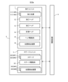
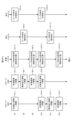
- FIG. 2 is a block diagram showing the configuration of the processing system in the first embodiment.
- FIG. 3 is a perspective view showing the configuration of a processing head that performs removal processing.
- FIG. 4 is a cross-sectional view showing the configuration of a processing head that performs additional processing.
- FIG. 5 is a perspective view showing the configuration of the measuring head.
- FIG. 6 is a flow chart showing the flow of machining operations by the machining system.
- FIG. 7 is a flow chart showing the flow of machining operations by the machining system.
- FIG. 8 is a flow chart showing the flow of machining operations by the machining system.
- FIG. 6 is a flow chart showing the flow of machining operations by the machining system.
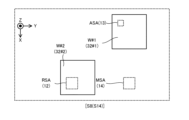
- FIG. 9 is a plan view showing the positional relationship between two machining heads (two machining areas), a measurement head (measurement area), and two stages (two workpieces) when one process of machining operation is performed.
- FIG. 10 is a plan view showing the positional relationship between two machining heads (two machining areas), a measurement head (measurement area), and two stages (two workpieces) when one process of machining operation is performed.
- 11(a) and 11(b) are cross-sectional views showing a modeled object formed on a work.
- FIG. 12 is a plan view showing the positional relationship between two machining heads (two machining areas), a measurement head (measurement area), and two stages (two workpieces) when one process of machining operation is performed. be.
- FIG. 12 is a plan view showing the positional relationship between two machining heads (two machining areas), a measurement head (measurement area), and two stages (two workpieces) when one process of machining operation is performed. be.
- FIG. 13 is a plan view showing the positional relationship between two machining heads (two machining areas), a measurement head (measurement area), and two stages (two workpieces) when one process of machining operation is performed.
- FIG. 14 is a plan view showing the positional relationship between two machining heads (two machining areas), a measurement head (measurement area), and two stages (two workpieces) when one process of machining operation is performed.
- FIG. 15 is a cross-sectional view showing an example of another shaping portion that prevents irradiation of the processing light to the removal processing target portion of the one shaping portion.
- FIG. 16 is a cross-sectional view showing processing light applied to a removal processing target portion of one modeling portion shown in FIG. 15 .
- FIG. 17 is a cross-sectional view showing an example of another shaping portion that prevents irradiation of the processing light to the removal processing target portion of the one shaping portion.
- FIG. 18 is a cross-sectional view showing processing light applied to a removal processing target portion of one modeling portion shown in FIG. 17 .
- FIG. 19 is a perspective view showing the configuration of a processing system in a modified example.
- FIG. 20 is a perspective view showing the configuration of a processing system in a modified example.
- FIG. 21 is a perspective view showing the configuration of a processing system in a modified example.
- FIG. 22 is a perspective view showing the configuration of a processing system in a modified example.
- FIG. 23 is a perspective view showing the configuration of a processing system in a modified example.
- FIG. 24 is a cross-sectional view showing the configuration of a processing system in a modified example.
- FIG. 25 is a perspective view showing the configuration of the processing system according to the second embodiment.
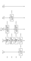
- FIG. 26 is a block diagram showing the configuration of a processing system according to the third embodiment.
- FIG. 27 is a perspective view showing the configuration of the processing system according to the fourth embodiment.
- FIG. 28 is a cross-sectional view showing the configuration of the light receiving device.
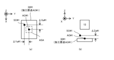
- FIGS. 29(a) and 29(b) shows an example of the processing baseline.
- FIGS. 30(a) and 30(b) shows an example of the processing baseline.
- FIGS. 31(a) and 31(b) shows an example of the processing baseline.
- FIG. 35 is a cross-sectional view showing the configuration of the light receiving device according to the fifth embodiment.
- FIG. 36 is a plan view showing the supply trace of the modeling material formed on the workpiece W.
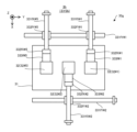
- FIG. 37 is a plan view showing the configuration of the stage driving system in the sixth embodiment.
- FIG. 38 is a cross-sectional view showing the stage in the sixth embodiment.
- FIG. 39 is a plan view showing the configuration of the stage unit in the seventh embodiment.
- FIG. 40 is a plan view showing the configuration of the stage unit in the eighth embodiment.
- FIG. 41 is a plan view showing the configuration of the stage drive system in the ninth embodiment.
- FIG. 42 is a plan view showing the configuration of the stage drive system in the ninth embodiment.
- FIG. 43 is a plan view showing the configuration of the stage driving system in the ninth embodiment.
- FIG. 44 is a plan view showing the configuration of the stage drive system in the ninth embodiment.
- FIG. 45 is a plan view showing the configuration of the stage drive system in the ninth embodiment.
- each of the X-axis direction and the Y-axis direction is the horizontal direction (that is, a predetermined direction in the horizontal plane), and the Z-axis direction is the vertical direction (that is, the direction perpendicular to the horizontal plane). and substantially in the vertical direction).
- the directions of rotation (in other words, tilt directions) about the X-, Y-, and Z-axes are referred to as the .theta.X direction, the .theta.Y direction, and the .theta.Z direction, respectively.
- the Z-axis direction may be the direction of gravity.
- the XY plane may be set horizontally.
- processing system SYS of the first embodiment
- processing system SYSa the processing system SYS in the first embodiment
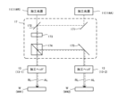
- FIG. 1 is a perspective view showing the configuration of the machining system SYSa.
- FIG. 2 is a block diagram showing the configuration of the machining system SYSa.
- the processing system SYSa includes a processing unit 1, a stage unit 3, and a control device 4.
- the processing unit 1 and the stage unit 3 are accommodated in the housing 5 . That is, the processing unit 1 and the stage unit 3 are arranged in the accommodation space SP inside the housing 5 . However, at least part of the processing unit 1 and the stage unit 3 may not be housed in the housing 5 .
- the processing system SYSa does not have to include the housing 5 that houses the processing unit 1 and the stage unit 3 .
- the processing unit 1 can process the work W by irradiating the work W with the processing light L under the control of the control device 4 .
- a work W is an object to be processed by the processing unit 1 .
- the work W may be, for example, a metal, an alloy (for example, duralumin), a semiconductor (for example, silicon), a resin, or CFRP. (Carbon Fiber Reinforced Plastic) or other composite materials, glass, ceramics, or any other material may be used. Examples of optional materials include at least one of gypsum, rubber such as polyurethane, and elastomers.
- a part of the work W may be made of a certain material, and the other part may be made of a different material.
- the processing unit 1 includes a processing light source 11, a processing head 12, a processing head 13, a measuring head 14, a head drive system 15, and a position detection device 16.
- the processing light source 11 emits at least one of infrared light, visible light, ultraviolet light, and extreme ultraviolet light as processing light L under the control of the control device 4 .
- the processing light L may contain pulsed light (that is, a plurality of pulsed beams).
- the processing light L may be laser light.
- the processing light source 11 may include a laser light source (for example, a semiconductor laser such as a laser diode (LD: Laser Diode)).
- the laser light source may include at least one of fiber lasers, CO2 lasers, YAG lasers, excimer lasers, and the like.
- the processing light L may not be laser light.
- the processing light source 11 may include any light source (for example, at least one of an LED (Light Emitting Diode) and a discharge lamp).
- Each of the processing heads 12 and 13 processes the work W by irradiating the work W with the processing light L emitted by the processing light source 11 under the control of the control device 4 .
- each of processing heads 12 and 13 may be referred to as a processing device.
- the processing head 12 may use the processing light L to perform the first processing on the workpiece W.
- the processing head 13 may use the processing light L to perform the second processing on the work W.
- the first process may be the same type of process as the second process. Alternatively, the first process may be a different type of process than the second process.
- At least one of the first and second machining may include removal machining for removing part of the workpiece W.
- At least one of the first and second processing may include additional processing for adding a new modeled object to the workpiece W.
- At least one of the first and second processing may include melt processing in which at least a portion of the surface of the workpiece W is melted. Melt processing may be processing for smoothing at least a portion of the surface of the workpiece W. In this case, melt processing may be referred to as smoothing or abrasive processing.
- at least one of the first processing and the second processing may be a joining processing for joining a plurality of works W.
- the joining process may include, for example, joining a plurality of works W by welding or the like.
- At least one of the first processing and the second processing may be cutting processing for cutting the workpiece W. In the first embodiment, an example in which the processing head 12 performs removal processing and the processing head 13 performs addition processing will be described.
- the removal processing may include thermal processing.
- the processing head 12 may irradiate the processing light L onto the region of the workpiece W to be processed.
- the energy of the processing light L is transmitted to the region to be processed and a portion adjacent to the region to be processed in the workpiece W.
- the heat resulting from the energy of the processing light L is transferred, the heat resulting from the energy of the processing light L melts the material forming the processing target region and the portion adjacent to the processing target region of the workpiece W.
- the melted material becomes droplets and scatters.
- the melted material evaporates due to the heat resulting from the energy of the processing light L.
- the processing head 12 performs the removal processing of the workpiece W using the principle of so-called thermal processing.
- the processing light L may include pulsed light or continuous light whose emission time is milliseconds or more.
- the processing head 12 may perform removal processing of the workpiece W using the principle of non-thermal processing (for example, ablation processing). That is, the processing head 12 may perform non-thermal processing (for example, ablation processing) on the workpiece W.
- non-thermal processing for example, ablation processing
- the material forming the processing target region and the portion adjacent to the processing target region of the workpiece W instantly evaporates and scatters. That is, the material forming the area to be processed and the portion adjacent to the area to be processed in the work W evaporates and scatters within a time sufficiently shorter than the thermal diffusion time of the work W.
- the material forming the area to be processed and the portion adjacent to the area to be processed of the work W is emitted from the work W as at least one of ions, atoms, radicals, molecules, clusters, and solid pieces. good too.
- the processing light L may include pulsed light with an emission time of picoseconds or less (or, in some cases, nanoseconds or femtoseconds or less).
- pulsed light with an emission time of picoseconds or less or, in some cases, nanoseconds or femtoseconds or less
- the processing target region and the portion adjacent to the processing target region of the workpiece W are configured. Materials may also sublime without going through the molten state.
- the processing head 13 may perform additional processing based on any processing method.
- 1st Embodiment demonstrates the example which the processing head 13 performs additional processing based on the laser build-up welding method (LMD:Laser Metal Deposition). Additional processing based on the laser build-up welding method melts the modeling material M supplied to the work W with processing light L (that is, an energy beam having the form of light), so that it is integrated with the work W or the work W It is an additional process that forms a modeled object that can be separated from.
- the processing head 13 may perform additional processing based on a method different from the laser build-up welding method.
- the processing head 13 uses a powder bed fusion method such as selective laser sintering (SLS), a binder jetting method (binder jetting), or a material jetting method. Additional processing based on at least one of (Material Jetting), stereolithography, and laser metal fusion (LMF) may be performed.
- SLS selective laser sintering
- binder jetting binder jetting
- LMF laser metal fusion
- the modeling material M is a material that can be melted by irradiation with processing light L having a predetermined intensity or higher.
- a modeling material M for example, at least one of a metallic material and a resinous material can be used.
- the modeling material M other materials different from the metallic material and the resinous material may be used. Examples of other materials include at least one of metal powder, alloy powder, resin, gypsum, rubber such as polyurethane, and elastomer.
- the modeling material M may contain the same material as the material forming the workpiece W.
- the modeling material M may include a material similar in composition to the material that constitutes the workpiece W.
- the modeling material M may contain a material different from the material forming the workpiece W.
- the building material M is a powdery or granular material. That is, the modeling material M is a granular material. However, the modeling material M does not have to be granular.
- the modeling material M at least one of a wire-like modeling material and a gaseous modeling material may be used.
- the machining heads 12 and 13 may process the workpiece W using the machining light L emitted from the single machining light source 11 .
- the machining heads 12 and 13 may process the workpiece W using different machining lights L emitted from different machining light sources 11 .
- the processing head 12 processes the workpiece W using the processing light L emitted by the first processing light source 11, and the processing head 13 uses the second processing light source different from the first processing light source 11.
- An example of processing a workpiece W using the processing light L emitted by the processing light source 11 will be described.
- the first processing light source 11 will be referred to as "processing light source 11R" and the second processing light source 11 will be referred to as "processing light source 11A" as necessary. distinguish.
- the processing light L emitted by the processing light source 11R is referred to as "processing light RL”
- the processing light L emitted by the processing light source 11A is referred to as "processing light AL" to distinguish between the two.
- Pulsed light may be used as the processing light RL used by the processing head 12 to remove and process the workpiece W.
- the processing light RL may be pulsed light whose pulse width is on the order of femtoseconds, picoseconds, or nanoseconds.
- the processing light source 11R may emit pulsed light (for example, pulsed light whose pulse width is on the order of femtoseconds, picoseconds, or nanoseconds) as the processing light RL.
- pulsed light for example, pulsed light whose pulse width is on the order of femtoseconds, picoseconds, or nanoseconds
- light different from pulsed light for example, continuous light may be used as the processing light RL.
- Continuous light may be used as the processing light AL used by the processing head 13 to additionally process the workpiece W.
- the processing light source 11A may emit continuous light as the processing light AL.
- light different from continuous light for example, pulsed light
- the machining head 12 performs removal machining on the workpiece W placed on the stage 32, which will be described later. That is, removal processing is performed on the stage 32 .
- the machining head 13 performs additional machining on the workpiece W placed on the stage 32 . In other words, additional processing is performed on the stage 32 .
- the work W machined using at least one of the machining heads 12 and 13 may be referred to as "work W".
- work W an object that is a combination of a work W and a modeled object added to the work W (this modeled object may be a modeled object after additional processing has been completed or may be a modeled object in the middle of additional processing).
- this modeled object may be a modeled object after additional processing has been completed or may be a modeled object in the middle of additional processing).
- workpiece W the workpiece W removed by using the machining head 12
- the modeled object may include not only an object modeled by additional processing, but also an object modeled by removal processing.
- the operation of modeling the modeled object may include at least one of the operation of modeling the modeled object by additional processing and the operation of modeling the modeled object by removal processing.
- the removal process also forms a tangible object.
- the processing head 12 performs removal processing of the work W
- the work W partially removed by the removal processing may be referred to as a modeled object.
- the processing head 12 may be arranged above the stage 32 on which the workpiece W is placed.
- the processing head 12 may be attached to a gate-shaped support frame 6 arranged on a surface plate 31 provided in the stage unit 3 .
- the support frame 6 may include a pair of leg members 61 protruding from the surface plate 31 along the Z-axis direction, and a beam member 62 connecting the pair of leg members 61 via the upper ends of the pair of leg members 61. good.
- the beam member 62 may be arranged above the stage 32 .
- the processing head 12 (more specifically, the head housing 120 described in FIG. 3) may be attached to this beam member 62 . Incidentally, in the example shown in FIG.
- the processing head 12 is attached to the beam member 62 via a head drive system 15, which will be described later.
- the processing head 12 may irradiate the work W with the processing light RL by emitting the processing light RL downward from the processing head 12 . That is, the machining head 12 may irradiate the workpiece W with the machining light RL traveling along the Z-axis direction by emitting the machining light RL traveling along the Z-axis direction.
- the processing head 13 may be arranged above the stage 32 on which the workpiece W is placed. Specifically, the processing head 13 may be attached to the beam member 62 similarly to the processing head 12 . In the example shown in FIG. 1, the processing head 13 (more specifically, the head housing 130 described with reference to FIG. 4) is attached to the beam member 62 via the head drive system 15 described later.
- the processing head 13 may irradiate the work W with the processing light AL by emitting the processing light AL downward from the processing head 13 . That is, the processing head 13 may irradiate the workpiece W with the processing light AL traveling along the Z-axis direction by emitting the processing light AL traveling along the Z-axis direction.
- the direction of viewing at least one of the processing heads 12 and 13 from the stage 32 includes a vertical component or a gravity direction component. It may contain states.
- FIG. 3 is a perspective view showing the configuration of the processing head 12.
- FIG. 4 is a cross-sectional view showing the configuration of the processing head 13. As shown in FIG.
- the processing head 12 may include, for example, a focus changing optical system 121, a galvanomirror 122, and an f ⁇ lens 123.
- the focus changing optical system 121 , the galvanomirror 122 and the f ⁇ lens 123 may be accommodated in the head housing 120 .
- the processing head 12 may not include the focus changing optical system 121 .
- the focus changing optical system 121 is an optical member capable of changing the focus position of the processing light RL (that is, the convergence position of the processing light RL) along the traveling direction of the processing light RL.
- the focus changing optical system 121 may include, for example, a plurality of lenses arranged along the traveling direction of the processing light RL. In this case, the focus position of the processing light RL may be changed by moving at least one of the plurality of lenses along the optical axis direction.
- the processing light RL that has passed through the focus changing optical system 121 is incident on the galvanomirror 122 .
- the galvanomirror 122 changes the emission direction of the processing light RL from the galvanomirror 122 by deflecting the processing light RL (that is, changing the emission angle of the processing light RL).
- the position at which the processing light RL is emitted from the processing head 12 is changed.
- the target irradiation area RA onto which the processing light RL is irradiated on the surface of the work W is changed.
- the target irradiation area RA may be a portion where the light intensity is equal to or greater than a predetermined threshold.
- a predetermined threshold value for example, 0, a value that is 1/e2 times the maximum light intensity of the light spot, a value that is half the maximum light intensity of the light spot, and a value that is half the maximum light intensity of the light spot. At least one such as 1/n (n is any real number) may be used.
- the galvanomirror 122 includes, for example, an X scanning mirror 122X and a Y scanning mirror 122Y.
- Each of the X scanning mirror 122X and the Y scanning mirror 122Y is a tilt angle variable mirror that can change the angle with respect to the optical path of the processing light RL incident on each mirror.
- the X scanning mirror 122X reflects the processing light RL toward the Y scanning mirror 122Y.
- the X scanning mirror 122X can swing or rotate around a rotation axis along the Y axis. By swinging or rotating the X scanning mirror 122X, the processing light RL scans the surface of the workpiece W along the X-axis direction.
- the target irradiation area RA moves on the surface of the workpiece W along the X-axis direction by swinging or rotating the X scanning mirror 122X.
- Y scanning mirror 122 Y reflects processing light RL toward f ⁇ lens 123 .
- the Y scanning mirror 122Y can swing or rotate around a rotation axis along the X axis.
- the processing light RL scans the surface of the workpiece W along the Y-axis direction.
- the target irradiation area RA moves on the surface of the workpiece W along the Y-axis direction.
- the galvanomirror 122 may move the irradiation position of the processing light RL with which the surface of the work W is irradiated.
- Such a galvanomirror 122 enables the processing light RL to scan or sweep the processing area RSA determined with the processing head 12 as a reference. That is, the galvanomirror 122 enables the target irradiation area RA to move within the processing area RSA determined with the processing head 12 as a reference.
- the machining area RSA indicates an area (in other words, a range) where removal machining is performed by the machining head 12 while the positional relationship between the machining head 12 and the workpiece W is fixed (that is, without being changed).
- the processing area RSA is a region that matches or is narrower than the scanning range of the processing light RL deflected by the galvanomirror 122 while the positional relationship between the processing head 12 and the workpiece W is fixed. is set to be Further, by moving the processing head 12 by the head driving system 15 and/or by moving the stage 32 by the stage driving system 33, the processing area RSA (target irradiation area RA) is moved on the surface of the workpiece W relative to each other. can move freely. Incidentally, depending on the height of the surface of the work W, the processing head 12 may be moved in the Z-axis direction (direction intersecting the surface of the work W) by the head drive system 15, or the stage 32 may be moved by the stage drive system 33. Alternatively, the focus changing optical system 12 may be used to change the focus position. At least two of these three methods may be used in combination.
- the f ⁇ lens 123 is an optical system for emitting the processing light RL from the galvanomirror 122 toward the work W.
- the f ⁇ lens 123 is an optical element capable of condensing the processing light RL from the galvanomirror 122 onto the condensing surface.
- the condensing surface of the f ⁇ lens 123 may be set on the surface of the workpiece W, for example.
- the condensing surface of the f.theta The condensing plane of the f.theta.
- the galvanometer mirror 122 may be arranged at the front focal position of the f ⁇ lens 123 (when the galvanometer mirror 122 includes a plurality of scanning mirrors (X scanning mirror 122X and Y scanning mirror 122Y), the f ⁇ lens
- the front focal position of 123 may be set between multiple scanning mirrors).
- the processing head 13 includes an irradiation optical system 131 and a material nozzle 132.
- the processing head 13 has a plurality of material nozzles 132 , but the processing head 13 may have a single material nozzle 132 .
- the irradiation optical system 131 and the material nozzle 132 may be housed in the head housing 130 .
- the irradiation optical system 131 is an optical system (for example, a condensing optical system) for irradiating the workpiece W with the processing light AL. Therefore, the irradiation optical system 131 may be called a beam irradiation unit. Specifically, the irradiation optical system 131 processes a target irradiation area AA set on or in the vicinity of the workpiece W as an area irradiated (typically, condensed) with the processing light AL. Light AL can be applied.
- the processing area ASA where additional processing is performed by the processing head 13 while the positional relationship between the processing head 13 and the workpiece W is fixed is the target irradiation area. May be consistent with AA.
- the processing area ASA target irradiation area AA moves over the surface of the workpiece W by moving the processing head 13 by the head drive system 15 and/or by moving the stage 32 by the stage drive system 33, which will be described later. Relatively movable.
- the processing head 13 may be moved in the Z-axis direction (direction intersecting the surface of the work W) by the head drive system 15, or the stage 32 may be moved by the stage drive system 33. may be moved in the Z-axis direction.
- the positional relationship between the machining area ASA where the machining head 13 performs additional machining and the machining area RSA where the machining head 12 performs removal machining may be information known to the machining system SYSa.
- the working area ASA and the working area RSA may be pre-aligned.
- the target irradiation area AA may be a portion where the light intensity is greater than or equal to a predetermined threshold.
- a predetermined threshold value for example, 0, a value that is 1/e2 times the maximum light intensity of the light spot, a value that is half the maximum light intensity of the light spot, and a value that is half the maximum light intensity of the light spot. At least one such as 1/n (n is any real number) may be used.
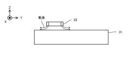
- the material nozzle 132 supplies (for example, injects, jets, ejects, or sprays) the modeling material M.
- material nozzle 132 may be referred to as a material supply or material supply member.
- the material nozzle 132 is physically connected to a material supply source (not shown) that supplies the modeling material M. As shown in FIG. Material nozzle 132 supplies modeling material M supplied from a material supply source.
- the material nozzle 132 supplies the modeling material M to the irradiation position of the processing light AL (that is, the target irradiation area AA or processing area ASA irradiated with the processing light AL from the irradiation optical system 131). More specifically, in the first embodiment, a molten pool is formed in the work W when the work W is irradiated with the processing light AL.
- the molten pool is a pool of metal melted by the irradiation of the processing light AL (for example, metal forming part of the workpiece W).
- a material nozzle 132 may supply build material M to the weld pool. However, the material nozzle 132 does not have to supply the modeling material M to the molten pool.
- the processing head 13 may cause the irradiation optical system 131 to melt the modeling material M from the material nozzle 132 before the modeling material M reaches the work W, and adhere the melted modeling material M to the work W. .
- the measurement head 14 can measure (in other words, measure) the object to be measured under the control of the control device 4 .
- the metrology head 14 may also be referred to as a metrology device, a measurement head, or a measurement device.
- the measurement head 14 can measure any property of the object to be measured.
- An example of the characteristics of the measurement object is the position of the measurement object.
- Another example of the properties of the object to be measured is the shape of the object to be measured (for example, two-dimensional shape or three-dimensional shape).
- Another example of the properties of the object to be measured is at least one of the reflectance of the object to be measured, the transmittance of the object to be measured, the surface roughness of the object to be measured, and the like.
- the object to be measured may include the workpiece W.
- the objects to be measured are the work W that has not yet been processed by the processing unit 1, the work W that has been removed by the processing head 12, the work W that has been additionally processed by the processing head 13, and the processing unit. 1 may include at least one of the workpieces W that has been machined.
- the object to be measured may include a stage 32 on which the workpiece W can be placed.
- the object to be measured may include a modeled object formed on the work W. FIG.
- the measurement head 14 may be arranged above the stage 32 on which the workpiece W is placed. Specifically, the measurement head 14 may be attached to the beam member 62 in the same manner as the processing heads 12 and 13 . In the example shown in FIG. 1, the measurement head 14 is attached to the beam member 62 via a head drive system 15, which will be described later. When the measurement head 14 is arranged above the stage 32, the measurement head 14 may measure the work W from above. The measurement head 14 may measure the stage 32 from above the stage 32 . The measurement head 14 may measure the modeled object from above the modeled object.
- the measurement head 14 may measure the measurement object using any method.
- the measurement head 14 may optically, electrically, magnetically, physically, chemically or thermally measure the measurement object.
- the measurement head 14 may measure the measurement target without contacting the measurement target.
- the measurement head 14 may measure the measurement target by contacting the measurement target. In the first embodiment, an example will be described in which the measurement head 14 optically measures a measurement target without contacting the measurement target.
- FIG. 5 is a perspective view showing the configuration of the measurement head 14. As shown in FIG.
- the measurement head 14 measures the measurement object in units of measurement areas MSA. That is, the measurement head 14 measures the measurement area MSA set on the measurement object. In other words, the measurement head 14 measures the measurement target portion in which the measurement area MSA is set in the measurement target.
- the measurement area MSA indicates an area (in other words, range) in which measurement is performed by the measurement head 14 while the positional relationship between the measurement head 14 and the object to be measured is fixed (that is, without being changed).
- the measurement head 14 may include an irradiation optical system 141 and a light receiving element 142 in order to measure the workpiece W in units of measurement areas MSA.
- the irradiation optical system 141 and the light receiving element 142 may be housed in the head housing 140 .
- the irradiation optical system 141 irradiates the measurement light ML onto the measurement target (in particular, the measurement area MSA on the measurement target).
- the light receiving element 142 receives return light from the measurement object irradiated with the measurement light ML (in particular, the measurement area MSA on the measurement object).
- the measurement head 14 may not include the light receiving element 142 . That is, the return light may be received by the light receiving element 142 arranged at a position away from the measurement head 14 . Further, the light receiving element 142 may receive the return light via at least part of the irradiation optical system 141 .
- the measurement head 14 may measure the measurement object using a light section method that projects slit light onto the surface of the measurement object and measures the shape of the projected slit light.
- the irradiation optical system 141 may irradiate the measurement object with slit light as the measurement light ML.
- the measurement head 14 may measure the measurement target using white interferometry that measures an interference pattern between white light that has passed through the measurement target and white light that has not passed through the measurement target.
- the irradiation optical system 141 may irradiate the measurement object with white light as the measurement light ML.
- the measurement head 14 may measure the measurement object by projecting pattern light onto the surface of the measurement object and measuring the shape of the projected pattern light.
- the irradiation optical system 141 may irradiate the measurement object with the pattern light as the measurement light ML.
- the measurement head 14 may be provided with a plurality of measuring instruments each capable of measuring a measurement object.
- At least one of the plurality of measuring instruments may include, for example, the irradiation optical system 141 and the light receiving element 142 described above.
- the plurality of measuring instruments may include at least two measuring instruments with different measurement resolutions (in other words, different measurement accuracies).
- the plurality of meters may include at least two meters with different sizes of measurement areas MSA.
- the head drive system 15 moves at least one of the processing head 12, the processing head 13, and the measurement head 14 under the control of the control device 4.
- the head drive system 15, under the control of the control device 4 drives at least one of the processing head 12, the processing head 13, and the measurement head 14 in the X-axis, Y-axis, Z-axis, ⁇ X-direction, ⁇ Y-direction, and ⁇ Z-direction.
- the head driving system 15 may also be called a moving device or a driving device.
- the head drive system 15 moves the processing head 12, the processing head 13, and the measurement head 14 along the Y-axis direction and the Z-axis direction, respectively. That is, in the first embodiment, the head drive system 15 drives the processing head 12, the processing head 13, and the measurement head 14 respectively in the Z-axis direction, which is the traveling direction of the processing light beams RL and AL, and in the traveling direction of the processing light beams RL and AL.
- the Z-axis direction which is the traveling direction of the processing light beams RL and AL
- An example of moving along each of the Y-axis directions that intersect the direction will be described. In this case, as shown in FIG.
- the head driving system 15 includes a Y guide member 151Y#1, a Y guide member 151Y#2, a Y block member 152Y#1, a Y block member 152Y#2, and a Y block.
- a member 152Y#3, a Z guide member 151Z#1, a Z guide member 151Z#2, and a Z guide member 151Z#3 may be provided.
- Each of the Y guide members 151Y#1 and 151Y#2 is a shaft member extending along the Y-axis direction.
- Each of the Y guide members 151Y#1 and 151Y#2 is arranged on the beam member 62 . Therefore, the beam member 62 may be a member extending along the Y-axis direction.
- the Y block member 152Y#1 is attached to the Y guide member 151Y#1 so that the Y block member 152Y#1 can move along the Y guide member 151Y#1.
- the Y block member 152Y#2 is attached to the Y guide member 151Y#2 so that the Y block member 152Y#2 can move along the Y guide member 151Y#2.
- the Y block member 152Y#3 is attached to the Y guide member 151Y#1 so that the Y block member 152Y#3 can move along the Y guide member 151Y#1.
- Each of the Z guide members 151Z#1 to 151Z#3 is a shaft member extending along the Z-axis direction.
- Z guide members 151Z#1 to 151Z#3 are arranged on Y block members 152Y#1 to 152Y#3, respectively.
- the processing head 12 is attached to the Z guide member 151Z#1 so that the processing head 12 can move along the Z guide member 151Z#1.
- the processing head 13 is attached to the Z guide member 151Z#2 so that the processing head 13 can move along the Z guide member 151Z#2.
- the measuring head 14 is attached to the Z guide member 151Z#3 so that the measuring head 14 can move along the Z guide member 151Z#3.
- the processing head 12 attached to the Y block member 152Y#1 via the Z guide member 151Z#1 moves in the Y-axis direction. move along. Furthermore, the machining head 12 moves along the Z-axis direction by moving the machining head 12 along the Z guide member 151Z#1. Therefore, the Y guide member 151Y#1, the Y block member 152Y#1, and the Z guide member 151Z#1 may be regarded as capable of functioning as a moving device (driving device) capable of moving the processing head 12.
- the processing head 13 attached to the Y block member 152Y#2 via the Z guide member 151Z#2 moves in the Y-axis direction. move along. Furthermore, the machining head 13 moves along the Z-axis direction by moving the machining head 13 along the Z guide member 151Z#2. Therefore, the Y guide member 151Y#2, the Y block member 152Y#2, and the Z guide member 151Z#2 may be regarded as capable of functioning as a moving device (driving device) capable of moving the processing head 13.
- the measurement head 14 attached to the Y block member 152Y#3 via the Z guide member 151Z#3 moves in the Y-axis direction. move along. Furthermore, the measurement head 14 moves along the Z-axis direction by moving the measurement head 14 along the Z guide member 151Z#3. Therefore, the Y guide member 151Y#1, the Y block member 152Y#3, and the Z guide member 151Z#3 may be regarded as capable of functioning as a moving device (driving device) capable of moving the measurement head 14.
- the processing heads 12 and 13 move along two different Y guide members 151Y#1 and 151Y#2, respectively.
- each of processing heads 12 and 13 may move along a single Y guide member (eg, Y guide member 151Y#1 or 151Y#2).
- the processing head 12 and the measurement head 14 move along the single Y guide member 151Y#1.
- the processing head 12 and the measurement head 14 may each move along two different Y guide members (eg, Y guide members 151Y#1 and 151Y#2).
- the processing head 13 and the measurement head 14 move along two different Y guide members 151Y#1 and 151Y#2, respectively.
- each of the processing head 13 and the measurement head 14 may move along a single Y guide member (eg, Y guide member 151Y#1 or 151Y#2).
- the processing head 12, the processing head 13, and the measurement head 14 may each move along three different Y guide members.
- the processing head 12 and the measurement head 14 move within the first space SP1 of the housing space SP of the housing 5, and the processing head 13 moves within the housing space SP of the housing 5. It is moving in a second space SP2 different from the first space SP1.
- the modeling material M supplied to the work W in order for the processing head 13 to process the work W enters the first space SP1. become difficult. Therefore, the influence of the modeling material M on the removal processing by the processing head 12 and the measurement by the measurement head 14 is reduced.
- the arrangement positions of the processing head 12, the processing head 13, and the measuring head 14 are not limited to the example shown in FIG.
- At least one of the processing head 12 and the measurement head 14 may move within the second space SP2 in which the processing head 13 moves.
- the processing head 13 may move within the first space SP1 in which at least one of the processing head 12 and the measurement head 14 moves.
- the first space SP1 is a space located on one side (eg, +X side) of the support frame 6, and the second space SP2 is located on the other side (eg, -X side) of the support frame 6. ). That is, the first space SP1 is located at a different position from the second space SP2 along the X-axis direction. The first space SP1 is located at a different position from the second space SP2 along the X-axis direction, which is the moving direction of the stage 32, which will be described later.
- the arrangement positions of the first space SP1 and the second space SP2 are not limited to the example shown in FIG.
- the first space SP1 and the second space SP2 are adjacent to each other, but the first space SP1 and the second space SP2 may be separate spaces. Alternatively, part of the first space SP1 and part of the second space SP2 may overlap.
- the head drive system 15 moves the processing head 12
- the positional relationship between the processing head 12 and the stage 32 changes.
- the head drive system 15 may be regarded as capable of functioning as a position changing device capable of changing the positional relationship between the processing head 12 and the stage 32 and the work W, respectively.
- the processing area RSA where the processing head 12 performs removal processing moves with respect to the stage 32 and the workpiece W, respectively. From a different point of view, the stage 32 and the workpiece W move relative to the machining area RSA where the machining head 12 performs removal machining.
- the head drive system 15 moves the processing head 13, the positional relationship between the processing head 13, the stage 32, and the work W changes. Therefore, the head drive system 15 may be regarded as capable of functioning as a position changing device capable of changing the positional relationship between the processing head 13 and the stage 32 and the workpiece W, respectively. Furthermore, when the head driving system 15 moves the processing head 13, the processing area ASA where the processing head 13 performs additional processing moves with respect to the stage 32 and the workpiece W, respectively. From a different point of view, the stage 32 and the workpiece W move relative to the machining area ASA where the machining head 13 performs additional machining.
- the head drive system 15 moves the measurement head 14, the positional relationship between the measurement head 14, the stage 32, and the workpiece W changes. For this reason, the head drive system 15 may be regarded as capable of functioning as a position changing device capable of changing the positional relationship between the measurement head 14 and the stage 32 and workpiece W, respectively. Furthermore, when the head drive system 15 moves the measurement head 14, the measurement area MSA where the measurement head 14 measures with respect to each of the stage 32 and the workpiece W moves. From a different point of view, the stage 32 and the workpiece W move relative to the measurement area MSA where the measurement head 14 measures.
- the position detection device 16 can measure the respective positions of the processing head 12, the processing head 13, and the measurement head 14. That is, the position detection device 16 is a device capable of acquiring information regarding the positions of the processing head 12 , the processing head 13 and the measuring head 14 .
- Position detection device 16 may include, for example, an interferometer (eg, laser interferometer).
- the position detection device 16 may include, for example, an encoder (eg, at least one of a linear encoder and a rotary encoder). If the head drive system 15 uses a stepping motor as a drive source, the position detection device 16 may include, for example, an open-loop control type position detection device.
- the open-loop control type position detection device estimates the amount of movement of each of the processing head 12, the processing head 13, and the measurement head 14 from the integrated value of the number of pulses for driving the stepping motors, thereby determining the It is a position detection device that measures the respective positions of the processing head 13 and the measurement head 14 .
- the stage unit 3 includes a surface plate 31, a plurality of stages 32, a stage drive system 33, and a plurality of position detection devices 34.
- the surface plate 31 is arranged on the bottom surface of the housing 5 (or on a support surface such as a floor on which the housing 5 is placed).
- a stage 32 is arranged on the surface plate 31 .
- a non-illustrated damper for reducing transmission of vibration of the surface plate 31 to the stage 32 is provided between the support surface such as the bottom surface of the housing 5 or the floor on which the housing 5 is placed and the surface plate 31, a non-illustrated damper for reducing transmission of vibration of the surface plate 31 to the stage 32 is provided.
- a vibration device may be installed.
- the support frame 6 described above may be arranged on the surface plate 31 .
- a leg member may be provided between the surface plate 31 and the bottom surface of the housing 5 (or a support surface such as a floor on which the housing 5 is placed). In this case, a vibration isolator may be installed between the leg member and the surface plate 31 and/or between the leg member and the bottom surface (or support surface).
- the stage 32 is a mounting device on which the workpiece W is mounted.
- the stage 32 may be capable of holding the work W placed on the stage 32 .
- the stage 32 may not be able to hold the work W placed on the stage 32 .
- the workpiece W may be placed on the stage 32 without clamping.
- the stage 32 may include at least one of a mechanical chuck, an electrostatic chuck, a vacuum chuck, and the like to hold the work W.
- the stage unit 3 includes two stages 32 (specifically, stage 32#1 and stage 32#2).
- work W#1 the work W placed on stage 32#1
- work W#2 the work W placed on stage 32#2
- the machining head 12 may perform removal machining on the workpiece W#1 placed on the stage 32#1.
- the machining head 12 may perform removal machining on the workpiece W#2 placed on the stage 32#2.
- the machining head 13 may perform additional machining on the workpiece W#1 placed on the stage 32#1.
- the machining head 13 may perform additional machining on the work W#2 placed on the stage 32#2.
- the measurement head 14 may measure the workpiece W#1 placed on the stage 32#1 (furthermore, the stage 32#1).
- the measurement head 14 may measure the workpiece W#2 placed on the stage 32#2 (furthermore, the stage 32#2).
- the processing unit 1 performs at least one of removal processing and additional processing on the work W#1 placed on the stage 32#1, thereby integrating with the work W#1 or separating from the work W#1.
- a possible first build may be built.
- the processing unit 1 performs at least one of removal processing and additional processing on the work W#2 placed on the stage 32#2, thereby integrating with the work W#2 or separating from the work W#2.
- a possible second build may be built.
- the first modeled object and the second modeled object may be models similar to each other.
- the first modeled object and the second modeled object may be models that are similar to each other in at least one of size and shape.
- two objects that are similar to each other are not limited to “two objects that are partially different but are similar as a whole", as well as “two identical objects that have no differences”. It may also include “two shaped objects” and “two shaped objects that can be regarded as the same”.
- the processing system SYSa selects the second modeled object based on the modeling result of the first modeled object. You can shape.
- the processing system SYSa uses at least one of the processing heads 12 and 13 to model a first modeled object, uses the measurement head 14 to measure the first modeled object, and measures the first modeled object by the measurement head 14. Based on the results, at least one of the processing heads 12 and 13 may be used to form the second modeled object.
- control device 4 that controls the processing system SYSa calculates the difference between the actual shape of the first modeled object and the ideal shape of the first modeled object based on the measurement result of the first modeled object by the measurement head 14. is calculated, based on the calculated difference, the modeling conditions (processing conditions) of the second object are modified so as to form the second object having an ideal shape, and using the modified modeling conditions, At least one of the processing heads 12 and 13 may be controlled to form the second object.
- the stage drive system 33 moves at least one of the multiple stages 32 under the control of the control device 4 .
- the stage drive system 33 moves at least one of the stages 32 in at least one of the X-axis, Y-axis, Z-axis, ⁇ X-direction, ⁇ Y-direction and ⁇ Z-direction under the control of the control device 4. You can move along.
- the stage driving system 33 may be called a moving device or a driving device.
- the stage drive system 33 moves each of the multiple stages 32 (that is, the stages 32#1 and 32#2) along the X-axis direction. That is, the stage drive system 33 moves each of the plurality of stages 32 (that is, the stages 32#1 and 32#2) to the Z-axis direction, which is the traveling direction of the processing light beams RL and AL, and the processing head 12, the processing head 13, and the processing head 13.
- An example of moving the measurement heads 14 along the X-axis direction that intersects both the Y-axis direction, which is the moving direction of each, will be described.
- the stage drive system 33 may include an X guide member 331X#1 and an X guide member 331X#2.
- Each of the X guide members 331X#1 and 331X#2 is a shaft member extending along the X-axis direction.
- Each of the X guide members 331X#1 and 331X#2 is arranged on the platen 31 such that the X guide members 331X#1 and 331X#2 are separated along the Y-axis direction.
- the stage 32#1 is attached to the X guide member 331X#1 so that the stage 32#1 can move along the X guide member 331X#1.
- the stage 32#2 is attached to the X guide member 331X#2 so that the stage 32#2 can move along the X guide member 331X#2. Therefore, in the example shown in FIG. 1, the two stages 32#1 and 32#2 are arranged apart along the Y-axis direction.
- the X guide member 331X#1 may be regarded as capable of functioning as a moving device (driving device) capable of moving the stage 32#1.
- the stage 32#2 moves along the X-axis direction. Therefore, the X guide member 331X#2 may be regarded as capable of functioning as a moving device (driving device) capable of moving the stage 32#2.
- the processing head 12, the processing head 13 and the measurement head 14 are arranged above the stages 32#1 and 32#2. Therefore, the space in which the head drive system 15 moves the processing head 12, the processing head 13, and the measurement head 14, and the space in which the stage drive system 33 moves the stages 32#1 and 32#2 are arranged in the Z-axis direction (that is, , traveling directions of the processing beams RL and AL).
- the stage drive system 33 moves the stage 32, the positional relationships between the processing head 12, the processing head 13, and the measurement head 14, and the stage 32 and the workpiece W change. Therefore, the stage drive system 33 is considered to be capable of functioning as a position changing device capable of changing the positional relationship between the processing head 12, the processing head 13, and the measurement head 14, and the stage 32, and the workpiece W, respectively.
- the stage driving system 33 moves the stage 32, the machining area RSA where the machining head 12 performs removal machining, the machining area ASA where the machining head 13 performs additional machining, and the measurement area MSA where the measurement head 14 performs measurement. , the stage 32 and the workpiece W move.
- the plurality of position detection devices 34 can measure the positions of the plurality of stages 32 respectively.
- the plurality of position detection devices 34 are devices capable of acquiring information regarding the positions of the plurality of stages 32 respectively.
- the stage unit 3 since the stage unit 3 includes the two stages 32#1 and 32#2 as described above, the stage unit 3 has two position detectors 34 (specifically, position detectors 34). detectors 34#1 and 34#2).
- Position detectors 34#1 and 34#2 can measure the positions of stages 32#1 and 32#2, respectively.
- Position detection device 34 may include, for example, an interferometer (eg, a laser interferometer).
- the position detection device 34 may include, for example, an encoder (eg, at least one of a linear encoder and a rotary encoder).
- the position detection device 34 may include, for example, an open-loop control type position detection device.
- the open-loop control type position detection device is a position detection device that measures the position of the stage 32 by estimating the amount of movement of the stage 32 from the integrated value of the number of pulses for driving the stepping motor.
- the control device 4 controls the operation of the processing system SYSa. For example, the control device 4 generates processing control information for processing the work W, and controls the processing unit 1 and the stage unit based on the processing control information so that the work W is processed according to the generated processing control information. 3 may be controlled. That is, the control device 4 may control the machining of the workpiece W. For example, the control device 4 generates measurement control information for measuring a measurement object, and controls the processing unit 1 and the The stage unit 3 may be controlled. That is, the control device 4 may control the measurement of the measurement object.
- the control device 4 may include, for example, an arithmetic device and a storage device.
- the computing device may include, for example, at least one of a CPU (Central Processing Unit) and a GPU (Graphics Processing Unit).
- the control device 4 functions as a device that controls the operation of the machining system SYSa as the arithmetic device executes a computer program.
- This computer program is a computer program for causing the control device 4 (for example, arithmetic device) to perform (that is, execute) an operation to be performed by the control device 4, which will be described later. That is, this computer program is a computer program for causing the control device 4 to function so as to cause the machining system SYSa to perform the operation described later.
- the computer program executed by the arithmetic device may be recorded in a storage device (that is, a recording medium) included in the control device 4, or may be stored in the control device 4. Any storage that can be externally attached to the control device 4. It may be recorded on a medium (for example, hard disk or semiconductor memory). Alternatively, the computing device may download the computer program to be executed from a device external to the control device 4 via the network interface.
- a storage device that is, a recording medium
- the computing device may download the computer program to be executed from a device external to the control device 4 via the network interface.
- the control device 4 does not have to be provided inside the processing system SYSa.
- the control device 4 may be provided as a server or the like outside the processing system SYSa.
- the control device 4 may be provided as a computer (for example, a notebook computer) or the like that can be connected to the processing system SYSa.
- the control device 4 may be provided as a computer (for example, a notebook computer) installed near the processing system SYSa.
- the control device 4 and the processing system SYSa may be connected by a wired and/or wireless network (or data bus and/or communication line).
- a network using a serial bus interface represented by at least one of IEEE1394, RS-232x, RS-422, RS-423, RS-485 and USB may be used.
- a network using a parallel bus interface may be used as the wired network.
- a network using an Ethernet (registered trademark) interface represented by at least one of 10BASE-T, 100BASE-TX, and 1000BASE-T may be used.
- a network using radio waves may be used as the wireless network.
- An example of a network using radio waves is a network conforming to IEEE802.1x (for example, at least one of wireless LAN and Bluetooth (registered trademark)).
- a network using infrared rays may be used as the wireless network.
- a network using optical communication may be used as the wireless network.
- the control device 4 and the processing system SYSa may be configured to be able to transmit and receive various information via a network.
- the control device 4 may be capable of transmitting information such as commands and control parameters to the machining system SYSa via a network.
- the machining system SYSa may include a receiving device that receives information such as commands and control parameters from the control device 4 via the network.
- a first control device that performs part of the processing performed by the control device 4 is provided inside the processing system SYSa, while a second control device that performs another part of the processing performed by the control device 4 is provided.
- the control device may be provided outside the processing system SYSa.
- a computing model that can be constructed by machine learning may be implemented in the control device 4 by the computing device executing a computer program.
- An example of an arithmetic model that can be constructed by machine learning is an arithmetic model that includes a neural network (so-called artificial intelligence (AI)).
- learning the computational model may include learning neural network parameters (eg, at least one of weights and biases).
- the control device 4 may control the operation of the machining system SYS using the arithmetic model.
- the operation of controlling the operation of the machining system SYSa may include the operation of controlling the operation of the machining system SYSa using the arithmetic model.
- control device 4 may be equipped with an arithmetic model that has already been constructed by off-line machine learning using teacher data. Further, the arithmetic model installed in the control device 4 may be updated on the control device 4 by online machine learning.
- control device 4 may use a computation model implemented in a device external to the control device 4 (that is, a device provided outside the machining system SYSa). may be used to control the operation of the processing system SYSa.
- Recording media for recording computer programs executed by the arithmetic unit include CD-ROMs, CD-Rs, CD-RWs, flexible disks, MOs, DVD-ROMs, DVD-RAMs, DVD-Rs, DVD+Rs, DVD- At least one of optical discs such as RW, DVD+RW and Blu-ray (registered trademark), magnetic media such as magnetic tapes, magneto-optical discs, semiconductor memories such as USB memories, and other arbitrary media capable of storing programs are used.
- the recording medium may include a device capable of recording a computer program (for example, a general-purpose device or a dedicated device in which the computer program is implemented in at least one form of software, firmware, etc.).
- each process and function included in the computer program may be realized by a logical processing block realized in the control device 4 by the control device 4 (that is, computer) executing the computer program, It may be realized by hardware such as a predetermined gate array (FPGA Field Programmable Gate Array) provided in the control device 4, ASIC (Application Specific Integrated Circuit), etc., or a logical processing block and a part of hardware elements It may be realized in a form mixed with partial hardware modules to be realized.
- a logical processing block realized in the control device 4 by the control device 4 (that is, computer) executing the computer program
- hardware such as a predetermined gate array (FPGA Field Programmable Gate Array) provided in the control device 4, ASIC (Application Specific Integrated Circuit), etc.
- ASIC Application Specific Integrated Circuit
- FIG. 6 to 8 is a flow chart showing the flow of machining operation by the machining system SYSa.
- the first object BO1 is formed on stage 32#1 (that is, work W#1) and the second object BO1 is formed on stage 32#2 (that is, work W#2).
- a flow of processing operations for modeling the object BO2 will be described.
- work W#1 is first placed on stage 32#1 (step S1-1). Further, the work W#2 is placed on the stage 32#2 (step S1-2).
- step S2-1 the stage 32#1 moves to the measurement area where the measurement head 14 performs measurement. Specifically, as described above, the measurement head 14 irradiates the measurement area MSA with the measurement light ML, thereby measuring the portion of the object to be measured that overlaps the measurement area MSA. Therefore, in step S2-1, at least one of stage 32#1 and measurement head 14 is moved so that at least a portion of stage 32#1 overlaps measurement area MSA. In other words, at least one of stage 32#1 and measurement head 14 moves so that at least part of workpiece W#1 overlaps measurement area MSA.
- machining head 12 (machining area RSA), machining head 13 (machining area ASA), measuring head 14 (measuring area MSA), stage 32#1 (workpiece W#1) and stage 32#2 (workpiece W#2) ) is the positional relationship shown in FIG.
- the measurement head 14 measures the workpiece W#1 placed on the stage 32#1 (step S2-2).
- a measurement result of the workpiece W#1 by the measurement head 14 is output to the control device 4.
- FIG. The control device 4 may specify the position of the work W#1 on the stage 32#1 based on the measurement result of the work W#1 by the measurement head 14.
- FIG. The control device 4 may specify the shape of the work W#1 placed on the stage 32#1 based on the measurement result of the work W#1 by the measuring head 14.
- the control device 4 can control each of the machining heads 12 and 13 so as to machine the work W#1 having the specified shape placed at the specified position. Become.
- step S3-1 at least one of the stage 32#1 and the processing head 13 moves so that at least a portion of the stage 32#1 overlaps the processing area ASA. In other words, at least one of the stage 32#1 and the processing head 13 moves so that at least a portion of the work W#1 overlaps the processing area ASA.
- stage 32#2 relatively moves to the measurement area where the measurement head 14 measures (step S3-2). Specifically, at least one of stage 32#2 and measurement head 14 moves so that at least part of stage 32#2 overlaps measurement area MSA. In other words, at least one of stage 32#2 and measurement head 14 moves so that at least part of workpiece W#2 overlaps measurement area MSA.
- machining head 12 machining area RSA
- machining head 13 machining area ASA
- measuring head 14 measuring area MSA
- stage 32#1 workpiece W#1
- stage 32#2 workpiece W#2
- the machining head 13 performs additional machining on the workpiece W#1 placed on the stage 32#1 (step S3-4). Specifically, the processing head 13 additionally processes the work W#1 so as to shape at least part of the first object BO1 to be shaped on the work W#1 (that is, perform additional shaping). I do.
- the processing head 13 models the modeled part BOP1#1, which is a part of the first modeled object BO1.
- the machining head 13 may start additional machining on the workpiece W#1 immediately after the stage 32#1 moves to the additional machining area.
- the machining head 13 may start additional machining on the workpiece W#1 after a certain period of time has elapsed since the stage 32#1 moved to the additional machining area.
- the measurement head 14 measures the workpiece W#2 placed on the stage 32#2 (step S3-3).
- at least part of the additional machining for the workpiece W#1 using the machining head 13 described above is performed in parallel with at least part of the measurement of the workpiece W#2 using the measuring head 14. may be done.
- a measurement result of the workpiece W#2 by the measurement head 14 is output to the control device 4.
- FIG. The control device 4 may specify the position of the work W#2 on the stage 32#2 based on the measurement result of the work W#2 by the measurement head 14.
- the control device 4 may specify the shape of the work W#2 placed on the stage 32#2 based on the measurement result of the work W#2 by the measuring head 14.
- the control device 4 can control each of the machining heads 12 and 13 so as to machine the work W#2 having the specified shape placed at the specified position. Become.
- step S4-1 may be the same as that of step S2-1.
- step S4-2 Before, after, or in parallel with the relative movement of the stage 32#1, the stage 32#2 relatively moves to the additional machining area where the machining head 13 performs additional machining (step S4-2). Specifically, at least one of the stage 32#2 and the processing head 13 moves so that at least a portion of the stage 32#2 overlaps the processing area ASA. In other words, at least one of the stage 32#2 and the processing head 13 moves so that at least a portion of the work W#2 overlaps the processing area ASA.
- machining head 12 (machining area RSA), machining head 13 (machining area ASA), measuring head 14 (measuring area MSA), stage 32#1 (workpiece W#1) and stage 32#2 (workpiece W#2) ) is the positional relationship shown in FIG.
- the measurement head 14 measures the work W#1 placed on the stage 32#1 (that is, the work W#1 subjected to additional machining) (step S4-3).
- measuring the work W#1 on which additional machining has been performed may include measuring the modeled object (in this case, the modeled part BOP1#1) formed on the work W#1 by the additional machining. good.
- a measurement result of the workpiece W#1 by the measurement head 14 is output to the control device 4.
- the control device 4 may specify the position of the modeled object on the work W#1 based on the measurement result of the work W#1 by the measurement head 14 .
- the control device 4 may specify the shape of the modeled object on the work W#1 based on the measurement result of the work W#1 by the measurement head 14 .
- the control device 4 can control the processing head 12 so as to remove and process the modeled object having the specified shape that is modeled at the specified position.
- the control device 4 controls the processing head 12 so that the shape of the modeled object becomes the designed shape by removal processing.
- the control device 4 may control the processing head 12 so that the unevenness of the surface of the modeled object is reduced by removal processing.
- step S4-3 (and step S4-1).
- Operation described later for measuring the workpiece W on which additional machining has been performed is also not necessarily performed.
- the machining head 13 performs additional machining on the workpiece W#2 placed on the stage 32#2 (step S4-4). Specifically, the processing head 13 additionally processes the work W#2 so as to shape at least part of the second object BO2 to be shaped on the work W#2 (that is, perform additional shaping). I do.
- the processing head 13 models the modeled part BOP2#1, which is a part of the second modeled object BO2.
- at least part of the additional machining of the workpiece W#2 using the machining head 13 is performed in parallel with at least part of the measurement of the workpiece W#1 using the measuring head 14.
- the stage 32#1 relatively moves to the removal machining area where the machining head 12 performs removal machining (step S5-1). Specifically, as described above, the processing head 12 irradiates the processing area RSA with the processing light RL, thereby removing the portion of the workpiece W#1 overlapping the processing area RSA. Therefore, at step S5-1, at least one of the stage 32#1 and the processing head 12 moves so that at least a portion of the stage 32#1 overlaps the processing area RSA. In other words, at least one of the stage 32#1 and the processing head 12 moves so that at least a portion of the work W#1 overlaps the processing area RSA.
- machining head 12 (machining area RSA), machining head 13 (machining area ASA), measuring head 14 (measuring area MSA), stage 32#1 (workpiece W#1) and stage 32#2 (workpiece W#2) ) is the positional relationship shown in FIG.
- a removal processing area which is a destination to which the stage 32#1 moves for the processing head 12 to remove and process the work W#1, and a stage 32#1 for the measurement head 14 to measure the work W#1. may be different or may at least partially overlap.
- the processing head 12 performs removal processing on the modeled object (in this case, the modeled portion BOP1#1) formed on the work W#1 (step S5-2). Specifically, the processing head 12 performs removal processing on a removal processing target portion to be subjected to the removal processing in the modeled object formed on the work W#1. That is, the processing head 12 performs removal processing on the removal processing target region by irradiating the processing light RL onto the removal processing target region. At least part of the removal machining of the work W#1 using the machining head 12 may be performed in parallel with at least part of the additional machining of the work W#2 using the machining head 13. FIG.
- step S6-1 The operation of step S6-1 may be the same as the operation of step S2-1.
- machining head 12 machining area RSA
- machining head 13 machining area ASA
- measuring head 14 measuring area MSA
- stage 32#1 workpiece W#1
- stage 32#2 workpiece W#2
- the measurement head 14 measures the work W#1 placed on the stage 32#1 (that is, the work W#1 subjected to removal processing) (step S6-2).
- measuring the workpiece W#1 after the removal process is performed may include measuring the modeled object (the modeled part BOP1#1 in this case) on which the removal process has been performed.
- a measurement result of the workpiece W#1 by the measurement head 14 is output to the control device 4.
- FIG. The control device 4 may determine whether or not the removal process has been appropriately performed based on the measurement result of the workpiece W#1 by the measurement head 14.
- the control device 4 may determine that the removal process was not properly performed when the shape of the modeled object on which the removal process was performed differs from the designed shape.
- the processing head 12 may perform the removal process again on the modeled object formed on the work W#1. At least part of the measurement of the workpiece W#1 using the measuring head 14 may be performed in parallel with at least part of the additional machining of the workpiece W#2 using the machining head 13. FIG.
- the machining system SYSa does not have to measure the workpiece W#1 after removal machining is performed. That is, the processing system SYSa does not necessarily have to perform the operation of step S6-2 (and step S6-1). Operation described later for measuring the workpiece W subjected to removal processing (specifically, the operation of step S9-2 in FIG. 7, the operation of step S12-2 in FIG. 7, and the operation of step S15-2 in FIG. 8) is also not necessarily performed.
- step S7-1 After the measurement head 14 completes the measurement of the shaping portion BOP1#1 and the processing head 13 completes shaping the shaping portion BOP2#1, as shown in FIG. (step S7-1).
- the operation of step S7-1 may be the same as the operation of step S3-1.
- the stage 32#2 moves to the measurement area where the measurement head 14 performs measurement (step S7-2).
- the operation of step S7-2 may be the same as that of step S3-2.
- machining head 12 (machining area RSA), machining head 13 (machining area ASA), measuring head 14 (measuring area MSA), stage 32#1 (workpiece W#1) and stage 32#2 (workpiece W#2) ) is the positional relationship shown in FIG.
- the machining head 13 performs additional machining on the workpiece W#1 placed on the stage 32#1 (step S7-4). Specifically, the processing head 13 shapes the modeled part BOP1#2 that is a part of the first modeled object BO1.
- step S7-3 the measuring head 14 measures the work W#2 placed on the stage 32#2 (that is, the work W#2 subjected to additional machining) (step S7-3).
- the operation of step S7-3 may be the same as the operation of step S4-3 in which the work W#1 is the measurement object, except that the work W#2 is the measurement object.
- the stage 32#2 moves to the removal machining area where the machining head 12 performs removal machining (step S8-1). Specifically, at least one of the stage 32#2 and the processing head 12 moves so that at least a portion of the stage 32#2 overlaps the processing area RSA. In other words, at least one of the stage 32#2 and the processing head 12 moves so that at least a portion of the work W#2 overlaps the processing area RSA.
- machining head 12 (machining area RSA), machining head 13 (machining area ASA), measuring head 14 (measuring area MSA), stage 32#1 (workpiece W#1) and stage 32#2 (workpiece W#2) ) is the positional relationship shown in FIG.
- a removal processing area which is a destination to which the stage 32#2 moves in order for the processing head 12 to remove and process the work W#2, and a stage 32#2 for the measurement head 14 to measure the work W#2. may be different or may at least partially overlap.
- the processing head 12 performs removal processing on the modeled object (in this case, the modeled portion BOP2#1) formed on the work W#2 (step S8-2). Specifically, the processing head 12 performs the removal processing on a portion to be removed among the objects formed on the work W#2. That is, the processing head 12 performs removal processing on the removal processing target region by irradiating the processing light RL onto the removal processing target region. At least part of the removal machining of the work W#2 using the machining head 12 and at least part of the additional machining of the work W#1 using the machining head 13 may be performed in parallel.
- step S9-1 The operation of step S9-1 may be the same as the operation of step S3-2.
- machining head 12 machining area RSA
- machining head 13 machining area ASA
- measuring head 14 measuring area MSA
- stage 32#1 workpiece W#1
- stage 32#2 workpiece W#2
- the machining head 13 is performing the additional machining.
- the stage 32#1 on which the workpiece W#1 is placed may move to the vicinity of the measurement area.
- stage 32#1 may move so as to be adjacent to stage 32#2 located in the measurement area. In this case, the time from the completion of the measurement of the work W#2 placed on the stage 32#2 to the start of the measurement of the work W#1 placed on the stage 32#1 can be shortened.
- step S9-2 the measurement head 14 measures the work W#2 placed on the stage 32#2 (that is, the work W#2 subjected to the removing process) (step S9-2).
- step S9-2 the operation of step S9-2 may be the same as the operation of step S6-2 in which the work W#1 is the measurement object, except that the work W#2 is the measurement object.
- At least part of the measurement of the workpiece W#2 using the measuring head 14 and at least part of the additional machining of the workpiece W#1 using the machining head 13 may be performed in parallel.
- step S10-1 The operation of step S10-1 may be the same as the operation of step S4-1.
- step S10-2 the stage 32#2 is an additional machining area where the machining head 13 performs additional machining.
- step S10-2 The operation of step S10-2 may be the same as the operation of step S4-2.
- machining head 12 (machining area RSA), machining head 13 (machining area ASA), measuring head 14 (measuring area MSA), stage 32#1 (workpiece W#1) and stage 32#2 (workpiece W#2) ) is the positional relationship shown in FIG.
- step S10-3 the measurement head 14 measures the work W#1 placed on the stage 32#1 (that is, the work W#1 subjected to additional machining) (step S10-3).
- the operation of step S10-3 may be the same as the operation of step S4-3.
- the machining head 13 performs additional machining on the workpiece W#2 placed on the stage 32#2 (step S10-4). Specifically, the processing head 13 forms a modeled portion BOP2#2 that is a part of the second modeled object BO2. At least part of the additional machining of the work W#2 using the machining head 13 and at least part of the measurement of the work W#1 using the measuring head 14 may be performed in parallel.
- step S11-1 The operation of step S11-1 may be the same as the operation of step S5-1.
- machining head 12 machining area RSA
- machining head 13 machining area ASA
- measuring head 14 measuring area MSA
- stage 32#1 workpiece W#1
- stage 32#2 workpiece W#2
- the processing head 12 performs removal processing on the modeled object (in this case, the modeled portion BOP1#2) formed on the work W#1 (step S11-2).
- the operation of step S11-2 may be the same as the operation of step S5-2. Further, at least part of the additional machining of the work W#2 using the machining head 13 and at least part of the removal machining of the work W#1 using the machining head 12 may be performed in parallel.
- step S12-1 The operation of step S12-1 may be the same as the operation of step S6-1.
- machining head 12 machining area RSA
- machining head 13 machining area ASA
- measuring head 14 measuring area MSA
- stage 32#1 workpiece W#1
- stage 32#2 workpiece W#2
- step S12-2 the measurement head 14 measures the work W#1 placed on the stage 32#1 (that is, the work W#1 subjected to removal processing) (step S12-2).
- the operation of step S12-2 may be the same as the operation of step S6-2. Further, at least part of the additional machining of the work W#2 using the machining head 13 and at least part of the measurement of the work W#1 using the measuring head 14 may be performed in parallel.
- step S13-1 may be the same as the operation of step S7-2.
- machining head 12 machining area RSA
- machining head 13 machining area ASA
- measuring head 14 measuring area MSA
- stage 32#1 workpiece W#1
- stage 32#2 workpiece W#2
- step S13-2 may be the same as the operation of step S7-3.
- step S14-1 The operation of step S14-1 may be the same as the operation of step S8-1.
- machining head 12 machining area RSA
- machining head 13 machining area ASA
- measuring head 14 measuring area MSA
- stage 32#1 workpiece W#1
- stage 32#2 workpiece W#2
- step S14-2 the processing head 12 performs removal processing on the modeled object (in this case, the modeled portion BOP2#2) formed on the work W#2 (step S14-2).
- the operation of step S14-2 may be the same as the operation of step S8-2.
- step S15-1 The operation of step S15-1 may be the same as the operation of step S9-1.
- machining head 12 machining area RSA
- machining head 13 machining area ASA
- measuring head 14 measuring area MSA
- stage 32#1 workpiece W#1
- stage 32#2 workpiece W#2
- step S15-2 the measurement head 14 measures the workpiece W#2 placed on the stage 32#2 (that is, the workpiece W#2 subjected to removal processing) (step S15-2).
- the operation of step S15-2 may be the same as the operation of step S9-2.
- the above operations are repeated until the modeling of the first modeled object BO1 and the second modeled object BO2 is completed.
- the workpiece W#1 (specifically, the workpiece W#1 on which the first modeled object BO1 is modeled) may be taken out from the stage 32#1 (step S16). -1).
- the workpiece W#2 (specifically, the workpiece W#2 on which the second modeled object BO2 is modeled) may be taken out from the stage 32#2 (step S16). -2).
- the stage 32#1 will continue to measure the workpiece W#2 placed on the stage 32#2 (step S9-2). ), it may be located in the first space SP1, for example, on the side of the stage 32#2.
- the processing system SYSa includes a removal processing area (for example, a processing area RSA) in which the processing head 12 performs removal processing and a processing head 13 is provided with a stage 32 that is relatively movable with respect to an additional machining area (for example, machining area ASA) where additional machining is performed. Therefore, the machining system SYSa can perform both additional machining and removal machining on the workpiece W without removing the workpiece W from the stage 32 .
- a removal processing area for example, a processing area RSA
- additional machining area for example, machining area ASA
- the throughput of the machining system SYSa is higher than that of the machining system of the comparative example, which separately includes a stage on which the workpiece W to be subjected to additional machining and a stage on which the workpiece W to be removed is placed. improves.
- the machining system SYSa includes at least one of a removal machining area where the machining head 12 performs removal machining and an additional machining area where the machining head 13 performs additional machining, and a measurement area (for example, measurement area MSA) where the measurement head 14 measures. and a stage 32 relatively movable between. Therefore, the processing system SYSa can perform both processing and measurement on the work W without removing the work W from the stage 32 . Therefore, the throughput of the processing system SYSa is improved as compared with the processing system of the comparative example, which separately includes a stage on which the workpiece W to be processed is mounted and a stage on which the workpiece W to be measured is mounted. do.
- the processing system SYSa includes a plurality of stages 32 . Therefore, the processing system SYSa can perform at least two of removal processing, additional processing, and measurement in parallel. For this reason, the throughput of the processing system SYSa is improved compared to the processing system of the comparative example in which at least two of removal processing, additional processing, and measurement cannot be performed in parallel.
- the processing system SYSa divides the first object BO1 into a plurality of forming parts BOP1, and forms the plurality of forming parts BOP1 in order. In other words, the processing system SYSa performs removal processing on the modeled portion BOP1 each time the modeled portion BOP1 is modeled by additional processing. However, the processing system SYSa may model the first modeled object BO1 without dividing the first modeled object BO1 into a plurality of parts to be modeled BOP1. In other words, the processing system SYSa may model the first modeled object BO1 and then perform the removal process on the first modeled object BO1. Similarly for the second modeled object BO2, the processing system SYSa may model the second modeled object BO2 and then perform the removal processing on the second modeled object BO2.
- the processing head 12 may irradiate a portion of the first modeled object BO1 to be removed and processed with the processing light RL. may not be possible.
- the processing system SYSa may divide the first modeled object BO1 into a plurality of modeling parts BOP1 and sequentially model the plurality of modeling parts BOP1.
- the processing system SYSa may perform removal processing on the removal processing target portion of the forming portion BOP1#1 before forming the forming portion BOP1#2. If the size of the shaping portion BOP1#2 is such that the irradiation of the processing light RL to the removal processing target portion of the shaping portion BOP1#1 is prevented, the processing system SYSa will set the following before shaping the shaping portion BOP1#2. , the removal processing may be performed on the removal processing target portion of the modeling portion BOP1#1.
- the processing system SYSa may , the removal processing may be performed on the removal processing target portion of the modeling portion BOP1#1.
- the processing system SYSa may perform removal processing on the removal processing target portion of the forming portion BOP2#1 before forming the forming portion BOP2#2. If the size of the modeling portion BOP2#2 is such that it prevents the irradiation of the processing light RL to the removal processing target portion of the modeling portion BOP2#1, the processing system SYSa may , the removal processing may be performed on the removal processing target portion of the modeling portion BOP2#1.
- the processing system SYSa may , the removal processing may be performed on the removal processing target portion of the modeling portion BOP2#1.
- a curved pipe PP shown in FIG. 15 is given as an example of the first modeled object BO1 including the modeled part BOP1#2 that prevents the irradiation of the processing light RL to the part to be removed of the modeled part BOP1#1.
- the pipe PP includes a pipe portion PP#1 extending along one direction (in the example shown in FIG. 15, the Z-axis direction) and a pipe portion PP#1 connected to and intersecting with the pipe portion PP#1 in one direction. and a pipe portion PP#2 extending along another direction (in the example shown in FIG. 15, the Y-axis direction).
- the processing head 12 cannot irradiate the inner wall IW of the pipe part PP#1 with the processing light RL. This is because the irradiation of the processing light RL to the inner wall IW of the pipe portion PP#1 is blocked by the pipe portion PP#2. Therefore, when the inner wall IW of the pipe part PP#1 is the part to be removed, the processing system SYSa, as shown in FIG. In addition, the inner wall IW of the pipe portion PP#1, which is an example of the shaping portion BOP#1, may be removed.
- the box member ST includes a first member ST1 that partially surrounds the space STsp and a second member ST2 that partially closes the space STsp.
- the processing head 12 cannot irradiate the inner wall STw of the first member ST1 with the processing light RL. This is because the irradiation of the processing light RL to the inner wall STw of the first member ST1 is blocked by the second member ST2. Therefore, when the inner wall STw of the first member ST1 is the part to be removed, the processing system SYSa, as shown in FIG.
- the inner wall STw of the first member ST1 which is an example of the modeling portion BOP#1, may be removed.
- the control device 4 sets the condition that the irradiation of the processing light RL to the removal processing target portion of the one forming portion BOP1 is not hindered by other forming portions.
- the first shaped object BO1 may be divided into a plurality of shaped parts BOP1 so as to satisfy
- the control device 4 may generate processing control information for controlling the processing unit 1 and the stage unit 3 so as to sequentially shape the plurality of modeling parts BOP1.
- the control device 4 may control the processing unit 1 and the stage unit 3 to form the first object BO1 based on the generated processing control information.
- the processing control information may include, for example, information designating the respective movement modes of the processing head 12, the processing head 13, the measurement head 14, and the plurality of stages 32.
- the control device 4 determines the respective movement modes of the processing head 12, the processing head 13, the measurement head 14, and the plurality of stages 32 by generating the processing control information.
- the movement mode may include at least one of movement amount, movement direction, movement speed, and movement timing (for example, at least one of movement start timing and movement end timing).
- the processing control information may include information that designates the movement timing for moving the stage 32 from the additional processing area to the removal processing area. That is, the processing control information designates the timing for changing the positional relationship between the processing head 12, the processing head 13, the measuring head 14, and the plurality of stages 32 so that the stage 32 moves from the additional processing area to the removal processing area.
- the machining control information may be generated in advance before the machining unit 1 starts machining.
- the machining control information may be generated after the machining unit 1 starts machining.
- a modeled object for example, a modeled portion BOP1 formed by additional processing is measured by the measurement head 14, and based on the measurement results of the first modeled object by the measurement head 14, the actual shape of the first modeled object is determined.
- a difference from the ideal shape of the first modeled object is calculated, and when the calculated difference exceeds the allowable threshold value, the processing head 12 moves the stage 32 from the additional processing region to the removal processing region.
- Machining control information may be generated that specifies the timing of changing the positional relationship between the head 13 , the measurement head 14 and the multiple stages 32 .
- the processing control information may be input to the control device 4 in addition to or instead of the control device 4 generating the processing control information. That is, the control device 4 may function as an input unit that inputs machining control information to the machining system SYSa. In this case, the control device 4 may control the processing unit 1 and the stage unit 3 to form the first object BO1 based on the input processing control information.
- the machining system SYSa has one machining head 12 for removal machining.
- the processing system SYSa may have a plurality of processing heads 12 . That is, the processing system SYSa may include a plurality of processing heads 12 that perform removal processing in a plurality of different processing areas RSA by irradiating the processing light RL onto the plurality of different processing areas RSA.
- the machining system SYSa may not include the machining head 12 .
- the machining system SYSa has one machining head 13 that performs additional machining.
- the processing system SYSa may have a plurality of processing heads 13 . That is, the processing system SYSa may include a plurality of processing heads 13 that perform additional processing in a plurality of different processing areas ASA by irradiating the processing light AL to a plurality of different processing areas ASA.
- the machining system SYSa may not include the machining head 13 .
- the processing system SYSa may include at least one processing head that performs processing other than removal processing and addition processing.
- Examples of processing different from removal processing and addition processing include at least one of the melting processing, joining processing, and cutting processing described above.
- Another example of processing different from removal processing and addition processing is machining in which a work W is processed using a tool.
- the processing system SYSa has one measurement head 14 that performs measurement.
- the processing system SYSa may include multiple measurement heads 14 .
- the processing system SYSa may not include the measuring head 14 .
- processing system SYSa has two stages 32 .
- the processing system SYSa may have three or more stages 32 .
- processing system SYSa may comprise a single stage 32 .
- the processing system SYSa may include one processing head 12 and one processing head 13, but may not include the measurement head 14.
- the head driving system 15 does not have to have a driving device for moving the measuring head 14 .
- the head drive system 15 may not include the Y block member 152Y#3 and the Z guide member 151Z#3 shown in FIG.
- the processing system SYSa includes two processing heads 12 (specifically, processing head 12-1 and processing head 12-2) and measurement head 14,
- the processing head 13 may not be provided.
- the head drive system 15 may include a Y block member 152Y#1-1 and a Z guide member 151Z#1-1 as a drive device for moving the processing head 12-1.
- the head drive system 15 may include a Y block member 152Y#1-2 and a Z guide member 151Z#1-2 as a drive device for moving the processing head 12-2.
- the head driving system 15 does not have to include a driving device for moving the processing head 13 (specifically, the Y block member 152Y#2 and the Z guide member 151Z#2).
- FIG. 1 the example shown in FIG.
- the two processing heads 12 are arranged in the first space SP1 located on one side (for example, +X side) of the support frame 6, and the measurement head 14 is arranged on the other side of the support frame 6. It is arranged in the second space SP2 located on the (eg, -X side) side.
- the processing system SYSa includes one processing head 12, one processing head 13, and two measurement heads 14 (specifically, measurement head 14-1 and measurement head 14-1). 14-2).
- the head drive system 15 may include a Y block member 152Y#3-1 and a Z guide member 151Z#3-1 as a drive device for moving the measurement head 14-1.
- the head drive system 15 may include a Y block member 152Y#3-2 and a Z guide member 151Z#3-2 as a drive device for moving the measurement head 14-2.
- the processing head 13 and the two measurement heads 14 are arranged in the first space SP1 located on one side (for example, +X side) of the support frame 6, and the processing head 12 is supported. It is arranged in the second space SP2 located on the other side (for example, the -X side) of the frame 6 .
- the measuring heads 14-1 and 14-2 are arranged in the first space SP1 where the processing head 13 is located.
- at least one of the measuring heads 14-1 and 14-2 may be arranged in the second space SP2 where the processing head 12 is located. This arrangement has the advantage that at least one of the measuring heads 14-1 and 14-2 is less likely to be contaminated by the modeling material M used for additional processing.
- the processing system SYSa may include two processing heads 12 (specifically, a processing head 12-1 and a processing head 12-2) and a measuring head 14. good.
- the machining system SYSa also includes a machining head 13 .
- the two processing heads 12 are arranged in the first space SP1 located on one side (for example, the +X side) of the support frame 6, and the processing head 13 and the measurement head 14 are arranged in the support frame. 6 is arranged in the second space SP2 located on the other side (for example, the -X side).
- the processing system SYSa includes four support frames 6 (specifically, support frames 6-1 to 6-4).
- a plurality of support frames 6 may be arranged along the moving direction of the stage 32 .
- the processing system SYSa can efficiently process a workpiece W extending in the longitudinal direction (e.g., a long object).
- the direction in which the plurality of support frames 6 are arranged is not limited to the direction shown in FIG.
- At least one of the processing head 12, the processing head 13, and the measurement head 14 may be attached to each support frame 6.
- two measuring heads 14 are attached to the support frame 6-1
- two machining heads 12 are attached to the support frame 6-2
- two machining heads 12 are attached to the support frame 6-3.
- a head 13 is attached
- two measuring heads 14 are attached to the support frame 6-4.
- two measurement heads 14 are attached to the support frame 6-1 via a head drive system 15 (15-1) for moving the two measurement heads 14.
- -2 is mounted with two processing heads 12 via a head drive system 15 (15-2) for moving the two processing heads 12, and the support frame 6-3 is equipped with two processing heads.
- Two processing heads 13 are mounted via a head drive system 15 (15-3) for moving the measuring heads 13, and a support frame 6-4 is provided with a head drive system for moving the two measurement heads 14.
- Two measuring heads 14 are attached via 15 (15-4).
- the processing head 12 and the measurement head 14 may be attached to at least one of the plurality of support frames 6 . That is, the processing head 13 may not be attached to at least one of the plurality of support frames 6 .
- a processing head 13 and a measurement head 14 may be attached to at least one of the plurality of support frames 6 .
- the processing head 12 may not be attached to at least one of the plurality of support frames 6 .
- Only the processing head 12 may be attached to at least one of the plurality of support frames 6 .
- Only the processing head 13 may be attached to at least one of the plurality of support frames 6 .
- Only the measurement head 14 may be attached to at least one of the plurality of support frames 6 .
- the processing head 13 that performs additional processing may remove and process the work W by irradiating the work W with the processing light AL without supplying the modeling material M.
- the processing system SYSa may be provided with a plurality of processing heads 13 capable of performing removal processing in addition to additional processing, instead of the processing heads 12 that perform removal processing and the processing heads 13 that perform additional processing. good.
- the processing head 13 that performs additional processing may melt-process the work W by irradiating the work W with the processing light AL without supplying the modeling material M.
- the processing head 13 that performs additional processing may join the workpiece W by irradiating the workpiece W with the processing light AL without supplying the modeling material M.
- the processing head 13 that performs additional processing may cut the work W by irradiating the work W with the processing light AL without supplying the modeling material M.
- the machining head 13 irradiates the workpiece W with the machining light AL emitted by the machining light source 11#A. Therefore, the processing head 13 may perform additional processing by irradiating the work W with the processing light AL, and may perform removal processing by irradiating the work W with the processing light AL. Alternatively, the processing head 13 performs additional processing by irradiating the work W with the processing light AL emitted by the processing light source 11#A, and irradiates the work W with the processing light RL emitted by the processing light source 11#R. Removal processing may be performed by
- the processing unit 1 may include a switching optical system 17 for switching the state of the processing head 13 between the additional processing state and the removal processing state.
- the switching optical system 17 includes a mirror 171 , a mirror 172 , a half-wave plate 173 , a polarizing beam splitter 174 and a mirror 175 .
- the mirror 171 reflects the processing light AL emitted by the processing light source 11 #A toward the mirror 172 .
- the mirror 172 is arranged at the intersection of the optical path of the processing light AL reflected by the mirror 171 and the optical path of the processing light RL emitted from the processing light source 11#R.
- Mirror 172 is movable. Specifically, when the state of the processing head 13 is set to the additional processing state, the mirror 172 moves so as to be arranged in the optical path of the processing light AL. In this case, the mirror 172 reflects the processing light AL reflected by the mirror 171 toward the half-wave plate 173 .
- the mirror 172 moves so as not to be arranged in the optical path of the processing light RL when the state of the processing head 13 is set to the removal processing state.
- the processing light RL emitted by the processing light source 11 #R enters the half-wave plate 173 without being reflected by the mirror 172 .
- the half-wave plate 173 adjusts the ratio between the processing light AL or RL passing through the polarization beam splitter 174 and the processing light AL or RL reflected by the polarization beam splitter 174 .
- part of the processing light AL or RL incident on the polarizing beam splitter 174 is reflected by the polarizing beam splitter 174 .
- the processing light AL or RL that has entered the polarizing beam splitter 174 passes through the polarizing beam splitter 174 .
- the processing light AL or RL reflected by the polarizing beam splitter 174 passes through the mirror 175 and enters one of the plurality of processing heads 13 (processing head 13-2 in the example shown in FIG. 24). do.
- the processing light AL or RL that has passed through the polarization beam splitter 174 is incident on another processing head 13 (processing head 13-1 in the example shown in FIG. 24) among the plurality of processing heads 13.
- FIG. In this manner, the processing light AL or RL is incident on each processing head 13 in accordance with the movement of the mirror 172 . Therefore, when the processing light AL is incident on each processing head 13, each processing head 13 is in the additional processing state. On the other hand, when the processing light RL is incident on each processing head 13, each processing head 13 is in a removal processing state.
- At least one of the processing heads 12 and 13 may melt-process the work W by irradiating the work W with the processing light RL. At least one of the processing heads 12 and 13 may join the work W by irradiating the work W with the processing light RL. At least one of the processing heads 12 and 13 may cut the work W by irradiating the work W with the processing light RL. That is, at least one of the processing heads 12 and 13 may irradiate the work W with the processing light RL to perform processing of the work W that is different from removal processing.
- FIG. 25 is a perspective view showing the configuration of the processing system SYSb.
- the same reference numerals are assigned to the components that have already been described, and detailed description thereof will be omitted.
- the processing system SYSb differs from the processing system SYSa described above in that it further includes a separating member 51b.
- Other features of the processing system SYSb may be the same as other features of the processing system SYSa.
- the separating member 51b separates a first space SP1 in which the processing head 12 and the measuring head 14 are arranged and a second space SP2 in which the processing head 13 is arranged in the housing space SP of the housing 5.
- the first space SP1 and the second space SP2 are defined by an opening 63 of the gate-shaped support frame 6 (specifically, an opening 63 surrounded by a pair of leg members 61 and beam members 62). ) are connected.
- the isolation member 51b may be arranged in the opening 63.
- FIG. Separating member 51 b may be arranged to at least partially block opening 63 .
- the isolation member 51b When the isolation member 51b is arranged in this way, the modeling material M supplied to the work W by the processing head 13 for processing the work W is located in the first space, compared to the case where the isolation member 51b is not arranged. It becomes difficult to enter SP1. Therefore, the influence of the modeling material M on the removal processing by the processing head 12 and the measurement by the measurement head 14 is reduced.
- the isolation member 51b has a state in which the first space SP1 and the second space SP2 are substantially isolated (a state in which the lower end of the isolation member 51b is in contact with the X guide members 331X#1 and 331X#2).
- the positions of the lower ends in the Z-axis direction are the positions of the upper ends of the works W#1 and W#2 placed on the stages 32#1 and 32#2, respectively (work W#1 and work W#2). If the heights are different, it may be moved up and down between the higher position) and the higher position).
- the separating member 51b may be divided into a first member mainly positioned above the X guide member 331X#1 and a second member mainly positioned above the X guide member 331X#2.
- the processing system SYSb also includes a partition member that separates the first space SP1 into a space located above the X guide member 331X#1 and a space located mainly above the X guide member 331X#2. good too.
- the processing system SYSb also includes a partition member that separates the second space SP2 into a space located above the X guide member 331X#1 and a space located mainly above the X guide member 331X#2. good too. That is, the accommodation space SP of the housing 5 may be divided into four spaces.
- FIG. 26 is a block diagram showing the configuration of the machining system SYSc.
- the processing system SYSc differs from the processing system SYSa described above in that it further includes at least one of an exhaust device 71c and a gas supply device 72c.
- Other features of the processing system SYSc may be identical to other features of the processing system SYSa.
- the exhaust device 71c can exhaust at least part of the housing space SP of the housing 5.
- the exhaust device 71c may exhaust at least a portion of the accommodation space SP to collect unnecessary substances in the accommodation space SP from the accommodation space SP.
- An example of the unnecessary material is the modeling material M supplied to the workpiece W by the machining head 13 (in particular, the modeling material M not used for additional machining).
- Another example of the unnecessary substance is a substance (for example, fume) generated due to irradiation of the workpiece W with the processing light AL or RL. In this case, the influence of unnecessary substances on the removal processing by the processing head 12, the additional processing by the processing head 13, and the measurement by the measurement head 14 is reduced.
- the exhaust device 71c is arranged such that the exhaust flow rate of the first space SP1 in which the processing head 12 and the measuring head 14 are arranged differs from the exhaust flow rate of the second space SP2 in which the processing head 13 is arranged.
- the exhaust device 71c may exhaust at least part of the accommodation space SP such that the exhaust flow rate of the second space SP2 is greater than the exhaust flow rate of the first space SP1.
- the pressure (atmospheric pressure) of the second space SP2 is lower than the pressure (atmospheric pressure) of the first space SP1, it becomes difficult for the modeling material M in the second space SP2 to enter the first space SP1. Therefore, the influence of the modeling material M on the removal processing by the processing head 12 and the measurement by the measurement head 14 is reduced.
- the gas supply device 72c can supply gas to at least part of the housing space SP of the housing 5.
- the exhaust device 71c may supply gas to at least a portion of the accommodation space SP to blow off unnecessary substances in the accommodation space SP.
- the gas supply device 72c may blow off unnecessary substances adhering to the work W.
- the gas supply device 72c may blow off unnecessary substances adhering to the stage 32 .
- the gas supply device 72c may blow off unnecessary substances adhering to the modeled object. In this case, the influence of unnecessary substances on the removal processing by the processing head 12, the additional processing by the processing head 13, and the measurement by the measurement head 14 is reduced.
- the processing system SYSb of the second embodiment may include components unique to the third embodiment.
- Components specific to the third embodiment may include components relating to at least one of the exhaust device 71c and the gas supply device 72c.
- a plurality of air supply ports and/or a plurality of exhaust ports are formed on the lower surface of the partition member (eg, partition 51b) facing the -Z direction, and the first space SP1 and the second space SP2 are formed. Inflow of the gas in either one into either one of the first space SP1 and the second space SP2 may be suppressed.
- processing system SYS in the fourth embodiment will be referred to as "processing system SYSd".
- FIG. 27 is a perspective view showing the configuration of the processing system SYSd.
- the processing system SYSd differs from the above-described processing system SYSa in that it includes a stage unit 3d instead of the stage unit 3.
- Other features of the processing system SYSd may be the same as other features of the processing system SYSa.
- the stage unit 3d differs from the stage unit 3 in that it includes a plurality of light receiving devices 35d.
- Other features of stage unit 3 d may be the same as other features of stage unit 3 .
- a plurality of light receiving devices 35d are arranged on a plurality of stages 32, respectively.
- the stage unit 3d since the stage unit 3d has two stages 32#1 and 32#2, the stage unit 3d has two stages arranged on the two stages 32#1 and 32#2, respectively.
- a light receiving device 35d (specifically, light receiving devices 35d#1 and 35d#2) is provided.
- the light receiving device 35d includes a light receiving section capable of receiving at least one of the processing light RL emitted by the processing head 12 and the processing light AL emitted by the processing head 13. Furthermore, at least part of the light receiving device 35 can be measured by the measuring head 14 .
- the result of receiving the processing light RL by the light receiving device 35d, the result of receiving the processing light AL by the light receiving device 35d, and the measurement result of the light receiving device 35d by the measurement head 14 are used to control the operation of the processing system SYSa.
- FIG. 28 is a cross-sectional view showing the configuration of the light receiving device 35d.
- the light receiving device 35d includes a beam passing member 351d and a light receiving element 352d.
- the beam passing member 351d is a plate-shaped member along the XY plane. Although the beam passing member 351d has a rectangular shape in the XY plane, it may have any other shape (for example, circular or elliptical).
- the size of one side of the beam passing member 351d is, for example, several millimeters to ten-odd millimeters, but may be other sizes.
- the light receiving element 352d has a light receiving surface 3521d extending along the XY plane.
- the shape of the light receiving surface 3521d in the XY plane is rectangular, but may be any other shape (for example, circular or elliptical).
- the size of one side of the light receiving surface 3521d may be the same as the size of one side of the beam passing member 351d, may be smaller than the size of one side of the beam passing member 351d, or may be the size of one side of the beam passing member 351d. may be greater than
- the beam passing member 351 d and the light receiving element 352 d are arranged inside a recess 323 (that is, a recess) formed in the stage 32 .
- the beam passing member 351d and the light receiving element 352d are arranged in a recess 323 recessed from the upper surface 321 of the stage 32 toward the -Z side.
- at least one of the beam passing member 351 d and the light receiving element 352 d may be arranged at a position different from the depression 323 .
- the beam passing member 351d is arranged above the light receiving element 352d. That is, the beam passing member 351d is arranged at a position closer to the processing head 12, the processing head 13, and the measurement head 14 than the light receiving element 352d.
- the surface of the beam passing member 351d (specifically, the surface facing the processing head 12, the processing head 13, and the measurement head 14, and the surface on the +Z side) is an upper surface 321 (that is, the surface of the stage 32).
- the beam passage member 351d is less likely to be damaged or contaminated due to contact of the workpiece W with the beam passage member 351d.
- the surface of the beam passing member 351 d may be positioned at the same height as the upper surface 321 or may be positioned above the upper surface 321 .
- the beam passing member 351d includes a glass substrate 3511d and an attenuation film 3512d formed on at least part of the surface of the glass substrate 3511d.
- the attenuation film 3512d is a member capable of attenuating each of the processing lights RL and AL incident on the attenuation film 3512d.
- the "light attenuation by the attenuation film 3512d" in the fourth embodiment is not only to make the intensity of the light passing through the attenuation film 3512d smaller than the intensity of the light incident on the attenuation film 3512d, but also to make the attenuation film 3512d It may include shielding (that is, shielding) the incident light.
- the damping film 3512d may be formed of a chromium film or a chromium oxide film.
- At least one opening 353d is formed in the damping film 3512d.
- the opening 353d is a through hole penetrating the damping film 3512d in the Z-axis direction. Therefore, when each of the processing lights RL and AL enters the opening 353d formed in the attenuation film 3512d, each of the processing lights RL and AL passes through the beam passing member 351d via the opening 353d. That is, each of the processing lights RL and AL enters the light receiving element 352d through the opening 353d without being attenuated or blocked by the attenuation film 3512d.
- the portion of the glass substrate 3511d where the attenuation film 3512d is formed functions as an attenuation region 354d that attenuates each of the processing lights RL and AL.
- the portion of the glass substrate 3511d where the attenuation film 3512d is not formed functions as a passing region 355d that allows the processing lights RL and AL to pass therethrough. At this time, the passing region 355d does not attenuate the processing lights RL and AL passing through the passing region 355d.
- the passing region 355d may attenuate each of the processing lights RL and AL passing through the passing region 355d.
- the passing region 355d does not have to be a region through which all (i.e., 100%) of the processing lights RL and AL that have entered the passing region 355d pass. It may be a region through which a part of each passes.
- the attenuation rate of each of the processing lights RL and AL by the pass region 355d is smaller than the attenuation rate of each of the processing lights RL and AL by the attenuation region 354d.
- Each passing region 355d formed by the openings 353d forms a mark (that is, pattern) 356d having a predetermined shape in a plane (typically the XY plane) along the surface of the attenuation film 3512d. good.
- This mark 356 d is measured by the measuring head 14 . Therefore, the measurement of at least part of the light receiving device 35d may include the measurement of the mark 356d.
- the light-receiving element 352d is a light-receiving part capable of receiving (for example, detecting) the processing light beams RL and AL incident on the light-receiving element 352d through the passage region 355d (that is, the opening 353d) on the light-receiving surface 3521d. .
- the light-receiving element 352d is a light-receiving portion capable of receiving, with a light-receiving surface 3521d, each of the processing lights RL and AL that have passed through the passage region 355d (that is, the opening 353d).
- An example of the light receiving unit is a photoelectric converter capable of photoelectrically converting each of the received processing lights RL and AL.
- the intensity of each of the processing lights RL and AL irradiated to the light receiving device 35d (for example, the amount of energy per unit area in the light receiving surface 3521d of the light receiving element 352d) is irradiated to the work W to process the work W.
- the respective intensities of the processing lights RL and AL (for example, the intensity of the processing lights RL and AL The amount of energy per unit area in planes intersecting the respective directions of travel of the .
- the processing light source 11 itself may be controlled to reduce the intensity of each of the processing light beams RL and AL, or a dimming member (not shown) disposed on the emission side of the processing light source 11 may be controlled to perform processing.
- the intensity of each of the lights RL and AL may be reduced.
- the light receiving result of the light receiving element 352d includes information about the state of each of the processing lights RL and AL incident on the light receiving element 352d.
- the light receiving result of the light receiving element 352d includes information on the intensity of each of the processing lights RL and AL incident on the light receiving element 352d (specifically, the intensity within the plane intersecting the XY plane). More specifically, the light receiving result of the light receiving element 352d includes information on the intensity distribution of each of the processing lights RL and AL within the plane along the XY plane.
- the light receiving result of the light receiving element 352d is output to the control device 4.
- the measurement result of the mark 356d by the measurement head 14 is output to the control device 4.
- the control device 4 allows the processing system SYSd to appropriately process the workpiece W based on at least one of the results of receiving the processing lights RL and AL by the light receiving element 352d and the measurement results of the mark 356d by the measurement head 14. to control the processing system SYSd (for example, at least one of the processing unit 1 and the stage unit 3d).
- the control device 4 uses the light receiving device 35d to control the processing origin RO of the processing head 12, the processing origin AO of the processing head 13, and the measurement origin MO of the measurement head 14.
- An origin information generation operation may be performed to generate origin information regarding the and.
- the control device 4 may control the machining system SYSd to machine the workpiece W based on the origin information.
- the recess 323 in which the light receiving device 35d is arranged separates the inside and the outside of the recess 323.
- a lid member may be arranged. When the light receiving device 35d is used, the state of the lid member may be set to an open state so that the inside and the outside of the recess 323 are not separated from each other. When the light receiving device 35d is not used, the state of the lid member may be set to a closed state so as to separate the inside and the outside of the recess 323 .
- the measurement head 14 may measure the light receiving device 35d, and the control device 4 may calculate the degree of contamination of the light receiving device 35d based on the measurement result of the light receiving device 35d. If the degree of contamination exceeds a certain threshold (that is, the light receiving device 35d is dirty), the control device 4 may output a warning. For example, the control device 4 may output a warning prompting cleaning or replacement of the light receiving device 35d.
- the light receiving device disclosed in International Application No. PCT/JP2020/016604 may be used as the light receiving device 35d.
- the origin information is between the device origin SO of the processing system SYS (for example, the origin of the stage coordinate system used to control the position of the stage 32) and at least one of the processing origin RO, the processing origin AO, and the measurement origin MO. It may contain information about distance.
- the origin information includes a plurality of apparatus origins SO (that is, a plurality of origins of a plurality of stage coordinate systems) corresponding to the plurality of stages 32, respectively. and at least one of the processing origin RO, the processing origin AO and the measurement origin MO.
- the origin information includes the apparatus origin SO#1 corresponding to the stage 32#1, the apparatus origin SO#2 corresponding to the stage 32#2, the processing origin RO, the processing origin AO, and the measurement origin MO.
- An example including information about the distance between is described.
- a single device origin SO that is common to multiple stages 32 may be used.
- the processing origin RO is set when the center of the processing area RSA where the processing head 12 performs removal processing coincides with the reference position (for example, the center) of the stage 32 and the condensing position of the processing light RL coincides with the surface of the stage 32. corresponds to the position of the stage 32 of .
- a plurality of machining origins RO corresponding to the stages 32 may be set in the machining head 12 .
- a processing origin RO#1 corresponding to the stage 32#1 and a processing origin RO#2 corresponding to the stage 32#2 are set in the processing head 12 will be described.
- the processing origin RO#1 may mean the origin of the processing head 12 when the processing head 12 performs removal processing on the work W#1 placed on the stage 32#1.
- the processing origin RO#2 may mean the origin of the processing head 12 when the processing head 12 performs removal processing on the workpiece W#2 placed on the stage 32#2.
- the origin information includes information on the distance between the device origin SO#1 and the processing origin RO#1 and information on the distance between the device origin SO#2 and the processing origin RO#2. good too.
- a single processing origin RO common to a plurality of stages 32 may be used.
- the processing origin AO is set when the center of the processing area ASA where the processing head 13 performs additional processing coincides with the reference position (for example, the center) of the stage 32 and the condensing position of the processing light AL coincides with the surface of the stage 32. corresponds to the position of the stage 32 of .
- the machining system SYSd since the machining system SYSd has a plurality of stages 32 , a plurality of machining origins AO corresponding to the stages 32 may be set in the machining head 13 .
- a processing origin AO#1 corresponding to the stage 32#1 and a processing origin AO#2 corresponding to the stage 32#2 are set to the processing head 13 will be described.
- the machining origin AO#1 may mean the origin of the machining head 13 when the machining head 13 performs additional machining on the workpiece W#1 placed on the stage 32#1.
- the machining origin AO#2 may mean the origin of the machining head 13 when the machining head 13 performs additional machining on the workpiece W#2 placed on the stage 32#2.
- the origin information includes information on the distance between the device origin SO#1 and the processing origin AO#1 and information on the distance between the device origin SO#2 and the processing origin AO#2. good too.
- a single processing origin AO that is common to multiple stages 32 may be used.
- the measurement origin MO is set when the center of the measurement area MSA where the measurement head 14 measures and the reference position (for example, the center) of the stage 32 match and the condensed position of the measurement light ML matches the surface of the stage 32. It corresponds to the position of the stage 32 .
- a plurality of measurement origins MO corresponding to the plurality of stages 32 may be set in the measurement head 14 .
- a measurement origin MO#1 corresponding to the stage 32#1 and a measurement origin MO#2 corresponding to the stage 32#2 are set to the measurement head 14 will be described.
- the measurement origin MO#1 may mean the origin of the measurement head 14 when the measurement head 14 measures the workpiece W#1 placed on the stage 32#1.
- the measurement origin MO#2 may mean the origin of the measurement head 14 when the measurement head 14 measures the workpiece W#2 placed on the stage 32#2.
- the origin information includes information on the distance between the device origin SO#1 and the measurement origin MO#1 and information on the distance between the device origin SO#2 and the measurement origin MO#2. good too.
- a single measurement origin MO common to a plurality of stages 32 may be used.
- processing baseline BLR the distance between the device origin SO and the processing origin RO
- processing baseline BLR#1 the distance between the device origin SO#1 and the processing origin RO#1
- processing baseline BLA the distance between the device origin SO#2 and the processing origin RO#2
- processing baseline BLA#1 the distance between the device origin SO#2 and the processing origin AO#2
- the distance between the device origin SO and the measurement origin MO is called a “measurement baseline BLM”.
- the distance between the apparatus origin SO#1 and the measurement origin MO#1 is called “measurement baseline BLM#1”
- the distance between the apparatus origin SO#2 and the measurement origin MO#2 is called “ Referred to as measurement baseline BLM#2′′.
- FIGS. 29(a) and 29(b) An example of the processing baseline BLR#1 is shown in FIGS. 29(a) and 29(b).
- the machining baseline BLR#1 has a component ⁇ Xr# corresponding to the distance between the device origin SO#1 and the machining origin RO#1 in the X-axis direction.
- a component ⁇ Yr#1 corresponding to the distance between the device origin SO#1 and the processing origin RO#1 in the Y-axis direction, and the distance between the device origin SO#1 and the processing origin RO#1 in the Z-axis direction. may include at least one component ⁇ Zr#1 corresponding to the distance of .
- FIGS. 30(a) and 30(b) An example of the processing baseline BLR#2 is shown in FIGS. 30(a) and 30(b).
- the machining baseline BLR#2 has a component ⁇ Xr# corresponding to the distance between the apparatus origin SO#2 and the machining origin RO#2 in the X-axis direction. 2, a component ⁇ Yr#2 corresponding to the distance between the device origin SO#2 and the processing origin RO#2 in the Y-axis direction, and the distance between the device origin SO#2 and the processing origin RO#2 in the Z-axis direction. and at least one of the component ⁇ Zr#2 corresponding to the distance of .
- FIGS. 31(a) and 31(b) An example of the processing baseline BLA#1 is shown in FIGS. 31(a) and 31(b).
- the machining baseline BLA#1 has a component ⁇ Xa# corresponding to the distance between the apparatus origin SO#1 and the machining origin AO#1 in the X-axis direction. 1, a component ⁇ Ya#1 corresponding to the distance between the device origin SO#1 and the processing origin AO#1 in the Y-axis direction, and the distance between the device origin SO#1 and the processing origin AO#1 in the Z-axis direction. may include at least one component ⁇ Za#1 corresponding to the distance of .
- FIGS. 32(a) and 32(b) An example of the processing baseline BLA#2 is shown in FIGS. 32(a) and 32(b).
- the machining baseline BLA#2 has a component ⁇ Xa# corresponding to the distance between the apparatus origin SO#2 and the machining origin AO#2 in the X-axis direction. 2, a component ⁇ Ya#2 corresponding to the distance between the device origin SO#2 and the processing origin AO#2 in the Y-axis direction, and the distance between the device origin SO#2 and the processing origin AO#2 in the Z-axis direction. and at least one of the component ⁇ Za#2 corresponding to the distance of .
- the measurement baseline BLM#1 has a component ⁇ Xm# corresponding to the distance between the apparatus origin SO#1 and the measurement origin MO#1 in the X-axis direction. 1, a component ⁇ Ym#1 corresponding to the distance between the device origin SO#1 and the measurement origin MO#1 in the Y-axis direction, and the distance between the device origin SO#1 and the measurement origin MO#1 in the Z-axis direction and at least one of the component ⁇ Zm#1 corresponding to the distance of .
- the measurement baseline BLM#2 has a component ⁇ Xm# corresponding to the distance between the apparatus origin SO#2 and the measurement origin MO#2 in the X-axis direction. 2, a component ⁇ Ym#2 corresponding to the distance between the device origin SO#2 and the measurement origin MO#2 in the Y-axis direction, and the distance between the device origin SO#2 and the measurement origin MO#2 in the Z-axis direction. and at least one of the component ⁇ Zm#2 corresponding to the distance of .
- the control device 4 may set device origins SO#1 and SO#2.
- the controller 4 controls the light receiving devices 35d provided on the stages 32#1 and 32#2 to define the device origins SO#1 and SO#2, respectively.
- the measurement head 14 may be controlled to measure (in particular, the beam passing member 351d).
- the device origin SO#1 is set at a position having a predetermined positional relationship with respect to the light receiving device 35d (in particular, the beam passing member 351d) of the stage 32#1.
- the control device 4 acquires information about the position of the stage 32#1 when the measurement head 14 measures the light receiving device 35d (in particular, the beam passing member 351d) from the position detection device 34#1. Thereafter, the control device 4 may set a position having a predetermined positional relationship with the acquired position of the stage 32#1 as the device origin SO#1. Similarly, the device origin SO#2 is set at a position having a predetermined positional relationship with respect to the light receiving device 35d (in particular, the beam passing member 351d) of the stage 32#2. In this case, the control device 4 acquires information about the position of the stage 32#2 when the measurement head 14 measures the light receiving device 35d (in particular, the beam passing member 351d) from the position detection device 34#2. Thereafter, the control device 4 may set a position having a predetermined positional relationship with the acquired position of the stage 32#2 as the device origin SO#2.
- control device 4 calculates the respective positions of the machining origins RO#1 and RO#2, the machining origins AO#1 and AO#2, and the measurement origins MO#1 and MO#2.
- the control device 4 acquires the result of receiving the processing light RL by the light receiving device 35d#1 arranged on the stage 32#1. Specifically, the control device 4 controls the stage drive system 33 so that the mark 356d formed on the stage 32#1 is positioned at the center of the processing area RSA. The stage 32#1 is moved along each (that is, the light receiving device 35d#1 is moved). Furthermore, the control device 4 moves the stage 32#1 along the Z-axis direction so that the condensing position of the processing light RL coincides with the surface of the light receiving device 35d#1. At this time, the control device 4 may move the processing head 12 by controlling the head driving system 15 or may not move the processing head 12 .
- the processing head 12 irradiates the processing light RL to the mark 356d of the light receiving device 35d#1.
- the light receiving element 352d of the light receiving device 35d#1 receives the processing light RL through the passing region 355d forming the mark 356d.
- the control device 4 acquires the position of the stage 32#1 (that is, the position of the light receiving device 35d#1) at the time when the light receiving element 352d receives the processing light RL from the position detection device 34#1. That is, the control device 4 acquires information about the position of the stage 32#1 from the result of the light reception of the processing light RL by the light receiving device 35d#1.
- the position of the stage 32#1 acquired here can be used as the position of the processing origin RO#1. Therefore, the control device 4 calculates the distance between the position of the stage 32#1 and the device origin SO#1 at the time when the light receiving device 35d#1 receives the processing light RL via the mark 356d.
- a processed baseline BLR#1 can be calculated based on the distance.
- the control device 4 acquires the result of receiving the processing light RL by the light receiving device 35d#2 arranged on the stage 32#2. Specifically, the control device 4 controls the stage drive system 33 so that the mark 356d formed on the stage 32#2 is positioned at the center of the processing area RSA. The stage 32#2 is moved along each (that is, the light receiving device 35d#2 is moved). Furthermore, the control device 4 moves the stage 32#2 along the Z-axis direction so that the condensing position of the processing light RL matches the surface of the light receiving device 35d#2. At this time, the control device 4 may move the processing head 12 by controlling the head driving system 15 or may not move the processing head 12 .
- the processing head 12 irradiates the processing light RL onto the mark 356d of the light receiving device 35d#2.
- the light receiving element 352d of the light receiving device 35d#2 receives the processing light RL through the passing region 355d forming the mark 356d.
- the control device 4 acquires the position of the stage 32#2 (that is, the position of the light receiving device 35d#2) at the time when the light receiving element 352d receives the processing light RL from the position detection device 34#2. In other words, the control device 4 acquires information about the position of the stage 32#2 from the result of the light reception of the processing light RL by the light receiving device 35d#2.
- the position of the stage 32#2 acquired here can be used as the position of the processing origin RO#2. Therefore, the control device 4 calculates the distance between the position of the stage 32#2 and the device origin SO#1 when the light receiving device 35d#2 receives the processing light RL via the mark 356d.
- a processed baseline BLR#2 can be calculated based on the distance.
- the control device 4 acquires the result of light reception of the processing light AL by the light receiving device 35d#1 arranged on the stage 32#1. Specifically, the control device 4 controls the stage drive system 33 so that the mark 356d formed on the stage 32#1 is positioned at the center of the processing area ASA in the X-axis direction and the Y-axis direction. The stage 32#1 is moved along each (that is, the light receiving device 35d#1 is moved). Furthermore, the control device 4 moves the stage 32#1 along the Z-axis direction so that the condensing position of the processing light AL matches the surface of the light receiving device 35d#1.
- the control device 4 may move the processing head 13 by controlling the head driving system 15 or may not move the processing head 13 .
- the processing head 13 irradiates the processing light AL to the mark 356d of the light receiving device 35d#1.
- the light-receiving element 352d of the light-receiving device 35d#1 receives the processing light AL through the passage area 355d forming the mark 356d.
- the control device 4 acquires the position of the stage 32#1 (that is, the position of the light receiving device 35d#1) at the time when the light receiving element 352d receives the processing light AL from the position detection device 34#1.
- the control device 4 acquires information about the position of the stage 32#1 from the result of the light receiving of the processing light AL by the light receiving device 35d#1.
- the position of the stage 32#1 acquired here can be used as the position of the processing origin AO#1. Therefore, the control device 4 calculates the distance between the position of the stage 32#1 and the device origin SO#1 at the time when the light receiving device 35d#1 receives the processing light AL via the mark 356d.
- a processed baseline BLA#1 can be calculated based on the distance.
- the control device 4 acquires the result of light reception of the processing light AL by the light receiving device 35d#2 arranged on the stage 32#2. Specifically, the control device 4 controls the stage drive system 33 so that the mark 356d formed on the stage 32#2 is positioned at the center of the processing area ASA in the X-axis direction and the Y-axis direction. The stage 32#2 is moved along each (that is, the light receiving device 35d#2 is moved). Furthermore, the control device 4 moves the stage 32#2 along the Z-axis direction so that the condensing position of the processing light AL matches the surface of the light receiving device 35d#2.
- the control device 4 may move the processing head 13 by controlling the head driving system 15 or may not move the processing head 13 .
- the processing head 13 irradiates the processing light AL to the mark 356d of the light receiving device 35d#2.
- the light-receiving element 352d of the light-receiving device 35d#2 receives the processing light AL through the passage area 355d forming the mark 356d.
- the control device 4 acquires the position of the stage 32#2 (that is, the position of the light receiving device 35d#2) at the time when the light receiving element 352d receives the processing light AL from the position detection device 34#2.
- the control device 4 acquires information about the position of the stage 32#2 from the result of the light receiving of the processing light AL by the light receiving device 35d#2.
- the position of the stage 32#2 acquired here can be used as the position of the processing origin AO#2. Therefore, the control device 4 calculates the distance between the position of the stage 32#2 and the device origin SO#2 when the light receiving device 35d#2 receives the processing light AL via the mark 356d.
- a processed baseline BLA#2 can be calculated based on the distance.
- the control device 4 acquires the measurement result by the measurement head 14 of the light receiving device 35d#1 arranged on the stage 32#1. Specifically, the control device 4 controls the stage drive system 33 so that the mark 356d formed on the stage 32#1 is positioned at the center of the measurement area MSA. The stage 32#1 is moved along each (that is, the light receiving device 35#1 is moved). Furthermore, the control device 4 moves the stage 32#1 along the Z-axis direction so that the condensing position of the measurement light ML matches the surface of the light receiving device 35d#1. At this time, the control device 4 may move the measurement head 14 by controlling the head drive system 15 or may not move the measurement head 14 .
- the measurement head 14 measures the mark 356d of the light receiving device 35d#1. Further, the control device 4 acquires the position of the stage 32#1 (that is, the position of the light receiving device 35d#1) at the time when the measurement head 14 measures the mark 356d from the position detection device 34#1. That is, the control device 4 acquires information about the position of the stage 32#1 from the measurement result of the light receiving device 35d#1 by the measurement head 14.
- FIG. The position of the stage 32#1 obtained here can be used as the position of the measurement origin MO#1.
- control device 4 calculates the distance between the position of the stage 32d#1 and the device origin SO#1 at the time when the measurement head 14 measures the mark 356d of the light receiving device 35#1, and the calculated distance Based on this, a measurement baseline BLM#1 can be calculated.
- the control device 4 acquires the measurement result by the measurement head 14 of the light receiving device 35d#2 arranged on the stage 32#2. Specifically, the control device 4 controls the stage driving system 33 so that the mark 356d formed on the stage 32#2 is positioned at the center of the measurement area MSA. The stage 32#2 is moved along each (that is, the light receiving device 35#2 is moved). Furthermore, the control device 4 moves the stage 32#2 along the Z-axis direction so that the converging position of the measurement light ML matches the surface of the light receiving device 35d#2. At this time, the control device 4 may move the measurement head 14 by controlling the head drive system 15 or may not move the measurement head 14 .
- the measurement head 14 measures the mark 356d of the light receiving device 35d#2. Furthermore, the control device 4 acquires the position of the stage 32#2 (that is, the position of the light receiving device 35d#2) at the time when the measurement head 14 measures the mark 356d from the position detection device 34#2. That is, the control device 4 acquires information about the position of the stage 32#2 from the measurement result of the light receiving device 35d#2 by the measurement head 14.
- FIG. The position of the stage 32#2 acquired here can be used as the position of the measurement origin MO#2.
- control device 4 calculates the distance between the position of the stage 32d#2 and the device origin SO#2 when the measurement head 14 measures the mark 356d of the light receiving device 35#2, and the calculated distance Based on this, a measurement baseline BLM#2 can be calculated.
- the device 4 may control at least one of the processing unit 1 and the stage unit 3d based on the origin information.
- control device 4 controls at least one of the processing unit 1 and the stage unit 3d so that the processing head 12 performs removal processing on the workpiece W#1 based on the processing baseline BLR#1.
- the control device 4 may control the removal machining of the workpiece W#1 by the machining head 12 based on the machining baseline BLR#1.
- the control device 4 may move at least one of the processing head 12 and the stage 32#1 based on the processing baseline BLR#1. That is, the control device 4 controls at least one of the head drive system 15 and the stage drive system 33 so as to change the positional relationship between the processing head 12 and the stage 32#1 based on the processing baseline BLR#1.
- the control device 4 controls at least one of the machining head 12 and the stage 32#1 based on the machining baseline BLR#1 while the machining head 12 is performing removal machining on the workpiece W#1. can be moved. While at least one of the machining head 12 and the workpiece W#1 moves relative to at least the other of the machining head 12 and the workpiece W#1, the control device 4 controls the machining head 12 based on the machining baseline BLR#1. and at least one of the stage 32#1 may be moved.
- the processing area RSA can be set at an appropriate position within the stage coordinate system based on the apparatus origin SO#1. Therefore, the machining head 12 can appropriately perform removal machining on the workpiece W#1.
- control device 4 controls at least one of the processing unit 1 and the stage unit 3d so that the processing head 12 performs removal processing on the workpiece W#2 based on the processing baseline BLR#2. good too. That is, the control device 4 may control the removal machining of the workpiece W#2 by the machining head 12 based on the machining baseline BLR#2. As an example, the control device 4 may move at least one of the processing head 12 and the stage 32#2 based on the processing baseline BLR#2. That is, the control device 4 controls at least one of the head drive system 15 and the stage drive system 33 so as to change the positional relationship between the processing head 12 and the stage 32#2 based on the processing baseline BLR#2.
- the control device 4 controls at least one of the machining head 12 and the stage 32#2 based on the machining baseline BLR#2 while the machining head 12 performs the removal machining on the workpiece W#2. can be moved. While at least one of the machining head 12 and the workpiece W#2 moves relative to at least the other of the machining head 12 and the workpiece W#2, the control device 4 controls the machining head 12 based on the machining baseline BLR#2. and at least one of the stage 32#2 may be moved.
- the processing area RSA can be set at an appropriate position within the stage coordinate system based on the apparatus origin SO#2. Therefore, the machining head 12 can appropriately perform removal machining on the workpiece W#2.
- control device 4 controls at least one of the machining unit 1 and the stage unit 3d so that the machining head 13 performs additional machining on the workpiece W#1 based on the machining baseline BLA#1.
- the control device 4 may control additional machining of the workpiece W#1 by the machining head 13 based on the machining baseline BLA#1.
- the control device 4 may move at least one of the processing head 13 and the stage 32#1 based on the processing baseline BLA#1. That is, the control device 4 controls at least one of the head drive system 15 and the stage drive system 33 so as to change the positional relationship between the processing head 13 and the stage 32#1 based on the processing baseline BLA#1.
- the controller 4 controls at least one of the machining head 13 and the stage 32#1 based on the machining baseline BLA#1 while the machining head 13 performs additional machining on the workpiece W#1. can be moved. While at least one of the processing head 13 and the work W#1 moves relative to at least the other of the processing head 13 and the work W#1, the control device 4 controls the processing head 13 based on the processing baseline BLA#1. and at least one of the stage 32#1 may be moved.
- the processing area ASA can be set at an appropriate position within the stage coordinate system based on the apparatus origin SO#1. Therefore, the machining head 13 can appropriately perform additional machining on the workpiece W#1.
- control device 4 controls at least one of the machining unit 1 and the stage unit 3d so that the machining head 13 performs additional machining on the workpiece W#2 based on the machining baseline BLA#2. good too. That is, the control device 4 may control additional machining of the workpiece W#2 by the machining head 13 based on the machining baseline BLA#2. As an example, the control device 4 may move at least one of the processing head 13 and the stage 32#2 based on the processing baseline BLA#2. That is, the control device 4 controls at least one of the head drive system 15 and the stage drive system 33 so as to change the positional relationship between the processing head 13 and the stage 32#2 based on the processing baseline BLA#2.
- the control device 4 controls at least one of the machining head 13 and the stage 32#2 based on the machining baseline BLA#2 while the machining head 13 performs additional machining on the workpiece W#2. can be moved. While at least one of the machining head 13 and the work W#2 moves relative to at least the other of the machining head 13 and the work W#2, the control device 4 controls the machining head 13 based on the machining baseline BLA#2. and at least one of the stage 32#2 may be moved.
- the processing area ASA can be set at an appropriate position within the stage coordinate system based on the apparatus origin SO#2. Therefore, the machining head 13 can appropriately perform additional machining on the workpiece W#2.
- control device 4 may control at least one of the processing unit 1 and the stage unit 3d so that the measurement head 14 measures the workpiece W#1 based on the measurement baseline BLM#1. That is, the control device 4 may control the measurement of the workpiece W#1 by the measurement head 14 based on the measurement baseline BLM#1. As an example, the control device 4 may move at least one of the measurement head 14 and the stage 32#1 based on the measurement baseline BLM#1. That is, the control device 4 controls at least one of the head drive system 15 and the stage drive system 33 so as to change the positional relationship between the measurement head 14 and the stage 32#1 based on the measurement baseline BLM#1.
- the controller 4 moves at least one of the measuring head 14 and the stage 32#1 based on the measurement baseline BLM#1 while the measuring head 14 is measuring the workpiece W#1. good too. While at least one of the measurement head 14 and the work W#1 moves relative to at least the other of the measurement head 14 and the work W#1, the control device 4 controls the measurement head 14 based on the measurement baseline BLM#1. and at least one of the stage 32#1 may be moved.
- the measurement area MSA can be set at an appropriate position within the stage coordinate system with the apparatus origin SO#1 as a reference. Therefore, the measurement head 14 can appropriately measure the workpiece W#1.
- control device 4 may control at least one of the processing unit 1 and the stage unit 3d so that the measurement head 14 measures the workpiece W#2 based on the measurement baseline BLM#2. That is, the control device 4 may control the measurement of the workpiece W#2 by the measuring head 14 based on the measurement baseline BLM#2. As an example, the control device 4 may move at least one of the measurement head 14 and the stage 32#2 based on the measurement baseline BLM#2. That is, the control device 4 controls at least one of the head drive system 15 and the stage drive system 33 so as to change the positional relationship between the measurement head 14 and the stage 32#2 based on the measurement baseline BLM#2.
- the controller 4 moves at least one of the measuring head 14 and the stage 32#2 based on the measurement baseline BLM#2 while the measuring head 14 measures the workpiece W#2. good too. While at least one of the measuring head 14 and the work W#2 moves relative to at least the other of the measuring head 14 and the work W#2, the control device 4 controls the measuring head 14 based on the measurement baseline BLM#2. and at least one of the stage 32#2 may be moved.
- the measurement area MSA can be set at an appropriate position within the stage coordinate system based on the apparatus origin SO#2. Therefore, the measurement head 14 can appropriately measure the workpiece W#2.
- the stage coordinate system may be corrected.
- the control device 4 may correct the stage coordinate system for the stage 32#1 based on at least one of the machining baseline BLR#1, the machining baseline BLA#1, and the measurement baseline BLM#1. good.
- the control device 4 may correct the stage coordinate system for the stage 32#2 based on at least one of the machining baseline BLR#2, the machining baseline BLA#2, and the measurement baseline BLM#2. good. Even in this case, the effects described above can be enjoyed.
- the machining system SYSd may generate the origin information before the machining system SYSd starts machining the works W#1 and W#2. For example, the machining system SYSd may calculate the machining baseline BLR#1 before the machining head 12 starts removing the workpiece W#1. For example, the machining system SYSd may calculate the machining baseline BLR#2 before the machining head 12 starts removing the workpiece W#2. For example, the machining system SYSd may calculate the machining baseline BLA#1 before the machining head 13 starts additional machining on the workpiece W#1. For example, the machining system SYSd may calculate the machining baseline BLA#2 before the machining head 13 starts additional machining on the workpiece W#2. For example, the processing system SYSd may calculate the measurement baseline BLM#1 before the measurement head 14 starts measuring the workpiece W#1. For example, the processing system SYSd may calculate the measurement baseline BLM#2 before the measurement head 14 starts measuring the workpiece W#2.
- the machining system SYSd may generate the origin information after the machining system SYSd starts machining the works W#1 and W#2.
- the processing system SYSd may generate the origin information in parallel with the removal processing of the work W by the processing head 12, the additional processing of the work W by the processing head 13, or the measurement of the work W by the measurement head .
- the processing system SYSd performs the following operations during a period in which the processing head 12 is performing removal processing of the work W#1, the processing head 13 is performing additional processing of the work W#1, or the measurement head 14 is performing measurement of the work W#1.
- the origin information may be generated using the light receiving device 35#2 arranged on the stage 32#2.
- the processing system SYSd performs the removal processing of the work W#2 by the processing head 12, the additional processing of the work W#2 by the processing head 13, or the measurement of the work W#2 by the measurement head 14.
- the origin information may be generated using the light receiving device 35#1 arranged on the stage 32#1.
- the stage 32#2 (particularly, the stage 32#2
- the light-receiving device 35 d # 2 disposed in the processing area ASA may be positioned in the processing area ASA, and the light-receiving device 35 d # 2 may receive the processing light AL from the processing head 13 .
- the processed baseline BLA#2 is calculated as described above.
- the stage 32#2 The light receiving device 35 d # 2 arranged in # 2 may be positioned in the processing area RSA, and the light receiving device 35 d # 2 may receive the processing light RL from the processing head 12 .
- the processed baseline BLR#2 is calculated as described above.
- the machining system SYSd moves the stage 32#2 while the machining head 12 is removing the workpiece W#1 placed on the stage 32#1 located in the machining area RSA.
- the light receiving device 35d#2 arranged on the stage 32#2 may be positioned in the measurement area MSA, and the measurement head 14 may measure the light receiving device 35d#2 (in particular, its mark 356d).
- the measured baseline BLM#2 is calculated as described above.
- each of the stages 32#1 and 32#2 shifts the removal machining area (for example, machining area RSA) and the additional machining area (for example, machining area ASA).
- the processing system SYSd may generate origin information after each of the stages 32#1 and 32#2 moves between the removal processing area and the additional processing area.
- the processing system SYSd may generate origin information including at least one of the processing baselines BLR#1 and BLA#1 after the stage 32#1 moves between the removal processing region and the additional processing region. .
- the processing system SYSd may generate origin information including at least one of the processing baselines BLR#2 and BLA#2 after the stage 32#2 moves between the removal processing region and the additional processing region. .
- the processing system SYSd may generate origin information each time each of the stages 32#1 and 32#2 moves between the removal processing area and the additional processing area.
- the processing system SYSd may generate origin information including at least one of the processing baselines BLR#1 and BLA#1 each time the stage 32#1 moves between the removal processing area and the additional processing area. good.
- the processing system SYSd may generate origin information including at least one of the processing baselines BLR#2 and BLA#2 each time the stage 32#2 moves between the removal processing region and the additional processing region. good.
- the control device 4 determines the machining baselines. At least one of BLR#1 to BLR#2, process baselines BLA#1 to BLA#2, and metrology baselines BLM#1 to BLM#2 may be calculated. For example, the control device 4 calculates the processing baseline BLR#1 using the result of receiving the processing light RL by the light receiving device 35d#1, and calculates the processing baseline BLR#1 using the result of receiving the processing light AL by the light receiving device 35d#1.
- the control device 4 performs the first operation of calculating the processing baseline BLR#2 using the result of light reception of the processing light RL by the light receiving device 35d#2, and the processing light by the light receiving device 35d#2.
- the second operation of calculating the processing baseline BLA#2 using the light receiving result of the AL and the third operation of calculating the measurement baseline BLM#2 using the measurement result of the light receiving device 35d#2 by the measurement head 14 While performing one of , the remaining two of the first to third operations may not be performed.
- the control device 4 does not have to perform the second and third actions when performing the first action.
- the processed baseline BLR#2 is calculated by the first operation.
- the control device 4 controls the machining baseline BLA#2 and the measurement baseline BLM#2 may be calculated.
- the control device 4 controls the light receiving device 35d#1 and the light receiving device 35d#1.
- a positional relationship with the device 35d#2 may be specified.
- the processing baseline BLA#2 and the measurement baseline BLM#2 may be calculated.
- the measurement heads 14 are provided on the stages 32#1 and 32#2, respectively. , the beam passing member 351d). However, the measurement head 14 may measure reference marks respectively formed on the stages 32#1 and 32#2. In this case, the control device 4 may measure the positional relationship between the light receiving device 35d (beam passing member 351d) and the reference mark in advance using the measurement head 14, and may also use the measured value to calculate the baseline. . Further, the processing head 12 processes the workpiece W (or test piece), the measurement head 14 measures the processed portion, and the processing head 13 processes the workpiece W (or the test piece), and the processed portion may be measured by the measurement head 14 . In this case, the control device 4 may manage coordinates using the distance between the processing head 12 and the measurement head 14 and the distance between the processing head 13 and the measurement head 14 .
- At least one of the processing system SYSb of the second embodiment to the processing system SYSc of the third embodiment may include components unique to the fourth embodiment.
- Components specific to the fourth embodiment may include components related to the light receiving device 35d.
- FIG. 35 is a cross-sectional view showing the configuration of a light receiving device 35e according to the fifth embodiment.
- the light receiving device 35e differs from the light receiving device 35d in that it further includes an imaging optical system 354e.
- Other features of the light receiving device 35e may be the same as other features of the light receiving device 35d.
- the imaging optical system 354e is an optical system for forming an image of an object on the light receiving element 352d (particularly, the light receiving surface 3521d).
- the light receiving device 35e can substantially function as an imaging device capable of imaging an object.
- the light receiving element 352d can function as an imaging element.
- the imaging optical system 354e may be movable. For example, when the light receiving element 352d receives the processing light RL from the processing head 12 and the processing light AL from the processing head 13, the imaging optical system 354e is moved away from the optical paths of the processing lights RL and AL. Also, the imaging optical system 354e may move. On the other hand, when the light receiving device 35e functions as an imaging device, the imaging optical system 354e may be moved so that the imaging optical system 354e is positioned on the optical path of the light from the object.
- the light receiving device 35e that can function as an imaging device may image the material nozzle 132 of the processing head 13. That is, the light receiving device 35 e may capture an image of the material nozzle 132 by receiving light from the material nozzle 132 .
- the control device 4 may be configured to detect the contamination state of the material nozzle 132 based on an image obtained by imaging the material nozzle 132 .
- the material nozzle 132 may stop supply of the modeling material M.
- the light receiving device 35e may image the modeling material M supplied by the material nozzle 132 . That is, the light receiving device 35e may capture an image of the modeling material M by receiving light from the modeling material M.
- control device 4 may estimate the supply position of the modeling material M based on the light receiving result of the light receiving device 35e (in this case, the image that is the imaging result). After that, the irradiation optical system 131 that emits the processing light AL and the material nozzle 132 are aligned so that the modeling material M is supplied to the irradiation position (for example, the processing area ASA) of the processing light AL emitted by the processing head 13. may be As a result, the processing head 13 can appropriately shape the modeled object.
- the processing head 13 When imaging the modeling material M supplied by the material nozzle 132 with the light receiving device 35e, the processing head 13 does not have to irradiate the processing light AL toward the light receiving device 35e. Alternatively, the processing head 13 may irradiate the processing light AL toward the light-receiving device 35e at such an intensity that the modeling material M is not melted.
- the control device 4 determines the shape of the modeling material M based on the image generated by the light receiving device 35e capturing the image of the modeling material M in a state in which the processing head 13 does not irradiate the light receiving device 35e with the processing light AL. A supply position may be calculated. That is, the light receiving device 35e may measure the supply position of the modeling material M.
- control device 4 detects the irradiation position of the processing light AL based on the image generated by the light receiving device 35e capturing the irradiation position of the processing light AL while the processing head 13 stops supplying the modeling material M. may be calculated. That is, the light receiving device 35e may calculate the irradiation position of the processing light AL.
- the processing system SYSe may image at least one of the material nozzle 132 and the modeling material M using another imaging device in addition to or instead of the light receiving device 35e.
- the control device 4 may estimate the supply position of the modeling material M based on the image that is the imaging result of another imaging device.
- FIG. 36 when the modeling material M is supplied to the workpiece W, traces of the supply of the modeling material M may be formed on the surface of the workpiece W.
- another imaging device may image the trace of supply of the modeling material M formed on the workpiece W.
- control device 4 may estimate the supply position of the modeling material M based on an image (that is, an image in which the trace of supply is reflected) that is the imaging result of another imaging device. As a result, the control device 4 can estimate the supply position of the modeling material M relatively accurately.
- the positional relationship in the Z-axis direction between the material concentration position where the modeling material M supplied from the plurality of material nozzles 132 concentrates and the workpiece W is the Z-axis It changes depending on the distance between the machining head 13 and the work W in the direction.
- the control device 4 calculates the material concentration position where the modeling material M concentrates based on the image generated by the light receiving device 35e capturing the image of the modeling material M, and based on the calculated material concentration position,
- the distance between the machining head 13 and the workpiece W in the Z-axis direction may be controlled.
- the processing system SYSe changes the distance between the processing head 13 and the work W in the Z-axis direction, and uses the light receiving device 35e to measure the modeling material M (particularly, the traces of supply that the modeling material M forms on the work W). You can take an image.
- the control device 4 determines at least one of the distance between the processing head 13 and the workpiece W in the Z-axis direction and the shape and size of the supply trace based on the image generated by the light receiving device 35e capturing the supply trace. may be calculated.
- the control device 4 adjusts the distance between the machining head 13 and the workpiece W in the Z-axis direction so that the shape of the supply trace becomes a desired shape and/or the size of the supply trace becomes a desired size. may be controlled.
- At least one of the processing system SYSb of the second embodiment to the processing system SYSd of the fourth embodiment may include components unique to the fifth embodiment.
- Components specific to the fifth embodiment may include components related to the light receiving device 35e.
- the gate-shaped support frame 6 may be movable on the surface plate 31 .
- the support frame 6 may be movable along at least one of the X-axis, Y-axis and Z-axis directions. In this case, the positions of the processing head 12 , the processing head 13 and the measuring head 14 may be changed by moving the support frame 6 .
- one stage 32 is arranged for each of the X guide members 331X#1 and 331X#2.
- a plurality of stages 32 on which works W can be placed may be arranged on each of the X guide members 331X#1 and 331X#2.
- the plurality of stages 32 are arranged in parallel with at least part of the measurement or processing of the workpiece W on one stage 32 of the plurality of stages 32. Measurement or processing may be performed on the workpiece on the other stage 32 of .
- FIG. 37 is a plan view showing the configuration of the stage driving system 33f in the sixth embodiment.
- the stage drive system 33f is similar to the stage drive system 33 that moves the stage 32 along a single axial direction in that it moves the stage 32 along a plurality of different axial directions. is different.
- Other features of the stage drive system 33 f may be the same as other features of the stage drive system 33 .
- the stage drive system 33 moves each of the stages 32 (that is, the stages 32#1 and 32#2) along the X-axis direction and the Y-axis direction.
- the stage 32#1 in order to move the stage 32#1 along each of the X-axis direction and the Y-axis direction, as shown in FIG. #1, an X guide member 331fX#1, an X block member 332fX#1, and a connecting member 333f#1.
- Each of the Y guide members 331fY#1 and 331fY#2 is a shaft member extending along the Y-axis direction.
- the Y guide members 331fY#1 and 331fY#2 may be arranged on both sides of the surface plate 31 so as to sandwich the surface plate 31 along the X-axis direction.
- the Y block member 332fY#1 is attached to the Y guide member 331fY#1 so that the Y block member 332fY#1 can move along the Y guide member 331fY#1.
- the Y block member 332fY#2 is attached to the Y guide member 331fY#2 so that the Y block member 332fY#2 can move along the Y guide member 331fY#2.
- An X guide member 331fX#1 is attached to the Y block member 332fY#1.
- An X guide member 331fX#2 is attached to the Y block member 332fY#2.
- Each of the X guide members 331fX#1 and 331fX#2 is a shaft member extending along the X-axis direction.
- the X block member 332fX#1 is attached to the X guide member 331fX#1 so that the X block member 332fX#1 can move along the X guide member 331fX#1.
- the X block member 332fX#2 is attached to the X guide member 331fX#2 so that the X block member 332fX#2 can move along the X guide member 331fX#2.
- a stage 32#1 is attached to the X block member 332fX#1 via a connecting member 333f#1.
- a stage 32#2 is attached to the X block member 332fX#2 via a connecting
- the stage 32#1 attached to the Y block member 332fY#1 via the X block member 332fX#1 moves in the Y-axis direction. move along.
- the X block member 332fX#1 moves along the X guide member 331fX#1, so that the stage 32#1 attached to the X block member 332fX#1 via the connecting member 333f#1 moves along the X axis. move along a direction.
- the stage 32#2 attached to the Y block member 332fY#2 through the X block member 332fX#2 moves in the Y-axis direction. move along.
- the X block member 332fX#2 moves along the X guide member 331fX#2, so that the stage 32#2 attached to the X block member 332fX#2 via the connecting member 333f#2 moves along the X axis. move along a direction.
- At least one of the connecting members 333f#1 and 333f#2 may contain an elastic body.
- An example of an elastic body is a spring.
- springs include at least one of wire springs (in other words, coil springs), leaf springs, bar springs (in other words, torsion bars), and spiral springs.
- Another example of the elastic body is rubber.
- the stage 32 may be movable on the surface plate 31 by a stage drive system 33f while floating on the surface plate 31.
- stage 32 may include air bearings.
- at least one of the stages 32 may float using gas supplied from the air bearing.
- the stage 32 may be levitated using magnetic force. In at least one of the first to fifth embodiments described above, even if the stage 32 floats above the surface plate 31 and can be moved on the surface plate 31 by the stage drive system 33, good.
- the stage 32 When the stage 32 is provided with an air bearing, the gas supplied from the air bearing is applied to the processing head 13 to process the workpiece W so that the modeling material M supplied to the workpiece W is the space between the stage 32 and the surface plate 31 . may be prevented from entering the space in between. As a result, smooth movement of the stage 32 becomes possible. Note that even when the stage 32 floats using magnetic force, the stage 32 is designed so that the molding material M supplied to the workpiece W in order for the machining head 13 to process the workpiece W is placed in the space between the stage 32 and the surface plate 31 . gas may be ejected to prevent it from entering the
- the stage 32 may supply gas from the air bearing so as to blow off the modeling material M remaining on the surface plate 31 to the outside of the surface plate 31.
- the stage 32 may supply gas from air bearings while moving on the surface plate 31 .
- the stage drive system 33f moves the stage 32 along each of a plurality of different axial directions, at least one of the processing head 12, processing head 13, and measurement head 14 may not be movable. Even in this case, the stage 32 measures a removal machining area (for example, machining area RSA) in which the machining head 12 performs removal machining and an additional machining area (for example, machining area ASA) in which the machining head 13 performs additional machining.
- the head 14 can move between measurement areas (for example, measurement area MSA) where measurement is performed.
- At least one of the machining system SYSb of the second embodiment to the machining system SYSe of the fifth embodiment may include components unique to the sixth embodiment.
- Components unique to the sixth embodiment may include components related to the stage drive system 33f.
- FIG. 39 is a plan view showing the configuration of a stage unit 3g in the seventh embodiment.
- the stage unit 3g differs from the stage unit 3f in that it includes four stages 32 (specifically, stages 32#1 to 32#4). Further, the stage unit 3g differs from the stage unit 3f in that it has a stage drive system 33g instead of the stage drive system 33f. Other features of stage unit 3g may be the same as other features of stage unit 3f.
- the stage drive system 33g like the stage drive system 33f, includes a moving device (see FIG. 37) for moving the stage 32#1 and the stage 32#2.
- the stage drive system 33g differs from the stage drive system 33f in that it includes a moving device for moving the stages 32#3 and 32#4.
- Other features of the stage drive system 33g may be the same as other features of the stage drive system 33f.
- the stage drive system 33g includes a Y guide member 331fY#3, a Y block member 332fY#3, an X A guide member 331fX#3, an X block member 332fX#3, and a connecting member 333f#3 may be provided. Furthermore, the stage drive system 33g includes a Y guide member 331fY#4, a Y block member 332fY#4, and an X guide member 331fX to move the stage 32#4 along the X-axis direction and the Y-axis direction. #4, an X block member 332fX#4, and a connecting member 333f#4.
- Each of the X guide members 331fX#3 and 331fX#4 is a shaft member extending along the X-axis direction.
- the X guide members 331fX#3 and 331fX#4 may be arranged on both sides of the surface plate 31 so as to sandwich the surface plate 31 along the Y-axis direction.
- An X block member 332fX#3 is attached to the X guide member 331fX#3 so that the X block member 332fX#3 can move along the X guide member 331fX#3.
- An X block member 332fX#4 is attached to the X guide member 331fX#4 so that the X block member 332fX#4 can move along the X guide member 331fX#4.
- a Y guide member 331fY#3 is attached to the X block member 332fX#3.
- a Y guide member 331fY#4 is attached to the X block member 332fX#4.
- Each of the Y guide members 331fY#3 and 331fY#4 is a shaft member extending along the Y-axis direction.
- the Y block member 332fY#3 is attached to the Y guide member 331fY#3 so that the Y block member 332fY#3 can move along the Y guide member 331fY#3.
- the Y block member 332fY#4 is attached to the Y guide member 331fY#4 so that the Y block member 332fY#4 can move along the Y guide member 331fY#4.
- a stage 32#3 is attached to the Y block member 332fY#3 via a connecting member 333f#3.
- a stage 32#4 is attached to the Y block member 332fY#4 via a connecting
- the stage 32#3 attached to the X block member 332fX#3 via the Y block member 332fY#3 moves in the X-axis direction. move along. Furthermore, by moving the Y block member 332fY#3 along the Y guide member 331fY#3, the stage 32#3 attached to the Y block member 332fY#3 via the connecting member 333f#3 moves along the Y axis. move along a direction.
- the stage 32#4 attached to the X block member 332fX#4 via the Y block member 332fY#4 moves in the X-axis direction. move along. Furthermore, by moving the Y block member 332fY#4 along the Y guide member 331fY#4, the stage 32#4 attached to the Y block member 332fY#4 via the connecting member 333fY#4 moves along the Y axis. move along a direction.
- FIG. 40 is a plan view showing the configuration of the stage unit 3h in the eighth embodiment.
- the stage unit 3h has three stages 32 (specifically, stages 32#1 to 32#2 and 32#5) compared to the stage unit 3f. different. Furthermore, the stage unit 3h differs from the stage unit 3f in that it has a stage drive system 33h instead of the stage drive system 33f. Other features of stage unit 3h may be the same as other features of stage unit 3f.
- the stage drive system 33h like the stage drive system 33f, includes a moving device (see FIG. 37) for moving the stage 32#1 and the stage 32#2.
- the stage drive system 33h differs from the stage drive system 33f in that it includes a moving device for moving the stage 32#5.
- Other features of the stage drive system 33h may be the same as other features of the stage drive system 33f.
- the stage drive system 33h includes a Y block member 332fY#5, an X guide member 331fX#5, and an X A block member 332fX#5 and a connecting member 333f#5 may be provided.
- a Y block member 332fY#5 is attached to the Y guide member 331fY#1 so that the Y block member 332fY#5 can move along the Y guide member 331fY#1. That is, the eighth embodiment differs from the sixth and seventh embodiments in that a single guide member may have a single block member attached thereto, in that a single guide member may have a plurality of block members attached thereto. It may be considered different from the embodiment. When multiple block members are attached to a single guide member, these multiple block members may be driven by linear motors.
- An X guide member 331fX#5 is attached to the Y block member 332fY#5.
- the X guide member 331fX#5 is a shaft member extending along the X-axis direction.
- the X block member 332fX#5 is attached to the X guide member 331fX#5 so that the X block member 332fX#5 can move along the X guide member 331fX#5.
- a stage 32#5 is attached to the X block member 332fX#5 via a connecting member 333f#5.
- the stage 32#5 attached to the Y block member 332fY#5 through the X block member 332fX#5 moves in the Y-axis direction. move along.
- the X block member 332fX#5 moves along the X guide member 331fX#5, so that the stage 32#5 attached to the X block member 332fX#5 via the connecting member 333f#5 moves along the X axis. move along a direction.
- FIG. 41 is a plan view showing the configuration of the stage drive system 33i in the ninth embodiment.
- the stage drive system 33i moves the stages 32#1 and 32#2 in different axial directions (in the example shown in FIG. axial direction).
- the stage drive system 33i includes a Y guide member 331iY, a Y block member 332iY#1, a Y block member 332iY#2, an X guide member 331iX#1, and an X guide member 331iX#2.
- the Y guide member 331iY is a shaft member extending along the Y-axis direction.
- the Y block members 332iY#1 and 332iY#2 are attached to the Y guide member 331iY so that the Y block members 332iY#1 and 332iY#2 can move along the Y guide member 331iY.
- An X guide member 331iX#1 is attached to the Y block member 332iY#1.
- An X guide member 331iX#2 is attached to the Y block member 332iY#2.
- Each of the X guide members 331iX#1 and 331iX#2 is a shaft member extending along the X-axis direction.
- the stage 32#1 is attached to the X guide member 331iX#1 so that the stage 32#1 can move along the X guide member 331iX#1.
- the stage 32#2 is attached to the X guide member 331iX#2 so that the stage 32#2 can move along the X guide member 331iX#2.
- the stage 32#1 attached to the Y block member 332iY#1 via the X guide member 331iX#1 moves along the Y axis direction. to move. Further, the stage 32#1 moves along the X-axis direction as the stage 32#1 moves along the X guide member 331iX#1.
- the stage 32#2 attached to the Y block member 332iY#2 via the X guide member 331iX#2 moves along the Y axis direction. to move. Further, the stage 32#2 moves along the X-axis direction as the stage 32#2 moves along the X guide member 331iX#2.
- each of the stages 32#1 and 32#2 has a removal machining area (for example, a machining area RSA) where the machining head 12 performs removal machining and an addition area where the machining head 13 performs additional machining. It is movable between a processing area (for example, processing area ASA) and a measurement area (for example, measurement area MSA) where the measurement head 14 measures.
- a processing area for example, processing area ASA
- a measurement area for example, measurement area MSA
- the stage drive system 33i moves the stages 32#1 and 32#2 so that the stages 32#1 and 32#2 are separated along the Y-axis direction.
- the stage drive system 33i may move the stage 32#1 toward the +Y side along the Y-axis direction and move the stage 32#2 toward the -Y side along the Y-axis direction.
- the stage drive system 33i moves the stages 32#1 and 32#2 so as to change the order in which the stages 32#1 and 32#2 are arranged along the X-axis direction.
- the stage drive system 33i may move the stage 32#1 toward the +X side along the X-axis direction and move the stage 32#2 toward the -X side along the X-axis direction. After that, as shown in FIG. 44, the stage drive system 33i moves the stages 32#1 and 32#2 so that the stages 32#1 and 32#2 approach along the Y-axis direction. For example, the stage drive system 33i may move the stage 32#1 toward the -Y side along the Y-axis direction and move the stage 32#2 toward the +Y side along the Y-axis direction. As a result, the states of stages 32#1 and 32#2 are switched from the first state shown in FIG. 41 to the second state shown in FIG.
- the stage drive system 33i moves the stages 32#1 and 32#2 closer to each other in the Y-axis direction as shown in FIG. Stages 32#1 and 32#2 may be moved so as to approach along the axial direction. For example, the stage drive system 33i may move the stage 32#1 toward the -X side along the X-axis direction and move the stage 32#2 toward the +X side along the X-axis direction.
- processing system SYS uses the stage drive system 33 to move the stage 32 .
- processing system SYS may move stage 32 using a robot arm capable of transporting stage 32 instead of stage drive system 33 .
- the configuration of the machining system SYS is simplified.
- a plurality of works W may be placed on a single stage 32 (for example, stage 32#1 or 32#2).
- the above-described operation performed for a single work W placed on a single stage 32 may be performed for each of a plurality of works W.
- the processing system SYSa of FIG. 1 two works W are placed on the stage 32#1, and at least a part of additional processing using the processing head 13 on one of the works W on the stage 32#1 is performed in parallel. Then, the removal machining using the machining head 12 may be performed on the other workpiece W on the stage 32#1.
- the processing system SYS does not have to include the stage 32 .
- the machining system SYS may change the machining location on the workpiece W using the head drive system 15 .
- the head drive system 15 may have a robot arm.
- the work W may be placed only on some stages 32 (typically, one stage 32) of the plurality of stages 32, and the work W may be processed.
- the processing system SYS has the measuring head 14 as a separate head from the processing heads 12 and 13.
- at least one of processing heads 12 and 13 may function as measuring head 14 .
- at least one of the processing heads 12 and 13 may include members included in the measurement head 14 (for example, the irradiation optical system 141 and the light receiving element 35 shown in FIG. 5).
- the measurement light ML may be applied to the measurement target via an optical system (for example, the galvanomirror 122 and the f ⁇ lens 123) provided in the processing head 12.
- the measurement light ML may be applied to the object to be measured via an irradiation optical system provided in the processing head 13 .
- the processing unit 1 processes the work W by irradiating the work W with the processing light L.
- the processing unit 1 may process the work W by irradiating the work W with an arbitrary energy beam.
- arbitrary energy beams include at least one of charged particle beams and electromagnetic waves.
- charged particle beams include at least one of electron beams and ion beams.
- a position changing device capable of changing the positional relationship between each of the and each of the first mounting device and the second mounting device; a first light receiving device arranged on the first mounting device; and a second light receiving device arranged on the second mounting device
- the first light receiving device has a first light receiving section capable of receiving at least one of the first energy beam and the second energy beam
- the second light receiving device has a second light receiving section capable of receiving at least one of the first energy beam and the second energy beam
- a processing system that acquires information about the position of the first mounting device based on the result of light received by the first light receiving unit, and obtains information about the position of the second mounting device based on the result of light received by the second light receiving unit.
- the first light receiving device is A first beam passage having a first attenuation area for attenuating each of the first energy beam and the second energy beam, and a first passage area through which each of the first energy beam and the second energy beam can pass. a member; a first light receiving unit that receives each of the first energy beam and the second energy beam that have passed through the first passing area;
- the second light receiving device is A second beam passage having a second attenuation area for attenuating each of the first energy beam and the second energy beam, and a second passage area through which each of the first energy beam and the second energy beam can pass.
- a coordinate system related to the first mounting device is corrected based on information regarding the position of the first mounting device; 4.
- the processing system according to any one of appendices 1 to 6, wherein information about the position of the mounting device is obtained, and information about the position of the second mounting device is obtained from a light reception result of the second light receiving unit.
- Appendix 8 Each time each of the first mounting device and the second mounting device relatively moves between the first processing region and the second processing region, the light receiving result of the first light receiving unit causes the second 8.
- the processing system according to any one of appendices 1 to 7, wherein information about the position of the first mounting device is obtained, and information about the position of the second mounting device is obtained based on a result of light reception by the second light receiving unit.
- Appendix 9 changing the positional relationship between each of the first and second processing devices and the first mounting device based on the result of light reception of the first energy beam and the second energy beam by the first light receiving device; each of the first and second processing devices and the second placement device by controlling the position changing device and based on the result of light reception of the first energy beam and the second energy beam by the second light receiving device; 9.
- the processing system according to any one of appendices 1 to 8, further comprising a control device that controls the position changing device so as to change the positional relationship with the device.
- the processing system further comprises a measuring device capable of measuring the measurement area,
- the position changing device moves the first processing device, the second processing device, the first processing device, the second processing region, and the measurement region so that each of the first and second placement devices moves between the first processing region, the second processing region, and the measurement region.
- 2 can change the positional relationship between each of the processing device and the measuring device and each of the first and second mounting devices, 10.
- the processing system according to any one of appendices 1 to 9, wherein the measuring device can measure each of the first and second light receiving devices.
- the first light receiving device is A first beam passage having a first attenuation area for attenuating each of the first energy beam and the second energy beam, and a first passage area through which each of the first energy beam and the second energy beam can pass. a member; a first light receiving unit that receives each of the first energy beam and the second energy beam that have passed through the first passing area;
- the second light receiving device is A second beam passage having a second attenuation area for attenuating each of the first energy beam and the second energy beam, and a second passage area through which each of the first energy beam and the second energy beam can pass.
- the second placement device is 14.
- the first processing device includes a beam irradiation unit that irradiates the first energy beam to the first processing region, and a material supply unit that supplies a modeling material to the irradiation position of the first energy beam, 15.
- Each of the first and second light receiving units includes an imaging element capable of imaging at least one of the material supply unit and the modeling material by receiving light from at least one of the material supply unit and the modeling material. 16.
- the processing system of clause 15. [Appendix 17] a first position detection device capable of acquiring position information of the first placement device; a second position detection device capable of acquiring position information of the second placement device, The first position detection device is capable of acquiring position information of the first placement device moved by the position changing device, 17.
- the processing system according to any one of appendices 1 to 16, wherein the second position detection device can acquire position information of the second placement device moved by the position change device.
- [Appendix 18] 18.
- Appendix 19 19.
- Appendix 20 20.
- a processing system for modeling a first modeled object a first processing device that performs additional processing in the first processing region by irradiating the first energy beam; a second processing device that performs removal processing in the second processing region by irradiating the second energy beam; a first placement device for performing each of the additional processing and the removal processing;
- Each of the first processing device and the second processing device and the first mounting device such that the first mounting device moves relatively between the first processing region and the second processing region a position changing device capable of changing the positional relationship with an input unit for inputting information about the timing of changing the positional relationship by the position changing device,
- the first processing device performs the additional processing to additionally shape a first modeled part, which is a part of the first modeled object, on the first placement device, Based on the information about the timing input by the input unit, after the first shaping portion is additively shaped, the first placing device relatively shifts from the first processing region to the second processing region.
- the second processing device performs the removal processing on the first processing target portion to be subjected to the removal processing of the first modeling portion. and After the removal processing is performed on the first processing target portion, the first mounting device relatively moves from the second processing region to the first processing region, The processing system, wherein the first processing device performs the additional processing after the first placement device moves to the first processing area.
- the processing system wherein the first processing device performs the additional processing after the first placement device moves to the first processing area.
- [Appendix 23] further comprising a second placement device for performing each of the additional processing and the removal processing for modeling the second modeled object;
- the position changing device is configured to move with each of the first processing device and the second processing device such that the second mounting device moves relatively between the first processing region and the second processing region.
- 23. The processing system according to appendix 21 or 22, wherein the positional relationship with the second mounting device can be changed.
- [Appendix 24] 24 24.
- the processing system according to appendix 23, wherein the input unit inputs information about timing of changing the positional relationship between each of the first processing device and the second processing device and the second mounting device.
- [Appendix 25] 25 The processing system according to appendix 23 or 24, wherein the first modeled object and the second modeled object are similar models.
- the first processing device additionally shapes a third modeled portion that is a part of the second modeled object on the second placing device by performing the additional machining, Based on the information about the timing input by the input unit, after the third shaping portion is additionally shaped, the second placing device relatively shifts from the first processing region to the second processing region. Go to After the second mounting device moves to the second processing area, the second processing device performs the removal processing on the second processing target portion to be subjected to the removal processing of the third modeling portion. and After the removal processing is performed on the second processing target portion, the second mounting device relatively moves from the second processing region to the first processing region, After the second placement device moves to the first processing area, the first processing device adds-shapes the fourth shaping portion by performing the additional processing.
- a processing system for modeling a first modeled object a first processing device that performs additional processing in the first processing region by irradiating the first energy beam; a second processing device that performs removal processing in the second processing region by irradiating the second energy beam; a first placement device for performing each of the additional processing and the removal processing;
- Each of the first processing device and the second processing device and the first mounting device such that the first mounting device moves relatively between the first processing region and the second processing region a position changing device capable of changing the positional relationship with a control unit that determines timing for changing the positional relationship by the position changing device based on information about the shape of the first modeled object,
- the first processing device performs the additional processing to additionally shape a first modeled part, which is a part of the first modeled object, on the first placement device, Based on the timing determined by the control unit, the first mounting device relatively moves from the first processing area to the second processing area after the first shaping portion is additionally shaped.
- the second processing device After the first mounting device moves to the second processing area, the second processing device performs the removal processing on the first processing target portion to be subjected to the removal processing of the first modeling portion. and After the removal processing is performed on the first processing target portion, the first mounting device relatively moves from the second processing region to the first processing region, The processing system, wherein the first processing device performs the additional processing after the first placement device moves to the first processing area.
- Appendix 28 further comprising a second placement device for performing each of the additional processing and the removal processing for modeling the second modeled object; The position changing device is configured to move with each of the first processing device and the second processing device such that the second mounting device moves relatively between the first processing region and the second processing region.
- the first processing device additionally shapes a third modeled portion that is a part of the second modeled object on the second placing device by performing the additional machining, Based on the timing determined by the control unit, the second mounting device relatively moves from the first processing area to the second processing area after the third shaping portion is additionally shaped.
- the second processing device After the second mounting device moves to the second processing area, the second processing device performs the removal processing on the second processing target portion to be subjected to the removal processing of the third modeling portion. and After the removal processing is performed on the second processing target portion, the second mounting device relatively moves from the second processing region to the first processing region, 31. Any one of Appendices 28 to 30, wherein the first processing device additionally shapes a fourth shaping portion by performing the additional processing after the second placing device moves to the first processing region.
- the first processing device After the first placing device moves to the first processing area, the first processing device additionally shapes the second shaping portion by performing the additional processing, The first processing target portion to be removed by the second processing device includes a portion where irradiation of the second energy beam is prevented when the second shaping portion is additionally shaped to the first shaping portion.
- Appendix 33 33. The processing system according to any one of Appendices 21 to 32, wherein the first modeled object includes an object having at least one of a size and a shape that prevents irradiation of the first processing target portion with the second energy beam.
- the first shaped object includes a curved tube; the first shaped portion includes a first tube portion extending along a first direction of the tube; 33. Any one of clauses 22 to 26 and 32, wherein the second shaped portion includes a second tube connected to the first tube and extending along a second direction of the tubes that intersects the first direction.
- a processing system according to paragraph. [Appendix 35] After the first placing device moves to the first processing area, the first processing device additionally shapes the second shaping portion by performing the additional processing, A space is formed inside the first modeled object, the first shaped portion includes a first member that partially surrounds the space; 35.
- Appendix 36 a first position detection device capable of acquiring position information of the first placement device; a second position detection device capable of acquiring position information of the second placement device, The first position detection device is capable of acquiring position information of the first placement device moved by the position changing device, 32.
- the processing system according to any one of Appendices 23 to 26 and 28 to 31, wherein the second position detection device can acquire position information of the second placement device moved by the position change device.
- Appendix 37 37.
- the first processing device After the first placement device moves to the first processing area, the first processing device adds-shapes the second shaping portion by performing the additional processing. The processing system described.
- the first light receiving device has the first light receiving section capable of receiving the second energy beam, The processing system according to appendix 1, wherein the second light receiving device includes the second light receiving unit capable of receiving the second energy beam.
- the first processing includes at least one of removal processing, addition processing and melt processing, 42.
- the first moving device includes a first driving device capable of moving the first processing device and a second driving device capable of moving the second processing device, 44.
- the first moving device may move each of the first and second processing devices along a first direction that intersects a beam traveling direction in which each of the first energy beam and the second energy beam travels.
- the second moving device is capable of moving each of the first and second mounting devices along a second direction intersecting both the beam traveling direction and the first direction, Each of the first and second mounting devices is relatively movable between the first processing area and the second processing area by the first and second moving devices.
- the processing system described. [Appendix 46] The first processing device is movable along a first shaft member extending along the first direction, 46. The processing system according to appendix 45, wherein the second processing device is movable along a second shaft member extending along the first direction. [Appendix 47] 46. The processing system according to appendix 45, wherein each of the first and second processing devices is movable along a first shaft member extending along the first direction.
- the first moving device is capable of moving each of the first and second processing devices in a first moving space, 47. Any one of appendices 43 to 47, wherein the second moving device is capable of moving each of the first and second mounting devices in a second moving space separated from the first moving space along the beam advancing direction.
- the processing system according to item 1.
- the processing system includes: a measuring device capable of measuring a measurement area; a third moving device capable of moving the measuring device along a third direction intersecting the beam traveling direction;
- the first mounting device can mount the first object measurable by the measuring device,
- the second mounting device can mount the second object measurable by the measuring device,
- Each of the first and second mounting devices is relatively movable between the first processing area, the second processing area, and the measurement area by the first to third moving devices.
- the first moving device may move each of the first and second processing devices along a first direction that intersects a beam traveling direction in which each of the first energy beam and the second energy beam travels. is possible and Clause 49.
- the first processing device is movable along a first shaft member extending along the first direction
- the second processing device is movable along a second shaft member extending along the first direction, 51.
- the processing system according to appendix 50, wherein the measuring device is movable along any one of the first shaft member, the second shaft member, and the third shaft member extending along the first direction.
- each of the first and second processing devices is movable along a first shaft member extending along the first direction; 51.
- the processing system according to appendix 50, wherein the measuring device is movable along any one of the first shaft member and the second shaft member extending along the first direction.
- the first moving device may move each of the first and second processing devices along a first direction that intersects a beam traveling direction in which each of the first energy beam and the second energy beam travels. is possible and The second moving device is capable of moving each of the first and second mounting devices along a second direction intersecting both the beam traveling direction and the first direction,
- the first processing device is arranged in a first processing space including the first processing area, 52. Any one of appendices 43 to 52, wherein the second processing device is arranged in a second processing space that includes the second processing region and is located at a position different from the first processing space along the second direction.
- the processing system according to appendix 53 wherein a separation member is arranged between the first processing space and the second processing space to separate the first processing space from the second processing space.
- the processing system further comprises an exhaust device for exhausting each of the first and second processing spaces, 55.
- the processing system according to appendix 53 or 54 wherein the exhaust flow rate of the first processing space by the exhaust device is different from the exhaust flow rate of the second processing space by the exhaust device.
- the first processing includes additional processing, 56.
- the first processing includes at least one of removal processing, addition processing and polishing processing, 57.
- the processing system according to any one of appendices 43 to 56, wherein the second processing includes at least one of removal processing, addition processing, and polishing processing.
- the first processing includes additional processing, 59.
- the first processing device is arranged in a first processing space including the first processing area, 60.
- the processing system according to appendix 59, wherein the second and third processing devices are arranged in a second processing space that includes the second and third processing regions and is located at a position different from the first processing space.
- Appendix 61 61.
- the processing system according to appendix 60 wherein a separation member is arranged between the first processing space and the second processing space to separate the first processing space and the second processing space.
- the processing system further comprises an exhaust device for exhausting each of the first and second processing spaces, 62.
- the processing system according to appendix 60 or 61, wherein the exhaust flow rate of the first processing space by the exhaust device is different from the exhaust flow rate of the second processing space by the exhaust device.
- the processing system according to any one of appendices 60 to 62, wherein the processing system further includes a measuring device arranged in the second processing space and capable of measuring a measurement region.
Landscapes
- Engineering & Computer Science (AREA)
- Chemical & Material Sciences (AREA)
- Materials Engineering (AREA)
- Manufacturing & Machinery (AREA)
- Optics & Photonics (AREA)
- Physics & Mathematics (AREA)
- Mechanical Engineering (AREA)
- Plasma & Fusion (AREA)
- Health & Medical Sciences (AREA)
- Toxicology (AREA)
- General Health & Medical Sciences (AREA)
- Analytical Chemistry (AREA)
- Automation & Control Theory (AREA)
- Robotics (AREA)
- Laser Beam Processing (AREA)
Priority Applications (5)
| Application Number | Priority Date | Filing Date | Title |
|---|---|---|---|
| US18/691,055 US20250010540A1 (en) | 2021-09-13 | 2021-09-13 | Processing system |
| JP2023546709A JPWO2023037541A1 (https=) | 2021-09-13 | 2021-09-13 | |
| EP21956837.5A EP4414119A4 (en) | 2021-09-13 | 2021-09-13 | TREATMENT SYSTEM |
| PCT/JP2021/033523 WO2023037541A1 (ja) | 2021-09-13 | 2021-09-13 | 加工システム |
| CN202180104132.7A CN118265599A (zh) | 2021-09-13 | 2021-09-13 | 加工系统 |
Applications Claiming Priority (1)
| Application Number | Priority Date | Filing Date | Title |
|---|---|---|---|
| PCT/JP2021/033523 WO2023037541A1 (ja) | 2021-09-13 | 2021-09-13 | 加工システム |
Publications (1)
| Publication Number | Publication Date |
|---|---|
| WO2023037541A1 true WO2023037541A1 (ja) | 2023-03-16 |
Family
ID=85506280
Family Applications (1)
| Application Number | Title | Priority Date | Filing Date |
|---|---|---|---|
| PCT/JP2021/033523 Ceased WO2023037541A1 (ja) | 2021-09-13 | 2021-09-13 | 加工システム |
Country Status (5)
| Country | Link |
|---|---|
| US (1) | US20250010540A1 (https=) |
| EP (1) | EP4414119A4 (https=) |
| JP (1) | JPWO2023037541A1 (https=) |
| CN (1) | CN118265599A (https=) |
| WO (1) | WO2023037541A1 (https=) |
Cited By (2)
| Publication number | Priority date | Publication date | Assignee | Title |
|---|---|---|---|---|
| WO2025094320A1 (ja) * | 2023-11-01 | 2025-05-08 | 株式会社ニコン | データ生成方法、コンピュータプログラム、記録媒体及び加工装置 |
| WO2026069622A1 (ja) * | 2024-09-27 | 2026-04-02 | 株式会社Fuji | 3次元造形装置、実装装置、製造システム、3次元造形方法及び実装方法 |
Citations (7)
| Publication number | Priority date | Publication date | Assignee | Title |
|---|---|---|---|---|
| US5819388A (en) | 1993-11-30 | 1998-10-13 | Mec Maschinenbau Entwicklung Consulting Gmbh | Process and device for producing a workpiece |
| WO2016152475A1 (ja) * | 2015-03-20 | 2016-09-29 | Dmg森精機株式会社 | 加工機械 |
| JP2017036506A (ja) * | 2011-03-02 | 2017-02-16 | ベゴ・メディカル・ゲゼルシャフト・ミット・ベシュレンクテル・ハフツングBEGO Medical GmbH | 3次元コンポーネントを造形的に製造するデバイス |
| JP2018537304A (ja) * | 2015-09-23 | 2018-12-20 | マニュテック − ユエスデ | 粉末床レーザー溶融による積層造形システム及び積層造形プロセス |
| WO2020090962A1 (ja) * | 2018-10-31 | 2020-05-07 | 株式会社ニコン | 加工システム、及び、加工方法 |
| JP2020125509A (ja) * | 2019-02-04 | 2020-08-20 | 株式会社Ihi | 三次元造形装置 |
| CN112549523A (zh) * | 2020-11-16 | 2021-03-26 | 华中科技大学 | 一种三维共形电子部组件的增减材一体化成型系统与方法 |
Family Cites Families (5)
| Publication number | Priority date | Publication date | Assignee | Title |
|---|---|---|---|---|
| US7020539B1 (en) * | 2002-10-01 | 2006-03-28 | Southern Methodist University | System and method for fabricating or repairing a part |
| US7777155B2 (en) * | 2007-02-21 | 2010-08-17 | United Technologies Corporation | System and method for an integrated additive manufacturing cell for complex components |
| EP3536422B1 (en) * | 2016-11-07 | 2021-10-20 | Tongtai Machine & Tool Co., Ltd. | Detection and repair method for powder additive manufacturing |
| CN112170838B (zh) * | 2020-08-24 | 2022-02-15 | 江苏大学 | 一种增减材制造装置及其增减材复合制造方法 |
| JP3231517U (ja) * | 2021-01-28 | 2021-04-08 | 株式会社ニコン | 加工システム |
-
2021
- 2021-09-13 EP EP21956837.5A patent/EP4414119A4/en active Pending
- 2021-09-13 CN CN202180104132.7A patent/CN118265599A/zh active Pending
- 2021-09-13 JP JP2023546709A patent/JPWO2023037541A1/ja active Pending
- 2021-09-13 US US18/691,055 patent/US20250010540A1/en active Pending
- 2021-09-13 WO PCT/JP2021/033523 patent/WO2023037541A1/ja not_active Ceased
Patent Citations (7)
| Publication number | Priority date | Publication date | Assignee | Title |
|---|---|---|---|---|
| US5819388A (en) | 1993-11-30 | 1998-10-13 | Mec Maschinenbau Entwicklung Consulting Gmbh | Process and device for producing a workpiece |
| JP2017036506A (ja) * | 2011-03-02 | 2017-02-16 | ベゴ・メディカル・ゲゼルシャフト・ミット・ベシュレンクテル・ハフツングBEGO Medical GmbH | 3次元コンポーネントを造形的に製造するデバイス |
| WO2016152475A1 (ja) * | 2015-03-20 | 2016-09-29 | Dmg森精機株式会社 | 加工機械 |
| JP2018537304A (ja) * | 2015-09-23 | 2018-12-20 | マニュテック − ユエスデ | 粉末床レーザー溶融による積層造形システム及び積層造形プロセス |
| WO2020090962A1 (ja) * | 2018-10-31 | 2020-05-07 | 株式会社ニコン | 加工システム、及び、加工方法 |
| JP2020125509A (ja) * | 2019-02-04 | 2020-08-20 | 株式会社Ihi | 三次元造形装置 |
| CN112549523A (zh) * | 2020-11-16 | 2021-03-26 | 华中科技大学 | 一种三维共形电子部组件的增减材一体化成型系统与方法 |
Non-Patent Citations (1)
| Title |
|---|
| See also references of EP4414119A4 |
Cited By (2)
| Publication number | Priority date | Publication date | Assignee | Title |
|---|---|---|---|---|
| WO2025094320A1 (ja) * | 2023-11-01 | 2025-05-08 | 株式会社ニコン | データ生成方法、コンピュータプログラム、記録媒体及び加工装置 |
| WO2026069622A1 (ja) * | 2024-09-27 | 2026-04-02 | 株式会社Fuji | 3次元造形装置、実装装置、製造システム、3次元造形方法及び実装方法 |
Also Published As
| Publication number | Publication date |
|---|---|
| CN118265599A (zh) | 2024-06-28 |
| JPWO2023037541A1 (https=) | 2023-03-16 |
| EP4414119A4 (en) | 2025-12-24 |
| US20250010540A1 (en) | 2025-01-09 |
| EP4414119A1 (en) | 2024-08-14 |
Similar Documents
| Publication | Publication Date | Title |
|---|---|---|
| CN112930242B (zh) | 加工系统以及加工方法 | |
| JP7736112B2 (ja) | 加工システム | |
| JP7310829B2 (ja) | 加工システム、及び、加工方法 | |
| CN110813935A (zh) | 用于复杂构件的激光清洗设备及激光清洗方法 | |
| WO2023037541A1 (ja) | 加工システム | |
| CN118893302A (zh) | 处理系统及处理方法 | |
| CN114258344A (zh) | 受控制造系统和方法 | |
| CN113727804A (zh) | 加工系统、加工方法、机器人系统、连接装置以及终端效果器装置 | |
| WO2023042341A1 (ja) | 造形システム | |
| JP7416246B2 (ja) | 加工システム及び光学装置 | |
| WO2022162893A1 (ja) | 工作機械、光学系及び計測装置 | |
| CN119562877A (zh) | 加工系统 | |
| CN118785997A (zh) | 加工装置 | |
| WO2025238796A1 (ja) | 加工装置および加工方法 | |
| CN119300948A (zh) | 加工系统 | |
| JP7619435B2 (ja) | 造形装置及び造形方法 | |
| US20250050582A1 (en) | Device for the additive manufacturing of components | |
| WO2026069457A1 (ja) | 生成方法、造形方法及びプログラム | |
| WO2024166291A1 (ja) | 情報処理方法、情報処理装置、加工装置及び加工方法 | |
| WO2025115135A1 (ja) | 加工システム、加工方法、造形方法 | |
| CN118268323A (zh) | 一种led工件表面加工装置及系统 | |
| WO2025203621A1 (ja) | 付加加工装置、粉体供給方法、および粉体供給装置 | |
| CN118768722A (zh) | 一种自动化激光加工设备 | |
| WO2024057496A1 (ja) | 加工システム、データ構造及び加工方法 | |
| WO2024013930A1 (ja) | 造形システム、加工システム、造形方法及び加工方法 |
Legal Events
| Date | Code | Title | Description |
|---|---|---|---|
| 121 | Ep: the epo has been informed by wipo that ep was designated in this application |
Ref document number: 21956837 Country of ref document: EP Kind code of ref document: A1 |
|
| WWE | Wipo information: entry into national phase |
Ref document number: 2023546709 Country of ref document: JP |
|
| WWE | Wipo information: entry into national phase |
Ref document number: 2021956837 Country of ref document: EP |
|
| NENP | Non-entry into the national phase |
Ref country code: DE |
|
| ENP | Entry into the national phase |
Ref document number: 2021956837 Country of ref document: EP Effective date: 20240415 |
|
| WWE | Wipo information: entry into national phase |
Ref document number: 202180104132.7 Country of ref document: CN |