WO2023033143A1 - 流体制御弁 - Google Patents
流体制御弁 Download PDFInfo
- Publication number
- WO2023033143A1 WO2023033143A1 PCT/JP2022/033101 JP2022033101W WO2023033143A1 WO 2023033143 A1 WO2023033143 A1 WO 2023033143A1 JP 2022033101 W JP2022033101 W JP 2022033101W WO 2023033143 A1 WO2023033143 A1 WO 2023033143A1
- Authority
- WO
- WIPO (PCT)
- Prior art keywords
- valve
- seal portion
- diameter side
- fluid control
- valve seat
- Prior art date
Links
- 239000012530 fluid Substances 0.000 title claims abstract description 176
- 238000013459 approach Methods 0.000 abstract description 2
- 239000006096 absorbing agent Substances 0.000 description 21
- 230000035939 shock Effects 0.000 description 16
- 238000013016 damping Methods 0.000 description 8
- XEEYBQQBJWHFJM-UHFFFAOYSA-N Iron Chemical group [Fe] XEEYBQQBJWHFJM-UHFFFAOYSA-N 0.000 description 7
- 230000015572 biosynthetic process Effects 0.000 description 5
- 230000007423 decrease Effects 0.000 description 5
- 230000002093 peripheral effect Effects 0.000 description 5
- 238000010586 diagram Methods 0.000 description 3
- 239000000463 material Substances 0.000 description 3
- 239000007769 metal material Substances 0.000 description 3
- 239000011347 resin Substances 0.000 description 3
- 229920005989 resin Polymers 0.000 description 3
- 238000007789 sealing Methods 0.000 description 3
- 229910000976 Electrical steel Inorganic materials 0.000 description 1
- 230000001133 acceleration Effects 0.000 description 1
- 238000007792 addition Methods 0.000 description 1
- 230000005284 excitation Effects 0.000 description 1
- 229910052742 iron Inorganic materials 0.000 description 1
- 239000000696 magnetic material Substances 0.000 description 1
- 230000000087 stabilizing effect Effects 0.000 description 1
Images


Classifications
-
- F—MECHANICAL ENGINEERING; LIGHTING; HEATING; WEAPONS; BLASTING
- F16—ENGINEERING ELEMENTS AND UNITS; GENERAL MEASURES FOR PRODUCING AND MAINTAINING EFFECTIVE FUNCTIONING OF MACHINES OR INSTALLATIONS; THERMAL INSULATION IN GENERAL
- F16K—VALVES; TAPS; COCKS; ACTUATING-FLOATS; DEVICES FOR VENTING OR AERATING
- F16K1/00—Lift valves or globe valves, i.e. cut-off apparatus with closure members having at least a component of their opening and closing motion perpendicular to the closing faces
- F16K1/32—Details
- F16K1/34—Cutting-off parts, e.g. valve members, seats
- F16K1/36—Valve members
-
- F—MECHANICAL ENGINEERING; LIGHTING; HEATING; WEAPONS; BLASTING
- F16—ENGINEERING ELEMENTS AND UNITS; GENERAL MEASURES FOR PRODUCING AND MAINTAINING EFFECTIVE FUNCTIONING OF MACHINES OR INSTALLATIONS; THERMAL INSULATION IN GENERAL
- F16K—VALVES; TAPS; COCKS; ACTUATING-FLOATS; DEVICES FOR VENTING OR AERATING
- F16K1/00—Lift valves or globe valves, i.e. cut-off apparatus with closure members having at least a component of their opening and closing motion perpendicular to the closing faces
- F16K1/32—Details
- F16K1/34—Cutting-off parts, e.g. valve members, seats
- F16K1/42—Valve seats
Definitions
- the present invention relates to a valve that controls working fluid, and for example, to a fluid control valve that has a relief function capable of releasing working fluid.
- Valves which are used to control working fluid in various industrial fields, have a valve body that moves in and out of contact with the valve seat, and the flow rate and pressure of the working fluid can be controlled by adjusting the valve opening. It is possible.
- Such a fluid control valve detects the fluid pressure on the secondary side, adjusts the valve opening, restricts the amount of fluid introduced from the primary side, and controls the flow rate, pressure, etc. of the working fluid on the primary side.
- a pressure reducing valve for example, a pressure reducing valve
- a valve that controls the flow rate and pressure of the working fluid by detecting the fluid pressure of the working fluid and releasing the working fluid to the outside when the fluid pressure exceeds a predetermined level, which has a so-called relief function. It is roughly divided into valves.
- a shock absorber which is an example of a device that uses a fluid control valve with a relief function, has a fluid control valve that is fluidly connected to a piston chamber and a reservoir chamber in the shock absorber.
- a piston is arranged in the piston chamber.
- the fluid control valve separates and contacts the valve seat according to the fluid pressure in the piston chamber, which changes according to the movement of the piston. Using this, the shock absorber can control the damping force.
- Patent Document 1 and the like are cited as an example of a fluid control valve having a relief function used in a shock absorber.
- the fluid control valve shown here comprises a valve housing, a valve body, a valve seat and a biasing means.
- the valve housing has an inlet passage communicating with the piston chamber in the shock absorber and an exhaust passage communicating with the reservoir chamber. That is, in the fluid control valve, the valve body and valve seat are provided between the inflow path and the discharge path. Further, the valve body is urged in the valve closing direction by the urging force of the urging means, so that the valve closed state can be maintained.
- the valve body moves away from the valve seat against the biasing force of the biasing means in the fluid control valve. The fluid control valve thereby causes the working fluid to be released from the discharge passage.
- the valve seat member in which the valve seat is formed is provided with an annular concave portion.
- the valve seat member is provided with an outer diameter side valve seat on the outer diameter side of the annular recess and an inner diameter side valve seat on the inner diameter side of the annular recess.
- the valve body is provided with an annular recess at a position facing the annular recess of the valve seat member. The outer diameter side portion of the annular concave portion of the valve body closes the flow path communicating between the inflow path and the discharge path by being seated on the outer diameter side valve seat.
- the inner diameter side portion of the valve body is very close to the inner diameter side valve seat, and a minute gap is formed between the inner diameter side valve seat and the inner diameter side portion. That is, in the fluid control valve, an annular space is formed by the annular concave portion of the valve body and the annular concave portion of the valve seat member.
- the working fluid that has flowed into the space from the inflow passage is particularly at the initial stage of valve opening when the valve element starts to open from the closed state of the fluid control valve, or at the final stage of valve closing immediately before the valve element is seated on the valve seat.
- the pressure is continuously reduced to create an intermediate pressure.
- the fluid pressure in the inflow passage and the fluid pressure in the space act in the valve opening direction of the valve body. In this way, it is possible to smoothly change the fluid control characteristics at the initial stage of opening the valve or the final stage of closing the valve when the degree of opening of the valve is small.
- the present invention has been made with attention paid to such problems, and an object of the present invention is to provide a fluid control valve capable of stabilizing fluid control characteristics.
- the fluid control valve of the present invention includes: a valve housing having an inflow passage and an outflow passage; a valve seat member arranged between the inflow passage and the outflow passage; A fluid control valve comprising a valve body forming an outer seal portion, A convex portion protrudes into a space formed between the inner seal portion and the outer seal portion. According to this, since the space is formed between the inner seal portion and the outer seal portion, it is possible to smoothly change the fluid control characteristics at the initial stage of valve opening or the final stage of valve closing when the valve opening degree is small. Further, in a state where the valve opening is large, the formation of turbulent flow in the space can be suppressed by the protrusion projecting into the space, so that the valve opening can be stabilized and the fluid control characteristics can be stabilized.
- the convex portion may be separated from the facing member when the valve is closed. According to this, the fluid can pass between the valve body or the valve seat member, which is the member facing the convex portion, at the initial stage of opening the valve or the final stage of closing the valve when the valve opening degree is small. In addition, even when the valve opening is large, the flow rate of the fluid passing between the convex portion and the facing member is easily ensured.
- the convex portion may be provided on both the valve body and the valve seat member. According to this, it is possible to inhibit the formation of a vortex by the fluid in the space.
- the convex portions may face each other. According to this, since the space is divided into the inside and the outside with the protrusion interposed therebetween, it is easy to adjust the fluid control characteristics step by step.
- the convex portion may be formed in an annular shape. According to this, the flow rate of the fluid passing between the convex portion and the facing member can be made uniform, so that the fluid control characteristics can be further stabilized.
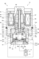
- FIG. 1 is a cross-sectional view showing a fluid control valve of Example 1 according to the present invention
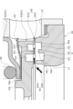
- FIG. 4 is an enlarged cross-sectional view showing a state in which the outer seal portion is closed and the inner seal portion is substantially closed in the fluid control valve of Embodiment 1
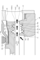
- FIG. 4 is an enlarged cross-sectional view showing the state of the fluid control valve of Example 1 at the initial stage of valve opening or final stage of valve closing when the leaf spring is compressed to open the outer seal portion and the inner seal portion
- FIG. 4 is an enlarged cross-sectional view showing a state in which the coil spring and the leaf spring are compressed to fully open the outer seal portion and the inner seal portion in the fluid control valve of the first embodiment
- FIG. 8 is an enlarged cross-sectional view showing a state in which the coil spring and the leaf spring are compressed to fully open the outer seal portion and the inner seal portion in the fluid control valve of the second embodiment according to the present invention
- FIG. 11 is an enlarged cross-sectional view showing a state in which the coil spring and the plate spring are compressed to fully open the outer seal portion and the inner seal portion in the fluid control valve of Example 3 according to the present invention
- FIG. 1 A fluid control valve according to Embodiment 1 will be described with reference to FIGS. 1 to 5.
- FIG. a fluid control valve used for a shock absorber will be described as an example, but it can also be applied to other uses.
- the top and bottom of the fluid control valve will be described as viewed from the front in FIG.
- the lower side of the paper where the outer seal portion 60 and the inner seal portion 70 are arranged is the lower side of the fluid control valve
- the upper side of the paper where the solenoid 80 as the drive source is arranged is the upper side of the fluid control valve.
- the outer seal portion 60 is a main valve of the fluid control valve V1
- the inner seal portion 70 is a sub-valve that assists the sealing function of the main valve.
- the fluid control valve V1 of the present invention is fluidly connected to the absorber piston chamber P and the reservoir chamber R of the shock absorber A.
- the fluid control valve V1 opens the outer seal portion 60 and the inner seal portion 70 to allow the working fluid to flow from the discharge passage 12 to the reservoir chamber R. let it flow. Thereby, the fluid control valve V1 controls the flow rate of the working fluid flowing from the absorber piston chamber P toward the reservoir chamber R.
- the fluid control characteristics of the outer seal portion 60 and the inner seal portion 70 are adjusted by the pilot valve 50.
- the fluid control valve V1 controls the damping force of the shock absorber A.
- the fluid control valve V1 is mainly composed of a valve housing 10, a pilot valve 50, an outer seal portion 60, an inner seal portion 70, and a solenoid 80.
- An annular space H which will be described later, is formed between the outer seal portion 60 and the inner seal portion 70 in the fluid control valve V1.
- the pilot valve 50 is arranged at the upper end within the valve housing 10 . Further, the outer seal portion 60 and the inner seal portion 70 are arranged below the pilot valve 50 within the valve housing 10 .
- the pilot valve 50 is composed of a pilot valve body 51 and a pilot valve seat 40a.
- the pilot valve 50 is opened and closed by bringing the lower end portion 51a of the pilot valve body 51 into and out of contact with the pilot valve seat 40a.
- the outer seal portion 60 is composed of a main valve body 61 as a valve body and an outer diameter side valve seat 45a.
- the outer seal portion 60 is opened and closed by bringing the outer diameter side lower end portion 61a of the main valve body 61 into and out of contact with the outer diameter side valve seat 45a.
- the inner seal portion 70 is composed of the main valve body 61 and the inner diameter side valve seat 45b.
- the inner seal portion 70 opens and closes when the inner diameter side lower end portion 61b of the main valve body 61 contacts and separates from the inner diameter side valve seat 45b.
- the outer seal portion 60 blocks the space between the outer diameter side lower end portion 61a of the main valve body 61 and the outer diameter side valve seat 45a in the valve closed state.
- the inner seal portion 70 When the inner seal portion 70 is closed, a minute gap is formed between the inner diameter side lower end portion 61b of the main valve body 61 and the inner diameter side valve seat 45b. That is, the inner seal portion 70 functions as an orifice.
- the space H formed between the outer seal portion 60 and the inner seal portion 70 is filled with working fluid from the inflow passage 11 through the inner seal portion 70 even when the outer seal portion 60 and the inner seal portion 70 are closed. flows in, and the state in which the space H is filled with the working fluid is easily maintained.
- a solenoid 80 is connected to the valve housing 10 and applies a driving force to the pilot valve body 51 .
- the solenoid 80 is mainly composed of a casing 81, a center post 82, a rod 83, a movable iron core 84, a coil spring 85, a coil 86, a sleeve 87 and a bearing 88. It is configured.
- the casing 81 has a stepped cylindrical body portion 81a into which the center post 82 is fitted and fixed from below in the axial direction.
- the casing 81 is formed with an opening 81b that is continuous with the lower end of the main body 81a and opens downward.
- the center post 82 is formed in a stepped cylindrical shape from a rigid body made of a magnetic material such as iron or silicon steel.
- the center post 82 has a cylindrical body portion 82a extending in the axial direction.
- center post 82 is formed with an opening 82b that is continuous with the lower end of the main body portion 82a and opens downward from the center post 82. As shown in FIG.
- the rod 83 is cylindrically formed.
- the rod 83 is inserted through the center post 82 and arranged to reciprocate in the axial direction.
- the rod 83 is inserted into and fixed to the movable iron core 84 . Accordingly, when the solenoid 80 is energized, the rod 83 is moved following the movable iron core 84 that moves in the valve closing direction. Accordingly, the rod 83 moves the pilot valve body 51 in the valve closing direction, that is, downward in the axial direction.
- the rod 83 has an upper end inserted through the bearing 88 and a lower end inserted through a guide portion 82 c formed on the inner peripheral surface of the center post 82 .
- the axial movement of the rod 83 is guided by the bearing 88 and the guide portion 82c. Therefore, the rod 83 is less likely to tilt in the radial direction when moving in the axial direction.
- the coil spring 85 is arranged between the pilot valve seat member 40 and the pilot valve body 51 .
- the coil spring 85 biases the pilot valve body 51 upward in the valve opening direction of the pilot valve 50, that is, in the axial direction.
- a coil 86 is an excitation coil wound around the outside of the center post 82 via a bobbin.
- the sleeve 87 is formed in a cylindrical shape with a bottom.
- a bearing 88 that guides the movement of the rod 83 is fitted and fixed to the sleeve 87 .
- valve housing 10 side Elements on the valve housing 10 side are the valve housing 10 , the pilot valve 50 , the outer seal portion 60 and the inner seal portion 70 .
- valve housing 10 is formed in a cylindrical shape with an inner step made of metal material or resin material.
- the valve housing 10 is formed with a cylindrical portion 10a, a small-diameter bottomed cylindrical portion 10b, a medium-diameter bottomed cylindrical portion 10c, and a large-diameter bottomed cylindrical portion 10d in order from the top in the axial direction.
- a pilot valve body 51 is inserted into the cylindrical portion 10a from above in the axial direction.
- the pilot valve body 51 is formed in a T-shape in cross section having a cylindrical portion 51b and a flange portion 51c.
- the cylindrical portion 51b has a cylindrical shape extending in the axial direction. A lower end portion 51a of the cylindrical portion 51b is seated on the pilot valve seat 40a.
- the lower end surface of the rod 83 is in contact with the upper end portion of the cylindrical portion 51b.
- the pilot valve body 51 that receives the biasing force of the coil spring 85 is pressed against the rod 83 .
- the flange portion 51c is disk-shaped and extends radially outward from the upper end portion of the cylindrical portion 51b.
- a communication passage 51d is formed through the flange portion 51c in the axial direction.
- the communication passage 51d communicates the cylindrical portion 10a of the valve housing 10 with the opening 82b of the center post 82. As shown in FIG.
- the outer peripheral surface of the flange portion 51c is formed so as to be movable while being in sliding contact with the inner peripheral surface of the cylindrical portion 10a of the valve housing 10. As a result, the cylindrical portion 10a can guide the movement of the pilot valve body 51. As shown in FIG.
- the small-diameter bottomed cylindrical portion 10b is continuous with the cylindrical portion 10a, and is recessed upward in the axial direction with a larger diameter inside than the cylindrical portion 10a.
- a pilot valve seat member 40 press-fitted from below in the axial direction is integrally fixed to the small-diameter bottomed cylindrical portion 10b in a substantially sealed state.
- the pilot valve seat member 40 is made of a metal material or a resin material and is formed in a circular plate shape having a communicating passage 40b passing therethrough in the axial direction.
- annular projection 40c that protrudes axially upward is formed at the center of the upper end of the pilot valve seat member 40 .
- the upper end of the annular projection 40c is the pilot valve seat 40a.
- the medium-diameter bottomed cylindrical portion 10c is continuous with the small-diameter bottomed cylindrical portion 10b, and is recessed upward in the axial direction with an inner diameter larger than the small-diameter bottomed cylindrical portion 10b.
- a main valve body 61 and a coil spring 64 are inserted from below in the axial direction into the medium-diameter bottomed cylindrical portion 10c.
- An upper end portion of a main valve seat member 45 as a valve seat member press-fitted from below in the axial direction is integrally fixed to the medium-diameter bottomed cylindrical portion 10c in a substantially sealed state.
- a pilot control chamber S is formed in the space inside the small-diameter bottomed cylindrical portion 10b and the medium-diameter bottomed cylindrical portion 10c of the valve housing 10.
- the pilot control chamber S is defined by a small-diameter bottomed cylindrical portion 10 b , an intermediate-diameter bottomed cylindrical portion 10 c , a pilot valve seat member 40 , a pilot valve body 51 and a main valve body 61 .
- the main valve body 61 is composed of a guide member 62 formed in a substantially U-shaped cylindrical shape in cross section, and a seal member 63 . That is, the main valve body 61 is divided into two in the axial direction by the guide member 62 and the seal member 63 .
- the guide member 62 has a cylindrical portion 62a extending in the axial direction, and a bottom portion 62b extending radially inwardly from the lower end of the cylindrical portion 62a. ing.
- a coil spring 64 that biases the main valve body 61 in the valve closing direction is arranged between the bottom portion 62b of the guide member 62 and the pilot valve seat member 40 in a compressed state. Specifically, the lower end of the coil spring 64 is inserted inside the guide member 62 .
- a leaf spring 65 is arranged between the guide member 62 and the seal member 63 to bias the seal member 63 in the valve closing direction.
- the outer peripheral surface of the cylindrical portion 62a of the guide member 62 is formed so as to be movable while slidingly contacting the inner peripheral surface of the medium-diameter bottomed cylindrical portion 10c of the valve housing 10.
- the medium-diameter bottomed cylindrical portion 10 c can guide the movement of the main valve body 61 .
- the sealing member 63 includes an annular outer diameter side protrusion 63a that protrudes axially upward from the outer diameter side end, and an annular inner diameter side protrusion 63a that protrudes axially upward from the radial center portion.
- a convex portion 63b is provided, and an annular concave portion 63c is formed between the outer diameter side convex portion 63a and the inner diameter side convex portion 63b.
- the inner diameter side protrusion 63 b is inserted into the through hole 62 c of the guide member 62 .
- a communicating passage 63d is formed through the seal member 63 in the radial direction.
- the interior of the main valve body 61 communicates with the inflow passage 11 through the communication passage 63 d of the seal member 63 .
- an outer diameter side lower end portion 61a of the main valve body 61 is formed on the outer diameter side
- an inner diameter side lower end portion 61b of the main valve body 61 is formed on the inner diameter side.
- the outer diameter side lower end portion 61a is seated on the outer diameter side valve seat 45a when the outer seal portion 60 is closed
- the inner diameter side lower end portion 61b is close to the inner diameter side valve seat 45b when the inner seal portion 70 is closed. do.
- the outer diameter side lower end portion 61a and the inner diameter side lower end portion 61b are formed of annular protrusions that protrude downward in the axial direction.
- an annular protrusion 61c is formed that protrudes axially downward between the outer diameter side lower end 61a and the inner diameter side lower end 61b in the radial direction.
- the lower end surface of the convex portion 61c is formed on substantially the same plane as the lower end surfaces of the outer diameter side lower end portion 61a and the inner diameter side lower end portion 61b. That is, the lower end surface of the convex portion 61c is formed so as not to protrude toward the main valve seat member 45 from the lower end surfaces of the outer diameter side lower end portion 61a and the inner diameter side lower end portion 61b.
- the lower end surface of the convex portion 61c may be located above the lower end surfaces of the outer diameter side lower end portion 61a and the inner diameter side lower end portion 61b.
- the convex portion 61c is formed to have a rectangular cross section.
- annular recess 61d recessed axially upward between the outer diameter side lower end 61a and the projection 61c, and an axially extending recess between the inner diameter side lower end 61b and the projection 61c.
- An annular recess 61e recessed upward is formed.
- the annular recess 61e on the inner diameter side is formed to have a greater depth and recess amount than the annular recess 61d on the outer diameter side.
- the leaf spring 65 has a stepped circular ring and plate shape in cross section, and has a spring constant lower than that of the coil spring 64 .
- the plate spring 65 has an inner diameter plate portion 65 a that contacts the lower end surface of the bottom portion 62 b of the guide member 62 , and an outer diameter plate portion 65 b that contacts the upper end surface of the outer diameter side convex portion 63 a of the seal member 63 . is arranged in contact with the
- the large-diameter bottomed cylindrical portion 10d is continuous with the medium-diameter bottomed cylindrical portion 10c, and is recessed upward in the axial direction by expanding the inner diameter of the medium-diameter bottomed cylindrical portion 10c.
- a main valve seat member 45 press-fitted from below in the axial direction is integrally fixed to the large-diameter bottomed cylindrical portion 10d in a substantially sealed state.
- the main valve seat member 45 is made of a metal material or a resin material and is formed in a cylindrical shape having an inflow passage 11 extending therethrough in the axial direction.
- the main valve seat member 45 is press-fitted and fixed to the large-diameter bottomed cylindrical portion 10d from below in the axial direction through a gasket in a sealed state.
- annular outer diameter side valve seat 45a is formed on the outer diameter side
- annular inner diameter side valve seat 45b is formed on the inner diameter side
- an annular protrusion 45c is formed between the outer diameter side valve seat 45a and the inner diameter side valve seat 45b in the radial direction.
- the upper end surface of the convex portion 45c is formed so as not to protrude toward the main valve body 61 from the outer diameter side valve seat 45a and the inner diameter side valve seat 45b. That is, the upper end surface of the convex portion 45c is positioned below the outer diameter side valve seat 45a and the inner diameter side valve seat 45b.
- the convex portion 45c is formed to have a rectangular cross section.
- annular recess 45d recessed axially downward between the outer diameter side valve seat 45a and the protrusion 45c and between the inner diameter side valve seat 45b and the protrusion 45c
- An annular recess 45e recessed downward in the axial direction is formed.
- the annular recess 45e on the inner diameter side is formed to have a greater depth and depth than the annular recess 45d on the outer diameter side.
- the fluid control valve V1 has an annular recess formed between the outer seal portion 60 and the inner seal portion 70 by the annular recesses 61d and 61e of the main valve body 61 and the annular recesses 45d and 45e of the main valve seat member 45.
- a space H is formed.
- a protrusion 61 c linearly protrudes axially downward from the main valve body 61
- a protruding portion 45 c linearly protrudes axially upward from the main valve seat member 45 .
- the convex portion 61c projecting linearly downward in the axial direction from the main valve body 61 and the convex portion 45c projecting linearly upward in the axial direction from the main valve seat member 45 are arranged in the axial direction.
- the convex portion 61c and the convex portion 45c facing each other are separated from each other in the axial direction.
- an annular space H1 is formed by the annular recess 61e and the annular recess 45e on the inner diameter side of the protrusions 61c and 45c.
- an annular space H2 is formed by the annular recess 61d and the annular recess 45d on the outer diameter side of the projections 61c and 45c.
- the space H1 is formed larger than the space H2.
- a space H3, which is an annular gap is formed between the convex portion 61c and the convex portion 45c that are spaced apart in the axial direction.
- the space H3 communicates the spaces H1 and H2.
- the space H is divided into three by the projections, but the space H may be divided into four or more by increasing the number of projections.
- a communication groove 10e having a downward L-shaped cross section is formed from the upper end to the side surface of the cylindrical portion 10a.
- the lower end of the communication groove 10e is positioned below the opening 81b of the casing 81 and is open radially outward.
- the communication groove 10 e constitutes the pilot side discharge passage 13 of the pilot valve 50 .
- the pilot-side discharge passage 13 includes the cylindrical portion 10a, the small-diameter bottomed cylindrical portion 10b, the communication groove 10e, the annular projection 40c of the pilot valve seat member 40, the opening 81b of the casing 81, and the center post. 82 by an opening 82b.
- valve housing 10 is formed with a discharge passage 12 that extends radially outward from the medium-diameter bottomed cylindrical portion 10c and communicates the inner side of the medium-diameter bottomed cylindrical portion 10c with the reservoir chamber R.
- FIG. 1 mainly the opening and closing operations of the pilot valve 50, the outer seal portion 60 and the inner seal portion 70 will be described with reference to FIGS. 1 to 4.
- FIG. 1 mainly the opening and closing operations of the pilot valve 50, the outer seal portion 60 and the inner seal portion 70 will be described with reference to FIGS. 1 to 4.
- FIG. 1 mainly the opening and closing operations of the pilot valve 50, the outer seal portion 60 and the inner seal portion 70 will be described with reference to FIGS. 1 to 4.
- the fluid control valve V1 in the de-energized state will be described.
- the pilot valve body 51 of the pilot valve 50 in the non-energized state, the pilot valve body 51 of the pilot valve 50 is pressed upward in the axial direction by the biasing force of the coil spring 85 .
- the pilot valve body 51 is separated from the pilot valve seat 40a, and the pilot valve 50 is opened.
- the pilot valve opening degree at this time is the maximum in this embodiment.
- the working fluid passes through the communication passage 63d in the main valve body 61 and the pilot control chamber S, and flows through the pilot side discharge passage 13. flows into the reservoir chamber R from the Along with this, the working fluid may also flow into the reservoir chamber R from the discharge passage 12 depending on the pressure of the working fluid, as will be described below.
- the cross-sectional area of the communication passage 63d in the main valve body 61 is formed to be narrow. Therefore, even if the pressure of the working fluid in the inflow passage 11 increases, the pressure of the working fluid in the pilot control chamber S is less likely to increase in response to the pressure of the working fluid in the inflow passage 11 . Therefore, a differential pressure is generated between the pressure of the working fluid in the inflow passage 11 and the pressure of the working fluid in the pilot control chamber S. As the differential pressure increases, the outer seal portion 60 and the inner seal portion 70 are more easily opened.
- pressure Pin in the inflow path 11 the pressure of the working fluid in the pilot control chamber S is referred to as "pressure Ps in the pilot control chamber S”.
- the reason why the differential pressure ⁇ P decreases is that the working fluid flows from the discharge passage 12 into the reservoir chamber R through the inner seal portion 70, the space H, and the outer seal portion 60, and the pressure Pin in the inflow passage 11 decreases.
- the working fluid flows into the pilot control chamber S from the passage 63d, and the pressure Pin in the inflow passage 11 decreases. be.
- the opening and closing operations of the outer seal portion 60 and the inner seal portion 70 will be described in more detail with specific examples.
- the force of the coil spring 64 urging the guide member 62 downward is greater than the force of the leaf spring 65 urging the guide member 62 upward.
- the inner diameter plate portion 65a of the plate spring 65 and the bottom surface of the annular concave portion 63c of the seal member 63 are spaced apart in the axial direction, which serves as a movement allowance for the seal member 63 in the axial direction.
- the outer diameter side lower end portion 61a of the main valve body 61 formed at the lower end portion of the seal member 63 is slightly separated from the outer diameter side valve seat 45a, and the inner diameter side lower end portion 61b of the main valve body 61 is positioned at the inner diameter side. Further away from the valve seat 45b, the outer seal portion 60 and the inner seal portion 70 are opened. As a result, the working fluid flows from the discharge passage 12 into the reservoir chamber R through the inner seal portion 70, the space H, and the outer seal portion 60 (see solid line arrows in FIG. 3).
- the space H3 which is an annular gap formed between the convex portion 61c and the convex portion 45c that are spaced apart in the axial direction, functions as a diaphragm.
- the fluid pressure of the working fluid that is applied tends to be small.
- the inner diameter side space H1 formed by the annular recess 61e and the annular recess 45e is larger than the outer diameter side space H2 formed by the annular recess 61d and the annular recess 45d, the working fluid passing through the space H The pressure tends to decrease step by step.
- the outer diameter side lower end portion 61a of the main valve body 61 is largely separated from the outer diameter side valve seat 45a, and the inner diameter side lower end portion 61b of the main valve body 61 is largely separated from the inner diameter side valve seat 45b.
- 60 and inner seal 70 are opened.
- the working fluid flows into the reservoir chamber R from the discharge passage 12 through the inner seal portion 70, the space H, and the outer seal portion 60 (see solid line arrows in FIG. 4).
- valve opening degrees of the outer seal portion 60 and the inner seal portion 70 are maximized when the pressure Pin in the inflow passage 11 is greater than or equal to the large P3 (Pin ⁇ P3).
- the space H is divided into a space H1 on the inner diameter side and a space H2 on the outer diameter side across a space H3, which is an annular gap formed between the convex portion 61c and the convex portion 45c. and the space H2 can stabilize the flow of the working fluid.
- the space H is an annular gap formed between the convex portion 61c and the convex portion 45c spaced apart in the axial direction. Since H3 becomes larger, the space H3 no longer functions as a diaphragm. As a result, the flow rate of the working fluid discharged from the inflow passage 11 to the discharge passage 12 through the inner seal portion 70 , the space H, and the outer seal portion 60 can be easily ensured.
- the working fluid that becomes surplus in the pilot control chamber S flows into the reservoir chamber R from the pilot side discharge passage 13 .
- the main valve When the working fluid flows from the discharge passage 12 into the reservoir chamber R through the inner seal portion 70, the space H, and the outer seal portion 60, and the pressure Pin in the inflow passage 11 becomes less than the small P1 (Pin ⁇ P1), the main valve
- the outer diameter side lower end portion 61a of the body 61 is seated on the outer diameter side valve seat 45a, the inner diameter side lower end portion 61b of the main valve body 61 is closest to the inner diameter side valve seat 45b, the outer seal portion 60 is closed, and
- the inner seal portion 70 is substantially closed.
- the rod 83 fixed to the movable iron core 84 moves downward in the axial direction together with the pilot valve body 51 .
- the pilot valve 50 is closed when the pilot valve opening degree is reduced and a current exceeding a predetermined level is applied.
- the working fluid in the inflow passage 11 flows from the pilot side discharge passage 13 as the shock absorber A operates, as in the non-energized state. It flows into the reservoir chamber R. Further, as described above, the working fluid also flows into the reservoir chamber R from the discharge passage 12 depending on the pressure Pin in the inflow passage 11 .
- the damping force of the shock absorber A is minimum. That is, the damping force is controlled to be the smallest when the fluid control valve V1 is in the non-energized state.
- the smaller the opening degree of the pilot valve 50 the smaller the differential pressure ⁇ P in a short time. That is, the opening time of the outer seal portion 60 and the inner seal portion 70 is shortened as the pilot valve opening degree of the pilot valve 50 becomes smaller.
- the fluid control characteristics of the outer seal portion 60 and the inner seal portion 70 are controlled according to the pilot valve opening degree of the pilot valve 50 .
- the fluid control valve V1 can variably control the damping force of the shock absorber A.
- the fluid control valve V1 when the pilot valve 50 is closed in the energized state, the fluid control valve V1 is in a state in which the working fluid is most difficult to pass through the pilot valve 50, and the outer seal portion 60 and the inner seal portion 70 are open. It is in a state where it is difficult to Therefore, the fluid control valve V1 can maximize the damping force in the shock absorber A.
- the current value energized to the coil 86 constituting the solenoid 80 is set based on input parameters such as vehicle speed, vehicle acceleration/deceleration, steering angle, road surface condition, and sprung load.
- pilot valve 50 in the open state may be closed by setting a current value greater than or equal to a predetermined value.
- the space H is formed between the outer seal portion 60 and the inner seal portion 70, so that the initial valve opening or the closed valve when the valve opening degree is small is controlled.
- the pressure of the working fluid discharged from the inflow passage 11 to the discharge passage 12 through the inner seal portion 70, the space H, and the outer seal portion 60 can be reduced to smoothly change the fluid control characteristics. can.
- FIG. 4 when the valve opening degree of the outer seal portion 60 and the inner seal portion 70 is large, the formation of turbulent flow in the space H is prevented by the convex portion 61 c and the convex portion 45 c projecting into the space H.
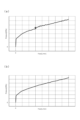
- FIG. 5 is a diagram showing the results of measuring the fluid control characteristics of the conventional fluid control valve and the fluid control valve V1 of the present embodiment under the same conditions such as the current value.
- the convex portion 61c and the convex portion 45c are separated from the opposed members, that is, the main valve body 61 and the main valve seat member 45.
- the space H3 which is the gap between the convex portion 61c and the convex portion 45c facing each other, is actuated at the initial stage of valve opening or the final stage of valve closing when the valve opening degree of the outer seal portion 60 and the inner seal portion 70 is small. Fluid can pass through. Further, even when the valve opening degrees of the outer seal portion 60 and the inner seal portion 70 are large, the flow rate of the working fluid passing through the space H3 is easily ensured.
- the convex portion 61c and the convex portion 45c are provided on both the main valve body 61 and the main valve seat member 45, it is possible to prevent the working fluid from forming a vortex in the space H.
- the space H is divided into an inner space H1 and an outer space H2 with the convex portion 61c and the convex portion 45c interposed therebetween. It is easy to adjust the characteristics step by step.
- the convex portion 61c and the convex portion 45c are formed in an annular shape, the flow rate of the working fluid passing through the space H3, which is the gap between the convex portion 61c and the convex portion 45c facing each other, is made uniform. Therefore, the fluid control characteristics can be stabilized.
- the spaces H1 and H2 are annularly formed by the annular recesses 61d and 61e of the main valve body 61 and the annular recesses 45d and 45e of the main valve seat member 45. can be made uniform, the fluid control characteristics can be further stabilized.
- the lower end face of the convex portion 61c of the main valve body 61 is arranged axially closer to the seal portions of the outer seal portion 60 and the inner seal portion 70 than the convex portion 45c of the main valve seat member 45 facing it.
- the outer diameter side lower end portion 61a of the main valve body 261 is provided on the outer diameter side at the lower end portion of the seal member 263 that constitutes the main valve body 261.
- the inner diameter side lower end portion 61b of the main valve body 261 is formed on the inner diameter side.
- annular protrusion 261c is formed between the outer diameter side lower end portion 61a and the inner diameter side lower end portion 61b to protrude downward in the axial direction.
- the lower end surface of the projection 261c is formed so as not to protrude toward the main valve seat member 245 from the lower end surfaces of the outer diameter side lower end portion 61a and the inner diameter side lower end portion 61b. That is, the lower end surface of the convex portion 261c is located above the lower end surfaces of the outer diameter side lower end portion 61a and the inner diameter side lower end portion 61b.
- the upper end of the main valve seat member 245 is formed with an annular recess 245c between the outer diameter side valve seat 45a and the inner diameter side valve seat 45b.
- the fluid control valve V2 has an annular space H formed between the outer seal portion 60 and the inner seal portion 70 by the annular recesses 61d and 61e of the main valve body 261 and the annular recess 245c of the main valve seat member 245. is formed. Further, in the space H, a convex portion 261c protrudes linearly downward from the main valve body 261 in the axial direction.
- convex portion 261c projecting linearly downward in the axial direction from the main valve body 261 and the bottom surface of the annular concave portion 245c of the main valve seat member 245 face each other in the axial direction.
- convex portion 261c is axially spaced apart from the bottom surface of annular concave portion 245c, which is a facing portion (not shown).
- an annular space H21 is formed by the inner diameter portions of the annular recess 61e and the annular recess 245c on the inner diameter side of the protrusion 261c.
- an annular space H22 is formed by the outer diameter portions of the annular recess 61d and the annular recess 245c on the outer diameter side of the protrusion 261c.
- the space H21 is formed larger than the space H22.
- a space H23 which is an annular gap, is formed between the convex portion 261c and the bottom surface of the annular concave portion 245c, which are spaced apart in the axial direction. The space H23 communicates the spaces H21 and H22.
- the main valve seat member 245 can easily form the space H between the outer seal portion 60 and the inner seal portion 70 by forming only one annular concave portion 245c in the main valve body 261. be able to.
- the outer seal portion 60 and the inner seal portion 70 are closed.
- the lower end of the projection 261c may be configured to enter the annular recess.
- the uneven configurations of the main valve body 261 and the main valve seat member 245 may be reversed.
- the space H may be formed by forming only one annular concave portion in the main valve body and forming a convex portion or an annular concave portion in the main valve seat member.
- the fluid control valve V3 of the third embodiment includes a main valve body 261 having a seal member 263 having substantially the same configuration as that of the second embodiment.
- annular protrusion 345c is formed between the outer diameter side valve seat 45a and the inner diameter side valve seat 45b and protrudes axially upward.
- annular recess 345d recessed axially downward between the outer diameter side valve seat 45a and the protrusion 345c and between the inner diameter side valve seat 45b and the protrusion 345c
- An annular recess 345e recessed downward in the axial direction is formed.
- the annular recesses 345d and 345e on the inner diameter side are formed to have the same depth.
- the fluid control valve V3 has an annular recess formed between the outer seal portion 60 and the inner seal portion 70 by the annular recesses 61d and 61e of the main valve body 261 and the annular recesses 345d and 345e of the main valve seat member 245.
- a space H is formed.
- a projection 261 c linearly projects axially downward from the main valve body 261
- a projection 345 c linearly projects axially upward from the main valve seat member 345 .
- the convex portion 261c projecting linearly downward in the axial direction from the main valve body 261 and the bottom surface of the annular concave portion 345d on the outer diameter side of the convex portion 345c of the main valve seat member 345 extend axially.
- the convex portion 261c is axially separated from the bottom surface of the annular concave portion 345d.
- the projection 345c projecting linearly upward in the axial direction from the main valve seat member 345 and the bottom surface of the annular recess 61e of the main valve body 261 face each other in the axial direction.
- the protrusion 345c is axially separated from the bottom surface of the annular recess 61e.
- the space H can be divided into a plurality of small spaces because the projection 261c of the main valve body 261 projecting into the space H and the projection 345c of the main valve seat member 345 are out of phase in the radial direction. Therefore, formation of a vortex by the working fluid in the space H can be inhibited.
- the fluid control valve has been described as having a pilot valve and a main valve, but this is not limiting and the fluid control valve may have only a main valve.
- the inflow path and the discharge path in the housing have been described as a structure through which the working fluid flows. may flow into the interior of the housing. That is, the working fluid is not limited to direct flow, and the inflow path and the discharge path may be configured to flow the working fluid inside or to discharge the working fluid to the outside.
- the outer diameter side valve seat and the inner diameter side valve seat are formed on the main valve seat member separate from the valve housing.
- the valve seat may be integrally formed with the valve housing.
- the projections projecting from the main valve body or the main valve seat member are configured to have a rectangular cross-section. It may be formed to have a substantially semicircular cross section. According to this, since the tapered surface or the curved surface that is inclined along the working fluid flowing in the space is formed on the convex portion, the flow of the working fluid can be guided, so that the working fluid generates a large eddy current in the space. can be suppressed.
- the convex portion protruding from the main valve body or the main valve seat member has been described as being separated from the facing member when the outer seal portion and the inner seal portion are closed.
- the member facing the convex portion may be separated from the member facing at least at the beginning of valve opening or the end of valve closing when the valve opening degree of the outer seal portion and the inner seal portion is small. In the valve closed state of the seal portion, a member facing the convex portion may be in contact with the convex portion.
- the convex portion projecting linearly from the main valve body or the main valve seat member has been described as having a projecting direction perpendicular to the flow direction of the working fluid in the space.
- the projecting direction of the convex portion may be a direction that is inclined along the working fluid flowing through the space.
- the projections are not limited to straight projections, and may be arc-shaped or step-shaped projections.
- the convex portion protruding from the main valve body or the main valve seat member has been described as having an annular configuration. In this case, it is preferable that the plurality of protrusions are evenly distributed in the circumferential direction.
- the convex portion protruding from the main valve body or the main valve seat member has been described as being integrally formed with the main valve body or the main valve seat member.
- the outer seal portion and the inner seal portion of the main valve body or the main valve seat member may be configured by a separate member.
Landscapes
- Engineering & Computer Science (AREA)
- General Engineering & Computer Science (AREA)
- Mechanical Engineering (AREA)
- Fluid-Driven Valves (AREA)
- Safety Valves (AREA)
Abstract
Description
流入路および排出路を有するバルブハウジングと、前記流入路および前記排出路の間に配置された弁座部材と、前記弁座部材と離接可能に配置され、前記弁座部材とともに内シール部と外シール部を形成する弁体と、を具備する流体制御弁であって、
前記内シール部と前記外シール部の間に形成された空間に凸部が張り出している。
これによれば、内シール部と外シール部との間に空間が形成されていることにより、弁開度が小さい開弁初期または閉弁終期における流体制御特性を滑らかに変化させることができる。また、弁開度が大きい状態では、空間に張り出す凸部により、空間における乱流形成を抑制することができるため、弁開度を安定させ、流体制御特性を安定させることができる。
これによれば、弁開度が小さい開弁初期または閉弁終期において、凸部と対向する部材である弁体または弁座部材との間を流体が通過可能となっている。また、弁開度が大きい状態においても凸部と対向する部材との間を通過する流体の流量が確保されやすい。
これによれば、空間における流体による渦流の形成を阻害することができる。
これによれば、空間は凸部を挟んで内外に分けられるため、流体制御特性を段階的に調整しやすい。
これによれば、凸部と対向する部材との間を通過する流体の流量を均一にすることができるため、流体制御特性をより安定させることができる。
11 流入路
12 排出路
13 パイロット側排出路
40 パイロット弁座部材
45 主弁座部材(弁座部材,対向する部材)
45a 外径側弁座
45b 内径側弁座
45c 凸部
45d,45e 環状凹部
50 パイロット弁
51 パイロット弁体
60 外シール部
61 主弁体(弁体,対向する部材)
61a 外径側下端部
61b 内径側下端部
61c 凸部
61d,61e 環状凹部
62 ガイド部材
63 シール部材
64 コイルスプリング
65 板バネ
70 内シール部
H 空間
V1~V3 流体制御弁
Claims (5)
- 流入路および排出路を有するバルブハウジングと、前記流入路および前記排出路の間に配置された弁座部材と、前記弁座部材と離接可能に配置され、前記弁座部材とともに内シール部および外シール部を形成する弁体と、を具備する流体制御弁であって、
前記内シール部と前記外シール部の間に形成された空間に凸部が張り出している流体制御弁。 - 前記凸部は、閉弁時において、対向する部材から離間している請求項1に記載の流体制御弁。
- 前記凸部は、前記弁体と前記弁座部材の両方に設けられている請求項2に記載の流体制御弁。
- 前記凸部同士が対向している請求項3に記載の流体制御弁。
- 前記凸部は、環状に形成されている請求項1ないし4のいずれかに記載の流体制御弁。
Priority Applications (2)
| Application Number | Priority Date | Filing Date | Title |
|---|---|---|---|
| JP2023545696A JPWO2023033143A1 (ja) | 2021-09-02 | 2022-09-02 | |
| CN202280058650.4A CN117881912A (zh) | 2021-09-02 | 2022-09-02 | 流体控制阀 |
Applications Claiming Priority (2)
| Application Number | Priority Date | Filing Date | Title |
|---|---|---|---|
| JP2021143492 | 2021-09-02 | ||
| JP2021-143492 | 2021-09-02 |
Publications (1)
| Publication Number | Publication Date |
|---|---|
| WO2023033143A1 true WO2023033143A1 (ja) | 2023-03-09 |
Family
ID=85412422
Family Applications (1)
| Application Number | Title | Priority Date | Filing Date |
|---|---|---|---|
| PCT/JP2022/033101 WO2023033143A1 (ja) | 2021-09-02 | 2022-09-02 | 流体制御弁 |
Country Status (3)
| Country | Link |
|---|---|
| JP (1) | JPWO2023033143A1 (ja) |
| CN (1) | CN117881912A (ja) |
| WO (1) | WO2023033143A1 (ja) |
Citations (5)
| Publication number | Priority date | Publication date | Assignee | Title |
|---|---|---|---|---|
| JPH04106576U (ja) * | 1991-02-28 | 1992-09-14 | エヌオーケー株式会社 | ソレノイドバルブ |
| JP2010270900A (ja) * | 2009-05-25 | 2010-12-02 | Mitsubishi Heavy Ind Ltd | 弁装置 |
| JP2011501798A (ja) | 2007-10-17 | 2011-01-13 | オーリンス・レイシング・エービー | ばね機構を有する緩衝バルブ |
| JP2015152069A (ja) * | 2014-02-13 | 2015-08-24 | 富士重工業株式会社 | 流量制御弁 |
| JP2020008038A (ja) * | 2018-07-04 | 2020-01-16 | 北越工業株式会社 | 気体制御弁 |
-
2022
- 2022-09-02 WO PCT/JP2022/033101 patent/WO2023033143A1/ja active Application Filing
- 2022-09-02 JP JP2023545696A patent/JPWO2023033143A1/ja active Pending
- 2022-09-02 CN CN202280058650.4A patent/CN117881912A/zh active Pending
Patent Citations (5)
| Publication number | Priority date | Publication date | Assignee | Title |
|---|---|---|---|---|
| JPH04106576U (ja) * | 1991-02-28 | 1992-09-14 | エヌオーケー株式会社 | ソレノイドバルブ |
| JP2011501798A (ja) | 2007-10-17 | 2011-01-13 | オーリンス・レイシング・エービー | ばね機構を有する緩衝バルブ |
| JP2010270900A (ja) * | 2009-05-25 | 2010-12-02 | Mitsubishi Heavy Ind Ltd | 弁装置 |
| JP2015152069A (ja) * | 2014-02-13 | 2015-08-24 | 富士重工業株式会社 | 流量制御弁 |
| JP2020008038A (ja) * | 2018-07-04 | 2020-01-16 | 北越工業株式会社 | 気体制御弁 |
Also Published As
| Publication number | Publication date |
|---|---|
| CN117881912A (zh) | 2024-04-12 |
| JPWO2023033143A1 (ja) | 2023-03-09 |
Similar Documents
| Publication | Publication Date | Title |
|---|---|---|
| EP2103835B1 (en) | Damping valve | |
| EP3835578B1 (en) | Capacity control valve | |
| US7946399B2 (en) | Hydraulic shock absorber | |
| JPWO2011052371A1 (ja) | ソレノイドバルブ | |
| JP5773075B2 (ja) | 常閉型電磁弁 | |
| US4971114A (en) | Electromagnetic proportional pressure control valve | |
| WO2015104923A1 (ja) | ソレノイドバルブ | |
| EP3822484A1 (en) | Capacity control valve | |
| WO2023033143A1 (ja) | 流体制御弁 | |
| EP4148274B1 (en) | Capacity control valve | |
| JP7467427B2 (ja) | 容量制御弁 | |
| US20230375066A1 (en) | Valve | |
| WO2022071092A1 (ja) | 流体制御弁 | |
| JP7289603B2 (ja) | 容量制御弁 | |
| JP7438643B2 (ja) | 容量制御弁 | |
| WO2022255188A1 (ja) | 流体制御弁 | |
| JP7289604B2 (ja) | 容量制御弁 | |
| JP2013210049A (ja) | 電磁弁 | |
| EP4234997A2 (en) | Capacity control valve | |
| JP7423165B2 (ja) | 容量制御弁 | |
| US20230272859A1 (en) | Valve | |
| JP2023064403A (ja) | 減衰力調整式緩衝器及びソレノイド | |
| JPH04343109A (ja) | 圧力制御弁 | |
| JP2023023634A (ja) | ソレノイドバルブ | |
| JPH066854U (ja) | 制御弁 |
Legal Events
| Date | Code | Title | Description |
|---|---|---|---|
| 121 | Ep: the epo has been informed by wipo that ep was designated in this application |
Ref document number: 22864725 Country of ref document: EP Kind code of ref document: A1 |
|
| WWE | Wipo information: entry into national phase |
Ref document number: 2023545696 Country of ref document: JP |
|
| WWE | Wipo information: entry into national phase |
Ref document number: 202280058650.4 Country of ref document: CN |
|
| WWE | Wipo information: entry into national phase |
Ref document number: 2022864725 Country of ref document: EP |
|
| NENP | Non-entry into the national phase |
Ref country code: DE |
|
| ENP | Entry into the national phase |
Ref document number: 2022864725 Country of ref document: EP Effective date: 20240402 |