WO2023032864A1 - 自動ドア設定システム、自動ドア設定方法、及び自動ドア設定プログラム - Google Patents
自動ドア設定システム、自動ドア設定方法、及び自動ドア設定プログラム Download PDFInfo
- Publication number
- WO2023032864A1 WO2023032864A1 PCT/JP2022/032281 JP2022032281W WO2023032864A1 WO 2023032864 A1 WO2023032864 A1 WO 2023032864A1 JP 2022032281 W JP2022032281 W JP 2022032281W WO 2023032864 A1 WO2023032864 A1 WO 2023032864A1
- Authority
- WO
- WIPO (PCT)
- Prior art keywords
- unit
- automatic door
- door
- sensor
- attribute information
- Prior art date
- Legal status (The legal status is an assumption and is not a legal conclusion. Google has not performed a legal analysis and makes no representation as to the accuracy of the status listed.)
- Ceased
Links
Images




Classifications
-
- E—FIXED CONSTRUCTIONS
- E05—LOCKS; KEYS; WINDOW OR DOOR FITTINGS; SAFES
- E05F—DEVICES FOR MOVING WINGS INTO OPEN OR CLOSED POSITION; CHECKS FOR WINGS; WING FITTINGS NOT OTHERWISE PROVIDED FOR, CONCERNED WITH THE FUNCTIONING OF THE WING
- E05F15/00—Power-operated mechanisms for wings
- E05F15/70—Power-operated mechanisms for wings with automatic actuation
- E05F15/73—Power-operated mechanisms for wings with automatic actuation responsive to movement or presence of persons or objects
Definitions
- the present invention relates to an automatic door setting system, an automatic door setting method, and an automatic door setting program.
- Patent Document 1 a system in which multiple devices that make up an automatic door system are connected to the same network, and various types of information are transmitted and received between the multiple devices.
- the installer When installing an automatic door system such as that described in Patent Document 1 in a building or the like, the installer installs the constituent devices in their respective predetermined positions and builds a network to enable communication between the constituent devices. For example, when connecting component devices using CAN (Controller Area Network) communication, it is important to be able to identify what type of component device each component device is connected to.
- CAN Controller Area Network
- the task of identifying the components is often performed manually by the installer using an information processing terminal. If the registration work is performed manually, the work time will be long, and the automatic door may not operate normally due to misregistration.
- An object of the present invention is to provide an automatic door setting system, an automatic door setting method, and an automatic door setting program that enable component devices to automatically recognize other component devices.
- an automatic door setting system includes an automatic door device that includes a protection device that detects a person or an object in an area near the door tip or door bottom of the automatic door and outputs a detection signal.
- An information collection unit that is connected to the same network as a plurality of constituent devices and collects attribute information of the constituent devices connected to the network, and based on the attribute information collected by the information collection unit, the constituent devices are protection devices. and a specifying unit for specifying whether or not there is.
- FIG. 1 is a perspective view of an automatic door device;
- FIG. 1 is a block diagram of an automatic door setting system;
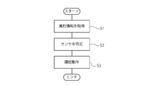
- FIG. 4 is a flow diagram showing a series of operations of the automatic door setting system;
- 3 is a block diagram of a control program for the automatic door setting system;
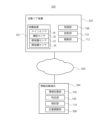
- FIG. 11 is a block diagram of an automatic door setting system according to a modification; 4 shows a screen for position adjustment.
- FIG. 1 is a perspective view of an automatic door system.
- the automatic door device 10 includes two sliding doors 12 as shown in FIG. Each sliding door 12 moves toward the opposite side in the width direction of the automatic door system 10 and opens, thereby allowing a pedestrian or an object to pass through the automatic door system 10 .
- fixing portions 14 are provided on both sides in the width direction of the sliding door 12 .
- the fixed part 14 is fixed to the frame on which the automatic door device 10 is installed.
- the sliding door 12 and the fixing part 14 face each other, and the space in front of the fixing part 14 constitutes an accommodation part for accommodating the sliding door 12 in the fully open state.
- a guard screen may be provided so as to face the fixed portion 14 .
- the automatic door device 10 is provided with a mesh 16 that accommodates the driving portion of the sliding door 12, which will be described later.
- the mesh 16 is arranged on the sliding door 12 and the fixed portion 14 so as to extend from one end of the fixed portion 14 to the other end of the fixed portion 14 in the width direction of the automatic door apparatus 10 .
- the automatic door device 10 includes a main sensor 18, an auxiliary sensor 20, and two open protection sensors 22L and 22R.
- the main sensor 18, the auxiliary sensor 20, and the open protection sensors 22L and 22R correspond to protection devices, each of which detects a person or an object within a predetermined area near the sliding door 12.
- Protective equipment for the automatic door system 10 refers to equipment in general that is provided to appropriately protect people or objects passing through the automatic door system 10 and/or people around the automatic door system 10, as described above. In addition to sensors, it also includes a camera for image analysis and physical switches such as an emergency stop button.
- the main sensor 18 has a predetermined detection area A ⁇ b>1 on the path of a person or object approaching the sliding door 12 .
- the main sensor 18 incorporates a plurality of optical sensors (not shown), and an area obtained by integrating the irradiation areas of the optical sensors becomes a detection area A1.
- the main sensor 18 detects this and outputs a detection signal.
- the detection signal from the main sensor 18 is also used to detect that there is no person or object within the detection area A1 when the sliding door 12 is closed. That is, the main sensor 18 also functions as a closed protection sensor.
- the auxiliary sensor 20 is a photoelectric sensor having a detection area A2 across the opening formed when the sliding door 12 is opened.
- the auxiliary sensor 20 is provided on a vertical frame facing the opening of the fixed portion 14 .
- the detection result of the auxiliary sensor 20 is used to detect that there is no person or object within the detection area A2 before or while the sliding door 12 is closed.
- the automatic door device 10 reversely drives the sliding door 12 toward the fully open state.
- the open protection sensors 22L, 22R have detection areas A3L, A3R in the vicinity of the housing portions of the sliding doors 12, respectively.
- the open protection sensors 22L and 22R are provided on the bottom surface of the blind 16 so that the accommodation portions are detection areas A3L and A3R.
- the detection results of the open protection sensors 22L, 22R are used to detect that there is no person or object within the detection areas A3L, A3R when the sliding door 12 is opened.
- the automatic door device 10 reversely drives the sliding door 12 and drives the sliding door 12 toward the fully closed state. let or stop.
- Fig. 2 is a block diagram of the automatic door setting system. In this embodiment, it is assumed that the automatic door setting system is built in the automatic door device. Therefore, the blocks of the automatic door setting system shown in FIG. 2 are implemented as hardware by an automatic door device.
- the automatic door setting system 100 includes a protection device 102, an information collection unit 104, an identification unit 106, a control unit 108, a diagnosis unit 110, a drive unit 112, and a notification unit 114. .
- the protection device 102 includes a main sensor 18, an auxiliary sensor 20, and two open protection sensors 22L, 22R.
- the protection device 102 detects a person or an object within the detection areas A1 to A3 near the front or back of the door, and outputs the detection result as a detection signal.
- Each sensor that constitutes the protection device 102 is connected to the same network, such as CAN. Being connected to the same network means that each component is connected to an open network or a closed network, and is connected so as to be able to communicate bidirectionally or unidirectionally.
- Attribute information indicating the type of sensor is assigned to each sensor that configures the protective device 102 . Attribute information is information composed of predetermined numbers or character strings, and is unique information assigned to each sensor.
- the information collection unit 104 is connected to the same network as the protection device 102, and collects attribute information of the protection device 102 via the network. Every time the information collecting unit 104 detects that it is ready to communicate with the protection device 102, that is, when the protection device 102 is newly connected to the network or when the protection device 102 is reconnected, the information collection unit 104 Collect attribute information of The information collecting unit 104 may collect attribute information of components other than the protective device 102 , such as the driving unit 112 .
- the identifying unit 106 identifies the attribute information of the sensors that constitute the protective device 102 from among the plurality of pieces of attribute information collected by the information collecting unit 104 .
- the identifying unit 106 stores attribute information of the main sensor 18, the auxiliary sensor 20, and the two open protection sensors 22L and 22R in advance.
- the identifying unit 106 collates a plurality of pieces of attribute information collected by the information collecting unit 104 with stored attribute information, and determines whether or not the attribute information is the attribute information of the protective device 102 . As a result of collation, when the collected attribute information matches the stored attribute information of the sensor, the identifying unit 106 identifies that the device having the collected attribute information is the sensor.
- the attribute information for example, information indicating a true/false value stored in a specific area of the storage unit of the sensor (so-called "flag information”) may be used.
- the true/false value indicates whether the sensor is the main sensor 18 or not.
- the information collecting unit 104 reads the information stored in the storage unit of the sensor, and the specifying unit 106 specifies that the sensor is the main sensor 18 by referring to the true/false value and the conditions of the true/false value. After each sensor is specified, the specifying unit 106 stores the attribute information of the specified sensor and outputs it to the control unit 108 .
- the control unit 108 causes the driving unit 112 to control opening and closing of the sliding door 12 (see FIG. 1).
- the control unit 108 detects a detection signal from the protective device 102 and outputs an open drive signal or a close drive signal for the sliding door 12 to the drive unit 112 based on the detection signal.
- control unit 108 causes the drive unit 112 to perform an operation to confirm the opening/closing of the sliding door 12 when the sensor is specified by the specifying unit 106 .
- the confirmation work is performed, for example, after the installation work of the automatic door apparatus 10 is performed, each component is installed at a predetermined position, and the sensor is specified by the specifying unit 106 .
- the control unit 108 sequentially outputs the open drive signal and the close drive signal to the drive unit 112 .
- the order of outputting the signals may be reversed. Therefore, the open drive signal may be output after the close drive signal is output.
- the diagnosis unit 110 diagnoses the state of the sensor.
- the diagnosis unit 110 diagnoses the state of the sensor by checking whether the sensor is activated, whether the sensor is communicably connected to a control system including the control unit 108, and whether the sensor can perform accurate arithmetic processing. It refers to diagnosing at least one of whether or not there is.
- the diagnosis unit 110 requests the sensor to perform predetermined information processing, and diagnoses whether the sensor is normal based on the processing result on the sensor side. Specifically, the diagnosis unit 110 sends predetermined problem information and a request for an answer to the problem to the sensor, and diagnoses the state of the sensor based on the information returned from the sensor. Problem information means information from which an answer can be derived according to rules such as computation.
- Any computation may be used as long as the sensor does not have the correct answer (that is, it is unknown to the sensor) and only the diagnosis unit 110 has the correct answer.
- a four arithmetic operation consisting of two terms can be used as the arithmetic operation.
- the information regarding the calculation may be the mathematical expression itself.
- a database in which a plurality of types of formulas and formula numbers are associated in advance is prepared, the database is stored in the sensor and the diagnostic unit 110, and the formula number is transmitted from the diagnostic unit 110 to the sensor as information related to calculation. good.
- different formulas may be transmitted for each sensor.
- the formula that the diagnostic unit 110 transmits to the sensor may include variables.
- the sensor substitutes a numerical value unique to the sensor, such as the identification number of the sensor or the device number, into a variable, and returns the calculation result to the diagnosis unit 110 . If the calculation result from the sensor is erroneous, it can be understood that at least some kind of abnormality has occurred in the calculation processing section of the sensor. In such a case, it can be inferred that some kind of abnormality has occurred in the detection section of the sensor. Diagnose.
- the diagnostic unit 110 may self-diagnose the state of the sensor.
- Self-diagnosis refers to diagnosing whether or not a sensor has an abnormality in its own function.
- Diagnosis unit 110 causes the sensor to perform self-diagnosis and receives the result.
- the sensor checks whether the sensor detection function is normal, whether the sensor performance is degraded, and whether there is environmental noise in the detection area (foreign matter in the detection area, dirt on the lens, etc.). Diagnose.
- the diagnosis unit 110 simultaneously transmits a self-diagnosis instruction and a reply request to the sensor.
- the sensor concurrently performs self-diagnosis and computation in response to the reply request, and simultaneously transmits the self-diagnosis result and the computation result to the diagnostic unit 110 .
- the diagnosis unit 110 may transmit a self-diagnosis instruction to the sensor after receiving the calculation result in response to the reply request from the sensor.
- the diagnosis unit 110 diagnoses whether or not an abnormality has occurred in the sensor, taking into account the result of the self-diagnosis by the sensor and the calculation result for the response request.
- the reliability of the diagnosis result can be improved by performing the diagnosis in consideration of the self-diagnosis result of the sensor.
- the diagnosis unit 110 either holds in advance the answers to the calculations sent to the sensors, or performs calculations by itself each time it sends calculations to the sensors. Therefore, the diagnosis unit 110 holds the correct answer of the calculation sent to the sensor. Diagnosis unit 110 compares the response from the sensor with the correct answer held by itself. If the answer and the correct answer are the same, the diagnosis unit 110 diagnoses that the sensor is normal. On the other hand, if the answer and the correct answer are different, the diagnosis unit 110 diagnoses that the sensor is not normal. Diagnosis section 110 transmits the diagnosis result to control section 108 . Further, the diagnosis result of the diagnosis unit 110 may be output via an output means such as a display unit to inform the administrator of the diagnosis result.
- the drive unit 112 has drive mechanisms such as a door engine and pulleys, and operates the drive mechanisms based on the open drive signal or the close drive signal received from the control unit 108 . Thereby, the sliding door 12 is driven according to the detection signal of the protective device 102 .
- the notification unit 114 notifies the installer of various types of information.
- the information notified by the notification unit 114 includes information indicating that attribute information not held by the identification unit 106 has been collected by the information collection unit 104 and a diagnosis result by the diagnosis unit 110 .
- the notification unit 114 may be an LED or the like that blinks when attribute information not held by the identification unit 106 is collected, for example, and the diagnosis result by the diagnosis unit 110 is abnormal. A monitor or the like for displaying to the installer may be used. Further, when the diagnosis result by the diagnosis unit 110 is normal, the notification unit 114 may notify the installer to that effect.
- FIG. 3 is a flow diagram showing a series of operations of the automatic door setting system.
- the automatic door setting system 100 is activated and starts a series of processes after the components of the automatic door device 10 are installed at predetermined positions.
- the information collecting unit 104 acquires the attribute information of the devices connected to the network via the network (step S1).
- the specifying unit 106 refers to the attribute information acquired by the information collecting unit 104 to specify the main sensor 18, the auxiliary sensor 20, and the two open protection sensors 22L and 22R (step S2).
- the control unit 108 causes the driving unit 112 to perform an opening/closing confirmation operation.
- the diagnostic unit 110 diagnoses whether the protective device 102 is functioning normally (step S3). After completing the diagnosis, the automatic door setting system 100 ends a series of processes.
- FIG. 4 is a block diagram of a control program for the automatic door setting system.
- control program 200 instructs a protection instruction unit 202 that outputs an instruction to the protection device 102, a collection instruction unit 204 that outputs an instruction to the information collection unit 104, and an identification unit 106. and a diagnosis instruction unit 208 that outputs an instruction to the diagnosis unit 110 .
- the protection instruction unit 202 causes the protection device 102 to detect a person or object within the detection areas A1 to A3 (see FIG. 1) and output the detection result as a detection signal.
- the collection instruction unit 204 causes the information collection unit 104 to collect attribute information.
- the specifying unit 206 causes the specifying unit 106 to specify sensor attribute information.
- the diagnosis instruction unit 208 causes the diagnosis unit 110 to diagnose the state of the sensor during the confirmation operation.
- the automatic door setting system 100 it is possible to automatically identify the constituent devices simply by installing the constituent devices at predetermined positions and connecting the constituent devices to each other via a network.
- the installation work process of the automatic door device 10 can be reduced.
- FIG. 5 is a block diagram of an automatic door setting system according to a modification.
- the automatic door setting system 300 according to the modified example includes an automatic door device 302 and an information collection terminal 304 .
- the automatic door device 302 and the information collection terminal 304 are connected via a network 306 .
- the automatic door device 302 includes a protection device 102 , a control section 108 , a diagnosis section 110 and a drive section 112 .
- the information collection terminal 304 also includes an information collection unit 104 , a specification unit 106 and a notification unit 114 .
- the information collection terminal 304 is a terminal that can be operated by the installer, and is configured so that the installer can input predetermined information or output predetermined information to the installer via the notification unit 114 .
- a part of the configuration of the automatic door setting system 300 may be incorporated in the information collection terminal 304 in this way.
- the information collection terminal 304 may also include a position adjustment unit 308 for adjusting the size and position of the detection area.
- the position adjustment unit 308 displays a position adjustment screen to the installer via the notification unit 114, and outputs to each sensor an instruction to adjust the size and position of the detection area according to the input from the installer.
- Fig. 6 shows the position adjustment screen.
- the screen shows the sliding door 12 and the detection area A1.
- a detection area A1 is composed of a plurality of detection spots 310 .
- the sensor corresponding to the detection spot 310 indicated by the solid line is turned on, and the detection spot 310 is in a detectable state.
- the sensor corresponding to the detection spot 310 indicated by the dashed line is turned off, and the detection spot 310 is in a non-detectable state.
- the installer selects the detection spot 310 to be turned ON and the detection spot 310 to be turned OFF while referring to the screen, and inputs an instruction to the information collection terminal 304 to adjust the size and position of the detection area.
- the detection areas A2 and A3 may be made adjustable.
- the present invention relates to an automatic door setting system, an automatic door setting method, and an automatic door setting program.
Landscapes
- Power-Operated Mechanisms For Wings (AREA)
Priority Applications (1)
| Application Number | Priority Date | Filing Date | Title |
|---|---|---|---|
| JP2023545535A JP7733120B2 (ja) | 2021-09-03 | 2022-08-26 | 自動ドア設定システム、自動ドア設定方法、及び自動ドア設定プログラム |
Applications Claiming Priority (2)
| Application Number | Priority Date | Filing Date | Title |
|---|---|---|---|
| JP2021143904 | 2021-09-03 | ||
| JP2021-143904 | 2021-09-03 |
Publications (1)
| Publication Number | Publication Date |
|---|---|
| WO2023032864A1 true WO2023032864A1 (ja) | 2023-03-09 |
Family
ID=85412731
Family Applications (1)
| Application Number | Title | Priority Date | Filing Date |
|---|---|---|---|
| PCT/JP2022/032281 Ceased WO2023032864A1 (ja) | 2021-09-03 | 2022-08-26 | 自動ドア設定システム、自動ドア設定方法、及び自動ドア設定プログラム |
Country Status (2)
| Country | Link |
|---|---|
| JP (1) | JP7733120B2 (https=) |
| WO (1) | WO2023032864A1 (https=) |
Citations (4)
| Publication number | Priority date | Publication date | Assignee | Title |
|---|---|---|---|---|
| JP2013023812A (ja) * | 2011-07-14 | 2013-02-04 | Nabtesco Corp | 自動ドアの制御モード切替装置およびそれを用いた自動ドア |
| JP2014528221A (ja) * | 2011-10-06 | 2014-10-23 | ナブテスコ株式会社 | 自動ドアの遠隔管理システム |
| JP2016204927A (ja) * | 2015-04-20 | 2016-12-08 | 株式会社ミズタ | 低温状態で物品を保管する倉庫の管理システム、及び、管理方法 |
| JP2021102898A (ja) * | 2019-12-25 | 2021-07-15 | オプテックス株式会社 | ドア開閉制御システム |
-
2022
- 2022-08-26 WO PCT/JP2022/032281 patent/WO2023032864A1/ja not_active Ceased
- 2022-08-26 JP JP2023545535A patent/JP7733120B2/ja active Active
Patent Citations (4)
| Publication number | Priority date | Publication date | Assignee | Title |
|---|---|---|---|---|
| JP2013023812A (ja) * | 2011-07-14 | 2013-02-04 | Nabtesco Corp | 自動ドアの制御モード切替装置およびそれを用いた自動ドア |
| JP2014528221A (ja) * | 2011-10-06 | 2014-10-23 | ナブテスコ株式会社 | 自動ドアの遠隔管理システム |
| JP2016204927A (ja) * | 2015-04-20 | 2016-12-08 | 株式会社ミズタ | 低温状態で物品を保管する倉庫の管理システム、及び、管理方法 |
| JP2021102898A (ja) * | 2019-12-25 | 2021-07-15 | オプテックス株式会社 | ドア開閉制御システム |
Also Published As
| Publication number | Publication date |
|---|---|
| JP7733120B2 (ja) | 2025-09-02 |
| JPWO2023032864A1 (https=) | 2023-03-09 |
Similar Documents
| Publication | Publication Date | Title |
|---|---|---|
| JP3202396B2 (ja) | エレベータの異常解析データ収集装置 | |
| JP3872252B2 (ja) | エレベータの異常音検出装置及び方法 | |
| KR102327807B1 (ko) | 인공지능 기반 승강기 위험상황 자동 예측판단시스템 | |
| CN110861988A (zh) | 一种电梯异常的声纹识别及故障诊断监控报警系统 | |
| JPH092752A (ja) | エレベータの診断装置 | |
| JP2019104612A (ja) | エレベータドアの異常診断システム及び異常診断方法 | |
| US6439350B1 (en) | Differentiating elevator car door and landing door operating problems | |
| CN113916277A (zh) | 用于探测技术系统中异常的方法及设备 | |
| JP6480046B1 (ja) | エレベータドアに設置された光軸センサの故障診断システムおよび故障診断方法 | |
| US20220026313A1 (en) | Method and device for detecting anomalies in sensor recordings of a technical system | |
| WO2023032864A1 (ja) | 自動ドア設定システム、自動ドア設定方法、及び自動ドア設定プログラム | |
| KR101917808B1 (ko) | 승강기 영상 감시 시스템 및 승강기 영상 감시 방법 | |
| JP6673737B2 (ja) | システム機器の異常診断装置、エレベーターの異常診断装置及びエレベーターの異常診断方法 | |
| JP7747447B2 (ja) | 自動ドア装置及び自動ドア診断システム | |
| WO2007134102A2 (en) | System and method of agent self-repair within an intelligent agent system | |
| CN112119027B (zh) | 用于检测电梯中的故障的方法和电梯控制器 | |
| KR101874985B1 (ko) | 실시간 엔코더 변위 감시를 이용한 자동심사대 장애 예측관리 시스템 | |
| JP2002332772A (ja) | 自動ドアの異常診断装置 | |
| KR102867874B1 (ko) | 화면 출력 기반 이상 상태 감지 방법 및 장치 | |
| JP3223347B2 (ja) | 検知センサの動作診断装置 | |
| KR20200092833A (ko) | 전투 체계의 장비 모니터링 장치 | |
| JPH09136775A (ja) | エレベーターの動作状態表示装置 | |
| JP4565993B2 (ja) | 警備装置、警備方法、監視システム | |
| KR0179886B1 (ko) | 승강기 고장 검출장치 | |
| JP7256091B2 (ja) | 自動ドア装置の検査システム、自動ドア装置の検査装置、自動ドア装置の検査方法 |
Legal Events
| Date | Code | Title | Description |
|---|---|---|---|
| 121 | Ep: the epo has been informed by wipo that ep was designated in this application |
Ref document number: 22864448 Country of ref document: EP Kind code of ref document: A1 |
|
| WWE | Wipo information: entry into national phase |
Ref document number: 2023545535 Country of ref document: JP |
|
| NENP | Non-entry into the national phase |
Ref country code: DE |
|
| 122 | Ep: pct application non-entry in european phase |
Ref document number: 22864448 Country of ref document: EP Kind code of ref document: A1 |