WO2023032539A1 - 回転装置、モータ、及びポンプ - Google Patents
回転装置、モータ、及びポンプ Download PDFInfo
- Publication number
- WO2023032539A1 WO2023032539A1 PCT/JP2022/029181 JP2022029181W WO2023032539A1 WO 2023032539 A1 WO2023032539 A1 WO 2023032539A1 JP 2022029181 W JP2022029181 W JP 2022029181W WO 2023032539 A1 WO2023032539 A1 WO 2023032539A1
- Authority
- WO
- WIPO (PCT)
- Prior art keywords
- opposing
- vibration
- rotating device
- facing
- vibrating
- Prior art date
- Legal status (The legal status is an assumption and is not a legal conclusion. Google has not performed a legal analysis and makes no representation as to the accuracy of the status listed.)
- Ceased
Links
Images




















Classifications
-
- F—MECHANICAL ENGINEERING; LIGHTING; HEATING; WEAPONS; BLASTING
- F04—POSITIVE - DISPLACEMENT MACHINES FOR LIQUIDS; PUMPS FOR LIQUIDS OR ELASTIC FLUIDS
- F04D—NON-POSITIVE-DISPLACEMENT PUMPS
- F04D29/00—Details, component parts, or accessories
- F04D29/66—Combating cavitation, whirls, noise, vibration or the like; Balancing
- F04D29/661—Combating cavitation, whirls, noise, vibration or the like; Balancing especially adapted for elastic fluid pumps
-
- B—PERFORMING OPERATIONS; TRANSPORTING
- B06—GENERATING OR TRANSMITTING MECHANICAL VIBRATIONS IN GENERAL
- B06B—METHODS OR APPARATUS FOR GENERATING OR TRANSMITTING MECHANICAL VIBRATIONS OF INFRASONIC, SONIC, OR ULTRASONIC FREQUENCY, e.g. FOR PERFORMING MECHANICAL WORK IN GENERAL
- B06B1/00—Methods or apparatus for generating mechanical vibrations of infrasonic, sonic, or ultrasonic frequency
- B06B1/02—Methods or apparatus for generating mechanical vibrations of infrasonic, sonic, or ultrasonic frequency making use of electrical energy
- B06B1/06—Methods or apparatus for generating mechanical vibrations of infrasonic, sonic, or ultrasonic frequency making use of electrical energy operating with piezoelectric effect or with electrostriction
-
- F—MECHANICAL ENGINEERING; LIGHTING; HEATING; WEAPONS; BLASTING
- F04—POSITIVE - DISPLACEMENT MACHINES FOR LIQUIDS; PUMPS FOR LIQUIDS OR ELASTIC FLUIDS
- F04B—POSITIVE-DISPLACEMENT MACHINES FOR LIQUIDS; PUMPS
- F04B43/00—Machines, pumps, or pumping installations having flexible working members
- F04B43/02—Machines, pumps, or pumping installations having flexible working members having plate-like flexible members, e.g. diaphragms
- F04B43/04—Pumps having electric drive
-
- F—MECHANICAL ENGINEERING; LIGHTING; HEATING; WEAPONS; BLASTING
- F04—POSITIVE - DISPLACEMENT MACHINES FOR LIQUIDS; PUMPS FOR LIQUIDS OR ELASTIC FLUIDS
- F04D—NON-POSITIVE-DISPLACEMENT PUMPS
- F04D11/00—Other rotary non-positive-displacement pumps
-
- F—MECHANICAL ENGINEERING; LIGHTING; HEATING; WEAPONS; BLASTING
- F04—POSITIVE - DISPLACEMENT MACHINES FOR LIQUIDS; PUMPS FOR LIQUIDS OR ELASTIC FLUIDS
- F04D—NON-POSITIVE-DISPLACEMENT PUMPS
- F04D29/00—Details, component parts, or accessories
- F04D29/26—Rotors specially for elastic fluids
- F04D29/32—Rotors specially for elastic fluids for axial flow pumps
- F04D29/38—Blades
- F04D29/384—Blades characterised by form
-
- F—MECHANICAL ENGINEERING; LIGHTING; HEATING; WEAPONS; BLASTING
- F04—POSITIVE - DISPLACEMENT MACHINES FOR LIQUIDS; PUMPS FOR LIQUIDS OR ELASTIC FLUIDS
- F04D—NON-POSITIVE-DISPLACEMENT PUMPS
- F04D29/00—Details, component parts, or accessories
- F04D29/66—Combating cavitation, whirls, noise, vibration or the like; Balancing
-
- F—MECHANICAL ENGINEERING; LIGHTING; HEATING; WEAPONS; BLASTING
- F04—POSITIVE - DISPLACEMENT MACHINES FOR LIQUIDS; PUMPS FOR LIQUIDS OR ELASTIC FLUIDS
- F04D—NON-POSITIVE-DISPLACEMENT PUMPS
- F04D29/00—Details, component parts, or accessories
- F04D29/66—Combating cavitation, whirls, noise, vibration or the like; Balancing
- F04D29/669—Combating cavitation, whirls, noise, vibration or the like; Balancing especially adapted for liquid pumps
-
- H—ELECTRICITY
- H02—GENERATION; CONVERSION OR DISTRIBUTION OF ELECTRIC POWER
- H02N—ELECTRIC MACHINES NOT OTHERWISE PROVIDED FOR
- H02N2/00—Electric machines in general using piezoelectric effect, electrostriction or magnetostriction
- H02N2/10—Electric machines in general using piezoelectric effect, electrostriction or magnetostriction producing rotary motion, e.g. rotary motors
- H02N2/103—Electric machines in general using piezoelectric effect, electrostriction or magnetostriction producing rotary motion, e.g. rotary motors by pressing one or more vibrators against the rotor
-
- H—ELECTRICITY
- H02—GENERATION; CONVERSION OR DISTRIBUTION OF ELECTRIC POWER
- H02N—ELECTRIC MACHINES NOT OTHERWISE PROVIDED FOR
- H02N2/00—Electric machines in general using piezoelectric effect, electrostriction or magnetostriction
- H02N2/10—Electric machines in general using piezoelectric effect, electrostriction or magnetostriction producing rotary motion, e.g. rotary motors
- H02N2/12—Constructional details
Definitions
- the present invention relates to rotating devices, motors, and pumps.
- Patent Literature 1 discloses a technique of obtaining a pump effect using ultrasonic waves with a simple structure.
- Non-Patent Document 1 discloses a phenomenon in which when an object is brought close to a vibrator, the object is attracted to the vibrator.
- the purpose of the present invention is to provide a novel technology that can be applied to various uses using a vibrator.
- a rotating device includes a vibrator having a vibrating surface perpendicular to a vibrating direction, and a facing surface facing the vibrating surface, and rotating about the vibrating direction of the vibrator.
- Each of the vibrating surface and the opposing surface has a parallel region facing each other in parallel and an impeller region three-dimensionally formed on at least one of them.
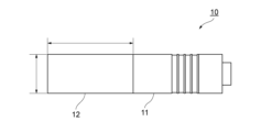
- FIG. 1 is a conceptual diagram showing an example of a configuration of a rotating device according to one embodiment
- FIG. 1 is a conceptual diagram showing an example of a configuration of a vibrator according to an embodiment
- FIG. 1 is a conceptual diagram showing an example of a configuration of a vibrator according to an embodiment
- FIG. 4 is a diagram for explaining an example of vibration characteristics of a vibrator according to one embodiment
- FIG. 4 is a diagram schematically showing an example of the shape of a vibrator according to one embodiment
- FIG. 4 is a diagram schematically showing an example of the shape of a vibrator according to one embodiment
- FIG. 4 is a diagram schematically showing an example of the shape of a vibrator according to one embodiment
- FIG. 4 is a diagram schematically showing an example of the shape of a vibrator according to one embodiment
- FIG. 4 is a diagram schematically showing an example of the shape of a vibrator according to one embodiment
- FIG. 4 is a diagram schematically showing an example of the shape of a vibrator according
- FIG. 4 is a diagram schematically showing an example of the shape of a vibrator according to one embodiment
- FIG. 4 is a diagram schematically showing an example of the shape of a vibrator according to one embodiment
- FIG. 5 is a diagram showing the relationship between the vibration amplitude of the vibrating device and the measurement result of the rotation speed for the counterpart according to one embodiment.
- FIG. 5 is a diagram showing the relationship between the vibration amplitude of the vibrating device and the measurement result of the rotation speed for the counterpart according to one embodiment.
- FIG. 5 is a diagram showing the relationship between the vibration amplitude of the vibrating device and the measurement result of the rotation speed for the counterpart according to one embodiment.
- FIG. 5 is a diagram showing the relationship between the vibration amplitude of the vibrating device and the measurement result of the rotation speed for the counterpart according to one embodiment.
- FIG. 5 is a diagram showing the relationship between the vibration amplitude of the vibrating device and the measurement result of the rotation speed for the counterpart according to one embodiment.
- FIG. 5 is a diagram showing the relationship between the vibration amplitude of the vibrating device and the measurement result of the rotation speed for the counterpart according to one embodiment.
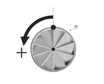
- It is a conceptual diagram for demonstrating the rotation direction of the opposing child which concerns on one Embodiment.
- It is a conceptual diagram for demonstrating the modification of the rotation apparatus which concerns on one Embodiment.
- the rotating device 1 includes a vibrating device 10 and an opposing piece 20 .
- a vibrating device 10 includes a vibrator 11 and a horn 12 .
- the vibrating device 10 may be called a vibrator.
- the vibration device 10 is fixed by a fixture 30 so that the longitudinal direction of the vibration device 10, which is the vibration direction of the vibration device 10, is in the direction of gravity.
- the vibrating device 10 has a planar and circular vibrating surface perpendicular to the vibrating direction at one longitudinal end (lower end in the example of FIG. 1) of the vibrating device 10 .
- the vibrating device 10 is connected to a power source (not shown) to obtain drive power.
- the vibrating device 10 has a circuit (not shown) for generating and controlling vibration as a control section.
- the lower end of the vibrating device 10 and the counterpart 20 are submerged in the water filled in the water tank 50 .
- a Z-axis stage 40 adjusts the position of the water tank 50 in the Z-axis direction.
- the temperature probe 60 is fixed by the fixture 30 so as to be able to measure the water temperature inside the water tank 50 .
- the opposing member 20 has a plate shape such as a disc shape, for example.
- the opposing member 20 has two circular surfaces. At least one of the two circular surface portions of the opposing member 20 has a flat area and an impeller area.
- the planar region of the surface portion (opposing surface) of the opposing member 20 is parallel to the vibrating surface of the vibrating device 10. Also referred to as parallel regions in the description of .
- the impeller area is an area in which a three-dimensional impeller shape is formed. A point-symmetric three-dimensional pattern that is not impeller-shaped may be formed in the impeller region.
- the diameter of the surface portion of the opposing member 20 and the diameter of the vibration surface of the vibration device 10 are the same.
- the same diameter does not necessarily mean completely the same diameter.
- the vibrating device 10 When the vibrating device 10 is vibrated with the lower end of the vibrating device 10 submerged in the water of the water tank 50, and the surface portion (opposing surface) having the parallel region and the impeller region of the opposing member 20 approaches the vibrating surface of the vibrating device 10, , the opposing surface of the opposing member 20 is kept in a state of being attracted to the vibration surface of the vibrating device 10 .
- the rotating device 1 does not have a member that supports the opposing piece 20 .
- Vibration by the vibrating device 10 is, but not limited to, for example, ultrasonic vibration with a frequency of 20 kHz or higher. Vibration by the vibrating device 10 is, for example, but not limited to, a simple harmonic motion.
- the vibrating device 10 vibrates and the opposing member 20 is attracted, a self-centering effect is generated between the vibrating surface of the vibrating device 10 and the surface of the opposing member 20, so that the vibrating surface of the vibrating device 10
- the position of the central portion and the position of the central portion of the face portion of the opposing piece 20 are adjacent positions.
- the diameter of the surface portion of the opposing member 20 and the diameter of the vibration surface of the vibration device 10 are the same.
- the vibrating device 10 vibrates, and when the vibrating surface of the vibrating device 10 and the surface portion of the opposing member 20 face each other, the ends of the vibrating surface of the vibrating device 10 on the vibrating surface face each other. It faces the edge on the surface of the surface of the child 20 .
- the counterpiece 20 rotates around the vibration direction of the vibrating device 10 .
- the principle of the rotation is not clear, it is caused by the pressure generated by the vibration of the vibrating surface of the vibrating device 10, and by the water flow flowing through the gap between the vibrating device 10 and the opposing member 20 and the vibration of the vibrating surface.
- the opposing member 20 rotates due to the generated acoustic stream or the like hitting the surface of the opposing member 20 .
- the details of the rotation of the counterpart 20 will be described later.
- the surface portion of the opposing member 20 has the parallel area and the impeller area, but the present invention is not limited to this.
- the vibration surface of the vibration device 10 may have the parallel area and the impeller area instead of the surface portion of the counterpiece 20 . The same applies to embodiments described later.
- the rotating device 1 includes the vibrating device 10 (oscillator) and the counterpart 20 .
- the vibration device 10 has a vibration plane perpendicular to the vibration direction.
- the opposing member 20 has a surface facing the vibration surface of the vibration device 10 and rotates about the vibration direction of the vibration device 10 as an axis.
- the vibrating surface of the vibrating device 10 and the opposing surface of the opposing member 20 each have a parallel region facing each other in parallel and an impeller region formed three-dimensionally on at least one of them.
- the rotating device 1 can realize a novel rotating device using the vibrating device 10 .
- the counterpart 20 rotates without contacting the vibrating device 10 , wear and damage due to contact with the vibrating device 10 are less likely to occur. As a result, it is possible to realize the rotating device 1 with high durability.
- the vibrating device 10 only needs to be configured to generate vibration, and its specific configuration is not limited to the configuration described below.
- the vibrator 11 of the vibrating device 10 is constructed by alternately sandwiching donut-shaped piezoelectric ceramics and electrode plates, further sandwiching the two ends between metal blocks, and tightening them with through bolts. A voltage is applied to the electrode plates so that the vibrator 11 is polarized in its axial direction. By applying an AC voltage from the circuit to the electrode plates, expansion and contraction are caused by the inverse piezoelectric effect, and the vibrator 11 vibrates in a unidirectional vibration mode. Since the vibrator 11 is constructed by tightening it with a through bolt, even a piezoelectric ceramic that is weak against tensile force can withstand vibration amplitude and operate as a high-output vibrator.
- a horn 12 is connected to one end of the vibrator 11 in the axial direction.
- the horn 12 is a member connected to the vibrator 11 so that the vibrating surface of the vibrating device 10 satisfies desired conditions such as shape, pattern, presence or absence of holes, and material.
- horn 12 is configured in a cylindrical shape.
- the bottom surface of the horn 12, which serves as the vibration surface of the vibrating device 10, is circular.
- Horn 12 is connected to vibrator 11 so that its axis is coaxial with the axis of vibrator 11 .
- the horn 12 is made of any member, but is made of a metal member such as stainless steel, for example.
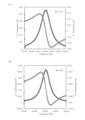
- FIG. 3 shows the results of measurement of the vibration characteristics of the vibration device 10 fixed by the fixture 30 using an impedance analyzer.
- FIG. 3 shows the relationship between the frequency of the alternating voltage in the circuit of the vibration device 10 and the conductance (real part G) and susceptance (imaginary part B) of the admittance.
- FIG. 3(1) shows the result of measuring the vibration characteristics of the vibration device 10 in the air.
- FIG. 3(2) shows the result of measuring the vibration characteristics of the vibration device 10 in water.
- the frequency at which the real part G takes a maximum value (unit [S]) is the resonance frequency of the vibration device 10 . According to FIG.
- the vibration device 10 resonates at a frequency of 26.5-26.6 kHz in air and water. It is possible to track the resonance frequency of the vibrating device 10 using the phase measurement of the admittance. According to FIG. 3, the maximum value of the real part G in water is approximately half the maximum value of the real part G in air. Therefore, FIG. 3 shows that in order to obtain the same vibration amplitude in water and in air, it is necessary to apply about twice as much voltage in water as in air.
- the counterpart 20a is disc-shaped.
- At least one of the two opposing circular surface portions of the counterpiece 20a has an impeller area and a plane area 203 surrounding the impeller area.
- the impeller region has a plurality of slanted surfaces 201 and a plurality of vertical surfaces 202 .
- the inclined surface 201 is a fan-shaped surface that is inclined with respect to the flat area 203 .
- the inclined plane 201 has a vertex at the point of contact between the planar region 203 and the radiation, and is inclined toward the other radiation of the inclined plane 201 .
- the angle of inclination is, for example, but not limited to, 10° with respect to the planar region 203 .
- the vertical plane 202 is a plane perpendicular to the planar region 203 and extending between the ends of the two inclined planes 201 .
- a plurality of tangent lines (hereinafter also referred to as “radiation lines”) where the inclined surface 201 and the vertical surface 202 meet radially extend from the center of the impeller region to the plane region 203 .
- the opposing member 20a has a convex portion formed on the surface portion along the edge of the surface portion and having the planar region 203 as the upper surface. Since the convex portion has a higher region than the impeller region, in the present embodiment, the convex portion of the opposing member 20a is also referred to as a rim, and the impeller region is recessed more than the plane region 203. A site is also referred to as a recess.
- the vibration surface of the vibrating device 10 and the surface portion (opposing surface) having the projections and recesses of the opposing member 20a face each other, the vibration surface of the vibrating device 10 and the opposing surface of the opposing member 20a form a space. is formed. In this case, the vibrating surface of the vibrating device 10 is not in contact with the protruding portion of the opposing member 20a, and there is a predetermined gap between the vibrating surface of the vibrating device 10 and the protruding portion of the opposing member 20a.
- the diameter of the circular surface portion of the counter piece 20a is 40 mm, and the width of the upper surface of the flat area 203 in the transverse direction is 1.5 mm.
- the thickness of the opposing member 20a is 2.5 mm.
- the surface portion of the opposing member 20a and the vibration surface of the vibrating device 10 are circular, and the diameter of the surface portion of the opposing member 20a and the diameter of the vibrating surface of the vibrating device 10 are the same.
- the vibrating device 10 vibrates, and when the vibrating surface of the vibrating device 10 faces the surface of the opposing member 20a, the end of the vibrating surface of the vibrating device 10 is aligned with the end of the surface of the opposing member 20a. Oppose.
- FIGS. 4B to 4E The examples of the counterparts 20 shown in FIGS. 4B to 4E will be described with a focus on differences from the counterparts 20a shown in FIG. 4A or other examples of the counterparts 20.
- FIG. 4A The examples of the counterparts 20 shown in FIGS. 4B to 4E will be described with a focus on differences from the counterparts 20a shown in FIG. 4A or other examples of the counterparts 20.
- FIG. 4E The examples of the counterparts 20 shown in FIGS. 4B to 4E will be described with a focus on differences from the counterparts 20a shown in FIG. 4A or other examples of the counterparts 20.
- the inclined surface 201 of the opposing member 20b shown in FIG. 4B differs from the opposing member 20a in the method of inclination.
- the slanted surface 201 of the counter 20b is slanted toward the point of contact between the other ray and the planar region 203, with the position of one ray on the slanted surface 201 being the highest.
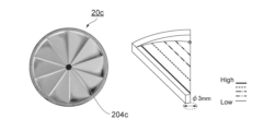
- the opposing member 20c shown in FIG. 4C differs from the opposing member 20b in that it has a through-hole 204c in the central portion of the surface portion.
- the opposing member 20c has a through hole 204c formed from the center portion of one of the two surface portions facing in parallel to the opposing member 20c toward the other surface portion (back surface of the opposing member 20c).
- the diameter of the through-hole 204c is, but not limited to, 3 mm.
- the presence of the through hole 204c in the central portion of the impeller region stabilizes the rotation of the opposing piece 20c.
- the opposing member 20d shown in FIG. 4D is different from the opposing member 20c in that it has a through hole 204c at the contact point between the radiation and the planar region 203, not at the central portion of the surface portion.
- the vertical surface 202e of the opposing member 20e shown in FIG. 4E is curved unlike the vertical surface 202 of the opposing member 20a which is flat. In the example shown in FIG. 4E, vertical surface 202e is curved to form a depression in top view. Further, the opposing member 20e differs from the opposing member 20a in that it has a through hole 204e in the central portion of the face portion.
- an AC voltage was generated by a function generator, amplified by a high-speed amplifier, and applied to the vibrator 11 of the vibration device 10 to excite the vibrator 11.
- the frequency of the applied AC voltage is 26.5 kHz, which is the resonance frequency of the vibrator 11 .
- the temperature of the water in the water tank 50 in which the lower end of the vibrating device 10 and the counterpiece 20 were immersed was kept within the range of 20°C to 30°C.
- the rotational speed of the opposing member 20 was measured with the naked eye using a stopwatch during low-speed rotation, and was measured from a moving image captured on video during high-speed rotation.
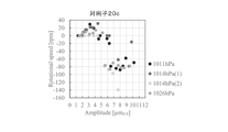
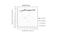
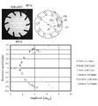
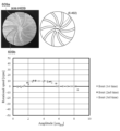
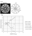
- FIGS. 5A to 5E show the measurement results of the rotation speed (Rotational speed) of the opposing members with respect to the vibration amplitude (Amplitude) of the vibrating device 10 for each of the opposing members 20a to 20e. The measurement results are shown for each atmospheric pressure condition.
- counterclockwise rotation in the top view of the impeller region of the opposing member 20 is defined as positive rotation of the opposing member 20, and the rotation speed is indicated by a positive value in FIGS. 5A to 5E.
- the clockwise rotation is the negative direction rotation of the counterpiece 20, and the rotation speed is indicated by a negative value in FIGS. 5A to 5E.
- FIGS. 5A to 5E different rotation characteristics are exhibited depending on the shape of the opposing piece 20.
- the opponents 20b, 20c, and 20e tend to increase in rotational speed as the vibration amplitude of the vibration device 10 increases.
- the counterpieces 20c and 20e having a through hole in the central portion of the surface portion (impeller region) have less variation in measurement results than the other counterpieces 20.
- FIG. Therefore, it can be understood that the rotation of the counterpart 20c is more stabilized by having the through hole in the central portion of the face portion.
- the rotating device 1 has one vibrating device, but in Modification 1, the rotating device 1 has two vibrating devices.
- the rotating device 1 includes a vibrating device 101 , a vibrating device 102 , and a counterpart 211 .
- the vibrating device 101 and the vibrating device 102 are configured similarly to the vibrating device 10 .
- the vibration device 101 has a first vibration plane perpendicular to the vibration direction.
- the vibration device 102 has a second vibration plane perpendicular to the vibration direction.
- the vibration device 101 and the vibration device 102 are installed such that the first vibration surface and the second vibration surface are opposed to each other.
- a counterpart 211 is placed between the first vibration surface and the second vibration surface.
- the opposing member 211 has a plate shape such as a disc shape, for example.
- Opponent 211 has two circular surface portions.
- the first vibrating surface, the second vibrating surface, and the opposing member 211 are submerged in the water filled in the water tank 501 .
- the first surface portion 211a and the second surface portion 211b of the opposing member 211 each have the same planar area and impeller area as in the above embodiment.
- the first surface portion 211a is the surface facing the first vibration surface
- the second surface portion 211b is the surface opposite the second vibration surface. becomes.
- the diameter of the first surface portion 211a and the second surface portion 211b is the same as the diameter of the first vibration surface and the second vibration surface.
- the impeller region may be formed on the first vibration surface and the second vibration surface instead of the first surface portion 211a and the second surface portion 211b.
- the first surface portion 211a has a shape that does not repel the rotational force generated by the water flow, the acoustic flow, etc. hitting the first surface portion 211a and the rotational force generated by the water flow, the acoustic flow, etc. Impeller regions of 211a and second surface portion 211b are formed.
- the vibration device 101 has the first vibration plane perpendicular to the vibration direction.
- the vibration device 102 has a second vibration plane perpendicular to the vibration direction.
- the opposing member 211 has a first surface portion 211a facing the first vibration surface and a second surface portion 211b facing the second vibration surface.
- the first vibration surface and the first surface portion 211a each have a first parallel region facing each other in parallel, and a first impeller region three-dimensionally formed on at least one of them.
- the second vibrating surface and the second surface portion 211b (second opposing surface) each have a second parallel region facing each other in parallel, and a second impeller region three-dimensionally formed on at least one of them.
- the counterpart 211 rotates about the vibration directions of the vibrating device 101 and the vibrating device 102 .
- the rotation torque of the opposing piece 211 can be increased because the rotation force of the opposing piece 211 is generated by the vibration of the two vibrating devices.
- Modification 2> In Modified Example 2, a through-hole formed toward the outside through the inside of the vibrating device is provided in the vibrating surface of the vibrating device of the rotating device 1, and the fluid is sucked up through the through-hole.
- the rotating device 1 includes a vibrating device 103 .
- a through-hole 121 is formed in the vibrating surface perpendicular to the vibrating direction and extends through the inside of the vibrating device 103 toward the outside of the vibrating device 103.
- the rotating device 1 is configured in the same manner as the rotating device 1 of the above embodiment except that the vibrating device 103 is provided with the through hole 121 .
- the vibrating device 103 is vibrated in a state in which the lower end of the vibrating device 103 including the vibrating surface is immersed in the water of the water tank 50, and the surface portion (opposing surface) having the parallel region and the impeller region of the opposing member 20 is vibrated by the vibrating device 103.
- the opposing surface of the counterpiece 20 is kept attracted to the vibrating surface of the vibrating device 10 .
- pressure generated by the vibration of the vibrating surface of the vibrating device 103 causes a water flow to flow through the gap between the vibrating device 103 and the counterpart 20 .
- an acoustic stream is generated by the vibration of the vibrating surface.
- the rotating device 1 may have two vibrating devices as in Modified Example 1, and each of the two vibrating devices may be provided with a through hole.
- the rotating device 1 has a vibrating device 103 and a vibrating device 104 .
- the vibrating device 104 is configured in the same manner as the vibrating device 103, and a through hole 122 formed through the inside of the vibrating device 104 toward the outside of the vibrating device 104 is formed on the vibrating surface perpendicular to the vibrating direction. is provided.
- the rotation device 1 shown in FIG. 8B is configured in the same manner as the rotation device 1 of Modification 1, except that a through hole 121 and a through hole 122 are provided.
- a pump effect is generated in each space formed by the vibration surfaces of the vibration device 103 and the vibration device 104 and the two surface portions of the opposing member 211, and the fluid that has flowed into the space is It is sucked into the through holes 121 and 122 of the vibrating surface, passes through the vibrating device 103 and the vibrating device 104, and is discharged to the outside.
- the rotating device 1 includes a vibrating device 102 and a counterpart 212.
- the vibrating device 102 has a vibrating surface perpendicular to the vibrating direction, and the vibrating device 102 is installed so that the vibrating surface faces vertically upward.
- the surface portion 212a of the counterpiece 212 facing the vibration surface of the vibration device 102 includes a plane region 2122 that is a plane parallel to the vibration surface of the vibration device 102 and a three-dimensional shape surrounding the plane region 2122. and an impeller region 2121 in which an impeller shape is formed.
- the plane area is an edge (provided on the outer circumference of the face portion), such as the plane area 203 .
- rotating in the air as shown in FIG. may be provided.
- a squeeze film effect is generated on the vibrating surface of the vibrating device 102, and the counter element 212 floats.
- a positive pressure generated by the squeeze film effect is applied to the impeller region 2121 to generate a rotational force, and the counterpiece 212 rotates around the vibration direction of the vibration device 102 .
- a self-centering effect is generated between the vibration surface of the vibrating device 102 and the surface portion 212a of the opposing member 212, so that the position of the center portion of the vibration surface of the vibrating device 102 and the surface portion 212a of the opposing member 20 are aligned.
- the position of the central part is the neighboring position.
- the rotation device 1 in Modification 3 may have two vibration devices like Modification 1.
- the rotating device 1 comprises a vibrating device 101, a vibrating device 102, and a counterpart 213.
- the vibration device 101 has a first vibration plane perpendicular to the vibration direction.
- the vibration device 102 has a second vibration plane perpendicular to the vibration direction.
- a vibrating device 101 and a vibrating device 102 are installed such that the first vibrating surface and the second vibrating surface face each other.
- a counterpart 213 is placed between the first vibration surface and the second vibration surface.
- the opposing member 213 has a plate shape such as a disc shape, for example.
- Opponent 211 has two circular surface portions. Each of the two face portions is formed in the same shape as the face portion 212a shown in FIG. 9B.
- impeller regions of the respective surfaces of the opposing member 213 are formed in such a shape that the rotational forces generated by the pressures applied to the respective opposing members 213 do not repel each other.
- the vibration of the two vibrating devices can generate rotational force of the opposing piece 213, and the rotational torque of the opposing piece 213 can be increased.
- a through hole is formed in the vibration surface of the vibration device of the rotating device toward the outside through the interior of the vibration device. may be provided to suck up the fluid from the through holes.
- FIG. 9D and 9E show through holes 121 provided in the vibrating device 103 and through holes 122 provided in the vibrating device 104.
- FIG. A positive pressure is generated due to the squeeze film effect produced between the vibrating surfaces of the vibrating device 103 and vibrating device 104 and the counterpiece 212 or the counterpiece 213 and the rotation of the counterpiece 212 or the counterpiece 213 .
- a pump effect occurs, and the fluid (air) that has flowed into the opposing member 212 or the vicinity of the opposing member 213 is sucked into the through hole 121 or through hole 122 of the vibrating surface, passes through the insides of the vibrating device 103 and the vibrating device 104, and is pumped into the external environment. is expelled to
- an impeller region which is a region in which a three-dimensional impeller shape is formed, is provided on the vibration surface of the vibration device.
- the impeller region of the vibrating surface may be provided instead of the impeller region of the face portion of the opposing member described in the above embodiment and modification, or may be provided together with the impeller region of the face portion of the opposing member.
- FIGS. 10A and 10B The impeller region provided on the vibration surface of the vibration device will be described with reference to FIGS. 10A and 10B.
- 10A is a front view of the vibrating surface 105a of the vibrating device 105.
- FIG. 10B is a side view of vibration device 105.
- the vibrating surface 105a of the vibrating device 105 is circular, and is formed to have the same diameter as the counterpiece, for example, 30 mm.
- a plurality of cuts are formed in the vibrating surface 105a of the vibrating device 105 from the circumference toward the center, so that the vibrating surface 105a has a three-dimensional impeller shape.
- the base of the cut is inclined with respect to the plane direction of the vibration surface 105a, and the angle of the inclination is, for example, 2°.
- the vibration surface 105a is formed with a conical recess having the center of the vibration surface 105a as the apex, and the inclination of the side surface of the cone is, for example, 5° with respect to the planar direction of the vibration surface 105a. be.
- the opponent rotates in the same manner as in the above-described embodiment and modification.
- the surface portion of the opposing member has an impeller shape as a three-dimensional shape.
- the shape of the impeller is generally the shape of an impeller that receives fluid pressure to rotate the rotor.
- Modification 5 is an example in which a three-dimensional shape that is generally difficult to recognize as an impeller shape is formed on the face portion of the opposing member.
- the structures described in the above embodiment and modified example may be applied to the structure other than the counterpart.
- the opposing member has a facing surface facing the vibrating surface of the vibrator, and the facing surface includes a parallel region facing the vibrating surface of the vibrator in parallel and an end portion of the facing surface. It has a plurality of three-dimensional shapes formed so as to extend toward. That is, the vibrating surface and the facing surface may each have parallel regions facing each other in parallel. Also, the parallel region may be a plane.
- the starting point for forming the three-dimensional shape extending toward the end of the facing surface may be the inner side of the facing surface, particularly the central portion of the facing surface. That is, the three-dimensional shape may be formed from the inner side of the facing surface or from the central portion of the inner side of the facing surface toward the end portion of the facing surface.
- the three-dimensional shape may be formed with the same width.
- the parallel region generates an adsorption force between the vibrator and the vibrating surface of the vibrator in water, and the levitation force of the opposing member due to the above squeeze film effect in the air (that is, the force between the opposing surface and the vibrating surface). This is the area where the repulsive force is thought to occur.
- the three-dimensional shape is a region that is considered to generate a rotational force of the opposing piece under the action of the fluid.
- the three-dimensional shape formed to extend toward the end of the facing surface is formed with, for example, one or more grooves or holes.
- the grooves may be referred to as recesses.
- the holes may also be referred to as through holes.
- the three-dimensional shape formed on the facing surface may be formed with a convex portion.
- the number of three-dimensional shapes formed on the opposing surface is not limited, it is preferable that the number of three-dimensional shapes formed on the opposing surface is four or more from the viewpoint of the rotation speed of the opposing member. Furthermore, although the number of three-dimensional shapes formed on the facing surface is not limited, it is preferable that the number is 4 or more and 10 or less on the facing surface from the viewpoint of the rotation speed of the opposing piece.
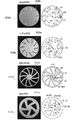
- 11 to 28 show examples of the shapes of the opposing pieces applied in the fifth modification.
- 11 to 22 show the amplitude of vibration of the vibrating device 10 in the case where the counterparts shown in FIGS. 11 to 22 are applied to the rotating device 1 described with reference to FIGS. ), the measurement result of the rotational speed of the opposing piece is shown.
- the reference numerals to which "a" is added to the reference numerals are the reference characters for the parallel regions
- the reference characters to which "b” is added are the reference characters for the three-dimensional shape.
- a parallel region 601a and a three-dimensional shape 601b are formed on the opposing surface of the opposing member 601 .
- the material of the opposing member used for the measurement shown in the explanation of Modified Example 5 below is made of aluminum, and the opposing surface is has a diameter of 40 mm and a thickness of 2.5 mm. Moreover, when grooves are provided on the facing surface, the depth of the grooves is 1.5 mm.
- the outer peripheral shape of the opposing surface of the opposing element 601 shown in FIG. 11 is circular, like the vibrating surface of the vibrator described above. Further, the facing surface is formed so that its end faces the end of the vibration surface. For example, the outer circumference of the facing surface and the outer circumference of the vibrating surface are formed to have the same shape and size.
- the opposing surface of the opposing piece 601 has a parallel region 601a and a plurality of three-dimensional shapes 601b.
- the opposing member 601 has a hole, which is a three-dimensional shape 601b, formed at the end of the opposing surface.
- the opposing piece 601 has an open end by forming a hole, which is a three-dimensional shape 601b, at the end of the opposing surface. That is, the three-dimensional shape 601b formed on the opposing member 601 forms a slit on the opposing surface.
- the three-dimensional shape 601b formed on the opposing surface is formed along a plurality of radial curves extending from the center to the end of the opposing surface.
- the distance from the outer circumference of the radial curve to the center of the curvature circle of the radial curve is, for example, 21 mm, although not limited.
- the width of the three-dimensional shape 601b in the short direction is, for example, 2 mm.
- the distance from the outer periphery of the radial curve to the center of the curvature circle of the radial curve and the width in the lateral direction of the three-dimensional shape are the same as those shown in FIG. may be the same as the example shown in
- the above-described parallel region is formed in the central portion of the opposing surface.
- the outer periphery of the parallel region is formed so as to define a concentric circle with the outer periphery of the opposing surface.
- the three-dimensional shape 601b (or the end portion of the three-dimensional shape 601b) formed on the opposing surface of the opposing member 601 is formed along a concentric circle that is concentric with the outer circumference of the opposing surface.
- the radius of the outer circumference of the parallel region is 27 mm.
- the radius of the outer circumference circle of the parallel region formed at the center of the facing surface may be 60% to 80% of the radius of the outer circumference circle of the facing surface. More preferably, the radius of the outer circumference of the parallel region may be 70% to 80% of the radius of the outer circumference of the opposing surface.
- the three-dimensional shape 601b is formed along a plurality of radial curves extending from the center to the end of the opposing surface.
- adjacent three-dimensional shapes 601b are not symmetrical to each other with respect to the radial direction of the facing surfaces. That is, the plurality of three-dimensional shapes 601b formed on the opposing surface includes a plurality of adjacent three-dimensional shapes 601b that are not symmetrical with respect to the radial direction of the opposing surface.
- a hole may be formed in the central portion of the facing surface instead of the parallel region.
- the opposing surface of the opposing piece 602 shown in FIG. 12 has a parallel region 602a and a plurality of three-dimensional shapes 602b.
- the three-dimensional shape 602b formed on the opposing surface is formed along a plurality of radial curves extending from the center to the end of the opposing surface.
- the distance from the outer circumference of the radial curve to the center of the curvature circle of the radial curve is, but not limited to, 16 mm, for example.
- Other configurations of the counterpart 602 are the same as those of the counterpart 601 .
- the opposing surface of the opposing piece 603 shown in FIG. 13 has a parallel region 603a and a plurality of three-dimensional shapes 603b.
- the three-dimensional shape 603b is formed with holes and grooves.
- the three-dimensional shape 603b is formed of holes along a plurality of radial curves extending from the center to the end of the facing surface, but the three-dimensional shape 603b is formed of grooves at the outer peripheral edge of the facing surface. .
- the opposing surface of the opposing member 603 is not formed with a slit.
- a circular parallel region is formed at the center of the facing surface.
- the circular diameter is, but is not limited to, 6.5 mm.
- the three-dimensional shape 603b is formed along a plurality of radial curves extending from the center to the end of the facing surface.
- the distance (curvature radius) from the outer circumference of the radial curve to the center of the curvature circle of the radial curve is not limited, but is, for example, 20 mm.
- the radius of curvature may be the same in the opposing members described with reference to FIGS. 14 to 22 .
- the three-dimensional shape 604b is formed by grooves.
- the three-dimensional shape 604b is formed along a plurality of radial curves extending from the center to the end of the facing surface.
- the three-dimensional shape 605b is formed by holes.
- the three-dimensional shape 605b is formed along a plurality of radial curves extending from the center to the end of the opposing surface, but the three-dimensional shape 605b is not formed on the outer peripheral edge of the opposing surface.
- the three-dimensional shape 606b is formed by grooves.
- the three-dimensional shape is formed along a plurality of radial curves extending from the center to the end of the facing surface, but the three-dimensional shape is not formed on the outer peripheral edge of the facing surface.
- the three-dimensional shape 607b is formed by grooves and holes.
- the three-dimensional shape 607b is formed by grooves along a plurality of radial curves extending from the center to the end of the facing surface, but the three-dimensional shape 607b is not formed on the outer peripheral edge of the facing surface.
- a three-dimensional shape 607b is formed in a circular shape with a hole in the center of the facing surface.
- the three-dimensional shape 608b is formed with holes and grooves.
- the three-dimensional shape 608b is formed of holes along a plurality of radial curves extending from the center to the end of the facing surface, but the three-dimensional shape 608b is formed of grooves at the outer peripheral edge of the facing surface. .
- the opposing member 608 does not have a parallel region at the center of the opposing surface.
- the three-dimensional shape 609b is formed with grooves.
- the three-dimensional shape 609b is formed by grooves along a plurality of radial curves extending from the center to the end of the facing surface.
- the three-dimensional shape 610b is formed with holes and grooves.
- the three-dimensional shape 610b is formed by grooves along a plurality of radial curves extending from the center to the end of the facing surface.
- a three-dimensional shape 610b is formed in a circular shape with a hole at the center of the facing surface.
- the three-dimensional shape 611b is formed by holes.
- the three-dimensional shape 611b is formed by holes along a plurality of radial curves extending from the center to the end of the facing surface.
- the three-dimensional shape 611b is not formed on the outer peripheral edge of the facing surface.
- a circular parallel region is provided in the central portion of the facing surface.
- the three-dimensional shape 612b is formed by grooves.
- the three-dimensional shape 612b is formed by grooves along a plurality of radial curves extending from the center to the end of the facing surface.
- the three-dimensional shape 612b is not formed on the outer peripheral edge of the facing surface.
- a circular parallel region 612a is provided at the center of the facing surface.
- FIGS. 23 to 28 the left side is a photographic view of the opposing piece, and the right side is a schematic view.
- the black three-dimensional shapes shown in the photograph are holes, and the other three-dimensional shapes are grooves.
- adjacent three-dimensional shapes are formed symmetrically with respect to the radial direction of the opposing surfaces.
- the difference between the opposing members 615 and 624 is that the three-dimensional shape of the opposing member 615 is formed of holes, while the three-dimensional shape 624b of the opposing member 624 is formed of grooves.
- the opposing surface of the opposing piece 626 has a parallel region 626a and a plurality of three-dimensional shapes 626b.
- the three-dimensional shape 626b formed by the groove is formed with a wider area than the other opposing members such as the opposing members 601 to 612.
- the central portion of the opposing surface of the opposing element 626 is formed in a substantially circular shape.
- the facing surface of the opposing member 627 also has a three-dimensional shape 627b with a large area.
- the opposing surface of the opposing member 627 is different from the opposing member 626 in that it has a three-dimensional shape with a hole at the center.
- the opposing surface of the opposing piece 628 has a parallel region 628a and a plurality of three-dimensional shapes 628b.
- the three-dimensional shape 628b is formed by convex portions.
- the opposing surface of the opposing piece 629 has a parallel region 629a and a plurality of three-dimensional shapes 629b.
- the three-dimensional shape 629b is formed by a plurality of holes.
- the three-dimensional shape 629b may be formed by multiple grooves or by a combination of holes and grooves.
- Opponent 631 is an opponent that is also used in modification 6, which will be described later. In Modified Example 5, rotation of the opposing piece 631 was confirmed.
- the outer peripheral shape of the opposing surface of the opposing member 633 is rectangular.
- the outer peripheral shape of the facing surface of the opposing element 633 is different from the outer peripheral shape of the vibrating surface of the vibrator. Therefore, the opposing surface of the opposing element 633 is not formed so that its end faces the end of the vibration surface. As described above, clear rotation of the opposing piece 633 could not be confirmed.
- the opposing surface of the opposing member 634 has a parallel region 634a and a three-dimensional shape 634b.
- the three-dimensional shape 634b is formed along a spiral curve extending from the center of the facing surface of the opposing member 634 toward the end.
- the three-dimensional shape 634b may be an Archimedean spiral shape. In this case, although not limited, the width of the three-dimensional shape 634b in the lateral direction may be 5 mm.
- One three-dimensional shape is formed on the opposing surface of the opposing member 634 . Rotation of the counterpiece 634 was confirmed as described above.
- Modification 5 is an example in which an opposing member having a three-dimensional shape other than an impeller shape is applied to the rotating device 1 described with reference to FIGS. example) was explained.
- Modified Example 6 an example will be described in which an opposing member having a three-dimensional shape other than an impeller shape is rotated in the air.
- Modification 6 is the same as Modification 3 except that a counterpiece different from that in Modification 3 is used.
- a rotating device the rotating device 1 described with reference to FIG. 9A is used.
- the opposing member has a facing surface facing the vibrating surface of the vibrator, and the facing surface includes a parallel region facing the vibrating surface of the vibrator in parallel and an end portion of the facing surface. It has a plurality of three-dimensional shapes formed so as to extend toward. That is, the vibrating surface and the facing surface may each have parallel regions facing each other in parallel. Also, the parallel region may be a plane.
- the starting point for forming the three-dimensional shape extending toward the end of the facing surface may be the inner side of the facing surface, particularly the central portion of the facing surface. That is, the three-dimensional shape may be formed from the inner side of the facing surface or from the central portion of the inner side of the facing surface toward the end portion of the facing surface.
- the parallel region is the region where the levitation force (that is, the repulsive force between the opposing surface and the vibration surface) is considered to occur between the vibration surface of the vibrator and the vibrator due to the squeeze film effect described above in the air. is.
- the three-dimensional shape is a region that is considered to generate a rotational force of the opposing piece under the action of the fluid.
- FIGS. 29 and 30 show opposing members 701 to 708 as examples of shapes of opposing members applied in the sixth modification.
- the manufacturing method of the counter element in Modification 6 is not limited, the counter elements shown in FIGS. 29 and 30 are made of ABS resin and manufactured using a 3D printer.
- the reference numerals to which "a" is added to the reference numerals are the reference characters for the parallel regions, and the reference characters to which "b" is added are the reference characters for the three-dimensional shape.
- a parallel region 701a and a three-dimensional shape 701b are formed on the opposing surface of the opposing member 701 .
- the opposing surface of the opposing member 701 has a parallel region 701a and a three-dimensional shape 702b.
- the parallel region 701a has a central portion 701a1, beams 701a2, and an outer peripheral portion 701a3.
- the central portion 701a1 is the area of the central portion of the facing surface.
- the outer peripheral portion 701a3 is a region of the outer peripheral portion of the facing surface.
- the beam 701a2 is a region that connects the central portion 701a1 and the outer peripheral portion 701a3.
- the three-dimensional shape 702b is formed by holes.
- Opponents 702 to 708 also have parallel regions and three-dimensional shapes.
- the parallel region has a central portion, a beam, and an outer peripheral portion.
- the opposing members 701 to 708 have different numbers of beams, and the number of beams is two to nine.
- the two side surfaces connecting the central portion of the facing surface and the outer peripheral portion may or may not be parallel to each other. If not parallel, for example, the angle formed by the intersection of the two longitudinal sides of the beam 704a2 of the opposing member 704 is 10°. Also, the diameter of the central portion 704a1 of the opposing piece 704 is 10.5 mm. The diameter of the outer circumference of the outer circumference 704a3 of the counter piece 704 is 40 mm, and the diameter of the inner circumference is 30 mm.
- FIG. 31 shows the relationship between the number of beams, the mass, the area of the holes, and the ratio of the area of the holes to the whole of the opposing member shown in FIG.
- FIG. 32 shows the relationship between the number of beams of the opposing member shown in FIG. 29, the ratio of the hole area to the whole, the rotating speed of the opposing member, and the rear end amplitude of the vibrator.
- FIG. 33 shows the relationship between the number of beams of the opposing piece shown in FIG. 29 and the rotational speed. According to FIGS. 32 and 33, the rotational speed of the opposing member having six beams (that is, the opposing member 708) is faster than the other opposing members.
- a motor having the rotation device 1 in the above embodiment and the above modification may be configured.
- the motor may be driven by rotating the counterpart.
- a pump having the rotating device 1 in the above embodiment and the above modified example may be constructed, and the pump may be driven by rotating the counterpiece.
- the rotating device 1 may provide the function of a pump by sucking the fluid through the through holes provided in the vibrating device of the rotating device 1 and sending the fluid out of the vibrating device.
- the counter 20 of the rotating device 1 in the above embodiment is configured to rotate around the vibration direction of the vibrating device 10, as a modification, the counter 20 may be fixed so as not to rotate. good.
- the counter 20 may be fixed so as not to rotate. good.
- the said opposing surface may space apart and may oppose.
- fixing may mean that the counterpart 20 does not rotate at a predetermined position and is immovable.
- the counterpart 20 may be fixed, for example, via a support member or by being integrally formed with a fixed member. By fixing the opposing member 20, the position of the center portion of the vibration surface and the position of the center portion of the surface portion of the opposing member 20 may be located close to each other.
- the distance between the vibration surface and the counter surface is not limited, but may be set to 10 to 500 microns.
- the vibrating surface and the facing surface may have the same shape (for example, circular).
- a pump having the rotating device in the modification may be configured.
- the pump may be formed, for example, by providing a vibrating device with a through hole, as in the example of FIG. 8A.
Landscapes
- Engineering & Computer Science (AREA)
- Mechanical Engineering (AREA)
- General Engineering & Computer Science (AREA)
- Structures Of Non-Positive Displacement Pumps (AREA)
- Apparatuses For Generation Of Mechanical Vibrations (AREA)
- Reciprocating Pumps (AREA)
- General Electrical Machinery Utilizing Piezoelectricity, Electrostriction Or Magnetostriction (AREA)
Priority Applications (4)
| Application Number | Priority Date | Filing Date | Title |
|---|---|---|---|
| JP2023545166A JP7672738B2 (ja) | 2021-08-30 | 2022-07-28 | 回転装置、モータ、及びポンプ |
| CN202280058108.9A CN117882290A (zh) | 2021-08-30 | 2022-07-28 | 旋转装置、马达、以及泵 |
| US18/590,487 US20240200575A1 (en) | 2021-08-30 | 2024-02-28 | Rotating apparatus, motor, and pump |
| JP2025067208A JP2025096587A (ja) | 2021-08-30 | 2025-04-16 | 回転装置、モータ、及びポンプ |
Applications Claiming Priority (4)
| Application Number | Priority Date | Filing Date | Title |
|---|---|---|---|
| JP2021-140218 | 2021-08-30 | ||
| JP2021140218 | 2021-08-30 | ||
| JP2022026548 | 2022-02-24 | ||
| JP2022-026548 | 2022-02-24 |
Related Child Applications (1)
| Application Number | Title | Priority Date | Filing Date |
|---|---|---|---|
| US18/590,487 Continuation US20240200575A1 (en) | 2021-08-30 | 2024-02-28 | Rotating apparatus, motor, and pump |
Publications (1)
| Publication Number | Publication Date |
|---|---|
| WO2023032539A1 true WO2023032539A1 (ja) | 2023-03-09 |
Family
ID=85411208
Family Applications (1)
| Application Number | Title | Priority Date | Filing Date |
|---|---|---|---|
| PCT/JP2022/029181 Ceased WO2023032539A1 (ja) | 2021-08-30 | 2022-07-28 | 回転装置、モータ、及びポンプ |
Country Status (3)
| Country | Link |
|---|---|
| US (1) | US20240200575A1 (https=) |
| JP (2) | JP7672738B2 (https=) |
| WO (1) | WO2023032539A1 (https=) |
Citations (3)
| Publication number | Priority date | Publication date | Assignee | Title |
|---|---|---|---|---|
| JPH05207762A (ja) * | 1992-01-27 | 1993-08-13 | Olympus Optical Co Ltd | 超音波モータ |
| JPH1146485A (ja) * | 1997-07-25 | 1999-02-16 | Asmo Co Ltd | 超音波モータ及びロータ |
| JP2014005758A (ja) * | 2012-06-22 | 2014-01-16 | Olympus Corp | ポンプ装置 |
Family Cites Families (11)
| Publication number | Priority date | Publication date | Assignee | Title |
|---|---|---|---|---|
| EP0356591B1 (en) * | 1988-09-02 | 1995-11-15 | Honda Electronic Co., Ltd. | Ultrasonic driving devices |
| JPH02119984U (https=) * | 1989-03-15 | 1990-09-27 | ||
| JPH02312591A (ja) * | 1989-05-26 | 1990-12-27 | Chisso Corp | 超音波による酵素反応の制御法 |
| JP3295850B2 (ja) * | 1991-10-29 | 2002-06-24 | スターライト工業株式会社 | 超音波モータ |
| JP2868679B2 (ja) * | 1992-11-27 | 1999-03-10 | アルプス電気株式会社 | 流体攪拌器 |
| JP4109925B2 (ja) * | 2002-08-06 | 2008-07-02 | セイコーインスツル株式会社 | 圧電アクチュエータ及び圧電アクチュエータ付き電子機器 |
| JP4930906B2 (ja) * | 2007-12-20 | 2012-05-16 | 国立大学法人 新潟大学 | 磁気浮上回転装置 |
| JP5676865B2 (ja) * | 2009-09-24 | 2015-02-25 | 中野 紘二 | 混合装置 |
| JP2011109787A (ja) | 2009-11-17 | 2011-06-02 | Nikon Corp | 振動アクチュエータ、レンズ鏡筒及びカメラ |
| JP7076282B2 (ja) * | 2018-05-11 | 2022-05-27 | 株式会社日立ハイテク | 撹拌装置、分析装置、分注方法 |
| CN112448613B (zh) * | 2020-10-26 | 2021-11-23 | 南京航空航天大学 | 一种贴片式压电驱动的水下螺旋桨矢量推进系统及其方法 |
-
2022
- 2022-07-28 JP JP2023545166A patent/JP7672738B2/ja active Active
- 2022-07-28 WO PCT/JP2022/029181 patent/WO2023032539A1/ja not_active Ceased
-
2024
- 2024-02-28 US US18/590,487 patent/US20240200575A1/en active Pending
-
2025
- 2025-04-16 JP JP2025067208A patent/JP2025096587A/ja active Pending
Patent Citations (3)
| Publication number | Priority date | Publication date | Assignee | Title |
|---|---|---|---|---|
| JPH05207762A (ja) * | 1992-01-27 | 1993-08-13 | Olympus Optical Co Ltd | 超音波モータ |
| JPH1146485A (ja) * | 1997-07-25 | 1999-02-16 | Asmo Co Ltd | 超音波モータ及びロータ |
| JP2014005758A (ja) * | 2012-06-22 | 2014-01-16 | Olympus Corp | ポンプ装置 |
Also Published As
| Publication number | Publication date |
|---|---|
| JP7672738B2 (ja) | 2025-05-08 |
| JPWO2023032539A1 (https=) | 2023-03-09 |
| JP2025096587A (ja) | 2025-06-26 |
| US20240200575A1 (en) | 2024-06-20 |
Similar Documents
| Publication | Publication Date | Title |
|---|---|---|
| CN108025333B (zh) | 非平面和非对称压电晶体及反射器 | |
| JP5020962B2 (ja) | 円盤状の切削工具及び切削装置 | |
| CN102823006B (zh) | 具有匹配的转换器和安装板的兆声波多频装置 | |
| CN102459900A (zh) | 流体盘形泵 | |
| CN1047873C (zh) | 超声波转换器 | |
| Koyama et al. | An ultrasonically levitated noncontact stage using traveling vibrations on precision ceramic guide rails | |
| Saito et al. | Resonant mode design for noncontact ultrasonic motor with levitated rotor | |
| WO2023032539A1 (ja) | 回転装置、モータ、及びポンプ | |
| Shi et al. | Performance evaluation of a novel disk-type motor using ultrasonic levitation: Modeling and experimental validation | |
| CN102312822A (zh) | 一种旋转行波无阀压电驱动泵 | |
| JPH05176564A (ja) | 放射圧を利用したアクチュエータ | |
| CN117882290A (zh) | 旋转装置、马达、以及泵 | |
| JP2008212916A (ja) | 超音波複合振動装置 | |
| Koyama et al. | A stator for a self-running, ultrasonically-levitated sliding stage | |
| Hirose et al. | A small noncontact ultrasonic motor | |
| Sun et al. | Particle Trapping and Transportation with MEMS Zeroth-order Bessel Beam Acoustic Transducer (BBAT) | |
| Hu et al. | New type of linear ultrasonic actuator based on a plate-shaped vibrator with triangular grooves | |
| Yamayoshi et al. | Sound field characteristics in air gaps of noncontact ultrasonic motor driven by two flexural standing wave vibration disks | |
| CN102240189B (zh) | 驻波型超声吸尘器及其吸尘方法 | |
| Yamayoshi et al. | Noncontact ultrasonic motor with two flexural standing wave vibration disks | |
| Yamayoshi et al. | Optimum design for noncontact ultrasonic motor with flexurally vibrating disk using an equivalent circuit considering viscosity of air | |
| Lee et al. | Vortex-Beam Acoustic Transducer for Underwater Propulsion | |
| Sadayuki | Phenomena, theory and applications of near-field acoustic levitation | |
| JP6419554B2 (ja) | ポンプ及びこのポンプに用いるポンプ用対向子 | |
| JP3575569B2 (ja) | ロータ浮揚式超音波モータ |
Legal Events
| Date | Code | Title | Description |
|---|---|---|---|
| 121 | Ep: the epo has been informed by wipo that ep was designated in this application |
Ref document number: 22864127 Country of ref document: EP Kind code of ref document: A1 |
|
| WWE | Wipo information: entry into national phase |
Ref document number: 202280058108.9 Country of ref document: CN |
|
| WWE | Wipo information: entry into national phase |
Ref document number: 2023545166 Country of ref document: JP |
|
| NENP | Non-entry into the national phase |
Ref country code: DE |
|
| 122 | Ep: pct application non-entry in european phase |
Ref document number: 22864127 Country of ref document: EP Kind code of ref document: A1 |