WO2023032390A1 - 銅合金線、被覆電線、端子付き電線、及び銅合金線の製造方法 - Google Patents
銅合金線、被覆電線、端子付き電線、及び銅合金線の製造方法 Download PDFInfo
- Publication number
- WO2023032390A1 WO2023032390A1 PCT/JP2022/022895 JP2022022895W WO2023032390A1 WO 2023032390 A1 WO2023032390 A1 WO 2023032390A1 JP 2022022895 W JP2022022895 W JP 2022022895W WO 2023032390 A1 WO2023032390 A1 WO 2023032390A1
- Authority
- WO
- WIPO (PCT)
- Prior art keywords
- copper alloy
- wire
- mass
- less
- alloy wire
- Prior art date
- Legal status (The legal status is an assumption and is not a legal conclusion. Google has not performed a legal analysis and makes no representation as to the accuracy of the status listed.)
- Ceased
Links
Images





Classifications
-
- H—ELECTRICITY
- H01—ELECTRIC ELEMENTS
- H01B—CABLES; CONDUCTORS; INSULATORS; SELECTION OF MATERIALS FOR THEIR CONDUCTIVE, INSULATING OR DIELECTRIC PROPERTIES
- H01B5/00—Non-insulated conductors or conductive bodies characterised by their form
- H01B5/02—Single bars, rods, wires, or strips
-
- H—ELECTRICITY
- H01—ELECTRIC ELEMENTS
- H01B—CABLES; CONDUCTORS; INSULATORS; SELECTION OF MATERIALS FOR THEIR CONDUCTIVE, INSULATING OR DIELECTRIC PROPERTIES
- H01B1/00—Conductors or conductive bodies characterised by the conductive materials; Selection of materials as conductors
- H01B1/02—Conductors or conductive bodies characterised by the conductive materials; Selection of materials as conductors mainly consisting of metals or alloys
- H01B1/026—Alloys based on copper
-
- C—CHEMISTRY; METALLURGY
- C22—METALLURGY; FERROUS OR NON-FERROUS ALLOYS; TREATMENT OF ALLOYS OR NON-FERROUS METALS
- C22C—ALLOYS
- C22C9/00—Alloys based on copper
-
- C—CHEMISTRY; METALLURGY
- C22—METALLURGY; FERROUS OR NON-FERROUS ALLOYS; TREATMENT OF ALLOYS OR NON-FERROUS METALS
- C22C—ALLOYS
- C22C9/00—Alloys based on copper
- C22C9/02—Alloys based on copper with tin as the next major constituent
-
- C—CHEMISTRY; METALLURGY
- C22—METALLURGY; FERROUS OR NON-FERROUS ALLOYS; TREATMENT OF ALLOYS OR NON-FERROUS METALS
- C22F—CHANGING THE PHYSICAL STRUCTURE OF NON-FERROUS METALS AND NON-FERROUS ALLOYS
- C22F1/00—Changing the physical structure of non-ferrous metals or alloys by heat treatment or by hot or cold working
- C22F1/08—Changing the physical structure of non-ferrous metals or alloys by heat treatment or by hot or cold working of copper or alloys based thereon
-
- H—ELECTRICITY
- H01—ELECTRIC ELEMENTS
- H01B—CABLES; CONDUCTORS; INSULATORS; SELECTION OF MATERIALS FOR THEIR CONDUCTIVE, INSULATING OR DIELECTRIC PROPERTIES
- H01B1/00—Conductors or conductive bodies characterised by the conductive materials; Selection of materials as conductors
- H01B1/02—Conductors or conductive bodies characterised by the conductive materials; Selection of materials as conductors mainly consisting of metals or alloys
-
- H—ELECTRICITY
- H01—ELECTRIC ELEMENTS
- H01B—CABLES; CONDUCTORS; INSULATORS; SELECTION OF MATERIALS FOR THEIR CONDUCTIVE, INSULATING OR DIELECTRIC PROPERTIES
- H01B13/00—Apparatus or processes specially adapted for manufacturing conductors or cables
-
- H—ELECTRICITY
- H01—ELECTRIC ELEMENTS
- H01B—CABLES; CONDUCTORS; INSULATORS; SELECTION OF MATERIALS FOR THEIR CONDUCTIVE, INSULATING OR DIELECTRIC PROPERTIES
- H01B13/00—Apparatus or processes specially adapted for manufacturing conductors or cables
- H01B13/0016—Apparatus or processes specially adapted for manufacturing conductors or cables for heat treatment
-
- H—ELECTRICITY
- H01—ELECTRIC ELEMENTS
- H01B—CABLES; CONDUCTORS; INSULATORS; SELECTION OF MATERIALS FOR THEIR CONDUCTIVE, INSULATING OR DIELECTRIC PROPERTIES
- H01B7/00—Insulated conductors or cables characterised by their form
-
- H—ELECTRICITY
- H01—ELECTRIC ELEMENTS
- H01B—CABLES; CONDUCTORS; INSULATORS; SELECTION OF MATERIALS FOR THEIR CONDUCTIVE, INSULATING OR DIELECTRIC PROPERTIES
- H01B7/00—Insulated conductors or cables characterised by their form
- H01B7/0009—Details relating to the conductive cores
-
- H—ELECTRICITY
- H01—ELECTRIC ELEMENTS
- H01B—CABLES; CONDUCTORS; INSULATORS; SELECTION OF MATERIALS FOR THEIR CONDUCTIVE, INSULATING OR DIELECTRIC PROPERTIES
- H01B7/00—Insulated conductors or cables characterised by their form
- H01B7/02—Disposition of insulation
Definitions
- the present disclosure relates to a copper alloy wire, a coated wire, a terminal-equipped wire, and a method for producing a copper alloy wire.
- This application claims priority based on Japanese Patent Application No. 2021-141928 filed in Japan on August 31, 2021, and incorporates all the contents described in the Japanese application.
- Patent Documents 1 and 2 disclose a thin wire made of a copper alloy containing iron, phosphorus, and tin in specific ranges and having a wire diameter of 0.5 mm or less.
- the fine wires are used as conductors of covered electric wires.
- the conductor is, for example, a stranded wire formed by twisting a plurality of thin wires.
- the copper alloy wire according to the present disclosure is A wire made of a copper alloy, Tensile strength is 400 MPa or more, Breaking elongation is 5% or more, Conductivity is 60% IACS or more, The wire diameter is 0.5 mm or less, The copper alloy contains 0.05% to 1.6% by mass of iron, 0.01% to 0.7% by mass of phosphorus, and 0.05% to 0.7% by mass of tin. , the balance is a composition consisting of copper and inevitable impurities, The structure of the copper alloy contains crystals, The grain size difference obtained from the difference between the maximum grain size and the minimum grain size in a cross section is 1.0 ⁇ m or less.
- a method for manufacturing a copper alloy wire includes: A first step of producing a cast material made of a copper alloy by a continuous casting method; A second step of manufacturing a linear extruded material by subjecting the cast material to conform extrusion; A third step of manufacturing a drawn wire material by subjecting the extruded material to a drawing process; A fourth step of manufacturing a heat-treated material by subjecting the drawn wire material to a heat treatment,
- the copper alloy contains 0.05% to 1.6% by mass of iron, 0.01% to 0.7% by mass of phosphorus, and 0.05% to 0.7% by mass of tin.
- the balance is a composition consisting of copper and inevitable impurities
- the area reduction rate of the conform extrusion is 50% or more
- the temperature of the extruded material immediately after conform extrusion is 350 ° C. or higher
- the temperature of the heat treatment is 350° C. or higher.
- FIG. 1 is a schematic perspective view showing an example of a copper alloy wire of an embodiment.
- FIG. 2 is a sectional view taken along line II-II of FIG.
- FIG. 3 is a diagram for explaining a method of measuring the average crystal grain size.
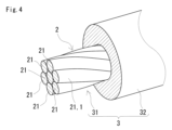
- FIG. 4 is an example of the covered electric wire of the embodiment, and is a schematic perspective view showing a covered electric wire provided with the copper alloy stranded wire of the embodiment as a conductor.
- FIG. 5 is a schematic configuration diagram showing an example of the terminal-equipped electric wire of the embodiment.
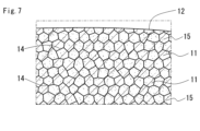
- FIG. 6 is a diagram illustrating an example of a conform extruder used in the copper alloy wire manufacturing method of the embodiment. 7 shows sample No. 1 of Test Example 1.
- FIG. 1 is a schematic perspective view showing an example of a copper alloy wire of an embodiment.
- FIG. 2 is a sectional view taken along line II-II of FIG.
- FIG. 3 is a diagram for explaining a method of measuring the average crystal grain size.
- FIG. 4 is
- FIG. 1 is a schematic diagram showing an enlarged part of a cross section of the copper alloy wire of 1-1.
- FIG. FIG. 8 shows sample No. 1 of Test Example 1.
- 1 is a schematic diagram showing an enlarged part of a cross section of a 1-102 copper alloy wire.
- a copper alloy wire having a good balance between strength and elongation is desired.
- the copper alloy wires described in Patent Documents 1 and 2 are excellent in strength because they are made of the copper alloy having the specific composition described above. Although further improvement in strength is desired, elongation may decrease with the improvement in strength.
- a copper alloy wire that is excellent in manufacturability is desirable.
- the manufacturing process of the fine wire described above typically includes a step of drawing a thick material and a step of heat-treating the drawn wire, as described in Patent Documents 1 and 2.
- a thick material is, for example, a cast material.
- a cast material made of a copper alloy having the specific composition described above may have a structure in which compounds containing iron and phosphorus are unevenly distributed. If a thick material in which the above compound is unevenly distributed is subjected to wire drawing, wire breakage due to the above compound is likely to occur during wire drawing. Wire breakage lowers the productivity of drawn wire rods and, in turn, the productivity of thin wire rods.
- One of the purposes of the present disclosure is to provide a copper alloy wire that has well-balanced strength and elongation.
- Another object of the present disclosure is to provide a method for manufacturing a copper alloy wire that can produce a copper alloy wire having a good balance of strength and elongation with good productivity.
- the copper alloy wire of the present disclosure has strength and elongation in good balance.
- the method for producing a copper alloy wire of the present disclosure can produce a copper alloy wire having strength and elongation in a well-balanced manner with good productivity.
- a copper alloy wire according to one aspect of the present disclosure A wire made of a copper alloy, Tensile strength is 400 MPa or more, Breaking elongation is 5% or more, Conductivity is 60% IACS or more, The wire diameter is 0.5 mm or less, The copper alloy contains 0.05% to 1.6% by mass of iron, 0.01% to 0.7% by mass of phosphorus, and 0.05% to 0.7% by mass of tin. , the balance is a composition consisting of copper and inevitable impurities, The structure of the copper alloy contains crystals, The grain size difference obtained from the difference between the maximum grain size and the minimum grain size in a cross section is 1.0 ⁇ m or less.
- a cross section is a cross section obtained by cutting a long material such as a copper alloy wire or an extruded material described later on a plane perpendicular to the longitudinal direction of the long material.
- Wire diameter in the present disclosure is the diameter of a circle having the same area as the cross-sectional area of the copper alloy wire.
- the cross-sectional area of the copper alloy wire is the cross-sectional area of the copper alloy wire.
- a structure with a crystal grain size difference of 1.0 ⁇ m or less has uniform crystal sizes compared to a structure with a crystal grain size difference of more than 1.0 ⁇ m.
- the copper alloy wire of the present disclosure has a crystal structure with a uniform size, so that the mechanical properties due to the variation in crystal size are lower than when the crystal structure has a non-uniform size. decrease is unlikely to occur. Therefore, the copper alloy wire of the present disclosure has high tensile strength and high elongation at break in good balance. From this point, the copper alloy wire of the present disclosure has strength and elongation in good balance. Additionally, the copper alloy wire of the present disclosure has a conductivity of 60% IACS or greater. Such a copper alloy wire of the present disclosure can be suitably used as a conductor of a covered electric wire.
- the copper alloy wire of the present disclosure can be manufactured with good productivity by the method of manufacturing the copper alloy wire of the present disclosure, which will be described later. From this point, the copper alloy wire of the present disclosure is also excellent in manufacturability.
- the composition of the copper alloy may contain less than 0.001% by mass of carbon.
- the above copper alloy wire has high tensile strength as described above even if it does not contain carbon substantially. In the manufacturing process, carbon is not required as a raw material for the copper alloy wire.
- the above copper alloy wire is superior in manufacturability because it does not require a step of adding carbon or the like.
- the content ratio of iron to phosphorus may be 1.0 or more and 30 or less in mass ratio.
- a copper alloy wire with a content of 1.0 or more has excellent strength.
- a copper alloy wire with a content ratio of 30 or less is less likely to suffer deterioration in mechanical properties due to variations in crystal size.
- the copper alloy wire according to any one of (1) to (3) above may have a work hardening index of 0.1 or more.
- a copper alloy wire having a work hardening index of 0.1 or more is easily work hardened, so it is suitable as a conductor for an electric wire with a terminal, which will be described later.
- a coated wire according to an aspect of the present disclosure includes a conductor and an insulating layer covering the outer periphery of the conductor, the conductor includes a copper alloy stranded wire, and the copper alloy stranded wire is the above (1 ) to (4).
- the copper alloy stranded wire described above includes the copper alloy wire of the present disclosure, it has strength and elongation in a well-balanced manner.
- the above copper alloy stranded wire is superior in resistance to repeated bending and resistance to impact as compared with a single copper alloy wire.
- the copper alloy stranded wire described above includes the copper alloy wire of the present disclosure, it is also excellent in electrical conductivity.
- Such a copper alloy stranded wire can be suitably used as a conductor of a covered electric wire.
- the covered electric wire of the present disclosure includes the copper alloy stranded wire as a conductor, it has strength and elongation in a well-balanced manner. In addition, the covered electric wire of the present disclosure is excellent in resistance to repeated bending and resistance to impact. Furthermore, since the coated electric wire of the present disclosure includes the copper alloy stranded wire as a conductor, it also has excellent conductivity.
- An electric wire with a terminal includes the covered electric wire of (5) above and a terminal attached to at least one end of the covered electric wire.
- the electric wire with terminal of the present disclosure includes the copper alloy stranded wire as a conductor of the covered electric wire, it has strength and elongation in a well-balanced manner.
- the electric wire with terminal of the present disclosure is excellent in resistance to repeated bending and resistance to impact.
- the electric wire with a terminal of the present disclosure includes the copper alloy stranded wire as a conductor of the covered electric wire, it is also excellent in conductivity.
- a method for manufacturing a copper alloy wire includes: A first step of producing a cast material made of a copper alloy by a continuous casting method; A second step of manufacturing a linear extruded material by subjecting the cast material to conform extrusion; A third step of manufacturing a drawn wire material by subjecting the extruded material to a drawing process; A fourth step of manufacturing a heat-treated material by subjecting the drawn wire material to a heat treatment,
- the copper alloy contains 0.05% to 1.6% by mass of iron, 0.01% to 0.7% by mass of phosphorus, and 0.05% to 0.7% by mass of tin.
- the balance is a composition consisting of copper and inevitable impurities
- the area reduction rate of the conform extrusion is 50% or more
- the temperature of the extruded material immediately after conform extrusion is 350 ° C. or higher
- the temperature of the heat treatment is 350° C. or higher.
- the area reduction rate of conform extrusion is the ratio obtained by dividing the difference between the cross-sectional area of the cast material and the cross-sectional area of the extruded material by the cross-sectional area of the cast material, and is expressed as a percentage (%).
- the cross-sectional area of the casting is the cross-sectional area of the casting.
- the cross-sectional area of the extrusion is the cross-sectional area of the extrusion.
- the temperature of the extruded material immediately after conform extrusion is the surface temperature of the extruded material at the following points. The above point is a point 50 mm in the longitudinal direction of the extruded material from the discharge part of the extruded material in the conform extruder.
- the copper alloy wire production method of the present disclosure can produce a copper alloy wire having a good balance between strength and elongation. Furthermore, the produced copper alloy wire is also excellent in electrical conductivity.
- the copper alloy wire manufacturing method of the present disclosure can reduce the variation in crystal size with respect to the structure of the copper alloy that constitutes the copper alloy wire.
- the method for producing a copper alloy wire of the present disclosure provides a copper alloy wire having a tensile strength of 400 MPa or more and an elongation at break of 5% or more, and having the crystal grain size difference of 1.0 ⁇ m or less. can be manufactured. Furthermore, this copper alloy wire has a conductivity of 60% IACS or higher.
- the method for manufacturing a copper alloy wire of the present disclosure can relatively increase the casting speed (m/min) in the first step.
- the higher the casting speed the more efficiently the cast material is mass-produced.
- the second step can produce long extrusions. That is, extruded materials can also be mass-produced.
- wire breakage is less likely to occur during wire drawing, as will be described later. That is, it is possible to mass-produce wire drawn materials.
- the temperature range that can be used for heat treatment is 350° C. or higher, which is relatively wide. Therefore, it is easy to control the heat treatment conditions. From these points, the method for producing a copper alloy wire of the present disclosure can produce a copper alloy wire having a good balance between strength and elongation with high productivity.
- the copper alloy wire manufacturing method of the present disclosure is based on the following findings.
- a cast material made of a copper alloy having the above specific composition is produced by a continuous casting method, the higher the casting speed (m/min), the more likely the compounds containing iron and phosphorus are unevenly distributed in the cast material.
- the above compound may grow abnormally. That is, the structure after the heat treatment may be a structure in which the compound is unevenly distributed including coarse particles, instead of a structure in which the compound is dispersed in small particles. Coarse crystals may locally occur in the structure after such heat treatment. That is, the structure after heat treatment has a large variation in crystal size. Mechanical properties, especially elongation, can be reduced due to coarse crystals.
- the structure after the heat treatment has a small variation in crystal size.
- Extrusion pressure and working heat are applied to the cast material by the conform extrusion with the specific area reduction rate. This pressurization and heating destroy the cast structure. Even when the casting speed is high, the cast structure is destroyed. Breakage of the cast structure can cause the compound to become small particles and disperse throughout the structure.
- the extruded material having such a structure is subjected to wire drawing and then the manufactured drawn wire material is subjected to heat treatment, the local generation of coarse crystal grains can be suppressed. That is, the structure after heat treatment is a crystal structure with a uniform size.
- a copper alloy wire 1 of the embodiment is a thin wire made of a copper alloy.
- the copper alloy contains 0.05% by mass or more and 1.6% by mass or less of iron, 0.01% by mass or more and 0.7% by mass or less of phosphorus, and 0.05% by mass of tin, with the copper alloy being 100% by mass. It has a composition containing not less than 0.7% by mass and the balance being copper and unavoidable impurities.
- the copper alloy has a structure containing crystals 11 as shown in FIG.
- the grain size difference obtained from the difference between the maximum grain size and the minimum grain size in the cross section is 1.0 ⁇ m or less.
- the copper alloy wire 1 of the embodiment having the above specific composition and specific structure has a good balance of strength and elongation as described later. Furthermore, the copper alloy wire 1 of the embodiment is also excellent in electrical conductivity.
- the copper alloy wire 1 of such an embodiment can be suitably used as the conductor 31 of the covered electric wire 3 as shown in FIGS.
- Cu means copper.
- Fe iron.
- P phosphorus.
- Sn means tin.
- the copper alloy that constitutes the copper alloy wire 1 of the embodiment is a copper-based alloy that contains iron, phosphorus, and tin as additive elements within the ranges described above and contains the largest amount of copper.
- the copper alloy wire 1 is excellent in strength and also in electrical conductivity. If the iron content is 1.6% by mass or less, a structure in which the above compound is fine particles and dispersed is obtained. Therefore, as shown in FIG. 7, the copper alloy wire 1 has a structure in which the size of the crystals 11 is small, that is, a structure in which the size of the crystals 11 is uniform. From this point, the copper alloy wire 1 is also excellent in elongation. In the manufacturing process, wire breakage caused by the above compound is reduced. From this point, the copper alloy wire 1 is also excellent in manufacturability.
- the iron content may be 0.08% by mass or more and 1.5% by mass or less, 0.09% by mass or more and 1.2% by mass or less, or 0.1% by mass or more and 1.0% by mass or less.
- Such a copper alloy wire 1 has a good balance of strength and elongation, is excellent in electrical conductivity, and is also excellent in manufacturability.
- ⁇ Rin> If the phosphorus content is 0.01% by mass or more, a compound of iron and phosphorus is formed. With the above compound, the effect of improving the strength by precipitation strengthening and the effect of reducing the solid solution amount of phosphorus and iron can be obtained as described above. If the content of phosphorus is 0.7% by mass or less, a structure in which the compound is dispersed as small particles can be obtained. Therefore, variations in the size of the crystal 11 are reduced as described above. Further, disconnection due to the above compound is reduced in the manufacturing process. It should be noted that part of phosphorus is allowed to act as a deoxidizing agent, that is, to be contained in the mother phase as phosphorus oxide.
- the phosphorus content may be 0.02% by mass or more and 0.6% by mass or less, 0.03% by mass or more and 0.5% by mass or less, or 0.05% by mass or more and 0.4% by mass or less.
- Such a copper alloy wire 1 has a good balance of strength and elongation, is excellent in electrical conductivity, and is also excellent in manufacturability.
- a mass ratio of Fe/P which is the content ratio of iron to phosphorus, may be 1.0 or more and 30 or less.
- the higher the Fe/P ratio the better the strength improvement effect due to precipitation strengthening. If Fe/P is 2.0 or more, the electrical conductivity tends to improve in addition to the strength.
- the Fe/P ratio is 30 or less, coarse precipitates of iron are suppressed. A structure is obtained in which precipitates containing the above compound are small particles and dispersed. Therefore, variation in crystal size is suppressed. In the manufacturing process, wire breakage caused by the precipitates is reduced.
- Fe/P may be 2.0 or more and 20 or less, 2.2 or more and 20 or less, or 3.0 or more and 15 or less from the viewpoints of strength improvement, conductivity improvement, productivity improvement, and the like.
- ⁇ tin> If the content of tin is 0.05% by mass or more, the effect of improving the strength due to solid-solution strengthening of tin can be obtained. If the content of tin is 0.7% by mass or less, a decrease in conductivity due to excessive tin dissolution is suppressed. In addition, deterioration of plastic workability due to excessive dissolution of tin is suppressed. Therefore, in the manufacturing process, plastic working such as conform extrusion and wire drawing can be performed satisfactorily.
- the content of tin may be 0.05% by mass or more and 0.6% by mass or less, 0.05% by mass or more and 0.5% by mass or less, or 0.1% by mass or more and 0.5% by mass or less.
- Such a copper alloy wire 1 has a good balance of strength and elongation, is excellent in electrical conductivity, and is also excellent in manufacturability.
- the copper alloy forming the copper alloy wire 1 of the embodiment may have a composition containing 0.001% by mass or more and 0.05% by mass or less of carbon.
- Carbon has a deoxidizing effect on iron, phosphorus and tin. When carbon is contained in the above range, iron and phosphorus are likely to form a compound due to the deoxidizing effect, and tin is likely to form a solid solution with copper.
- the content of carbon may be 0.001% by mass or more and 0.03% by mass or less, or 0.003% by mass or more and 0.015% by mass or less.
- the copper alloy that constitutes the copper alloy wire 1 of the embodiment may have a composition that does not substantially contain carbon. Quantitatively, the composition of the copper alloy may contain less than 0.001% by mass of carbon. Even in this case, the copper alloy wire 1 of the embodiment has strength and elongation in a well-balanced manner and is also excellent in electrical conductivity. Further, if the content is less than 0.001% by mass, carbon is not required as a raw material for the copper alloy wire 1 in the manufacturing process. The copper alloy wire 1 is excellent in manufacturability because a step of adding carbon or the like is unnecessary. Raw material costs are also reduced.
- the copper alloy forming the copper alloy wire 1 of the embodiment has a structure containing crystals 11 and compounds 15 .
- the crystal 11 is mainly made of copper.
- Compound 15 contains iron and phosphorus.
- variations in size of the crystals 11 are small.
- the compound 15 is uniformly dispersed as relatively small particles.
- the compound 15 is indicated by black particles, and in FIG. 8, which will be described later, the coarse compound 150 is indicated by black particles.
- the grain size difference in the cross section of the copper alloy wire 1 is 1.0 ⁇ m or less.
- the crystal grain size difference is 1.0 ⁇ m or less, the crystals 11 have a more uniform size than when the crystal grain size difference exceeds 1.0 ⁇ m.
- Copper alloy wire 1 does not substantially contain coarse crystals 110 as shown in FIG. Therefore, deterioration of mechanical properties, particularly deterioration of elongation, caused by coarse crystals 110 is suppressed.
- breakage caused by coarse crystals 110 serving as starting points for cracks is also suppressed. A decrease in tensile strength, a decrease in resistance to repeated bending, a decrease in resistance to impact, etc. caused by the breakage are also suppressed.
- the copper alloy wire 1 of the embodiment has strength and elongation in a well-balanced manner.
- the grain size difference may be 0.9 ⁇ m or less, 0.8 ⁇ m or less, or 0.7 ⁇ m or less.
- the lower limit of the grain size difference is ideally zero.
- the crystal grain size difference is, for example, 0.1 ⁇ m or more, the manufacturing conditions of the copper alloy wire 1 can be easily controlled.
- the grain size difference may be 0.1 ⁇ m or more and 1.0 ⁇ m or less, 0.1 ⁇ m or more and 0.9 ⁇ m or less, or 0.2 ⁇ m or more and 0.8 ⁇ m or less.
- FIG. A cross section is taken at an arbitrary position of the copper alloy wire 1 .
- Cross-sections are observed with a scanning electron microscope (SEM).
- SEM scanning electron microscope
- each visual field ⁇ , ⁇ is a rectangle of 25 ⁇ m ⁇ 15 ⁇ m.
- the field of view ⁇ is taken from the central portion of the cross section.
- the field of view ⁇ is taken from a region near the periphery of the cross section.
- the central portion is a region including a point separated from the outer edge 12 of the copper alloy wire 1 shown in the cross section by half the wire diameter D of the copper alloy wire 1, that is, the wire diameter D/2.
- the region close to the outer periphery is a region including a point separated from the outer edge 12 by the wire diameter D/10.
- the “point separated from the outer edge 12 by the wire diameter D/2” is the center of the circle drawn by the outer edge 12 .
- a point distant from the outer edge 12 by a wire diameter D/10" is a point on the circumference of a circle centered at the center of the circle drawn by the outer edge 12 and having a radius of 0.4 ⁇ D.
- FIG. 3 shows a straight line as a thick solid line.
- the straight line is drawn so as to pass through "a point separated by a wire diameter D/2".
- the straight line is drawn so as to pass through "a point separated by a wire diameter D/10".
- the straight line length L is 15 ⁇ m.
- the intersection of the straight line and the grain boundary 14 is taken.
- FIG. 3 illustrates the points of intersection P1, P2, P3, P4. Measure the length between adjacent intersections along the straight line.
- the length L1 between the intersections P1 and P2, the length L2 between the intersections P2 and P3, and the length L3 between the intersections P3 and P4 are measured.
- the grain size is defined as the length between adjacent intersection points.
- the crystal grain size difference is the average of the two obtained values, that is, ⁇ (maximum grain size - minimum grain size)/2 of view ⁇ + (maximum grain size - minimum grain size)/2 of view ⁇ /2.
- the fields of view ⁇ and ⁇ are virtually indicated by two-dot chain lines. Hatching is omitted in FIG.
- the wire diameter D of the copper alloy wire 1 of the embodiment is 0.5 mm or less.
- Such a copper alloy wire 1 is typically manufactured through a step of drawing the thick material described above until the wire diameter becomes 0.5 mm or less. If the wire diameter D is 0.5 mm or less, an effect of improving strength due to work hardening associated with wire drawing in the manufacturing process can be obtained. From this point, the copper alloy wire 1 can have high strength.
- the wire diameter D can be appropriately selected according to the application of the copper alloy wire 1 .
- the wire diameter D may be 0.4 mm or less, 0.35 mm or less, or 0.3 mm or less. There is no particular lower limit for the wire diameter D.
- the wire diameter D is 0.01 mm or more, for example, the manufacturing conditions of the copper alloy wire 1 can be easily controlled. From the viewpoint of improving strength and productivity, the wire diameter D may be 0.01 mm or more and 0.5 mm or less, 0.05 mm or more and 0.4 mm or less, or 0.1 mm or more and 0.35 mm or less.
- the cross-sectional shape of the copper alloy wire 1 of the embodiment is not particularly limited.
- a representative example of the copper alloy wire 1 is a round wire having a circular cross-sectional shape. 1 and 2 illustrate the case where the copper alloy wire 1 is a round wire.
- the cross-sectional shape may be a square shape such as a rectangle, a polygonal shape such as a hexagon, or a curved surface shape such as an ellipse.
- the wire diameter D is the diameter of this circle.
- the copper alloy wire 1 of the embodiment has a tensile strength of 400 MPa or more. From this point, the copper alloy wire 1 of the embodiment is excellent in strength. From the viewpoint of strength improvement, the tensile strength may be 410 MPa or more, 430 MPa or more, or 450 MPa or more.
- the upper limit of tensile strength is not particularly limited. However, the larger the tensile strength, the smaller the elongation at break and the electrical conductivity.
- the tensile strength may be 800 MPa or less, 780 MPa or less, or 750 MPa or less from the viewpoint of the balance between strength and elongation and good conductivity.
- the copper alloy wire 1 has excellent balance between strength and elongation, and also excellent conductivity.
- the tensile strength, elongation at break and work hardening index, which will be described later, are measured by performing a tensile test in accordance with JIS Z 2241:2011.
- the copper alloy wire 1 of the embodiment has a breaking elongation of 5% or more. From this point, the copper alloy wire 1 of the embodiment is excellent in elongation. From the viewpoint of improving the elongation, the elongation at break may be 6% or more, 8% or more, or 10% or more.
- the upper limit of breaking elongation is not particularly limited. However, the tensile strength tends to decrease as the elongation at break increases. From the viewpoint of the balance between strength and elongation, the elongation at break may be 30% or less, 25% or less, or 20% or less.
- the copper alloy wire 1 has an excellent balance between strength and elongation.
- the copper alloy wire 1 of the embodiment has an electrical conductivity of 60%IACS or more. From this point, the copper alloy wire 1 of the embodiment is excellent in conductivity. From the viewpoint of improving conductivity, the conductivity may be 61% IACS or more, 62% IACS or more, or 65% IACS or more.
- the upper limit of conductivity is not particularly limited. However, the tensile strength tends to decrease as the conductivity increases. From the viewpoint of good strength and conductivity, the conductivity may be 95% IACS or less, 90% IACS or less, or 85% IACS or less.
- the copper alloy wire 1 has excellent strength and conductivity.
- Conductivity is measured by the four-terminal method. Specifically, according to JASO D618, the resistance value of a copper alloy wire having a length of 1 m is measured. Conductivity can be obtained from the reciprocal of the resistance value. A commercially available device can be used to measure the resistance value.
- the copper alloy wire 1 of the embodiment has, for example, a work hardening index of 0.1 or more.
- the work hardening index is defined as the exponent n of the true strain ⁇ in the equation below.
- the index n is obtained by performing the above-mentioned tensile test and creating an SS curve.
- JIS G 2253:2011 can be appropriately referred to for the test method of the work hardening index.
- the work hardening index may be 0.11 or more, 0.12 or more, or 0.13 or more.
- the copper alloy wire 1 of the embodiment is used for the conductor 31, for example.
- the conductor 31 may be composed of a single copper alloy wire 1 or may be composed of an assembly of a plurality of copper alloy wires 1 .
- the assembly is, for example, a stranded wire.
- the copper alloy stranded wire 2 of the embodiment is configured by twisting a plurality of strands 21 together.
- One or more strands 21 of the plurality of strands 21 are copper alloy wires 1 of the embodiment.
- the copper alloy stranded wire 2 has strength and elongation in a well-balanced manner and is also excellent in electrical conductivity. If all the strands 21 of the plurality of strands 21 are the copper alloy wire 1 of the embodiment, the strength and elongation are well-balanced, and the electrical conductivity is also excellent.
- the copper alloy wire 1 used as the strand 21 substantially maintains the tensile strength, elongation at break, and electrical conductivity of the copper alloy wire 1 of the embodiment even after being twisted.
- FIG. 4 illustrates a copper alloy stranded wire 2 in which seven strands 21 are concentrically stranded.
- the number of strands 21 and the method of twisting are not particularly limited.
- the copper alloy stranded wire 2 may be a compressed stranded wire (not shown).
- a compressed stranded wire is manufactured by compressing a plurality of strands 21 after twisting them together.
- the compressed stranded wire has a smaller cross-sectional area than the uncompressed copper alloy stranded wire 2 of FIG. 4, a smaller wire diameter, or a nearly circular cross-sectional shape.
- the covered electric wire 3 of the embodiment includes a conductor 31 and an insulating layer 32 .
- An insulating layer 32 covers the outer circumference of the conductor 31 .
- the conductor 31 is the copper alloy stranded wire 2 of the embodiment.
- the conductor 31 is the copper alloy wire 1 of the single wire embodiment. Illustration of another example is omitted.
- the covered electric wire 3 of the embodiment includes the copper alloy wire 1 of the embodiment as the conductor 31, so that it has strength and elongation in a well-balanced manner and is also excellent in conductivity.
- the cross-sectional area and wire diameter of the conductor 31, the constituent material and thickness of the insulating layer 32, and the like are not particularly limited.
- the constituent material of the insulating layer 32 is a known material such as polyvinyl chloride (PVC), non-halogen resin, or flame-retardant material.
- a non-halogen resin is, for example, polypropylene (PP).
- the terminal-equipped electric wire 4 of the embodiment includes the covered electric wire 3 of the embodiment and a terminal 45 .
- a terminal 45 is attached to at least one end of the covered wire 3 .
- the terminal-equipped wire 4 of the embodiment has strength and elongation in a well-balanced manner, and is also excellent in conductivity.
- FIG. 5 shows a female terminal as an example of the terminal 45 .
- This female terminal comprises a connection portion 451 , a wire barrel portion 452 and an insulation barrel portion 453 .
- the connecting portion 451 is electrically connected to a male terminal (not shown).
- FIG. 5 shows a cross section of only the connecting portion 451 taken along a plane parallel to the longitudinal direction of the coated wire 3 .
- Wire barrel portion 452 grips conductor 31 .
- the insulation barrel portion 453 grips the insulating layer 32 .
- the terminal 45 is not particularly limited.
- the terminal 45 may be a male terminal, a crimp terminal, or the like (not shown). Also, one terminal 45 may be capable of attaching a plurality of covered electric wires 3 .
- the copper alloy wire 1 of the embodiment can be manufactured, for example, by the method of manufacturing a copper alloy wire of the following embodiment.
- a method for manufacturing a copper alloy wire according to an embodiment includes the following first step, second step, third step, and fourth step, and satisfies the following three conditions.
- the first step is a step of producing a casting material made of a copper alloy by continuous casting.
- the copper alloy has a composition containing iron, phosphorus, and tin within the specific ranges described above, with the balance being copper and unavoidable impurities.
- the details of the composition of the copper alloy are as described above.
- the second step is a step of manufacturing a linear extruded material by subjecting the cast material to conform extrusion.
- the third step is a step of manufacturing a drawn wire material by subjecting the extruded material to a wire drawing process.
- the fourth step is a step of manufacturing a heat-treated material by heat-treating the drawn wire material.
- ⁇ conditions> ⁇ Ratio of area reduction>> The ratio of area reduction of conform extrusion is 50% or more.
- an extruded material manufactured by subjecting a cast material to conform extrusion under the specific conditions described above is used as a material to be subjected to wire drawing.
- the method for producing a copper alloy wire of the embodiment is based on the following reasons ⁇ 1> to ⁇ 4>, the copper alloy wire 1 having a well-balanced strength and elongation, and the copper alloy wire having excellent conductivity. 1 can be manufactured with good productivity.
- the heat-treated material is an example of the copper alloy wire 1 of the embodiment.
- Casting speed (m/min) can be relatively increased. From this point, mass production of casting materials is possible.
- Conform extrusion can produce a long extruded material.
- the extruded material can also be mass-produced.
- wire breakage is less likely to occur during wire drawing.
- the extruded material can be continuously subjected to wire drawing. From these points, the drawn wire material can also be mass-produced.
- the temperature range that can be used for heat treatment is relatively wide. From this point, it is easy to control the heat treatment conditions. Each step will be described below.
- the casting speed (m/min) and the like are adjusted when producing the cast material.
- the casting speed (m/min) is the length of cast material produced per minute.
- the casting speed is adjusted by, for example, the composition of the copper alloy, the size of the casting material, the cooling conditions, and the intermittent casting conditions during casting.
- the casting speed can be appropriately selected. If the casting speed is, for example, over 1.0 m/min or 1.2 m/min or more, the amount of cast material produced per unit time is large. That is, casting materials are mass-produced. From this point, the copper alloy wire 1 is manufactured with good productivity.
- the upper limit of casting speed is, for example, 4.0 m/min.
- the size of the cast material is adjusted so that the area reduction rate of conform extrusion in the second process can be ensured to be 50% or more.
- the wire diameter of the cast material is, for example, 8 mm or more and 25 mm or less.
- the wire diameter of the cast material here is the diameter of a circle having the same area as the cross-sectional area of the cast material.
- the casting material is, for example, a round wire having a circular cross-sectional shape.
- the cast material may be, for example, a rectangular wire having a rectangular cross-sectional shape, as long as conform extrusion is possible.
- the conform extrusion device 70 includes a wheel 71 , a die 73 , a shoe 74 and an abutment 75 .
- the wheel 71 is a rotatably supported disk.
- the wheel 71 has a peripheral surface provided with grooves 72 .
- the recessed groove 72 is an annular groove provided along the circumferential direction of the wheel 71 .
- the recessed groove 72 opens on the peripheral surface of the wheel 71 .
- a shoe 74 is arranged to face the wheel 71 .
- the shoe 74 covers part of the opening of the groove 72 along the circumferential direction of the wheel 71 .
- Shoe 74 does not cover the rest of the opening.
- the abutment 75 has a convex portion.
- the projection is inserted into a predetermined position of the groove 72 covered with the shoe 74 .
- the convex portion partially closes the concave groove 72 .
- the material 100 is introduced into the space surrounded by the concave groove 72, the shoe 74 and the convex portion.
- the die 73 pushes out the material 100 accumulated in the space. Die 73 is held in die chamber 76 .
- the material 100 When the material 100 is inserted into the concave groove 72 of the rotating wheel 71, the material 100 is sequentially drawn into the space described above due to the frictional force between the wheel 71 and the material 100.
- the material 100 drawn into the space is substantially closed in the space, and an extrusion pressure is generated on the material 100 .
- the extrusion pressure sequentially draws the material 100 into the space.
- the material 100 that has flowed into the space is extruded into a predetermined shape by the die 73 .
- the extruded material 10 is manufactured.
- the extruded material 10 is discharged from an extruded material discharge portion of the conform extruder 70 , here an opening 77 of a shoe 74 .
- scraps 101 are discharged from between the wheel 71 and the abutment 75 during extrusion.
- the scrap 101 is cut and removed by a scraper (not shown).
- the area reduction rate of conform extrusion is 50% or more.
- the area reduction rate is a ratio obtained by dividing the difference between the cross-sectional area of the cast material, which is the material 100, and the cross-sectional area of the extruded material 10 by the cross-sectional area of the cast material.
- the extrusion pressure described above and the processing heat caused by the friction described above are applied to the cast material, which is the material 100 .
- the area reduction rate is 50% or more, a larger extrusion pressure and a larger processing heat are applied to the cast material than when the area reduction rate is less than 50%. This pressurization and heating destroy the cast structure.
- the crystals forming the extruded material 10 are smaller than the crystals forming the cast material. Also, the arrangement of the crystals changes. Furthermore, the compound containing iron and phosphorus is formed into relatively small particles and precipitated so as to be uniformly dispersed in the extruded material 10 . In other words, in the structure of the extruded material 10 after extrusion, the crystal size and crystal arrangement are different from those of the cast material before extrusion, and the compound is dispersed as small particles. Since the extruded material 10 to be wire-drawn has such a structure, even if the wire-drawn material after the wire-drawing process is heat-treated, it is difficult for the heat-treated material to cause variations in crystal size.
- the amount of the compound in the extruded material 10 is small, the compound is less likely to cause cracks during wire drawing. Therefore, if the extruded material 10 is subjected to wire drawing such that the wire drawing direction is parallel to the extrusion direction, wire breakage is less likely to occur during wire drawing.
- the area reduction rate may be 55% or more, 60% or more, or 70% or more.
- the area reduction rate may be 50% or more and 99% or less, 55% or more and 95% or less, or 60% or more and 90% or less.
- the size of the extruded material 10 is adjusted so that the area reduction rate can be maintained at 50% or more.
- the wire diameter of the extruded material 10 is, for example, 2.5 mm or more and less than 9.5 mm.
- the cross-sectional area/wire diameter of the cast material and the opening area/opening diameter of the die 73 are adjusted so that the extruded material 10 has a predetermined wire diameter.
- the opening area and opening diameter of the die 73 correspond to the cross-sectional area and wire diameter of the extruded material 10, respectively.
- the cast material is heated by processing heat during conform extrusion. This heating enhances the plastic workability of the cast material. Moreover, the above-described compound is precipitated by this heating. If the temperature of the extruded material 10 immediately after conform extrusion is 350° C. or higher, the effect of improving the plastic workability can be satisfactorily obtained, and the above compounds can easily precipitate appropriately.
- the temperature may be 350° C. or higher and 550° C. or lower, 380° C. or higher and 500° C. or lower, or 400° C. or higher and 500° C. or lower.
- the extrusion speed is adjusted according to the composition of the copper alloy, the area reduction rate, etc. so that the temperature is 350° C. or higher.
- the material 100 may be heated, or the constituent members of the conform extruder 70 such as the die 73 may be heated or cooled.
- the temperature of the extruded material 10 immediately after conform extrusion is the surface temperature of the extruded material 10 at the following points.
- the above point is a point 50 mm in the longitudinal direction of the extruded material 10 from the opening 77 of the shoe 74 which is the ejection part of the extruded material 10 in the conform extruder 70 .
- Conform extrusion may be applied to the cast material as it is, or may be applied to the stripped material obtained by stripping the cast material.
- wire drawing is typically performed in multiple passes so as to obtain a drawn wire having a predetermined final wire diameter. If the wire drawing is cold working, coarsening of the above-described compound during wire drawing is suppressed. A wire drawing die, for example, is used for wire drawing. The final wire diameter of the drawn wire is adjusted according to the wire diameter of the copper alloy wire 1 .
- ⁇ Fourth step> heat treatment is performed at a temperature of 350° C. or higher.
- This heat treatment precipitates a compound containing iron and phosphorus, or adjusts the size of the already precipitated compound. Therefore, it is possible to obtain the effect of improving the strength by precipitation strengthening and the effect of improving the conductivity by reducing the solid solution of iron and phosphorus.
- the structure before and after wire drawing contains few coarse compounds, or substantially does not contain coarse compounds. Therefore, even if the heat treatment is performed, abnormal growth of the compound is suppressed. That is, even after the heat treatment, the above compound remains in the form of small particles and is dispersed. Therefore, variation in crystal size is suppressed.
- the heat treatment removes strain caused by the wire drawing in the third step. That is, the effect of improving the elongation is obtained also from being softened. For these reasons, a heat-treated material having well-balanced strength and elongation and excellent electrical conductivity, that is, a copper alloy wire 1 is manufactured.
- the time for which the above temperature is maintained is, for example, more than 4 hours and 40 hours or less, or 5 hours or more and 20 hours or less.
- Test Example 1 Copper alloy wires made of copper alloys containing iron, phosphorus and tin were produced by various production methods. The crystal grain size difference and characteristics of the manufactured copper alloy wire were investigated. Table 1 shows the composition and manufacturing conditions of the copper alloy. Table 2 shows the results of the investigation.
- composition The copper alloy constituting the copper alloy wire of each sample has the composition shown in Table 1.
- the composition of the copper alloy wire of each sample can be examined by a known analytical method. Analysis methods include, for example, inductively coupled plasma (ICP) emission spectrometry and fluorescent X-ray analysis.
- ICP inductively coupled plasma
- the copper alloy wire of each sample was manufactured by a manufacturing method comprising the following process type A or process type B.
- the composition of the copper alloy that constitutes the casting material below contains iron, phosphorus, and tin, with the balance being copper and unavoidable impurities. Specific compositions are as shown in Table 1.
- Process type A For process type A, the following first process, second process, third process, and fourth process are performed in order.
- a casting material made of a copper alloy is produced by continuous casting.
- the cast material is subjected to conform extrusion.
- the manufactured extruded material is cold drawn.
- heat treatment is applied to the manufactured wire drawing material.
- a heat-treated material is manufactured as a copper alloy wire.
- the wire diameter (mm) of the heat-treated material is the wire diameter (mm) of the drawn wire and the wire diameter (mm) of the copper alloy wire.
- the casting speed in the first step is 1.4 m/min.
- Table 1 shows the area reduction (%) of the conform extrusion in the second step.
- extruded materials having the following wire diameters are drawn until the wire diameter becomes ⁇ 0.16 mm, ⁇ 0.18 mm, or ⁇ 0.35 mm.
- Table 1 shows the temperature (°C) of the heat treatment in the fourth step and the time (h) for holding this temperature.
- Sample no. In 1-1 to 1-6 and 1-101 the wire diameter of the cast material is ⁇ 12.5 mm, and the wire diameter of the extruded material is ⁇ 8.0 mm.
- the temperature immediately after conform extrusion was 450°C.
- Sample no. In 1-108 and 1-109 the wire diameter of the cast material is ⁇ 12.5 mm, and the wire diameter of the extruded material is ⁇ 9.5 mm.
- ⁇ Process type B> In process type B, the following processes are performed in order. Conform extrusion is not performed in process type B. First, a cast material of a copper alloy having a wire diameter of ⁇ 12.5 mm is produced by a continuous casting method. Next, the cast material is subjected to cold rolling to produce a rolled material having a wire diameter of ⁇ 9.5 mm. Next, a wire having a wire diameter of ⁇ 8.0 mm is produced by stripping the rolled material. Next, the stripped wire rod is subjected to cold wire drawing to produce a drawn wire rod having a wire diameter of ⁇ 0.16 mm or ⁇ 0.18 mm. Finally, heat treatment is applied to the drawn wire material. In process type B, a heat-treated material is also manufactured as a copper alloy wire. The casting speed is 1.0 m/min in the production of cast material. Table 1 shows the heat treatment temperature (° C.) and the time (h) for holding this temperature.
- the wire diameter of the copper alloy wire of each sample was ⁇ 0.16 mm, ⁇ 0.18 mm, or ⁇ 0.35 mm, as shown in Table 2.
- shape The cast material, extruded material, stripped wire material, drawn wire material, and heat-treated material manufactured in each process type are all round wires with a circular cross-sectional shape.
- the copper alloy constituting the copper alloy wire of each sample had a structure containing crystals mainly composed of copper and the following compounds.
- the compound was a compound containing mainly iron and phosphorus.
- the composition of a compound can be determined, for example, by energy dispersive X-ray spectroscopy (EDX).
- ⁇ Crystal grain size difference The crystal grain size difference ( ⁇ m) in the cross section was measured for the copper alloy wire of each sample. The method for measuring the grain size difference is as described above.
- sample no The copper alloy wires of 1-1 to 1-6 are called the first group of copper alloy wires. Sample no. The copper alloy wires of 1-101 to 1-109 are called the second group of copper alloy wires.
- the copper alloy wires of the first group have small variations in crystal size.
- the 1-1 copper alloy wire has a structure in which crystals 11 are uniform in size.
- small compounds 15 are uniformly dispersed.
- the copper alloy wires of the second group have large variations in crystal size.
- the 1-102 copper alloy wire has a structure in which coarse crystals 110 are locally present.
- coarse compounds 150 are unevenly distributed in this tissue.
- a copper alloy wire with a crystal grain size difference of 1.0 ⁇ m or less has a well-balanced strength and elongation compared to a copper alloy wire with a crystal grain size difference of more than 1.0 ⁇ m.
- Sample No. having the same copper alloy composition. 1-1, 1-2 and sample No. Comparing 1-101 to 1-103 the copper alloy wires of the first group have a tensile strength of 500 MPa or more and an elongation at break of 9% or more.
- sample no. 1-1 and sample No. 1-102 sample no.
- the copper alloy wire of 1-1 is sample No. It has higher tensile strength and higher breaking elongation than 1-102 copper alloy wire. The results are for sample no.
- a copper alloy wire having a crystal grain size difference of 1.0 ⁇ m or less has an electrical conductivity of 60% IACS or more. From this point, the copper alloy wire of the first group is also excellent in electrical conductivity.
- a copper alloy wire having a crystal grain size difference of 1.0 ⁇ m or less has a work hardening index of 0.1 or more. From this point of view, the copper alloy wires of the first group are easily work hardened to some extent.
- a copper alloy wire with a crystal grain size difference of 1.0 ⁇ m or less is produced by subjecting a continuously cast material to conform extrusion with a reduction in area of 50% or more, and then drawing the manufactured extruded material. , and further heat-treating the produced wire rod at a specific temperature (see comparison between the first group copper alloy wire and the second group copper alloy wire).
- Sample No. having the same copper alloy composition. 1-1, 1-2 and sample No. When compared with 1-101, even if conform extrusion with a reduction of area of 50% or more is applied, the elongation at break and electrical conductivity are low due to the low heat treatment temperature. Sample no. 1-1, 1-2 and sample No.
- the casting speed (m/min) can be increased (see the comparison between the casting speed of process type A and the casting speed of process type B). Therefore, casting materials are mass-produced. Extruded materials can also be mass-produced using conform extrusion. By subjecting the extruded material to wire drawing, wire breakage is less likely to occur during wire drawing. Therefore, wire drawing materials are also mass-produced. Furthermore, the temperature range to which the heat treatment can be applied is wider in the above production method than in the case of performing the above cold rolling. For these reasons, the production method described above can produce a copper alloy wire having a crystal grain size difference of 1.0 ⁇ m or less with good productivity.
- Test Example 1 it is possible to change the composition of the copper alloy, change the conform extrusion conditions, wire drawing conditions, and heat treatment conditions, and change the wire diameter.
Landscapes
- Chemical & Material Sciences (AREA)
- Engineering & Computer Science (AREA)
- Materials Engineering (AREA)
- Mechanical Engineering (AREA)
- Metallurgy (AREA)
- Organic Chemistry (AREA)
- Physics & Mathematics (AREA)
- Thermal Sciences (AREA)
- Manufacturing & Machinery (AREA)
- Crystallography & Structural Chemistry (AREA)
- Conductive Materials (AREA)
Priority Applications (4)
| Application Number | Priority Date | Filing Date | Title |
|---|---|---|---|
| US18/684,460 US20250022628A1 (en) | 2021-08-31 | 2022-06-07 | Copper alloy wire, covered wire, covered wire with terminal, and method for manufacturing copper alloy wire |
| JP2023545095A JPWO2023032390A1 (https=) | 2021-08-31 | 2022-06-07 | |
| CN202280058573.2A CN117916401A (zh) | 2021-08-31 | 2022-06-07 | 铜合金线、包覆电线、带端子电线、以及铜合金线的制造方法 |
| DE112022004245.1T DE112022004245T5 (de) | 2021-08-31 | 2022-06-07 | Kupferlegierungsdraht, ummantelter Draht, ummantelter Draht mit Anschluss, und Verfahren zur Herstellung von Kupferlegierungsdraht |
Applications Claiming Priority (2)
| Application Number | Priority Date | Filing Date | Title |
|---|---|---|---|
| JP2021141928 | 2021-08-31 | ||
| JP2021-141928 | 2021-08-31 |
Publications (1)
| Publication Number | Publication Date |
|---|---|
| WO2023032390A1 true WO2023032390A1 (ja) | 2023-03-09 |
Family
ID=85411167
Family Applications (1)
| Application Number | Title | Priority Date | Filing Date |
|---|---|---|---|
| PCT/JP2022/022895 Ceased WO2023032390A1 (ja) | 2021-08-31 | 2022-06-07 | 銅合金線、被覆電線、端子付き電線、及び銅合金線の製造方法 |
Country Status (5)
| Country | Link |
|---|---|
| US (1) | US20250022628A1 (https=) |
| JP (1) | JPWO2023032390A1 (https=) |
| CN (1) | CN117916401A (https=) |
| DE (1) | DE112022004245T5 (https=) |
| WO (1) | WO2023032390A1 (https=) |
Cited By (2)
| Publication number | Priority date | Publication date | Assignee | Title |
|---|---|---|---|---|
| JP7773708B1 (ja) * | 2024-12-11 | 2025-11-20 | 住友電気工業株式会社 | 銅合金線、銅合金撚線、被覆電線、および端子付き電線 |
| JP7773707B1 (ja) * | 2024-12-11 | 2025-11-20 | 住友電気工業株式会社 | 銅合金線、銅合金撚線、被覆電線、および端子付き電線 |
Citations (3)
| Publication number | Priority date | Publication date | Assignee | Title |
|---|---|---|---|---|
| JP2015028903A (ja) * | 2012-10-25 | 2015-02-12 | 住友電気工業株式会社 | 銅線材、銅伸線材、銅平角線、被覆銅線、銅線材の製造方法、銅伸線材の製造方法、及び銅平角線の製造方法 |
| JP2015170422A (ja) * | 2014-03-05 | 2015-09-28 | 住友電気工業株式会社 | 銅コイル材、銅平角線、被覆平角線、銅コイル材の製造方法、及び銅平角線の製造方法 |
| WO2018083812A1 (ja) * | 2016-11-07 | 2018-05-11 | 住友電気工業株式会社 | 被覆電線、端子付き電線、銅合金線、及び銅合金撚線 |
Family Cites Families (4)
| Publication number | Priority date | Publication date | Assignee | Title |
|---|---|---|---|---|
| US20040238086A1 (en) * | 2003-05-27 | 2004-12-02 | Joseph Saleh | Processing copper-magnesium alloys and improved copper alloy wire |
| CN112585699B (zh) * | 2018-08-21 | 2022-05-13 | 住友电气工业株式会社 | 包覆电线、带端子电线、铜合金线、铜合金绞合线以及铜合金线的制造方法 |
| DE112019004184T5 (de) * | 2018-08-21 | 2021-06-17 | Autonetworks Technologies, Ltd. | Bedeckter elektrischer Draht, mit Anschluss ausgerüsteter elektrischer Draht, Kupferlegierungsdraht, Kupferlegierungslitze und Verfahren zur Herstellung eines Kupferlegierungsdrahtes |
| JP2021141928A (ja) | 2020-03-10 | 2021-09-24 | テルモ株式会社 | 保護具 |
-
2022
- 2022-06-07 US US18/684,460 patent/US20250022628A1/en active Pending
- 2022-06-07 DE DE112022004245.1T patent/DE112022004245T5/de active Pending
- 2022-06-07 CN CN202280058573.2A patent/CN117916401A/zh active Pending
- 2022-06-07 JP JP2023545095A patent/JPWO2023032390A1/ja active Pending
- 2022-06-07 WO PCT/JP2022/022895 patent/WO2023032390A1/ja not_active Ceased
Patent Citations (4)
| Publication number | Priority date | Publication date | Assignee | Title |
|---|---|---|---|---|
| JP2015028903A (ja) * | 2012-10-25 | 2015-02-12 | 住友電気工業株式会社 | 銅線材、銅伸線材、銅平角線、被覆銅線、銅線材の製造方法、銅伸線材の製造方法、及び銅平角線の製造方法 |
| JP2015170422A (ja) * | 2014-03-05 | 2015-09-28 | 住友電気工業株式会社 | 銅コイル材、銅平角線、被覆平角線、銅コイル材の製造方法、及び銅平角線の製造方法 |
| WO2018083812A1 (ja) * | 2016-11-07 | 2018-05-11 | 住友電気工業株式会社 | 被覆電線、端子付き電線、銅合金線、及び銅合金撚線 |
| WO2018083836A1 (ja) * | 2016-11-07 | 2018-05-11 | 住友電気工業株式会社 | 被覆電線、端子付き電線、銅合金線、及び銅合金撚線 |
Cited By (2)
| Publication number | Priority date | Publication date | Assignee | Title |
|---|---|---|---|---|
| JP7773708B1 (ja) * | 2024-12-11 | 2025-11-20 | 住友電気工業株式会社 | 銅合金線、銅合金撚線、被覆電線、および端子付き電線 |
| JP7773707B1 (ja) * | 2024-12-11 | 2025-11-20 | 住友電気工業株式会社 | 銅合金線、銅合金撚線、被覆電線、および端子付き電線 |
Also Published As
| Publication number | Publication date |
|---|---|
| DE112022004245T5 (de) | 2024-07-04 |
| US20250022628A1 (en) | 2025-01-16 |
| CN117916401A (zh) | 2024-04-19 |
| JPWO2023032390A1 (https=) | 2023-03-09 |
Similar Documents
| Publication | Publication Date | Title |
|---|---|---|
| US20200035377A1 (en) | Copper alloy wire, copper alloy stranded wire, electric wire, terminal-fitted electric wire, and method of manufacturing copper alloy wire | |
| JP5713230B2 (ja) | Cu−Ag合金線及びCu−Ag合金線の製造方法 | |
| JP6233634B2 (ja) | 銅線材、銅伸線材、銅平角線、被覆銅線、銅線材の製造方法、銅伸線材の製造方法、及び銅平角線の製造方法 | |
| JP6534809B2 (ja) | アルミニウム合金線材、アルミニウム合金撚線、被覆電線、ワイヤーハーネス、並びにアルミニウム合金線材およびアルミニウム合金撚線の製造方法 | |
| CN105518165B (zh) | 铜合金线材及其制造方法 | |
| CN102119232A (zh) | 铝合金线 | |
| KR20150119185A (ko) | 구리합금선, 구리합금 연선, 피복 전선, 및 단자 부착 전선 | |
| CN105940128A (zh) | 铜合金线、铜合金绞合线、包覆电线以及带端子电线 | |
| CN106164306A (zh) | 铜合金线材及其制造方法 | |
| CN102453811B (zh) | 挤出成型品及其制造方法 | |
| US11594346B2 (en) | Aluminum alloy wire, aluminum alloy strand wire, covered electrical wire, and terminal-equipped electrical wire | |
| KR20170137212A (ko) | 알루미늄 합금선, 알루미늄 합금 연선, 피복 전선 및 와이어 하네스 | |
| CN109983141A (zh) | 包覆电线、带端子电线、铜合金线和铜合金绞合线 | |
| WO2023032390A1 (ja) | 銅合金線、被覆電線、端子付き電線、及び銅合金線の製造方法 | |
| JP7205803B2 (ja) | アルミニウム合金線、及びアルミニウム合金線の製造方法 | |
| WO2024043284A1 (ja) | アルミニウム系線材、アルミニウム系撚線およびアルミニウム系ケーブル | |
| CN112585699B (zh) | 包覆电线、带端子电线、铜合金线、铜合金绞合线以及铜合金线的制造方法 | |
| WO2011071097A1 (ja) | 送電体及びその製造方法 | |
| JP7054482B2 (ja) | 被覆電線の製造方法、銅合金線の製造方法、及び銅合金撚線の製造方法 | |
| CN109983547A (zh) | 包覆电线、带端子电线、铜合金线和铜合金绞合线 | |
| JP2019090097A (ja) | 銅合金及びその製造方法 | |
| US11017914B2 (en) | Covered electric wire, terminal-fitted electric wire, copper alloy wire, and copper alloy stranded wire | |
| JP2013052434A (ja) | 線材用銅素材の製造方法 | |
| CN106507679A (zh) | 电线或电缆、线束以及制造铝合金股线的方法 | |
| CN110872675A (zh) | 铜合金线、电缆以及铜合金线的制造方法 |
Legal Events
| Date | Code | Title | Description |
|---|---|---|---|
| 121 | Ep: the epo has been informed by wipo that ep was designated in this application |
Ref document number: 22863978 Country of ref document: EP Kind code of ref document: A1 |
|
| WWE | Wipo information: entry into national phase |
Ref document number: 2023545095 Country of ref document: JP |
|
| WWE | Wipo information: entry into national phase |
Ref document number: 18684460 Country of ref document: US |
|
| WWE | Wipo information: entry into national phase |
Ref document number: 202280058573.2 Country of ref document: CN |
|
| 122 | Ep: pct application non-entry in european phase |
Ref document number: 22863978 Country of ref document: EP Kind code of ref document: A1 |