WO2023032134A1 - 電動機、圧縮機および冷凍サイクル装置 - Google Patents
電動機、圧縮機および冷凍サイクル装置 Download PDFInfo
- Publication number
- WO2023032134A1 WO2023032134A1 PCT/JP2021/032330 JP2021032330W WO2023032134A1 WO 2023032134 A1 WO2023032134 A1 WO 2023032134A1 JP 2021032330 W JP2021032330 W JP 2021032330W WO 2023032134 A1 WO2023032134 A1 WO 2023032134A1
- Authority
- WO
- WIPO (PCT)
- Prior art keywords
- layer coil
- coil
- inner layer
- outer layer
- electric motor
- Prior art date
- Legal status (The legal status is an assumption and is not a legal conclusion. Google has not performed a legal analysis and makes no representation as to the accuracy of the status listed.)
- Ceased
Links
Images


Classifications
-
- H—ELECTRICITY
- H02—GENERATION; CONVERSION OR DISTRIBUTION OF ELECTRIC POWER
- H02K—DYNAMO-ELECTRIC MACHINES
- H02K1/00—Details of the magnetic circuit
- H02K1/06—Details of the magnetic circuit characterised by the shape, form or construction
- H02K1/22—Rotating parts of the magnetic circuit
- H02K1/27—Rotor cores with permanent magnets
- H02K1/2706—Inner rotors
-
- H—ELECTRICITY
- H02—GENERATION; CONVERSION OR DISTRIBUTION OF ELECTRIC POWER
- H02K—DYNAMO-ELECTRIC MACHINES
- H02K3/00—Details of windings
- H02K3/04—Windings characterised by the conductor shape, form or construction, e.g. with bar conductors
- H02K3/12—Windings characterised by the conductor shape, form or construction, e.g. with bar conductors arranged in slots
-
- H—ELECTRICITY
- H02—GENERATION; CONVERSION OR DISTRIBUTION OF ELECTRIC POWER
- H02K—DYNAMO-ELECTRIC MACHINES
- H02K3/00—Details of windings
- H02K3/04—Windings characterised by the conductor shape, form or construction, e.g. with bar conductors
- H02K3/28—Layout of windings or of connections between windings
Definitions
- the present disclosure relates to electric motors, compressors, and refrigeration cycle devices.
- a stator of an electric motor has a stator core and windings wound around the stator core.
- Winding methods include distributed winding and concentrated winding, and distributed winding is used for applications that require high output.
- each phase winding is composed of an inner layer coil on the inner circumference side of the stator core and an outer layer coil on the outer circumference side, and these are connected in parallel. (See, for example, Patent Document 1).
- An object of the present disclosure is to reduce the imbalance of the current flowing through the coils of the electric motor, and to suppress the deterioration of the efficiency of the electric motor.
- the electric motor of the present disclosure includes a stator having an annular stator core centered on the axis, three-phase windings wound on the stator core by distributed winding, a rotor core disposed inside the stator core, and a rotor core embedded in the rotor core. and a permanent magnet forming P magnetic poles.
- the stator core has a plurality of slots in the circumferential direction around the axis.
- Each of the three-phase windings has P/2 inner layer coils connected in series and P/2 outer layer coils connected in series, which are connected in parallel.
- the inner layer coil is located inside the outer layer coil in the radial direction about the axis.
- the inner layer coil and the outer layer coil that are adjacent in the circumferential direction extend to both sides in the circumferential direction through one of the plurality of slots.
- the axial length Hr of the rotor core is longer than the axial length Hs of the stator core.
- each coil end of the inner layer coil and the outer layer coil faces the rotor core.
- Leakage inductance at the coil ends of the inner coils closer to the rotor core reduces the difference in inductance between the inner and outer coils.
- the imbalance between the currents flowing through the inner layer coil and the outer layer coil can be reduced, and the copper loss can be reduced.
- FIG. 2 is a cross-sectional view showing the electric motor of Embodiment 1;
- FIG. 2 is a cross-sectional view showing the rotor of Embodiment 1;
- FIG. 2 is a top view showing the stator of Embodiment 1;
- FIG. 2 is a perspective view showing the stator of Embodiment 1;
- FIG. 2 is a plan view showing the arrangement of three-phase windings according to the first embodiment;
- FIG. 4 is a diagram showing a connection state between an inner layer coil and an outer layer coil of a U-phase winding according to the first embodiment;
- FIG. 3 is a diagram showing a connection state of three-phase windings according to the first embodiment;
- FIG. 1A is a perspective view showing the stator of Embodiment 1, and FIG.
- FIG. 1B is a schematic diagram showing a coil shape
- FIG. 1 is a perspective view showing an electric motor according to Embodiment 1
- FIG. 2 is a cross-sectional view showing the electric motor of Embodiment 1
- FIG. 4A and 4B are schematic diagrams for explaining the winding process of Embodiment 1.
- FIG. 4 is a diagram showing a stator of Comparative Example 1
- FIG. 11 is a perspective view showing an electric motor of Comparative Example 2
- 7A is a diagram (A) for explaining currents flowing through an inner layer coil and an outer layer coil of Comparative Example 2, and graphs (B), (C), and (D) showing current waveforms.
- FIG. 9A is a diagram (A) showing current vectors of currents flowing through the inner-layer coil and the outer-layer coil of Comparative Example 2, and (B) is a graph showing copper loss in the inner-layer coil and the outer-layer coil.
- FIG. 4 is a diagram (A) for explaining currents flowing through the inner layer coil and the outer layer coil of Embodiment 1, and graphs (B), (C), and (D) showing current waveforms.
- FIG. 4A is a diagram (A) showing current vectors of currents flowing through the inner-layer coil and the outer-layer coil of the first embodiment, and (B) is a graph showing copper loss in the inner-layer coil and the outer-layer coil;
- FIG. 10 is a diagram showing a stator of Comparative Example 3; It is a perspective view which shows the electric motor of a modification. It is a sectional view showing the electric motor of a modification.
- FIG. 6 is a cross-sectional view showing an electric motor according to Embodiment 2; 8 is a perspective view showing a rotor of Embodiment 2;
- FIG. 8A is a cross-sectional view showing a first core portion of a rotor core of Embodiment 2, and
- FIG. 8B is a cross-sectional view showing a second core portion; It is a figure which shows the compressor to which the electric motor of each embodiment and a modification is applicable.
- FIG. 25 is a diagram showing a refrigeration cycle apparatus having the compressor of FIG. 24;
- FIG. 1 is a cross-sectional view showing electric motor 100 of Embodiment 1.
- FIG. 1 has a rotatable rotor 3 and a stator 1 surrounding the rotor 3 .
- An air gap of 0.25 to 1.25 mm is provided between the stator 1 and rotor 3 .
- FIG. 1 is a cross section perpendicular to the axial direction.
- FIG. 2 is a sectional view showing the rotor 3.
- the rotor 3 has a rotor core 30 and permanent magnets 40 embedded in the rotor core 30 .
- Rotor core 30 has a cylindrical shape centered on axis Ax.
- the rotor core 30 is formed by stacking magnetic steel sheets in the axial direction and integrally fixing them by caulking, rivets, or the like.
- the plate thickness of the electromagnetic steel plate is, for example, 0.1 to 0.7 mm.
- the rotor core 30 has an outer circumference 30a and an inner circumference 30b. Both the outer circumference 30a and the inner circumference 30b are, for example, circular around the axis Ax.
- a shaft 45 is fixed to the inner circumference 30b of the rotor core 30 by press fitting. A central axis of the shaft 45 coincides with the above-described axis Ax.
- the rotor core 30 has a plurality of magnet insertion holes 31 along the outer circumference 30a.
- six magnet insertion holes 31 are arranged at regular intervals in the circumferential direction.
- One permanent magnet 40 is arranged in each magnet insertion hole 31 .
- One permanent magnet 40 constitutes one magnetic pole. Since the number of permanent magnets 40 is six, the number of poles P of the rotor 3 is six. However, the number of poles P of the rotor 3 is not limited to 6, and may be an even number of 2 or more. Also, two or more permanent magnets 40 may be arranged in one magnet insertion hole 31, and one magnetic pole may be configured by the two or more permanent magnets 40. FIG.
- each magnet insertion hole 31 in the circumferential direction is the pole center.
- a straight line in the radial direction passing through the pole center is defined as a magnetic pole center line C.
- the magnet insertion hole 31 extends in a direction orthogonal to the magnetic pole center line C, but may extend in a V shape that protrudes radially inward.
- An interpolar portion N is provided between adjacent magnet insertion holes 31 .
- the permanent magnet 40 is flat, has width in the circumferential direction, and has thickness in the radial direction.
- the permanent magnet 40 is a rare earth magnet, more specifically a neodymium rare earth magnet containing neodymium (Nd), iron (Fe) and boron (B). If necessary, heavy rare earth elements such as dysprosium (Dy) or terbium (Tb) may be contained.
- the permanent magnet 40 is magnetized in its thickness direction. Permanent magnets 40 adjacent in the circumferential direction have magnetization directions opposite to each other.
- a flux barrier 32 is formed at each end of the magnet insertion hole 31 in the circumferential direction.
- the flux barrier 32 is a gap radially extending from the circumferential end of the magnet insertion hole 31 toward the outer circumference of the rotor core 30 .
- the flux barrier 32 has the effect of reducing leakage flux between adjacent magnetic poles.
- a radially elongated slit 33 is formed on the side of the outer circumference 30a of the magnet insertion hole 31 .
- the slits 33 have the effect of adjusting the flow of magnetic flux from the permanent magnets 40 toward the stator 1 .
- eight slits 33 are formed symmetrically with respect to the magnetic pole center line C here, the number and arrangement of the slits 33 are arbitrary.
- a side slit 34 elongated in the circumferential direction is formed on the pole center side of each flux barrier 32 .
- a crimped portion 39 for integrally fixing the electromagnetic steel plates that constitute the rotor core 30 is formed on a straight line in the radial direction that passes through the portion N between the poles.
- the arrangement of the crimped portion 39 is not limited to this position.
- a through hole 36 is formed radially inside the magnet insertion hole 31 , and a through hole 37 is formed radially inside the crimped portion 39 .
- Through holes 38 are formed on both sides of the crimped portion 39 in the circumferential direction.
- Through holes 36, 37, 38 are all used as coolant channels or rivet holes.
- the arrangement of the through holes 36, 37, 38 is not limited to these positions. Also, the rotor core 30 may not have the through holes 36 , 37 , 38 .
- the stator 1 has an annular stator core 10 centered on the axis Ax and windings 2 wound around the stator core 10 by distributed winding.
- the stator core 10 is formed by laminating a plurality of magnetic steel sheets in the axial direction and integrally fixing them by caulking or the like.
- the plate thickness of the electromagnetic steel plate is, for example, 0.1 to 0.7 mm.
- the stator core 10 has an annular core back 11 and a plurality of teeth 12 extending radially inward from the core back 11 .
- the core back 11 has a circular outer periphery 14 centered on the axis Ax.
- the outer periphery 14 of the core back 11 is fitted to the inner peripheral surface of the cylindrical shell 80 .
- Shell 80 is part of closed vessel 507 of compressor 500 (FIG. 24).
- the teeth 12 are formed at regular intervals in the circumferential direction.
- a tooth tip portion having a wide width in the circumferential direction is formed at the radially inner tip of the tooth 12 .
- a tooth tip portion of the tooth 12 faces the rotor 3 .
- a winding 2 is wound around the teeth 12 .
- the number of teeth 12 is 18 here, it may be 2 or more.
- a slot 13 is formed between adjacent teeth 12 .
- the number of slots 13 is the same as the number of teeth 12, here eighteen.
- the windings 2 are accommodated in the slots 13 .
- a D cut portion 15 as a flat portion parallel to the axis Ax is formed on the outer periphery 14 of the core back 11 .
- the D-cut portions 15 are formed at four locations at intervals of 90 degrees around the axis Ax.
- a gap is formed between the D-cut portion 15 and the inner peripheral surface of the shell 80, and this gap serves as a channel through which the coolant flows in the axial direction.
- FIG. 3 is a top view showing the stator 1.
- FIG. FIG. 4 is a perspective view showing the stator 1.
- the stator core 10 includes a U-phase winding 2U as a first-phase winding, a V-phase winding 2V as a second-phase winding, and a third-phase winding 2V.
- a W-phase winding 2W is wound as a winding. Windings 2U, 2V, and 2W are referred to as windings 2 when there is no particular need to distinguish between them.
- Each of the windings 2U, 2V, 2W has a conductor made of aluminum or copper and an insulating coating covering the conductor.
- the winding 2U is positioned radially innermost, and the winding 2V is positioned radially outermost.
- Winding 2W is located between winding 2U and winding 2V in the radial direction.
- the U-phase winding 2U has an inner layer coil 21U and an outer layer coil 22U.
- the inner layer coils 21 and the outer layer coils 22U are alternately arranged in the circumferential direction. Both the number of inner layer coils 21U and the number of outer layer coils 22U are half the number of poles P.
- the inner layer coil 21U and the outer layer coil 22U are shown at the same radial position in FIGS. 3 and 4, their radial positions are different as described later. That is, the inner layer coil 21U is located radially inward, and the outer layer coil 22U is located radially outward.
- the inner layer coil 21U is wound at a 3-slot pitch.
- the 3-slot pitch means that the coil is wound so as to straddle three teeth 12 every three slots.
- the outer layer coil 22U is also wound with a 3-slot pitch.
- the V-phase winding 2V has an inner layer coil 21V and an outer layer coil 22V.
- the inner layer coils 21 and the outer layer coils 22V are alternately arranged in the circumferential direction. Both the number of inner layer coils 21V and the number of outer layer coils 22V are half the number of poles P.
- the inner layer coil 21V is located radially inward, and the outer layer coil 22V is located radially outward.
- the inner layer coil 21V is wound with a 3-slot pitch, and the outer layer coil 22V is also wound with a 3-slot pitch.
- the W-phase winding 2W has an inner layer coil 21W and an outer layer coil 22W.
- the inner layer coils 21 and the outer layer coils 22W are alternately arranged in the circumferential direction. Both the number of inner layer coils 21W and the number of outer layer coils 22W are half the number of poles P.
- the inner layer coil 21W is located radially inward, and the outer layer coil 22W is located radially outward.
- the inner layer coil 21W is wound with a 3-slot pitch, and the outer layer coil 22W is also wound with a 3-slot pitch.
- FIG. 5 is a diagram showing the arrangement of windings 2U, 2V, and 2W in stator core 10. As shown in FIG. As described above, the inner layer coils 21 and the outer layer coils 22U of the winding 2U are alternately arranged in the circumferential direction, the inner layer coils 21U being positioned radially inside and the outer layer coils 22U being positioned radially outside.
- Both the inner layer coil 21U and the outer layer coil 22U have coil sides 201 inserted into the slots 13 and coil ends 202 extending along the axial end surfaces 10a and 10b of the stator core 10 (FIG. 4).
- One coil side 201 of each of the adjacent inner layer coil 21U and outer layer coil 22U is inserted into the common slot 13 .
- a coil end 202 of the inner layer coil 21U and a coil end 202 of the outer layer coil 22U extend from the slot 13 on both sides in the circumferential direction.
- the coil side 201 of the inner layer coil 21U is arranged radially inward, and the coil side 201 of the outer layer coil 22U is arranged radially outward.
- the inner layer coils 21 and the outer layer coils 22V of the winding 2V are alternately arranged in the circumferential direction, the inner layer coils 21V being positioned radially inward and the outer layer coils 22V being positioned radially outward.
- Both the inner layer coil 21V and the outer layer coil 22V have coil sides 201 inserted into the slots 13 and coil ends 202 extending along the end surfaces 10a and 10b (FIG. 4) of the stator core 10.
- One coil side 201 of each of the adjacent inner layer coil 21V and outer layer coil 22V is inserted into the common slot 13 .
- a coil end 202 of the inner layer coil 21V and a coil end 202 of the outer layer coil 22V extend from the slot 13 on both sides in the circumferential direction.
- the coil side 201 of the inner layer coil 21V is arranged radially inward, and the coil side 201 of the outer layer coil 22V is arranged radially outward.
- the coil side 201 of the inner layer coil 21V is inserted into the slot 13 adjacent in the circumferential direction (here, clockwise) to the slot 13 into which the coil side 201 of the U-phase inner layer coil 21U is inserted.
- the inner layer coils 21 and the outer layer coils 22W of the winding 2W are alternately arranged in the circumferential direction, the inner layer coils 21W being positioned radially inward and the outer layer coils 22W being positioned radially outward.
- Both the inner layer coil 21W and the outer layer coil 22W have coil sides 201 inserted into the slots 13 and coil ends 202 extending along the end surfaces 10a and 10b (FIG. 4) of the stator core 10.
- One coil side 201 of each of the adjacent inner layer coil 21W and outer layer coil 22W is inserted into the common slot 13 .
- a coil end 202 of the inner layer coil 21W and a coil end 202 of the outer layer coil 22W extend from the slot 13 on both sides in the circumferential direction.
- the coil side 201 of the inner layer coil 21W is arranged radially inward, and the coil side 201 of the outer layer coil 22W is arranged radially outward.
- the coil side of the inner layer coil 21W is inserted into the slot 13 adjacent in the circumferential direction (here, clockwise) to the slot 13 into which the coil side 201 of the V-phase inner layer coil 21V is inserted.
- the winding 2U has six coils, the same number as the number of poles P, including the inner layer coil 21U and the outer layer coil 22U.
- the winding 2V has six coils, the number of which is the same as the number of poles P, including the inner layer coil 21V and the outer layer coil 22V.
- the winding 2W has six coils, the number of which is the same as the number of poles P, including the inner layer coil 21W and the outer layer coil 22W.
- the stator core 10 has 18 slots 13, and each of the windings 2U, 2V, 2W has 6 coils. Therefore, the number of slots per winding pole is one. That is, three slots 13 accommodate three-phase windings 2U, 2V, and 2W for each magnetic pole.
- the number of coils of windings 2U, 2V, and 2W (here, 6) is the same as the number of poles P, and each coil is wound at a 3-slot pitch.
- the magnetic pole pitch of the rotor 3 is 60 degrees in mechanical angle.
- the winding factor is 1 because the slot pitch and the magnetic pole pitch match.
- FIG. 6 is a diagram showing the connection state of the inner layer coil 21U and the outer layer coil 22U of the winding 2U.
- the three inner layer coils 21U of the winding 2U are connected in series.
- Three inner layer coils 21V of winding 2V are connected in series.
- the inner layer coils 21U connected in series and the outer layer coils 22U connected in series are connected in parallel.
- the inner layer coil 21V and the outer layer coil 22V of the winding 2V and the inner layer coil 21W and the outer layer coil 22W of the winding 2W are also connected in the same manner as the inner layer coil 21U and the outer layer coil 22U of the winding 2U.
- FIG. 7 is a diagram showing the connection state of the windings 2U, 2V, and 2W.
- three inner layer coils 21U (FIG. 7) connected in series are shown as one inner layer coil 21U
- three outer layer coils 22U (FIG. 7) connected in series are shown as one outer layer coil 22U.
- the inner layer coil 21U and the outer layer coil 22U connected in parallel, the inner layer coil 21V and the outer layer coil 22V connected in parallel, and the inner layer coil 21W and the outer layer coil 22W connected in parallel are Y-connected. .
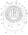
- FIG. 8(A) is a perspective view showing the stator 1.
- FIG. 8A one phase of windings 2U, 2V, and 2W is shown as winding 2.
- the inner layer coils 21U, 21V, and 21W are referred to as “inner layer coils 21" when there is no particular need to distinguish between them.
- the outer layer coils 22U, 22V, and 22W are referred to as “outer layer coils 22" when there is no particular need to distinguish between them.
- FIG. 8(B) is a schematic diagram showing the shapes of the inner layer coil 21 and the outer layer coil 22.
- the inner layer coil 21 has a pair of coil sides 201 extending in the axial direction and a pair of coil ends 202 extending in the circumferential direction.
- the outer layer coil 22 also has the same shape as the inner layer coil 21 .
- the coil side 201 of the inner layer coil 21 and the coil side 201 of the outer layer coil 22 are accommodated in the common slot 13 .
- the coil side 201 of the inner layer coil 21 is located radially inside the coil side 201 of the outer layer coil 22 .
- the coil ends 202 of the inner layer coil 21 and the coil ends 202 of the outer layer coil 22 extend from the common slot 13 to both sides in the circumferential direction.
- the coil ends 202 of the inner layer coil 21 are located radially inside the coil ends 202 of the outer layer coil 22 .
- FIG. 9 is a perspective view showing the electric motor 100.
- FIG. Note that one phase of windings 2U, 2V, and 2W is shown as winding 2 in FIG. Also, the shaft 45 of the rotor 3 is omitted.
- the rotor core 30 protrudes from the stator core 10 in the axial direction.
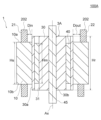
- FIG. Stator core 10 is a cross-sectional view showing the electric motor 100.
- FIG. Stator core 10 has an axial length Hs. Length Hs is the distance from one axial end face 10a of stator core 10 to the other axial end face 10b.
- the rotor core 30 has an axial length Hr.
- the length Hr is the distance from one axial end surface of the rotor core 30 to the other axial end surface.
- the permanent magnet 40 inside the magnet insertion hole 31 of the rotor core 30 has an axial length Hm.
- the length Hm is the distance from one end face to the other end face of the permanent magnet 40 in the axial direction.
- the length Hr of the rotor core 30 is longer than the length Hs of the stator core 10. That is, Hr>Hs holds.
- the rotor core 30 protrudes axially on both sides from the stator core 10 .
- the length Hm of the permanent magnet 40 is less than or equal to the length Hr of the rotor core 30 and longer than the length Hs of the stator core 10. That is, Hr ⁇ Hm>Hs holds.
- the permanent magnets 40 protrude axially on both sides with respect to the stator core 10 .
- the coil ends 202 of the inner layer coil 21 and the coil ends 202 of the outer layer coil 22 face the rotor core 30 in the radial direction.
- the distance Din from the outer circumference 30a of the rotor core 30 to the coil ends 202 of the inner layer coil 21 is It is shorter than the distance Dout from the outer circumference 30 a to the coil end 202 of the outer layer coil 22 .
- the difference in inductance between the inner layer coil 21 and the outer layer coil 22 can be reduced due to the difference in the distances Din and Dout to the rotor core 30 . This point will be described later.
- FIGS. 11A and 11B are schematic diagrams for explaining the winding process of the windings 2U, 2V and 2W.
- the winding process is performed in order from the radially outermost winding 2V.
- an inserter 6 is used as an automatic winding device.
- the inserter 6 has the same number of blades 61 as the slots 13 of the stator core 10 and an annular portion 60 connecting the blades 61 .
- the blades 61 are arranged at regular intervals in the circumferential direction around the axis C1 and extend axially from the annular portion 60 .
- a slit 62 is formed between adjacent blades 61 .
- three outer layer coils 22V are attached to the inserter 6. As shown in FIG. 11(A), first, three outer layer coils 22V are stretched across the three blades 61, respectively.
- the inserter 6 is inserted inside the stator core 10 so that each blade 61 faces the tip of the tooth 12, and then pulled out in the axial direction. As a result, the three outer layer coils 22V stretched over the blades 61 are moved to the teeth 12 .
- the inserter 6 is equipped with three inner layer coils 21V.
- the three inner layer coils 21V are stretched over the blades 61 other than the blade 61 over which the outer layer coil 22V is stretched so that each of the three inner layer coils 21V straddles the three blades 61 . Note that one inner layer coil 21V is hidden in FIG. 11(B).
- the inserter 6 is inserted inside the stator core 10 so that each blade 61 faces the tip of the tooth 12, and then pulled out in the axial direction. As a result, the three outer layer coils 22V stretched over the blades 61 are moved to the teeth 12 . In the slot 13, the inner layer coil 21V is housed radially inside the outer layer coil 22V.
- FIG. 12 is a diagram showing the stator 1C of the electric motor of Comparative Example 1.
- the stator 1C has a stator core 10 and windings 2U, 2V and 2W wound around the stator core 10 by distributed winding.
- the winding 2U has three coils 20U.
- the three coils 20U are arranged at intervals of 120 degrees in the circumferential direction around the axis Ax.
- Each coil 20U is wound across three teeth 12 .
- the winding 2V has three coils 20V.
- the three coils 20V are arranged at intervals of 120 degrees in the circumferential direction around the axis Ax.
- Each coil 20V is wound across three teeth 12 .
- a winding 2W has three coils 20W.
- the three coils 20W are arranged at intervals of 120 degrees in the circumferential direction around the axis Ax.
- Each coil 20W is wound across three teeth 12 .
- the coils 20U, 20V, 20W are arranged so that only two of them overlap in the radial direction. That is, the coils 20U and 20V overlap in the radial direction, the coils 20V and 20W overlap in the radial direction, and the coils 20U and 20W overlap in the radial direction.
- each coil side is inserted into all the slots 13 of the stator core 10 .
- the number of coils 20U, the number of coils 20V, and the number of coils 20W are all half the number of poles P of the rotor 3.
- the coil end of the coil 20U is arranged radially inward
- the coil end of the coil 20V is arranged radially outward
- the coil end of the coil 20W extends from the coil end of the coil 20U in the radial direction to the coil 20V. It is routed radially inward of the coil end.
- the stator 1 has the same slot pitch as in Comparative Example 1, and each of the windings 2U, 2V, and 2W has six coils of the same number as the number of poles P.
- the coil can be made smaller while maintaining the unity factor. Therefore, the winding resistance can be reduced by shortening the average circumference of the winding 2 . By reducing the winding resistance, it is possible to reduce the copper loss and suppress the decrease in the efficiency of the electric motor 100 .
- the wire diameter of the winding 2 can be reduced without changing the winding resistance.
- the amount of conductor used in winding 2 can be reduced, so the manufacturing cost can be reduced without degrading the performance of electric motor 100 .
- each of the windings 2U, 2V, and 2W has six coils, many winding specifications can be achieved by combining these coil connections.
- Embodiment 1 the outer layer coil 22V (FIG. 11A) wound around the stator core 10 is connected in series, and then the inner layer coil 21V (FIG. 11B) wound around the stator core 10 is connected in series. , and then connect them in parallel. Therefore, it is easy to connect the coils 21V and 22V. The same applies to coils 21W, 22W and coils 21U, 22U. Thereby, the productivity of the stator 1 can be improved.
- FIG. 13 is a perspective view showing an electric motor 100D of Comparative Example 2.
- FIG. 13 one phase of windings 2U, 2V, and 2W is shown as winding 2.
- the axial length of rotor core 30 of rotor 3 ⁇ /b>D is equal to the axial length of stator core 10 of stator 1 . That is, rotor core 30 does not protrude from stator core 10 in the axial direction.
- the configuration of stator 1 is the same as that of electric motor 100 of the first embodiment, including windings 2U, 2V and 2W.
- FIG. 14A is a schematic diagram showing currents flowing through the inner layer coil 21 and the outer layer coil 22 of the electric motor 100D of Comparative Example 2.
- FIG. Current I total flowing through winding 2 of a certain phase (for example, winding 2U) differs from current I in according to the impedance ratio of inner layer coil 21 (for example, inner layer coil 21U) and outer layer coil 22 (for example, outer layer coil 22U). The current I out is shunted.
- the inductance Lin of the inner coil 21 is smaller than the inductance Lout of the outer coil 22 .
- impedance is the vector sum of reactance and resistance, the impedance of inner layer coil 21 is smaller than the impedance of outer layer coil 22 .
- FIG. 14B is a graph showing the current I total
- FIG. 14C is a graph showing the current I in
- FIG. 14D is a graph showing the current I out . Due to the difference in impedance between the inner layer coil 21 and the outer layer coil 22, as shown in FIGS . , a phase difference occurs.
- FIG. 15A is a diagram showing the relationship between the current I total and its branch currents I in and I out .
- Current I total is represented by the vector sum of current I in and current I out . Since there is a phase difference between the current I in and the current I out , the directions of the vectors of both are different. Therefore, the sum of the magnitude of the vector of the current I in and the magnitude of the vector of the current I out is greater than the magnitude of the vector of the current I total before shunting.
- the total of the internal copper loss W in generated in the inner layer coil 21 and the internal copper loss W out generated in the outer layer coil 22 was obtained by setting the phase difference to 0. larger than the internal copper loss in the case (that is, the ideal value).
- Such an increase in internal copper loss (symbol D) leads to a decrease in efficiency of electric motor 100 .
- the internal copper loss refers to copper loss caused by the currents I in and I out flowing through the parallel-connected coils 21 and 22 .
- R [ ⁇ ] is the resistance of the winding 2
- ⁇ [rad/s] is the angular velocity
- L [H] is the inductance of the winding 2 .
- the real part R does not depend on the rotation speed of the electric motor 100
- the imaginary part j ⁇ L depends on the rotation speed of the electric motor 100 .
- the compressor performs variable speed operation according to the operating conditions, the component of j ⁇ L changes according to the rotation speed of the electric motor 100 .
- the impedance difference between the inner layer coil 21 and the outer layer coil 22 connected in parallel it is necessary to make both the resistance R and the inductance L nearly uniform.
- the difference in resistance between the inner layer coil 21 and the outer layer coil 22 can be reduced by sharing the conductor material, wire diameter and number of turns of both coils 21 and 22 . Therefore, reducing the difference between the inductance Lin of the inner layer coil 21 and the inductance Lout of the outer layer coil 22 is a problem.
- the axial length Hr of rotor core 30 in the first embodiment is longer than the axial length Hs of stator core 10, and rotor core 30 protrudes from stator core 10 in the axial direction. ing.
- both the coil ends 202 of the inner layer coil 21 and the coil ends 202 of the outer layer coil 22 face the rotor core 30 in the radial direction. Therefore, leakage inductance occurs at the coil end 202 of the inner layer coil 21 and the coil end 202 of the outer layer coil 22 .
- the distance Din from the rotor core 30 to the coil end 202 of the inner layer coil 21 is shorter than the distance Dout from the rotor core 30 to the coil end 202 of the outer layer coil 22 . Therefore, the leakage inductance generated at the coil end 202 of the inner layer coil 21 is larger than the leakage inductance generated at the coil end 202 of the outer layer coil 22 .
- the leakage inductance at the coil end 202 of the inner layer coil 21 is larger than the leakage inductance at the coil end 202 of the outer layer coil 22, the difference between the inductance Lin of the inner layer coil 21 and the inductance Lout of the outer layer coil 22 is reduced. can do.
- FIG. 16A is a schematic diagram showing currents flowing through the inner layer coil 21 and the outer layer coil 22 of the electric motor 100 of the first embodiment.
- the current I total flowing through the winding 2 (eg, winding 2U) of a certain phase is the impedance of the inner layer coil 21 (eg, inner layer coil 21U) and the outer layer coil 22 (eg, outer layer coil 22U).
- the current I in and the current I out are split.
- FIG. 16(B) is a graph showing the current I total
- FIG. 16(C) is a graph showing the current I in
- FIG. 16(D) is a graph showing the current I out .
- FIG. 17A is a diagram showing the relationship between the current I total and the currents I in and I out which are the branch currents thereof. Since the phase difference between the current I in and the current I out is reduced, the direction of the vector of the current I in and the current I out approaches the same direction. That is, the sum of the magnitude of the vector of the current I in and the magnitude of the vector of the current I out approaches the magnitude of the vector of the current I total .
- the total of the internal copper loss W in generated in the inner layer coil 21 and the internal copper loss W out generated in the outer layer coil 22 was obtained by setting the phase difference to 0.
- the value is close to the internal copper loss (that is, the ideal value) in the case. Since an increase in internal copper loss is suppressed in this way, a decrease in efficiency of electric motor 100 can be suppressed.
- L in 1 be the inductance of the inner layer coil 21 of the first embodiment
- L out 1 be the inductance of the outer layer coil 22
- L in 2 be the inductance of the inner layer coil 21 of Comparative Example 2
- L out 2 be the inductance of the outer layer coil 22 .
- L in_arm 1 be the armature inductance of the inner layer coil 21 of the first embodiment
- L in_leak 1 be the leakage inductance
- L in_arm 2 be the armature inductance of the inner layer coil 21 of Comparative Example 2
- L in_leak 2 be the leakage inductance.
- the armature inductance of the outer layer coil 22 of the first embodiment is L out_arm 1 and the leakage inductance is L out_leak 1 .
- the armature inductance of the outer layer coil 22 of Comparative Example 2 is L out_arm 2 and the leakage inductance is L out_leak 2 .
- armature inductances L in_arm 1 and L out_arm 1 of coils 21 and 22 are equivalent to armature inductances L in_arm 2 and L out_arm 2 of coils 21 and 22 in Comparative Example 2, respectively.
- the leakage inductances L in_leak 1 and L out_leak 1 of the coils 21 and 22 are the same as those of the coils 21 and 22 of the comparative example 2. 22 leakage inductance L in_leak 2 and L out_leak 2.
- each coil end 202 of the inner layer coil 21 and the outer layer coil 22 faces the rotor core 30, and the distance Din from the rotor core 30 to the coil end 202 of the inner layer coil 21 is from the rotor core 30 to the outer layer coil. 22 to the coil end 202 , the inductance Lin of the inner layer coil 21 increases more than the inductance Lout of the outer layer coil 22 .
- the difference between the inductance Lin of the inner layer coil 21 and the inductance Lout of the outer layer coil 22 can be made smaller than in the second comparative example.
- the difference in impedance between the inner layer coil 21 and the outer layer coil 22 connected in parallel can be reduced, and the phase difference between the currents I in and I out flowing through them can be reduced.
- the internal copper loss can be reduced, and a decrease in the efficiency of electric motor 100 can be suppressed.
- the rotor core 30 protrudes from the stator core 10 on both sides in the axial direction in FIG. 10, the rotor core 30 may protrude from the stator core 10 on at least one side in the axial direction. However, when the rotor core 30 protrudes from the stator core 10 on both sides in the axial direction, the effect of reducing the impedance difference between the inner layer coil 21 and the outer layer coil 22 is higher.
- FIG. 18 is a perspective view showing an electric motor 100E of Comparative Example 3.
- FIG. 18 one phase of windings 2U, 2V, and 2W is shown as winding 2.
- the rotor 3E of the electric motor 100E has a permanent magnet 41 fixed to the outer circumference of a rotor core 30 having a cylindrical shape.
- the rotor 3E is of the SPM (Surface Permanent Magnet) type.
- the rotor core 30 of the rotor 3E is axially longer than the stator core 10 and protrudes from the stator core 10 in the axial direction.
- Permanent magnet 41 is axially longer than stator core 10 and protrudes axially from stator core 10 . Therefore, each coil end of the inner layer coil 21 and the outer layer coil 22 faces the permanent magnet 41 in the radial direction.
- the relative magnetic permeability of the permanent magnet 41 is close to 1, and the ease with which magnetic flux passes is equivalent to that of air. Therefore, it is difficult for magnetic flux to flow between each coil end of inner layer coil 21 and outer layer coil 22 and rotor core 30, and leakage inductance is less likely to occur at each coil end. Therefore, the effect of reducing the difference in inductance between the inner layer coil 21 and the outer layer coil 22 is poor.
- the electric motor 100 of Embodiment 1 is of the IPM (Interior Permanent Magnet) type in which the permanent magnets 40 are arranged in the magnet insertion holes 31 of the rotor core 30 . Therefore, each coil end 202 of the inner layer coil 21 and the outer layer coil 22 can be opposed to the rotor core 30, and the difference in leakage inductance generated between the two coil ends 202 can be used to separate the inner layer coil 21 and the outer layer coil 22 from each other. It is possible to reduce the difference in inductance, thereby reducing the difference in impedance.
- IPM Interior Permanent Magnet
- the electric motor 100 of the first embodiment includes the stator 1 having the annular stator core 10 and the windings 2U, 2V, 2W wound around the stator core 10 by distributed winding, and arranged inside the stator core 10. and permanent magnets 40 embedded in the rotor core 30 and forming P magnetic poles.
- Each of windings 2U, 2V, and 2W is formed by connecting P/2 inner layer coils 21 connected in series and P/2 outer layer coils 22 connected in series in parallel.
- the inner layer coil 21 is located inside the outer layer coil 22 in the radial direction.
- the inner layer coil 21 and the outer layer coil 22 adjacent in the circumferential direction extend to both sides in the circumferential direction through the common slot 13 of the stator core 10 .
- An axial length Hr of rotor core 30 is longer than an axial length Hs of stator core 10 .
- the coil ends 202 of both the coils 21, 22 can be made small, and thus the windings 2U, 2V, The winding resistance can be reduced by shortening the average circumference of each of 2W.
- the connection work can be easily performed, the productivity of the electric motor 100 can be improved.
- the axial length Hr of the rotor core 30 is longer than the axial length Hs of the stator core 10, the difference in inductance between the inner layer coil 21 and the outer layer coil 22 is reduced, thereby reducing the impedance difference. can be done. As a result, the imbalance between the currents I in and I out can be reduced, and a decrease in the efficiency of the electric motor 100 can be suppressed.
- the rotor core 30 protrudes from the stator core 10 on both sides in the axial direction, the difference in inductance between the inner layer coil 21 and the outer layer coil 22 can be reduced, and the effect of reducing the impedance difference can be enhanced.
- each coil end 202 of the inner layer coil 21 and the outer layer coil 22 faces the rotor core 30 in the radial direction, leakage inductance can be generated at each coil end 202 of the inner layer coil 21 and the outer layer coil 22.
- the difference in leakage inductance of the end 202 can be used to reduce the difference in inductance between the inner layer coil 21 and the outer layer coil 22, thereby reducing the impedance difference.
- the winding 2U is arranged on the innermost side in the radial direction
- the winding 2V is arranged on the outermost side in the radial direction
- the winding 2W is arranged between the windings 2U and 2V in the radial direction.
- the windings 2V, 2W, and 2U can be attached to the stator core 10 in this order, and the productivity of the stator 1 can be improved.
- the order of the U phase, V phase, and W phase is arbitrary.
- the winding coefficient of the electric motor 100 is 1, the magnetic flux of the permanent magnets 40 can be effectively used, and the efficiency of the electric motor 100 can be improved. Further, since the permanent magnet 40 is a rare earth magnet, it is possible to increase the magnetic force, and the output of the electric motor 100 can be increased.
- FIG. 19 is a perspective view showing a modified electric motor 100A.
- one phase of windings 2U, 2V, and 2W is shown as winding 2.
- FIG. 20 is a cross-sectional view showing electric motor 100A.
- 100 A of electric motors of a modification have the stator 1 and the rotor 3A. The configuration of the stator 1 is as described in the first embodiment.
- the axial length Hm of the permanent magnets 40 of the rotor 3A is shorter than the axial length Hs of the stator core 10 . That is, Hm ⁇ Hs holds.
- the axial length Hm of the permanent magnet 40 is shorter than the axial length Hr of the rotor core 30 . Further, as described in the first embodiment, axial length Hs of stator core 10 is shorter than axial length Hr of rotor core 30 . In other words, Hm ⁇ Hs ⁇ Hr holds.
- the coil end 202 of the inner layer coil 21 and the coil end 202 of the outer layer coil 22 of the winding 2 are opposed to the rotor core 30, and the distance Din from the rotor core 30 to the coil end 202 of the inner layer coil 21 is from the rotor core 30. It is shorter than the distance Dout to the coil end 202 of the outer layer coil 22 .
- leakage inductance is generated at coil end 202 of inner layer coil 21 and coil end 202 of outer layer coil 22, and the difference in leakage inductance is used to obtain the inductance of inner layer coil 21 and the outer layer.
- the difference in inductance of the coil 22 can be reduced, thereby reducing the impedance difference.
- axial length Hm of the permanent magnet 40 is equal to or greater than axial length Hs of stator core 10, as in the first embodiment.
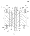
- FIG. 21 is a cross-sectional view showing electric motor 100B of the second embodiment.
- An electric motor 100B of Embodiment 2 has a stator 1 and a rotor 3B.
- the configuration of the stator 1 is as described in the first embodiment.
- the rotor core 30 of the rotor 3B has a first core portion 301 facing the stator core 10 and a second core portion 302 protruding from the stator core 10 in the axial direction.
- the first core portion 301 is also called a stator facing portion
- the second core portion 302 is also called an overhang portion.
- the second core portion 302 is located on both sides of the first core portion 301 in the axial direction, but it is sufficient if it is located on at least one side of the first core portion 301 .
- the magnet insertion hole 31 axially penetrates the first core portion 301 and the second core portion 302 .
- the permanent magnet 40 may be arranged only in the magnet insertion hole 31 of the first core portion 301 , or may be arranged so as to straddle the magnet insertion holes 31 of the first core portion 301 and the magnet insertion holes 31 of the second core portion 302 .
- FIG. 22 is a perspective view showing the rotor 3B.
- first core portion 301 and second core portion 302 have different cross-sectional shapes.
- FIG. 23(A) is a cross-sectional view showing the first core portion 301.
- FIG. FIG. 23B is a cross-sectional view showing the second core portion 302.
- the first core portion 301 has the slit 33 described in the first embodiment radially outside the magnet insertion hole 31 .
- the second core portion 302 does not have the slit 33 radially outside the magnet insertion hole 31 .
- the slits 33 regulate the flow of magnetic flux from the permanent magnets 40 toward the stator 1, thereby reducing torque ripple and reducing the radial excitation force generated when the rotor core 30 is attracted to the stator magnetic field.
- the noise of the electric motor 100B is reduced by reducing the torque ripple and the radial excitation force.
- slits 33 are formed in first core portion 301 facing stator core 10 , and slits 33 are not formed in second core portion 302 not facing stator core 10 .
- the inertia of the rotor 3B can be increased and the rotation can be stabilized.
- the effect of increasing the effective magnetic flux emitted from the permanent magnet 40 and reaching the coils 21 and 22 and improving the efficiency of the electric motor 100 can also be obtained.
- the electric motor 100B of the second embodiment is configured in the same manner as the electric motor 100 of the first embodiment except for the points described above.
- the slit 33 is provided in the first core portion 301 facing the stator core 10, and the slit 33 is not provided in the second core portion 302 protruding from the stator core 10 in the axial direction. As a result, the rotation of the rotor 3B can be stabilized while reducing the noise of the electric motor 100B.
- FIG. 24 is a cross-sectional view showing compressor 500.
- Compressor 500 is a scroll compressor here, but is not limited to this.
- the compressor 500 includes a closed container 507, a compression mechanism 505 arranged in the closed container 507, an electric motor 100 that drives the compression mechanism 505, a shaft 45 that connects the compression mechanism 505 and the electric motor 100, and a shaft 45 and a subframe 508 that supports the lower end of the.
- the compression mechanism 505 includes a fixed scroll 501 having a spiral portion, an orbiting scroll 502 having a spiral portion forming a compression chamber between the spiral portion of the fixed scroll 501 and a compliance frame 503 holding the upper end of the shaft 45 . and a guide frame 504 that is fixed to the sealed container 507 and holds the compliance frame 503 .
- a suction pipe 510 that penetrates a sealed container 507 is press-fitted into the fixed scroll 501 .
- the sealed container 507 is provided with a discharge pipe 511 for discharging the high-pressure refrigerant gas discharged from the fixed scroll 501 to the outside.
- This discharge pipe 511 communicates with an opening (not shown) provided between the compression mechanism 505 of the sealed container 507 and the electric motor 100 .
- the electric motor 100 is fixed to the closed container 507 by fitting the stator 1 into the closed container 507 .
- the configuration of electric motor 100 is as described above.
- a glass terminal 509 for supplying electric power to the electric motor 100 is fixed to the sealed container 507 by welding.
- FIG. 25 is a diagram showing a refrigeration cycle device 400.
- the refrigeration cycle device 400 is, for example, an air conditioner, but is not limited to this.
- a refrigeration cycle device 400 shown in FIG. 25 includes a compressor 401, a condenser 402 that condenses refrigerant, a decompression device 403 that decompresses the refrigerant, and an evaporator 404 that evaporates the refrigerant.
- Compressor 401 , condenser 402 and decompression device 403 are provided in indoor unit 410
- evaporator 404 is provided in outdoor unit 420 .
- the compressor 401, the condenser 402, the decompression device 403 and the evaporator 404 are connected by a refrigerant pipe 407 to form a refrigerant circuit.
- Compressor 401 is composed of compressor 500 shown in FIG.
- the refrigeration cycle device 400 also includes an outdoor fan 405 facing the condenser 402 and an indoor fan 406 facing the evaporator 404 .
- the operation of the refrigeration cycle device 400 is as follows.
- the compressor 401 compresses the sucked refrigerant and sends it out as a high-temperature, high-pressure refrigerant gas.
- the condenser 402 exchanges heat between the refrigerant sent from the compressor 401 and the outdoor air sent by the outdoor fan 405, condenses the refrigerant, and sends it out as a liquid refrigerant.
- the decompression device 403 expands the liquid refrigerant sent from the condenser 402 and sends it out as a low-temperature, low-pressure liquid refrigerant.
- the evaporator 404 exchanges heat between the low-temperature, low-pressure liquid refrigerant sent out from the decompression device 403 and the room air, and evaporates the refrigerant and sends it out.
- the air from which heat has been removed by the evaporator 404 is supplied by the indoor blower 406 into the room, which is the space to be air-conditioned.
- the electric motor 100 described in each embodiment and modifications can be applied to the compressor 401 of the refrigeration cycle device 400 . Since the electric motor 100 has high efficiency, the operating efficiency of the refrigeration cycle device 400 can be improved.
- stator 1 stator, 2 windings, 2U windings (first phase windings), 2V windings (second phase windings), 2W windings (third phase windings), 3, 3A, 3B rotors, 6 inserter 10 stator core 11 core back 12 tooth 13 slot 21, 21U, 21V, 21W inner layer coil 22, 22U, 22V, 22W outer layer coil 30 rotor core 31 magnet insertion hole 32 flux barrier 33 slit , 34 side slit, 40 permanent magnet, 45 shaft, 100, 100A, 100B electric motor, 201 coil side, 202 coil end, 301 first core portion, 302 second core portion, 400 refrigerating cycle device, 401 compressor, 402 condensation vessel, 403 decompression device, 404 evaporator, 410 indoor unit, 420 outdoor unit, 500 compressor, 505 compression mechanism, 507 sealed container.
Landscapes
- Engineering & Computer Science (AREA)
- Power Engineering (AREA)
- Windings For Motors And Generators (AREA)
Priority Applications (2)
| Application Number | Priority Date | Filing Date | Title |
|---|---|---|---|
| PCT/JP2021/032330 WO2023032134A1 (ja) | 2021-09-02 | 2021-09-02 | 電動機、圧縮機および冷凍サイクル装置 |
| JP2023544922A JPWO2023032134A1 (https=) | 2021-09-02 | 2021-09-02 |
Applications Claiming Priority (1)
| Application Number | Priority Date | Filing Date | Title |
|---|---|---|---|
| PCT/JP2021/032330 WO2023032134A1 (ja) | 2021-09-02 | 2021-09-02 | 電動機、圧縮機および冷凍サイクル装置 |
Publications (1)
| Publication Number | Publication Date |
|---|---|
| WO2023032134A1 true WO2023032134A1 (ja) | 2023-03-09 |
Family
ID=85412423
Family Applications (1)
| Application Number | Title | Priority Date | Filing Date |
|---|---|---|---|
| PCT/JP2021/032330 Ceased WO2023032134A1 (ja) | 2021-09-02 | 2021-09-02 | 電動機、圧縮機および冷凍サイクル装置 |
Country Status (2)
| Country | Link |
|---|---|
| JP (1) | JPWO2023032134A1 (https=) |
| WO (1) | WO2023032134A1 (https=) |
Cited By (2)
| Publication number | Priority date | Publication date | Assignee | Title |
|---|---|---|---|---|
| WO2024247100A1 (ja) * | 2023-05-30 | 2024-12-05 | 三菱電機株式会社 | 固定子、電動機、圧縮機、冷凍サイクル装置および固定子の製造方法 |
| WO2025203429A1 (ja) * | 2024-03-28 | 2025-10-02 | 三菱電機株式会社 | ステータ、電動機、圧縮機および冷凍サイクル装置 |
Citations (8)
| Publication number | Priority date | Publication date | Assignee | Title |
|---|---|---|---|---|
| JPH03230744A (ja) * | 1990-02-05 | 1991-10-14 | Mitsubishi Electric Corp | ブラシレスモータ |
| JP2015035837A (ja) * | 2013-08-07 | 2015-02-19 | 株式会社東芝 | 回転電機、及び回転電機の製造方法 |
| WO2015111369A1 (ja) * | 2014-01-22 | 2015-07-30 | パナソニックIpマネジメント株式会社 | 三相モータ |
| JP2015223028A (ja) * | 2014-05-22 | 2015-12-10 | アイシン・エィ・ダブリュ株式会社 | 回転電機用のステータ |
| WO2017175330A1 (ja) * | 2016-04-06 | 2017-10-12 | 三菱電機株式会社 | 電動機、送風機、圧縮機および空気調和装置 |
| WO2019215865A1 (ja) * | 2018-05-10 | 2019-11-14 | 三菱電機株式会社 | ロータ、電動機、圧縮機および空気調和装置 |
| WO2020170422A1 (ja) * | 2019-02-22 | 2020-08-27 | 三菱電機株式会社 | 固定子、電動機及び圧縮機 |
| WO2021033290A1 (ja) * | 2019-08-21 | 2021-02-25 | 三菱電機株式会社 | 回転電機の固定子 |
-
2021
- 2021-09-02 WO PCT/JP2021/032330 patent/WO2023032134A1/ja not_active Ceased
- 2021-09-02 JP JP2023544922A patent/JPWO2023032134A1/ja not_active Withdrawn
Patent Citations (8)
| Publication number | Priority date | Publication date | Assignee | Title |
|---|---|---|---|---|
| JPH03230744A (ja) * | 1990-02-05 | 1991-10-14 | Mitsubishi Electric Corp | ブラシレスモータ |
| JP2015035837A (ja) * | 2013-08-07 | 2015-02-19 | 株式会社東芝 | 回転電機、及び回転電機の製造方法 |
| WO2015111369A1 (ja) * | 2014-01-22 | 2015-07-30 | パナソニックIpマネジメント株式会社 | 三相モータ |
| JP2015223028A (ja) * | 2014-05-22 | 2015-12-10 | アイシン・エィ・ダブリュ株式会社 | 回転電機用のステータ |
| WO2017175330A1 (ja) * | 2016-04-06 | 2017-10-12 | 三菱電機株式会社 | 電動機、送風機、圧縮機および空気調和装置 |
| WO2019215865A1 (ja) * | 2018-05-10 | 2019-11-14 | 三菱電機株式会社 | ロータ、電動機、圧縮機および空気調和装置 |
| WO2020170422A1 (ja) * | 2019-02-22 | 2020-08-27 | 三菱電機株式会社 | 固定子、電動機及び圧縮機 |
| WO2021033290A1 (ja) * | 2019-08-21 | 2021-02-25 | 三菱電機株式会社 | 回転電機の固定子 |
Cited By (2)
| Publication number | Priority date | Publication date | Assignee | Title |
|---|---|---|---|---|
| WO2024247100A1 (ja) * | 2023-05-30 | 2024-12-05 | 三菱電機株式会社 | 固定子、電動機、圧縮機、冷凍サイクル装置および固定子の製造方法 |
| WO2025203429A1 (ja) * | 2024-03-28 | 2025-10-02 | 三菱電機株式会社 | ステータ、電動機、圧縮機および冷凍サイクル装置 |
Also Published As
| Publication number | Publication date |
|---|---|
| JPWO2023032134A1 (https=) | 2023-03-09 |
Similar Documents
| Publication | Publication Date | Title |
|---|---|---|
| US8405272B2 (en) | Self-starting permanent magnet synchronous motor and compressor and refrigeration cycle using the same | |
| US20120131945A1 (en) | Self-Starting Type Axial Gap Synchronous Motor, Compressor and Refrigeration Cycle Apparatus Using the Same | |
| EP3633827B1 (en) | Electric motor, compressor, and air conditioning device | |
| CN108886276B (zh) | 电动机、送风机、压缩机及空气调节装置 | |
| US11863020B2 (en) | Motor, compressor, and air conditioner | |
| CN110622394B (zh) | 定子、电动机、压缩机及空调装置 | |
| JP7150181B2 (ja) | モータ、圧縮機、及び空気調和機 | |
| CN113574768A (zh) | 转子、马达、压缩机以及空调机 | |
| WO2019215865A1 (ja) | ロータ、電動機、圧縮機および空気調和装置 | |
| CN110112847A (zh) | 同步磁阻电机转子结构及具有其的电机 | |
| WO2023032134A1 (ja) | 電動機、圧縮機および冷凍サイクル装置 | |
| US20230291263A1 (en) | Stator, electric motor, compressor, air conditioner, and method for fabricating stator | |
| US20230208232A1 (en) | Stator, electric motor, compressor, and air conditioner | |
| US11888370B2 (en) | Stator, motor, compressor, air conditioner, and manufacturing method of stator | |
| AU2023208167A1 (en) | Rotor, electric motor, compressor, and air conditioner | |
| JPWO2020026431A1 (ja) | ステータ、モータ、圧縮機、及び冷凍空調装置 | |
| JP7353508B2 (ja) | 固定子、電動機、圧縮機および空気調和装置 | |
| JP7486911B2 (ja) | 電動機、圧縮機、冷凍サイクル装置、着磁方法および着磁装置 | |
| JP7419501B2 (ja) | 着磁方法、電動機の製造方法、電動機、圧縮機、及び空気調和機 | |
| JP7286019B2 (ja) | 固定子、電動機、圧縮機、冷凍サイクル装置及び空気調和装置 | |
| WO2024247100A1 (ja) | 固定子、電動機、圧縮機、冷凍サイクル装置および固定子の製造方法 | |
| WO2023148844A1 (ja) | 電動機、圧縮機および冷凍サイクル装置 | |
| WO2023152891A1 (ja) | リラクタンスモータ駆動装置、リラクタンスモータユニット、圧縮機及び空気調和装置 | |
| WO2022180717A1 (ja) | 電動機、圧縮機および冷凍サイクル装置 | |
| WO2023037438A1 (ja) | ロータ、モータ、圧縮機および冷凍サイクル装置 |
Legal Events
| Date | Code | Title | Description |
|---|---|---|---|
| 121 | Ep: the epo has been informed by wipo that ep was designated in this application |
Ref document number: 21956023 Country of ref document: EP Kind code of ref document: A1 |
|
| WWE | Wipo information: entry into national phase |
Ref document number: 2023544922 Country of ref document: JP |
|
| NENP | Non-entry into the national phase |
Ref country code: DE |
|
| 122 | Ep: pct application non-entry in european phase |
Ref document number: 21956023 Country of ref document: EP Kind code of ref document: A1 |