WO2023026992A1 - コネクタ - Google Patents
コネクタ Download PDFInfo
- Publication number
- WO2023026992A1 WO2023026992A1 PCT/JP2022/031428 JP2022031428W WO2023026992A1 WO 2023026992 A1 WO2023026992 A1 WO 2023026992A1 JP 2022031428 W JP2022031428 W JP 2022031428W WO 2023026992 A1 WO2023026992 A1 WO 2023026992A1
- Authority
- WO
- WIPO (PCT)
- Prior art keywords
- housing
- terminal
- box
- connector
- connection
- Prior art date
- Legal status (The legal status is an assumption and is not a legal conclusion. Google has not performed a legal analysis and makes no representation as to the accuracy of the status listed.)
- Ceased
Links
Images


Classifications
-
- H—ELECTRICITY
- H01—ELECTRIC ELEMENTS
- H01R—ELECTRICALLY-CONDUCTIVE CONNECTIONS; STRUCTURAL ASSOCIATIONS OF A PLURALITY OF MUTUALLY-INSULATED ELECTRICAL CONNECTING ELEMENTS; COUPLING DEVICES; CURRENT COLLECTORS
- H01R13/00—Details of coupling devices of the kinds covered by groups H01R12/70 or H01R24/00 - H01R33/00
- H01R13/02—Contact members
- H01R13/10—Sockets for co-operation with pins or blades
- H01R13/11—Resilient sockets
-
- H—ELECTRICITY
- H01—ELECTRIC ELEMENTS
- H01R—ELECTRICALLY-CONDUCTIVE CONNECTIONS; STRUCTURAL ASSOCIATIONS OF A PLURALITY OF MUTUALLY-INSULATED ELECTRICAL CONNECTING ELEMENTS; COUPLING DEVICES; CURRENT COLLECTORS
- H01R31/00—Coupling parts supported only by co-operation with counterpart
- H01R31/08—Short-circuiting members for bridging contacts in a counterpart
-
- H—ELECTRICITY
- H01—ELECTRIC ELEMENTS
- H01R—ELECTRICALLY-CONDUCTIVE CONNECTIONS; STRUCTURAL ASSOCIATIONS OF A PLURALITY OF MUTUALLY-INSULATED ELECTRICAL CONNECTING ELEMENTS; COUPLING DEVICES; CURRENT COLLECTORS
- H01R4/00—Electrically-conductive connections between two or more conductive members in direct contact, i.e. touching one another; Means for effecting or maintaining such contact; Electrically-conductive connections having two or more spaced connecting locations for conductors and using contact members penetrating insulation
- H01R4/58—Electrically-conductive connections between two or more conductive members in direct contact, i.e. touching one another; Means for effecting or maintaining such contact; Electrically-conductive connections having two or more spaced connecting locations for conductors and using contact members penetrating insulation characterised by the form or material of the contacting members
Definitions
- This disclosure relates to connectors.
- Patent Document 1 discloses a housing that holds a busbar and another connector that accommodates a plurality of connection terminals.
- the housing has a connector fitting chamber.
- the bus bar has a branch terminal portion protruding into the connector fitting chamber.
- Another connector is fitted into the connector fitting chamber of the housing.
- the connection terminal has a cylindrical connection portion (hereinafter referred to as "box portion") connected to the branch terminal portion.
- a contact piece that contacts the branch terminal portion is provided inside the box portion.
- the inside of the box part is shaped so that the branch terminal part can be positioned and inserted, and is designed so that the contact piece is positioned facing the inserted branch terminal part. For this reason, there is a situation that the shape of the inside of the box portion is restricted, and the degree of freedom in designing the connection terminal is also restricted.
- an object of the present disclosure is to provide a connector capable of improving the degree of freedom in designing connection terminals.
- a connector includes a housing, a connection terminal arranged inside the housing, and a mounting terminal mounted on the housing, the connection terminal having a cylindrical box portion and the mounting terminal having a cylindrical box portion.
- the terminal has a contact portion that contacts the outer surface of the box portion and is electrically connected to the connection terminal.
- connection terminals it is possible to provide a connector capable of improving the degree of freedom in designing connection terminals.
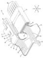
- FIG. 1 is an exploded perspective view of a connector according to an embodiment of the present disclosure
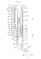
- FIG. FIG. 2 is a perspective view of the connector in a mated state.
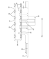
- FIG. 3 is a side sectional view showing a state in which the contact portion of the mounting terminal is electrically connected to the connecting terminal.
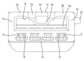
- FIG. 4 is a rear view of the housing.
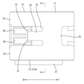
- FIG. 5 is a plan view of the housing. 6 is a cross-sectional view taken along the line AA of FIG. 5.
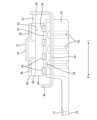
- FIG. FIG. 7 is a front view of the branch portion side of the mounting terminal.
- FIG. 8 is a front view of the mounting terminal on the main body side.
- the connector of the present disclosure is (1) A housing, a connection terminal arranged inside the housing, and a mounting terminal mounted on the housing, the connection terminal having a cylindrical box portion, the mounting terminal comprising: It has a contact portion that contacts the outer surface of the box portion and is electrically connected to the connection terminal.
- the contact portion of the mounting terminal contacts the outer surface of the box portion of the connection terminal, the shape of the inside of the box portion can be freely designed without restriction.
- the degree of freedom in designing the connection terminals can be improved.
- general-purpose female terminals can be used as the connection terminals.
- the connection terminal can be a simple one that does not have a contact piece inside the box.
- the contact portion preferably has a pair of clamping pieces that clamp the box portion. According to the above configuration, the state in which the contact portion is in contact with the outer surface of the box portion can be maintained satisfactorily, and the reliability of the connection can be ensured.
- the contact portion has a connection portion that connects the pair of holding pieces, and when the direction in which the pair of holding pieces sandwiches the box portion is the height direction, the connection portion It is preferable that it is formed so as to extend in the vertical direction. According to the above configuration, it is possible to easily form the folded connecting portion by utilizing the height of the box portion.
- a lance for locking the connection terminal is provided inside the housing, and a die-cut hole is provided in the end face of the housing to open the lance so that the lance can be visually recognized.
- One of them is preferably arranged inside the punched hole.
- the punching hole formed by pulling out the mold for molding the lance can be used as a space for arranging the clamping piece inside the housing, thereby simplifying the structure of the housing. be able to.
- it since it is not necessary to provide a dedicated insertion hole for inserting the clamping piece in the end face of the housing, it becomes easier to ensure the rigidity of the end face of the housing, and it is possible to cope with the downsizing of the housing.
- the mounting terminal has a flat-plate-shaped holding portion continuous from the contact portion, and the housing has a slit for positioning the holding portion. According to the above configuration, there is no need to provide a tubular guide such as a hood for guiding fitting with the housing on the mounting terminal side, or even if a tubular guide is provided, the structure can be simplified.
- This embodiment exemplifies a connector 10 provided at a branch portion of a conductive path of a vehicle.
- the connector 10 includes a housing 11 , a plurality of connection terminals 12 accommodated in the housing 11 , and attachment terminals 13 fitted and attached to the housing 11 .
- the mounting terminal 13 is a ground terminal, electrically connected to each connection terminal 12 inside the housing 11, and electrically connected to the ground side of the vehicle body or the like outside the housing 11. ing.
- the front-rear direction the side where the mounting terminal 13 is mounted on the housing 11 is defined as the front side.
- the vertical direction is synonymous with the height direction, and the vertical direction in each figure except FIG. 5 is used as a reference.
- the left-right direction is synonymous with the width direction, and the left-right direction in FIGS. 1 and 2 is used as a reference.
- Symbols F, B, U, D, L, and R in the drawings indicate the front side, rear side, upper side, lower side, left side, and right side, respectively. These directions are merely defined for convenience of explanation, and do not limit the mode of use.
- the housing 11 is made of synthetic resin, and has a rectangular flat shape in plan view, as shown in FIGS.
- the housing 11 has a plurality of cavities 14 as shown in FIG.
- the cavities 14 are arranged in a line on the left and right inside the housing 11 .
- the housing 11 has a plurality of lances 15. As shown in FIG. 3, each lance 15 protrudes rearward from the lower surface of each cavity 14 and is elastically deformable up and down. As shown in FIG. 4, an end wall 16 is formed on the rear surface of the housing 11 .
- the end wall 16 is formed with a plurality of die-cutting holes 17 formed by drawing out a mold for forming each lance 15 .
- Each die-cutting hole 17 is arranged behind each lance 15 so as to face each lance 15 .
- Each lance 15 is visible from behind through each die-cut hole 17, as shown in FIG.
- the rear surface of each cavity 14 is closed by an end wall 16 except for each die-cut hole 17 .
- a slit 18 is formed along the width direction in the upper part of the housing 11 .
- the slit 18 is open to the rear of the housing 11 .
- the lower surface of slit 18 is closed by closing wall 19 .
- a closing wall 19 separates the slit 18 from each cavity 14 .
- Both side surfaces of the slit 18 are closed by left and right side walls 21 .
- the upper surface of the slit 18 is closed by left and right guide walls 22, a construction wall 23, and a lock portion 24.
- the guide wall 22 protrudes inward in the width direction from the upper portion of the side wall 21 .
- the construction wall 23 spans between the front portions of the left and right guide walls 22 .
- the lock portion 24 protrudes rearward from the left-right central portion of the construction wall 23 .
- the upper surfaces of the guide wall 22, the installation wall 23, and the lock portion 24 are arranged flat without steps.
- a claw-like locking projection 25 is formed at the tip of the locking portion 24 so as to protrude downward.
- Each opening 26 has a rectangular shape in plan view for each cavity 14 in the upper portion of the housing 11 and communicates with each cavity 14 .
- the housing 11 has ribs 27 extending in the front-rear direction on one side wall 21A of the side walls 21 .
- the connection terminal 12 is made of a conductive metal plate.
- the connection terminal 12 has, as shown in FIGS. 1 and 3 , a box portion 28 and an open-barrel-shaped barrel portion 29 connected to the front of the box portion 28 .
- the barrel portion 29 is crimped and connected to the terminal portion of the electric wire W1.
- the box portion 28 has a square tubular shape with a closed rear surface, and has a hollow structure in which no contact piece or the like is formed inside. As shown in FIG. 3, a lance hole 66 is formed through the lower wall of the box portion 28 .
- the mounting terminal 13 is also made of a conductive metal plate.
- the mounting terminal 13 has, as shown in FIG. 1 , a body portion 31 , a branch portion 32 and a base portion 33 .
- the base portion 33 has a flat plate shape extending in the front-rear direction and the left-right direction, and has an attachment piece 34 bent rearward at the rear edge.
- the mounting piece 34 is fixed to the ground side of the vehicle body or the like.
- the branch portion 32 and the main body portion 31 are arranged side by side with the base portion 33 interposed therebetween.
- the branch portion 32 has a base portion 35, a lower plate portion 36, an upper plate portion 37, a horizontal plate portion 38, and a plurality of connecting pieces 39, as shown in FIG.
- the base portion 35 has a shape of an upright plate rising from the right side of the front edge of the base portion 33 in FIG.
- the lower plate portion 36 has a flat plate shape, protrudes forward from the upper portion of the base portion 35, and has portions that protrude to both the left and right sides.
- the upper plate portion 37 also has a flat plate shape and faces the lower plate portion 36 above the lower plate portion 36 in parallel.
- the horizontal plate portion 38 is connected to the right edge of each of the upper plate portion 37 and the lower plate portion 36 .
- connection pieces 39 are tab-shaped and protrude forward from the front edges of the upper plate portion 37 and the lower plate portion 36, respectively.
- the connection pieces 39 are arranged side by side on the front edge of each of the upper plate portion 37 and the lower plate portion 36 .
- a female housing 41 is fitted to the branch portion 32 from the front as shown in FIGS.
- the female housing 41 is made of synthetic resin, has a rectangular flat shape in plan view, and is slightly larger than the housing 11 .
- a pair of upper and lower mounting grooves 42 are opened in the rear surface of the female housing 41 .
- the upper plate portion 37 and the lower plate portion 36 are respectively inserted into the upper and lower mounting grooves 42 from behind.
- a plurality of female terminal fittings (not shown) are inserted into the female housing 41 from the front.
- Each female terminal fitting faces a pair of upper and lower mounting grooves 42 , and each connecting piece 39 is inserted thereinto to be electrically connected to the branch portion 32 .
- each female terminal fitting is electrically connected to the end portion of the electric wire W2.
- Each electric wire W2 is pulled forward from the front surface of the female housing 41, as shown in FIG.
- the body portion 31 includes a root portion 43, a bottom plate portion 44, a one side plate portion 45, the other side plate portion 46, a connecting portion 47, a contact portion 48, and a holding portion 49. and have
- the root portion 43 has a shape of an upright plate rising from the left side of the front edge of the base portion 33 in FIG.
- the bottom plate portion 44 has a flat plate shape that is rectangular in plan view, protrudes forward from the upper portion of the base portion 43, and has portions that protrude to both the left and right sides.
- the bottom plate portion 44 is arranged one step higher than the base portion 33 via the root portion 43 .
- the one side plate portion 45 has a shape rising from the left side of the bottom plate portion 44 in FIG. As shown in FIG. 1, a vertical step 51 is formed on the upper edge of the one side plate portion 45 . Of the upper edges of the one side plate portion 45 , the rear upper edge, which is the rear side of the step 51 , is arranged one step lower than the front upper edge, which is the front side of the step 51 .
- the other side plate portion 46 has a shape rising from the right side of the bottom plate portion 44 in FIG.
- the other side plate portion 46 is formed with a height lower than that of the one side plate portion 45 .
- the connecting portion 47 has a shape extending from the rear upper edge of the one side plate portion 45 to the other side plate portion 46 side (right side in FIG. 1) while being bent.
- the connecting portion 47 is a portion interposed between the one side plate portion 45 and the contact portion 48 to connect them.
- the contact portion 48 has upper and lower holding pieces 52 and 53 and a connecting portion 54 that connects the holding pieces 52 and 53 together.
- the upper clamping piece 52 extends continuously from the connecting portion 47 to the side of the other side plate portion 46, and has the other side edge at a position on one side of the other side plate portion 46 in the left-right direction. have.
- the upper clamping piece 52 has a flat plate shape extending in the left-right direction and the front-rear direction, and has a portion projecting forward from the connecting portion 47 .
- the upper clamping piece 52 has such rigidity that it cannot be elastically deformed.
- the lower clamping piece 53 is arranged below the upper clamping piece 52 so as to face it.
- the lower clamping piece 53 has a band plate portion 55 along the left-right direction and a plurality of elastic contact portions 56 projecting forward from the front edge of the band plate portion 55 .
- the elastic contact portions 56 are arranged side by side on the front edge of the band plate portion 55 .
- Each elastic contact portion 56 is elastically deformable up and down with the front edge of the band plate portion 55 as a fulcrum. When each elastic contact portion 56 is in a natural state without elastic deformation, each elastic contact portion 56 is inclined upward from the front edge of the band plate portion 55 toward the front and bent downward from the contact portion 57 positioned at the upper end. ing.
- the connecting portion 54 extends in the vertical direction as a whole between the rear portions of the clamping pieces 52 and 53 and has a shape folded back into a U shape.
- the width dimension of the connecting portion 54 is the same as the width dimension of each of the clamping pieces 52 and 53, as shown in FIG.
- the extension length (vertical dimension) of the connecting portion 54 is the same as the vertical separation distance between the clamping pieces 52 and 53, and corresponds to the vertical dimension of the box portion 28 of the terminal fitting.
- the holding portion 49 includes a relay portion 58 that slopes forward from the upper clamping piece 52, and a front end of the relay portion 58 that extends forward in the front-rear direction. and a holding body portion 59 .
- the holding portion 49 has a bulging portion 61 extending in the front-rear direction from the relay portion 58 to the holding body portion 59 at the center portion in the left-right direction.
- the bulging portion 61 has a bent trapezoidal shape when viewed from the front, and has a flat upper wall.
- an upper wall of the bulging portion 61 is formed with a lock hole 62 that is rectangular in plan view.
- the holding body portion 59 is fitted into the slit 18 of the housing 11 as shown in FIG. With the holding main body 59 fitted in the slit 18 , the locking projection 25 of the locking portion 24 is fitted into the locking hole 62 of the bulging portion 61 so as to be locked.
- the portion extending from one side of the base portion 33 (left side in FIG. 1) to the rear portion of the bottom plate portion 44 and the portion extending from the other side of the base portion 33 (right side in FIG. 1) to the rear portion of the lower plate portion 36 are: A plurality of protrusions 63 are provided side by side.
- a female housing 41 is fitted to the branched portion 32 of the mounting terminal 13 as shown in FIG.
- Each connection piece 39 of the branch portion 32 is electrically connected to each female terminal fitting.
- a connection terminal 12 is inserted into each cavity 14 of the housing 11 .
- the connection terminal 12 is temporarily retained in the cavity 14 by fitting the lance 15 into the lance hole 66 and engaging the lance 15 .
- the connection terminal 12 is retained by a retainer 64 attached to the housing 11 and is secondarily prevented from coming out of the cavity 14 .
- the box portion 28 of the connection terminal 12 has its rear surface, which is a closed surface, abutted against the end wall 16 of the housing 11 and its upper surface exposed upward from the opening 26 .
- the housing 11 is fitted to the body portion 31 of the mounting terminal 13 as shown in FIG.
- Each elastic contact portion 56 of the main body portion 31 is covered with the upper clamping piece 52 and the holding portion 49 before being fitted with the housing 11, and is covered with the bottom plate portion 44 below. Both the left and right sides are covered with the other side plate portion 46 . That is, each elastic contact portion 56 is protected on four sides before being fitted with the housing 11 .
- the holding main body portion 59 is fitted inside the housing 11 surrounded by the closing wall 19, the left and right side walls 21 and the guide walls 22, and the main body portion 31 is fitted. Movement is guided.
- the locking portion 24 of the housing 11 is elastically deformed by sliding on the upper surface of the upper wall of the bulging portion 61 during the fitting process.
- the locking portion 24 is elastically restored, and the locking projection 25 is fitted into the locking hole 62 as shown in FIG. As a result, the mounting terminal 13 is held in a fitted state with the housing 11 .
- the relay portion 58 faces the rear edge of the closing wall 19 , and the holding body portion 59 is positioned in the slit 18 between the installation wall 23 and the closing wall 19 . positioned in between.
- the housing 11 is supported by the bottom plate portion 44 and sandwiched between the one side plate portion 45 and the other side plate portion 46 in the width direction.
- the upper clamping pieces 52 cover the rear openings of the cavities 14 and allow the connection terminals 12 to pass through the openings 26. It contacts the upper surface of the box portion 28 .
- Each elastic contact portion 56 of the lower clamping piece 53 faces the inside of the cavity 14 through each die-cut hole 17 and contacts each contact portion 57 with the lower surface of the box portion 28 of each connection terminal 12 .
- Each elastic contact portion 56 comes into contact with the box portion 28 and is elastically deformed. In this manner, the contact portion 48 of the mounting terminal 13 contacts the outer surface of the box portion 28 with the box portion 28 sandwiched between the clamping pieces 52 and 53, and is electrically connected to the connection terminal 12. .
- the contact portion 48 of the mounting terminal 13 contacts the outer surface of the box portion 28 of the connection terminal 12, the inner shape of the box portion 28 can be freely changed without restriction. can be designed to As a result, the degree of freedom in designing the connection terminals 12 can be improved.
- the connection terminal 12 has a simple shape without a contact piece inside the box portion 28 . Therefore, costs can be reduced.
- connection state between the mounting terminal 13 and the connection terminal 12 can be maintained even under vibration, for example. , can improve the reliability of the connection.
- the connecting portion 54 extends in the same height direction as the sandwiching direction of the clamping pieces 52 and 53 with respect to the box portion 28, the height of the box portion 28 is used to easily fold the connecting portion 54 without difficulty. can be formed into
- the die-cut hole 17 formed in the end wall 16 of the housing 11 along with the molding of the lance 15 serves as an insertion hole for the lower clamping piece 53 to pass through, the end wall 16 does not have to be provided with a dedicated insertion hole. done. As a result, the rigidity of the end wall 16 of the housing 11 can be easily ensured, and the size of the housing 11 can be reduced.
- the mounting terminal 13 can be of a simple structure.
- connection terminal had a box portion with a hollow structure.
- connection terminal may be a general-purpose female terminal fitting having a contact piece or the like inside the box portion.
- the mounting terminal is not provided with a cylindrical guide for guiding the fitting operation with the housing.
- the mounting terminal may be provided with a cylindrical guide.
- the holding portion can be positioned in the slit and exhibit a guiding function, the tubular guide can be made simple in structure.
- the contact portion of the mounting terminal has a structure in which the box portion is sandwiched between the upper clamping piece and the elastic contact portion.
- the contact portion of the mounting terminal may have a structure in which only the elastic contact portion contacts the box portion without the upper clamping piece.
- the elastic contact portion of each mounting terminal is provided for each connection terminal so as to individually contact the box portion of each connection terminal.
- the elastic contact portion of each mounting terminal may be provided corresponding to a plurality of connection terminals so as to collectively contact the box portions of the plurality of connection terminals.
Landscapes
- Connector Housings Or Holding Contact Members (AREA)
Priority Applications (1)
| Application Number | Priority Date | Filing Date | Title |
|---|---|---|---|
| CN202280056663.8A CN117882252A (zh) | 2021-08-27 | 2022-08-19 | 连接器 |
Applications Claiming Priority (2)
| Application Number | Priority Date | Filing Date | Title |
|---|---|---|---|
| JP2021138568A JP7539023B2 (ja) | 2021-08-27 | 2021-08-27 | コネクタ |
| JP2021-138568 | 2021-08-27 |
Publications (1)
| Publication Number | Publication Date |
|---|---|
| WO2023026992A1 true WO2023026992A1 (ja) | 2023-03-02 |
Family
ID=85322104
Family Applications (1)
| Application Number | Title | Priority Date | Filing Date |
|---|---|---|---|
| PCT/JP2022/031428 Ceased WO2023026992A1 (ja) | 2021-08-27 | 2022-08-19 | コネクタ |
Country Status (3)
| Country | Link |
|---|---|
| JP (2) | JP7539023B2 (enExample) |
| CN (1) | CN117882252A (enExample) |
| WO (1) | WO2023026992A1 (enExample) |
Citations (4)
| Publication number | Priority date | Publication date | Assignee | Title |
|---|---|---|---|---|
| JP2006108050A (ja) * | 2004-10-08 | 2006-04-20 | Fujikura Ltd | ジョイントコネクタ |
| JP2008204720A (ja) * | 2007-02-19 | 2008-09-04 | Auto Network Gijutsu Kenkyusho:Kk | 短絡部材、短絡部材付電線、ジョイントコネクタおよび短絡方法 |
| JP2011103192A (ja) * | 2009-11-10 | 2011-05-26 | Sumitomo Wiring Syst Ltd | ジョイントコネクタ及びワイヤハーネス |
| JP2013254596A (ja) * | 2012-06-05 | 2013-12-19 | Sumitomo Wiring Syst Ltd | ジョイントコネクタ |
Family Cites Families (3)
| Publication number | Priority date | Publication date | Assignee | Title |
|---|---|---|---|---|
| JPH08190971A (ja) * | 1995-01-10 | 1996-07-23 | Sumitomo Wiring Syst Ltd | ジョイントコネクタ |
| JP2008198392A (ja) * | 2007-02-08 | 2008-08-28 | Auto Network Gijutsu Kenkyusho:Kk | ジョイントコネクタ |
| JP5668655B2 (ja) * | 2011-09-20 | 2015-02-12 | 株式会社オートネットワーク技術研究所 | 導電板およびジョイントコネクタ |
-
2021
- 2021-08-27 JP JP2021138568A patent/JP7539023B2/ja active Active
-
2022
- 2022-08-19 CN CN202280056663.8A patent/CN117882252A/zh active Pending
- 2022-08-19 WO PCT/JP2022/031428 patent/WO2023026992A1/ja not_active Ceased
-
2024
- 2024-06-28 JP JP2024104624A patent/JP7720026B2/ja active Active
Patent Citations (4)
| Publication number | Priority date | Publication date | Assignee | Title |
|---|---|---|---|---|
| JP2006108050A (ja) * | 2004-10-08 | 2006-04-20 | Fujikura Ltd | ジョイントコネクタ |
| JP2008204720A (ja) * | 2007-02-19 | 2008-09-04 | Auto Network Gijutsu Kenkyusho:Kk | 短絡部材、短絡部材付電線、ジョイントコネクタおよび短絡方法 |
| JP2011103192A (ja) * | 2009-11-10 | 2011-05-26 | Sumitomo Wiring Syst Ltd | ジョイントコネクタ及びワイヤハーネス |
| JP2013254596A (ja) * | 2012-06-05 | 2013-12-19 | Sumitomo Wiring Syst Ltd | ジョイントコネクタ |
Also Published As
| Publication number | Publication date |
|---|---|
| CN117882252A (zh) | 2024-04-12 |
| JP7539023B2 (ja) | 2024-08-23 |
| JP2024114903A (ja) | 2024-08-23 |
| JP7720026B2 (ja) | 2025-08-07 |
| JP2023032437A (ja) | 2023-03-09 |
Similar Documents
| Publication | Publication Date | Title |
|---|---|---|
| JPS5911414Y2 (ja) | 電気接続子 | |
| US8876543B2 (en) | Connector | |
| JP4042674B2 (ja) | コネクタ | |
| US20070099520A1 (en) | Connecting terminal | |
| US6325680B1 (en) | Female contact for an electrical connector | |
| CN110534951B (zh) | 连接器 | |
| JP2023014714A (ja) | 電気接続箱 | |
| JP3567818B2 (ja) | コネクタ | |
| CN111033912B (zh) | 连接器外壳以及连接器 | |
| JP2006100232A (ja) | 端子金具及びこれを用いたコネクタ | |
| JP5155116B2 (ja) | 二重係止コネクタ | |
| WO2023026992A1 (ja) | コネクタ | |
| CN114830454B (zh) | 端子零件及连接器 | |
| JP5565184B2 (ja) | コネクタ | |
| US20250385467A1 (en) | Connector | |
| JP2010009801A (ja) | コネクタ | |
| JP2023090004A (ja) | コネクタ | |
| JP7567719B2 (ja) | コネクタ | |
| JP7498435B2 (ja) | ジョイント端子 | |
| JP2019201001A (ja) | ヒューズの断続構造 | |
| JP2002134213A (ja) | ジョイントコネクタ | |
| JP2023168717A (ja) | コネクタ | |
| JP2025050231A (ja) | コネクタ | |
| JP5034791B2 (ja) | コネクタ | |
| JP2023136521A (ja) | 雌端子 |
Legal Events
| Date | Code | Title | Description |
|---|---|---|---|
| 121 | Ep: the epo has been informed by wipo that ep was designated in this application |
Ref document number: 22861280 Country of ref document: EP Kind code of ref document: A1 |
|
| WWE | Wipo information: entry into national phase |
Ref document number: 202280056663.8 Country of ref document: CN |
|
| NENP | Non-entry into the national phase |
Ref country code: DE |
|
| 122 | Ep: pct application non-entry in european phase |
Ref document number: 22861280 Country of ref document: EP Kind code of ref document: A1 |