WO2023026712A1 - Grating coupler - Google Patents
Grating coupler Download PDFInfo
- Publication number
- WO2023026712A1 WO2023026712A1 PCT/JP2022/027386 JP2022027386W WO2023026712A1 WO 2023026712 A1 WO2023026712 A1 WO 2023026712A1 JP 2022027386 W JP2022027386 W JP 2022027386W WO 2023026712 A1 WO2023026712 A1 WO 2023026712A1
- Authority
- WO
- WIPO (PCT)
- Prior art keywords
- refractive index
- light
- diffraction grating
- modified refractive
- base material
- Prior art date
Links
- 239000000463 material Substances 0.000 claims abstract description 101
- 230000008878 coupling Effects 0.000 claims abstract description 70
- 238000010168 coupling process Methods 0.000 claims abstract description 70
- 238000005859 coupling reaction Methods 0.000 claims abstract description 70
- 230000003287 optical effect Effects 0.000 claims description 50
- 230000003321 amplification Effects 0.000 claims description 13
- 238000003199 nucleic acid amplification method Methods 0.000 claims description 13
- 230000005484 gravity Effects 0.000 description 12
- 238000010586 diagram Methods 0.000 description 7
- 239000013307 optical fiber Substances 0.000 description 6
- 230000000737 periodic effect Effects 0.000 description 6
- 238000013461 design Methods 0.000 description 5
- 238000000034 method Methods 0.000 description 5
- 230000000052 comparative effect Effects 0.000 description 4
- 238000012986 modification Methods 0.000 description 4
- 230000004048 modification Effects 0.000 description 4
- 229910004298 SiO 2 Inorganic materials 0.000 description 3
- 230000005684 electric field Effects 0.000 description 3
- VYPSYNLAJGMNEJ-UHFFFAOYSA-N Silicium dioxide Chemical compound O=[Si]=O VYPSYNLAJGMNEJ-UHFFFAOYSA-N 0.000 description 2
- 230000001902 propagating effect Effects 0.000 description 2
- 238000013519 translation Methods 0.000 description 2
- 239000013598 vector Substances 0.000 description 2
- XUIMIQQOPSSXEZ-UHFFFAOYSA-N Silicon Chemical compound [Si] XUIMIQQOPSSXEZ-UHFFFAOYSA-N 0.000 description 1
- 238000013459 approach Methods 0.000 description 1
- 230000005540 biological transmission Effects 0.000 description 1
- 230000008859 change Effects 0.000 description 1
- 230000007257 malfunction Effects 0.000 description 1
- 230000007246 mechanism Effects 0.000 description 1
- 230000000149 penetrating effect Effects 0.000 description 1
- 239000004038 photonic crystal Substances 0.000 description 1
- 230000010287 polarization Effects 0.000 description 1
- 230000005855 radiation Effects 0.000 description 1
- 238000012552 review Methods 0.000 description 1
- 229910052710 silicon Inorganic materials 0.000 description 1
- 239000010703 silicon Substances 0.000 description 1
- 235000012239 silicon dioxide Nutrition 0.000 description 1
- 239000000377 silicon dioxide Substances 0.000 description 1
- 239000000758 substrate Substances 0.000 description 1
Images


Classifications
-
- G—PHYSICS
- G02—OPTICS
- G02B—OPTICAL ELEMENTS, SYSTEMS OR APPARATUS
- G02B5/00—Optical elements other than lenses
- G02B5/18—Diffraction gratings
-
- G—PHYSICS
- G02—OPTICS
- G02B—OPTICAL ELEMENTS, SYSTEMS OR APPARATUS
- G02B6/00—Light guides; Structural details of arrangements comprising light guides and other optical elements, e.g. couplings
- G02B6/10—Light guides; Structural details of arrangements comprising light guides and other optical elements, e.g. couplings of the optical waveguide type
- G02B6/12—Light guides; Structural details of arrangements comprising light guides and other optical elements, e.g. couplings of the optical waveguide type of the integrated circuit kind
- G02B6/122—Basic optical elements, e.g. light-guiding paths
-
- H—ELECTRICITY
- H01—ELECTRIC ELEMENTS
- H01S—DEVICES USING THE PROCESS OF LIGHT AMPLIFICATION BY STIMULATED EMISSION OF RADIATION [LASER] TO AMPLIFY OR GENERATE LIGHT; DEVICES USING STIMULATED EMISSION OF ELECTROMAGNETIC RADIATION IN WAVE RANGES OTHER THAN OPTICAL
- H01S5/00—Semiconductor lasers
- H01S5/50—Amplifier structures not provided for in groups H01S5/02 - H01S5/30
Landscapes
- Physics & Mathematics (AREA)
- General Physics & Mathematics (AREA)
- Optics & Photonics (AREA)
- Engineering & Computer Science (AREA)
- Microelectronics & Electronic Packaging (AREA)
- Condensed Matter Physics & Semiconductors (AREA)
- Electromagnetism (AREA)
- Optical Integrated Circuits (AREA)
Abstract
A grating coupler 10 is provided with a diffraction grating 12 having a plate-shaped base material 121, and different refractive index regions 122 that are dot-shaped and two-dimensionally or one-dimensionally periodically disposed on the base material 121 or are line-shaped and one-dimensionally periodically disposed on the base material 121, and have a different refractive index from that of the base material 121. Each different refractive index region 122 has a planar shape in which the ratio |κ2|/|κ1| of the absolute value |κ2| of a second coupling coefficient that is an index indicating an intensity at which light traveling in a second direction different by 180° from a first direction parallel to the base material 121 is reflected in the first direction to the absolute value |κ1| of a first coupling coefficient that is an index indicating an intensity at which light traveling in the first direction is reflected in the second direction is 3 or more.
Description
本発明は、光集積回路や光ファイバ等の光学要素同士を、回折格子を用いて光学的に結合する回折格子結合器(grating coupler)に関する。
The present invention relates to a grating coupler that optically couples optical elements such as optical integrated circuits and optical fibers using a diffraction grating.
従来より、光集積回路や光ファイバ等の光学要素同士を結合するために、板状の母材に溝や空孔等を周期的に形成して成る回折格子を備えた回折格子結合器が用いられている。このような回折格子結合器では、母材の端面(以下、単に「端面」とする)から入力(入射)した光のうち、溝や空孔等の周期に対応した特定の波長を有する光を回折させ、母材の表面(以下、単に「表面」とする)から出力(出射)する。その反対に、表面から入力した光のうち特定波長を有する光を端面から出力することもできる。このような回折格子結合器の表面及び端面に向けてそれぞれ光学要素を配置することにより、それら光学要素の間で特定波長の光の送受信をすることができる。このような回折格子結合器では、端面側よりも表面側の方が、広い面積の領域から光の送受信を行うことができる。そのため、例えば光ファイバの端部のように、光の送受信部の面積が比較的大きい光学要素を表面側に配置することにより、高い効率で光の送受信を行うことができる。
Conventionally, in order to couple optical elements such as optical integrated circuits and optical fibers, a diffraction grating coupler equipped with a diffraction grating formed by periodically forming grooves, holes, etc. in a plate-shaped base material has been used. It is In such a diffraction grating coupler, light having a specific wavelength corresponding to the period of grooves, holes, etc., among the light input (incident) from the end face of the base material (hereinafter simply referred to as "end face") is The light is diffracted and output (emitted) from the surface of the base material (hereinafter simply referred to as "surface"). On the contrary, it is also possible to output light having a specific wavelength out of the light input from the surface from the end face. By arranging optical elements toward the surface and end face of such a diffraction grating coupler, light of a specific wavelength can be transmitted and received between these optical elements. In such a diffraction grating coupler, light can be transmitted and received from a wider area on the surface side than on the end face side. Therefore, by arranging an optical element having a light transmitting/receiving portion with a relatively large area, such as an end portion of an optical fiber, on the surface side, light can be transmitted and received with high efficiency.
非特許文献1には、SiO2から成る基板上に設けられたSiから成る板状の母材に、空孔を正方格子状に配置した回折格子結合器が記載されている。この文献では、平面形状が台形である空孔を、正方格子の格子点が並ぶ(互いに直交する)2方向のうちの一方と該台形の上底及び下底が平行になるように配置した回折格子結合器(「台形空孔型」とする)と、平面形状が二等辺三角形である空孔を、前記2方向のうちの一方と該二等辺三角形の底辺が平行になるように配置した回折格子結合器(「二等辺三角形空孔型」)が作製されている。この文献によれば、二等辺三角形空孔型よりも台形空孔型の方が、外部の光学要素との結合の効率が高いとされている。二等辺三角形空孔型では、光の回折が主に各空孔の二等辺三角形の底辺で生じるのに対して、光の電界は各空孔の頂角付近に集中する傾向があるため、回折の効率が低下し、それによって外部の光学要素との結合の効率も低くなる。それに対して台形空孔型の場合には、二等辺三角形空孔型の場合よりも電界の集中が生じ難く、光の回折が主に生じる底辺付近で電界強度を比較的高くすることができるため、二等辺三角形空孔型の場合よりも回折の効率及び外部の光学要素との結合の効率を高くすることができる。
Non-Patent Document 1 describes a diffraction grating coupler in which holes are arranged in a square lattice in a plate-like base material made of Si provided on a substrate made of SiO 2 . In this document, the vacancies having a trapezoidal planar shape are arranged so that one of the two directions in which the lattice points of the square lattice are arranged (perpendicular to each other) is parallel to the upper and lower bases of the trapezoid. Diffraction in which a grating coupler (referred to as a “trapezoidal hole type”) and a hole having an isosceles triangle plane shape are arranged so that one of the two directions is parallel to the base of the isosceles triangle Grid couplers (“isosceles triangular hole type”) have been fabricated. According to this document, the trapezoidal hole type is more efficient in coupling with an external optical element than the isosceles triangular hole type. In the isosceles triangle hole type, the diffraction of light occurs mainly at the base of the isosceles triangle of each hole, whereas the electric field of light tends to be concentrated near the apex angle of each hole. is less efficient, and thus the efficiency of coupling with external optical elements is also less. On the other hand, in the case of the trapezoidal hole type, the concentration of the electric field is less likely to occur than in the case of the isosceles triangular hole type, and the electric field intensity can be made relatively high near the base where light diffraction mainly occurs. , the efficiency of diffraction and the efficiency of coupling with external optical elements can be made higher than in the case of the isosceles triangular hole type.
非特許文献1に記載の回折格子結合器では、光を端面から入力する場合には、台形空孔型、二等辺三角形空孔型共、端面から入力した光の一部が溝や空孔で反射することで進行方向が180°変化した反射光が生成され、その反射光が前記端面から出射してしまう。このように、前記端面から反射光が出射すると、表面から光を出力する効率が低下してしまう。また、入力側の光学要素に出射光が進入(逆進入)し、それにより入力側の光学要素が故障してしまうおそれもある。
In the diffraction grating coupler described in Non-Patent Document 1, when light is input from the end face, part of the light input from the end face is formed by grooves or holes in both the trapezoidal hole type and the isosceles triangular hole type. Reflection produces reflected light whose traveling direction is changed by 180°, and the reflected light is emitted from the end surface. Thus, when the reflected light is emitted from the end face, the efficiency of light output from the surface is lowered. In addition, there is a possibility that the emitted light may enter (reversely enter) the optical element on the input side, causing the optical element on the input side to malfunction.
また、光を表面から入力する場合には、母材内では光は主に空孔の台形の下底及び上底のうち長い方から短い方に向かって(台形空孔型の場合)、又は二等辺三角形の底辺側から頂角側(二等辺三角形空孔型の場合)に向かって進行するが、それとは180°異なる方向にも進行し得る。このように180°異なる方向に進行する光は損失となってしまう。
In addition, when light is input from the surface, the light is mainly directed from the longer side to the shorter side of the lower and upper bases of the trapezoidal holes in the base material (in the case of trapezoidal holes), or It proceeds from the base side of the isosceles triangle to the apex side (in the case of the isosceles triangle cavity type), but it can also proceed in a direction 180° different from that. In this way, light traveling in directions different by 180° results in loss.
本発明が解決しようとする課題は、入力した光を効率よく出力することができる回折格子結合器を提供することである。
The problem to be solved by the present invention is to provide a diffraction grating coupler capable of efficiently outputting input light.
上記課題を解決するために成された本発明に係る回折格子結合器は、
板状の母材と、該母材に2次元状若しくは1次元状に周期的に配置された点状の、又は該母材に1次元状に周期的に配置された線状の、該母材とは屈折率が異なる領域である異屈折率領域とを有する回折格子を備え、
前記異屈折率領域は、前記母材に平行な第1方向に進行する光が該第1方向とは180°異なる第2方向に反射される強度を示す指標である第1結合係数の絶対値|κ1|に対する、前記第2方向に進行する光が前記第1方向に反射される強度を示す指標である第2結合係数の絶対値|κ2|の比|κ2|/|κ1|が3以上となる平面形状を有する
ことを特徴とする。 A diffraction grating coupler according to the present invention, which has been made to solve the above problems,
A plate-shaped base material, and dots periodically arranged two-dimensionally or one-dimensionally on the base material, or line-shaped bases periodically arranged one-dimensionally on the base material A diffraction grating having a modified refractive index region that is a region with a different refractive index from the material,
The modified refractive index region has an absolute value of a first coupling coefficient, which is an index indicating the intensity of reflection of light traveling in a first direction parallel to the base material in a second direction different from the first direction by 180°. The ratio |κ2|/|κ1| of the absolute value |κ2| of the second coupling coefficient, which is an index indicating the intensity at which the light traveling in the second direction is reflected in the first direction, to |κ1| is 3 or more It is characterized by having a planar shape of
異屈折率領域は、前記のように母材とは屈折率が異なる領域をいい、典型的には空気(点状の場合には空孔、線状の場合には空の溝)から成る。それ以外の例として、母材とは異なる材料から成る物を母材に埋め込むことで異屈折率領域を形成してもよい。異屈折率領域が点状である場合にはそれらを2次元状(正方格子状、長方格子状等)又は1次元状に周期的に配置し、異屈折率領域が線状である場合にはそれらを1次元状に周期的に配置する。異屈折率領域は、母材の厚さ方向の全体に亘って(母材を貫通するように)設けてもよいし、母材の厚さ方向の一部にのみ設けてもよい。後者の場合は、異屈折率領域が母材の一方の表面から(該一方の表面には現れ、他方の表面には現れないように)設けてもよいし、母材の内部にのみ(母材の両表面のいずれにも現れないように)設けてもよい。
The modified refractive index region is a region having a refractive index different from that of the base material, as described above, and is typically composed of air (holes in the case of points, and empty grooves in the case of lines). As another example, the modified refractive index region may be formed by embedding an object made of a material different from that of the base material in the base material. When the modified refractive index regions are point-shaped, they are arranged periodically in a two-dimensional (square lattice, rectangular lattice, etc.) or one-dimensional manner, and when the modified refractive index regions are linear, arranges them periodically in one dimension. The modified refractive index region may be provided all over the base material in the thickness direction (so as to penetrate the base material), or may be provided only partially in the thickness direction of the base material. In the latter case, the modified refractive index region may be provided from one surface of the base material (so that it appears on the one surface and does not appear on the other surface), or only inside the base material ( (not appearing on either side of the material).
結合係数は、回折格子内を進行する光が180°方向に回折される(すなわち、反射される)光の強度を示す指標である。この180°反射光は、回折格子によって光の進行方向が直接180°変化することにより生じる光と、母材に垂直に出力される(前記進行方向とは90°異なる方向の)光と相互作用しつつ180°変化することにより生じる光の和から成る。前記第1結合係数κ1は、回折格子内を所定の第1方向に進行する光が180°(第2方向に)反射される光の強度を示す指標であり、前記第2結合係数κ2は、回折格子内を第2方向に進行する光が180°(第1方向に)反射される光の強度を示す指標である。これら第1結合係数κ1及び第2結合係数κ2は、異屈折率領域の構造(形状、大きさ、屈折率)に基づいて、非特許文献2に記載の方法に基づいて求めることができる。
The coupling coefficient is an index that indicates the intensity of the light that is diffracted (that is, reflected) in the 180° direction while traveling in the diffraction grating. This 180° reflected light interacts with the light generated by the direct 180° change in the traveling direction of the light by the diffraction grating and the light output perpendicular to the base material (in a direction different from the traveling direction by 90°). It consists of the sum of the light produced by changing 180° while The first coupling coefficient κ1 is an index indicating the intensity of light that is reflected by 180° (in the second direction) from the light traveling in a predetermined first direction within the diffraction grating, and the second coupling coefficient κ2 is: It is an index that indicates the intensity of light that is reflected 180° (in the first direction) from the light traveling in the second direction within the diffraction grating. These first coupling coefficient κ1 and second coupling coefficient κ2 can be determined based on the structure (shape, size, refractive index) of the modified refractive index region, based on the method described in Non-Patent Document 2.
本発明に係る回折格子結合器によれば、|κ2|/|κ1|が3以上となる平面形状を有する異屈折率領域を有することにより、回折格子内を第1方向に進行する光のうち第2方向に向かうように反射される光の強度の割合を概ね10%以下に抑えることができる。そのため、本発明に係る回折格子結合器において端面から光を入力する場合、第1方向に進行するように光を入力することにより、表面から光が出力される効率を高くすることができる。また、前記入力端面に配置された光学要素に進入(逆進入)する光の強度を抑えることができるため、該光学要素が故障する可能性を低くすることができる。
According to the diffraction grating coupler according to the present invention, by having the modified refractive index region having a planar shape in which |κ2|/|κ1| is 3 or more, The ratio of the intensity of light reflected toward the second direction can be suppressed to approximately 10% or less. Therefore, when light is input from the end surface of the diffraction grating coupler according to the present invention, the efficiency of light output from the surface can be increased by inputting the light so as to travel in the first direction. In addition, since the intensity of light entering (reverse entering) the optical element arranged on the input end face can be suppressed, the possibility of failure of the optical element can be reduced.
異屈折率領域の平面形状が180°回転対称性を有しない場合には、第1結合係数の絶対値|κ1|と第2結合係数の絶対値|κ2|は異なる値となる。本発明では|κ2|/|κ1|が3以上であることから、異屈折率領域の平面形状は180°回転対称性を有しないこととなる。
When the planar shape of the modified refractive index region does not have 180° rotational symmetry, the absolute value of the first coupling coefficient |κ1| and the absolute value of the second coupling coefficient |κ2| are different values. In the present invention, since |κ2|/|κ1| is 3 or more, the planar shape of the modified refractive index region does not have 180° rotational symmetry.
なお、非特許文献1に記載の、平面形状がそれぞれ台形及び二等辺三角形である空孔を備える回折格子結合器について、同文献に記載されている平面形状の辺の長さ等のパラメータに基づき、非特許文献2に記載の方法により|κ2|/|κ1|を計算した。その結果、|κ2|/|κ1|の値は、平面形状が台形のものでは1.09、二等辺三角形のものでは1.64であり、いずれも本発明で規定する「3以上」という範囲内には含まれていない。
Regarding the diffraction grating coupler provided with holes having trapezoidal and isosceles triangular planar shapes, described in Non-Patent Document 1, based on parameters such as the length of the sides of the planar shape described in the same document, , |κ2|/|κ1| was calculated by the method described in Non-Patent Document 2. As a result, the value of |κ2|/|κ1| was 1.09 for a trapezoidal planar shape and 1.64 for an isosceles triangular planar shape, both of which fall within the range of "3 or more" defined in the present invention. not
本発明において、異屈折率領域の各々は、第1部分異屈折率領域と、該第1部分異屈折率領域とは形状及び面積のいずれか又は双方が異なる第2部分異屈折率領域との対から成るものであることが好ましい。
In the present invention, each of the modified refractive index regions includes a first partial modified refractive index region and a second partial modified refractive index region different from the first partial modified refractive index region in either or both of shape and area. It is preferably paired.
このような第1部分異屈折率領域と第2部分異屈折率領域との対から成る異屈折率領域を用いることにより、平面形状の非対称性を容易に導入することができ、|κ2|/|κ1|の値を容易に大きくすることができる。
By using such a modified refractive index region consisting of a pair of the first partial modified refractive index region and the second partial modified refractive index region, asymmetry of the planar shape can be easily introduced, and |κ2|/ The value of |κ1| can be easily increased.
本発明において、異屈折率領域の各々は、前記第1部分異屈折率領域及び前記第2部分異屈折率領域に加え、さらに該第1部分異屈折率領域又は該第2部分異屈折率領域とは形状及び面積のいずれか又は双方が異なる1又は2以上の部分異屈折率領域を有していてもよい。
In the present invention, each of the modified refractive index regions includes, in addition to the first partial modified refractive index region and the second partial modified refractive index region, the first partial modified refractive index region or the second partial modified refractive index region may have one or two or more partially modified refractive index regions that differ in either or both of shape and area.
本発明において、前記第1方向と同時に、前記母材に平行であって前記第1方向に垂直な第3方向からも光を入力することができる。但し、この場合には、第1方向からの入力光と第3方向からの入力光が回折格子内において同位相且つ同振幅となるように、それらの入力光を入力する必要がある。また、この場合には、第1結合係数κ1は、前記第1方向及び第3方向に同位相・同振幅で進行する光のうち、該第1方向及び第3方向とは180°異なる第2方向及び第4方向に同位相・同振幅で反射される強度を示す指標となる。同様に、第2結合係数κ2は、前記第2方向及び第4方向に同位相・同振幅で進行する光のうち前記第1方向及び第3方向に同位相・同振幅で反射される強度を示す指標となる。このような第1結合係数κ1及び第2結合係数κ2につき、|κ2|/|κ1|が3以上となれば、回折格子内を第1方向及び第3方向に進行する光が、それぞれ180°異なる方向(第2方向及び第4方向)に反射される光の強度の割合を概ね10%以下に抑えることができる。そのため、第1方向に進行する光と第3方向に進行する光の双方に対して、表面から光が出力される効率を高くすることができると共に、逆進入する光の強度を抑えることができる。
In the present invention, light can be input simultaneously from the first direction and also from a third direction parallel to the base material and perpendicular to the first direction. However, in this case, it is necessary to input the input light from the first direction and the input light from the third direction so that they have the same phase and the same amplitude within the diffraction grating. Further, in this case, the first coupling coefficient κ1 is the second coupling coefficient 180° different from the first direction and the third direction, among the lights traveling in the first direction and the third direction with the same phase and the same amplitude. It is an index indicating the intensity reflected in the direction and the fourth direction with the same phase and the same amplitude. Similarly, the second coupling coefficient κ2 is the intensity of light reflected in the first direction and the third direction with the same phase and the same amplitude among the lights traveling in the second direction and the fourth direction with the same phase and the same amplitude. It is an index that shows With respect to the first coupling coefficient κ1 and the second coupling coefficient κ2, if |κ2|/|κ1| is 3 or more, the light traveling in the first direction and the third direction in the diffraction grating are each 180°. The ratio of the intensity of light reflected in different directions (the second direction and the fourth direction) can be suppressed to approximately 10% or less. Therefore, it is possible to increase the efficiency of light output from the surface with respect to both the light traveling in the first direction and the light traveling in the third direction, and it is possible to suppress the intensity of light entering in the opposite direction. .
本発明に係る回折格子結合器はさらに、前記回折格子中の前記母材内又は該母材の表面に、所定波長の光を増幅する光増幅層を備えることができる。
The diffraction grating coupler according to the present invention can further include a light amplification layer for amplifying light of a predetermined wavelength, inside the base material in the diffraction grating or on the surface of the base material.
ここで前記所定波長は、異屈折率領域の配置の周期長に対応した波長とする。具体的には、回折格子内における波長(同一周波数であれば真空中の波長よりも短い)が周期長の整数倍又は整数分の1となるようにすればよい。光増幅層には、レーザ素子等で用いられる活性層を適用することができる。
Here, the predetermined wavelength is a wavelength corresponding to the periodic length of the arrangement of the modified refractive index regions. Specifically, the wavelength in the diffraction grating (which is shorter than the wavelength in a vacuum if the frequency is the same) should be an integer multiple or an integer fraction of the period length. An active layer used in a laser element or the like can be applied to the optical amplification layer.
このような光増幅層を備える回折格子結合器は、入力光を光増幅層によって増幅させたうえで高い効率で出力する光増幅器として好適に用いることができる。
A diffraction grating coupler having such an optical amplification layer can be suitably used as an optical amplifier that amplifies input light with the optical amplification layer and outputs the amplified light with high efficiency.
本発明に係る回折格子結合器によれば、入力した光を効率よく出力することができる。
According to the diffraction grating coupler according to the present invention, input light can be efficiently output.
図1~図17を用いて、本発明に係る回折格子結合器の実施形態を説明する。
An embodiment of a diffraction grating coupler according to the present invention will be described with reference to FIGS. 1 to 17. FIG.
(1) 第1実施形態
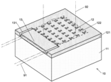
図1に、第1実施形態の回折格子結合器10を斜視図で示す。この回折格子結合器10は、二酸化ケイ素(SiO2)から成り平面形状が長方形である基台11と、基台11の表面に形成されたケイ素(Si)から成る長方形の板状の母材121と、母材121に設けられた空孔から成る多数の異屈折率領域122と、母材121の長方形の四辺のうちの一辺(後述する第1方向の起点側の端部)に設けられた入力ポート(光入力部)13とを備える。母材121と異屈折率領域122を合わせて回折格子12が構成されている。母材121の、基台11とは反対側の表面は空間(空気)である。 (1) First Embodiment FIG. 1 shows a perspective view of adiffraction grating coupler 10 according to a first embodiment. The diffraction grating coupler 10 comprises a base 11 made of silicon dioxide (SiO 2 ) and having a rectangular planar shape, and a rectangular plate-shaped base material 121 made of silicon (Si) formed on the surface of the base 11 . , a large number of modified refractive index regions 122 made up of holes provided in the base material 121, and one side of the rectangular four sides of the base material 121 (the end on the starting point side in the first direction described later) provided and an input port (optical input unit) 13 . The diffraction grating 12 is formed by combining the base material 121 and the modified refractive index region 122 . The surface of the base material 121 opposite to the base 11 is a space (air).
図1に、第1実施形態の回折格子結合器10を斜視図で示す。この回折格子結合器10は、二酸化ケイ素(SiO2)から成り平面形状が長方形である基台11と、基台11の表面に形成されたケイ素(Si)から成る長方形の板状の母材121と、母材121に設けられた空孔から成る多数の異屈折率領域122と、母材121の長方形の四辺のうちの一辺(後述する第1方向の起点側の端部)に設けられた入力ポート(光入力部)13とを備える。母材121と異屈折率領域122を合わせて回折格子12が構成されている。母材121の、基台11とは反対側の表面は空間(空気)である。 (1) First Embodiment FIG. 1 shows a perspective view of a
なお、本実施形態では母材121の下面全体を基台11で支持しているが、母材121の下面の一部(例えば母材121の長方形の対向する2辺付近のみ)を何らかの部材で支持するようにしてもよい。また、基台11及び母材121の材料は上記の例には限定されず、他の材料を用いてもよい。異屈折率領域122は空孔の代わりに、母材121とは屈折率が異なる材料から成る物を母材に埋め込んだものであってもよい。また、図1等では異屈折率領域122を数十個程度描いているが、実際にはさらに多くの異屈折率領域122が母材121に設けられている。
In the present embodiment, the entire lower surface of the base material 121 is supported by the base 11, but a part of the lower surface of the base material 121 (for example, only two opposite sides of the rectangle of the base material 121) is supported by some member. You can support it. Moreover, the materials of the base 11 and the base material 121 are not limited to the above examples, and other materials may be used. The modified refractive index region 122 may be formed by embedding a material having a refractive index different from that of the base material 121 in place of the holes. In addition, although several dozen modified refractive index regions 122 are depicted in FIG.
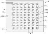
図2の上面図に示すように、個々の異屈折率領域122は、第1部分異屈折率領域1221と、第1部分異屈折率領域1221とは平面形状及び面積が異なる第2部分異屈折率領域1222が互いに離間して配置されて成る。それらの平面形状は、第1部分異屈折率領域1221は楕円形であって、第2部分異屈折率領域1222は円形である。このように第1部分異屈折率領域1221と第2部分異屈折率領域1222の平面形状及び面積が異なることにより、異屈折率領域122全体の平面形状は180°回転対称性を有していない。
As shown in the top view of FIG. 2, each of the modified refractive index regions 122 is a second partial modified refractive index region having a planar shape and area different from those of the first partial modified refractive index region 1221 and the first partial modified refractive index region 1221. Index regions 1222 are spaced apart from each other. As for their planar shapes, the first partial modified refractive index region 1221 is elliptical, and the second partial modified refractive index region 1222 is circular. Since the planar shape and area of the first partial modified refractive index region 1221 and the second partial modified refractive index region 1222 are different, the planar shape of the entire modified refractive index region 122 does not have 180° rotational symmetry. .
また、個々の異屈折率領域122の形状は、第1結合係数κ1と第2結合係数κ2の比|κ2|/|κ1|が3以上となるように設計されているが、その設計の詳細は後述する。本実施形態における第1結合係数κ1は、入力ポート13から、該入力ポート13が設けられた母材121の長方形の一辺の対辺に向かって進行する光(この光が進行する方向を「第1方向」とする。図2、図3において左から右に向かう方向である。)が、異屈折率領域122によって第1方向とは180°異なる方向(「第2方向」とする)に向かって反射される強度を示す指標である。第2結合係数κ2は、第2方向に進行する光が異屈折率領域122によって第1方向に向かって反射される強度を示す指標である。
The shape of each modified refractive index region 122 is designed so that the ratio |κ2|/|κ1| between the first coupling coefficient κ1 and the second coupling coefficient κ2 is 3 or more. will be described later. The first coupling coefficient κ1 in this embodiment is defined by the light traveling from the input port 13 toward the opposite side of the rectangle of the base material 121 on which the input port 13 is provided (the traveling direction of this light is the “first 2 and 3) is 180° different from the first direction by the modified refractive index region 122 (referred to as the “second direction”). It is an indicator of reflected intensity. The second coupling coefficient κ2 is an index that indicates the intensity with which light traveling in the second direction is reflected in the first direction by the modified refractive index region 122 .
なお、図2に示した例では、第1部分異屈折率領域1221の平面形状は楕円形、第2部分異屈折率領域1222の平面形状は円形としたが、それら部分異屈折率領域の平面形状はその他の形状としてもよい。また第2部分異屈折率領域1222は、平面形状及び面積のうちの一方のみを、第1部分異屈折率領域1221と異なるようにしてもよい。
In the example shown in FIG. 2, the planar shape of the first partial modified refractive index region 1221 is elliptical, and the planar shape of the second partial modified refractive index region 1222 is circular. Other shapes are also possible. Also, the second partial modified refractive index region 1222 may differ from the first partial modified refractive index region 1221 only in one of the planar shape and area.
異屈折率領域122は、長方形の母材121のうち該長方形の四辺付近を除く範囲内であって、長方格子の格子点上に1個ずつ配置されている。長方格子の2つの基本並進ベクトルは、一方が第1方向及び第2方向に平行に、他方が第1方向及び第2方向に垂直に向いている。長方格子の格子定数は、第1方向及び第2方向に垂直な方向の格子定数a2よりも、第1方向及び第2方向に平行な方向の格子定数a1の方が長くなるように設定されている。第1部分異屈折率領域1221の平面形状における短軸は第1方向及び第2方向に平行な方向を向いており、第1部分異屈折率領域1221の重心と第2部分異屈折率領域1222の重心は第1方向及び第2方向に平行な方向に離間している。
The modified refractive index regions 122 are arranged one by one on lattice points of the rectangular lattice within a range of the rectangular base material 121 excluding the vicinity of the four sides of the rectangle. The two primitive translation vectors of the rectangular lattice are oriented one parallel to the first and second directions and the other perpendicular to the first and second directions. The lattice constant of the rectangular lattice is such that the lattice constant a1 in the direction parallel to the first direction and the second direction is longer than the lattice constant a2 in the direction perpendicular to the first direction and the second direction. is set. The short axis of the planar shape of the first partial modified refractive index region 1221 is parallel to the first direction and the second direction, and the center of gravity of the first partial modified refractive index region 1221 and the second partial modified refractive index region 1222 are spaced apart in a direction parallel to the first and second directions.
図3の断面図に示すように、異屈折率領域122は、厚さ方向には母材121の上面側から所定の深さまで、母材121を貫通することなく設けられている。但し、本発明では、母材121を貫通するように異屈折率領域122を形成してもよいし、異屈折率領域122の上面に母材121と同じ材料から成る蓋を設けることにより母材121の内部にのみ異屈折率領域122を設けてもよい。
As shown in the cross-sectional view of FIG. 3, the modified refractive index region 122 is provided from the upper surface side of the base material 121 to a predetermined depth in the thickness direction without penetrating the base material 121 . However, in the present invention, the modified refractive index region 122 may be formed so as to penetrate the base material 121, or the base material may be The modified refractive index region 122 may be provided only inside 121 .
入力ポート13は、長方形の母材121のうち該長方形の一辺側の、異屈折率領域122が配置されていない(回折格子12が形成されていない)部分に設けられており、回折格子12から前記長方形の一辺に向かって延びる2本の溝131の間の部分が該当する。
The input port 13 is provided in a portion of the rectangular base material 121 on one side of the rectangle where the modified refractive index region 122 is not arranged (the diffraction grating 12 is not formed). This corresponds to the portion between the two grooves 131 extending toward one side of the rectangle.
入力ポート13の外側である母材121の端部には入力側光学要素91が、回折格子12の上面(基台11とは反対側の面)には出力側光学要素92が、それぞれ配置される。入力側光学要素91には光IC等を、出力側光学要素92には光ファイバ等を、それぞれ用いることができる。
An input-side optical element 91 is arranged on the end of the base material 121 outside the input port 13, and an output-side optical element 92 is arranged on the upper surface of the diffraction grating 12 (the surface opposite to the base 11). be. An optical IC or the like can be used for the input side optical element 91, and an optical fiber or the like can be used for the output side optical element 92, respectively.
本実施形態の回折格子結合器10の動作を説明する。回折格子結合器10を使用する際には、入力側光学要素91が発する入力光の進行方向が母材121に平行な方向となるように、入力側光学要素91を入力ポート13の端部に設置する。入力光には、入力光の進行方向における回折格子12の格子定数であるa1と同じ長さの波長を有するものを用いる。入力光の波長が予め定まっている場合には、その波長に合わせて格子定数a1を設定しておく。なお、ここで言う入力光の波長は回折格子12内における波長であって、回折格子12内の有効屈折率が1よりも大きいため、真空中における波長よりも短い。
The operation of the diffraction grating coupler 10 of this embodiment will be described. When using the diffraction grating coupler 10 , the input side optical element 91 is placed at the end of the input port 13 so that the traveling direction of the input light emitted by the input side optical element 91 is parallel to the base material 121 . Install. The input light used has a wavelength of the same length as a1 , which is the grating constant of the diffraction grating 12 in the traveling direction of the input light. When the wavelength of the input light is predetermined, the lattice constant a1 is set according to the wavelength. The wavelength of the input light referred to here is the wavelength within the diffraction grating 12, and is shorter than the wavelength in vacuum because the effective refractive index within the diffraction grating 12 is greater than 1.
入力ポート13から入力される入力光は、回折格子12内を第1方向に進行する。そして、入力光は回折格子12内において、周期的に配置されている異屈折率領域122によって回折される。このとき、回折格子12内での入力光の波長が入力光の進行方向の格子定数a1に一致していることから、母材121に垂直な方向に回折された回折光が干渉により強められる。その結果、母材121に垂直な方向に回折された回折光が出力光として、母材121の表面から取り出される(図3)。この表面に出力側光学要素92を(例えば、図1に示すように、出力側光学要素92である光ファイバの一端をこの表面に向けて)配置しておくことにより、出力光が出力側光学要素92に取り込まれる。こうして、回折格子結合器10により、入力側光学要素91と出力側光学要素92が光学的に結合される。
Input light input from the input port 13 travels in the diffraction grating 12 in the first direction. The input light is diffracted by the periodically arranged modified refractive index regions 122 in the diffraction grating 12 . At this time, since the wavelength of the input light in the diffraction grating 12 matches the grating constant a 1 in the traveling direction of the input light, the diffracted light diffracted in the direction perpendicular to the base material 121 is strengthened by interference. . As a result, the diffracted light diffracted in the direction perpendicular to the base material 121 is extracted from the surface of the base material 121 as output light (FIG. 3). By arranging an output-side optical element 92 on this surface (for example, as shown in FIG. 1, one end of an optical fiber, which is the output-side optical element 92, faces this surface), the output light is transferred to the output-side optical element. Captured in element 92 . Thus, the input side optical element 91 and the output side optical element 92 are optically coupled by the diffraction grating coupler 10 .
一方、回折格子12内を第1方向に進行する入力光の一部は、異屈折率領域122で反射し、第2方向に進行する反射光となる。しかし、本実施形態の回折格子結合器10では、第1結合係数κ1と第2結合係数κ2の比|κ2|/|κ1|が3以上となるように異屈折率領域122の形状及び大きさが設計されていることにより、反射光の強度はおおむね入射光の強度の10%以下に抑えられる。そのため、出力光の強度の低下を抑えて出力効率を高くすることができると共に、反射光が逆進入して入力側光学要素91が故障することを抑えることができる。
On the other hand, part of the input light traveling in the first direction inside the diffraction grating 12 is reflected by the modified refractive index region 122 and becomes reflected light traveling in the second direction. However, in the diffraction grating coupler 10 of the present embodiment, the shape and size of the modified refractive index region 122 are such that the ratio |κ2|/|κ1| between the first coupling coefficient κ1 and the second coupling coefficient κ2 is 3 or more. is designed, the intensity of the reflected light is generally suppressed to less than 10% of the intensity of the incident light. Therefore, it is possible to suppress the decrease in the intensity of the output light and increase the output efficiency, and it is possible to suppress the failure of the input side optical element 91 due to the reverse entrance of the reflected light.
以下、|κ2|/|κ1|が3以上となるように異屈折率領域122の形状及び大きさを設計した例を詳細に説明すると共に、設計した形状及び大きさの異屈折率領域122を用いた場合における出力光及び反射光をシミュレーションした結果を説明する。なお、以下で示す設計は一例であって、異屈折率領域が他の形状を有する場合にも、非特許文献2に記載の方法を用いて第1結合係数κ1及び第2結合係数κ2を計算したうえで|κ2|/|κ1|が3以上となるように適宜設計を行うことができる。
Hereinafter, an example in which the shape and size of the modified refractive index region 122 are designed so that |κ2|/|κ1| is 3 or more will be described in detail. The result of simulating the output light and the reflected light in the case of use will be described. The design shown below is an example, and even when the modified refractive index regions have other shapes, the first coupling coefficient κ1 and the second coupling coefficient κ2 are calculated using the method described in Non-Patent Document 2. Then, it is possible to appropriately design so that |κ2|/|κ1| is 3 or more.
この設計例で用いた、κ1及びκ2を定めるためのパラメータを、図4を参照しつつ説明する。母材121(Si)の屈折率は3.4、異屈折率領域122(空気)の屈折率は1とした。格子定数はa1=470nm、a2=316nmとした。母材121の厚さは330nm、異屈折率領域122の厚さは220nmとした。入力光・出力光の回折格子12内での波長はa1と同じ値の470nmである。なお、回折格子12の有効屈折率が異屈折率領域122の大きさに依存することから、入力光・出力光の真空中での波長も異屈折率領域122の大きさに依存して異なる。
Parameters for determining κ1 and κ2 used in this design example will be described with reference to FIG. The base material 121 (Si) has a refractive index of 3.4, and the modified refractive index region 122 (air) has a refractive index of 1. Lattice constants were a 1 =470 nm and a 2 =316 nm. The thickness of the base material 121 was 330 nm, and the thickness of the modified refractive index region 122 was 220 nm. The wavelength of the input light/output light within the diffraction grating 12 is 470 nm, which is the same value as a1 . Since the effective refractive index of the diffraction grating 12 depends on the size of the modified refractive index regions 122, the wavelengths of the input light and output light in vacuum also differ depending on the size of the modified refractive index regions 122. FIG.
第1部分異屈折率領域1221の重心と第2部分異屈折率領域1222の重心間の距離dは、0.260a1、0.265a1、0.270a1の3つの例を用意した。
Three examples of 0.260a 1 , 0.265a 1 and 0.270a 1 were prepared for the distance d between the center of gravity of the first partial modified refractive index region 1221 and the center of gravity of the second partial modified refractive index region 1222 .
第1部分異屈折率領域1221の平面形状と、第2部分異屈折率領域1222の平面形状は、第1部分異屈折率領域1221の充填率f1と第2部分異屈折率領域1222の充填率f2の和f=f1+f2が0.07(7%)となるように定めた。ここで第1(第2)部分異屈折率領域1221(1222)の充填率f1(f2)は、第1(第2)部分異屈折率領域1221(1222)の平面形状の面積を単位格子の面積(=a1×a2)で除した値で定義される。第1部分異屈折率領域1221の楕円形の長軸の長さは137nmに固定したうえで、第1部分異屈折率領域1221の充填率f1が3.75%、3.80%、3.85%、3.90%、3.95%の5つの例につき、異屈折率領域122の充填率fが7%となるように該楕円形の短軸の長さ及び第2部分異屈折率領域1222の円形の径を定めた。
The planar shape of the first partial modified refractive index region 1221 and the planar shape of the second partial modified refractive index region 1222 are determined by the filling factor f 1 of the first partial modified refractive index region 1221 and the filling rate f 1 of the second partial modified refractive index region 1222 . The sum f=f 1 +f 2 of the ratios f 2 was determined to be 0.07 (7%). Here, the filling factor f 1 (f 2 ) of the first (second) partial modified refractive index region 1221 (1222) is the planar area of the first (second) partial modified refractive index region 1221 (1222). Defined by the value divided by the grid area (=a 1 ×a 2 ). The length of the major axis of the ellipse of the first partial modified refractive index region 1221 is fixed to 137 nm, and the filling factor f 1 of the first partial modified refractive index region 1221 is 3.75%, 3.80%, 3.85%, and 3.90%. , 3.95%, the length of the minor axis of the ellipse and the circular diameter of the second partial modified refractive index region 1222 were determined so that the filling factor f of the modified refractive index region 122 was 7%. .
以上に述べた3個の重心間距離dの例と5個の第1部分異屈折率領域1221の充填率f1の例を組み合わせた15個の例につき、非特許文献2に記載の方法を用いて、第1結合係数κ1及び第2結合係数κ2を求めるためのエルミート結合係数R±iI及び非エルミート結合係数iμ(iは虚数単位)を求めた。
The method described in Non-Patent Document 2 is applied to 15 examples in which the three examples of the distance d between the centers of gravity described above and the examples of the filling factor f 1 of the five first partial modified refractive index regions 1221 are combined. were used to determine the Hermitian coupling coefficient R±iI and the non-Hermitian coupling coefficient iμ (i is an imaginary unit) for determining the first coupling coefficient κ1 and the second coupling coefficient κ2.
ここでエルミート結合係数R±iIは、図5中に「エルミート結合」と記載した枠内に示すように、損失を伴うことなく光の進行方向が180°変化する指標を示す係数である。エルミート結合係数は、第2方向から第1方向に変化するときの値(こちらをR+iIとする)と、第1方向から第2方向に変化するときの値(こちらをR-iIとする)が複素共役の関係にある。非エルミート結合係数iμは、図5中に「非エルミート結合」と記載した枠内に示すように、初期の方向から90°異なる方向(母材121に垂直な方向)への放射損失を伴いながら、該初期の方向とは180°異なる方向に光の進行方向が変化する指標を示す係数である。非エルミート結合係数は、第2方向から第1方向に変化するときの値と、第1方向から第2方向に変化するときの値が同じiμとなる。これら損失を伴うことなく進行方向が180°変化する光と、放射損失を伴いながら進行方向が180°変化する光の和が反射光となる。第1結合係数κ1及び第2結合係数κ2はそれぞれ、これらエルミート結合係数及び非エルミート結合係数を用いて
κ1=R-iI+iμ
κ2=R+iI+iμ
で表される。第1結合係数κ1及び第2結合係数κ2と、第1方向に伝播する光が第2方向に反射される反射率R1及び第2方向に伝播する光が第1方向に反射される反射率R2の関係は、
R1/R2=|κ1/κ2|2
となる。|κ2|/|κ1|が3以上のとき、R1/R2は1/9以下となり、入力波に対する反射率を概ね10%以下(厳密には11.1…%以下)に抑えることができる。 Here, the Hermitian coupling coefficient R±iI is a coefficient indicating an index that changes the traveling direction of light by 180° without loss, as shown in the frame labeled "Hermitian coupling" in FIG. The Hermitian coupling coefficient has a value when changing from the second direction to the first direction (this is R+iI) and a value when changing from the first direction to the second direction (this is R-iI). They have a complex conjugate relationship. The non-Hermitian coupling coefficient iμ, as shown in the frame labeled "non-Hermitian coupling" in FIG. , is a coefficient that indicates an index for changing the traveling direction of light in a direction different from the initial direction by 180°. The non-Hermitian coupling coefficient has the same value iμ when changing from the second direction to the first direction and the value when changing from the first direction to the second direction. Reflected light is the sum of the light whose traveling direction changes by 180° without loss and the light whose traveling direction changes by 180° with radiation loss. The first coupling coefficient κ1 and the second coupling coefficient κ2 are obtained using these Hermitian and non-Hermitian coupling coefficients, respectively, κ1=R−iI+iμ
κ2 = R + iI + iμ
is represented by A first coupling coefficient κ1 and a second coupling coefficient κ2, a reflectance R1 at which the light propagating in the first direction is reflected in the second direction, and a reflectance R2 at which the light propagating in the second direction is reflected in the first direction The relationship between
R1/R2=|κ1/κ2| 2
becomes. When |κ2|/|κ1| is 3 or more, R1/R2 becomes 1/9 or less, and the reflectance for the input wave can be suppressed to approximately 10% or less (strictly speaking, 11.1% or less).
エルミート結合係数R±iIにおけるR及びIの値を計算した結果を図6に示す。非エルミート結合係数の虚部(実部は0)を表す値μの計算結果は、重心間距離d及び第1部分異屈折率領域の充填率f1にはほとんど依存せず、ほぼ同じ値(約70cm-1)であった。図6中に示した17個のデータ点のうち、破線の矢印で指した2個を除く15個のデータ点が、前述した重心間距離dと第1部分異屈折率領域1221の充填率f1を組み合わせた15個の例の各々に係るR及びIの値を示す。各データ点における重心間距離d及び第1部分異屈折率領域1221の充填率f1の値は、各データ点付近において交差する細破線の曲線上に記載した数値が対応する。破線の矢印で指した2個のデータは、それぞれR=0, I=+μ、及びR=0, I=-μとなる点であって、前者は反射光の強度が0になるときのR, I、後者は反射光の強度が1になるときのR, Iを示している。図6中に太破線で示した円内(d=0.265a1, f1=3.75%、及びd=0.265a1, f1=3.80%)のデータ点において、|κ2|/|κ1|が3以上となる。
FIG. 6 shows the results of calculating the values of R and I in the Hermitian coupling coefficient R±iI. The calculation result of the value μ representing the imaginary part (the real part is 0) of the non-Hermitian coupling coefficient is almost the same value (approximately 70 cm -1 ). Of the 17 data points shown in FIG. 6, 15 data points, excluding the two indicated by the dashed arrows, correspond to the distance d between the centers of gravity and the filling factor f of the first partial modified refractive index region 1221. Values of R and I for each of the 15 examples of combinations of 1 are shown. The values of the center-of-gravity distance d and the filling factor f 1 of the first partial modified refractive index region 1221 at each data point correspond to the numerical values described on the curves of thin dashed lines that intersect in the vicinity of each data point. The two data points indicated by the dashed arrows are the points where R = 0, I = +μ and R = 0, I = -μ, respectively. , I, and the latter shows R, I when the intensity of the reflected light is 1. | κ2 | / | κ1 | 3 or more.
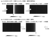
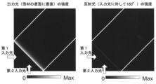
図7に、|κ2|/|κ1|が3以上であるd=0.265a1, f1=3.80%の場合について、母材121に垂直な方向に出力される出力光、及び回折格子12内で反射されて進行方向が180°変化した反射光の強度分布を計算で求めた結果を示す。こででは、入力ポート13から入力光を入力した(入力光が第1方向に進行する)通常の場合(a)と、参考として入力ポート13とは反対側の母材121の端部から入力光を入力した(入力光が第2方向に進行する)場合(b)の2つの場合について計算を行った。
FIG. 7 shows the output light output in the direction perpendicular to the base material 121 and the output light in the diffraction grating 12 when |κ2|/|κ1| Calculation results of the intensity distribution of the reflected light whose traveling direction is changed by 180° are shown. Here, the normal case (a) in which the input light is input from the input port 13 (the input light travels in the first direction) and the input from the end of the base material 121 opposite to the input port 13 are shown for reference. Calculations were performed for two cases (b) when light is input (input light travels in the second direction).
その結果、入力ポート13から光を入力した場合には、回折格子12の入力ポート13側の端部(図7(a)の左図に縦向きの矢印を付した箇所)から回折格子12内に亘って、母材121に垂直な方向に出力光が出力されているのに対して、反射光はほとんど発生していない(図7(a)の右図。同図中の破線部が回折格子12の入力ポート13側の端部。)ことがわかる。この結果から、d=0.265a1, f1=3.80%の場合において、第1実施形態の回折格子結合器10は、入力ポート13から入力した光を母材121に垂直な方向に効率よく出力できることがわかる。
As a result, when the light is input from the input port 13, the light inside the diffraction grating 12 from the end of the diffraction grating 12 on the input port 13 side (the location indicated by the vertical arrow in the left diagram of FIG. 7A). While the output light is emitted in the direction perpendicular to the base material 121, almost no reflected light is generated (the right diagram of FIG. 7(a). The dashed line in the diagram indicates the diffraction the end of the grid 12 facing the input port 13). From this result, when d=0.265a 1 , f 1 =3.80%, the diffraction grating coupler 10 of the first embodiment efficiently outputs the light input from the input port 13 in the direction perpendicular to the base material 121. I know you can.
一方、入力ポート13の反対側から光を入力した場合には、入力ポート13とは反対側の回折格子12の端部(図7(b)の右図に縦向きの矢印を付した箇所)及び該端部からやや回折格子12内に入った領域においてほとんどの入力光が反射されており、母材121に垂直な方向には光がほとんど出力されていないことがわかる。
On the other hand, when the light is input from the side opposite to the input port 13, the end of the diffraction grating 12 opposite to the input port 13 (the portion indicated by the vertical arrow in the right figure of FIG. 7(b)) And, it can be seen that most of the input light is reflected in the region slightly inside the diffraction grating 12 from the edge, and almost no light is output in the direction perpendicular to the base material 121 .
ここまでは、第1部分異屈折率領域1221と第2部分異屈折率領域1222の対から成る異屈折率領域122を用いた場合を例に説明したが、|κ2|/|κ1|が3以上であるという条件を満たす平面形状であれば、母材121とは屈折率が異なる1個のみの領域から成る異屈折率領域を用いてもよいし、3個以上の部分異屈折率領域から成る異屈折率領域を用いてもよい。
Up to this point, the case of using the modified refractive index region 122 consisting of a pair of the first partial modified refractive index region 1221 and the second partial modified refractive index region 1222 has been described as an example. As long as the planar shape satisfies the above conditions, a modified refractive index region consisting of only one region having a refractive index different from that of the base material 121 may be used, or three or more partial modified refractive index regions may be used. You may use the modified refractive index area|region which consists of.
また、ここまでは点状の異屈折率領域122を2次元状に配置した例を示したが、図8に示すように、点状の異屈折率領域122を1次元状に配置してもよい。この例では、母材121の面内において異屈折率領域122が並ぶ方向に対して垂直な方向(回折格子13の側方)に光が漏れることを防ぐために、入力ポート13から延びる2本の溝131を、異屈折率領域122が配置されていない部分のみならず、(回折格子12が形成されていない)部分回折格子13の側方(図8では回折格子13の上下)まで延ばして設けている。
Further, although an example in which the dot-like modified refractive index regions 122 are two-dimensionally arranged has been shown so far, as shown in FIG. good. In this example, in order to prevent light from leaking in the direction perpendicular to the direction in which the modified refractive index regions 122 are arranged in the plane of the base material 121 (toward the side of the diffraction grating 13), two light beams extending from the input port 13 are provided. The grooves 131 are provided to extend not only to the portion where the modified refractive index region 122 is not arranged, but also to the sides of the partial diffraction grating 13 (where the diffraction grating 12 is not formed) (above and below the diffraction grating 13 in FIG. 8). ing.
異屈折率領域122は図1等に示した例と同様に、楕円形の第1部分異屈折率領域1221と円形の第2部分異屈折率領域1222を組み合わせた形状を有し、各異屈折率領域122では第1部分異屈折率領域1221が第2部分異屈折率領域1222よりも入力ポート13側に配置されており、第1部分異屈折率領域1221の楕円形の短軸が溝131に平行な方向を向いている。
Similar to the example shown in FIG. In the index area 122 , the first partial modified refractive index area 1221 is arranged closer to the input port 13 than the second partial modified refractive index area 1222 , and the minor axis of the elliptical shape of the first partial modified refractive index area 1221 is the groove 131 . is oriented parallel to
図8に示した例では、2本の溝131の間の1次元状、言い換えれば導波路状の部分を光が通過する間に、その母材121に垂直な方向に光が出力される。以下では、このような導波路状の構造を有する回折格子結合器を「導波路型回折格子結合器」と呼ぶ。
In the example shown in FIG. 8, the light is output in a direction perpendicular to the base material 121 while the light passes through the one-dimensional shape between the two grooves 131, in other words, the waveguide-like portion. A diffraction grating coupler having such a waveguide-like structure is hereinafter referred to as a "waveguide-type diffraction grating coupler".
図8に示した導波路型回折格子結合器につき、以下の計算を行った。この計算では、異屈折率領域122の周期長(配置間隔)aは0.720μm、母材121の材質はSi(屈折率3.4)、2本の溝の間の母材121の幅wは0.480μm、母材121の厚さは0.22μmとした。また、第1部分異屈折率領域1221の面積S1と第2部分異屈折率領域1222の面積S2の和S=S1+S2は0.08a2とした。これにより、異屈折率領域122の充填率はf=S/(a×w)=0.08a/w=0.12となる。第1部分異屈折率領域1221の楕円率は10S1/a2とした。このような異屈折率領域122を1次元状に150個配置した例で計算を行った。
The following calculations were performed for the waveguide type diffraction grating coupler shown in FIG. In this calculation, the periodic length (arrangement interval) a of the modified refractive index regions 122 is 0.720 μm, the material of the base material 121 is Si (refractive index 3.4), and the width w of the base material 121 between the two grooves is 0.480 μm. , and the thickness of the base material 121 is 0.22 μm. The sum S = S 1 +S 2 of the area S 1 of the first partial modified refractive index region 1221 and the area S 2 of the second partial modified refractive index region 1222 was 0.08a 2 . As a result, the filling factor of the modified refractive index region 122 is f=S/(a×w)=0.08a/w=0.12. The ellipticity of the first partial modified refractive index region 1221 was set to 10S 1 /a 2 . Calculation was performed with an example in which 150 such modified refractive index regions 122 were arranged one-dimensionally.
まず、第1部分異屈折率領域1221の重心と第2部分異屈折率領域1222の重心の間の距離(重心間距離)dを0.286aとし、第1部分異屈折率領域1221の面積S1を0.0440a2とした場合(第1の例の導波路型回折格子結合器)について、エルミート結合係数の実部R及び虚部I、並びに非エルミート結合係数の虚部μ(実部は0)を求めたところ、I≒μ≒350cm-1となり、Rの絶対値はI及びμよりも十分に小さい値(|R|<50cm-1)となった。これらR、I及びμより、第1結合係数κ1=R-iI+iμの絶対値|κ1|は第2結合係数κ2=R+iI+iμの絶対値|κ2|よりも十分に小さくなる。そのため、第1の例の導波路型回折格子結合器では|κ2|/|κ1|が3以上という要件を満たす。
First, the distance (center-to-center distance) d between the center of gravity of the first partial modified refractive index region 1221 and the center of gravity of the second partial modified refractive index region 1222 is set to 0.286a, and the area S 1 of the first partial modified refractive index region 1221 is is 0.0440a 2 (waveguide grating coupler of the first example), the real part R and the imaginary part I of the Hermitian coupling coefficient and the imaginary part μ of the non-Hermitian coupling coefficient (the real part is 0) was found to be I≈μ≈350 cm −1 , and the absolute value of R was sufficiently smaller than I and μ (|R|<50 cm −1 ). From these R, I and μ, the absolute value |κ1| of the first coupling coefficient κ1=R−iI+iμ is sufficiently smaller than the absolute value |κ2| of the second coupling coefficient κ2=R+iI+iμ. Therefore, the waveguide grating coupler of the first example satisfies the requirement that |κ2|/|κ1| is 3 or more.
第1の例の導波路型回折格子結合器につき、入力ポート13から入力された光(入力光)が、母材121に垂直な方向に放出される放出光、異屈折率領域122により反射されて入力ポート13側に戻る反射光、及び回折格子を透過して入力ポート13の反対側の導波路端部に流出する透過光の強度を計算で求めた。その結果を図9(a)に示す。同図に示すように、入力ポート13から光を入力するという通常の使用法により、計算を行った規格化周波数の範囲(0.45~0.50)の全体に亘って入力光のほとんどが反射又は透過することなく出力され、回折格子結合器として機能することがわかる。ここで規格化周波数にc/a(cは光速)を乗じたものが、周期長がaである導波路型回折格子結合器における光の周波数を表す。
In the waveguide type diffraction grating coupler of the first example, light (input light) input from the input port 13 is emitted in a direction perpendicular to the base material 121 and reflected by the modified refractive index region 122. The intensity of the reflected light returning to the input port 13 side and the intensity of the transmitted light passing through the diffraction grating and flowing out to the waveguide end on the opposite side of the input port 13 were obtained by calculation. The results are shown in FIG. 9(a). As shown in the figure, most of the input light is reflected or transmitted over the entire calculated normalized frequency range (0.45 to 0.50) due to the normal usage of inputting light from the input port 13. It can be seen that it functions as a diffraction grating coupler. Here, the normalized frequency multiplied by c/a (where c is the speed of light) represents the frequency of light in a waveguide grating coupler with a periodic length of a.
併せて、参考のため、入力ポート13の反対側の導波路端部から光を入力した場合の放出光、反射光(前記導波路端部に戻る光)及び透過光(入力ポート13に流出する光)の強度を計算で求めた結果を図9(b)に示す。この場合には、規格化周波数が0.475前後(図9において破線で囲んだ領域)において強い反射光が生じ、回折格子結合器としては十分に機能しないことがわかる。なお、この場合には図9(a)に示した構成を反射器として使用することができる。
In addition, for reference, emitted light, reflected light (light returning to the waveguide end) and transmitted light (flowing out to the input port 13) when light is input from the waveguide end on the opposite side of the input port 13 FIG. 9(b) shows the result of calculating the intensity of light). In this case, strong reflected light occurs at a normalized frequency of around 0.475 (the area surrounded by the dashed line in FIG. 9), indicating that the diffraction grating coupler does not function satisfactorily. In this case, the structure shown in FIG. 9(a) can be used as a reflector.
次に、比較例の導波路型回折格子結合器として、第1部分異屈折率領域1221の面積S1を0.0475a2とし、それ以外のパラメータを第1の例と同じ値とした場合につき、エルミート結合係数の実部R及び虚部I、並びに非エルミート結合係数の虚部μを求めたところ、I≒-350cm-1、μ≒-350cm-1、|R|<50cm-1となった。これらR、I及びμより、第1結合係数κ1=R-iI+iμの絶対値|κ1|は第2結合係数κ2=R+iI+iμの絶対値|κ2|よりも十分に大きくなる。そのため、この比較例の導波路型回折格子結合器では|κ2|/|κ1|が3以上という要件を満たさず、逆に|κ1|/|κ2|が3以上(|κ2|/|κ1|は3未満)となる。
Next, as a waveguide type diffraction grating coupler of a comparative example, when the area S1 of the first partial modified refractive index region 1221 is set to 0.0475a 2 and the other parameters are set to the same values as in the first example, The real part R and imaginary part I of the Hermitian coupling coefficient and the imaginary part μ of the non-Hermitian coupling coefficient were obtained . . From these R, I and μ, the absolute value |κ1| of the first coupling coefficient κ1=R−iI+iμ becomes sufficiently larger than the absolute value |κ2| of the second coupling coefficient κ2=R+iI+iμ. Therefore, the waveguide grating coupler of this comparative example does not satisfy the requirement that |κ2|/|κ1| is less than 3).
この比較例の導波路型回折格子結合器につき、入力ポート13側(異屈折率領域122の第1部分異屈折率領域1221側)から光を入射した場合(図10(a))と、入力ポート13の反対側(第2部分異屈折率領域1222側)から光を入射した場合(図10(b))における出力光、反射光及び透過光の強度を計算で求めた。その結果、図10(a)に示すように、入力ポート13側から0.475前後の規格化周波数を有する入力光を入力した場合には、反射光の強度が大きくなり、導波路型回折格子結合器として必要な特性が得られないことがわかる。なお、|κ1|/|κ2|が3以上であることから、第1方向と第2方向を入れ替えると結合係数の比が3以上であるという要件を満たすため、入力ポート13の反対側から入力光を入力した場合には、このような反射はほとんど生じない。
For the waveguide type diffraction grating coupler of this comparative example, when light is incident from the input port 13 side (the first partial modified refractive index region 1221 side of the modified refractive index region 122) (FIG. 10(a)) and the input The intensities of output light, reflected light, and transmitted light when light is incident from the opposite side of the port 13 (second partial modified refractive index region 1222 side) (FIG. 10(b)) were obtained by calculation. As a result, as shown in FIG. 10(a), when input light having a normalized frequency of around 0.475 is input from the input port 13 side, the intensity of the reflected light increases and the waveguide type diffraction grating coupler It can be seen that the required characteristics cannot be obtained as Since |κ1|/|κ2| is 3 or more, if the first direction and the second direction are switched, the ratio of the coupling coefficients is 3 or more. When light is input, such reflection hardly occurs.
そこで、図11に示すように、図8の例における入力ポート13とは反対側の導波路端部を新たな入力ポート13Aとし、図8の例における入力ポート13側を入力ポート13Aとは反対側の導波路端部とした構成において、回折格子12が上記比較例の導波路型回折格子結合器12と同様の構成とした、第2の例の導波路型回折格子結合器を導入する。この例では、入力ポート13A側(第2部分異屈折率領域1222側)から光を入射した場合に、反射や透過がほとんど生じることなく出力され、回折格子結合器として機能することがわかる(図10(b))。
Therefore, as shown in FIG. 11, the waveguide end on the side opposite to the input port 13 in the example of FIG. 8 is made a new input port 13A, and the input port 13 side in the example of FIG. A waveguide grating coupler of a second example is introduced in which the diffraction grating 12 has the same configuration as the waveguide grating coupler 12 of the comparative example in the configuration of the waveguide end on the side. In this example, when light enters from the input port 13A side (the second partial modified refractive index region 1222 side), it is output with almost no reflection or transmission, and it can be seen that it functions as a diffraction grating coupler (Fig. 10(b)).
ここまでは点状の異屈折率領域122を用いた例を示したが、線状の異屈折率領域を用いてもよい。図12に示す回折格子結合器10Aは、互いに幅が異なる溝によって形成された第1部分異屈折率領域1221Aと第2部分異屈折率領域1222Aから成る線状の異屈折率領域122Aを多数、該溝の幅方向に周期長aで1次元状に配置して成る回折格子12Aを備えている。第1部分異屈折率領域1221Aと第2部分異屈折率領域1222Aの幅を調整することにより、|κ2|/|κ1|を3以上に設定することができる。溝(部分異屈折率領域)の本数は3本以上であってもよい。
An example using the dot-shaped modified refractive index regions 122 has been shown so far, but a linear modified refractive index region may be used. The diffraction grating coupler 10A shown in FIG. 12 has a large number of linear modified refractive index regions 122A each composed of a first partial modified refractive index region 1221A and a second partial modified refractive index region 1222A formed by grooves having different widths. A diffraction grating 12A is arranged one-dimensionally with a periodic length a in the width direction of the groove. |κ2|/|κ1| can be set to 3 or more by adjusting the widths of the first partial modified refractive index region 1221A and the second partial modified refractive index region 1222A. The number of grooves (partially modified refractive index regions) may be three or more.
第1実施形態の回折格子結合器の変形例として、図13に示すように、回折格子12の母材121の表面(図13(a))又は内部(同(b))に、光増幅層(活性層)15を設けてもよい。光増幅層15には、レーザ素子等で用いられる通常の活性層であって、回折格子12内における波長が第1方向に関する異屈折率領域の周期長a1の整数倍又は整数分の1となる光を増幅するものを用いる。このような光増幅層15を備える回折格子結合器10Bは、入力光を光増幅層によって増幅させたうえで高い効率で出力する光増幅器として機能する。
As a modification of the diffraction grating coupler of the first embodiment, as shown in FIG. 13, a light amplification layer is provided on the surface (FIG. 13(a)) or inside (FIG. 13(b)) of the base material 121 of the diffraction grating 12. (Active layer) 15 may be provided. The light amplification layer 15 is a normal active layer used in a laser element or the like, and the wavelength in the diffraction grating 12 is an integer multiple or an integer fraction of the periodic length a1 of the modified refractive index region in the first direction. Use something that amplifies light. The diffraction grating coupler 10B having such an optical amplification layer 15 functions as an optical amplifier that amplifies input light by the optical amplification layer and outputs the amplified light with high efficiency.
ここまでに示した各例では、母材11に2本の溝131を形成してそれらの間の領域を入力ポート13としているが、溝131は省略してもよい。
In each example shown so far, two grooves 131 are formed in the base material 11 and the area between them is used as the input port 13, but the grooves 131 may be omitted.
(2) 第2実施形態
図14に、第2実施形態の回折格子結合器20の上面図を示す。この回折格子結合器20は、SiO2製の基台(図示せず。第1実施形態における基台11と同様。)上に設けられたSi製の板状の母材221と、該母材221に周期長aで正方格子状に配置された異屈折率領域222から成る回折格子22を備える。この正方格子における2つの基本並進ベクトルの方向のうちの一方をx方向、他方をy方向とする。異屈折率領域222は、平面形状が楕円形である第1部分異屈折率領域2221と、平面形状が円形である第2部分異屈折率領域2222の対から成る。第1部分異屈折率領域2221の楕円の短軸はx方向に対して+45°(xが増加するに伴ってyも増加する方向)傾斜した方向を向いており、第1部分異屈折率領域2221の重心と第2部分異屈折率領域2222の重心はこの短軸の方向に離間している。 (2) Second Embodiment FIG. 14 shows a top view of adiffraction grating coupler 20 according to a second embodiment. This diffraction grating coupler 20 includes a plate-like base material 221 made of Si provided on a base made of SiO 2 (not shown, similar to the base 11 in the first embodiment), and the base material 221 is provided with a diffraction grating 22 composed of modified refractive index regions 222 arranged in a square lattice with a periodic length a. Let one of the directions of the two basic translation vectors in this square lattice be the x-direction and the other be the y-direction. The modified refractive index region 222 is composed of a pair of a first partial modified refractive index region 2221 having an elliptical planar shape and a second partial modified refractive index region 2222 having a circular planar shape. The minor axis of the ellipse of the first partial modified refractive index region 2221 is inclined +45° (the direction in which y increases as x increases) with respect to the x direction, and the first partial modified refractive index The center of gravity of the region 2221 and the center of gravity of the second partial modified refractive index region 2222 are separated in the direction of this minor axis.
図14に、第2実施形態の回折格子結合器20の上面図を示す。この回折格子結合器20は、SiO2製の基台(図示せず。第1実施形態における基台11と同様。)上に設けられたSi製の板状の母材221と、該母材221に周期長aで正方格子状に配置された異屈折率領域222から成る回折格子22を備える。この正方格子における2つの基本並進ベクトルの方向のうちの一方をx方向、他方をy方向とする。異屈折率領域222は、平面形状が楕円形である第1部分異屈折率領域2221と、平面形状が円形である第2部分異屈折率領域2222の対から成る。第1部分異屈折率領域2221の楕円の短軸はx方向に対して+45°(xが増加するに伴ってyも増加する方向)傾斜した方向を向いており、第1部分異屈折率領域2221の重心と第2部分異屈折率領域2222の重心はこの短軸の方向に離間している。 (2) Second Embodiment FIG. 14 shows a top view of a
異屈折率領域222の形状は、+x方向(図14の左から右に向かう方向)を第1方向、-x方向(同図の右から左に向かう方向)を第2方向、+y方向(同図の下から上に向かう方向)を第3方向、-y方向(同図の上から下に向かう方向)を第4方向としたときに、第1方向及び第3方向に同位相・同振幅となるように進行する光のうち、第2方向及び第4方向に同位相・同振幅で反射される光の強度を示す指標である第1結合係数κ1に対する、第2方向及び第4方向に同位相・同振幅となるように進行する光のうち、第1方向及び第3方向に同位相・同振幅で反射される光の強度を示す指標である第2結合係数κ2の比|κ2|/|κ1|が3以上となるように設定されている。
The shape of the modified refractive index region 222 is such that the +x direction (direction from left to right in FIG. 14) is the first direction, the -x direction (direction from right to left in FIG. 14) is the second direction, and the +y direction. Assuming that (the direction from the bottom to the top of the figure) is the third direction and the -y direction (the direction from the top to the bottom of the figure) is the fourth direction, the first and third directions are in phase with each other. Among the lights traveling with the same amplitude, the second direction and the fourth The ratio of the second coupling coefficient κ2, which is an index indicating the intensity of the light reflected in the first direction and the third direction with the same phase and the same amplitude, among the lights traveling in the same phase and the same amplitude in the direction | κ2|/|κ1| is set to be 3 or more.
異屈折率領域222の形状の詳細な設計は後述する。
The detailed design of the shape of the modified refractive index region 222 will be described later.
母材221には、x方向に対して+45°傾斜し互いに平行である2本の溝(第1外縁溝241、第2外縁溝242)が形成されており、異屈折率領域222は第1外縁溝241と第2外縁溝242の間に設けられている。また、母材221には、第1外縁溝241のx方向の負側の一端から-x方向に延びる第1入力ポート溝2331と、第2外縁溝242のx方向の負側の一端から-y方向に延びる第2入力ポート溝2332が設けられている。さらに、母材221には、第1入力ポート溝2331に平行であって-y方向に離間して配置された溝と、第2入力ポート溝2332に平行であって-x方向に離間して配置された溝が接続されて成る第3入力ポート溝2333が設けられている。第1入力ポート溝2331と第3入力ポート溝2333の間の領域は第1入力ポート231、第2入力ポート溝2332と第3入力ポート溝2333の間の領域は第2入力ポート232として機能する。
In the base material 221, two grooves (first outer edge groove 241 and second outer edge groove 242) inclined +45° with respect to the x direction and parallel to each other are formed. It is provided between the first outer edge groove 241 and the second outer edge groove 242 . The base material 221 also has a first input port groove 2331 extending in the -x direction from one end of the first outer edge groove 241 on the negative side in the x direction, and a - input port groove 2331 extending in the -x direction from one end of the second outer edge groove 242 on the negative side in the x direction. A second input port groove 2332 is provided that extends in the y-direction. Further, in the base material 221, there are grooves parallel to the first input port groove 2331 and spaced apart in the -y direction, and parallel to the second input port groove 2332 and spaced apart in the -x direction. A third input port groove 2333 is provided which is formed by connecting the disposed grooves. The area between the first input port groove 2331 and the third input port groove 2333 functions as the first input port 231, and the area between the second input port groove 2332 and the third input port groove 2333 functions as the second input port 232. .
第1入力ポート231における母材221の端部には第1の入力側光学要素を配置し、第2入力ポート232における母材221の端部には第2の入力側光学要素を配置する。また、回折格子22の上面には出力側光学要素を配置する(いずれも図示省略)。これらの光学要素はいずれも、回折格子22における波長がaとなる光を入力/出力する。
A first input-side optical element is arranged at the end of the base material 221 at the first input port 231 , and a second input-side optical element is arranged at the end of the base material 221 at the second input port 232 . Also, an output-side optical element is arranged on the upper surface of the diffraction grating 22 (not shown). All of these optical elements input/output light having a wavelength a at the diffraction grating 22 .
第2実施形態の回折格子結合器20の動作を説明する。第1入力ポート231には、第1の入力側光学要素から、+x方向に進行する第1入力光が入力される。また、第2入力ポート232には、第2の入力側光学要素から、+y方向に進行する第2入力光が入力される。第1入力光及び第2入力光はいずれも回折格子22内に導入され、回折格子22によって母材221に垂直な方向に回折され、出力光として回折格子22の表面から取り出される。こうして取り出された出力光は、出力側光学要素に導入される。
The operation of the diffraction grating coupler 20 of the second embodiment will be explained. A first input light traveling in the +x direction is input to the first input port 231 from the first input side optical element. Also, the second input light traveling in the +y direction is input to the second input port 232 from the second input side optical element. Both the first input light and the second input light are introduced into the diffraction grating 22, diffracted by the diffraction grating 22 in a direction perpendicular to the base material 221, and extracted from the surface of the diffraction grating 22 as output light. The output light extracted in this way is introduced into the output-side optical element.
なお、第1入力ポート231からの入射光1のうちyの負側の端部付近から入射する光、及び第2入力ポート232からの入射光2のうちxの負側の端部付近から入射する光は、回折格子22内を進行する経路上に異屈折率領域222が十分な個数だけ存在しないため、一部が回折格子22を通過してしまうおそれがある。このような光を反射させることによって光が回折格子22を通過することを防ぐために、第1外縁溝241及び第2外縁溝242が設けられている。
Of the incident light 1 from the first input port 231, light incident near the negative end of y, and of the incident light 2 from the second input port 232, incident near the negative end of x Since a sufficient number of the modified refractive index regions 222 are not present on the path traveling through the diffraction grating 22 , part of the light may pass through the diffraction grating 22 . A first outer edge groove 241 and a second outer edge groove 242 are provided to prevent light from passing through the diffraction grating 22 by reflecting such light.
以下、|κ2|/|κ1|が3以上となるように異屈折率領域222の形状及び大きさを設計した例を詳細に説明する。
An example in which the shape and size of the modified refractive index region 222 are designed so that |κ2|/|κ1| is 3 or more will be described in detail below.
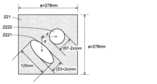
この設計例で用いた、κ1及びκ2を定めるためのパラメータを、図15を参照しつつ説明する。母材121(Si)の屈折率は3.4、異屈折率領域222(空気)の屈折率は1とした。格子定数はa=278nmとした。第1部分異屈折率領域2221の重心と第2部分異屈折率領域2222の重心は、x方向及びy方向にそれぞれ距離dだけ離間している。この距離dは、0.266a、0.272a、0.278a、0.284aの4つの例を用意した。第1部分異屈折率領域2221の楕円の長軸の長さは125nmに固定したうえで、短軸の長さは(53+2x)nm、第2部分異屈折率領域2222の円の直径は(67-2x)mmとし、2x=1.5nm、3.0nm、4.5nm、6.0nmの4つの例を用意した。
The parameters for determining κ1 and κ2 used in this design example will be explained with reference to FIG. The base material 121 (Si) has a refractive index of 3.4, and the modified refractive index region 222 (air) has a refractive index of 1. The lattice constant was set to a=278 nm. The center of gravity of the first partial modified refractive index region 2221 and the center of gravity of the second partial modified refractive index region 2222 are separated by a distance d in the x and y directions, respectively. Four examples of 0.266a, 0.272a, 0.278a, and 0.284a are prepared for this distance d. The length of the major axis of the ellipse of the first partial modified refractive index region 2221 is fixed to 125 nm, the length of the minor axis is (53+2x) nm, and the diameter of the circle of the second partial modified refractive index region 2222 is (67-2x) mm, and four examples of 2x=1.5 nm, 3.0 nm, 4.5 nm, and 6.0 nm were prepared.
以上に述べた4個の距離dの例と4個の2xの例を組み合わせた16個の例につき、非特許文献2に記載の方法を用いて、第1結合係数κ1及び第2結合係数κ2を求めるためのエルミート結合係数R±iI及び非エルミート結合係数iμを求めた。計算結果を図16に示す。非エルミート結合係数の虚部(実部は0)を表す値μの計算結果は、重心間距離d並びに第1部分異屈折率領域2221の楕円の短軸及び第2部分異屈折率領域2222の径を定める値である2xにはほとんど依存せず、ほぼ同じ値(約87cm-1)であった。図16中に示した18個のデータ点のうち、破線の矢印で指した2個を除く16個のデータ点が、上記16個の例の計算結果を示している。破線の矢印で指した2個のデータ点は、それぞれR=0, I=+μ、及びR=0, I=-μとなる点であって、前者は反射光の強度が0になるときのR, I、後者は反射光の強度が1になるときのR, Iを示している。図16中のに太破線で示した円内のデータ点(d=0.272a, 2x=1.5nm、及びd=0.278a, 2x=1.5nm)において、|κ2|/|κ1|が3以上となる。
Using the method described in Non-Patent Document 2, the first coupling coefficient κ1 and the second coupling coefficient κ2 The Hermitian coupling coefficient R±iI and the non-Hermitian coupling coefficient iμ for obtaining . Calculation results are shown in FIG. The calculation result of the value μ representing the imaginary part (the real part is 0) of the non-Hermitian coupling coefficient is the distance d between the centers of gravity, the short axis of the ellipse of the first partial modified refractive index region 2221, and the It was almost the same value (approximately 87 cm -1 ), almost independent of 2x, which is the value that determines the diameter. Of the 18 data points shown in FIG. 16, 16 data points excluding the two indicated by dashed arrows indicate the calculation results of the above 16 examples. The two data points indicated by dashed arrows are R=0, I=+μ and R=0, I=-μ, respectively. R, I, the latter shows R, I when the intensity of the reflected light is 1. |κ2|/|κ1| Become.
図17に、d=0.278a, 2x=1.5nmの場合について、母材221に垂直な方向に出力される出力光、及び回折格子22内で反射されて進行方向が180°変化した反射光の強度分布を計算で求めた結果を示す。第1入力ポート231から第1入力光を、第2入力ポート232から第2入力光を、それぞれ入力すると、回折格子22から母材221に垂直な方向に出力光が出力されている(図17の左図)のに対して、反射光はほとんど発生していない(同右図)ことがわかる。この結果から、d=0.278a, 2x=1.5nmの場合において、第2実施形態の回折格子結合器20は、第1入力ポート231及び第2入力ポート232から入力した光を母材221に垂直な方向に効率よく出力できることがわかる。
FIG. 17 shows the output light output in the direction perpendicular to the base material 221 and the reflected light whose traveling direction is changed by 180° after being reflected in the diffraction grating 22 when d=0.278a and 2x=1.5 nm. The results obtained by calculating the intensity distribution are shown. When the first input light is input from the first input port 231 and the second input light is input from the second input port 232, output light is output from the diffraction grating 22 in a direction perpendicular to the base material 221 (FIG. 17). left figure), whereas almost no reflected light is generated (right figure). From this result, in the case of d=0.278a, 2x=1.5 nm, the diffraction grating coupler 20 of the second embodiment makes the light input from the first input port 231 and the second input port 232 perpendicular to the base material 221. It can be seen that the output can be efficiently performed in the direction of
第2実施形態においても第1実施形態と同様に、回折格子22の表面や内部に光増幅層(活性層)を設けることにより、光増幅器として用いることができる。
Similarly to the first embodiment, the second embodiment can also be used as an optical amplifier by providing an optical amplification layer (active layer) on the surface or inside of the diffraction grating 22 .
以上、本発明に係る回折格子結合器の2つの実施形態及びそれらの変形例を説明したが、本発明はそれらの例には限定されず、本発明の主旨の範囲内で種々の変形が可能である。
Although two embodiments of the diffraction grating coupler according to the present invention and modifications thereof have been described above, the present invention is not limited to these examples, and various modifications are possible within the scope of the gist of the present invention. is.
[態様]
上述した例示的な実施形態が以下の態様の具体例であることは、当業者には明らかである。 [Aspect]
Those skilled in the art will appreciate that the exemplary embodiments described above are specific examples of the following aspects.
上述した例示的な実施形態が以下の態様の具体例であることは、当業者には明らかである。 [Aspect]
Those skilled in the art will appreciate that the exemplary embodiments described above are specific examples of the following aspects.
(第1項)第1項に係る回折格子結合器は、
板状の母材と、該母材に2次元状若しくは1次元状に周期的に配置された点状の、又は該母材に1次元状に周期的に配置された線状の、該母材とは屈折率が異なる領域である異屈折率領域とを有する回折格子を備え、
前記異屈折率領域は、前記母材に平行な第1方向に進行する光が該第1方向とは180°異なる第2方向に反射される強度を示す指標である第1結合係数の絶対値|κ1|に対する、前記第2方向に進行する光が前記第1方向に反射される強度を示す指標である第2結合係数の絶対値|κ2|の比|κ2|/|κ1|が3以上となる平面形状を有する。 (Section 1) The diffraction grating coupler according toSection 1 is
A plate-shaped base material, and dots periodically arranged two-dimensionally or one-dimensionally on the base material, or line-shaped bases periodically arranged one-dimensionally on the base material A diffraction grating having a modified refractive index region that is a region with a different refractive index from the material,
The modified refractive index region has an absolute value of a first coupling coefficient, which is an index indicating the intensity of reflection of light traveling in a first direction parallel to the base material in a second direction different from the first direction by 180°. The ratio |κ2|/|κ1| of the absolute value |κ2| of the second coupling coefficient, which is an index indicating the intensity at which the light traveling in the second direction is reflected in the first direction, to |κ1| is 3 or more It has a planar shape of
板状の母材と、該母材に2次元状若しくは1次元状に周期的に配置された点状の、又は該母材に1次元状に周期的に配置された線状の、該母材とは屈折率が異なる領域である異屈折率領域とを有する回折格子を備え、
前記異屈折率領域は、前記母材に平行な第1方向に進行する光が該第1方向とは180°異なる第2方向に反射される強度を示す指標である第1結合係数の絶対値|κ1|に対する、前記第2方向に進行する光が前記第1方向に反射される強度を示す指標である第2結合係数の絶対値|κ2|の比|κ2|/|κ1|が3以上となる平面形状を有する。 (Section 1) The diffraction grating coupler according to
A plate-shaped base material, and dots periodically arranged two-dimensionally or one-dimensionally on the base material, or line-shaped bases periodically arranged one-dimensionally on the base material A diffraction grating having a modified refractive index region that is a region with a different refractive index from the material,
The modified refractive index region has an absolute value of a first coupling coefficient, which is an index indicating the intensity of reflection of light traveling in a first direction parallel to the base material in a second direction different from the first direction by 180°. The ratio |κ2|/|κ1| of the absolute value |κ2| of the second coupling coefficient, which is an index indicating the intensity at which the light traveling in the second direction is reflected in the first direction, to |κ1| is 3 or more It has a planar shape of
(第2項)第2項に係る回折格子結合器は、第1項に係る回折格子結合器において、前記異屈折率領域の各々が、第1部分異屈折率領域と、該第1部分異屈折率領域とは形状及び面積のいずれか又は双方が異なる第2部分異屈折率領域との対から成るものである。
(Second term) The diffraction grating coupler according to the second term is the diffraction grating coupler according to the first term, wherein each of the modified refractive index regions includes a first partial modified refractive index region and the first partial modified refractive index region. The refractive index region is a pair of a second partial modified refractive index region that differs in either or both of shape and area.
(第3項)第3項に係る回折格子結合器は、第1項又は第2項に係る回折格子結合器において、前記母材の前記第1方向の起点側の端部に、入力光を入力する光入力部を備える。
(Section 3) The diffraction grating coupler according to the third term is the diffraction grating coupler according to the first or second term, wherein the input light is applied to the end of the base material on the origin side in the first direction. An optical input section for input is provided.
(第4項)第4項に係る回折格子結合器は、第1項~第3項のいずれか1項に係る回折格子結合器において、さらに、前記回折格子中の前記母材内又は該母材の表面に、所定波長の光を増幅する光増幅層を備える。
(Item 4) The diffraction grating coupler according to item 4 is the diffraction grating coupler according to any one of items 1 to 3, further comprising: A light amplification layer for amplifying light of a predetermined wavelength is provided on the surface of the material.
10、10A、10B、20…回折格子結合器
11…基台
12、12A、22…回折格子
121、221…母材
122、122A、222…異屈折率領域
1221、1221A、2221…第1部分異屈折率領域
1222、1222A、2222…第2部分異屈折率領域
13…入力ポート
131…入力ポートの溝
15…活性層(光増幅層)
231…第1入力ポート
232…第2入力ポート
2331…第1入力ポート溝
2332…第2入力ポート溝
2333…第3入力ポート溝
241…第1外縁溝
242…第2外縁溝
91…入力側光学要素
92…出力側光学要素 10, 10A, 10B, 20...diffraction grating coupler 11... base 12, 12A, 22... diffraction gratings 121, 221... base material 122, 122A, 222... modified refractive index regions 1221, 1221A, 2221... first partial difference Refractive index regions 1222, 1222A, 2222 Second partial modified refractive index region 13 Input port 131 Input port groove 15 Active layer (light amplification layer)
231First input port 232 Second input port 2331 First input port groove 2332 Second input port groove 2333 Third input port groove 241 First outer groove 242 Second outer groove 91 Input side optics Element 92... Output side optical element
11…基台
12、12A、22…回折格子
121、221…母材
122、122A、222…異屈折率領域
1221、1221A、2221…第1部分異屈折率領域
1222、1222A、2222…第2部分異屈折率領域
13…入力ポート
131…入力ポートの溝
15…活性層(光増幅層)
231…第1入力ポート
232…第2入力ポート
2331…第1入力ポート溝
2332…第2入力ポート溝
2333…第3入力ポート溝
241…第1外縁溝
242…第2外縁溝
91…入力側光学要素
92…出力側光学要素 10, 10A, 10B, 20...
231
Claims (4)
- 板状の母材と、該母材に2次元状若しくは1次元状に周期的に配置された点状の、又は該母材に1次元状に周期的に配置された線状の、該母材とは屈折率が異なる領域である異屈折率領域とを有する回折格子を備え、
前記異屈折率領域は、前記母材に平行な第1方向に進行する光が該第1方向とは180°異なる第2方向に反射される強度を示す指標である第1結合係数の絶対値|κ1|に対する、前記第2方向に進行する光が前記第1方向に反射される強度を示す指標である第2結合係数の絶対値|κ2|の比|κ2|/|κ1|が3以上となる平面形状を有する
ことを特徴とする回折格子結合器。 A plate-shaped base material, and dots periodically arranged two-dimensionally or one-dimensionally on the base material, or line-shaped bases periodically arranged one-dimensionally on the base material A diffraction grating having a modified refractive index region that is a region with a different refractive index from the material,
The modified refractive index region has an absolute value of a first coupling coefficient, which is an index indicating the intensity of reflection of light traveling in a first direction parallel to the base material in a second direction different from the first direction by 180°. The ratio |κ2|/|κ1| of the absolute value |κ2| of the second coupling coefficient, which is an index indicating the intensity at which the light traveling in the second direction is reflected in the first direction, to |κ1| is 3 or more A diffraction grating coupler characterized by having a planar shape of - 前記異屈折率領域の各々が、第1部分異屈折率領域と、該第1部分異屈折率領域とは形状及び面積のいずれか又は双方が異なる第2部分異屈折率領域との対から成るものであることを特徴とする請求項1に記載の回折格子結合器。 Each of the modified refractive index regions is composed of a pair of a first partial modified refractive index region and a second partial modified refractive index region different in shape and/or area from the first partial modified refractive index region. 2. A grating coupler according to claim 1, characterized in that:
- 前記母材の前記第1方向の起点側の端部に、入力光を入力する光入力部を備えることを特徴とする請求項1又は2に記載の回折格子結合器。 3. The diffraction grating coupler according to claim 1, further comprising an optical input section for inputting input light at an end of the base material on the starting point side in the first direction.
- さらに、前記回折格子中の前記母材内又は該母材の表面に、所定波長の光を増幅する光増幅層を備えることを特徴とする請求項1又は2に記載の回折格子結合器。 3. The diffraction grating coupler according to claim 1 or 2, further comprising an optical amplification layer for amplifying light of a predetermined wavelength in the base material in the diffraction grating or on the surface of the base material.
Priority Applications (1)
| Application Number | Priority Date | Filing Date | Title |
|---|---|---|---|
| JP2023543744A JPWO2023026712A1 (en) | 2021-08-24 | 2022-07-12 |
Applications Claiming Priority (2)
| Application Number | Priority Date | Filing Date | Title |
|---|---|---|---|
| JP2021136313 | 2021-08-24 | ||
| JP2021-136313 | 2021-08-24 |
Publications (1)
| Publication Number | Publication Date |
|---|---|
| WO2023026712A1 true WO2023026712A1 (en) | 2023-03-02 |
Family
ID=85322745
Family Applications (1)
| Application Number | Title | Priority Date | Filing Date |
|---|---|---|---|
| PCT/JP2022/027386 WO2023026712A1 (en) | 2021-08-24 | 2022-07-12 | Grating coupler |
Country Status (2)
| Country | Link |
|---|---|
| JP (1) | JPWO2023026712A1 (en) |
| WO (1) | WO2023026712A1 (en) |
Citations (4)
| Publication number | Priority date | Publication date | Assignee | Title |
|---|---|---|---|---|
| JP2009058553A (en) * | 2007-08-30 | 2009-03-19 | Univ Of Tsukuba | Blaze type optical coupling element and optical functional element using the same |
| US20150260913A1 (en) * | 2012-08-17 | 2015-09-17 | Oracle International Corporation | Grating coupler for inter-chip optical coupling |
| US20170363931A1 (en) * | 2016-06-17 | 2017-12-21 | Raymond C. Rumpf | Spatially variant photonic crystal apparatus, methods, and applications |
| WO2018155535A1 (en) * | 2017-02-24 | 2018-08-30 | 国立大学法人横浜国立大学 | Light deflection device |
-
2022
- 2022-07-12 WO PCT/JP2022/027386 patent/WO2023026712A1/en active Application Filing
- 2022-07-12 JP JP2023543744A patent/JPWO2023026712A1/ja active Pending
Patent Citations (4)
| Publication number | Priority date | Publication date | Assignee | Title |
|---|---|---|---|---|
| JP2009058553A (en) * | 2007-08-30 | 2009-03-19 | Univ Of Tsukuba | Blaze type optical coupling element and optical functional element using the same |
| US20150260913A1 (en) * | 2012-08-17 | 2015-09-17 | Oracle International Corporation | Grating coupler for inter-chip optical coupling |
| US20170363931A1 (en) * | 2016-06-17 | 2017-12-21 | Raymond C. Rumpf | Spatially variant photonic crystal apparatus, methods, and applications |
| WO2018155535A1 (en) * | 2017-02-24 | 2018-08-30 | 国立大学法人横浜国立大学 | Light deflection device |
Non-Patent Citations (4)
| Title |
|---|
| GELLETA JOHN, H. KITAGAWA, S. NODA: "Coupled-wave analysis for photonic crystal surface-emitting lasers II – Optical loss in photonic crystals with external reflection –", LECTURE PREPRINTS OF THE 63RD JSAP SPRING MEETING, 22 March 2016 (2016-03-22), XP093041139, Retrieved from the Internet <URL:https://confit.atlas.jp/guide/event-img/jsap2016s/20p-P4-2/public/pdf?type=in> [retrieved on 20230421] * |
| LIANG YONG, PENG CHAO, SAKAI KYOSUKE, IWAHASHI SEITA, NODA SUSUMU: "Three-dimensional coupled-wave model for square-lattice photonic crystal lasers with transverse electric polarization: A general approach", PHYSICAL REVIEW B, AMERICAN PHYSICAL SOCIETY, US, vol. 84, no. 19, 1 November 2011 (2011-11-01), US , pages 70, XP093041144, ISSN: 1098-0121, DOI: 10.1103/PhysRevB.84.195119 * |
| MAEKAWA, KYOHEI; NISHIMOTO, M.; YASUDA, D.; ISHIZAKI, K.; KITAMURA, K.; NODA, S.: "20p-P4-4 Fabrication of photonic crystal structures with tilted vacancy -Towards the emission of a circularly polarized beam", 63RD JSAP SPRING MEETING, JAPAN SOCIETY OF APPLIED PHYSICS AND RELATED SOCIETIES; TOKYO; MARCH 19-22, 2016, vol. 63, 29 February 2016 (2016-02-29) - 22 March 2016 (2016-03-22), pages 03, XP009543944, DOI: 10.11470/jsapmeeting.2016.1.0_945 * |
| MIZUTANI AKIO, ETO YOHEI, KIKUTA HISAO: "A grating coupler with a trapezoidal hole array for perfectly vertical light coupling between optical fibers and waveguides", APPLIED PHYSICS EXPRESS, JAPAN SOCIETY OF APPLIED PHYSICS; JP, JP, vol. 10, no. 12, 1 December 2017 (2017-12-01), JP , pages 122501, XP093041143, ISSN: 1882-0778, DOI: 10.7567/APEX.10.122501 * |
Also Published As
| Publication number | Publication date |
|---|---|
| JPWO2023026712A1 (en) | 2023-03-02 |
Similar Documents
| Publication | Publication Date | Title |
|---|---|---|
| US11156789B2 (en) | Surface coupled laser and laser optical interposer | |
| US7068887B1 (en) | Polarization splitting grating couplers | |
| US9377587B2 (en) | Fiber optic coupler array | |
| JP3349950B2 (en) | Wavelength demultiplexing circuit | |
| US10992104B2 (en) | Dual layer grating coupler | |
| US20160116680A1 (en) | Light coupling structure and optical device including a grating coupler | |
| US5640474A (en) | Easily manufacturable optical self-imaging waveguide | |
| JP2009288718A (en) | Resonance grating coupler | |
| JP3456166B2 (en) | Optical coupling element and optical coupling method using photonic crystal | |
| JPWO2015111458A1 (en) | Grating coupler | |
| JP2006251063A (en) | Optical connector, optical coupling method and optical element | |
| WO2003081305A1 (en) | Two-dimensional photonic crystal point defect interference optical resonator and optical reflector | |
| US20030048993A1 (en) | System for efficient coupling to photonic crystal waveguides | |
| KR100580658B1 (en) | Optical isolator using a photonic crystal | |
| WO2023026712A1 (en) | Grating coupler | |
| JP2001133647A (en) | Waveguide type higher order mode filter and semiconductor laser | |
| JP2015152729A (en) | Optical element | |
| JP6342080B2 (en) | Planar waveguide laser device | |
| JP6530061B2 (en) | Grating coupler | |
| US11112552B2 (en) | Light-guide sheet and photoelectric conversion device | |
| JP2006323137A (en) | Optical combined/branch circuit and optical multiplexing/demultiplexing circuit | |
| WO2019235183A1 (en) | Optical module | |
| JP5372682B2 (en) | Surface effect 3D photonic crystal | |
| JPH11346028A (en) | Optical coupling device for array type semiconductor laser and optical coupling device for stack semiconductor laser comprising this device | |
| WO2006103850A1 (en) | Waveguide element and laser generator |
Legal Events
| Date | Code | Title | Description |
|---|---|---|---|
| 121 | Ep: the epo has been informed by wipo that ep was designated in this application |
Ref document number: 22861003 Country of ref document: EP Kind code of ref document: A1 |
|
| WWE | Wipo information: entry into national phase |
Ref document number: 2023543744 Country of ref document: JP |
|
| NENP | Non-entry into the national phase |
Ref country code: DE |