WO2023021937A1 - 振動装置 - Google Patents
振動装置 Download PDFInfo
- Publication number
- WO2023021937A1 WO2023021937A1 PCT/JP2022/028581 JP2022028581W WO2023021937A1 WO 2023021937 A1 WO2023021937 A1 WO 2023021937A1 JP 2022028581 W JP2022028581 W JP 2022028581W WO 2023021937 A1 WO2023021937 A1 WO 2023021937A1
- Authority
- WO
- WIPO (PCT)
- Prior art keywords
- vibrating
- piezoelectric film
- fixed
- electronic device
- main body
- Prior art date
- Legal status (The legal status is an assumption and is not a legal conclusion. Google has not performed a legal analysis and makes no representation as to the accuracy of the status listed.)
- Ceased
Links
Images


Classifications
-
- B—PERFORMING OPERATIONS; TRANSPORTING
- B06—GENERATING OR TRANSMITTING MECHANICAL VIBRATIONS IN GENERAL
- B06B—METHODS OR APPARATUS FOR GENERATING OR TRANSMITTING MECHANICAL VIBRATIONS OF INFRASONIC, SONIC, OR ULTRASONIC FREQUENCY, e.g. FOR PERFORMING MECHANICAL WORK IN GENERAL
- B06B1/00—Methods or apparatus for generating mechanical vibrations of infrasonic, sonic, or ultrasonic frequency
- B06B1/02—Methods or apparatus for generating mechanical vibrations of infrasonic, sonic, or ultrasonic frequency making use of electrical energy
- B06B1/06—Methods or apparatus for generating mechanical vibrations of infrasonic, sonic, or ultrasonic frequency making use of electrical energy operating with piezoelectric effect or with electrostriction
-
- G—PHYSICS
- G06—COMPUTING OR CALCULATING; COUNTING
- G06F—ELECTRIC DIGITAL DATA PROCESSING
- G06F3/00—Input arrangements for transferring data to be processed into a form capable of being handled by the computer; Output arrangements for transferring data from processing unit to output unit, e.g. interface arrangements
- G06F3/01—Input arrangements or combined input and output arrangements for interaction between user and computer
- G06F3/03—Arrangements for converting the position or the displacement of a member into a coded form
- G06F3/041—Digitisers, e.g. for touch screens or touch pads, characterised by the transducing means
Definitions
- the present invention relates to a vibration device that generates vibration.
- Patent Document 1 proposes a tactile presentation device that uses a piezoelectric film to provide tactile feedback to the user.
- a piezoelectric film expands and contracts in the plane direction by applying a voltage.
- the vibration part connected to the piezoelectric film vibrates in the plane direction.
- a pressure sensor is used to detect the user's pressing operation.
- an object of the present invention is to provide a vibrating device that can detect a pressing operation without the need to dispose a separate pressing sensor and can give tactile feedback to the pressing operation.
- the vibrating device includes a plate-shaped vibrating portion, a piezoelectric film connected to the vibrating portion, a fixed portion connected to the piezoelectric film, and the vibrating portion and the fixed portion connected together, and is elastically deformed in a plane direction to displace. and a possible connection.
- the piezoelectric film spans the vibrating portion and the fixed portion while being tensioned, the vibrating portion is connected to the operation object that the user presses, and the piezoelectric film expands and contracts when the operation object is pushed. do.
- the vibrating device includes a control unit that detects an electric signal generated in the piezoelectric film by the pressing operation, applies the electric signal to the piezoelectric film, and vibrates the piezoelectric film in the plane direction.
- the control unit detects the pressing operation and vibrates the piezoelectric film in the plane direction. Therefore, the vibrating device can provide tactile feedback to the pressing operation without requiring a separate pressure sensor.
- the vibration device can detect the pressing operation without the need for a separate pressure sensor, and can provide tactile feedback for the pressing operation.
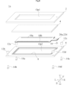
- FIG. 1 is an exploded perspective view of an electronic device 1 including a vibrating device 20.
- FIG. FIG. 2 is a cross-sectional view along AA in FIG.
- FIG. 3 is a top view of the vibration device 20.
- FIG. FIG. 4 is a perspective view of the vibration device 20.
- FIG. FIG. 5 is a perspective view of the vibration device 20.
- FIG. FIG. 6 is a cross-sectional view taken along line AA when the manipulation object 4 is pushed downward.
- FIG. 7 is a block diagram showing the hardware configuration of the vibration device 20.
- FIG. 8 is an exploded perspective view of the electronic device 1a including the vibration device 20a.
- FIG. 9 is a perspective view of the vibration device 20b.
- FIG. 10 is a plan view (partially transparent view) of the vibration device 20b and the operation target 4.
- FIG. FIG. 11 is a cross-sectional view taken along line BB shown in FIG.
- FIG. 1 is an exploded perspective view of an electronic device 1 including a vibrating device 20.
- FIG. 2 is a cross-sectional view along AA in FIG.
- FIG. 3 is a top view of the vibration device 20.
- FIG. 4 and 5 are perspective views of the vibration device 20.
- FIG. 1 is an exploded perspective view of an electronic device 1 including a vibrating device 20.
- FIG. 2 is a cross-sectional view along AA in FIG.
- FIG. 3 is a top view of the vibration device 20.
- FIG. 4 and 5 are perspective views of the vibration device 20.
- FIG. 1 is an exploded perspective view of an electronic device 1 including a vibrating device 20.
- FIG. 2 is a cross-sectional view along AA in FIG.
- FIG. 3 is a top view of the vibration device 20.
- FIG. 4 and 5 are perspective views of the vibration device 20.
- FIG. 1 is an exploded perspective view of an electronic device 1 including a vibrating device 20.
- FIG. 2 is
- the directions are defined as follows.
- the normal direction of the fixed portion 22 (see FIG. 3) having a flat plate shape is defined as the vertical direction.
- the vibrating device 20 has a rectangular shape when viewed in the vertical direction.
- the direction in which the long side of the vibrating device 20 extends is defined as the horizontal direction.
- the direction in which the short sides of the vibration device 20 extend is defined as the front-rear direction.
- the up-down direction, the left-right direction, and the front-rear direction are orthogonal to each other.
- the definition of the direction in this specification is an example. Therefore, the directions of the electronic device 1 and the vibrating device 20 during actual use do not need to match the directions in this specification.
- the vertical direction in FIG. 1 may be reversed.
- the horizontal direction may be reversed in FIG.
- the front-rear direction in FIG. 1 may be reversed.
- the electronic device 1 is, for example, a personal computer.
- FIG. 1 illustrates the vicinity of a touch pad type input device of a personal computer.
- the electronic device 1 includes an electronic device main body 2, an operation target 4, an electronic device main body 6, a cushion material 8, adhesive members 10a and 10b, spacers 12a to 12d, screws 14a to 14d, 16 and a sensor/drive circuit 50 (see FIG. 2).
- the operation target 4 is a member with which a part of the user's body comes into contact in order to operate the electronic device 1 .
- a user's body part is, for example, a finger.
- the operation target 4 is a touch pad type input device.
- the operation target 4 has a flat plate shape.
- the operation target 4 has a rectangular shape with long sides extending in the horizontal direction when viewed in the vertical direction.
- the shape of the operation target 4 is not limited to a rectangular shape. The user can operate the electronic device 1 by touching the operation target 4 or pushing the operation target 4 downward.
- the electronic device body 2 is the palm rest of the electronic device 1.
- a palm rest is a part that a user's palm touches when the user operates a keyboard or a touch pad type input device.
- the electronic device main body 2 is arranged on the operation target 4 .
- the electronic device main body 2 has a flat plate shape.
- the electronic device main body 2 is provided with a rectangular opening Op1 extending in the horizontal direction when viewed in the vertical direction.
- the opening Op1 overlaps the operation target 4 when viewed in the vertical direction.
- the length of the long side of the opening Op1 is slightly shorter than the length of the long side of the manipulation object 4 .
- the length of the short side of the opening Op1 is slightly shorter than the length of the short side of the manipulation object 4 . Therefore, part of the operation target 4 is exposed from the electronic device main body 2 through the opening Op1.
- the electronic device body 2 is made of, for example, SUS (Steel Use Stainless). However, the electronic device body 2 may be made of resin, for example.
- the electronic device main body 6 is a holder for the vibrating device 20, which will be described later. Therefore, the electronic device main body 6 supports the vibrating device 20 .
- the electronic device main body 6 is arranged below the operation target 4 .
- the electronic device main body 6 has a flat plate shape.
- the electronic device main body 6 has a rectangular shape with long sides extending in the horizontal direction when viewed in the vertical direction.
- the electronic device main body 6 is provided with a rectangular opening Op2 extending in the horizontal direction when viewed in the vertical direction.
- the opening Op2 overlaps the operation target 4 when viewed in the vertical direction.
- the length of the long side of the opening Op2 is slightly shorter than the length of the long side of the manipulation object 4 .
- the length of the short side of the opening Op2 is slightly shorter than the length of the short side of the manipulation object 4 . Therefore, the operation target 4 protrudes vertically and horizontally from the opening Op2 when viewed in the vertical direction. Thereby, the electronic device main body 6 surrounds at least a part of the operation target 4 when viewed in the vertical direction (the normal direction of the fixed portion 22).
- the electronic device body 6 is made of, for example, SUS (Steel Use Stainless).
- the cushion material 8 is provided on the upper main surface of the electronic device main body 6 . Therefore, the cushion material 8 is arranged under the operation target 4 .
- the cushion material 8 has a shape along the outer edge of the opening Op2 when viewed in the vertical direction. Therefore, the cushion material 8 has a rectangular frame shape when viewed in the vertical direction. However, the right side of the cushion material 8 is notched near the center. In addition, the cushion material 8 overlaps the outer edge of the operation target 4 when viewed in the vertical direction.
- the operation target 4 is placed on the electronic device main body 6 via a cushion material 8 .
- the cushion material 8 is, for example, an adhesive.
- the cushion material 8 is made of a material that easily deforms when the cushion material 8 receives an external force. As a result, the operation target 4 is fixed to the electronic device main body 6 in a state in which it is easily vibrated without being strongly restrained by the electronic device main body 6 .
- the spacers 12a to 12d are members for keeping the vertical distance between the electronic device body 2 and the electronic device body 6 constant.
- the spacers 12a to 12d have a columnar shape with central axes extending in the vertical direction.
- the spacer 12a is arranged at the left front corner of the electronic device main bodies 2 and 6 when viewed in the vertical direction.
- the spacer 12b is arranged at the left rear corner of the electronic device main body 2, 6 when viewed in the vertical direction.
- the spacer 12c is arranged at the right front corner of the electronic device main bodies 2 and 6 when viewed in the vertical direction.
- the spacer 12d is arranged at the right rear corner of the electronic device main bodies 2 and 6 when viewed in the vertical direction.
- the screws 14a fix the electronic device body 2, the electronic device body 6 and the spacer 12a.
- the screws 14b fix the electronic device body 2, the electronic device body 6 and the spacer 12b.
- the screw 14c fixes the electronic device main body 2, the electronic device main body 6 and the spacer 12c.
- the screws 14d fix the electronic device body 2, the electronic device body 6 and the spacer 12d.
- the vibration device 20 is used in the electronic device 1.
- the vibration device 20 vibrates the operation target 4 . Therefore, the vibration device 20 is arranged below the operation target 4 .
- the vibration device 20 is fixed to the operation target 4 .
- the vibrating device 20, as shown in FIGS. 3 to 5, includes a fixed portion 22, a vibrating portion 24, a piezoelectric film 26, and connecting portions 28a and 28b.
- the fixed part 22 is fixed to the electronic device main body 6 and has a flat plate shape. Accordingly, the fixed portion 22 has an upper major surface and a lower major surface.
- the fixed part 22 has a T shape.
- the fixing portion 22 includes a fixing portion body portion 222 and a fixing portion projecting portion 224 .
- the fixing portion main body portion 222 has a rectangular shape with long sides extending in the front-rear direction when viewed in the vertical direction.
- the fixing part projecting part 224 has a rectangular shape with long sides extending in the horizontal direction when viewed in the vertical direction.
- the left end of the fixing portion projecting portion 224 is connected to the center of the fixing portion main body portion 222 in the front-rear direction.
- the fixing part projecting part 224 is fixed to the electronic device main body 6 . Specifically, the fixing part projecting part 224 is fixed to the electronic device main body 6 by the screw 16 . Note that a double-sided tape may be used instead of the screw 16 for fixing the fixing portion projecting portion 224 .
- the vibrating portion 24 has a flat plate shape. Accordingly, the vibrating portion 24 has an upper major surface and a lower major surface.
- the vibrating portion 24 is arranged around the fixed portion 22 when viewed in the vertical direction (normal direction of the fixed portion 22). More specifically, the vibrating portion 24 partially surrounds the fixed portion 22 when viewed in the vertical direction (normal direction of the fixed portion 22).
- “the vibrating portion 24 surrounds a portion of the fixed portion 22 ” means that the vibrating portion 24 surrounds a portion of the fixed portion 22 .
- the vibrating portion 24 may have a frame shape, or may have a shape obtained by cutting out a part of the frame shape.
- the vibrating portion 24 has a shape in which a part of a rectangular frame shape is notched. A portion near the center of the right side of the vibrating portion 24 is notched. Below, the area surrounded by the vibrating portion 24 is defined as an enclosing area A1.
- the fixing portion main body portion 222 is arranged within the surrounding area A1 when viewed in the vertical direction (normal direction of the fixing portion 22).
- the fixing portion main body portion 222 is arranged at the right end portion of the surrounding area A1.
- the fixing portion main body portion 222 is not in contact with the vibrating portion 24 .
- the fixing part projecting part 224 protrudes from the surrounding area A1 when viewed in the vertical direction (normal direction of the fixing part 22).
- the fixing portion projecting portion 224 passes through a notch provided near the center of the right side of the vibrating portion 24 in the left-right direction. However, the fixing portion projecting portion 224 is not in contact with the vibrating portion 24 .
- the vibrating section 24 is fixed to the operation target 4 .
- the adhesive members 10 a and 10 b are provided on the upper main surface of the vibrating portion 24 .
- the bonding member 10a extends in the left-right direction along the front edge of the vibrating portion 24.
- the bonding member 10b extends in the left-right direction along the rear side of the vibrating portion 24.
- the adhesive members 10 a and 10 b are attached to the lower main surface of the operation target 4 . Thereby, the vibrating section 24 is fixed to the operation target 4 .
- the operation target 4 overlaps at least a portion of the vibrating portion 24 and at least a portion of the fixed portion body portion 222 when viewed in the vertical direction (normal direction of the fixed portion 22).
- the adhesive members 10a and 10b are, for example, double-sided tapes.
- the connecting portions 28 a and 28 b connect the vibrating portion 24 and the fixed portion 22 .
- the elastic deformation of the connecting portions 28a and 28b displaces the vibrating portion 24 with respect to the fixed portion 22 in the horizontal direction (perpendicular direction perpendicular to the normal direction of the fixed portion 22). More specifically, the connecting portions 28a and 28b are arranged within the surrounding area A1 when viewed in the vertical direction.
- the connecting portion 28a has a linear shape extending in the front-rear direction.
- the front end of the connecting portion 28 a is connected to the right end portion of the front side of the vibrating portion 24 .
- the rear end of the connecting portion 28 a is connected to the left end of the front side of the vibrating portion 24 .
- the connecting portion 28b has a linear shape extending in the front-rear direction.
- the rear end of the connecting portion 28b is connected to the right end of the rear side of the vibrating portion 24.
- the front end of the connecting portion 28 a is connected to the left end of the rear side of the vibrating portion 24 .
- the line width of the connecting portions 28a and 28b is narrow. Therefore, the connecting portions 28a and 28b can be easily elastically deformed. Thereby, the vibrating portion 24 can be displaced in the left-right direction with respect to the fixed portion 22 .
- the fixing portion 22, the vibrating portion 24, and the connecting portions 28a and 28b as described above are formed of a single metal plate.
- the metal plate may be coated with a resin such as polyimide.
- the metal plate is insulated.
- the fixed part 22, the vibrating part 24, and the connecting parts 28a and 28b are a single member, they are made of a material other than metal (for example, acrylic resin, PET, polycarbonate, glass epoxy, FRP, metal, glass, etc.). It may be a member manufactured by
- the piezoelectric film 26 is fixed to the vibrating portion 24 and the fixed portion 22 .
- Piezoelectric film 26 has an upper major surface and a lower major surface.
- the piezoelectric film 26 has a rectangular shape with long sides extending in the horizontal direction when viewed in the vertical direction.
- a piezoelectric film 26 is arranged below the fixed portion 22 and the vibrating portion 24 .
- the piezoelectric film 26 is fixed to the fixing portion body portion 222 .
- the right end portion of the upper main surface of the piezoelectric film 26 is fixed to the lower main surface of the fixing portion main body portion 222 with a double-sided tape 30a.
- the left end of the upper main surface of the piezoelectric film 26 is fixed to the lower main surface of the left side of the vibrating section 24 with a double-sided tape 30b.
- the piezoelectric film 26 vibrates with the fixing portion main body 222 so that the fixing portion main portion 222 is pulled leftward by the piezoelectric film 26 and the left side of the vibrating portion 24 is pulled rightward by the piezoelectric film 26 . It is stretched between it and the left side of the part 24 . Therefore, tension is generated in the piezoelectric film 26 so that the piezoelectric film 26 shrinks in the left-right direction.
- the piezoelectric film 26 is, for example, a film made of polyvinylidene fluoride (PVDF). However, the piezoelectric film 26 may be, for example, a film made of a chiral polymer.
- Chiral polymers include polylactic acid. Polylactic acid includes L-type polylactic acid (PLLA), D-type polylactic acid (PDLA), and the like.
- PVDF outputs a d31 component corresponding to expansion and contraction in the plane direction and a d33 component corresponding to expansion and contraction in the thickness direction.
- An electrode (not shown) is provided on each of the upper main surface of the piezoelectric film 26 and the lower main surface of the piezoelectric film 26 .
- One of the electrodes on both main surfaces of the piezoelectric film 26 has a reference potential (ground potential), and the other is a detection electrode.
- the sensor/drive circuit 50 is electrically connected to electrodes on both main surfaces of the piezoelectric film 26 .
- a sensor/drive circuit 50 detects the d31 component of the piezoelectric film 26 .
- FIG. 6 is a cross-sectional view along AA when the operation target 4 is pushed downward.
- the vibrating device 20 is fixed to the electronic device main body 6 with a fixing portion 22 .
- a vibrating section 24 of the vibrating device 20 is connected to the operation target 4 . Therefore, when the user performs an operation of pushing the operation target 4 downward, the fixed portion 22 of the vibrating device 20 does not move downward, and the vibrating portion 24 moves downward.
- the piezoelectric film 26 has a first end (left end on the upper main surface) connected to the fixed portion 22 and a second end connected to the vibrating portion 24 .
- the sensor/drive circuit 50 detects the voltage of the d31 component output according to the extension of the piezoelectric film 26 .
- the sensor/drive circuit 50 determines that the operation target 4 has been pressed, and applies voltage to the detection electrodes of the piezoelectric film 26 . That is, the detection electrodes of the piezoelectric film 26 also serve as voltage application electrodes.
- the piezoelectric film 26 expands and contracts in the horizontal direction according to the electrical signal.
- the piezoelectric film 26 vibrates the vibrating portion 24 in the left-right direction (perpendicular direction) with respect to the fixed portion 22 when an electric signal is applied thereto.
- Polylactic acid undergoes shear deformation according to the voltage of the electric signal.
- the film is cut so that the stretching direction of the piezoelectric film 26 is inclined by about 45° ⁇ 10° with respect to the horizontal direction. Thereby, the piezoelectric film 26 can expand and contract in the horizontal direction.
- FIG. 7 is a block diagram showing the configuration of the vibrating device 20.
- the sensor/drive circuit 50 has an MCU (Micro Controller Unit) 503 and a driver IC 504 .
- the MCU 503 and driver IC 504 are electrically connected to electrodes of the piezoelectric film 26 .
- a touch panel 501 is built in the operation target 4 .
- the touch panel 501 is, for example, a capacitive touch sensor.
- the touch panel IC 502 detects a change in capacitance that occurs in the touch panel 501 when the user touches the operation object 4, and detects touch operations, touch positions, and the like on the operation object 4.
- the MCU 503 detects the voltage output from the piezoelectric film 26.
- An amplifier circuit, an impedance conversion circuit, or the like can be appropriately inserted between the piezoelectric film 26 and the MCU 503 .
- the MCU 503 detects the voltage of the d31 component output according to the extension of the piezoelectric film 26 .
- the touch panel IC 502 detects the touch operation.
- the touch panel IC 502 detects a touch operation and the voltage value detected by the piezoelectric film 26 exceeds a predetermined threshold value, the MCU 503 determines that the operation target 4 has been pressed.
- the MCU 503 determines that the operation target 4 is not pressed. If the touch panel IC 502 does not detect a touch operation even when the voltage value detected by the piezoelectric film 26 exceeds a predetermined threshold value, the MCU 503 determines that the operation object 4 has not been pressed. As a result, the MCU 503 does not erroneously recognize an operation other than the pressing operation, such as when the operation object 4 is hit by an obstacle.
- the MCU 503 determines that a pressing operation has been performed, it instructs the driver IC 504 to output an electrical signal.
- the driver IC 504 applies voltage to the electrodes of the piezoelectric film 26 .
- the vibration device 20 can transmit vibrations to the user more efficiently. For example, since a vibrator using PZT (lead zirconate titanate) vibrates in the vertical direction, the vibration is inhibited by the user's finger pressing force. Moreover, PZT has a problem of being cracked by a strong external force. However, in the vibration device 20 of the present embodiment, the direction in which the user presses the operation target 4 is the vertical direction, and the vibration direction is the horizontal direction, which are different directions. Therefore, the vibration is not hindered by the pressing force of the finger. Moreover, unlike PZT, the piezoelectric film does not crack due to an external force.
- PZT lead zirconate titanate
- the fixed part 22 is fixed to the electronic device main body 6 .
- the vibrating section 24 is fixed to the operation target 4 .
- the piezoelectric film 26 vibrates the vibrating portion 24 in the horizontal direction with respect to the fixed portion 22 .
- the vibration of the vibrating section 24 is directly transmitted to the operation target 4 with which a part of the user's body is in contact.
- the vibration device 20 can more efficiently transmit vibrations to the user.
- the vibration device 20 can transmit vibrations to the user more efficiently. More specifically, the vibrating section 24 is arranged around the fixed section 22 when viewed in the vertical direction. Therefore, the fixed portion 22 does not exist around the vibrating portion 24 . As a result, the design of the outer peripheral portion of the vibrating portion 24 is less likely to be restricted by the fixed portion 22 . That is, the degree of freedom in designing the vibrating portion 24 is increased. As a result, it becomes easy to design the vibrating portion 24 to have a structure that allows the vibrating portion 24 to easily vibrate. Therefore, according to the vibration device 20, vibration can be transmitted to the user more efficiently.
- the fixed portion 22, the vibrating portion 24, and the connecting portions 28a and 28b are made of one metal plate. Accordingly, the fixed portion 22, the vibrating portion 24, and the connecting portions 28a and 28b can be formed by punching one metal plate. As a result, the fixed portion 22, the vibrating portion 24, and the connecting portions 28a and 28b can be easily formed.
- the size of the electronic device 1 can be reduced. More specifically, the electronic device main body 6 surrounds at least a portion of the operation target 4 when viewed in the vertical direction. The operation target 4 overlaps at least a portion of the vibrating portion 24 and at least a portion of the fixed portion main body portion 222 when viewed in the vertical direction. As a result, most of the vibration device 20 overlaps the operation target 4 when viewed in the vertical direction. As a result, the size of the electronic device 1 can be reduced.
- the vibrating device 20 of this embodiment can detect a pressing operation and give tactile feedback to the pressing operation without providing a separate pressure sensor.
- the electrode for pressure detection and the electrode for voltage application are not separated. Therefore, the piezoelectric film 26 can increase the electrode area. Therefore, the vibrating device 20 of the present embodiment can both increase the sensitivity to the pressing operation and increase the amplitude.
- the structure of the vibrating device 20 may be any structure as long as the piezoelectric film 26 expands and contracts according to the pressing operation on the operation target 4 .
- FIG. 8 is an exploded perspective view of the electronic device 1a including the vibration device 20a.
- the electronic device 1a differs from the electronic device 1 in the structure of the operation target 4 and in that the vibrating device 20a is fixed to the electronic device main body 2.
- the electronic device 1a will be described below with a focus on these differences.
- the operation target 4 has a structure in which a glass plate, a touchpad type input device, and a liquid crystal panel are stacked in this order from top to bottom.
- the operation target 4 is a touch pad type input device having a display function.
- the vibration device 20a is fixed to the electronic device main body 2. More specifically, the fixing part projecting part 224 is fixed to the electronic device main body 2 .
- the fixing part projecting part 224 is fixed to the electronic device main body 2 by the screw 16 . Note that a double-sided tape may be used instead of the screw 16 for fixing the fixing portion projecting portion 224 .
- the rest of the structure of the electronic device 1a is the same as that of the electronic device 1, so the description is omitted.
- the fixing part projecting part 224 projects from the surrounding area A1 when viewed in the vertical direction. As a result, the operation target 4 and the vibrating section 24 no longer exist above or below a part of the fixing section protruding section 224 . As a result, the fixing part projecting part 224 can be fixed to the electronic device main body 6 like the electronic device 1, or can be fixed to the electronic device main body 2 like the electronic device 1a.
- the vibration device 20a can also detect the pressing operation and provide tactile feedback for the pressing operation without providing a separate pressure sensor.
- the fixed portion 22, the vibrating portion 24 and the connecting portions 28a and 28b do not have to be formed by one member. That is, the fixed portion 22 and the vibrating portion 24 may be connected by connecting portions 28a and 28b, which are elastic bodies such as springs and rubber.
- the fixing portion 22 does not have to include the fixing portion projecting portion 224 .
- the fixing portion main body 222 is fixed to the electronic device main body 2 or the electronic device main body 6 .
- the opening Op2 is not an essential component in the vibrating devices 20 and 20a.
- the thickness of the cushion material 8 may be larger than the thickness of the vibrating device 20 .
- the vibrating device 20 does not come into contact with the electronic device main body 6 and the vibration is not hindered.
- the opening Op2 does not exist, the thickness of the electronic device 1, 1a is increased, but the influence of heat, noise, etc. from the outside of the electronic device 1, 1a on the piezoelectric film 26 is reduced.
- a depression may be provided instead of the opening Op2.
- the vibrating devices 20, 20a provided with recesses can also achieve the same effects as the vibrating devices 20, 20a provided with the openings Op2.
- the thickness of the vibrating device 20, 20a is also reduced in the vibrating device 20, 20a provided with the recess.
- the entire portion (rectangular portion) of the vibrating device 20 excluding the fixing portion 22 overlaps the opening Op2 when viewed in the vertical direction.
- the vibrating device 20 is prevented from contacting the electronic device main body 6 and impeding the vibration of the vibrating section 24 .
- the vibrating portion 24 may not have a shape in which a part of the rectangular frame shape is notched.
- the vibrating portion 24 may be arranged around the fixed portion 22 when viewed in the vertical direction.
- the vibrating portion 24 may have, for example, a structure that has a front side and a rear side and no left side and no right side. That is, the vibrating portion 24 may be two rectangular members extending in the left-right direction.
- the structure of the vibration device may be the structure according to Modification 2 as follows.
- FIG. 9 is a perspective view of the vibration device 20b.
- FIG. 10 is a plan view (partially transparent view) of the vibration device 20b and the operation target 4.
- FIG. 11 is a cross-sectional view taken along line BB shown in FIG.
- the vibrating device 20b is different from the vibrating device 20 and the vibrating device 20a in that the fixed portion 22 surrounds a portion of the vibrating portion 24 in plan view.
- the fixed part 22 is fixed to the electronic device main body.
- the vibrating portion 24 includes a vibrating main body portion 24A arranged in an enclosing region surrounded by the fixing portion 22 in plan view, and a vibrating body portion 24A protruding from the enclosing region surrounded by the fixing portion 22 in plan view.
- a projecting portion 24B is provided.
- the vibration projecting portion 24B is connected to the operation target 4.
- the piezoelectric film 26 is connected to the downward principal surface of the vibration body portion 24A and the downward principal surface of the fixing portion 22 .
- the vibrating projecting portion 24B moves downward, and the vibrating main body portion 24A also moves downward.
- the vibration body portion 24A moves downward, the tension of the piezoelectric film 26 is relaxed and the piezoelectric film 26 shrinks in the plane direction. Therefore, even with such a structure, when the operation object 4 is pushed, the sensor/drive circuit 50 detects the voltage of the d31 component output according to the shrinkage of the piezoelectric film 26 . Therefore, the vibration device 20b can also detect the pressing operation and provide tactile feedback for the pressing operation without providing a separate pressure sensor.
- the vibrating device 20 b also includes a plate-like vibrating portion 24 , a piezoelectric film 26 connected to the vibrating portion 24 , a fixed portion 22 connected to the piezoelectric film 26 , and the vibrating portion 24 and the fixed portion 22 . It is provided with connecting portions 28a and 28b that are connected and can be displaced by elastic deformation in the plane direction.
- the piezoelectric film 26 bridges the vibrating portion 24 and the fixed portion 22 in a tensioned state. expands and contracts by pressing the operation object 4 .
- the vibrating device 20b detects an electric signal generated in the piezoelectric film 26 by the pressing operation, applies an electric signal to the piezoelectric film 26, and vibrates the piezoelectric film 26 in the planar direction (sensor/driving circuit). 50).
- the fixing part 22 is a frame-shaped member in Modification 2, it does not have to be frame-shaped.
- the fixing part 22 is connected to the piezoelectric film and the vibrating part, and may have any shape as long as it can fix the piezoelectric film and the vibrating part.
- the shape of the vibrating portion is not limited to the shape shown in the second modification.
- the vibrating portion may have any shape as long as it is connected to the piezoelectric film and vibrates in accordance with the vibration of the piezoelectric film.
Landscapes
- Engineering & Computer Science (AREA)
- General Engineering & Computer Science (AREA)
- Theoretical Computer Science (AREA)
- Mechanical Engineering (AREA)
- Human Computer Interaction (AREA)
- Physics & Mathematics (AREA)
- General Physics & Mathematics (AREA)
- User Interface Of Digital Computer (AREA)
- Apparatuses For Generation Of Mechanical Vibrations (AREA)
Priority Applications (2)
| Application Number | Priority Date | Filing Date | Title |
|---|---|---|---|
| JP2023542288A JP7416341B2 (ja) | 2021-08-19 | 2022-07-25 | 振動装置 |
| CN202290000610.XU CN221827305U (zh) | 2021-08-19 | 2022-07-25 | 振动装置 |
Applications Claiming Priority (2)
| Application Number | Priority Date | Filing Date | Title |
|---|---|---|---|
| JP2021-133900 | 2021-08-19 | ||
| JP2021133900 | 2021-08-19 |
Publications (1)
| Publication Number | Publication Date |
|---|---|
| WO2023021937A1 true WO2023021937A1 (ja) | 2023-02-23 |
Family
ID=85240515
Family Applications (1)
| Application Number | Title | Priority Date | Filing Date |
|---|---|---|---|
| PCT/JP2022/028581 Ceased WO2023021937A1 (ja) | 2021-08-19 | 2022-07-25 | 振動装置 |
Country Status (3)
| Country | Link |
|---|---|
| JP (1) | JP7416341B2 (https=) |
| CN (1) | CN221827305U (https=) |
| WO (1) | WO2023021937A1 (https=) |
Citations (3)
| Publication number | Priority date | Publication date | Assignee | Title |
|---|---|---|---|---|
| JP2012174235A (ja) * | 2011-02-24 | 2012-09-10 | Kyocera Corp | 電子機器 |
| WO2019013164A1 (ja) * | 2017-07-14 | 2019-01-17 | 株式会社村田製作所 | 振動構造、振動装置、および触覚提示装置 |
| JP2019160200A (ja) * | 2018-03-16 | 2019-09-19 | 株式会社デンソーテン | 操作入力装置および操作入力装置の駆動方法 |
-
2022
- 2022-07-25 CN CN202290000610.XU patent/CN221827305U/zh active Active
- 2022-07-25 JP JP2023542288A patent/JP7416341B2/ja active Active
- 2022-07-25 WO PCT/JP2022/028581 patent/WO2023021937A1/ja not_active Ceased
Patent Citations (3)
| Publication number | Priority date | Publication date | Assignee | Title |
|---|---|---|---|---|
| JP2012174235A (ja) * | 2011-02-24 | 2012-09-10 | Kyocera Corp | 電子機器 |
| WO2019013164A1 (ja) * | 2017-07-14 | 2019-01-17 | 株式会社村田製作所 | 振動構造、振動装置、および触覚提示装置 |
| JP2019160200A (ja) * | 2018-03-16 | 2019-09-19 | 株式会社デンソーテン | 操作入力装置および操作入力装置の駆動方法 |
Also Published As
| Publication number | Publication date |
|---|---|
| JP7416341B2 (ja) | 2024-01-17 |
| JPWO2023021937A1 (https=) | 2023-02-23 |
| CN221827305U (zh) | 2024-10-11 |
Similar Documents
| Publication | Publication Date | Title |
|---|---|---|
| US11455038B2 (en) | Vibration structure, vibration device, and tactile sense presentation device | |
| JP7143941B2 (ja) | 振動装置 | |
| US11009953B2 (en) | Tactile sense presenting device | |
| JP6128281B2 (ja) | 振動装置および触覚提示装置 | |
| WO2016035628A1 (ja) | 振動装置 | |
| WO2016067831A1 (ja) | 振動装置 | |
| US20230001451A1 (en) | Vibration structure, vibration device, and tactile sense presentation device | |
| US12504822B2 (en) | Vibration device | |
| JP5975185B2 (ja) | 触覚提示装置 | |
| CN115023300B (zh) | 振动装置以及电子设备 | |
| JP7416341B2 (ja) | 振動装置 | |
| JP6311464B2 (ja) | 触覚提示装置 | |
| JP2017068795A (ja) | 触覚提示装置 | |
| JP7586132B2 (ja) | 触覚提示装置 | |
| CN213601183U (zh) | 振动构造 | |
| WO2018105639A1 (ja) | 触覚提示装置 | |
| WO2024116708A1 (ja) | 触感提示装置 | |
| JP2016045605A (ja) | 触覚提示装置 | |
| JP2016053889A (ja) | 触覚提示装置 |
Legal Events
| Date | Code | Title | Description |
|---|---|---|---|
| 121 | Ep: the epo has been informed by wipo that ep was designated in this application |
Ref document number: 22858259 Country of ref document: EP Kind code of ref document: A1 |
|
| WWE | Wipo information: entry into national phase |
Ref document number: 2023542288 Country of ref document: JP |
|
| WWE | Wipo information: entry into national phase |
Ref document number: 202290000610.X Country of ref document: CN |
|
| NENP | Non-entry into the national phase |
Ref country code: DE |
|
| 122 | Ep: pct application non-entry in european phase |
Ref document number: 22858259 Country of ref document: EP Kind code of ref document: A1 |