WO2023021809A1 - 圧縮機 - Google Patents
圧縮機 Download PDFInfo
- Publication number
- WO2023021809A1 WO2023021809A1 PCT/JP2022/022314 JP2022022314W WO2023021809A1 WO 2023021809 A1 WO2023021809 A1 WO 2023021809A1 JP 2022022314 W JP2022022314 W JP 2022022314W WO 2023021809 A1 WO2023021809 A1 WO 2023021809A1
- Authority
- WO
- WIPO (PCT)
- Prior art keywords
- piston
- opening
- chamber
- cylinder
- compressor
- Prior art date
- Legal status (The legal status is an assumption and is not a legal conclusion. Google has not performed a legal analysis and makes no representation as to the accuracy of the status listed.)
- Ceased
Links
Images

Classifications
-
- F—MECHANICAL ENGINEERING; LIGHTING; HEATING; WEAPONS; BLASTING
- F04—POSITIVE - DISPLACEMENT MACHINES FOR LIQUIDS; PUMPS FOR LIQUIDS OR ELASTIC FLUIDS
- F04B—POSITIVE-DISPLACEMENT MACHINES FOR LIQUIDS; PUMPS
- F04B39/00—Component parts, details, or accessories, of pumps or pumping systems specially adapted for elastic fluids, not otherwise provided for in, or of interest apart from, groups F04B25/00 - F04B37/00
- F04B39/10—Adaptations or arrangements of distribution members
-
- F—MECHANICAL ENGINEERING; LIGHTING; HEATING; WEAPONS; BLASTING
- F04—POSITIVE - DISPLACEMENT MACHINES FOR LIQUIDS; PUMPS FOR LIQUIDS OR ELASTIC FLUIDS
- F04B—POSITIVE-DISPLACEMENT MACHINES FOR LIQUIDS; PUMPS
- F04B39/00—Component parts, details, or accessories, of pumps or pumping systems specially adapted for elastic fluids, not otherwise provided for in, or of interest apart from, groups F04B25/00 - F04B37/00
- F04B39/0005—Component parts, details, or accessories, of pumps or pumping systems specially adapted for elastic fluids, not otherwise provided for in, or of interest apart from, groups F04B25/00 - F04B37/00 adaptations of pistons
- F04B39/0016—Component parts, details, or accessories, of pumps or pumping systems specially adapted for elastic fluids, not otherwise provided for in, or of interest apart from, groups F04B25/00 - F04B37/00 adaptations of pistons with valve arranged in the piston
Definitions
- the present disclosure relates to a compressor that generates compressed air, for example.
- Patent Literatures 1 and 2 describe compressors in which air is sucked into the compression chamber from the crank chamber side through a communication passage formed in the piston.
- the piston is provided with a plate-like valve (suction valve) for opening and closing the opening of the communication passage.
- An object of one embodiment of the present invention is to provide a compressor that can achieve both "increasing the opening of the communication passage of the piston” and “increasing the lift amount of the intake valve”.
- a cylinder is partitioned into a first chamber and a second chamber, and a reciprocating piston; and a communication passage formed in the piston and communicating the first chamber and the second chamber.
- an opening provided on one side surface of the piston on the side of the first chamber at one end of the communication passage; and a suction valve for opening and closing the opening, wherein the suction valve is plate-shaped.
- a fixing portion fixed to the center of the one side surface, a closing portion on one side in the radial direction of the fixing portion, and a spring portion on the other side in the radial direction of the fixing portion, and the spring on the one side surface
- the spring portion facing portion facing the portion is a compressor that is recessed more than the closing portion facing portion facing the closing portion.
- both “increasing the opening of the communication passage of the piston” and “increasing the lift amount of the intake valve” can be achieved.
- FIG. 4 is an exploded perspective view showing a piston, an intake valve, and the like; It is a top view which shows a suction valve. It is a perspective view which shows the state which attached the suction valve to the piston.
- FIG. 11 is an explanatory diagram exaggeratingly showing a state in which the spring portion of the suction valve is elastically deformed (a state in which the closing portion is separated from the opening of the communicating passage of the piston);
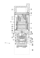
- the compressor according to the embodiment is configured as a linear motor type compressor will be described below with reference to the accompanying drawings.
- the linear motor compressor is attached to the vehicle body as part of the air suspension system of a four-wheeled vehicle.
- a linear motor type compressor 1 is configured as an air compressor.
- the compressor 1 can be used, for example, as a compressor that draws in and compresses atmospheric air (normal compressor) and/or as a compressor that draws in air (compressed air) compressed from a tank or the like and further compresses it (booster compressor). can be done.
- the compressor 1 includes a linear motor 2 as a drive source and a compression section 16 having a cylinder 17 and a piston 18 .
- the linear motor 2 reciprocates the mover 5 in the length direction (horizontal direction in FIG. 1) by applying current to the coil (not shown) of the armature 4, thereby moving the piston 18 of the compression portion 16. Reciprocate in the same direction.
- the linear motor 2 is attached to, for example, a vehicle (automobile) body (not shown) together with the compression unit 16 .
- the linear motor 2 includes a casing 3 forming an outer shell, and an armature 4 , a mover 5 , a support member 6 and a spring 7 arranged inside the casing 3 .
- a casing 3 of the linear motor 2 is formed as a hollow container.
- the casing 3 includes a cylindrical case main body 3A having openings on both sides in the axial direction, and a cylinder-side partition wall closing the cylinder 17 side (for example, the left side in FIG. 1) which is one side in the axial direction.
- an inverter-side partition wall portion 3C that closes the inverter 15 side (for example, the right side in FIG. 1) that is the other side in the axial direction.
- An armature 4 , a mover 5 , a support member 6 and a spring 7 are housed inside the casing 3 .
- the armature 4 and the mover 5 generate magnetic attraction and repulsion between them when the armature 4 is energized.
- the spring 7 is composed of, for example, a compression coil spring, and always biases the mover 5 toward one side (cylinder 17 side) in the longitudinal direction of the casing 3 .
- the spring 7 is elastically flexurally deformed so as to expand and contract when the mover 5 reciprocates.
- a casing 3 of the linear motor 2 accommodates a motor including an armature 4 and a mover 5 inside. Of these, the mover 5 protrudes from the casing 3 into the cylinder 17 of the compression section 16 .
- the mover 5 has an output shaft 8 that reciprocates by being driven by the linear motor 2 .
- a piston 18 is provided on the projecting end side of the output shaft 8 .
- the output shaft 8 corresponds to the piston rod.
- the piston 18 side of the output shaft 8 is a piston support portion 10 that supports the piston 18 . That is, the piston 18 side of the output shaft 8 is composed of a rod portion 9 extending in the axial direction and a piston support portion 10 connected to the rod portion 9 . A rod portion 9 of the output shaft 8 is supported by the cylinder-side partition wall portion 3B via a slide bearing 11 so as to be axially displaceable.
- the piston support portion 10 is attached to the tip of the rod portion 9 . That is, the piston support portion 10 is provided on the tip side of the rod portion 9 (on the side of the piston 18). In this case, the piston support portion 10 is formed in a disk shape with an outer diameter smaller than that of the lip ring 20 that constitutes the piston 18 .
- the piston support portion 10 includes a cylindrical central portion 10A, a ring portion 10B positioned on the outer diameter side of the central portion 10A, and positioned between the central portion 10A and the ring portion 10B.
- a plurality of (for example, three) connecting portions 10C for connecting both are provided.
- An air passage 12 connected to the communication passage 19A of the piston 18 is formed between the connection portions 10C adjacent in the circumferential direction.
- the piston support portion 10 is provided with the air passage 12 that communicates the communication passage 19A of the piston 18 and the suction chamber 22 of the compression portion 16 .
- a female screw 10D with which the mounting screw 13 is screwed is provided in the central portion 10A of the piston support portion 10.
- a piston 18 that is, a piston body 19 and a lip ring 20
- an intake valve 23 are attached to the piston support portion 10 with attachment screws 13 .
- a cylindrical inverter case 14 with a bottom is provided on the other side of the casing 3 in the length direction, that is, on the side opposite to the compression section 16.
- An inverter 15 that controls driving of the linear motor 2 is provided in the inverter case 14 .
- the inverter 15 includes, for example, a power transistor or the like that generates a high voltage for energizing the armature 4 .
- the compression section 16 of the linear motor type compressor 1 is provided in a state of being sandwiched between the linear motor 2 and the air dryer 28, for example.
- the compression section 16 includes a cylinder 17 , a piston 18 , an intake valve 23 , a discharge valve 24 and a cylinder head 25 .
- the compressor 16 compresses air (or already compressed air) in the cylinder 17 by reciprocating the piston 18 in the axial direction together with the mover 5 of the linear motor 2 to compress the compressed air (or further compressed air) is generated.
- the cylinder 17 is formed in a cylindrical shape with a bottom, for example, using a metal material such as aluminum.
- the cylinder 17 includes a cylindrical tubular portion 17A and a bottom portion 17B that closes one end side (for example, the left side in FIG. 1) of the tubular portion 17A. 17 C of discharge holes which penetrate the bottom part 17B are provided in the bottom part 17B.
- the cylinder 17 is attached to the cylinder-side partition wall portion 3B of the casing 3 . That is, the cylinder-side partition wall portion 3B is provided with a mounting tubular portion 3D for fitting the tubular portion 17A of the cylinder 17 so as to protrude toward the cylinder 17 side.
- the cylinder 17 is attached to the casing 3 by being sandwiched between the cylinder-side partition wall portion 3B and the cylinder head 25 while being fitted to the attachment tube portion 3D of the cylinder-side partition wall portion 3B.
- a piston 18 is housed inside the cylinder 17 so as to be able to reciprocate (slid).
- the piston 18 is connected to the mover 5 of the linear motor 2 .
- the piston 18 is provided in the cylinder 17 so as to be slidable in the longitudinal direction of the linear motor 2 (casing 3) (that is, in the axial direction of the cylinder 17, which is the horizontal direction in FIG. 1). That is, the piston 18 reciprocates within the cylinder 17 in conjunction with the reciprocating motion of the mover 5 .
- the piston 18 is arranged on the same axis as the mover 5 of the linear motor 2 moves.
- the piston 18 is inserted into the cylinder 17 so as to be able to reciprocate.
- the piston 18 partitions the inside of the cylinder 17 into a compression chamber 21 and a suction chamber 22 .
- the piston 18 is provided with a communication passage 19A that communicates the suction chamber 22 and the compression chamber 21, and a suction valve 23 that opens and closes the communication passage 19A.
- the piston 18 includes a piston body 19 provided with a communicating passage 19A, and a lip ring 20 provided on the outer peripheral side of the piston body 19.
- an insertion hole 19E through which the mounting screw 13 is inserted is provided.
- Lip ring 20 seals between piston 18 and cylinder 17 .
- the lip ring 20 is formed as a seal member having an L-shaped cross section made of, for example, a wear-resistant and self-lubricating resin material.
- the compression chamber 21 is formed as a columnar space surrounded by the cylindrical portion 17A and bottom portion 17B of the cylinder 17 and the piston 18 .
- the suction chamber 22, also called the suction chamber, is formed as a cylindrical space surrounded by the cylindrical portion 17A of the cylinder 17, the cylinder-side partition wall portion 3B of the casing 3, the piston 18, and the rod portion 9 of the output shaft 8.
- External air or compressed air flows into the suction chamber 22 through a suction port 3E provided in the cylinder-side partition wall portion 3B of the casing 3 .
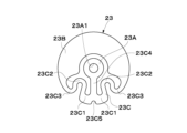
- the suction valve 23 includes a fixed portion 23A fixed to the piston 18, a closing portion 23B that covers an opening 19A1 of the communication passage 19A of the piston 18 so that it can be opened and closed, and an opening 19A1 of the communication passage 19A that is elastically deformed to close the closing portion 23B. and a spring portion 23C tilted in a direction away from the .
- the suction valve 23 opens the communication passage 19A of the piston 18 during the suction stroke of the compression portion 16 (piston 18) to allow communication between the suction chamber 22 and the compression chamber 21 in the cylinder 17. In the compression stroke of the compression portion 16 (piston 18 ), the suction valve 23 closes (closes) the communication passage 19 ⁇ /b>A of the piston 18 to block communication between the compression chamber 21 and the suction chamber 22 in the cylinder 17 .
- the discharge valve 24 is provided between the bottom portion 17B of the cylinder 17 and the cylinder head 25.
- the discharge valve 24 covers one end of the cylinder 17 (more specifically, a discharge hole 17C in the bottom portion 17B of the cylinder 17) so as to be able to open and close.
- the discharge valve 24 includes, for example, a base portion 24A sandwiched between the bottom portion 17B of the cylinder 17 and the cylinder head 25, a notch 24B having an annular shape, and opening and closing the discharge hole 17C located inside the notch 24B. It is configured by a closing portion 24C that can be covered.
- the discharge valve 24 (blocking portion 24C) closes the discharge hole 17C during the suction stroke of the compression portion 16 to block the communication between the compression chamber 21 in the cylinder 17 and the discharge chamber 26 in the cylinder head 25.
- the discharge valve 24 (closed portion 24C) opens the discharge hole 17C during the compression stroke of the compression portion 16 to allow the compression chamber 21 in the cylinder 17 and the discharge chamber 26 in the cylinder head 25 to communicate with each other.
- the cylinder head 25 is attached to one end side of the cylinder 17 (for example, the left end side in FIG. 1) so as to cover the bottom portion 17B of the cylinder 17.
- the cylinder head 25 is formed in a bottomed cylindrical shape.
- a discharge chamber 26 is formed between the cylinder head 25 and the bottom portion 17B of the cylinder 17 .
- the cylinder head 25 is provided on the side of the air dryer 28 as a discharge portion for discharging compressed air.
- a plurality of fixtures 27 are provided between the cylinder head 25 and the casing 3 (cylinder-side partition wall 3B) of the linear motor 2 to connect and fix the two.
- the fixture 27 is arranged radially outside the cylinder 17 with a gap in the circumferential direction between the cylinder head 25 and the casing 3 (cylinder-side partition wall 3B) of the linear motor 2 .
- the fixture 27 clamps the cylinder 17 between the cylinder head 25 and the casing 3 (cylinder-side partition wall 3B) of the linear motor 2 .
- the cylinder head 25 is provided with a discharge port 25A that communicates with the air dryer 28 .
- the discharge port 25 ⁇ /b>A communicates between the discharge chamber 26 and the air dryer 28 .
- the air dryer 28 is attached to one end side of the cylinder head 25 (for example, the left end side in FIG. 1). That is, the air dryer 28 is provided on the side opposite to the linear motor 2 with the compression section 16 interposed therebetween.
- the inside of the air dryer 28 is filled with a desiccant.
- the air dryer 28 dries the air by bringing the desiccant into contact with the compressed air discharged from the compression section 16 to absorb moisture in the compressed air with the desiccant.
- a suction valve intake valve
- a single plate-shaped suction valve separates the “portion that closes the opening (blocking portion)” and the “portion that determines the stroke (spring portion)”.
- the central portion of the intake valve 23 is fixed to the piston 18 as a fixing portion 23A.
- one side in the radial direction of the central portion (fixed portion 23A) is formed as a blocking portion 23B that openably and closably covers the opening 19A1 of the communicating passage 19A, and the area of the opening 19A1 that is blocked by this blocking portion 23B is ensured. do.
- the other side in the radial direction with respect to the central portion (fixed portion 23A) is referred to as a spring portion 23C.
- a relief step is provided on the seat surface of the spring portion 23C (the spring portion facing portion 19B of the piston 18).
- the spring portion 23C is provided with bent portions 23C1, 23C2, and 23C3 to reduce the spring constant.
- the opening 19A1 of the communication passage 19A of the piston 18 can be increased, and the lift amount of the suction valve 23 (the amount by which the blocking portion 23B moves away from the opening 19A1) can be increased.
- the compressor 1 of this embodiment has a piston 18, a communication passage 19A, an opening 19A1, and a suction valve 23.
- the piston 18 divides the inside of the cylinder 17 into a compression chamber 21 as a first chamber and a suction chamber 22 as a second chamber.
- the piston 18 reciprocates within the cylinder 17 .
- Communicating passage 19A is formed in piston 18 . More specifically, the communication path 19A is provided in a piston body 19 that constitutes the piston 18 as a through hole that axially penetrates the piston body 19 .
- the communication passage 19A communicates with the suction chamber 22 via the air passage 12 of the piston support portion 10. As shown in FIG. Thereby, the communication passage 19A communicates the compression chamber 21 and the suction chamber 22 with each other.
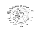
- the opening 19A1 is one end of the communication path 19A and is provided on one side surface of the piston 18 on the compression chamber 21 side (for example, the left side surface in FIG. 1 and the upper side surface in FIG. 2).
- the opening 19A1 is formed in an arcuate shape extending from the first end E1 to the second end E2 along the outer diameter (peripheral edge) of one side surface of the piston 18.
- the angle of the opening 19A1 formed by the first end E1, the second end E2, and the center O of one side surface is greater than 180 degrees. That is, the opening 19A1 is located on the outer diameter side of the circular piston 18 (piston body 19) and formed in an arc shape extending over 180 degrees in the circumferential direction.
- the suction valve 23 opens and closes the opening 19A1 of the communication passage 19A of the piston 18 (piston body 19).
- the suction valve 23 is plate-shaped. More specifically, the suction valve 23 has a substantially disk shape.
- the suction valve 23 has a fixing portion 23A, a closing portion 23B, and a spring portion 23C.
- the fixing portion 23A is fixed to the center of one side surface of the piston 18 (the surface on the side of the compression chamber 21). For this reason, the fixing portion 23A is provided with a mounting hole 23A1 through which the mounting screw 13 is inserted.
- the closing part 23B is arranged on one side in the radial direction of the fixing part 23A (for example, the right side in the left-right direction in FIGS. 2 and 4 and the upper side in the up-down direction in FIG. 3).
- the closing portion 23B is arranged at a position corresponding to the opening 19A1 of the communication passage 19A of the piston 18 (piston body 19).
- the closing portion 23B is a portion that covers the opening 19A1 of the piston 18 so as to be able to be opened and closed, and like the opening 19A1 of the piston 18, extends over 180 degrees in the circumferential direction.
- the spring portion 23C is disposed on the other side in the radial direction of the fixing portion 23A (for example, the left side in the left-right direction in FIGS. 2 and 4 and the lower side in the up-down direction in FIG. 3).
- the spring portion 23C is provided on the opposite side of the closing portion 23B in the radial direction across the fixing portion 23A.
- the spring portion 23C has at least two bent portions, more specifically, three bent portions 23C1, 23C2, and 23C3.
- the spring portion 23C includes a straight portion 23C4 extending radially outward from the fixed portion 23A, and a U-shape extending radially inward from one end of the straight portion 23C4 (the outer diameter side of the intake valve 23).
- the first bent portions 23C1, 23C1 that are bent at 180°, and the second bent portions that are bent at about 180° in a U shape radially outward from the other end side of the first bent portions 23C1, 23C1 (the inner diameter side of the intake valve 23).
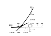
- Such a spring part 23C tilts the closing part 23B in a direction away from the opening 19A1 of the piston 18 by elastically deforming as shown in FIG. Note that FIG. 5 exaggerates the state in which the spring portion 23C of the intake valve 23 is elastically deformed (that is, the state in which the closing portion 23B is separated from the opening 19A1 of the piston 18 (piston body 19)).
- a positioning concave portion 23C5 is provided at a position corresponding to the spring portion 23C (more specifically, a position corresponding to one end side of the linear portion 23C4) on the outer peripheral edge of the suction valve 23.
- the positioning recess 23C5 is formed in a notch shape that is recessed radially inward from the outer peripheral edge of the intake valve 23 .
- the positioning concave portion 23C5 engages with a rotation restricting portion 19D provided on the piston 18 (piston body 19).
- one side surface of the piston 18 (piston body 19 ), that is, the surface on the side of the compression chamber 21 (the surface on the side of the intake valve 23 ) serves as the seating surface of the intake valve 23 .
- the seat surface has a spring portion facing portion 19B facing the spring portion 23C of the suction valve 23 and a closing portion facing portion 19C facing the closing portion 23B of the suction valve 23.
- a communicating passage 19A of the piston 18 (piston main body 19) opens to a blocking portion facing portion 19C.
- a spring portion facing portion 19B of one side surface of the piston 18 (piston body 19) is recessed more than a closing portion facing portion 19C.
- the spring portion facing portion 19B is a recessed step surface (flank surface) with respect to the closing portion facing portion 19C. Therefore, as shown in FIG. 5, when the spring portion 23C is elastically deformed, the suction valve 23 enters the side of the spring portion facing portion 19B located lower than the closing portion facing portion 19C, thereby closing the closing portion 23B. can be inclined in a direction greatly away from the opening 19A1 of the piston 18.
- a rotation restricting portion 19D that restricts the rotation of the suction valve 23 is formed in the spring portion facing portion 19B.
- the rotation restricting portion 19D is provided at a position corresponding to the positioning concave portion 23C5 of the suction valve 23 on the outer diameter side of the spring portion facing portion 19B.
- the rotation restricting portion 19D restricts the rotation of the intake valve 23 by engaging with the positioning recess 23C5 of the intake valve 23.
- the suction valve 23 can be positioned in the rotational direction with respect to the piston 18 (piston body 19) by engaging the positioning recess 23C5 of the suction valve 23 and the rotation restricting portion 19D of the piston 18 (piston body 19).
- the cylinder 17 is divided into the compression chamber 21 as the first chamber and the suction chamber 22 as the second chamber, and the cylinder 17 reciprocates within the cylinder 17 .
- a moving piston 18 is provided.
- the piston 18 is provided with a communication passage 19A that communicates the compression chamber 21 and the suction chamber 22 with each other.
- a suction valve 23 is fixed to the piston 18 to open and close the communication passage 19A.
- the compression chamber 21 has a discharge valve 24, and the compression chamber 21 communicates with a discharge port 25A via the discharge valve 24.
- the intake chamber 22 opens into an intake 3E, also called intake.
- the suction valve 23 has a fixing portion 23A, which is the central portion, fixed to one side surface (seat surface) of the piston 18 (piston body 19) by means of the mounting screw 13.
- a communication passage 19A leading to a suction chamber 22 below the piston 18 is open on one radial side of one side surface of the piston 18 (piston body 19).
- a spring facing portion 19B is provided as a relief step so as not to hinder the operation (elastic deformation).
- the spring portion facing portion 19B is recessed in a direction away from the intake valve 23 relative to the closing portion facing portion 19C.
- a rotation restricting portion 19D that restricts the rotation of the suction valve 23 is provided on the spring portion facing portion 19B so as to protrude from the spring portion facing portion 19B.
- the suction valve 23 includes a central fixing portion 23A, a closing portion 23B provided on one radial side of the fixing portion 23A to close an opening 19A1 of the communicating passage 19A, and a radial direction of the fixing portion 23A. It has a fixing portion 23A provided on the side and a spring portion 23C connected to the closing portion 23B.
- the spring portion 23C is provided with bent portions 23C1, 23C2, and 23C3.
- the linear motor type compressor 1 has the configuration as described above, and its operation will be described next.
- the mover 5 receives thrust in the axial direction.
- a magnetic attraction force and a repulsion force are generated between the armature 4 and the mover 5.
- the mover 5 repeats reciprocating motion in the length direction (axial direction) within the casing 3 between the pair of armatures 4 .
- the thrust accompanying the reciprocating motion of the mover 5 is transmitted to the piston 18 inside the cylinder 17 that constitutes the compression section 16 .
- the piston 18 repeats reciprocating motion in the axial direction within the cylinder 17 to perform the compression operation. That is, in the intake stroke in which the piston 18 moves toward the intake chamber 22, the pressure in the compression chamber 21 decreases and the intake valve 23 opens. As a result, air (or compressed air) is sucked from the suction port 3E, and the air (or compressed air) on the side of the suction chamber 22 passes through the air passage 12 of the piston support portion 10 and the communication passage 19A of the piston 18 to the side of the compression chamber 21. flow.
- the intake valve 23 is closed.
- the discharge valve 24 is opened, and the compressed air is discharged through the discharge chamber 26 to the discharge port 25A.
- the compressed air discharged from the discharge port 25A is dried by an air dryer 28, for example, and then supplied to the air chamber of the air suspension of the vehicle.
- the suction valve 23 opens, as shown in FIG. 5, the bent portion 23C3 of the spring portion 23C is elastically deformed toward the seat surface.
- a spring portion facing portion 19B serving as a relief step is provided so as to be recessed from the closed portion facing portion 19C. Therefore, the operation (elastic deformation) of the spring portion 23C is not hindered, and the lift amount of the intake valve 23 can be increased.
- the length of the spring portion 23C (that is, from the fixed portion 23A to the closed portion 23B) is connection length) can be lengthened, and the spring constant can be lowered. As a result, the passage area of the communication passage 19A can be secured, and the suction resistance can be reduced.
- the piston 18 includes the spring portion facing portion 19B facing the spring portion 23C of the suction valve 23 and the closing portion facing portion 19C facing the closing portion 23B of the suction valve 23. ing.
- the spring portion facing portion 19B is recessed more than the closing portion facing portion 19C. Therefore, when the spring portion 23C of the suction valve 23 is elastically deformed and the closing portion 23B moves away from the opening 19A1 of the communication passage 19A, the spring portion 23C enters the spring portion facing portion 19B recessed from the closing portion facing portion 19C. (goes down). This makes it easier for the blocking portion 23B to tilt away from the opening 19A1.
- the opening 19A1 of the communication passage 19A of the piston 18 is enlarged, the amount (lift amount) of the closing portion 23B of the intake valve 23 separated from the opening 19A1 can be increased.
- both “enlarging the opening 19A1 of the communication passage 19A of the piston 18" and “enlarging the lift amount of the intake valve 23” can be achieved. Therefore, even if the diameter of the piston 18 of the compressor 1 is reduced, the opening 19A1 of the communication passage 19A of the piston 18 can be increased and the lift amount of the intake valve 23 can be increased, so that the load at high pressure can be reduced. In addition, air volume and pressure can be secured.
- the opening 19A1 of the communication passage 19A of the piston 18 extends along the outer diameter (peripheral edge) of the piston 18 over 180 degrees. Therefore, the opening 19A1 of the communication passage 19A can be enlarged, and the efficiency of the compressor 1 can be improved.
- the spring portion 23C of the suction valve 23 has at least two, more specifically three bending portions 23C1, 23C2, and 23C3. Therefore, the length of the spring portion 23C (connection length from the fixed portion 23A to the closed portion 23B) can be ensured, and the spring constant can be reduced. As a result, the lift amount can be increased and the discharge air amount can be ensured.
- the spring portion facing portion 19B of the piston 18 is formed with a rotation restricting portion 19D that restricts the rotation of the intake valve 23 . Therefore, when the suction valve 23 is attached to the piston 18, the suction valve 23 can be positioned by the rotation restricting portion 19D. As a result, the work of attaching the intake valve 23 to the piston 18 can be facilitated.
- the spring portion 23C of the intake valve 23 has three bent portions 23C1, 23C2, and 23C3 has been described as an example.
- the present invention is not limited to this, and the bending portion of the spring portion may be one, two, or four or more.
- the opening 19A1 of the communication path 19A has been described as an arc-shaped opening extending over 180 degrees in the circumferential direction.
- the opening of the communication path may be an arc-shaped opening within 180 degrees.
- the shape of the opening is not limited to an arc shape, and may be a shape other than an arc shape, such as a fan shape, a polygonal shape, or a linear shape.
- a configuration including a plurality of communication paths or a plurality of openings may be employed.
- the piston 18 of the compression portion 16 is an oscillating piston directly connected to the output shaft 8 (rod portion 9) serving as a piston rod
- the piston is not limited to this and may be a normal piston connected to the piston rod via a piston pin.
- the linear motor type compressor 1 in which the compression unit 16 is driven by the linear motor 2 has been described as an example.
- the configuration is not limited to this, and a configuration in which the compression portion (piston) is driven (reciprocated) using a drive source other than a linear motor, for example, may be adopted. That is, the compressor should just be a compressor in which a piston reciprocates.
- the compressor may be used as a compressor (ordinary compressor) that sucks and compresses atmospheric air, or may be used as a compressor (booster compressor) that sucks air (compressed air) compressed from a tank or the like and further compresses it. may Further, the compressor may compress gases other than air.
- the compressor 1 may be applied to a closed-type air suspension system in which compressed air can be stored in a tank.
- the present invention may be applied to an open-type air suspension system that does not use a tank for storing compressed air (that is, a system that exhausts compressed air to the outside).
- the compressor 1 is mounted on a vehicle.
- it is not limited to this, and can be mounted on various machines that require a compressor, for example. That is, the compressor may be mounted on various machines other than vehicles. Alternatively, the compressor may be used alone.
- the case where the central axis of the linear motor 2, the central axis of the compression section 16, and the central axis of the air dryer 28 are arranged so as to coincide with each other has been described as an example.
- the present invention is not limited to this, and does not exclude, for example, the case where the central axis of the compression section and the central axis of the air dryer are arranged at positions offset with respect to the central axis of the linear motor.
- the central axis of the linear motor and the central axis of the air dryer may be offset from the central axis of the compression section, or the central axis of the linear motor and the central axis of the compression section may be offset from the central axis of the air dryer. It may be offset.
- the piston includes the spring portion facing portion facing the spring portion of the suction valve and the closing portion facing portion facing the closing portion of the suction valve.
- the spring portion facing portion is recessed more than the closing portion facing portion. Therefore, when the spring portion of the suction valve is elastically deformed and the closing portion moves away from the opening of the communication passage, the spring portion enters (lowers) into the spring portion facing portion recessed from the closing portion facing portion, thereby can be easily tilted away from the opening. As a result, even if the opening of the communication passage of the piston is increased, the amount (lift amount) by which the closed portion of the intake valve separates from the opening can be increased.
- the opening of the communication passage of the piston extends over 180 degrees along the outer diameter (peripheral edge) of the piston. Therefore, the opening of the communication passage can be enlarged, and the efficiency of the compressor can be improved.
- the spring portion of the suction valve has at least two bends. Therefore, the length of the spring portion can be secured, and the spring constant can be lowered. As a result, the lift amount can be increased and the discharge air amount can be ensured.
- the rotation restricting portion that restricts the rotation of the intake valve is formed in the portion of the piston that faces the spring portion. Therefore, when the suction valve is attached to the piston, the suction valve can be positioned by the rotation restricting portion. As a result, the work of attaching the intake valve to the piston can be facilitated.
Landscapes
- Engineering & Computer Science (AREA)
- Mechanical Engineering (AREA)
- General Engineering & Computer Science (AREA)
- Compressor (AREA)
- Compressors, Vaccum Pumps And Other Relevant Systems (AREA)
Abstract
Description
Claims (4)
- シリンダ内を第1室と第2室に区画し、往復動するピストンと、
前記ピストンに形成され、前記第1室と前記第2室とを連通する連通路と、
前記連通路の一端であって、前記ピストンの前記第1室側の一側面に設けられる開口と、
前記開口を開閉する吸込弁と、を有し、
前記吸込弁は、板状であって、
前記一側面の中央に固定される固定部と、
前記固定部の径方向一側の閉塞部と、
前記固定部の径方向他側のバネ部と、を有し、
前記一側面の前記バネ部と対向するバネ部対向部は、前記閉塞部と対向する閉塞部対向部よりも凹んでいる圧縮機。 - 前記開口は、前記一側面の外径に沿って第1端から第2端まで延びる円弧状に形成され、
前記第1端、前記第2端と前記一側面の中心とで形成される角度は、180度より大きい請求項1に記載の圧縮機。 - 前記バネ部は、少なくとも2か所の屈曲部を有する請求項1に記載の圧縮機。
- 前記一側面の前記バネ部対向部には、前記吸込弁の回転を規制する回転規制部が形成される請求項1に記載の圧縮機。
Priority Applications (4)
| Application Number | Priority Date | Filing Date | Title |
|---|---|---|---|
| CN202280049175.4A CN117616201A (zh) | 2021-08-19 | 2022-06-01 | 压缩机 |
| JP2023542229A JP7629999B2 (ja) | 2021-08-19 | 2022-06-01 | 圧縮機 |
| US18/292,600 US12584472B2 (en) | 2021-08-19 | 2022-06-01 | Compressor |
| DE112022004014.9T DE112022004014T5 (de) | 2021-08-19 | 2022-06-01 | Kompressor |
Applications Claiming Priority (2)
| Application Number | Priority Date | Filing Date | Title |
|---|---|---|---|
| JP2021133756 | 2021-08-19 | ||
| JP2021-133756 | 2021-08-19 |
Publications (1)
| Publication Number | Publication Date |
|---|---|
| WO2023021809A1 true WO2023021809A1 (ja) | 2023-02-23 |
Family
ID=85240429
Family Applications (1)
| Application Number | Title | Priority Date | Filing Date |
|---|---|---|---|
| PCT/JP2022/022314 Ceased WO2023021809A1 (ja) | 2021-08-19 | 2022-06-01 | 圧縮機 |
Country Status (5)
| Country | Link |
|---|---|
| US (1) | US12584472B2 (ja) |
| JP (1) | JP7629999B2 (ja) |
| CN (1) | CN117616201A (ja) |
| DE (1) | DE112022004014T5 (ja) |
| WO (1) | WO2023021809A1 (ja) |
Families Citing this family (1)
| Publication number | Priority date | Publication date | Assignee | Title |
|---|---|---|---|---|
| WO2026095195A1 (ko) * | 2024-10-30 | 2026-05-07 | 엘지전자 주식회사 | 리니어 압축기 |
Citations (5)
| Publication number | Priority date | Publication date | Assignee | Title |
|---|---|---|---|---|
| JPS5514172U (ja) * | 1978-07-12 | 1980-01-29 | ||
| JPH0521185U (ja) * | 1991-09-03 | 1993-03-19 | 株式会社ハドシス | ポンプ用ピストンへの吸入弁取付構造 |
| JP2002054571A (ja) * | 2000-08-16 | 2002-02-20 | Keihin Corp | 往復動式圧縮機 |
| KR20040025462A (ko) * | 2002-09-19 | 2004-03-24 | 엘지전자 주식회사 | 압축기용 밸브 |
| JP2004525310A (ja) * | 2001-05-25 | 2004-08-19 | エルジー エレクトロニクス インコーポレイティド | 往復動式圧縮機の吸入バルブ |
Family Cites Families (6)
| Publication number | Priority date | Publication date | Assignee | Title |
|---|---|---|---|---|
| JPS5924884B2 (ja) | 1978-07-19 | 1984-06-13 | 新日本製鐵株式会社 | ブリキ原板の調質圧延法 |
| JPH0521185A (ja) | 1991-06-27 | 1993-01-29 | Matsushita Electric Works Ltd | インバータ装置 |
| JPH07208368A (ja) | 1994-01-20 | 1995-08-08 | Tokico Ltd | ピストン揺動式圧縮機 |
| KR20040022787A (ko) * | 2002-09-07 | 2004-03-18 | 엘지전자 주식회사 | 왕복동식 압축기의 가스 흡입장치 |
| KR100531827B1 (ko) * | 2003-12-17 | 2005-12-02 | 엘지전자 주식회사 | 왕복동식 압축기의 흡입밸브 조립체 |
| JP2017106397A (ja) | 2015-12-11 | 2017-06-15 | 株式会社日立産機システム | 圧縮機 |
-
2022
- 2022-06-01 US US18/292,600 patent/US12584472B2/en active Active
- 2022-06-01 DE DE112022004014.9T patent/DE112022004014T5/de active Pending
- 2022-06-01 CN CN202280049175.4A patent/CN117616201A/zh active Pending
- 2022-06-01 WO PCT/JP2022/022314 patent/WO2023021809A1/ja not_active Ceased
- 2022-06-01 JP JP2023542229A patent/JP7629999B2/ja active Active
Patent Citations (5)
| Publication number | Priority date | Publication date | Assignee | Title |
|---|---|---|---|---|
| JPS5514172U (ja) * | 1978-07-12 | 1980-01-29 | ||
| JPH0521185U (ja) * | 1991-09-03 | 1993-03-19 | 株式会社ハドシス | ポンプ用ピストンへの吸入弁取付構造 |
| JP2002054571A (ja) * | 2000-08-16 | 2002-02-20 | Keihin Corp | 往復動式圧縮機 |
| JP2004525310A (ja) * | 2001-05-25 | 2004-08-19 | エルジー エレクトロニクス インコーポレイティド | 往復動式圧縮機の吸入バルブ |
| KR20040025462A (ko) * | 2002-09-19 | 2004-03-24 | 엘지전자 주식회사 | 압축기용 밸브 |
Also Published As
| Publication number | Publication date |
|---|---|
| JP7629999B2 (ja) | 2025-02-14 |
| US12584472B2 (en) | 2026-03-24 |
| DE112022004014T5 (de) | 2024-05-29 |
| JPWO2023021809A1 (ja) | 2023-02-23 |
| CN117616201A (zh) | 2024-02-27 |
| US20250314243A1 (en) | 2025-10-09 |
Similar Documents
| Publication | Publication Date | Title |
|---|---|---|
| CN101384459B (zh) | 电机泵组 | |
| KR100480086B1 (ko) | 리니어 압축기의 흡입손실 저감구조 | |
| US6485271B1 (en) | Body supporting apparatus for hermetic compressor | |
| CN112005011A (zh) | 具有排出消音器的封闭式压缩机 | |
| JP2009522497A (ja) | ハイブリッド摂動ポンプ | |
| JP7629999B2 (ja) | 圧縮機 | |
| KR101855014B1 (ko) | 왕복동식 압축기 | |
| US11761683B2 (en) | Linear compressor | |
| WO2023037672A1 (ja) | 圧縮機 | |
| US8062004B2 (en) | Discharging noise system of a hermetic compressor | |
| WO2019234881A1 (ja) | 密閉型圧縮機、及び、密閉型圧縮機の製造方法 | |
| US20210108628A1 (en) | Linear compressor | |
| US11092361B2 (en) | Linear compressor | |
| KR20210028979A (ko) | 실린더 및 이를 포함하는 왕복동식 압축기 | |
| CN115839326B (zh) | 压缩机 | |
| KR101379610B1 (ko) | 가변용량형 사판식 압축기 | |
| KR20230084815A (ko) | 왕복동식 압축기 | |
| KR101814239B1 (ko) | 왕복동식 압축기 | |
| JPH11303732A (ja) | リニア圧縮機 | |
| JP7449100B2 (ja) | ダイヤフラムポンプ | |
| KR100963936B1 (ko) | 사판식 압축기 | |
| JP2002098045A (ja) | ポンプ | |
| JPH0791367A (ja) | 真空ポンプ装置 | |
| KR20220106560A (ko) | 왕복동식 압축기 | |
| KR101866731B1 (ko) | 가변 용량형 사판식 압축기 |
Legal Events
| Date | Code | Title | Description |
|---|---|---|---|
| 121 | Ep: the epo has been informed by wipo that ep was designated in this application |
Ref document number: 22858133 Country of ref document: EP Kind code of ref document: A1 |
|
| WWE | Wipo information: entry into national phase |
Ref document number: 2023542229 Country of ref document: JP |
|
| WWE | Wipo information: entry into national phase |
Ref document number: 202280049175.4 Country of ref document: CN |
|
| 122 | Ep: pct application non-entry in european phase |
Ref document number: 22858133 Country of ref document: EP Kind code of ref document: A1 |
|
| WWP | Wipo information: published in national office |
Ref document number: 18292600 Country of ref document: US |