WO2023021783A1 - 歯科用ハンドピース - Google Patents
歯科用ハンドピース Download PDFInfo
- Publication number
- WO2023021783A1 WO2023021783A1 PCT/JP2022/016275 JP2022016275W WO2023021783A1 WO 2023021783 A1 WO2023021783 A1 WO 2023021783A1 JP 2022016275 W JP2022016275 W JP 2022016275W WO 2023021783 A1 WO2023021783 A1 WO 2023021783A1
- Authority
- WO
- WIPO (PCT)
- Prior art keywords
- cam
- dental handpiece
- vibrating
- vibrating cylinder
- axial direction
- Prior art date
- Legal status (The legal status is an assumption and is not a legal conclusion. Google has not performed a legal analysis and makes no representation as to the accuracy of the status listed.)
- Ceased
Links
Images



Classifications
-
- A—HUMAN NECESSITIES
- A61—MEDICAL OR VETERINARY SCIENCE; HYGIENE
- A61C—DENTISTRY; APPARATUS OR METHODS FOR ORAL OR DENTAL HYGIENE
- A61C1/00—Dental machines for boring or cutting ; General features of dental machines or apparatus, e.g. hand-piece design
- A61C1/08—Machine parts specially adapted for dentistry
- A61C1/12—Angle hand-pieces
-
- A—HUMAN NECESSITIES
- A61—MEDICAL OR VETERINARY SCIENCE; HYGIENE
- A61C—DENTISTRY; APPARATUS OR METHODS FOR ORAL OR DENTAL HYGIENE
- A61C1/00—Dental machines for boring or cutting ; General features of dental machines or apparatus, e.g. hand-piece design
- A61C1/02—Dental machines for boring or cutting ; General features of dental machines or apparatus, e.g. hand-piece design characterised by the drive of the dental tools
- A61C1/07—Dental machines for boring or cutting ; General features of dental machines or apparatus, e.g. hand-piece design characterised by the drive of the dental tools with vibratory drive, e.g. ultrasonic waves
-
- A—HUMAN NECESSITIES
- A61—MEDICAL OR VETERINARY SCIENCE; HYGIENE
- A61C—DENTISTRY; APPARATUS OR METHODS FOR ORAL OR DENTAL HYGIENE
- A61C1/00—Dental machines for boring or cutting ; General features of dental machines or apparatus, e.g. hand-piece design
- A61C1/08—Machine parts specially adapted for dentistry
- A61C1/18—Flexible shafts; Clutches or the like; Bearings or lubricating arrangements; Drives or transmissions
- A61C1/185—Drives or transmissions
-
- A—HUMAN NECESSITIES
- A61—MEDICAL OR VETERINARY SCIENCE; HYGIENE
- A61C—DENTISTRY; APPARATUS OR METHODS FOR ORAL OR DENTAL HYGIENE
- A61C5/00—Filling or capping teeth
- A61C5/40—Implements for surgical treatment of the roots or nerves of the teeth; Nerve needles; Methods or instruments for medication of the roots
-
- A—HUMAN NECESSITIES
- A61—MEDICAL OR VETERINARY SCIENCE; HYGIENE
- A61C—DENTISTRY; APPARATUS OR METHODS FOR ORAL OR DENTAL HYGIENE
- A61C3/00—Dental tools or instruments
- A61C3/02—Tooth drilling or cutting instruments; Instruments acting like a sandblast machine
- A61C3/03—Instruments operated by vibration
Definitions
- the present invention relates to a dental handpiece for driving a dental piece such as a file and/or reamer attached to the tip to treat the root canal of a tooth.
- a dental piece for root canal treatment such as scraping the wall of the root of a patient's decayed tooth, removing a pus block and/or filling material stuck at the tip of the root, and/or removing the nerve.
- files and/or reamers are used.
- gutta-percha root canal filling material
- an object of the present invention is to provide a wall dental handpiece that can improve the efficiency of cutting the root canal of a tooth using a dental piece such as a reamer.
- the dental handpiece of the present invention is a first tubular member; a second tubular member having a side wall formed with a communication hole communicating with the internal space of the first tubular member and connected to one end of the first tubular member at the side wall; A dental piece having a needle base and a needle extending from the needle base supports the needle base in a state in which the needle is projected into an external space, and is coaxially inserted through the second cylindrical member.
- a vibrating cylinder with a rotary member arranged in the internal space of the first tubular member such that one end faces the internal space of the second tubular member through the communication hole; an actuator that rotates the rotating member about a central axis.
- one end of the rotating member is provided with a cam protrusion projecting at a position eccentric to the central axis of the rotating member,
- a cam recess into which the cam protrusion is fitted is formed on the outside of the side wall of the vibrating cylinder,
- the cam concave portion is formed so that the cam convex portion of the rotary member can be relatively displaced in the circumferential direction of the vibrating cylinder.
- the cam recess forms an annular cam groove that extends along the entire circumference of the outer side wall of the vibrating cylinder, or a cam groove that extends continuously along a portion of the outer side wall of the vibrating cylinder in the circumferential direction. It is preferable that
- the cam recess is formed outside the side wall of the vibrating cylinder so that the width of the cam recess in the axial direction of the vibrating cylinder varies in the circumferential direction of the vibrating cylinder.
- At least one side surface of a pair of side surfaces of the cam recess that face each other in the axial direction of the vibrating cylinder is formed as a wavy surface.
- At least one side surface of a pair of side surfaces of the cam recess that face each other in the axial direction of the vibrating cylinder is formed as a gear surface having a plurality of teeth
- At least part of the side surface of the cam projection is preferably formed as a gear surface having a plurality of teeth meshing with the gear surface.
- a plurality of mounting holes, into which the cam protrusions are mounted are formed at one end of the rotating member at locations with different eccentricities with respect to the central axis of the rotating member.
- a sliding layer is preferably formed on at least one of the surfaces of the cam protrusion and the cam recess.
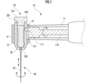
- FIG. 1 is a configuration explanatory diagram of a dental handpiece as a first embodiment of the present invention
- FIG. 2 is an explanatory diagram of the configuration of the essential parts of the dental handpiece of FIG. 1
- FIG. 6 is an explanatory diagram of the configuration of a main part of a dental handpiece as a second embodiment of the present invention
- FIG. 10 is an explanatory diagram of the configuration of a main part of a dental handpiece as a third embodiment of the present invention
- FIG. 11 is an explanatory diagram of the configuration of a main part of a dental handpiece as a fourth embodiment of the present invention
- FIG. 4 is an explanatory view of the configuration of a main part of a dental handpiece as another embodiment of the present invention
- a dental handpiece 10 as a first embodiment of the present invention schematically shown in FIG. 1 is configured to drive a reamer 40 (or file) as a dental piece.
- the dental handpiece 10 includes a first tubular member 11 , a second tubular member 12 (supporting tube), and a vibrating tube 20 .
- the first tubular member 11 is formed in a substantially cylindrical shape.
- the second cylindrical member 12 is formed in a substantially cylindrical shape, and the central axis of the second cylindrical member 12 is included in the central axis of the first cylindrical member 11 at a certain angle (for example, within an angle range of 90° to 120°).
- a vibrating cylinder 20 is connected to the distal end portion of the first cylindrical member 11 at its side wall in such a posture as to form or cross the first cylindrical member 11 .
- the vibrating cylinder 20 is positioned substantially coaxially with the second cylindrical member 12 and in a direction parallel to the central axis of the second cylindrical member 12 (FIGS. 1 and 2). vertical direction) is inserted so as to be able to vibrate.
- the first cylindrical member 11, the second cylindrical member 12 and the vibration cylinder 20 are made of metal such as aluminum alloy and stainless steel.
- the first tubular member 11 and the second tubular member 12 are integrally made of the same metal.
- the vibrating cylinder 20 may be made of the same metal as the first tubular member 11 and the second tubular member 12, or may be made of a different metal.
- a substantially cylindrical rotating member 110 is arranged with its center axis parallel or substantially parallel to the longitudinal direction of the first cylindrical member 11 . It is placed in an extended position.
- the tip of the rotating member 110 is formed in a substantially cylindrical shape with a relatively large diameter.
- the distal end portion is provided with a cam pin 111 (cam convex portion) that protrudes in a direction parallel to the central axis of the rotating member 110 eccentrically.
- a pin mounting hole extending parallel to the central axis may be formed in the distal end portion of the rotating member 110, and the cam pin 111 may be detachably mounted in the pin mounting hole.
- the rotating member 110 is configured to be connected to the rotating shaft of the electric motor of the chair unit and driven to rotate about the central axis.
- a switch for ON/OFF-controlling the operation of the electric motor is, for example, a foot switch (not shown).
- the inner space of the first tubular member 11 and the inner space of the second tubular member 12 communicate with each other through a communication hole 121 formed in the side wall of the second tubular member 12. ing.
- a cam hole 21 (cam concave portion) that is locally recessed in the radial direction is formed on the outer side wall of the vibrating cylinder 20 .
- a cam pin 111 of a rotating member 110 is fitted into the cam hole 21 of the vibrating cylinder 20 .
- the cam hole 21 is a substantially cylindrical cam pin so that there is play between the cam pin 111 and the cam hole 21 in the circumferential and axial directions of the vibrating cylinder 20. It is formed in a substantially circular shape with a diameter larger than that of 111 .
- the respective shapes of the cam pin 111 and the cam hole 21 may be designed in various forms.
- the cam hole 21 may be formed in a substantially elliptical shape in which each of the short diameter and the long diameter is larger than the diameter of the substantially cylindrical cam pin 111 .
- the major axis direction of the elliptical cam hole 21 may be parallel to the axial direction of the vibrating cylinder 20, or may be designed to form a certain angle such as 30° or 90°.
- the cam hole 21 may be formed in a substantially circular shape with a larger diameter than the major axis of the substantially elliptical cylindrical cam pin 111 .
- the major axis direction of the elliptical cam pin 111 may be parallel to the axial direction of the vibrating cylinder 20, or may be designed to form a certain angle such as 30° or 90°.
- a sliding layer for improving slidability (reducing friction force) is formed on at least the outer surface of the cam pin 111 of the rotating member 110 and at least the side surface (or side surface and bottom surface) of the cam hole 21 of the vibration cylinder 20.
- the sliding layer may be composed of a carbon coating layer such as DLC (Diamond-Like Carbon).
- the inner space of the vibrating barrel 20 communicates with the external space through a mounting opening 201 on one end side, and communicates with the external space through a through hole 202 having a smaller diameter than the mounting opening 201 on the other end side. are doing.
- One end of the internal space of the vibration cylinder 20 is closed by attaching the cover member 24 to the mounting opening 201 .
- the lid member 24 is composed of a substantially disk-shaped head portion 241 and a substantially cylindrical mounting portion 242 protruding from one end of the head portion 241 .
- a female thread is formed on the inner side wall of the mounting opening 201 of the vibrating cylinder 20
- a male thread is formed on the side surface of the mounting portion 242 of the cover member 24 to be screwed into the female thread.
- the female thread of the vibrating cylinder 20 and/or the male thread of the lid member 24 may be omitted, and the mounting portion 242 of the lid member 24 may be fitted to the vibrating cylinder 20 by being pressed against the inner side wall of the vibrating cylinder 20 .
- the lid member 24 is made of metal such as aluminum alloy or stainless steel.
- the reamer 40 has a needle base 41 and a needle portion 42 .
- the needle part 42 is fixed to the needle base body 41 so as to protrude in the axial direction from one end side of the substantially cylindrical needle base body 41 .
- the needle portion 42 is formed so as to gradually decrease in diameter from the proximal portion to the distal portion.
- the reamer 40 is attached to the vibrating barrel 20 with the needle base 41 housed in the inner space of the vibrating barrel 20 and the needle portion 42 partially protruding from the through hole 202 .
- One end of the needle base 41 abuts on the stepped portion of the through hole 202 and the other end abuts on the end of the mounting portion 242 of the cover member 24 .
- fixed for Needle 42 may be flexible or bendable.
- the second cylindrical member 12, the vibrating cylinder 20 and the lid member 24 constitute a support mechanism that supports the reamer 40 (dental piece) so as to vibrate.
- the cam pin 111 and the cam hole 21 are designed such that the size of the cam hole 21 is larger than the size of the cam pin 111 in each of the axial direction and the circumferential direction of the vibrating cylinder 20 (see FIG. 2). Therefore, the rotary member 110 is rotationally driven, and a vibration force acts on the vibrating cylinder 20 in its axial direction through the cam pin 111, whereby the vibrating cylinder 20 vibrates or oscillates in the axial direction with respect to the second cylindrical member 12. It reciprocates and vibrates or reciprocates in the circumferential direction.
- the practitioner applies the vibrating needle part 42 to the wall of the root canal of the patient's tooth to perform root canal treatment, etc. can be implemented.
- the cam pin 111 and the cam hole 21 are designed so that the amplitude of the reamer 40 in the axial direction of the second tubular member 12 is any value within the range of 0.4 mm to 2.0 mm. This makes it easier to feed the needle part 42 to the root apex of the root canal.
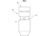
- a substantially annular cam groove 211 extending along the entire circumference is formed.
- a cam pin 111 of the rotating member 110 is fitted in the cam groove 211 of the vibrating cylinder 20 .
- the cam groove 211 extends in the circumferential direction over a portion (for example, 0° to 350°) of the azimuth angle range of 0° to 360° with respect to the central axis of the vibrating cylinder 20, and intermittently at one point. It may be formed on the outside of the side wall of the vibrating cylinder 20 in an annular shape.
- the dental handpiece 10 as the second embodiment of the present invention has the same configuration as the dental handpiece 10 (see FIGS. 1 and 2) as the first embodiment of the present invention except for the above configuration. Common reference numerals are used for common configurations, and description thereof is omitted.
- the cam pin 111 and the cam groove 211 are designed such that the size of the cam groove 211 is larger than the size of the cam pin 111 in each of the axial direction and the circumferential direction of the vibrating cylinder 20 (see FIG. 3). Therefore, the rotary member 110 is rotationally driven, and a vibration force acts on the vibrating cylinder 20 in its axial direction through the cam pin 111, whereby the vibrating cylinder 20 vibrates or oscillates in the axial direction with respect to the second cylindrical member 12. It reciprocates and vibrates or reciprocates in the circumferential direction.
- the needle portion 42 protruding from the through hole 202 of the vibration cylinder 20 vibrates while bending, the operator applies the vibrating needle portion 42 to the root canal of the patient's tooth to perform root canal treatment or the like. be able to.
- a substantially annular cam groove 211 is formed extending over the area.
- a cam pin 111 of the rotating member 110 is fitted in the cam groove 211 of the vibrating cylinder 20 .
- At least one side surface (lower side surface in FIG. 4) of a pair of side surfaces defining the cam groove 211 in the axial direction of the vibrating cylinder 20 is formed as a wavy surface 2110 .
- the amplitude and period of the wavy surface 2110 are designed so that the cam pin 111 can relatively displace along the cam groove 211 in the circumferential direction of the vibrating cylinder 20 .
- a dental handpiece 10 as a third embodiment of the present invention has the same configuration as the dental handpiece 10 (see FIGS. 1 and 2) as the first embodiment of the present invention except for the above configuration. Common reference numerals are used for common configurations, and description thereof is omitted.
- the cam pin 111 and the cam hole 21 or the cam groove 211 are designed such that the size of the cam hole 21 or the cam groove 211 is larger than the size of the cam pin 111 in each of the axial direction and the circumferential direction of the vibrating cylinder 20 . Therefore, the rotary member 110 is rotationally driven, and a vibration force acts on the vibrating cylinder 20 in its axial direction through the cam pin 111, whereby the vibrating cylinder 20 vibrates or oscillates in the axial direction with respect to the second cylindrical member 12. It reciprocates and vibrates or reciprocates in the circumferential direction.
- the needle portion 42 protruding from the through hole 202 of the vibration cylinder 20 vibrates while bending, the operator applies the vibrating needle portion 42 to the root canal of the patient's tooth to perform root canal treatment or the like. be able to.
- the amplitude of the needle portion 42 of the reamer 40 in the axial direction becomes irregular. can give sexuality.
- the needle portion 42 of the reamer 40 can scrape the wall of the root canal of the tooth with some latitude, and the wall can be scraped efficiently.
- a substantially annular cam groove 211 is formed extending over the area.
- a cam pin 111 of the rotating member 110 is fitted in the cam groove 211 of the vibrating cylinder 20 .
- At least one of the pair of side surfaces defining the cam groove 211 in the axial direction of the vibrating cylinder 20 (lower side surface in FIG. 4) is formed as a gear surface 2112 .
- a part of the side wall of the cam pin 111 is formed as a gear surface 1112 that meshes with the gear surface 2112 .
- the gear surface 2112 and the tooth height and tooth pitch of the gear surface 1112 are designed so that the cam pin 111 can relatively displace along the cam groove 211 in the circumferential direction of the vibrating cylinder 20 .
- a dental handpiece 10 as a third embodiment of the present invention has the same configuration as the dental handpiece 10 (see FIGS. 1 and 2) as the first embodiment of the present invention except for the above configuration. Common reference numerals are used for common configurations, and description thereof is omitted.
- the cam pin 111 and the cam hole 21 or the cam groove 211 are designed such that the size of the cam hole 21 or the cam groove 211 is larger than the size of the cam pin 111 in each of the axial direction and the circumferential direction of the vibrating cylinder 20 . Therefore, the rotary member 110 is rotationally driven, and a vibration force acts on the vibrating cylinder 20 in its axial direction through the cam pin 111, whereby the vibrating cylinder 20 vibrates or oscillates in the axial direction with respect to the second cylindrical member 12. It reciprocates and vibrates or reciprocates in the circumferential direction.
- the needle portion 42 protruding from the through hole 202 of the vibration cylinder 20 vibrates while bending, the operator applies the vibrating needle portion 42 to the root canal of the patient's tooth to perform root canal treatment or the like. be able to.
- the gear surface 1112 of the cam pin 111 and the gear surface 2112 of the cam groove 211 come into contact with each other in various manners, thereby making the vibration cylinder 20 and thus the amplitude of the needle portion 42 of the reamer 40 irregular in the axial direction. be able to.
- the needle portion 42 of the reamer 40 can scrape the wall of the root canal of the tooth with some latitude, and the wall can be scraped efficiently.
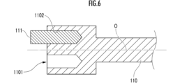
- first pin mounting hole 1101 and a second pin mounting hole having different eccentricities with respect to the central axis O of the rotating member 110 are provided at the tip of the rotating member 110. 1102 may be formed.
- the eccentricity of first pin mounting hole 1101 is smaller than the eccentricity of second pin mounting hole 1102 .
- a cam pin 111 is selectively mounted and fixed in each of the first pin mounting hole 1101 and the second pin mounting hole 1102 .
- the cam pin 111 and the cam hole 21 or the cam groove 211 are designed such that the size of the cam hole 21 or the cam groove 211 is larger than the size of the cam pin 111 in each of the axial direction and the circumferential direction of the vibrating cylinder 20 . Therefore, the rotary member 110 is rotationally driven, and a vibration force acts on the vibrating cylinder 20 in its axial direction through the cam pin 111, whereby the vibrating cylinder 20 vibrates or oscillates in the axial direction with respect to the second cylindrical member 12. It reciprocates and vibrates or reciprocates in the circumferential direction. In addition, since the needle portion 42 protruding from the through hole 202 of the vibration cylinder 20 vibrates while bending, the operator applies the vibrating needle portion 42 to the root canal of the patient's tooth to perform root canal treatment or the like. be able to.
Landscapes
- Health & Medical Sciences (AREA)
- Oral & Maxillofacial Surgery (AREA)
- Dentistry (AREA)
- Epidemiology (AREA)
- Life Sciences & Earth Sciences (AREA)
- Animal Behavior & Ethology (AREA)
- General Health & Medical Sciences (AREA)
- Public Health (AREA)
- Veterinary Medicine (AREA)
- Engineering & Computer Science (AREA)
- Biomedical Technology (AREA)
- Neurology (AREA)
- Neurosurgery (AREA)
- Nuclear Medicine, Radiotherapy & Molecular Imaging (AREA)
- Surgery (AREA)
- Dental Tools And Instruments Or Auxiliary Dental Instruments (AREA)
Priority Applications (4)
| Application Number | Priority Date | Filing Date | Title |
|---|---|---|---|
| AU2022329335A AU2022329335B2 (en) | 2021-08-18 | 2022-03-30 | Dental handpiece |
| JP2023542216A JP7656709B2 (ja) | 2021-08-18 | 2022-03-30 | 歯科用ハンドピース |
| US18/017,907 US12551317B2 (en) | 2021-08-18 | 2022-03-30 | Dental handpiece |
| US19/321,669 US20260000480A1 (en) | 2021-08-18 | 2025-09-08 | Dental handpiece |
Applications Claiming Priority (2)
| Application Number | Priority Date | Filing Date | Title |
|---|---|---|---|
| JP2021152626 | 2021-08-18 | ||
| JP2021-152626 | 2021-08-18 |
Related Child Applications (2)
| Application Number | Title | Priority Date | Filing Date |
|---|---|---|---|
| US18/017,907 A-371-Of-International US12551317B2 (en) | 2021-08-18 | 2022-03-30 | Dental handpiece |
| US19/321,669 Division US20260000480A1 (en) | 2021-08-18 | 2025-09-08 | Dental handpiece |
Publications (1)
| Publication Number | Publication Date |
|---|---|
| WO2023021783A1 true WO2023021783A1 (ja) | 2023-02-23 |
Family
ID=85240356
Family Applications (1)
| Application Number | Title | Priority Date | Filing Date |
|---|---|---|---|
| PCT/JP2022/016275 Ceased WO2023021783A1 (ja) | 2021-08-18 | 2022-03-30 | 歯科用ハンドピース |
Country Status (5)
| Country | Link |
|---|---|
| US (2) | US12551317B2 (https=) |
| JP (1) | JP7656709B2 (https=) |
| AU (1) | AU2022329335B2 (https=) |
| TW (1) | TWI795267B (https=) |
| WO (1) | WO2023021783A1 (https=) |
Families Citing this family (1)
| Publication number | Priority date | Publication date | Assignee | Title |
|---|---|---|---|---|
| USD1043984S1 (en) * | 2022-11-23 | 2024-09-24 | Inter-Med, Inc. | Handpiece adapter for dental irrigation device |
Citations (7)
| Publication number | Priority date | Publication date | Assignee | Title |
|---|---|---|---|---|
| JPS6379911U (https=) * | 1986-11-17 | 1988-05-26 | ||
| JPH01313050A (ja) * | 1988-04-26 | 1989-12-18 | Dentatus Internatl Ab | 歯科器具 |
| US6899715B1 (en) * | 1996-07-18 | 2005-05-31 | Implant Innovations, Inc. | Power-driven osteotome tools for compaction of bone tissue |
| JP2012249766A (ja) * | 2011-06-01 | 2012-12-20 | Nakanishi:Kk | 歯科用ハンドピース |
| JP2020081828A (ja) * | 2018-11-30 | 2020-06-04 | 計芳 鈴木 | 往復駆動式根管充填具 |
| JP2020131010A (ja) * | 2019-02-21 | 2020-08-31 | 計芳 鈴木 | 根管治療用の往復動発生具の振動筒、この振動筒を備えた往復動発生具およびキャップ |
| JP2021090718A (ja) * | 2019-12-10 | 2021-06-17 | 計芳 鈴木 | ファイルの往復動発生具およびファイル付きの往復動発生具 |
Family Cites Families (7)
| Publication number | Priority date | Publication date | Assignee | Title |
|---|---|---|---|---|
| US5145369A (en) | 1990-04-23 | 1992-09-08 | L. Paul Lustig | Dental tool driving apparatus having rotating and roto-reciprocating motions |
| JP4942866B2 (ja) | 2000-08-29 | 2012-05-30 | マニー株式会社 | 歯科用ハンドピース |
| JP5840924B2 (ja) | 2011-11-09 | 2016-01-06 | 長田電機工業株式会社 | 歯科治療用マイクロモータハンドピース |
| US9833299B2 (en) | 2013-12-10 | 2017-12-05 | Dentsply International Inc. | Multi-directional handpiece |
| CN107981939A (zh) * | 2017-12-28 | 2018-05-04 | 拉萨含贝医疗科技有限公司 | 牙齿矫正装置 |
| JP6782878B2 (ja) | 2018-05-05 | 2020-11-11 | 計芳 鈴木 | リーマ用の電動式往復動発生具およびリーマ付きの電動式往復動発生具 |
| KR102223344B1 (ko) * | 2019-09-27 | 2021-03-05 | 자인텍 주식회사 | 핸드피스 |
-
2022
- 2022-03-30 AU AU2022329335A patent/AU2022329335B2/en active Active
- 2022-03-30 US US18/017,907 patent/US12551317B2/en active Active
- 2022-03-30 WO PCT/JP2022/016275 patent/WO2023021783A1/ja not_active Ceased
- 2022-03-30 JP JP2023542216A patent/JP7656709B2/ja active Active
- 2022-04-11 TW TW111113617A patent/TWI795267B/zh active
-
2025
- 2025-09-08 US US19/321,669 patent/US20260000480A1/en active Pending
Patent Citations (7)
| Publication number | Priority date | Publication date | Assignee | Title |
|---|---|---|---|---|
| JPS6379911U (https=) * | 1986-11-17 | 1988-05-26 | ||
| JPH01313050A (ja) * | 1988-04-26 | 1989-12-18 | Dentatus Internatl Ab | 歯科器具 |
| US6899715B1 (en) * | 1996-07-18 | 2005-05-31 | Implant Innovations, Inc. | Power-driven osteotome tools for compaction of bone tissue |
| JP2012249766A (ja) * | 2011-06-01 | 2012-12-20 | Nakanishi:Kk | 歯科用ハンドピース |
| JP2020081828A (ja) * | 2018-11-30 | 2020-06-04 | 計芳 鈴木 | 往復駆動式根管充填具 |
| JP2020131010A (ja) * | 2019-02-21 | 2020-08-31 | 計芳 鈴木 | 根管治療用の往復動発生具の振動筒、この振動筒を備えた往復動発生具およびキャップ |
| JP2021090718A (ja) * | 2019-12-10 | 2021-06-17 | 計芳 鈴木 | ファイルの往復動発生具およびファイル付きの往復動発生具 |
Also Published As
| Publication number | Publication date |
|---|---|
| JP7656709B2 (ja) | 2025-04-03 |
| JPWO2023021783A1 (https=) | 2023-02-23 |
| TW202308570A (zh) | 2023-03-01 |
| US20240065804A1 (en) | 2024-02-29 |
| US12551317B2 (en) | 2026-02-17 |
| AU2022329335B2 (en) | 2026-03-19 |
| US20260000480A1 (en) | 2026-01-01 |
| TWI795267B (zh) | 2023-03-01 |
| AU2022329335A1 (en) | 2024-02-29 |
Similar Documents
| Publication | Publication Date | Title |
|---|---|---|
| US10350028B2 (en) | Multi-directional handpiece | |
| JP6924704B2 (ja) | 線維組織除去のための超音波チップを有する外科器具 | |
| JP5726857B2 (ja) | 改良された骨切除器 | |
| JP5851992B2 (ja) | 外科用やすり | |
| US20260000480A1 (en) | Dental handpiece | |
| JP5710620B2 (ja) | 回転運動を往復運動に変換する機構を備えた外科用やすり器具構造 | |
| JP5840924B2 (ja) | 歯科治療用マイクロモータハンドピース | |
| EP4096564A1 (en) | Tool for a medical treatment, tool tip, moving part and/or handpiece for such a tool and method for producing such a tool for a medical treatment | |
| US8202087B2 (en) | Grinding tip for a vibrational dental instrument | |
| EP4096565A1 (en) | Tool for a medical treatment, tool tip, moving part and/or handpiece for such a tool and method for producing such a tool for a medical treatment | |
| WO2023032337A1 (ja) | 歯科用ピースおよびその製造方法ならびに歯科用ハンドピース | |
| JP2002514933A (ja) | 後充填用穴形成のための歯内治療器具 | |
| US1335825A (en) | Tooth-polishing device | |
| WO2022196783A1 (ja) | 歯科用ハンドピース | |
| JP7774191B1 (ja) | 歯科用ハンドピース | |
| JPWO2020170999A1 (ja) | 針状根管治療具と歯科治療器具 | |
| JP2023067702A (ja) | 歯科用ハンドピースに用いるリーマ、リーマの製造方法及びこのリーマを備えた歯科用ハンドピース | |
| KR20100090398A (ko) | 임플란트 시술용 드릴장치 |
Legal Events
| Date | Code | Title | Description |
|---|---|---|---|
| WWE | Wipo information: entry into national phase |
Ref document number: 18017907 Country of ref document: US |
|
| 121 | Ep: the epo has been informed by wipo that ep was designated in this application |
Ref document number: 22858107 Country of ref document: EP Kind code of ref document: A1 |
|
| WWE | Wipo information: entry into national phase |
Ref document number: 2023542216 Country of ref document: JP |
|
| WWE | Wipo information: entry into national phase |
Ref document number: 202447009230 Country of ref document: IN |
|
| WWE | Wipo information: entry into national phase |
Ref document number: AU2022329335 Country of ref document: AU |
|
| WWE | Wipo information: entry into national phase |
Ref document number: 2401000928 Country of ref document: TH |
|
| ENP | Entry into the national phase |
Ref document number: 2022329335 Country of ref document: AU Date of ref document: 20220330 Kind code of ref document: A |
|
| NENP | Non-entry into the national phase |
Ref country code: DE |
|
| WWE | Wipo information: entry into national phase |
Ref document number: 11202400903W Country of ref document: SG |
|
| 122 | Ep: pct application non-entry in european phase |
Ref document number: 22858107 Country of ref document: EP Kind code of ref document: A1 |
|
| WWG | Wipo information: grant in national office |
Ref document number: 18017907 Country of ref document: US |