WO2023021783A1 - Dental handpiece - Google Patents
Dental handpiece Download PDFInfo
- Publication number
- WO2023021783A1 WO2023021783A1 PCT/JP2022/016275 JP2022016275W WO2023021783A1 WO 2023021783 A1 WO2023021783 A1 WO 2023021783A1 JP 2022016275 W JP2022016275 W JP 2022016275W WO 2023021783 A1 WO2023021783 A1 WO 2023021783A1
- Authority
- WO
- WIPO (PCT)
- Prior art keywords
- cam
- dental handpiece
- vibrating
- vibrating cylinder
- axial direction
- Prior art date
Links
- 239000012791 sliding layer Substances 0.000 claims description 4
- 210000004262 dental pulp cavity Anatomy 0.000 abstract description 21
- 238000005452 bending Methods 0.000 abstract description 5
- 238000010586 diagram Methods 0.000 description 5
- 229910052751 metal Inorganic materials 0.000 description 5
- 239000002184 metal Substances 0.000 description 5
- 229910000838 Al alloy Inorganic materials 0.000 description 2
- OKTJSMMVPCPJKN-UHFFFAOYSA-N Carbon Chemical compound [C] OKTJSMMVPCPJKN-UHFFFAOYSA-N 0.000 description 2
- 229910052799 carbon Inorganic materials 0.000 description 2
- 230000001788 irregular Effects 0.000 description 2
- 239000010935 stainless steel Substances 0.000 description 2
- 229910001220 stainless steel Inorganic materials 0.000 description 2
- 239000000899 Gutta-Percha Substances 0.000 description 1
- 240000000342 Palaquium gutta Species 0.000 description 1
- 239000011247 coating layer Substances 0.000 description 1
- 230000000694 effects Effects 0.000 description 1
- 229920000588 gutta-percha Polymers 0.000 description 1
- 239000010410 layer Substances 0.000 description 1
- 239000000463 material Substances 0.000 description 1
- 210000005036 nerve Anatomy 0.000 description 1
- 239000002631 root canal filling material Substances 0.000 description 1
- 238000007790 scraping Methods 0.000 description 1
Images


Classifications
-
- A—HUMAN NECESSITIES
- A61—MEDICAL OR VETERINARY SCIENCE; HYGIENE
- A61C—DENTISTRY; APPARATUS OR METHODS FOR ORAL OR DENTAL HYGIENE
- A61C1/00—Dental machines for boring or cutting ; General features of dental machines or apparatus, e.g. hand-piece design
- A61C1/08—Machine parts specially adapted for dentistry
- A61C1/12—Angle hand-pieces
-
- A—HUMAN NECESSITIES
- A61—MEDICAL OR VETERINARY SCIENCE; HYGIENE
- A61C—DENTISTRY; APPARATUS OR METHODS FOR ORAL OR DENTAL HYGIENE
- A61C1/00—Dental machines for boring or cutting ; General features of dental machines or apparatus, e.g. hand-piece design
- A61C1/02—Dental machines for boring or cutting ; General features of dental machines or apparatus, e.g. hand-piece design characterised by the drive of the dental tools
- A61C1/07—Dental machines for boring or cutting ; General features of dental machines or apparatus, e.g. hand-piece design characterised by the drive of the dental tools with vibratory drive, e.g. ultrasonic
-
- A—HUMAN NECESSITIES
- A61—MEDICAL OR VETERINARY SCIENCE; HYGIENE
- A61C—DENTISTRY; APPARATUS OR METHODS FOR ORAL OR DENTAL HYGIENE
- A61C1/00—Dental machines for boring or cutting ; General features of dental machines or apparatus, e.g. hand-piece design
- A61C1/08—Machine parts specially adapted for dentistry
- A61C1/18—Flexible shafts; Clutches or the like; Bearings or lubricating arrangements; Drives or transmissions
- A61C1/185—Drives or transmissions
Definitions
- the present invention relates to a dental handpiece for driving a dental piece such as a file and/or reamer attached to the tip to treat the root canal of a tooth.
- a dental piece for root canal treatment such as scraping the wall of the root of a patient's decayed tooth, removing a pus block and/or filling material stuck at the tip of the root, and/or removing the nerve.
- files and/or reamers are used.
- gutta-percha root canal filling material
- an object of the present invention is to provide a wall dental handpiece that can improve the efficiency of cutting the root canal of a tooth using a dental piece such as a reamer.
- the dental handpiece of the present invention is a first tubular member; a second tubular member having a side wall formed with a communication hole communicating with the internal space of the first tubular member and connected to one end of the first tubular member at the side wall; A dental piece having a needle base and a needle extending from the needle base supports the needle base in a state in which the needle is projected into an external space, and is coaxially inserted through the second cylindrical member.
- a vibrating cylinder with a rotary member arranged in the internal space of the first tubular member such that one end faces the internal space of the second tubular member through the communication hole; an actuator that rotates the rotating member about a central axis.
- one end of the rotating member is provided with a cam protrusion projecting at a position eccentric to the central axis of the rotating member,
- a cam recess into which the cam protrusion is fitted is formed on the outside of the side wall of the vibrating cylinder,
- the cam concave portion is formed so that the cam convex portion of the rotary member can be relatively displaced in the circumferential direction of the vibrating cylinder.
- the cam recess forms an annular cam groove that extends along the entire circumference of the outer side wall of the vibrating cylinder, or a cam groove that extends continuously along a portion of the outer side wall of the vibrating cylinder in the circumferential direction. It is preferable that
- the cam recess is formed outside the side wall of the vibrating cylinder so that the width of the cam recess in the axial direction of the vibrating cylinder varies in the circumferential direction of the vibrating cylinder.
- At least one side surface of a pair of side surfaces of the cam recess that face each other in the axial direction of the vibrating cylinder is formed as a wavy surface.
- At least one side surface of a pair of side surfaces of the cam recess that face each other in the axial direction of the vibrating cylinder is formed as a gear surface having a plurality of teeth
- At least part of the side surface of the cam projection is preferably formed as a gear surface having a plurality of teeth meshing with the gear surface.
- a plurality of mounting holes, into which the cam protrusions are mounted are formed at one end of the rotating member at locations with different eccentricities with respect to the central axis of the rotating member.
- a sliding layer is preferably formed on at least one of the surfaces of the cam protrusion and the cam recess.
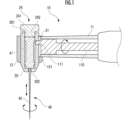
- FIG. 1 is a configuration explanatory diagram of a dental handpiece as a first embodiment of the present invention
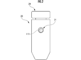
- FIG. 2 is an explanatory diagram of the configuration of the essential parts of the dental handpiece of FIG. 1
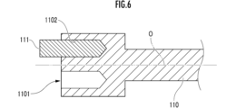
- FIG. 6 is an explanatory diagram of the configuration of a main part of a dental handpiece as a second embodiment of the present invention
- FIG. 10 is an explanatory diagram of the configuration of a main part of a dental handpiece as a third embodiment of the present invention
- FIG. 11 is an explanatory diagram of the configuration of a main part of a dental handpiece as a fourth embodiment of the present invention
- FIG. 4 is an explanatory view of the configuration of a main part of a dental handpiece as another embodiment of the present invention
- a dental handpiece 10 as a first embodiment of the present invention schematically shown in FIG. 1 is configured to drive a reamer 40 (or file) as a dental piece.
- the dental handpiece 10 includes a first tubular member 11 , a second tubular member 12 (supporting tube), and a vibrating tube 20 .
- the first tubular member 11 is formed in a substantially cylindrical shape.
- the second cylindrical member 12 is formed in a substantially cylindrical shape, and the central axis of the second cylindrical member 12 is included in the central axis of the first cylindrical member 11 at a certain angle (for example, within an angle range of 90° to 120°).
- a vibrating cylinder 20 is connected to the distal end portion of the first cylindrical member 11 at its side wall in such a posture as to form or cross the first cylindrical member 11 .
- the vibrating cylinder 20 is positioned substantially coaxially with the second cylindrical member 12 and in a direction parallel to the central axis of the second cylindrical member 12 (FIGS. 1 and 2). vertical direction) is inserted so as to be able to vibrate.
- the first cylindrical member 11, the second cylindrical member 12 and the vibration cylinder 20 are made of metal such as aluminum alloy and stainless steel.
- the first tubular member 11 and the second tubular member 12 are integrally made of the same metal.
- the vibrating cylinder 20 may be made of the same metal as the first tubular member 11 and the second tubular member 12, or may be made of a different metal.
- a substantially cylindrical rotating member 110 is arranged with its center axis parallel or substantially parallel to the longitudinal direction of the first cylindrical member 11 . It is placed in an extended position.
- the tip of the rotating member 110 is formed in a substantially cylindrical shape with a relatively large diameter.
- the distal end portion is provided with a cam pin 111 (cam convex portion) that protrudes in a direction parallel to the central axis of the rotating member 110 eccentrically.
- a pin mounting hole extending parallel to the central axis may be formed in the distal end portion of the rotating member 110, and the cam pin 111 may be detachably mounted in the pin mounting hole.
- the rotating member 110 is configured to be connected to the rotating shaft of the electric motor of the chair unit and driven to rotate about the central axis.
- a switch for ON/OFF-controlling the operation of the electric motor is, for example, a foot switch (not shown).
- the inner space of the first tubular member 11 and the inner space of the second tubular member 12 communicate with each other through a communication hole 121 formed in the side wall of the second tubular member 12. ing.
- a cam hole 21 (cam concave portion) that is locally recessed in the radial direction is formed on the outer side wall of the vibrating cylinder 20 .
- a cam pin 111 of a rotating member 110 is fitted into the cam hole 21 of the vibrating cylinder 20 .
- the cam hole 21 is a substantially cylindrical cam pin so that there is play between the cam pin 111 and the cam hole 21 in the circumferential and axial directions of the vibrating cylinder 20. It is formed in a substantially circular shape with a diameter larger than that of 111 .
- the respective shapes of the cam pin 111 and the cam hole 21 may be designed in various forms.
- the cam hole 21 may be formed in a substantially elliptical shape in which each of the short diameter and the long diameter is larger than the diameter of the substantially cylindrical cam pin 111 .
- the major axis direction of the elliptical cam hole 21 may be parallel to the axial direction of the vibrating cylinder 20, or may be designed to form a certain angle such as 30° or 90°.
- the cam hole 21 may be formed in a substantially circular shape with a larger diameter than the major axis of the substantially elliptical cylindrical cam pin 111 .
- the major axis direction of the elliptical cam pin 111 may be parallel to the axial direction of the vibrating cylinder 20, or may be designed to form a certain angle such as 30° or 90°.
- a sliding layer for improving slidability (reducing friction force) is formed on at least the outer surface of the cam pin 111 of the rotating member 110 and at least the side surface (or side surface and bottom surface) of the cam hole 21 of the vibration cylinder 20.
- the sliding layer may be composed of a carbon coating layer such as DLC (Diamond-Like Carbon).
- the inner space of the vibrating barrel 20 communicates with the external space through a mounting opening 201 on one end side, and communicates with the external space through a through hole 202 having a smaller diameter than the mounting opening 201 on the other end side. are doing.
- One end of the internal space of the vibration cylinder 20 is closed by attaching the cover member 24 to the mounting opening 201 .
- the lid member 24 is composed of a substantially disk-shaped head portion 241 and a substantially cylindrical mounting portion 242 protruding from one end of the head portion 241 .
- a female thread is formed on the inner side wall of the mounting opening 201 of the vibrating cylinder 20
- a male thread is formed on the side surface of the mounting portion 242 of the cover member 24 to be screwed into the female thread.
- the female thread of the vibrating cylinder 20 and/or the male thread of the lid member 24 may be omitted, and the mounting portion 242 of the lid member 24 may be fitted to the vibrating cylinder 20 by being pressed against the inner side wall of the vibrating cylinder 20 .
- the lid member 24 is made of metal such as aluminum alloy or stainless steel.
- the reamer 40 has a needle base 41 and a needle portion 42 .
- the needle part 42 is fixed to the needle base body 41 so as to protrude in the axial direction from one end side of the substantially cylindrical needle base body 41 .
- the needle portion 42 is formed so as to gradually decrease in diameter from the proximal portion to the distal portion.
- the reamer 40 is attached to the vibrating barrel 20 with the needle base 41 housed in the inner space of the vibrating barrel 20 and the needle portion 42 partially protruding from the through hole 202 .
- One end of the needle base 41 abuts on the stepped portion of the through hole 202 and the other end abuts on the end of the mounting portion 242 of the cover member 24 .
- fixed for Needle 42 may be flexible or bendable.
- the second cylindrical member 12, the vibrating cylinder 20 and the lid member 24 constitute a support mechanism that supports the reamer 40 (dental piece) so as to vibrate.
- the cam pin 111 and the cam hole 21 are designed such that the size of the cam hole 21 is larger than the size of the cam pin 111 in each of the axial direction and the circumferential direction of the vibrating cylinder 20 (see FIG. 2). Therefore, the rotary member 110 is rotationally driven, and a vibration force acts on the vibrating cylinder 20 in its axial direction through the cam pin 111, whereby the vibrating cylinder 20 vibrates or oscillates in the axial direction with respect to the second cylindrical member 12. It reciprocates and vibrates or reciprocates in the circumferential direction.
- the practitioner applies the vibrating needle part 42 to the wall of the root canal of the patient's tooth to perform root canal treatment, etc. can be implemented.
- the cam pin 111 and the cam hole 21 are designed so that the amplitude of the reamer 40 in the axial direction of the second tubular member 12 is any value within the range of 0.4 mm to 2.0 mm. This makes it easier to feed the needle part 42 to the root apex of the root canal.
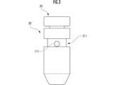
- a substantially annular cam groove 211 extending along the entire circumference is formed.
- a cam pin 111 of the rotating member 110 is fitted in the cam groove 211 of the vibrating cylinder 20 .
- the cam groove 211 extends in the circumferential direction over a portion (for example, 0° to 350°) of the azimuth angle range of 0° to 360° with respect to the central axis of the vibrating cylinder 20, and intermittently at one point. It may be formed on the outside of the side wall of the vibrating cylinder 20 in an annular shape.
- the dental handpiece 10 as the second embodiment of the present invention has the same configuration as the dental handpiece 10 (see FIGS. 1 and 2) as the first embodiment of the present invention except for the above configuration. Common reference numerals are used for common configurations, and description thereof is omitted.
- the cam pin 111 and the cam groove 211 are designed such that the size of the cam groove 211 is larger than the size of the cam pin 111 in each of the axial direction and the circumferential direction of the vibrating cylinder 20 (see FIG. 3). Therefore, the rotary member 110 is rotationally driven, and a vibration force acts on the vibrating cylinder 20 in its axial direction through the cam pin 111, whereby the vibrating cylinder 20 vibrates or oscillates in the axial direction with respect to the second cylindrical member 12. It reciprocates and vibrates or reciprocates in the circumferential direction.
- the needle portion 42 protruding from the through hole 202 of the vibration cylinder 20 vibrates while bending, the operator applies the vibrating needle portion 42 to the root canal of the patient's tooth to perform root canal treatment or the like. be able to.
- a substantially annular cam groove 211 is formed extending over the area.
- a cam pin 111 of the rotating member 110 is fitted in the cam groove 211 of the vibrating cylinder 20 .
- At least one side surface (lower side surface in FIG. 4) of a pair of side surfaces defining the cam groove 211 in the axial direction of the vibrating cylinder 20 is formed as a wavy surface 2110 .
- the amplitude and period of the wavy surface 2110 are designed so that the cam pin 111 can relatively displace along the cam groove 211 in the circumferential direction of the vibrating cylinder 20 .
- a dental handpiece 10 as a third embodiment of the present invention has the same configuration as the dental handpiece 10 (see FIGS. 1 and 2) as the first embodiment of the present invention except for the above configuration. Common reference numerals are used for common configurations, and description thereof is omitted.
- the cam pin 111 and the cam hole 21 or the cam groove 211 are designed such that the size of the cam hole 21 or the cam groove 211 is larger than the size of the cam pin 111 in each of the axial direction and the circumferential direction of the vibrating cylinder 20 . Therefore, the rotary member 110 is rotationally driven, and a vibration force acts on the vibrating cylinder 20 in its axial direction through the cam pin 111, whereby the vibrating cylinder 20 vibrates or oscillates in the axial direction with respect to the second cylindrical member 12. It reciprocates and vibrates or reciprocates in the circumferential direction.
- the needle portion 42 protruding from the through hole 202 of the vibration cylinder 20 vibrates while bending, the operator applies the vibrating needle portion 42 to the root canal of the patient's tooth to perform root canal treatment or the like. be able to.
- the amplitude of the needle portion 42 of the reamer 40 in the axial direction becomes irregular. can give sexuality.
- the needle portion 42 of the reamer 40 can scrape the wall of the root canal of the tooth with some latitude, and the wall can be scraped efficiently.
- a substantially annular cam groove 211 is formed extending over the area.
- a cam pin 111 of the rotating member 110 is fitted in the cam groove 211 of the vibrating cylinder 20 .
- At least one of the pair of side surfaces defining the cam groove 211 in the axial direction of the vibrating cylinder 20 (lower side surface in FIG. 4) is formed as a gear surface 2112 .
- a part of the side wall of the cam pin 111 is formed as a gear surface 1112 that meshes with the gear surface 2112 .
- the gear surface 2112 and the tooth height and tooth pitch of the gear surface 1112 are designed so that the cam pin 111 can relatively displace along the cam groove 211 in the circumferential direction of the vibrating cylinder 20 .
- a dental handpiece 10 as a third embodiment of the present invention has the same configuration as the dental handpiece 10 (see FIGS. 1 and 2) as the first embodiment of the present invention except for the above configuration. Common reference numerals are used for common configurations, and description thereof is omitted.
- the cam pin 111 and the cam hole 21 or the cam groove 211 are designed such that the size of the cam hole 21 or the cam groove 211 is larger than the size of the cam pin 111 in each of the axial direction and the circumferential direction of the vibrating cylinder 20 . Therefore, the rotary member 110 is rotationally driven, and a vibration force acts on the vibrating cylinder 20 in its axial direction through the cam pin 111, whereby the vibrating cylinder 20 vibrates or oscillates in the axial direction with respect to the second cylindrical member 12. It reciprocates and vibrates or reciprocates in the circumferential direction.
- the needle portion 42 protruding from the through hole 202 of the vibration cylinder 20 vibrates while bending, the operator applies the vibrating needle portion 42 to the root canal of the patient's tooth to perform root canal treatment or the like. be able to.
- the gear surface 1112 of the cam pin 111 and the gear surface 2112 of the cam groove 211 come into contact with each other in various manners, thereby making the vibration cylinder 20 and thus the amplitude of the needle portion 42 of the reamer 40 irregular in the axial direction. be able to.
- the needle portion 42 of the reamer 40 can scrape the wall of the root canal of the tooth with some latitude, and the wall can be scraped efficiently.
- first pin mounting hole 1101 and a second pin mounting hole having different eccentricities with respect to the central axis O of the rotating member 110 are provided at the tip of the rotating member 110. 1102 may be formed.
- the eccentricity of first pin mounting hole 1101 is smaller than the eccentricity of second pin mounting hole 1102 .
- a cam pin 111 is selectively mounted and fixed in each of the first pin mounting hole 1101 and the second pin mounting hole 1102 .
- the cam pin 111 and the cam hole 21 or the cam groove 211 are designed such that the size of the cam hole 21 or the cam groove 211 is larger than the size of the cam pin 111 in each of the axial direction and the circumferential direction of the vibrating cylinder 20 . Therefore, the rotary member 110 is rotationally driven, and a vibration force acts on the vibrating cylinder 20 in its axial direction through the cam pin 111, whereby the vibrating cylinder 20 vibrates or oscillates in the axial direction with respect to the second cylindrical member 12. It reciprocates and vibrates or reciprocates in the circumferential direction. In addition, since the needle portion 42 protruding from the through hole 202 of the vibration cylinder 20 vibrates while bending, the operator applies the vibrating needle portion 42 to the root canal of the patient's tooth to perform root canal treatment or the like. be able to.
Abstract
Description
第1筒状部材と、
側壁に前記第1筒状部材の内部空間に連続する連通孔が形成され、当該側壁において前記第1筒状部材の一端部に対して接続されている第2筒状部材と、
針基体および当該針基体から延在する針部を有する歯科用ピースの前記針部を外部空間に突出させた状態で前記針基体を支持し、前記第2筒状部材に同軸の姿勢で挿通されている振動筒と、
前記連通孔を介して一端部が前記第2筒状部材の内部空間に向けられるように、前記第1筒状部材の内部空間に配置されている回転部材と、
前記回転部材を中心軸線まわりに回転駆動させるアクチュエータと、を備えている。 The dental handpiece of the present invention is
a first tubular member;
a second tubular member having a side wall formed with a communication hole communicating with the internal space of the first tubular member and connected to one end of the first tubular member at the side wall;
A dental piece having a needle base and a needle extending from the needle base supports the needle base in a state in which the needle is projected into an external space, and is coaxially inserted through the second cylindrical member. a vibrating cylinder with
a rotary member arranged in the internal space of the first tubular member such that one end faces the internal space of the second tubular member through the communication hole;
an actuator that rotates the rotating member about a central axis.
前記振動筒の側壁外側に前記カム凸部が嵌め込まれるカム凹部が形成され、
前記カム凹部が、前記振動筒の周方向について前記回転部材の前記カム凸部が相対的に変位可能になるように形成されている。 In the dental handpiece of the present invention, one end of the rotating member is provided with a cam protrusion projecting at a position eccentric to the central axis of the rotating member,
A cam recess into which the cam protrusion is fitted is formed on the outside of the side wall of the vibrating cylinder,
The cam concave portion is formed so that the cam convex portion of the rotary member can be relatively displaced in the circumferential direction of the vibrating cylinder.
前記カム凹部が、前記振動筒の側壁外側において全周にわたり延在する環状のカム溝、または、前記振動筒の側壁外側において周方向の一部で連続して延在しているカム溝が形成されていることが好ましい。 In the dental handpiece configured as described above,
The cam recess forms an annular cam groove that extends along the entire circumference of the outer side wall of the vibrating cylinder, or a cam groove that extends continuously along a portion of the outer side wall of the vibrating cylinder in the circumferential direction. It is preferable that
前記カム凹部の前記振動筒の軸線方向の幅が、前記振動筒の周方向について変化するように、前記振動筒の側壁外側に前記カム凹部が形成されていることが好ましい。 In the dental handpiece configured as described above,
It is preferable that the cam recess is formed outside the side wall of the vibrating cylinder so that the width of the cam recess in the axial direction of the vibrating cylinder varies in the circumferential direction of the vibrating cylinder.
前記カム凹部の前記振動筒の軸線方向に対向する一対の側面のうち少なくとも一方の側面が、波形面として形成されていることが好ましい。 In the dental handpiece configured as described above,
It is preferable that at least one side surface of a pair of side surfaces of the cam recess that face each other in the axial direction of the vibrating cylinder is formed as a wavy surface.
前記カム凹部の前記振動筒の軸線方向に対向する一対の側面のうち少なくとも一方の側面が、複数の歯を有するギヤ面として形成され、
前記カム凸部の側面の少なくとも一部が、前記ギヤ面に噛み合う複数の歯を有する歯車面として形成されていることが好ましい。 In the dental handpiece configured as described above,
At least one side surface of a pair of side surfaces of the cam recess that face each other in the axial direction of the vibrating cylinder is formed as a gear surface having a plurality of teeth,
At least part of the side surface of the cam projection is preferably formed as a gear surface having a plurality of teeth meshing with the gear surface.
前記回転部材の一端部に、前記回転部材の中心軸線を基準とした偏心率が相違する箇所に、前記カム凸部が装着される複数の装着穴が形成されていることが好ましい。 In the dental handpiece configured as described above,
It is preferable that a plurality of mounting holes, into which the cam protrusions are mounted, are formed at one end of the rotating member at locations with different eccentricities with respect to the central axis of the rotating member.
前記カム凸部の表面および前記カム凹部の表面のうち少なくとも一方に摺動層が形成されていることが好ましい。 In the dental handpiece configured as described above,
A sliding layer is preferably formed on at least one of the surfaces of the cam protrusion and the cam recess.
図1に模式的に示されている本発明の第1実施形態としての歯科用ハンドピース10は、歯科用ピースとしてのリーマ40(またはファイル)を駆動するように構成されている。歯科用ハンドピース10は、第1筒状部材11と、第2筒状部材12(支持筒)と、振動筒20と、を備えている。第1筒状部材11は略円筒状に形成されている。第2筒状部材12は略円筒状に形成され、当該第2筒状部材12の中心軸線が第1筒状部材11の中心軸線と一定角度(例えば、90°~120°の角度範囲に含まれる)をなすまたは交差するような姿勢で、第1筒状部材11の先端部に対して振動筒20がその側壁において接続されている。第2筒状部材12の内部空間には、振動筒20が第2筒状部材12と略同軸な姿勢で、かつ、第2筒状部材12の中心軸線に平行な方向(図1および図2の上下方向)に振動可能に挿通されている。 (First embodiment)
A
振動筒20の軸線方向および周方向のそれぞれについて、カム穴21のサイズがカムピン111のサイズよりも大きくなるように、カムピン111およびカム穴21が設計されている(図2参照)。このため、回転部材110が回転駆動され、カムピン111を通じて振動筒20に対してその軸線方向に振動力が作用することにより、振動筒20が第2筒状部材12に対して軸線方向に振動または往復運動し、かつ、周方向に振動または往復運動する。また、振動筒20の貫通孔202から突出している針部42が屈曲しながら振動するので、施術者は振動する針部42を患者の歯の根管の壁部に当てて、根管治療等を実施することができる。 (function)
The
本発明の第2実施形態としての歯科用ハンドピース10においては、図3に模式的に示されているように、振動筒20の側壁外側に、第1実施形態のピン穴(図1の符号21参照)に代えて、周方向に全周にわたり延在する略円環状のカム溝211が形成されている。振動筒20のカム溝211には、回転部材110のカムピン111が嵌め込まれている。カム溝211は、振動筒20の中心軸線を基準とした方位角範囲0°~360°のうち一部(例えば、0°~350°)にわたり周方向に延在する、1箇所で断続している環状に振動筒20の側壁外側に形成されていてもよい。 (Second embodiment)
In the
振動筒20の軸線方向および周方向のそれぞれについて、カム溝211のサイズがカムピン111のサイズよりも大きくなるように、カムピン111およびカム溝211が設計されている(図3参照)。このため、回転部材110が回転駆動され、カムピン111を通じて振動筒20に対してその軸線方向に振動力が作用することにより、振動筒20が第2筒状部材12に対して軸線方向に振動または往復運動し、かつ、周方向に振動または往復運動する。また、振動筒20の貫通孔202から突出している針部42が屈曲しながら振動するので、施術者は振動する針部42を患者の歯の根管に当てて、根管治療等を実施することができる。 (function)
The
本発明の第3実施形態としての歯科用ハンドピース10においては、第2実施形態と同様、図4に模式的に示されているように、振動筒20の側壁外側に、周方向に全周にわたり延在する略円環状のカム溝211が形成されている。振動筒20のカム溝211には、回転部材110のカムピン111が嵌め込まれている。カム溝211を振動筒20の軸線方向について画定する一対の側面のうち少なくとも一方の側面(図4では下側の側面)が波形面2110として形成されている。波形面2110の振幅および周期は、カムピン111がカム溝211に沿って振動筒20の周方向に相対的に変位可能になるように設計されている。 (Third Embodiment)
In the
振動筒20の軸線方向および周方向のそれぞれについて、カム穴21またはカム溝211のサイズがカムピン111のサイズよりも大きくなるように、カムピン111およびカム穴21またはカム溝211が設計されている。このため、回転部材110が回転駆動され、カムピン111を通じて振動筒20に対してその軸線方向に振動力が作用することにより、振動筒20が第2筒状部材12に対して軸線方向に振動または往復運動し、かつ、周方向に振動または往復運動する。また、振動筒20の貫通孔202から突出している針部42が屈曲しながら振動するので、施術者は振動する針部42を患者の歯の根管に当てて、根管治療等を実施することができる。 (function)
The
本発明の第4実施形態としての歯科用ハンドピース10においては、第2実施形態と同様、図5に模式的に示されているように、振動筒20の側壁外側に、周方向に全周にわたり延在する略円環状のカム溝211が形成されている。振動筒20のカム溝211には、回転部材110のカムピン111が嵌め込まれている。カム溝211を振動筒20の軸線方向について画定する一対の側面のうち少なくとも一方の側面(図4では下側の側面)がギヤ面2112として形成されている。カムピン111の側壁の一部はギヤ面2112に噛み合う歯車面1112として形成されている。ギヤ面2112および歯車面1112の歯の高さおよび歯のピッチは、カムピン111がカム溝211に沿って振動筒20の周方向に相対的に変位可能になるように設計されている。 (Fourth embodiment)
In the
振動筒20の軸線方向および周方向のそれぞれについて、カム穴21またはカム溝211のサイズがカムピン111のサイズよりも大きくなるように、カムピン111およびカム穴21またはカム溝211が設計されている。このため、回転部材110が回転駆動され、カムピン111を通じて振動筒20に対してその軸線方向に振動力が作用することにより、振動筒20が第2筒状部材12に対して軸線方向に振動または往復運動し、かつ、周方向に振動または往復運動する。また、振動筒20の貫通孔202から突出している針部42が屈曲しながら振動するので、施術者は振動する針部42を患者の歯の根管に当てて、根管治療等を実施することができる。 (function)
The
図6に模式的に示されているように、回転部材110の先端部に、当該回転部材110の中心軸線Oを基準とする偏心率が相違する第1ピン装着穴1101および第2ピン装着穴1102が形成されていてもよい。図6では、第1ピン装着穴1101の偏心率が、第2ピン装着穴1102の偏心率よりも小さい。カムピン111が、第1ピン装着穴1101および第2ピン装着穴1102のそれぞれに選択的に装着かつ固定される。 (Another embodiment of the present invention)
As schematically shown in FIG. 6, a first
11‥第1筒状部材
12‥第2筒状部材(支持筒)
20‥振動筒
21‥カム穴(カム凹部)
22‥ガイドピン
24‥蓋部材
40‥リーマ(歯科用ピース)
41‥針基体
42‥針部
100‥反射防止層
110‥回転部材
111‥カムピン(カム凸部)
121‥連通孔
122‥ガイド溝
201‥装着口
202‥貫通孔
211‥カム溝(カム凹部)
241‥頭部
242‥装着部。
10...
20...
22...
41...
121...Communication hole 122...
241: Head 242: Mounting part.
Claims (7)
- 第1筒状部材と、
側壁に前記第1筒状部材の内部空間に連続する連通孔が形成され、当該側壁において前記第1筒状部材の一端部に対して接続されている第2筒状部材と、
針基体および当該針基体から延在する針部を有する歯科用ピースの前記針部を外部空間に突出させた状態で前記針基体を支持し、前記第2筒状部材に同軸の姿勢で挿通されている振動筒と、
前記連通孔を介して一端部が前記第2筒状部材の内部空間に向けられるように、前記第1筒状部材の内部空間に配置されている回転部材と、
前記回転部材を中心軸線まわりに回転駆動させるアクチュエータと、を備え、
前記回転部材の一端部に、当該回転部材の中心軸線に対して偏心した位置において突出するカム凸部が設けられ、
前記振動筒の側壁外側に前記カム凸部が嵌め込まれるカム凹部が形成され、
前記カム凹部が、前記振動筒の周方向について前記回転部材の前記カム凸部が相対的に変位可能になるように形成されている
歯科用ハンドピース。 a first tubular member;
a second tubular member having a side wall formed with a communication hole communicating with the internal space of the first tubular member and connected to one end of the first tubular member at the side wall;
A dental piece having a needle base and a needle extending from the needle base supports the needle base in a state in which the needle is projected into an external space, and is coaxially inserted through the second cylindrical member. a vibrating cylinder with
a rotary member arranged in the internal space of the first tubular member such that one end faces the internal space of the second tubular member through the communication hole;
an actuator that rotates the rotating member about a central axis,
one end of the rotating member is provided with a cam protrusion projecting at a position eccentric with respect to the central axis of the rotating member;
A cam recess into which the cam protrusion is fitted is formed on the outside of the side wall of the vibrating cylinder,
A dental handpiece, wherein the cam concave portion is formed so that the cam convex portion of the rotating member can be relatively displaced in the circumferential direction of the vibrating cylinder. - 請求項1に記載の歯科用ハンドピースにおいて、
前記カム凹部が、前記振動筒の側壁外側において全周にわたり延在する環状のカム溝、または、前記振動筒の側壁外側において周方向の一部で連続して延在しているカム溝が形成されている
歯科用ハンドピース。 A dental handpiece according to claim 1, wherein
The cam recess forms an annular cam groove that extends along the entire circumference of the outer side wall of the vibrating cylinder, or a cam groove that extends continuously along a portion of the outer side wall of the vibrating cylinder in the circumferential direction. dental handpiece. - 請求項2に記載の歯科用ハンドピースにおいて、
前記カム凹部の前記振動筒の軸線方向の幅が、前記振動筒の周方向について変化するように、前記振動筒の側壁外側に前記カム凹部が形成されている
歯科用ハンドピース。 A dental handpiece according to claim 2, wherein
A dental handpiece, wherein the cam recess is formed on the outer side wall of the vibrating barrel so that the width of the cam recess in the axial direction of the vibrating barrel varies in the circumferential direction of the vibrating barrel. - 請求項3に記載の歯科用ハンドピースにおいて、
前記カム凹部の前記振動筒の軸線方向に対向する一対の側面のうち少なくとも一方の側面が、波形面として形成されている
歯科用ハンドピース。 A dental handpiece according to claim 3, wherein
A dental handpiece, wherein at least one side surface of a pair of side surfaces of the cam recess, which face each other in the axial direction of the vibrating cylinder, is formed as a corrugated surface. - 請求項3に記載の歯科用ハンドピースにおいて、
前記カム凹部の前記振動筒の軸線方向に対向する一対の側面のうち少なくとも一方の側面が、複数の歯を有するギヤ面として形成され、
前記カム凸部の側面の少なくとも一部が、前記ギヤ面に噛み合う複数の歯を有する歯車面として形成されている
歯科用ハンドピース。 A dental handpiece according to claim 3, wherein
At least one side surface of a pair of side surfaces of the cam recess that face each other in the axial direction of the vibrating cylinder is formed as a gear surface having a plurality of teeth,
A dental handpiece, wherein at least a part of a side surface of the cam protrusion is formed as a gear surface having a plurality of teeth meshing with the gear surface. - 請求項1~5のうちいずれか1項に記載の歯科用ハンドピースにおいて、
前記回転部材の一端部に、前記回転部材の中心軸線を基準とした偏心率が相違する箇所に、前記カム凸部が装着される複数の装着穴が形成されている
歯科用ハンドピース。 In the dental handpiece according to any one of claims 1 to 5,
A dental handpiece, wherein a plurality of mounting holes to which the cam projections are mounted are formed at one end of the rotating member at locations with different eccentricities with respect to the central axis of the rotating member. - 請求項1~6のうちいずれか1項に記載の歯科用ハンドピースにおいて、
前記カム凸部の表面および前記カム凹部の表面のうち少なくとも一方に摺動層が形成されている
歯科用ハンドピース。
The dental handpiece according to any one of claims 1 to 6,
A dental handpiece, wherein a sliding layer is formed on at least one of the surface of the cam protrusion and the surface of the cam recess.
Priority Applications (3)
| Application Number | Priority Date | Filing Date | Title |
|---|---|---|---|
| AU2022329335A AU2022329335A1 (en) | 2021-08-18 | 2022-03-30 | Dental handpiece |
| JP2023542216A JPWO2023021783A1 (en) | 2021-08-18 | 2022-03-30 | |
| US18/017,907 US20240065804A1 (en) | 2021-08-18 | 2022-03-30 | Dental handpiece |
Applications Claiming Priority (2)
| Application Number | Priority Date | Filing Date | Title |
|---|---|---|---|
| JP2021152626 | 2021-08-18 | ||
| JP2021-152626 | 2021-08-18 |
Publications (1)
| Publication Number | Publication Date |
|---|---|
| WO2023021783A1 true WO2023021783A1 (en) | 2023-02-23 |
Family
ID=85240356
Family Applications (1)
| Application Number | Title | Priority Date | Filing Date |
|---|---|---|---|
| PCT/JP2022/016275 WO2023021783A1 (en) | 2021-08-18 | 2022-03-30 | Dental handpiece |
Country Status (5)
| Country | Link |
|---|---|
| US (1) | US20240065804A1 (en) |
| JP (1) | JPWO2023021783A1 (en) |
| AU (1) | AU2022329335A1 (en) |
| TW (1) | TWI795267B (en) |
| WO (1) | WO2023021783A1 (en) |
Citations (7)
| Publication number | Priority date | Publication date | Assignee | Title |
|---|---|---|---|---|
| JPS6379911U (en) * | 1986-11-17 | 1988-05-26 | ||
| JPH01313050A (en) * | 1988-04-26 | 1989-12-18 | Dentatus Internatl Ab | Dental instrument |
| US6899715B1 (en) * | 1996-07-18 | 2005-05-31 | Implant Innovations, Inc. | Power-driven osteotome tools for compaction of bone tissue |
| JP2012249766A (en) * | 2011-06-01 | 2012-12-20 | Nakanishi:Kk | Dental hand-piece |
| JP2020081828A (en) * | 2018-11-30 | 2020-06-04 | 計芳 鈴木 | Reciprocative-driven root canal filling tool |
| JP2020131010A (en) * | 2019-02-21 | 2020-08-31 | 計芳 鈴木 | Vibration cylinder of reciprocation generator for root canal treatment, reciprocation generator with this vibration cylinder and cap |
| JP2021090718A (en) * | 2019-12-10 | 2021-06-17 | 計芳 鈴木 | Reciprocating motion generator for file, and reciprocating motion generator with file |
Family Cites Families (3)
| Publication number | Priority date | Publication date | Assignee | Title |
|---|---|---|---|---|
| JP4942866B2 (en) * | 2000-08-29 | 2012-05-30 | マニー株式会社 | Dental handpiece |
| EP3079626B1 (en) * | 2013-12-10 | 2020-08-19 | DENTSPLY SIRONA Inc. | Multi-directional handpiece |
| JP6782878B2 (en) * | 2018-05-05 | 2020-11-11 | 計芳 鈴木 | Electric reciprocating generator for reamer and electric reciprocating generator with reamer |
-
2022
- 2022-03-30 US US18/017,907 patent/US20240065804A1/en active Pending
- 2022-03-30 WO PCT/JP2022/016275 patent/WO2023021783A1/en active Application Filing
- 2022-03-30 JP JP2023542216A patent/JPWO2023021783A1/ja active Pending
- 2022-03-30 AU AU2022329335A patent/AU2022329335A1/en active Pending
- 2022-04-11 TW TW111113617A patent/TWI795267B/en active
Patent Citations (7)
| Publication number | Priority date | Publication date | Assignee | Title |
|---|---|---|---|---|
| JPS6379911U (en) * | 1986-11-17 | 1988-05-26 | ||
| JPH01313050A (en) * | 1988-04-26 | 1989-12-18 | Dentatus Internatl Ab | Dental instrument |
| US6899715B1 (en) * | 1996-07-18 | 2005-05-31 | Implant Innovations, Inc. | Power-driven osteotome tools for compaction of bone tissue |
| JP2012249766A (en) * | 2011-06-01 | 2012-12-20 | Nakanishi:Kk | Dental hand-piece |
| JP2020081828A (en) * | 2018-11-30 | 2020-06-04 | 計芳 鈴木 | Reciprocative-driven root canal filling tool |
| JP2020131010A (en) * | 2019-02-21 | 2020-08-31 | 計芳 鈴木 | Vibration cylinder of reciprocation generator for root canal treatment, reciprocation generator with this vibration cylinder and cap |
| JP2021090718A (en) * | 2019-12-10 | 2021-06-17 | 計芳 鈴木 | Reciprocating motion generator for file, and reciprocating motion generator with file |
Also Published As
| Publication number | Publication date |
|---|---|
| JPWO2023021783A1 (en) | 2023-02-23 |
| TWI795267B (en) | 2023-03-01 |
| AU2022329335A1 (en) | 2024-02-29 |
| TW202308570A (en) | 2023-03-01 |
| US20240065804A1 (en) | 2024-02-29 |
Similar Documents
| Publication | Publication Date | Title |
|---|---|---|
| JP6924704B2 (en) | Surgical instrument with ultrasonic tip for fibrous tissue removal | |
| EP2948096B1 (en) | Ultrasonic tip assembly | |
| EP3079626B1 (en) | Multi-directional handpiece | |
| JP5726857B2 (en) | Improved osteotomy | |
| US8202087B2 (en) | Grinding tip for a vibrational dental instrument | |
| JP5851992B2 (en) | Surgical file | |
| WO2023021783A1 (en) | Dental handpiece | |
| JPH02144051A (en) | Dental equipment | |
| JP2001514923A (en) | Medical or dental instruments and tools for such instruments | |
| US10383702B2 (en) | Angle piece head | |
| JP7416949B2 (en) | Root canal treatment equipment | |
| JP5710620B2 (en) | Surgical file structure with mechanism to convert rotational motion to reciprocating motion | |
| WO2023032337A1 (en) | Dental piece, method for manufacturing same, and dental handpiece | |
| JP2002514933A (en) | Endodontic device for post-filling hole formation | |
| WO2022196783A1 (en) | Dental handpiece | |
| US1335825A (en) | Tooth-polishing device | |
| WO2020170999A1 (en) | Needle-shaped root canal treatment tool, and dental treatment instrument | |
| EP4096565B1 (en) | Tool for a medical treatment | |
| EP4096564A1 (en) | Tool for a medical treatment, tool tip, moving part and/or handpiece for such a tool and method for producing such a tool for a medical treatment | |
| US9833247B2 (en) | Tool for cutting a helical groove in bone | |
| JP2023067702A (en) | Reamer used for dental handpiece, manufacturing method of reamer and dental handpiece including reamer |
Legal Events
| Date | Code | Title | Description |
|---|---|---|---|
| WWE | Wipo information: entry into national phase |
Ref document number: 18017907 Country of ref document: US |
|
| 121 | Ep: the epo has been informed by wipo that ep was designated in this application |
Ref document number: 22858107 Country of ref document: EP Kind code of ref document: A1 |
|
| WWE | Wipo information: entry into national phase |
Ref document number: 2023542216 Country of ref document: JP |
|
| WWE | Wipo information: entry into national phase |
Ref document number: AU2022329335 Country of ref document: AU |
|
| WWE | Wipo information: entry into national phase |
Ref document number: 2401000928 Country of ref document: TH |
|
| ENP | Entry into the national phase |
Ref document number: 2022329335 Country of ref document: AU Date of ref document: 20220330 Kind code of ref document: A |