WO2023013684A1 - Corps fritté en céramique, substrat en céramique, substrat de montage, dispositif électronique et procédé de fabrication de corps fritté en céramique - Google Patents
Corps fritté en céramique, substrat en céramique, substrat de montage, dispositif électronique et procédé de fabrication de corps fritté en céramique Download PDFInfo
- Publication number
- WO2023013684A1 WO2023013684A1 PCT/JP2022/029822 JP2022029822W WO2023013684A1 WO 2023013684 A1 WO2023013684 A1 WO 2023013684A1 JP 2022029822 W JP2022029822 W JP 2022029822W WO 2023013684 A1 WO2023013684 A1 WO 2023013684A1
- Authority
- WO
- WIPO (PCT)
- Prior art keywords
- sintered body
- ceramic sintered
- content
- ceramic
- terms
- Prior art date
Links
- 239000000919 ceramic Substances 0.000 title claims abstract description 161
- 239000000758 substrate Substances 0.000 title claims description 73
- 238000004519 manufacturing process Methods 0.000 title claims description 9
- 238000000034 method Methods 0.000 title description 18
- 239000000654 additive Substances 0.000 claims abstract description 37
- 230000000996 additive effect Effects 0.000 claims abstract description 28
- CPLXHLVBOLITMK-UHFFFAOYSA-N Magnesium oxide Chemical compound [Mg]=O CPLXHLVBOLITMK-UHFFFAOYSA-N 0.000 claims abstract description 27
- GWEVSGVZZGPLCZ-UHFFFAOYSA-N Titan oxide Chemical compound O=[Ti]=O GWEVSGVZZGPLCZ-UHFFFAOYSA-N 0.000 claims abstract description 21
- ODINCKMPIJJUCX-UHFFFAOYSA-N Calcium oxide Chemical compound [Ca]=O ODINCKMPIJJUCX-UHFFFAOYSA-N 0.000 claims abstract description 17
- 229910052742 iron Inorganic materials 0.000 claims abstract description 17
- 229910052719 titanium Inorganic materials 0.000 claims abstract description 17
- VYPSYNLAJGMNEJ-UHFFFAOYSA-N Silicium dioxide Chemical compound O=[Si]=O VYPSYNLAJGMNEJ-UHFFFAOYSA-N 0.000 claims abstract description 12
- PNEYBMLMFCGWSK-UHFFFAOYSA-N aluminium oxide Inorganic materials [O-2].[O-2].[O-2].[Al+3].[Al+3] PNEYBMLMFCGWSK-UHFFFAOYSA-N 0.000 claims abstract description 12
- 239000000377 silicon dioxide Substances 0.000 claims abstract description 6
- 229910052593 corundum Inorganic materials 0.000 claims abstract description 4
- 229910001845 yogo sapphire Inorganic materials 0.000 claims abstract description 4
- JEIPFZHSYJVQDO-UHFFFAOYSA-N iron(III) oxide Inorganic materials O=[Fe]O[Fe]=O JEIPFZHSYJVQDO-UHFFFAOYSA-N 0.000 claims abstract 3
- 229910052681 coesite Inorganic materials 0.000 claims abstract 2
- 229910052906 cristobalite Inorganic materials 0.000 claims abstract 2
- 235000012239 silicon dioxide Nutrition 0.000 claims abstract 2
- 229910052682 stishovite Inorganic materials 0.000 claims abstract 2
- 229910052905 tridymite Inorganic materials 0.000 claims abstract 2
- 229910010413 TiO 2 Inorganic materials 0.000 claims description 51
- 229910018072 Al 2 O 3 Inorganic materials 0.000 claims description 39
- 239000000843 powder Substances 0.000 claims description 36
- 229910052751 metal Inorganic materials 0.000 claims description 29
- 239000002184 metal Substances 0.000 claims description 26
- 229910004298 SiO 2 Inorganic materials 0.000 claims description 8
- 239000011812 mixed powder Substances 0.000 claims description 8
- 239000012535 impurity Substances 0.000 claims description 4
- 238000010304 firing Methods 0.000 claims description 3
- 238000002156 mixing Methods 0.000 claims description 2
- XEEYBQQBJWHFJM-UHFFFAOYSA-N iron Substances [Fe] XEEYBQQBJWHFJM-UHFFFAOYSA-N 0.000 abstract description 80
- 239000010936 titanium Substances 0.000 abstract description 35
- 239000000292 calcium oxide Substances 0.000 abstract description 12
- 235000012255 calcium oxide Nutrition 0.000 abstract description 12
- 239000000395 magnesium oxide Substances 0.000 abstract description 12
- UQSXHKLRYXJYBZ-UHFFFAOYSA-N Iron oxide Chemical compound [Fe]=O UQSXHKLRYXJYBZ-UHFFFAOYSA-N 0.000 abstract description 8
- RTAQQCXQSZGOHL-UHFFFAOYSA-N Titanium Chemical compound [Ti] RTAQQCXQSZGOHL-UHFFFAOYSA-N 0.000 abstract description 6
- OGIDPMRJRNCKJF-UHFFFAOYSA-N titanium oxide Inorganic materials [Ti]=O OGIDPMRJRNCKJF-UHFFFAOYSA-N 0.000 abstract description 5
- 238000013001 point bending Methods 0.000 description 37
- 238000012360 testing method Methods 0.000 description 32
- 238000009826 distribution Methods 0.000 description 17
- 238000004458 analytical method Methods 0.000 description 15
- 230000000052 comparative effect Effects 0.000 description 12
- 230000035939 shock Effects 0.000 description 11
- 239000010949 copper Substances 0.000 description 9
- 229910052802 copper Inorganic materials 0.000 description 8
- 239000002131 composite material Substances 0.000 description 7
- 239000008187 granular material Substances 0.000 description 7
- 238000000465 moulding Methods 0.000 description 7
- RYGMFSIKBFXOCR-UHFFFAOYSA-N Copper Chemical compound [Cu] RYGMFSIKBFXOCR-UHFFFAOYSA-N 0.000 description 6
- 239000000203 mixture Substances 0.000 description 6
- 239000011230 binding agent Substances 0.000 description 5
- 239000002002 slurry Substances 0.000 description 5
- MCMNRKCIXSYSNV-UHFFFAOYSA-N Zirconium dioxide Chemical compound O=[Zr]=O MCMNRKCIXSYSNV-UHFFFAOYSA-N 0.000 description 4
- 239000011575 calcium Substances 0.000 description 4
- 239000011777 magnesium Substances 0.000 description 4
- 238000005245 sintering Methods 0.000 description 4
- 229910052782 aluminium Inorganic materials 0.000 description 3
- 239000013078 crystal Substances 0.000 description 3
- 238000009472 formulation Methods 0.000 description 3
- 230000014509 gene expression Effects 0.000 description 3
- 238000010438 heat treatment Methods 0.000 description 3
- 238000005259 measurement Methods 0.000 description 3
- 239000002904 solvent Substances 0.000 description 3
- XAGFODPZIPBFFR-UHFFFAOYSA-N aluminium Chemical compound [Al] XAGFODPZIPBFFR-UHFFFAOYSA-N 0.000 description 2
- 229910052791 calcium Inorganic materials 0.000 description 2
- 238000005056 compaction Methods 0.000 description 2
- 238000005238 degreasing Methods 0.000 description 2
- 238000010586 diagram Methods 0.000 description 2
- 238000005553 drilling Methods 0.000 description 2
- 239000013022 formulation composition Substances 0.000 description 2
- 229910052749 magnesium Inorganic materials 0.000 description 2
- 229910052760 oxygen Inorganic materials 0.000 description 2
- 239000002245 particle Substances 0.000 description 2
- BASFCYQUMIYNBI-UHFFFAOYSA-N platinum Chemical compound [Pt] BASFCYQUMIYNBI-UHFFFAOYSA-N 0.000 description 2
- 238000002360 preparation method Methods 0.000 description 2
- 239000002994 raw material Substances 0.000 description 2
- 229910052710 silicon Inorganic materials 0.000 description 2
- XLYOFNOQVPJJNP-UHFFFAOYSA-N water Substances O XLYOFNOQVPJJNP-UHFFFAOYSA-N 0.000 description 2
- OYPRJOBELJOOCE-UHFFFAOYSA-N Calcium Chemical compound [Ca] OYPRJOBELJOOCE-UHFFFAOYSA-N 0.000 description 1
- 229910000881 Cu alloy Chemical group 0.000 description 1
- FYYHWMGAXLPEAU-UHFFFAOYSA-N Magnesium Chemical compound [Mg] FYYHWMGAXLPEAU-UHFFFAOYSA-N 0.000 description 1
- 240000007594 Oryza sativa Species 0.000 description 1
- 235000007164 Oryza sativa Nutrition 0.000 description 1
- BQCADISMDOOEFD-UHFFFAOYSA-N Silver Chemical compound [Ag] BQCADISMDOOEFD-UHFFFAOYSA-N 0.000 description 1
- 229910045601 alloy Inorganic materials 0.000 description 1
- 239000000956 alloy Substances 0.000 description 1
- QVGXLLKOCUKJST-UHFFFAOYSA-N atomic oxygen Chemical compound [O] QVGXLLKOCUKJST-UHFFFAOYSA-N 0.000 description 1
- 230000004888 barrier function Effects 0.000 description 1
- 230000005540 biological transmission Effects 0.000 description 1
- 238000005422 blasting Methods 0.000 description 1
- 150000001875 compounds Chemical class 0.000 description 1
- 230000006866 deterioration Effects 0.000 description 1
- 239000006185 dispersion Substances 0.000 description 1
- 238000007606 doctor blade method Methods 0.000 description 1
- 230000000694 effects Effects 0.000 description 1
- 230000005669 field effect Effects 0.000 description 1
- 238000000227 grinding Methods 0.000 description 1
- 230000017525 heat dissipation Effects 0.000 description 1
- 238000009434 installation Methods 0.000 description 1
- 238000009413 insulation Methods 0.000 description 1
- 239000000463 material Substances 0.000 description 1
- 229910044991 metal oxide Inorganic materials 0.000 description 1
- 150000004706 metal oxides Chemical class 0.000 description 1
- 230000004048 modification Effects 0.000 description 1
- 238000012986 modification Methods 0.000 description 1
- 229910000510 noble metal Inorganic materials 0.000 description 1
- 239000001301 oxygen Substances 0.000 description 1
- 229910052697 platinum Inorganic materials 0.000 description 1
- 238000005498 polishing Methods 0.000 description 1
- 238000012545 processing Methods 0.000 description 1
- 238000004445 quantitative analysis Methods 0.000 description 1
- 235000009566 rice Nutrition 0.000 description 1
- 239000004065 semiconductor Substances 0.000 description 1
- 239000010703 silicon Substances 0.000 description 1
- 229910052709 silver Inorganic materials 0.000 description 1
- 239000004332 silver Substances 0.000 description 1
- 239000007921 spray Substances 0.000 description 1
- 238000000859 sublimation Methods 0.000 description 1
- 230000008022 sublimation Effects 0.000 description 1
- RUDFQVOCFDJEEF-UHFFFAOYSA-N yttrium(III) oxide Inorganic materials [O-2].[O-2].[O-2].[Y+3].[Y+3] RUDFQVOCFDJEEF-UHFFFAOYSA-N 0.000 description 1
Images


Classifications
-
- C—CHEMISTRY; METALLURGY
- C04—CEMENTS; CONCRETE; ARTIFICIAL STONE; CERAMICS; REFRACTORIES
- C04B—LIME, MAGNESIA; SLAG; CEMENTS; COMPOSITIONS THEREOF, e.g. MORTARS, CONCRETE OR LIKE BUILDING MATERIALS; ARTIFICIAL STONE; CERAMICS; REFRACTORIES; TREATMENT OF NATURAL STONE
- C04B35/00—Shaped ceramic products characterised by their composition; Ceramics compositions; Processing powders of inorganic compounds preparatory to the manufacturing of ceramic products
- C04B35/01—Shaped ceramic products characterised by their composition; Ceramics compositions; Processing powders of inorganic compounds preparatory to the manufacturing of ceramic products based on oxide ceramics
- C04B35/10—Shaped ceramic products characterised by their composition; Ceramics compositions; Processing powders of inorganic compounds preparatory to the manufacturing of ceramic products based on oxide ceramics based on aluminium oxide
- C04B35/111—Fine ceramics
- C04B35/117—Composites
-
- H—ELECTRICITY
- H05—ELECTRIC TECHNIQUES NOT OTHERWISE PROVIDED FOR
- H05K—PRINTED CIRCUITS; CASINGS OR CONSTRUCTIONAL DETAILS OF ELECTRIC APPARATUS; MANUFACTURE OF ASSEMBLAGES OF ELECTRICAL COMPONENTS
- H05K1/00—Printed circuits
- H05K1/02—Details
- H05K1/03—Use of materials for the substrate
Definitions
- the disclosed embodiments relate to ceramic sintered bodies, ceramic substrates, mounting substrates, electronic devices, and methods for manufacturing ceramic sintered bodies.
- Patent Document 1 discloses a ceramic substrate containing Al 2 O 3 (alumina) as a main component and TiO 2 (titanium oxide) as an additive.
- Cited Document 1 also describes that Al 2 O 3 powder having a particle size of 120 nm to 500 nm is used and has a particle size of 1 ⁇ m or less.
- Patent Document 2 describes a mounting substrate in which a copper plate and an alumina substrate that are in contact with each other are heated in an inert atmosphere, and the copper plate is arranged on the alumina substrate.
- the method disclosed in Patent Document 2 is called an AMB (Active Metal Bonding) method.
- Patent Document 3 describes a mounting board manufactured by using a method of directly bonding ceramic and copper.
- the method disclosed in Patent Document 3 is called a DCB (Direct Copper Bonding) method.
- Patent Document 4 describes a method of manufacturing a circuit board in which a metal plate made of copper or a copper alloy is bonded to the surface of a board made of alumina or the like using a hot press process.
- a ceramic sintered body contains Al 2 O 3 (alumina) and an additive, and is composed of a ceramic sintered body having an Al 2 O 3 content of 94% by mass or more.
- Additives include SiO 2 (silica), CaO (calcia), MgO (magnesia), TiO 2 (titanium oxide) and Fe 2 O 3 (iron oxide).
- the content of Ti (titanium) in terms of TiO 2 in the ceramic sintered body is 120 ppm or more, and the content of Fe (iron) in terms of Fe 2 O 3 is 180 ppm or more.
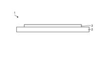
- FIG. 1 is a side view showing an outline of a mounting substrate according to an embodiment.
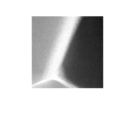
- FIG. 2 is a TEM photograph of the surface of the ceramic sintered body according to the embodiment.
- FIG. 3 is an EDX image showing the analysis results of the distribution of specific elements at the same location as the TEM photograph shown in FIG.
- FIG. 4 is an EDX image showing the analysis results of the distribution of specific elements at the same location as the TEM photograph shown in FIG.
- FIG. 5 is an EDX image showing the analysis results of the distribution of specific elements at the same location as the TEM photograph shown in FIG.
- FIG. 6 is an EDX image showing the analysis result of the distribution of the specific element at the same location as the TEM photograph shown in FIG.
- FIG. 1 is a side view showing an outline of a mounting substrate according to an embodiment.
- FIG. 2 is a TEM photograph of the surface of the ceramic sintered body according to the embodiment.
- FIG. 3 is an EDX image showing the analysis results of the distribution of specific elements at the
- FIG. 7 is an EDX image showing the analysis result of the distribution of the specific element at the same location as the TEM photograph shown in FIG.
- FIG. 8 is an EDX image showing the analysis results of the distribution of the specific element at the same location as the TEM photograph shown in FIG.
- FIG. 9 is an EDX image showing the analysis results of the distribution of the specific element at the same location as the TEM photograph shown in FIG.
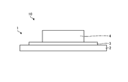
- FIG. 10 is a side view showing an example of the electronic device according to the embodiment;
- FIG. 11 is a diagram showing an example of an approximation function showing the relationship between the blended content and the ICP content.
- FIG. 1 is a side view schematically showing a mounting board 1 according to an embodiment.
- a mounting substrate 1 shown in FIG. 1 includes a ceramic substrate 2 made of a ceramic sintered body and a metal layer 3 . Since the ceramic sintered body is substantially the same as the ceramic substrate 2, reference numerals in the figure are omitted. In other words, the reference numeral 2 in the drawing indicates the ceramic sintered body.
- the ceramic sintered body may be used, for example, for structural members such as rod-shaped bodies, block bodies, and hollow members.
- the ceramic substrate 2 contains Al 2 O 3 (alumina) and an additive, and is made of a ceramic sintered body with an Al 2 O 3 content of 94% by mass or more, and has a thickness of, for example, about 0.2 to 1 mm. is a plate member.
- Additives include SiO 2 (silica), CaO (calcia), MgO (magnesia), TiO 2 (titanium oxide) and Fe 2 O 3 (iron oxide).
- the content of Ti (titanium) in terms of TiO 2 in the ceramic sintered body is 120 ppm or more, and the content of Fe (iron) in terms of Fe 2 O 3 is 180 ppm. That's it. Accordingly, the ceramic substrate 2 using the ceramic sintered body according to the embodiment has high mechanical strength. Moreover, the ceramic sintered body according to the embodiment is excellent in thermal shock resistance.
- the content of Ti in terms of TiO 2 and the content of Fe in terms of Fe 2 O 3 in the ceramic sintered body can be confirmed, for example, by the following methods.
- quantitative analysis of Ti and Fe in the ceramic sintered body is performed using an ICP emission spectrometer (ICP).
- ICP ICP emission spectrometer
- the content (ICP content) converted from the Ti content measured by ICP to TiO 2 , which is an oxide, is obtained, and the content of Fe measured by ICP is converted to Fe 2 O 3 , which is an oxide. Calculate the content (ICP content).
- the reason why the ceramic substrate 2 using the ceramic sintered body according to the embodiment can improve the mechanical strength is considered as follows, for example. That is, by including TiO 2 in the ceramic sintered body forming the ceramic substrate 2 , TiO 2 is located at the grain boundaries of the ceramic sintered body. When the content of TiO 2 in the ceramic sintered body is 120 ppm or more, TiO 2 located at the grain boundaries of the ceramic sintered body functions as a resistor that prevents the progress of cracks that are likely to occur at the grain boundaries. . In addition, TiO 2 located at the grain boundaries of the ceramic sintered body becomes crystal nuclei for sintering aid components (e.g., SiO 2 , CaO and MgO), so that the grain boundaries become polycrystalline and tough. It is possible to suppress the occurrence of cracks. Therefore, the mechanical strength of the ceramic substrate 2 can be improved by adding an appropriate amount of TiO 2 to the ceramic sintered body.
- sintering aid components e.g., SiO 2 , CaO and MgO
- Fe 2 O 3 is located at the grain boundaries of the ceramic sintered body.
- the content of Fe 2 O 3 in the ceramic sintered body is 180 ppm or more
- Fe 2 O 3 located at the grain boundaries of the ceramic sintered body moves the grain boundaries and moves the grain boundaries. causes the phenomenon of moving TiO2 . Therefore, the crystal grain boundaries and TiO 2 can be appropriately dispersed by adding an appropriate amount of Fe 2 O 3 to the ceramic sintered body.
- the mechanical strength of the ceramic substrate 2 improves as the grain boundaries and TiO 2 dispersion progress. Therefore, according to the ceramic substrate 2 according to the embodiment, the mechanical strength of the ceramic substrate 2 can be improved.
- the ceramic sintered body constituting the ceramic substrate 2 according to the embodiment may contain 96% by mass or more and 98% by mass or less of Al 2 O 3 . If the content of Al 2 O 3 is less than 96% by mass, the proportion of sintering aid components (e.g., SiO 2 , CaO and MgO) in the ceramic sintered body increases. Sintering of 2 O 3 to each other can be brittle. If the content of Al 2 O 3 exceeds 98% by mass, it becomes difficult to densify the crystals of Al 2 O 3 , which may reduce the mechanical strength of the ceramic substrate 2 .
- sintering aid components e.g., SiO 2 , CaO and MgO
- the content of Ti in the ceramic sintered body constituting the ceramic substrate 2 according to the embodiment is preferably 350 ppm or less in terms of TiO 2 . If the TiO 2 content exceeds 350 ppm, the distribution of TiO 2 located at the grain boundaries of the ceramic sintered body becomes uneven, which may reduce the mechanical strength of the ceramic substrate 2 .
- the content of Fe in terms of Fe 2 O 3 in the ceramic sintered body constituting the ceramic substrate 2 according to the embodiment is larger than the content of Ti in terms of TiO 2 . If the content of TiO 2 is higher than the content of Fe, the distribution of TiO 2 located at the grain boundaries of the ceramic sintered body becomes uneven, which may reduce the mechanical strength of the ceramic substrate 2. be.
- the content of Fe in the ceramic sintered body that constitutes the ceramic substrate 2 is preferably 410 ppm or less in terms of Fe 2 O 3 .
- the ceramic sintered body constituting the ceramic substrate 2 according to the embodiment does not contain ZrO 2 (zirconia).
- ZrO 2 (zirconia) is relatively expensive. Therefore, since the ceramic sintered body does not contain ZrO 2 , raw material costs can be suppressed.
- the ceramic substrate 2 according to the embodiment can improve thermal conductivity and reduce dielectric loss.
- the thermal conductivity is 23 W/m ⁇ K and the frequency is 1 MHz.
- the dielectric loss at 2 ⁇ 10 ⁇ 4 is 2 ⁇ 10 ⁇ 4 .
- the thermal conductivity is 25 W/m ⁇ K and the dielectric loss at 1 MHz is 0.4 ⁇ 10 ⁇ 4 .
- effective characteristic values are obtained also from the viewpoint of such thermal conductivity and dielectric loss.
- TiO 2 and Fe 2 O 3 in the ceramic sintered body forming the ceramic substrate 2 according to the embodiment are located at grain boundaries.
- the positions of TiO 2 and Fe 2 O 3 in the ceramic sintered body can be determined, for example, by examining the surface of the ceramic substrate 2 with a SEM (scanning electron microscope) or a TEM (transmission electron microscope) with an EDX (energy dispersive X-ray analyzer). ) can be confirmed by observing using
- FIG. 2 is a TEM photograph of the surface of the ceramic substrate 2 according to the embodiment.
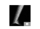
- 3 to 9 are EDX images showing analysis results of the distribution of specific elements at the same locations as the TEM photographs shown in FIG.
- the EDX image in FIG. 3 is a composite image showing the analysis results of the distribution of O (oxygen).
- the EDX image in FIG. 4 is a composite image showing the analysis results of the distribution of Mg (magnesium).
- the EDX image in FIG. 5 is a composite image showing the analysis results of Al (aluminum) distribution.
- the EDX image in FIG. 6 is a composite image showing the analysis results of Si (silicon) distribution.
- the EDX image in FIG. 7 is a composite image showing the analysis results of Ca (calcium) distribution.
- the EDX image in FIG. 8 is a composite image showing the analysis results of Ti (titanium) distribution.
- the EDX image in FIG. 9 is a composite image showing the analysis results of Fe (iron) distribution.
- regions rich in specific elements ie O, Mg, Al, Si, Ca, Ti or Fe are shown in white.
- TiO 2 and Fe 2 O 3 are positioned at the grain boundaries of the ceramic sintered body, thereby suppressing the occurrence and progression of cracks at the grain boundaries. Therefore, according to the ceramic substrate 2 according to the embodiment, it is possible to further improve the mechanical strength.
- a metal layer 3 is located on the ceramic substrate 2 .
- the metal layer 3 is, for example, a metal plate.
- the thickness of the metal plate can be, for example, about 0.1 to 5 mm. Copper or aluminum, for example, can be used as the material of the metal plate.
- the metal plate is, for example, the AMB (Active Metal Bonding) method disclosed in Patent Document 2, the DCB (Direct Copper Bonding) method disclosed in Patent Document 3, or the hot press method disclosed in Patent Document 4, etc. can be used to bond onto a ceramic substrate.
- the conditions for bonding the ceramic substrate 2 and the metal plate 3 are not limited to the conditions within the range disclosed in Patent Documents 2-4.
- the metal layer 3 may be a metal paste containing a noble metal such as copper, silver, or platinum as a main component, for example.
- the thickness of the metal paste can be, for example, about 1 to 40 ⁇ m.
- the metal layer 3 may contain Ti and Fe at least on the ceramic substrate 2 side. Since the ceramic substrate 2 contains Fe and Ti, the bonding strength between the ceramic substrate 2 and the metal layer 3 is increased by diffusing Ti and Fe from the ceramic substrate 2 to the metal layer 3 during bonding. Also, an alloy or compound containing Ti, Fe, or Cu may be located in the metal layer 3 .
- the metal layers 3 may be located on both sides of the ceramic substrate 2 .
- the metal plate 3 may be positioned on one side of the ceramic substrate 2, and the heat dissipation member may be positioned on the other side.
- FIG. 10 is a side view showing an example of the electronic device 10 according to the embodiment.
- the electronic device 10 includes a mounting board 1 and an electronic component 4 positioned on the metal layer 3 of the mounting board 1 .
- a heat sink or flow path member for dissipating heat from the electronic component 4 may be positioned on the surface of the mounting substrate 1 opposite to the surface on which the metal layer 3 is positioned.
- a light emitting diode (LED) element for example, a light emitting diode (LED) element, an insulated gate bipolar transistor (IGBT) element, an intelligent power module (IPM) element, a metal oxide field effect transistor (MOSFET) element, a free wheel
- semiconductor elements such as ring diode (FWD) elements, giant transistor (GTR) elements, Schottky barrier diodes (SBD), sublimation type thermal printer head elements, thermal ink jet printer head elements and heating elements such as Peltier elements be able to.
- Al 2 O 3 (alumina) powder is prepared as a main raw material. Powders of SiO 2 (silica), CaO (calcia), MgO (magnesia), TiO 2 (titanium oxide) and Fe 2 O 3 (iron oxide) are prepared as additives.
- Al 2 O 3 powder and additive powder are mixed to obtain a mixed powder so that the content of Al 2 O 3 is 94% by mass or more.
- the formulation composition at this time is the following composition.
- Al contained in the ceramic substrate 2 is 94% by mass or more in terms of Al 2 O 3 .
- the sum of the values obtained by converting Si to SiO 2 , Ca to CaO, Mg to MgO, Ti to TiO 2 , and Fe to Fe 2 O 3 (that is, additives contained in the ceramic substrate 2) is 1.0% by mass or more6 0% by mass or less.
- the mass ratio of SiO 2 in the additive is, for example, 38% by mass or more and 60% by mass or less.
- the mass ratio of CaO in the additive is, for example, 20% by mass or more and 43% by mass or less.
- the mass ratio of MgO in the additive is, for example, 14% by mass or more and 37% by mass or less.
- the content of Fe contained as an impurity in the Al 2 O 3 powder is 100 to 300 ppm in terms of Fe 2 O 3 .
- the content of Ti in terms of TiO 2 in the additive is 0.48% by mass or more and 1.18% by mass or less
- the content of Fe in terms of Fe 2 O 3 (preparation content) is preferably 0.48% by mass or more.
- the mixture is mixed and pulverized with, for example, a ball mill to prepare a slurry.
- the slurry is spray-dried using a spray dryer to produce granules.
- the granules are molded by a press molding method or a roll compaction molding method, etc. to produce a molded body of the desired shape.
- a sheet-like compact may be produced by molding the slurry by a doctor blade method without producing granules.
- notches, holes, recesses, or the like may be formed in the formed body by drilling, laser, or the like.
- the compact is degreased by heat treatment, and then the compact is fired.
- the firing temperature is, for example, within the range of 1500° C. or higher and 1600° C. or lower.
- the composition after firing is the same as the formulation composition except for TiO 2 and Fe 2 O 3 .
- the ceramic sintered body obtained by sintering the compact may optionally be subjected to polishing, grinding, drilling, laser processing, blasting, or the like. As described above, the ceramic substrate 2 using the ceramic sintered body according to the embodiment is obtained.
- Ceramic sintered bodies (Sample Nos. 3 to 8) of Example 1 were produced as follows. Al 2 O 3 powder and additive powder were mixed so that the respective contents (% by mass) of Al 2 O 3 and additives contained in the ceramic sintered body were the contents shown in Table 1, and a mixed powder was prepared. was made. Next, after adding a solvent and a binder to the prepared powder, granules were produced through a slurry, and the granules were shaped into a desired shape by press molding to produce a compact. Then, after removing the binder component by degreasing, the molded bodies were fired to obtain ceramic sintered bodies (Sample Nos. 3 to 8).
- the underlined ICP contents are the compounded contents (that is, the contents of Ti and Fe in the additive in terms of TiO 2 and Fe 2 O 3 ). and the ICP content.
- FIG. 11 is a diagram showing an example of an approximation function showing the relationship between the blended content and the ICP content.
- FIG. 11 shows an approximation function showing the relationship between the TiO 2 content and the ICP content, and an approximation function showing the relationship between the formulation content and the ICP content for Fe 2 O 3 .
- Each approximation function is created based on each measurement of ICP content versus formulation content.
- the underlined ICP contents numbers can be estimated by applying each formulation content to each approximation function shown in FIG.
- the underlined ICP content values are values obtained by rounding to the nearest whole number.
- JIS piece 3 mm ⁇ 4 mm ⁇ 40 mm test piece
- a JIS piece was produced by a press molding method. Using this JIS piece, a three-point bending strength test and a thermal shock test were performed. The results of the thermal shock test will be described later.
- the three-point bending strength was measured according to JIS R1601-2008.
- the crosshead speed used for measuring the 3-point bending strength was 0.5 mm/min.
- the results of the three-point bending strength test obtained are shown in Table 1.
- the thermal shock test was conducted in accordance with JIS R1648-2002.
- the crosshead speed for the thermal shock test is also 0.5 mm/min.
- Comparative Example 1 A ceramic sintered body (Sample No. 1) of Comparative Example 1 was produced under the same conditions as in Example 1, except that TiO 2 powder was not added as an additive to the Al 2 O 3 powder.
- the ICP content of the metal elements (Ti, Fe) in the obtained ceramic sintered body was measured and estimated in the same manner as described above. Table 1 shows the numerical value of each ICP content obtained. In addition, in Table 1, the ICP content of TiO 2 in the ceramic sintered body is not zero. This is because the Al 2 O 3 powder to be prepared contains TiO 2 as an impurity.
- Example 1 Also, the same three-point bending strength test as in Example 1 was performed on the obtained ceramic sintered body. Table 1 shows the results of the three-point bending strength test.
- Example No. 2 A ceramic sintered body (Sample No. 2) of Comparative Example 2 was produced under the same conditions as in Example 1, except that the Fe 2 O 3 powder was not added as an additive to the Al 2 O 3 powder.
- the ICP content was measured and estimated in the same manner as in Example 1 for the metal elements (Ti, Fe) in the obtained ceramic sintered body.
- Table 1 shows the numerical value of each ICP content obtained.
- the ICP content of Fe 2 O 3 in the ceramic sintered body is not zero. This is because the Al 2 O 3 powder to be prepared contains Fe 2 O 3 as an impurity.
- Example 1 Further, the same three-point bending strength test as in Example 1 was performed on the obtained ceramic sintered body. Table 1 shows the results of the three-point bending strength test.
- the content of Ti (titanium) in terms of TiO 2 in the ceramic sintered body is 120 ppm or more, and the content of Fe (iron) in terms of Fe 2 O 3 is 180 ppm or more. is preferred.
- Ceramic sintered bodies (Sample Nos. 9 to 12) were produced by changing the respective contents (% by mass) of Al 2 O 3 and additives. The conditions were the same as in Example 1 except that the contents (% by mass) of Al 2 O 3 and additives contained in the ceramic sintered body were changed to the contents shown in Table 2. In addition, sample no. 9, 10 and 12 are sample Nos. Same sample as 7, 5 and 8.
- Example 2 shows the numerical value of each ICP content obtained.
- Table 2 shows the results of the three-point bending strength test.
- Sample Nos. 10 and 11 have an Al 2 O 3 content of less than 96% by mass. 9 and sample no .
- the 3-point bending strength was greater than that of 12.
- the ceramic sintered body constituting the ceramic substrate 2 contains 96% by mass or more and 98% by mass or less of Al 2 O 3 .
- the content of Ti in the ceramic sintered body constituting the ceramic substrate 2 is 350 ppm or less in terms of TiO2.
- Ceramic sintered bodies (Sample Nos. 13 and 14) were produced by changing the content of Fe in terms of Fe 2 O 3 and the content of Ti in terms of TiO 2 in the ceramic sintered bodies.
- the content of Fe converted to Fe 2 O 3 and the content of Ti converted to TiO 2 in the ceramic sintered body were changed to the ICP contents shown in Table 3, and the Al 2 contained in the ceramic sintered body
- the conditions are the same as in Example 1 except that the contents (% by mass) of O3 and additives were changed to the contents shown in Table 3.
- Example 1 In addition, the same ICP content as in Example 1 was measured and estimated. Table 3 shows the numerical value of each ICP content obtained.
- test substrate 24 mm x 40 mm x 0.32 mm
- Sample No. 14 has a difference of 20 ppm or less between the ICP content of Fe 2 O 3 and the ICP content of TiO 2 .
- the 3-point bending strength was greater than that of No. 13.
- the content of Fe in the ceramic sintered body that constitutes the ceramic substrate 2 in terms of Fe 2 O 3 is higher than the content of Ti in terms of TiO 2 .
- Example 4 Ceramic sintered bodies of Example 4 (Sample Nos. 18 to 20, 22 and 23) were produced as follows. Al 2 O 3 powder and additive powder were mixed so that the respective contents (% by mass) of Al 2 O 3 and additives contained in the ceramic sintered body were the contents shown in Table 4 to obtain a mixed powder. was made. Here, the content of Ti in terms of TiO 2 and the content of Fe in terms of Fe 2 O 3 in the additive were the blended contents shown in Table 4, respectively. Next, after adding a solvent and a binder to the prepared powder, granules were produced through a slurry, and the granules were shaped into a desired shape by press molding to produce a compact.
- sample Nos. 18 to 20, 22 and 23 are sample Nos. Same sample as 3, 5, 6, 7, 11.
- Example 4 shows the results of the three-point bending strength test.
- Example No. 16 A ceramic sintered body of Comparative Example 3 (Sample No. 16) was produced under the same conditions as in Example 4, except that TiO2 powder was not added as an additive to the Al2O3 powder. In addition, sample no. 16 is sample no. It is the same sample as No.1.
- Example 4 the same three-point bending strength test as in Example 4 was performed on the obtained ceramic sintered body. Table 4 shows the results of the three-point bending strength test.
- Example No. 17 A ceramic sintered body of Comparative Example 4 (Sample No. 17) was produced under the same conditions as in Example 4, except that the Fe 2 O 3 powder was not added as an additive to the Al 2 O 3 powder.
- sample no. 17 is sample no. 2 is the same sample.
- Example 4 the same three-point bending strength test as in Example 4 was performed on the obtained ceramic sintered body. Table 4 shows the results of the three-point bending strength test.
- Comparative Example 5 The ceramic sintered body (Sample No. 21) of Comparative Example 5 was subjected to the same conditions as in Example 4, except that the content of Ti in the additive in terms of TiO2 was changed to the blended content shown in Table 4. made by
- Example 4 the same three-point bending strength test as in Example 4 was performed on the obtained ceramic sintered body. Table 4 shows the results of the three-point bending strength test.
- the content of Ti in terms of TiO 2 in the additive is 0.48% by mass or more and 1.18% by mass or less, and Fe is Fe 2 O 3
- the converted content is preferably 0.48% by mass or more.
- Sample No. in Example 1; 1, 2 and 8 were used to conduct a thermal shock test.
- the results of the thermal shock test are shown in Table 5.
- Sample no. 1 and 2 are comparative examples, and sample Nos. 8 is an example.
- Table 5 also shows the results of evaluating the 3-point bending strength of the JIS pieces without conducting a thermal shock test. The 3-point bending strength of the JIS pieces that were not subjected to the thermal shock test does not indicate the temperature.
- Table 5 after heating the JIS piece to 190°C, 240°C, 265°C, and 290°C, the JIS piece was dropped into water at a water temperature of 10°C and rapidly cooled, and then a three-point bending test was performed for measurement. 3-point bending strength of a JIS piece is shown.
- Sample No. which is a comparative example. 1 and sample no. In No. 2, the three-point bending strength deteriorated by about 30% at 265°C, and the three-point bending strength deteriorated by about 80% at 290°C.
- sample no. In No. 8 the strength deterioration at 265°C was only about 4%, and the three-point bending strength deteriorated by about 61% at 290°C.
- the content of Ti (titanium) in the ceramic sintered body in terms of TiO 2 is 120 ppm or more
- the content of Fe (iron) in terms of Fe 2 O 3 is 120 ppm or more.
- the content is preferably 180 ppm or more.
Abstract
Corps fritté en céramique contenant de l'Al2O3 (alumine) et un additif, et contenant l'Al2O3 en une quantité d'au moins 94 % en masse. L'additif contient du SiO2 (silice), du CaO (oxyde de calcium), du MgO (magnésie), du TiO2 (oxyde de titane), et du Fe2O3 (oxyde de fer). Dans le corps fritté en céramique, la teneur en Ti (titane) est d'au moins 120 ppm en termes de TiO2, et la teneur en Fe (fer) est d'au moins 180 ppm en termes de Fe2O3.
Priority Applications (2)
| Application Number | Priority Date | Filing Date | Title |
|---|---|---|---|
| JP2023534915A JP7336626B2 (ja) | 2021-08-03 | 2022-08-03 | セラミック焼結体、セラミック基板、実装用基板、電子装置及びセラミック焼結体の製造方法 |
| CN202280053813.XA CN117794881A (zh) | 2021-08-03 | 2022-08-03 | 陶瓷烧结体、陶瓷基板、安装用基板、电子设备及陶瓷烧结体的制造方法 |
Applications Claiming Priority (4)
| Application Number | Priority Date | Filing Date | Title |
|---|---|---|---|
| JP2021127812 | 2021-08-03 | ||
| JP2021-127812 | 2021-08-03 | ||
| JP2021177914 | 2021-10-29 | ||
| JP2021-177914 | 2021-10-29 |
Publications (1)
| Publication Number | Publication Date |
|---|---|
| WO2023013684A1 true WO2023013684A1 (fr) | 2023-02-09 |
Family
ID=85155826
Family Applications (1)
| Application Number | Title | Priority Date | Filing Date |
|---|---|---|---|
| PCT/JP2022/029822 WO2023013684A1 (fr) | 2021-08-03 | 2022-08-03 | Corps fritté en céramique, substrat en céramique, substrat de montage, dispositif électronique et procédé de fabrication de corps fritté en céramique |
Country Status (2)
| Country | Link |
|---|---|
| JP (1) | JP7336626B2 (fr) |
| WO (1) | WO2023013684A1 (fr) |
Citations (9)
| Publication number | Priority date | Publication date | Assignee | Title |
|---|---|---|---|---|
| JPS6110053A (ja) * | 1984-06-13 | 1986-01-17 | サボワ リフラクテール | 高アルミナ含量を有する新規耐火物およびその製法 |
| JPS63166774A (ja) | 1986-12-27 | 1988-07-09 | 同和鉱業株式会社 | 銅板とアルミナ基板との接合体の製造方法 |
| JPH05243725A (ja) | 1992-03-03 | 1993-09-21 | Toshiba Corp | セラミック基板と銅の直接接合法 |
| JP2016112576A (ja) * | 2014-12-12 | 2016-06-23 | 品川リフラクトリーズ株式会社 | スライドプレート及びその製造方法 |
| JP2016176988A (ja) * | 2015-03-18 | 2016-10-06 | 京セラ株式会社 | 低反射部材 |
| JP2016532623A (ja) * | 2013-07-26 | 2016-10-20 | サン−ゴバン サントル ド レシェルシュ エ デテュド ユーロペアン | 高アルミナ含量を有する製品 |
| JP2016188170A (ja) * | 2012-01-11 | 2016-11-04 | サン−ゴバン セラミックス アンド プラスティクス,インコーポレイティド | 耐火物及び耐火物を使用したガラス板の形成方法 |
| JP2017218368A (ja) | 2016-06-07 | 2017-12-14 | サムソン エレクトロ−メカニックス カンパニーリミテッド. | 絶縁体組成物及びこれを用いた電子部品の製造方法 |
| JP2020145335A (ja) | 2019-03-07 | 2020-09-10 | 株式会社Fjコンポジット | 回路基板の製造方法 |
-
2022
- 2022-08-03 JP JP2023534915A patent/JP7336626B2/ja active Active
- 2022-08-03 WO PCT/JP2022/029822 patent/WO2023013684A1/fr unknown
Patent Citations (9)
| Publication number | Priority date | Publication date | Assignee | Title |
|---|---|---|---|---|
| JPS6110053A (ja) * | 1984-06-13 | 1986-01-17 | サボワ リフラクテール | 高アルミナ含量を有する新規耐火物およびその製法 |
| JPS63166774A (ja) | 1986-12-27 | 1988-07-09 | 同和鉱業株式会社 | 銅板とアルミナ基板との接合体の製造方法 |
| JPH05243725A (ja) | 1992-03-03 | 1993-09-21 | Toshiba Corp | セラミック基板と銅の直接接合法 |
| JP2016188170A (ja) * | 2012-01-11 | 2016-11-04 | サン−ゴバン セラミックス アンド プラスティクス,インコーポレイティド | 耐火物及び耐火物を使用したガラス板の形成方法 |
| JP2016532623A (ja) * | 2013-07-26 | 2016-10-20 | サン−ゴバン サントル ド レシェルシュ エ デテュド ユーロペアン | 高アルミナ含量を有する製品 |
| JP2016112576A (ja) * | 2014-12-12 | 2016-06-23 | 品川リフラクトリーズ株式会社 | スライドプレート及びその製造方法 |
| JP2016176988A (ja) * | 2015-03-18 | 2016-10-06 | 京セラ株式会社 | 低反射部材 |
| JP2017218368A (ja) | 2016-06-07 | 2017-12-14 | サムソン エレクトロ−メカニックス カンパニーリミテッド. | 絶縁体組成物及びこれを用いた電子部品の製造方法 |
| JP2020145335A (ja) | 2019-03-07 | 2020-09-10 | 株式会社Fjコンポジット | 回路基板の製造方法 |
Also Published As
| Publication number | Publication date |
|---|---|
| JP7336626B2 (ja) | 2023-08-31 |
| JPWO2023013684A1 (fr) | 2023-02-09 |
Similar Documents
| Publication | Publication Date | Title |
|---|---|---|
| US8858865B2 (en) | Silicon nitride substrate manufacturing method, silicon nitride substrate, silicon nitride circuit substrate, and semiconductor module | |
| KR101522807B1 (ko) | 세라믹스 회로 기판 | |
| JP5850031B2 (ja) | 窒化珪素質焼結体、窒化珪素回路基板及び半導体モジュール | |
| JP2018184333A (ja) | 窒化珪素基板の製造方法、及び窒化珪素基板 | |
| JP3629783B2 (ja) | 回路基板 | |
| JP6496021B2 (ja) | セラミック基板およびこれを用いた実装用基板ならびに電子装置 | |
| WO2015147071A1 (fr) | Élément de passage et module à semi-conducteur | |
| US10566264B2 (en) | Flow path member and semiconductor module | |
| JP5481137B2 (ja) | 窒化珪素・メリライト複合焼結体 | |
| JP5804838B2 (ja) | セラミック接合体 | |
| WO2023013684A1 (fr) | Corps fritté en céramique, substrat en céramique, substrat de montage, dispositif électronique et procédé de fabrication de corps fritté en céramique | |
| WO2018062373A1 (fr) | Résistor, carte de circuit imprimé le comprenant, et dispositif électronique | |
| CN112041286B (zh) | 陶瓷基板和使用了该陶瓷基板的安装用基板以及电子装置 | |
| JP2000128654A (ja) | 窒化ケイ素複合基板 | |
| JP2009215142A (ja) | 窒化珪素基板及びその製造方法並びにそれを使用した窒化珪素回路基板及び半導体モジュール | |
| JP5611554B2 (ja) | 高熱伝導性窒化アルミニウム焼結体、これを用いた基板、回路基板、および半導体装置、ならびに高熱伝導性窒化アルミニウム焼結体の製造方法 | |
| JP5031541B2 (ja) | 窒化珪素質焼結体および回路基板ならびにパワー半導体モジュール | |
| JP2004262756A (ja) | 窒化ケイ素質粉末、窒化ケイ素質焼結体及びこれを用いた電子部品用回路基板 | |
| CN117794881A (zh) | 陶瓷烧结体、陶瓷基板、安装用基板、电子设备及陶瓷烧结体的制造方法 | |
| JP7035220B2 (ja) | セラミックス焼結体及び半導体装置用基板 | |
| JPH0524930A (ja) | AlN焼結体およびその製造方法 | |
| JPH11100274A (ja) | 窒化珪素質焼結体、その製造方法及びそれを用いた回路基板 | |
| JP2002293641A (ja) | 窒化ケイ素質焼結体 | |
| JP4868641B2 (ja) | 窒化アルミニウム基板の製造方法 | |
| JP2021130595A (ja) | 窒化珪素基板及びパワーモジュール |
Legal Events
| Date | Code | Title | Description |
|---|---|---|---|
| 121 | Ep: the epo has been informed by wipo that ep was designated in this application |
Ref document number: 22853103 Country of ref document: EP Kind code of ref document: A1 |
|
| ENP | Entry into the national phase |
Ref document number: 2023534915 Country of ref document: JP Kind code of ref document: A |
|
| NENP | Non-entry into the national phase |
Ref country code: DE |
|
| ENP | Entry into the national phase |
Ref document number: 2022853103 Country of ref document: EP Effective date: 20240304 |