WO2023013602A1 - 照明装置を備えた装置、及び、照明装置を備えたパネル部材 - Google Patents
照明装置を備えた装置、及び、照明装置を備えたパネル部材 Download PDFInfo
- Publication number
- WO2023013602A1 WO2023013602A1 PCT/JP2022/029542 JP2022029542W WO2023013602A1 WO 2023013602 A1 WO2023013602 A1 WO 2023013602A1 JP 2022029542 W JP2022029542 W JP 2022029542W WO 2023013602 A1 WO2023013602 A1 WO 2023013602A1
- Authority
- WO
- WIPO (PCT)
- Prior art keywords
- lighting device
- image forming
- forming apparatus
- main body
- apparatus main
- Prior art date
- Legal status (The legal status is an assumption and is not a legal conclusion. Google has not performed a legal analysis and makes no representation as to the accuracy of the status listed.)
- Ceased
Links
Images






Classifications
-
- F—MECHANICAL ENGINEERING; LIGHTING; HEATING; WEAPONS; BLASTING
- F21—LIGHTING
- F21V—FUNCTIONAL FEATURES OR DETAILS OF LIGHTING DEVICES OR SYSTEMS THEREOF; STRUCTURAL COMBINATIONS OF LIGHTING DEVICES WITH OTHER ARTICLES, NOT OTHERWISE PROVIDED FOR
- F21V15/00—Protecting lighting devices from damage
- F21V15/01—Housings, e.g. material or assembling of housing parts
-
- B—PERFORMING OPERATIONS; TRANSPORTING
- B41—PRINTING; LINING MACHINES; TYPEWRITERS; STAMPS
- B41J—TYPEWRITERS; SELECTIVE PRINTING MECHANISMS, i.e. MECHANISMS PRINTING OTHERWISE THAN FROM A FORME; CORRECTION OF TYPOGRAPHICAL ERRORS
- B41J29/00—Details of, or accessories for, typewriters or selective printing mechanisms not otherwise provided for
-
- F—MECHANICAL ENGINEERING; LIGHTING; HEATING; WEAPONS; BLASTING
- F21—LIGHTING
- F21S—NON-PORTABLE LIGHTING DEVICES; SYSTEMS THEREOF; VEHICLE LIGHTING DEVICES SPECIALLY ADAPTED FOR VEHICLE EXTERIORS
- F21S2/00—Systems of lighting devices, not provided for in main groups F21S4/00 - F21S10/00 or F21S19/00, e.g. of modular construction
-
- F—MECHANICAL ENGINEERING; LIGHTING; HEATING; WEAPONS; BLASTING
- F21—LIGHTING
- F21V—FUNCTIONAL FEATURES OR DETAILS OF LIGHTING DEVICES OR SYSTEMS THEREOF; STRUCTURAL COMBINATIONS OF LIGHTING DEVICES WITH OTHER ARTICLES, NOT OTHERWISE PROVIDED FOR
- F21V33/00—Structural combinations of lighting devices with other articles, not otherwise provided for
-
- G—PHYSICS
- G03—PHOTOGRAPHY; CINEMATOGRAPHY; ANALOGOUS TECHNIQUES USING WAVES OTHER THAN OPTICAL WAVES; ELECTROGRAPHY; HOLOGRAPHY
- G03G—ELECTROGRAPHY; ELECTROPHOTOGRAPHY; MAGNETOGRAPHY
- G03G21/00—Arrangements not provided for by groups G03G13/00 - G03G19/00, e.g. cleaning, elimination of residual charge
-
- B—PERFORMING OPERATIONS; TRANSPORTING
- B41—PRINTING; LINING MACHINES; TYPEWRITERS; STAMPS
- B41J—TYPEWRITERS; SELECTIVE PRINTING MECHANISMS, i.e. MECHANISMS PRINTING OTHERWISE THAN FROM A FORME; CORRECTION OF TYPOGRAPHICAL ERRORS
- B41J29/00—Details of, or accessories for, typewriters or selective printing mechanisms not otherwise provided for
- B41J29/18—Mechanisms for rendering the print visible to the operator
- B41J29/19—Mechanisms for rendering the print visible to the operator with reflectors or illuminating devices
-
- F—MECHANICAL ENGINEERING; LIGHTING; HEATING; WEAPONS; BLASTING
- F21—LIGHTING
- F21V—FUNCTIONAL FEATURES OR DETAILS OF LIGHTING DEVICES OR SYSTEMS THEREOF; STRUCTURAL COMBINATIONS OF LIGHTING DEVICES WITH OTHER ARTICLES, NOT OTHERWISE PROVIDED FOR
- F21V3/00—Globes; Bowls; Cover glasses
- F21V3/02—Globes; Bowls; Cover glasses characterised by the shape
-
- F—MECHANICAL ENGINEERING; LIGHTING; HEATING; WEAPONS; BLASTING
- F21—LIGHTING
- F21Y—INDEXING SCHEME ASSOCIATED WITH SUBCLASSES F21K, F21L, F21S and F21V, RELATING TO THE FORM OR THE KIND OF THE LIGHT SOURCES OR OF THE COLOUR OF THE LIGHT EMITTED
- F21Y2105/00—Planar light sources
- F21Y2105/10—Planar light sources comprising a two-dimensional [2D] array of point-like light-generating elements
- F21Y2105/14—Planar light sources comprising a two-dimensional [2D] array of point-like light-generating elements characterised by the overall shape of the two-dimensional [2D] array
- F21Y2105/16—Planar light sources comprising a two-dimensional [2D] array of point-like light-generating elements characterised by the overall shape of the two-dimensional [2D] array square or rectangular, e.g. for light panels
-
- F—MECHANICAL ENGINEERING; LIGHTING; HEATING; WEAPONS; BLASTING
- F21—LIGHTING
- F21Y—INDEXING SCHEME ASSOCIATED WITH SUBCLASSES F21K, F21L, F21S and F21V, RELATING TO THE FORM OR THE KIND OF THE LIGHT SOURCES OR OF THE COLOUR OF THE LIGHT EMITTED
- F21Y2105/00—Planar light sources
- F21Y2105/10—Planar light sources comprising a two-dimensional [2D] array of point-like light-generating elements
- F21Y2105/14—Planar light sources comprising a two-dimensional [2D] array of point-like light-generating elements characterised by the overall shape of the two-dimensional [2D] array
- F21Y2105/18—Planar light sources comprising a two-dimensional [2D] array of point-like light-generating elements characterised by the overall shape of the two-dimensional [2D] array annular; polygonal other than square or rectangular, e.g. for spotlights or for generating an axially symmetrical light beam
-
- F—MECHANICAL ENGINEERING; LIGHTING; HEATING; WEAPONS; BLASTING
- F21—LIGHTING
- F21Y—INDEXING SCHEME ASSOCIATED WITH SUBCLASSES F21K, F21L, F21S and F21V, RELATING TO THE FORM OR THE KIND OF THE LIGHT SOURCES OR OF THE COLOUR OF THE LIGHT EMITTED
- F21Y2115/00—Light-generating elements of semiconductor light sources
- F21Y2115/10—Light-emitting diodes [LED]
-
- F—MECHANICAL ENGINEERING; LIGHTING; HEATING; WEAPONS; BLASTING
- F21—LIGHTING
- F21Y—INDEXING SCHEME ASSOCIATED WITH SUBCLASSES F21K, F21L, F21S and F21V, RELATING TO THE FORM OR THE KIND OF THE LIGHT SOURCES OR OF THE COLOUR OF THE LIGHT EMITTED
- F21Y2115/00—Light-generating elements of semiconductor light sources
- F21Y2115/10—Light-emitting diodes [LED]
- F21Y2115/15—Organic light-emitting diodes [OLED]
Definitions
- the present disclosure relates to an apparatus including an illumination device and a panel member including an illumination device.
- Japanese Design Registration No. 1533194 discloses a printer in which a light-emitting part having a function of notifying a toner bottle that has run out of toner, for example, is provided at the lower inside of the toner bottle mounting hole of each color. It is
- the lighting device may be hidden from the aligned portion side.
- An object of the present disclosure is to improve the visibility of the lighting device from the side of the aligned portion in a configuration in which the aligned portion exists at a position aligned with the lighting device.
- a first aspect includes a lighting device arranged along a first surface of the device, a row portion positioned to line up with the lighting device, and an end surface of the lighting device provided in the row portion to expose the end surface of the lighting device. and an exposed portion.
- the exposed portion is formed continuously from one end on the lighting device side to the other end on the opposite side of the lighting device in the row portion.
- the exposed portion is provided in the row portion on the first surface side of the device.
- the exposed portion is configured by forming an end surface of the row portion on the side of the first surface as an inclined surface.
- the lighting device is arranged at the end of the first surface.
- the lighting device has a rectangular shape along the longitudinal direction of the first surface when viewed from the first surface side.
- the end face on the side opposite to the side on which the row portion of the lighting device is located is exposed.
- the end surface of the lighting device on the side opposite to the side on which the row portion is located is arranged along the edge of the first surface.
- part of the lighting device is exposed on the opposite side of the first surface.
- a plane portion forming a plane, a lighting device arranged along the plane portion, It has an aligned portion that is aligned with the lighting device, and an exposed portion that is provided in the aligned portion and exposes an end face of the lighting device.
- the visibility of the lighting device from the aligned portion side is improved compared to the configuration in which the end surface of the lighting device is covered with the aligned portion.
- the visibility of the lighting device is improved compared to the configuration in which the exposed portion is intermittently formed from one end to the other end.
- the exposed portion of the lighting device is inclined from the first surface side of the device. direction can be seen.
- the configuration of the fourth aspect it is possible to realize a configuration in which the illumination device is exposed with a simple shape that forms an inclined surface.
- the visibility of the lighting device from the end side of the first surface is improved compared to the configuration in which the lighting device is provided in the center of the first surface.
- the length of the lighting device along the short direction of the first surface is suppressed compared to a structure in which the lighting device has a rectangular shape along the short direction of the first surface. can do.
- the visibility of the lighting device from the side opposite to the row portion is improved compared to the configuration in which the end face of the lighting device is covered on the side opposite to the row portion.
- the configuration of the eighth aspect compared to the configuration in which the end face opposite to the side where the row portion is located is on the back side of the end of the first surface of the device, illumination from the side opposite to the row portion Visibility of the device is improved.
- the visibility of the lighting device from the opposite side of the first surface of the device is improved.
- the visibility of the lighting device from the aligned portion side is improved compared to the configuration in which the end face of the lighting device is covered with the aligned portion.
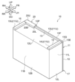
- FIG. 1 is a perspective view of an image forming apparatus having an illumination device according to an exemplary embodiment, viewed from the front right and above;
- FIG. 1 is a perspective view showing an image forming apparatus provided with an illumination device according to an exemplary embodiment viewed from the rear left and above;
- FIG. 1 is a perspective view of an image forming apparatus having an illumination device according to an exemplary embodiment, viewed from the front right and above;
- FIG. 1 is a perspective view of an image forming apparatus having an illumination device according to the present embodiment, viewed from the front right and below;
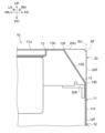
- FIG. 5 is a cross-sectional view taken along line 5-5 of FIG. 3 showing the image forming apparatus provided with the illumination device according to the present embodiment;
- FIG. It is a perspective view which shows the illuminating device which concerns on this embodiment.
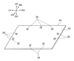
- FIG. 4 is a cross-sectional plan view showing the path of reflected light in the lighting device according to the embodiment; It is a perspective view showing a substrate and a light-emitting element in the lighting device according to the present embodiment.
- FIG. 3 is a perspective view showing a first reflector and light-emitting elements in the lighting device according to the embodiment;
- FIG. 1 is a perspective view showing the image forming apparatus 10 viewed from the front right and above.
- FIG. 2 is a perspective view showing the image forming apparatus 10 viewed from the rear left and above.
- FIG. 3 is a perspective view showing the image forming apparatus 10 viewed from the front left and above.
- FIG. 4 is a perspective view showing the image forming apparatus 10 viewed from the front left and below.
- An arrow UP shown in the figure indicates an upward direction (that is, vertically upward direction), and an arrow DO indicates a downward direction (that is, vertically downward direction).
- An arrow LH shown in the drawing indicates the left direction, and an arrow RH indicates the right direction.
- An arrow FR shown in the drawing indicates the forward direction, and an arrow RR indicates the rearward direction.
- vertical direction may be used to mean “both upward and downward directions” or “either upward or downward direction”.
- Light and left direction may be used to mean “both right and left directions” or “either right or left direction.”
- horizontal direction can also be said to be the lateral direction or the horizontal direction.
- Force-and-aft direction may be used to mean “both forward and rearward directions” or “one of forward and rearward directions.”
- front-rear direction can also be said to be the lateral direction or the horizontal direction.
- the up-down direction, the left-right direction, and the front-rear direction are directions that intersect each other (more specifically, orthogonal directions).
- the symbol with an “X” in the “ ⁇ ” in the figure means an arrow pointing from the front to the back of the paper.
- the symbol “ ⁇ ” written in the “o” in the drawing means an arrow pointing from the back to the front of the paper surface.
- each element is not limited to one, and multiple elements may exist. Also, in the drawings, substantially the same elements are denoted by the same reference numerals, and redundant description in the specification is omitted.
- the image forming apparatus 10 shown in FIGS. 1 to 4 is an image forming apparatus. Specifically, the image forming apparatus 10 includes an image forming apparatus main body 11, an illumination device 20, and an image forming section (not shown).
- the image forming apparatus 10 is an example of "a device provided with a lighting device”. Each part of the image forming apparatus 10 will be described below.
- An image forming apparatus main body 11 shown in FIGS. 1 to 4 is a portion in which each component of the image forming apparatus 10 is provided.
- the image forming apparatus main body 11 specifically has a housing 12 and projecting portions 13 , 14 and 15 .
- the housing 12 is formed in a substantially rectangular parallelepiped shape having a front cover 12F, a right cover 12R, a left cover 12L, a rear cover 12B, an upper cover 12U and a lower cover 12D.
- a front surface 11F, a right surface 11R, a left surface 11L, a rear surface 11B, and a bottom surface 11D of the image forming apparatus main body 11 are formed of a front cover 12F, a right cover 12R, a left cover 12L, a rear cover 12B, an upper cover 12U, and a lower surface, respectively. It is configured by a cover 12D.
- the upper surface 11U of the image forming apparatus main body 11 is configured by upper surfaces 13U, 14U, and 15U of projecting portions 13, 14, and 15, which will be described later.
- the front surface 11 ⁇ /b>F of the image forming apparatus main body 11 is an example of the first surface of the image forming apparatus 10 .
- the front surface 11F has a rectangular shape whose longitudinal direction is the left-right direction.
- the illumination device 20 is formed in a substantially rectangular parallelepiped shape having a front surface 20F, a right side surface 20R, a left side surface 20L, a rear surface 20B, an upper surface 20U and a lower surface (not shown).
- the front surface 20 ⁇ /b>F of the illumination device 20 has a rectangular shape along the longitudinal direction of the front surface 11 ⁇ /b>F of the image forming apparatus main body 11 .
- the lighting device 20 has a fixing piece 20K.
- the lighting device 20 can be attached to the housing 12 by fixing the fixing piece 20K to the front cover 12F, for example.
- the illumination device 20 is arranged along the front surface 11F of the image forming apparatus main body 11 in the front and right portion of the upper cover 12U of the housing 12 .
- the front surface 20 ⁇ /b>F of the lighting device 20 is aligned with the front surface 11 ⁇ /b>F of the image forming apparatus main body 11 .
- the illumination device 20 is arranged at the right end of the front surface 11F, and the right side surface 20R of the illumination device 20 is exposed from the right side surface 11R of the image forming apparatus main body 11.
- a front surface 20 ⁇ /b>F of the illumination device 20 is exposed from a front surface 11 ⁇ /b>F of the image forming apparatus main body 11 .
- the illumination device 20 can be visually recognized from the front and right sides of the image forming apparatus main body 11 .
- the right side surface 20R is the end surface opposite to the side where the projecting portion 13, which is an example of the aligned portion, is located.
- a right side surface 20 ⁇ /b>R of the illumination device 20 is arranged along the edge of the front surface 11 ⁇ /b>F, which is the first surface of the image forming apparatus main body 11 .
- the right side surface 20R of the illumination device 20 and the right side surface 11R of the image forming apparatus main body 11 are substantially flush with each other.
- upper surfaces 13U, 14U, and 15U of the projecting portions 13, 14, and 15 constitute an upper surface 11U of the image forming apparatus main body 11.
- the front surface 20F of the illumination device 20 forms part of the front surface 11F of the image forming apparatus main body 11.
- the front surface 20F of the illumination device 20 is substantially flush with the front cover 12F of the housing 12.
- the upper surface 20U of the illumination device is substantially flush with the upper surface 11U of the image forming apparatus main body 11.
- an upper extended surface SU extending upward from the front surface 11F of the image forming apparatus main body 11 and a front extended surface SF extending forward from the upper surface 11U are indicated by alternate long and short dash lines.
- the lighting device 20 is housed inside the upper extension surface SU and the front extension surface SF, that is, on the housing 12 side.
- the illumination device 20 is located behind the upper extension surface SU and below the front extension surface SF. More specifically, in the example shown in FIG. 5 , the front surface 20F of the illumination device 20 is aligned with the upper extension surface SU, and the upper surface 20U of the illumination device 20 is aligned with the front extension surface SF.
- the side view refers to viewing the object (that is, the illumination device 20 here) from one of the left and right sides toward the other.
- the protruding portion 13 is arranged on the front side of the upper cover 12U and on the left side of the lighting device 20 along the front surface 11F. As shown in FIG. 2, the projecting portion 13 projects upward from the upper cover 12U of the housing 12 and extends in the left-right direction.
- the protruding portion 13 is located in line with the lighting device 20 and is an example of the "line portion".
- protruding portion 13 is an example of a “row portion” because, for example, when illuminating device 20 arranged in front of upper cover 12U is viewed from the side, protruding portion 13 overlaps with illuminating device 20 . It means that there is a part where
- the front end portion 13F of the upper edge is located rearward from the front end portion 13E of the lower edge.
- the projecting portion 13 is formed with an inclined surface 13S that is inclined downward toward the front in a side view. More specifically, in the example shown in FIG. 5, the inclined surface 13S is positioned rearwardly and downwardly away from the upper extension surface SU and the front extension surface SF.
- the inclined surface 13S is planar, and has a flat shape, for example, with no upwardly or forwardly convex or concave portions.
- a panel member 17 is configured including the projecting portion 13 formed with the inclined surface 13S, the front cover 12F, and the lighting device 20. As shown in FIG. In the panel member 17, the front cover 12F is flat and is an example of a flat portion. For example, the panel member 17 may be detachable from the image forming apparatus main body 11 .
- the projecting portion 13 covers the left side surface 20L of the lighting device 20 in side view.
- the protruding portion 13 is formed, as described above, the protruding portion 13 is separated rearward and downward from the upper extended surface SU and the front extended surface SF (that is, it appears to be There is an inclined surface 13S as a missing part. Even if the overhanging portion 13, which is the aligned portion, is arranged side by side with the lighting device 20, a portion of the left side surface 20L of the lighting device 20 is exposed due to the inclined surface 13S.
- part of the lighting device 20 is located forward of the inclined surface 13S of the projecting portion 13, and the left side surface 20L of the lighting device 20 is exposed by the inclined surface 13S. That is, the “exposed portion” of the projecting portion 13 is configured by forming the end surface of the image forming apparatus main body 11 on the front surface 11F side as the inclined surface 13S.
- the “exposed portion” provided in the protruding portion 13 means that the protruding portion 13 is “lined up” as described above, and the “exposed portion” is “exposed” in a side view.
- the inclined surface 13S extends from one end 13P, which is the end on the side of the lighting device 20, to the other end 13Q, which is the end on the opposite side of the lighting device 20, in the projecting portion 13. formed continuously. Therefore, the illumination device 20 can be visually recognized from the left side of the image forming apparatus main body 11 .
- the exposed portion constituted by the inclined surface 13S is provided on the front surface 11F side of the projecting portion 13. As shown in FIG.
- An exposed portion is formed by inclining the end surface of the projecting portion 13 on the front surface 11F side.
- the projecting portion 14 is arranged on the left side of the upper cover 12U and behind the projecting portion 13 along the left side surface 11L.
- the protruding portion 14 protrudes upward from the upper cover 12U and extends in the front-rear direction.
- the projecting portion 15 is arranged on the right side of the upper cover 12U and behind the lighting device 20 along the right side surface 11R.
- the protruding portion 15 protrudes upward from the upper cover 12U of the housing 12 and extends in the front-rear direction.
- the projecting portion 13 may be formed separately from the front cover 12F, or may be integrally formed with the front cover 12F. In the configuration in which the protruding portion 13 is integrally formed with the front cover 12F, the illumination device 20 is fitted in a concave portion on the right side of the protruding portion 13 when viewed from the front face 11F side of the image forming apparatus main body 11. .
- the projecting portion 14 may be formed separately from the left cover 12L, or may be integrally molded. Further, the projecting portion 15 may be formed separately from the right cover 12R, or may be integrally molded.
- the upper cover 12U of the housing 12 is positioned lower than the upper surface 20U of the lighting device 20.
- the image forming apparatus main body 11 is open at the left side with respect to the projecting portion 15 and at the rear side with respect to the illumination device 20 .
- the rear surface 11 ⁇ /b>B which is a part of the lighting device 20 , is exposed from the image forming apparatus main body 11 , and the lighting device 20 can be visually recognized from behind the image forming apparatus main body 11 .
- An image forming unit (not shown) is an example of an image forming unit that forms an image on a recording medium.
- Examples of the image forming unit include an inkjet image forming unit that forms an image on a recording medium using ink, and an electrophotographic image forming unit that forms an image on a recording medium using toner. .
- an image is formed on a recording medium by ejecting ink droplets from an ejection unit onto the recording medium.
- the ink-jet image forming unit may form an image on a recording medium by ejecting ink droplets from an ejection unit onto a transfer body and transferring the ink droplets from the transfer body to the recording medium.
- each step of charging, exposure, development, and transfer is performed to form an image on a recording medium.
- each step of charging, exposure, development, and transfer is performed to form an image on a transfer body, and by transferring the image from the transfer body to a recording medium, an image is formed on the recording medium. may be formed.
- Examples of the image forming unit are not limited to the ink jet image forming unit and the electrophotographic image forming unit described above, and various image forming units can be used.
- FIG. 6 is a perspective view showing the illumination device 20.
- FIG. 7 is a cross-sectional plan view showing the path of reflected light in lighting device 20. As shown in FIG.
- the lighting device 20 shown in FIG. 6 is a device that illuminates its surroundings.
- the illumination device 20 includes a base 30 , a substrate 40 , a light emitting element 28 , a first reflector 50 , a second reflector 60 and a cover 70 .
- the base 30 is a portion on which each component of the lighting device 20 is arranged.
- the table 30 has a plate-like shape with a thickness direction extending in the vertical direction, and is formed in a rectangular shape elongated in the horizontal direction in a plan view.
- a substrate 40 is arranged on the right portion of the upper surface 32 of the table 30 .
- a left portion of the upper surface 32 of the base 30 with respect to the substrate 40 is a reflecting surface 33 that reflects the light from the light emitting element 28 .
- the base 30 is made of, for example, a resin material, and the upper surface 32 including the reflecting surface 33 is made of, for example, a white surface.
- the upper surface 32 including the reflecting surface 33 may be, for example, a plated surface as long as it reflects light.
- the substrate 40 is formed in a rectangular plate shape whose thickness direction is the vertical direction.
- the substrate 40 is configured by a printed circuit board, for example.
- Substrate 40 has a top surface 42 that faces upward. This upper surface 42 is specifically a horizontal surface along the horizontal direction.
- the light-emitting element 28 is, for example, an LED (light emitting diode) element.
- a plurality of light emitting elements 28 are arranged in an elliptical shape on the upper surface 42 of the substrate 40 .
- the plurality of light emitting elements 28 are arranged on the front, rear, left, and right sides of the first reflector 50 in plan view. More specifically, the plurality of light emitting elements 28 are, in plan view, one on each of the front and rear sides of the first reflector 50, two on each of the left and right sides of the first reflector 50, One is arranged in each of the left oblique front, the right oblique front, the left oblique rear, and the right oblique rear with respect to the first reflecting plate 50 . Thus, ten light emitting elements 28 are arranged around the first reflector 50 .
- a planar view refers to a case in which the target (ie, the light emitting element 28 in this case) is viewed from above the target downward.
- the light emitting element 28 irradiates light with an upward spread.
- the light emitting element 28 may be a light source that irradiates at least the first reflecting plate 50 with light.
- the light emitting element 28 can selectively emit light in a plurality of colors such as blue and red, for example.
- the first reflector 50 has the function of reflecting the light from the light emitting element 28 forward, backward, leftward, and rightward. This first reflector 50 is arranged on the upper surface 42 of the substrate 40, as shown in FIG.
- the first reflector 50 is made of a resin material, for example, and has a white surface, for example.
- the surface of the first reflecting plate 50 may be, for example, a plated surface as long as it reflects light.
- the first reflector 50 is formed in an elliptical shape with the left-right direction as the major axis in plan view, and in a cylindrical shape with the up-down direction as the axial direction.
- the first reflecting plate 50 has a curved portion 51 that curves upward from the substrate 40 so as to gradually increase in diameter toward the outer peripheral side, and an upper portion that extends upward from the upper end of the curved portion 51 . 52 and .
- the outer peripheral surface of the curved portion 51 is curved to be convex inward and inclined to the left and right as it goes upward when viewed from the rear.
- the first reflecting plate 50 has reflecting surfaces 57 and 59 that curve in a leftward and rightward direction as it goes upward when viewed from behind. Note that backward viewing refers to a case in which an object (that is, the first reflector 50 in this case) is viewed backward from the front of the object.
- the upper portion 52 is formed in an elliptical cylindrical shape that linearly extends upward from the upper end of the curved portion 51 .
- the outer peripheral surface of the upper portion 52 is an elliptical cylindrical surface without irregularities.
- the curved portion 51 diffuses the light from the light emitting element 28 over a range of 360 degrees including forward, rearward, leftward, and rightward directions, as indicated by the arrow L1 in FIG. reflect.
- the upper part 52 of the first reflector 50 also reflects the light from the light emitting element 28 in a range of 360 degrees including forward, rearward, leftward, and rightward directions.
- the second reflector 60 is arranged to the left of the first reflector 50, as shown in FIG. Then, as shown in FIG. 7, it has a function of reflecting light from the first reflecting plate 50 forward as indicated by an arrow L2.
- the second reflector 60 is made of a resin material, for example, and has a white surface, for example.
- the surface of the second reflector 60 may be plated, for example, as long as it reflects light.
- the second reflector 60 has an extension 61 that extends upward from the top surface 32 of the base 30 .
- the extending portion 61 has a reflecting surface 63 that faces forward and curves forward in a concave shape.
- the extending portion 61 is formed in a plate shape having a thickness direction that intersects the reflecting surface 63 .
- the curvature of the reflecting surface 63 decreases toward the left.
- the front end 60F of the second reflector 60 is arranged behind the front end 50F of the first reflector 50 . That is, the first reflector 50 protrudes further forward than the second reflector 60 .
- the second reflector 60 reflects forward part of the light reflected leftward from the first reflector 50, and reflects the other part of the light to Pass to the left, as referenced by arrow L3.
- the second reflector 60 does not block the other part of the light.
- the second reflector 60 does not block the light reflected backward and to the right from the first reflector 50 and allows the light to be emitted to the outside of the illumination device 20 .
- the front end portion 50F of the first reflector 50 is arranged forward of the front end portion 13F at the upper edge of the projecting portion 13.
- the front end portion 60F of the second reflector 60 is arranged at the same position as the front end portion 13F of the upper edge of the projecting portion 13 in the front-rear direction.
- the cover 70 is arranged in front, rear, left, right, and above the first reflector 50 and the second reflector 60, as shown in FIG.
- the cover 70 is made of, for example, a transparent resin material, and is capable of transmitting light such as reflected light from the first reflector 50 and the second reflector 60 .
- the cover 70 forms a front surface 20F, a right side surface 20R, a left side surface 20L, a rear surface 20B, an upper surface 20U and a lower surface (not shown) of the lighting device 20 .
- the first reflector 50 and the second reflector 60 reflect the light from the light emitting element 28, so that the position where the first reflector 50 is arranged in the left-right direction , illuminate the front with the brightest and gradually darker to the left. That is, the illumination device 20 illuminates with gradation.
- the state having gradation is a state in which the brightness has brightness and the brightness changes continuously.
- a control device (not shown) has a control function of changing the lighting state of the lighting device 20 according to the operating state of the image forming apparatus 10 . Specifically, the control device changes the illumination state of the lighting device 20 between an execution state in which the image forming section 18 is performing an image forming operation and a stopped state in which the image forming section 18 is abnormally stopped. control. Therefore, by confirming the lighting state of the lighting device 20, it is possible to grasp whether the image forming apparatus 10 is in the running state or the stopped state.
- the illumination device 20 is arranged along the front surface 11 ⁇ /b>F of the image forming apparatus main body 11 . Since the front surface 20F of the illumination device 20 is exposed on the front surface 11F side of the image forming apparatus main body 11, the front surface 20F of the illumination device 20 can be visually recognized from the front surface 11F side of the image forming apparatus main body 11.
- the front surface 20F of the lighting device 20 is substantially flush with the front surface 11F of the image forming apparatus main body 11.
- the front surface 11F of the image forming apparatus main body 11 and the front surface 20F of the illumination device 20 A shape with no unevenness is obtained.
- the upper surface 20U of the illumination device is substantially flush with the upper surface 11U of the image forming apparatus main body 11. As shown in FIGS.
- the upper surface 11U of the image forming apparatus main body 11 and the upper surface 20U of the illumination device 20 are arranged. A shape with no unevenness is obtained.
- the right side surface 20R of the lighting device 20 is substantially flush with the right side surface 11R of the image forming apparatus main body 11 .
- the right side surface 20R of the illumination device 20 and the right side surface 11R of the image forming apparatus main body 11 are shifted to the right or left, for example, the right side surface 11R of the image forming apparatus main body 11 and the illumination device are With the right side surface 20R of the device 20, a shape without unevenness can be obtained.
- the projecting portion 13 which is an example of the side-by-side portion, is positioned at a position aligned with the lighting device 20.
- An exposed portion is formed by forming an inclined surface 13S in the projecting portion 13, and a part of the left side surface 20L of the lighting device 20 is exposed. Therefore, in the configuration having the projecting portion 13 arranged side by side with the lighting device 20, the visibility of the lighting device 20 from the side of the projecting portion 13 is improved compared to the case where there is no exposed portion.
- the inclined surface 13S that constitutes the exposed portion continues from one end 13P, which is the end on the side of the lighting device 20, to the other end 13Q, which is the end on the opposite side of the lighting device 20, in the projecting portion 13. . Therefore, the visibility of the lighting device 20 is improved compared to a configuration in which the inclined surface 13S is intermittently formed in the projecting portion 13 from the one end 13P to the other end 13Q.
- the inclined surface 13S is provided on the front surface 11F side of the image forming apparatus main body 11 in the projecting portion 13 .
- the illumination device 20 can be illuminated even from an oblique front side of the image forming apparatus main body 11 on the front surface 11F side.
- the exposed portion on the left side surface 20L can be visually recognized.
- the inclined surface 13S forming the exposed portion is planar in the above example, but may be curved or bent to be convex upward and forward, or curved or bent to be concave. It may be in shape.
- planar inclined surface 13S it is possible to realize a structure having an exposed portion, that is, a structure in which a part of the left side surface 20L of the lighting device 20 is exposed, with a simple shape.
- the lighting device 20 is arranged at the right end of the image forming apparatus main body 11 , and the right side surface 20R of the lighting device 20 is exposed when viewed from the right side surface 11R of the image forming apparatus main body 11 . Therefore, the visibility of the lighting device 20 is improved compared to the configuration in which the right side surface 20R of the lighting device 20 is covered.
- the right side surface 20R of the lighting device 20 is the end surface opposite to the side where the projecting portion 13 is located, and is arranged along the edge of the front surface 11F, which is the first surface of the image forming apparatus main body 11. Since the right side surface 20R of the lighting device 20 is on the same plane as the right side surface 11R of the image forming apparatus main body 11, the right side surface 20R of the lighting device 20 is on the left side of the front surface 11F of the image forming apparatus main body 11. Therefore, the visibility of the right side surface 20R of the illumination device 20 is improved.
- the front surface 20F of the illumination device 20 is exposed when viewed from the front surface 11F side of the image forming apparatus main body 11. Therefore, the visibility of the lighting device 20 is improved compared to the configuration in which the front surface 20F of the lighting device 20 is covered.
- the front surface 20F of the illumination device 20 has a rectangular shape along the longitudinal direction of the front surface 11F of the image forming apparatus main body 11 .
- the front surface 11F of the image forming apparatus main body 11 is The length (that is, height) of lighting device 20 along the lateral direction (that is, vertical direction) can be suppressed.
- the rear surface 11B of the illumination device 20 is exposed from the image forming apparatus main body 11. Visibility from the rear surface 11B side is improved compared to the configuration in which the rear surface of the lighting device 20 is covered.
- the light emitting element 28 is used as an example of the light source in this embodiment, the light source is not limited to this.
- An example of the light source may be a lamp such as a fluorescent lamp, as long as it emits light.
- an LED element is used as an example of the light emitting element 28, but it is not limited to this.
- An example of the light emitting element 28 may be an organic EL (electro-luminescence) element as long as it emits light.
- the illumination device 20 functions as a display device that indicates the operating state of the image forming apparatus 10, but the present invention is not limited to this.
- the illumination device 20 may be used exclusively for the purpose of illuminating the surroundings of the image forming apparatus 10, and the application of the illumination device 20 is not limited.
- the image forming apparatus main body 11 has a rectangular shape with its longitudinal direction extending in the left-right direction when viewed from the front surface 11F side. It is not limited to this. For example, it may be rectangular when viewed from the front surface 11F side and the lateral direction is the lateral direction.
- the shape of the image forming apparatus main body 11 is not limited to a rectangular parallelepiped shape.
- a shape in which a part of the surface of the image forming apparatus main body 11 is curved may be used.
- the lighting device 20 is arranged at the right end portion of the front surface 11F of the image forming apparatus main body 11. It may be arranged at the left end.
- the projecting portion 13 is arranged along the front surface 11F on the right side of the illumination device 20.
- the left side surface 20L of the illumination device 20 is substantially flush with the left side surface 11L of the image forming apparatus main body 11 and is exposed.
- the lighting device 20 may be arranged in the center in the left-right direction on the front surface 11F of the image forming apparatus main body 11 .
- the term "located in the center” means that the right end surface of the lighting device 20 is located to the left of the right side surface 11R of the image forming apparatus main body 11, and the left end surface of the lighting device 20 is located in the image forming apparatus main body. It means that the lighting device 20 is arranged with respect to the image forming apparatus main body 11 in a state of being on the right side of the left side 11 ⁇ /b>L of the image forming apparatus main body 11 .
- the overhanging portion 13 which is an example of the aligned portion, is arranged to the right and to the side of the illumination device 20. obtain.
- the “exposed portions” are the right overhanging portion 13 and the left overhanging portion 13 with respect to the lighting device 20 . If it is provided on either one, a part of the illumination device 20 is exposed at the overhanging portion 13 provided with the exposed portion, so the visibility of the illumination device 20 is improved.
- both the right end surface and the left end surface of the lighting device 20 are exposed.
- the illumination device 20 can be visually recognized from the right and left sides, which is preferable.
- the exposed portion extends from one end of the projecting portion 13 on the lighting device 20 side to the opposite end of the lighting device 20 . It is preferable that it is provided up to the other end which is the portion.
- the lighting device 20 is not limited to the configuration in which it protrudes from the housing 12 .
- the housing 12 may be recessed to provide a recess, and the illumination device 20 may be arranged in this recess.
- the portion of the housing 12 where the recess is not provided is positioned in line with the lighting device 20 and is an example of the “line portion”.
- the front surface 20F of the lighting device 20 is not limited to the configuration in which the front surface 20F of the lighting device 20 is aligned with the upper extended surface SU obtained by extending the front surface 11F of the image forming apparatus main body 11 upward as shown in FIG.
- the front surface 20F of 20 may be slightly forward of the upper extended surface SU.
- the configuration in which the front surface 20F of the illumination device 20 is aligned with the upper extension surface SU and the configuration in which the front surface 20F is slightly forward of the upper extension surface SU are more attractive than the configuration in which the front surface 20F is located behind the upper extension surface SU.
- the lighting device 20 may be aligned with the upper extension surface SU, or may be slightly forward of the upper extension surface SU.
- the image forming apparatus 10 is used as an example of the "apparatus including the illumination device", but the present invention is not limited to this.
- the “apparatus including the lighting device” may be, for example, a manufacturing apparatus for manufacturing various products, and various apparatuses can be used.
Landscapes
- Engineering & Computer Science (AREA)
- General Engineering & Computer Science (AREA)
- Physics & Mathematics (AREA)
- General Physics & Mathematics (AREA)
- Electrophotography Configuration And Component (AREA)
- Accessory Devices And Overall Control Thereof (AREA)
- Control Or Security For Electrophotography (AREA)
- Arrangement Of Elements, Cooling, Sealing, Or The Like Of Lighting Devices (AREA)
- Non-Portable Lighting Devices Or Systems Thereof (AREA)
Abstract
照明装置を備えた装置は、装置の第一面に沿って配置される照明装置と、前記照明装置に並ぶ位置にある並び部分と、前記並び部分に設けられ、前記照明装置の端面を露出させている露出部と、を有する。
Description
本開示は、照明装置を備えた装置、及び、照明装置を備えたパネル部材に関する。
日本国意匠登録第1533194号公報には、それぞれの色のトナーボトル装着孔の下方内側には、例えば、トナーが切れたトナーボトルを知らせる等の機能を有する発光部が設けられているプリンターが開示されている。
照明装置を備えた装置では、照明装置と並ぶ位置に「並び部分」が存在していることがあると、並び部分側からは、この並び部分によって照明装置が隠されてしまうことがある。
本開示は、照明装置と並ぶ位置に並び部分が存在している構成において、並び部分側からの照明装置の視認性を向上させることを目的とする。
第一態様は、装置の第一面に沿って配置されている照明装置と、前記照明装置に並ぶ位置にある並び部分と、前記並び部分に設けられ、前記照明装置の端面を露出させている露出部と、を有する。
第二態様は、前記露出部が、前記並び部分において前記照明装置側の一端から前記照明装置の反対側の他端まで連続して形成されている。
第三態様は、前記露出部が、前記装置の前記第一面側で前記並び部分に設けられている。
第四態様は、前記露出部が、前記並び部分の前記第一面側の端面を傾斜面とすることで構成されている。
第五態様は、前記照明装置は、前記第一面の端部に配置されている。
第六態様は、前記照明装置は、前記第一面側から見て前記第一面の長手方向に沿った長方形状である。
第七態様は、前記照明装置の前記並び部分が位置する側と反対側の端面は露出されている。
第八態様は、前記照明装置の前記並び部分が位置する側と反対側の端面は、前記第一面の端部に沿って配置されている。
第九態様は、前記第一面の反対側において前記照明装置の一部は露出されている。
第十態様は、平面をなす平面部と、前記平面部に沿って配置されている照明装置と、
前記照明装置に並ぶ位置にある並び部分と、前記並び部分に設けられ、前記照明装置の端面を露出させている露出部と、を有する。
前記照明装置に並ぶ位置にある並び部分と、前記並び部分に設けられ、前記照明装置の端面を露出させている露出部と、を有する。
第一態様の構成によれば、並び部分を有する構成において、照明装置の端面が並び部分で覆われている構成と比較して、並び部分側からの照明装置の視認性が向上する。
第二態様の構成によれば、露出部が一端から他端まで断続して形成されている構成と比較して、照明装置の視認性が向上する。
第三態様の構成によれば、露出部が装置の第一面側と異なる位置に設けられている構成と比較して、照明装置の露出している部分を、装置の第一面側から斜め方向に視認できる。
第四態様の構成によれば、傾斜面を形成する単純な形状で、照明装置を露出させている構成を実現できる。
第五態様の構成によれば、照明装置が第一面の中央に設けられている構成と比較して、第一面の端部側からの照明装置の視認性が向上する。
第六態様の構成によれば、照明装置が、第一面の短手方向に沿った長方形状である構造と比較して、第一面の短手方向に沿った照明装置の長さを抑制することができる。
第七態様の構成によれば、並び部分と反対側で照明装置の端面が覆われている構成と比較して、並び部分と反対側からの照明装置の視認性が向上する。
第八態様の構成によれば、並び部分が位置する側と反対側の端面が、装置の第一面の端部よりも奥側にある構成と比較して、並び部分と反対側からの照明装置の視認性が向上する。
第九態様の構成によれば、装置の第一面の反対側からの照明装置の視認性が向上する。
第十態様の構成によれば、並び部分を有する構成において、照明装置の端面が並び部分で覆われている構成と比較して、並び部分側からの照明装置の視認性が向上する。
以下に、本開示に係る実施形態の一例を図面に基づき説明する。
(画像形成装置10)
本実施形態に係る照明装置20を備えた画像形成装置10を説明する。図1は、画像形成装置10を右前方且つ上方から見た場合を示す斜視図である。図2は、画像形成装置10を左後方且つ上方から見た場合を示す斜視図である。図3は、画像形成装置10を左前方且つ上方から見た場合を示す斜視図である。図4は、画像形成装置10を左前方且つ下方から見た場合を示す斜視図である。
本実施形態に係る照明装置20を備えた画像形成装置10を説明する。図1は、画像形成装置10を右前方且つ上方から見た場合を示す斜視図である。図2は、画像形成装置10を左後方且つ上方から見た場合を示す斜視図である。図3は、画像形成装置10を左前方且つ上方から見た場合を示す斜視図である。図4は、画像形成装置10を左前方且つ下方から見た場合を示す斜視図である。
図中に示す矢印UPは、上方向(すなわち、鉛直上方向)を示し、矢印DOは、下方向(すなわち、鉛直下方向)を示す。図中に示す矢印LHは、左方向を示し、矢印RHは、右方向を示す。図中に示す矢印FRは、前方向を示し、矢印RRは、後方向を示す。これらの方向は、説明の便宜上定めた方向であり、装置構成がこれらの方向に限定されるものではない。また、ある基準に対する各位置を示す場合に、基準を省略して示す場合がある。すなわち、たとえば「装置の上方」を、単に「上方」と示す場合がある。
また、下記の説明では、「上下方向」を、「上方向及び下方向の両方向」又は「上方向及び下方向のいずれか一方向」という意味で用いる場合がある。「左右方向」を、「右方向及び左方向の両方向」又は「右方向及び左方向のいずれか一方向」という意味で用いる場合がある。なお、「左右方向」は、横方向、水平方向ともいえる。「前後方向」を、「前方向及び後方向の両方向」又は「前方向及び後方向のいずれか一方向」という意味で用いる場合がある。なお、「前後方向」は、横方向、水平方向ともいえる。また、上下方向、左右方向、前後方向は、互いに交差する方向(具体的には、直交する方向)である。
また、図中の「○」の中に「×」が記載された記号は、紙面の手前から奥へ向かう矢印を意味する。また、図中の「○」の中に「・」が記載された記号は、紙面の奥から手前へ向かう矢印を意味する。
また、明細書中に特段の断りが無い限り、各要素は一つに限定されず、複数存在してもよい。また、図面中では、実質的に同一の要素には同一の符号を付し、明細書における重複説明を省略する。
図1~図4に示される画像形成装置10は、画像を形成する装置である。具体的には、画像形成装置10は、画像形成装置本体11と、照明装置20と、不図示の画像形成部と、を備えている。
画像形成装置10は、「照明装置を備えた装置」の一例である。以下、画像形成装置10の各部について説明する。
(画像形成装置本体11)
図1~図4に示される画像形成装置本体11は、画像形成装置10の各構成部が設けられる部分である。
図1~図4に示される画像形成装置本体11は、画像形成装置10の各構成部が設けられる部分である。
画像形成装置本体11は、具体的には、筐体12と、張出部13、14、15と、を有している。
筐体12は、図1~図4に示されるように、前カバー12F、右カバー12R、左カバー12L、後カバー12B、上カバー12U及び下カバー12Dを有する略直方体形状に形成されている。そして、画像形成装置本体11の前面11F、右側面11R、左側面11L、後面11B、及び下面11Dが、それぞれ、前カバー12F、右カバー12R、左カバー12L、後カバー12B、上カバー12U及び下カバー12Dによって構成されている。また、画像形成装置本体11の上面11Uが、後述する張出部13、14、15の上面13U、14U、15Uによって構成されている。画像形成装置本体11の前面11Fは、画像形成装置10の第一面の一例である。前面11Fは、左右方向を長手方向とする長方形状である。
照明装置20は、前面20F、右側面20R、左側面20L、後面20B、上面20U及び不図示の下面を有する略直方体状に形成されている。照明装置20を画像形成装置本体11の前面11F側から見ると、照明装置20の前面20Fは、画像形成装置本体11の前面11Fの長手方向に沿った長方形状である。
図5に示されるように、照明装置20は固定片20Kを有している。この固定片20Kをたとえば前カバー12Fに固定させることで、照明装置20を筐体12に取り付けることができる。
照明装置20は、筐体12の上カバー12Uにおける前方であって、且つ右方の部分に、画像形成装置本体11の前面11Fに沿って配置されている。画像形成装置本体11を上方から見ると、照明装置20の前面20Fは、画像形成装置本体11の前面11Fと一致した状態となっている。
照明装置20は、前面11Fの右端部に配置されており、照明装置20の右側面20Rは画像形成装置本体11の右側面11Rから露出している。また、照明装置20の前面20Fは、画像形成装置本体11の前面11Fから露出している。これにより、照明装置20は、画像形成装置本体11の前方及び右方から視認可能とされている。
照明装置20において、右側面20Rは、並び部分の一例である張出部13が位置する側と反対側の端面である。照明装置20の右側面20Rは、画像形成装置本体11の第一面である前面11Fの端部に沿って配置されている。換言すれば、照明装置20の右側面20Rは、画像形成装置本体11の右側面11Rと略同一平面にある。
図5に示されるように、張出部13、14、15の上面13U、14U、15Uによって、画像形成装置本体11の上面11Uが構成されている。また、照明装置20の前面20Fは、画像形成装置本体11の前面11Fの一部を成している。図1、図3及び図4に示されるように、照明装置20の前面20Fは、筐体12の前カバー12Fと略同一平面にある。また、図1、図2及び図3に示されるように、照明装置の上面20Uは、画像形成装置本体11の上面11Uと略同一平面にある。
図5には、画像形成装置本体11の前面11Fを上方に延長した上延長面SUと、上面11Uを前方に延長した前延長面SFとが、それぞれ一点鎖線で示されている。照明装置20は、上延長面SU及び前延長面SFに対し内側、すなわち筐体12側に収まっている。図5に示す画像形成装置本体11の側面視では、照明装置20は、上延長面SUよりも後側で、且つ前延長面SFよりも下方に収まっている。より具体的には、図5に示される例では、照明装置20の前面20Fは上延長面SUと一致した位置にあり、照明装置20の上面20Uは、前延長面SFと一致した位置にある。なお、側面視とは、対象(すなわち、ここでは照明装置20)に対する左方及び右方の一方から当該対象を他方へ向かって見ることをいう。
張出部13は、図1~図4に示されるように、上カバー12Uにおける前方であって、照明装置20に対する左方に、前面11Fに沿って配置されている。図2に示されるように、張出部13は、筐体12の上カバー12Uから上方に張り出しており、左右方向に延びている。張出部13は、照明装置20に並ぶ位置にあり、「並び部分」の一例である。ここで、張出部13が「並び部分」の一例である、とは、たとえば上カバー12Uにおける前方に配置された照明装置20を側面視した場合に、張出部13に照明装置20と重なっている部分があるということである。
張出部13では、上縁における前端部13Fが、下縁における前端部13Eよりも後方に位置している。そして、張出部13には、図5にも示されるように、側面視にて、前方に向かうにつれて徐々に下るように傾斜する傾斜面13Sが形成されている。より具体的には、図5に示される例では、傾斜面13Sは、上延長面SU及び前延長面SFからは、後方及び下方に離れた位置にある。
傾斜面13Sは平面状であり、たとえば、上方及び前方に向かって凸となる部分や凹となる部分がない平らな形状である。
そして、傾斜面13Sが形成された張出部13、前カバー12F、及び照明装置20を含んで、パネル部材17が構成されている。パネル部材17において、前カバー12Fは平面をなしており、平面部の一例である。たとえば、画像形成装置本体11において、パネル部材17を着脱できるようにしてもよい。
傾斜面13Sが形成されていない構成の場合には、張出部13が側面視で照明装置20の左側面20Lを覆っている。これに対し、張出部13が形成された構成では、上記したように、張出部13には、上延長面SUと前延長面SFに対し後方及び下方に離れた(すなわち、見かけ上は欠けている)部位として傾斜面13Sが存在している。並び部分である張出部13が照明装置20に並べて配置されていても、傾斜面13Sによって、照明装置20の左側面20Lの一部が露出した状態となっている。
換言すれば、照明装置20の一部は、張出部13の傾斜面13Sよりも前方に位置しており、傾斜面13Sによって、照明装置20の左側面20Lが露出している。すなわち、張出部13の「露出部」が、画像形成装置本体11の前面11F側の端面を傾斜面13Sとすることで構成されている。換言すれば、張出部13に「露出部」が設けられている、とは、上記したように、張出部13が「並び部分」になっている上で、側面視にて、「露出部」が張出部13に設けられていない場合には照明装置20と重なっている部分に、照明装置20の一部が露出した状態となっているように、見かけ上欠けている部分が存在することをいう。
図1~図4に示されるように、傾斜面13Sは、張出部13において照明装置20側の端部である一端13Pから、照明装置20の反対側の端部である他端13Qまで、連続して形成されている。したがって、画像形成装置本体11の左方から照明装置20を視認可能とされている。
図1及び図5に示されるように、傾斜面13Sによって構成されている露出部は、張出部13における前面11F側に設けられている。
そして、張出部13における前面11F側の端面を傾斜させることで、露出部が構成されている。
張出部14は、図1~図4に示されるように、上カバー12Uにおける左方であって、張出部13に対する後方に、左側面11Lに沿って配置されている。張出部14は、上カバー12Uから上方に張り出しており、前後方向に延びている。
張出部15は、図1~図3に示されるように、上カバー12Uにおける右方であって、照明装置20に対する後方に、右側面11Rに沿って配置されている。張出部15は、筐体12の上カバー12Uから上方に張り出しており、前後方向に延びている。
張出部13は、前カバー12Fと別体で形成されていてもよいが、前カバー12Fと一体成型されていてもよい。張出部13が前カバー12Fと一体成型された構成では、画像形成装置本体11の前面11F側から見て、張出部13の右側の凹部に、照明装置20がはめ込まれている構造である。
張出部14は左カバー12Lと別体で形成されていても、一体成型されていてもよい。また、張出部15は右カバー12Rと別体で形成されていても、一体成型されていてもよい。
図1及び図2に示されるように、筐体12の上カバー12Uは、照明装置20の上面20Uよりも低い位置にある。換言すれば、画像形成装置本体11は、張出部15に対する左方において、照明装置20に対する後方が開放されている。これにより、照明装置20の一部である後面11Bは、画像形成装置本体11から露出しており、画像形成装置本体11の後方から照明装置20を視認可能とされている。
不図示の画像形成部は、記録媒体に画像を形成する画像形成部の一例である。画像形成部としては、例えば、インクを用いて記録媒体に画像を形成するインクジェット式の画像形成部、及び、トナーを用いて記録媒体に画像を形成する電子写真式の画像形成部などが挙げられる。
インクジェット式の画像形成部では、例えば、吐出部から記録媒体にインク滴を吐出して記録媒体に画像を形成する。インクジェット式の画像形成部としては、吐出部から転写体にインク滴を吐出し、当該インク滴を転写体から記録媒体に転写することで、記録媒体に画像を形成してもよい。
電子写真式の画像形成部では、例えば、帯電、露光、現像、転写の各工程を行い、記録媒体に画像を形成する。電子写真式の画像形成部としては、帯電、露光、現像、転写の各工程を行って、転写体に画像を形成し、当該画像を転写体から記録媒体に転写することで、記録媒体に画像を形成してもよい。
なお、画像形成部の一例としては、前述のインクジェット式の画像形成部、及び、前述の電子写真式の画像形成部に限られず、種々の画像形成部を用いることが可能である。
(照明装置20)
図6は、照明装置20を示す斜視図である。図7は、照明装置20における反射光の進路を示す平断面図である。
図6は、照明装置20を示す斜視図である。図7は、照明装置20における反射光の進路を示す平断面図である。
図6に示される照明装置20は、自身の周囲を照明する装置である。具体的には、照明装置20は、台30と、基板40と、発光素子28と、第一反射板50と、第二反射板60と、カバー70と、を備えている。
台30は、照明装置20の各構成部が配置される部分である。この台30は、一例として、上下方向を厚み方向とする板状であって、平面視にて左右方向に長くされた長方形状に形成されている。
台30の上面32における右方の部分には、基板40が配置されている。台30の上面32における基板40に対する左方の部分は、発光素子28からの光を反射する反射面33とされている。台30は、一例として、樹脂材料で形成されており、反射面33を含む上面32は、一例として、白色の面で構成されている。なお、反射面33を含む上面32は、例えば、めっき加工がなされた面であってもよく、光を反射する面であればよい。
基板40は、一例として、上下方向を厚み方向とする矩形の板状に形成されている。基板40は、一例として、プリント基板により構成されている。基板40は、上方を向く上面42を有している。この上面42は、具体的には、水平方向に沿った水平面である。
発光素子28は、一例として、LED(light emitting diode)素子によって構成されている。
発光素子28は、図8に示されるように、基板40の上面42に楕円状に複数配置されている。具体的には、複数の発光素子28は、平面視にて、第一反射板50に対する前方、後方、左方、及び右方に配置されている。さらに具体的には、複数の発光素子28は、平面視にて、第一反射板50に対する前方及び後方の各々に1個、第一反射板50に対する左方及び右方の各々に2個、第一反射板50に対する左斜め前方、右斜め前方、左斜め後方、右斜め後方の各々に1個配置されている。このように、発光素子28は、第一反射板50の周囲に、10個が配置されている。なお、平面視とは、対象(すなわち、ここでは発光素子28)に対する上方から当該対象を下方へ向かって見た場合をいう。
発光素子28は、上方に広がりを持って光を照射する。なお、発光素子28は、少なくとも第一反射板50に対して光を照射する光源であればよい。発光素子28は、例えば、青色及び赤色等の複数の色に選択的に発光可能とされている。
第一反射板50は、発光素子28からの光を、前方、後方、左方、及び右方へ反射する機能を有している。この第一反射板50は、図6に示されるように、基板40の上面42に配置されている。
第一反射板50は、一例として、樹脂材料で形成されており、表面が、一例として、白色の面で構成されている。なお、第一反射板50の表面は、例えば、めっき加工がなされた面であってもよく、光を反射する面とされていればよい。
図9にも示されるように、第一反射板50は、平面視にて、左右方向を長軸とする楕円形状であって、且つ、上下方向を軸方向とする筒状に形成されている。第一反射板50は、図6に示されるように、基板40から上方に向かって徐々に外周側に拡径されるように湾曲する湾曲部51と、湾曲部51の上端から上方へ延びる上部52と、を有している。
湾曲部51の外周面は、後方視にて、上方へ向かうにつれて左方及び右方の各々へ曲線状に傾斜しており、内側に凸状となるように湾曲している。換言すれば、第一反射板50は、後方視にて、上方へ向かうにつれて左方及び右方の各々へ曲線状に傾斜する反射面57、59を有している。なお、後方視とは、対象(すなわち、ここでは第一反射板50)に対する前方から当該対象を後方へ向かって見た場合をいう。
一方、上部52は、図6に示されるように、湾曲部51の上端から上方へ直線状に延びる楕円形の円筒状に形成されている。上部52の外周面は、凹凸がない楕円形の円筒面とされている。
第一反射板50では、図7の矢印L1に参照されるように、湾曲部51が、発光素子28からの光を、前方、後方、左方、及び右方を含む360度の範囲へ拡散反射する。なお、第一反射板50は、上部52によっても、発光素子28からの光を、前方、後方、左方、及び右方を含む360度の範囲へ反射する。
第二反射板60は、図6に示されるように、第一反射板50に対する左方に配置されている。そして、図7に示されるように、第一反射板50からの光を、矢印L2に参照されるように、前方へ反射する機能を有している。第二反射板60は、第一反射板50と同様に、一例として、樹脂材料で形成されており、表面が、一例として、白色の面で構成されている。なお、第二反射板60の表面は、例えば、めっき加工がなされた面であってもよく、光を反射する面とされていればよい。
図6に示されるように、第二反射板60は、台30の上面32から上方へ延び出た延出部61を有している。延出部61は、図7に示されるように、前方を向き且つ前方に凹状に湾曲する反射面63を有している。延出部61は、反射面63に交差する方向を厚み方向とする板状に形成されている。反射面63の曲率は、左方に向かうにつれて小さくなっている。
図7に示されるように、第二反射板60の前端部60Fは、第一反射板50の前端部50Fに対する後方に配置されている。すなわち、第一反射板50は、第二反射板60よりも前方に張り出している。これにより、第二反射板60は、矢印L2に参照されるように、第一反射板50から左方へ反射された光の一部を前方へ反射し、当該光の他の一部を、矢印L3に参照されるように、左方へ通過させる。すなわち、第二反射板60は、当該光の他の一部を遮らない。また、第二反射板60は、第一反射板50から後方及び右方へ反射された光を遮らず、当該光の照明装置20の外部へ出射を許容する。
さらに、本実施形態では、図6に示されるように、第一反射板50の前端部50Fは、張出部13の上縁における前端部13Fよりも前方に配置されている。一方、第二反射板60の前端部60Fは、前後方向において、張出部13の上縁における前端部13Fと同じ位置に配置されている。
カバー70は、図6に示されるように、第一反射板50及び第二反射板60に対する前方、後方、左方、右方、及び上方に配置されている。カバー70は、一例として、透明な樹脂材料で形成されており、第一反射板50及び第二反射板60からの反射光等の光を透過可能となっている。カバー70が、照明装置20における前面20F、右側面20R、左側面20L、後面20B、上面20U及び不図示の下面を成している。
以上のように、照明装置20では、第一反射板50及び第二反射板60が、発光素子28からの光を反射することで、左右方向において、第一反射板50が配置された位置で、最も明るく、左方に向かうにつれて徐々に暗くなるように、前方を照明する。すなわち、照明装置20は、グラデーションを有する状態で照明する。なお、グラデーションを有する状態とは、明るさに明暗があり、その明暗が連続的に変化する状態である。
不図示の制御装置は、画像形成装置10の運転状態に応じて、照明装置20の照明状態を変更する制御を行う制御機能を有している。具体的には、制御装置は、画像形成部18が画像形成動作を実行している実行状態と、画像形成部18が異常停止している停止状態とで、照明装置20の照明状態を変更する制御を行う。このため、照明装置20の照明状態を確認することで、画像形成装置10が実行状態及び停止状態のいずれの状態にあるかを把握可能となる。
(本実施形態に係る作用)
照明装置20を備えた装置の一例である画像形成装置10において、照明装置20は、画像形成装置本体11の前面11Fに沿って配置されている。照明装置20の前面20Fは画像形成装置本体11の前面11F側に露出しているので、照明装置20の前面20Fを、画像形成装置本体11の前面11F側から視認することができる。
照明装置20を備えた装置の一例である画像形成装置10において、照明装置20は、画像形成装置本体11の前面11Fに沿って配置されている。照明装置20の前面20Fは画像形成装置本体11の前面11F側に露出しているので、照明装置20の前面20Fを、画像形成装置本体11の前面11F側から視認することができる。
図1、図3~図5に示されるように照明装置20の前面20Fは、画像形成装置本体11の前面11Fと略同一平面にある。したがって、照明装置20の前面20Fと画像形成装置本体11の前面11Fとが、たとえば互いに前方又は後方にずれている構成と比較して、画像形成装置本体11の前面11Fと照明装置20の前面20Fとで凹凸のない形状が得られる。さらに、図1、図2及び図3に示されるように、照明装置の上面20Uは、画像形成装置本体11の上面11Uと略同一平面にある。したがって、照明装置20の上面20Uと画像形成装置本体11の上面11Uとが、たとえば互いに上方又は下方にずれている構成と比較して、画像形成装置本体11の上面11Uと照明装置20の上面20Uとで凹凸のない形状が得られる。加えて、図1に示されるように、照明装置20の右側面20Rは、画像形成装置本体11の右側面11Rと略同一平面にある。したがって、照明装置20の右側面20Rと画像形成装置本体11の右側面11Rとが、たとえば互いに右方又は左方にずれている構成と比較して、画像形成装置本体11の右側面11Rと照明装置20の右側面20Rとで凹凸のない形状が得られる。
前面11F側から見て照明装置20の左側には、照明装置20に並ぶ位置に、並び部分の一例である張出部13が位置している。張出部13には、傾斜面13Sを形成することで露出部が構成されており、照明装置20の左側面20Lの一部が露出している。このため、照明装置20に並べて配置された張出部13を有する構成において、露出部がない場合と比較して、張出部13側からの照明装置20の視認性が向上している。
露出部を構成している傾斜面13Sは、張出部13において、照明装置20側の端部である一端13Pから、照明装置20の反対側の端部である他端13Qまで連続している。このため、傾斜面13Sが張出部13において一端13Pから他端13Qまで断続して形成されている構成と比較して、照明装置20の視認性が向上する。
傾斜面13Sは、張出部13において、画像形成装置本体11の前面11F側に設けられている。傾斜面13Sが、張出部13において、画像形成装置本体11の後面11B側に設けられている構成と比較して、画像形成装置本体11の前面11F側の斜め前方からでも、照明装置20の左側面20Lにおいて露出している部分を視認できる。
露出部を構成している傾斜面13Sは、上記の例では平面状であるが、たとえば、上方及び前方に凸となるように湾曲又は屈曲した形状、及び、凹となるように湾曲又は屈曲した形状であってもよい。平面状の傾斜面13Sを形成することで、簡単な形状で、露出部を有する構造、すなわち、照明装置20の左側面20Lの一部を露出させている構造を実現できる。
照明装置20は、画像形成装置本体11の右端部に配置されており、照明装置20の右側面20Rが画像形成装置本体11の右側面11Rから見て露出している。このため、照明装置20の右側面20Rが覆われている構成と比較して、照明装置20の視認性が向上する。
照明装置20右側面20Rは、張出部13が位置する側と反対側の端面であり、画像形成装置本体11の第一面である前面11Fの端部に沿って配置されている。照明装置20の右側面20Rは画像形成装置本体11の右側面11Rと同じ面にあるので、照明装置20の右側面20Rが、画像形成装置本体11の前面11Fよりも左側にある構成と比較して、照明装置20の右側面20Rの視認性が向上している。
照明装置20の前面20Fは、画像形成装置本体11の前面11F側から見て露出している。このため、照明装置20の前面20Fが覆われている構成と比較して、照明装置20の視認性が向上する。
そして、照明装置20の前面20Fは、画像形成装置本体11の前面11Fの長手方向に沿った長方形状である。このため、照明装置20の前面が、画像形成装置本体11の前面11Fの短手方向(すなわち、上下方向)に沿った長方形状である構成と比較して、画像形成装置本体11の前面11Fの短手方向(すなわち、上下方向)に沿った照明装置20の長さ(すなわち、高さ)を抑制することができる。
画像形成装置本体11の前面11Fの反対側では、照明装置20の後面11Bが画像形成装置本体11から露出している。照明装置20の後面が覆われている構成と比較して、後面11B側からの視認性が向上する。
(変形例)
本実施形態では、光源の一例として、発光素子28を用いたが、これに限られない。光源の一例としては、例えば、蛍光灯などのランプであってもよく、光を照射するものであればよい。
本実施形態では、光源の一例として、発光素子28を用いたが、これに限られない。光源の一例としては、例えば、蛍光灯などのランプであってもよく、光を照射するものであればよい。
また、本実施形態では、発光素子28の一例として、LED素子を用いたが、これに限られない。発光素子28の一例としては、有機EL(electro-luminescence)素子であってもよく、発光する素子であればよい。
また、本実施形態では、照明装置20は、画像形成装置10の運転状態を示す表示装置として機能していたが、これに限られない。照明装置20としては、画像形成装置10の周囲の照明することを専らの目的としたものであってもよく、照明装置20の用途には、制限はない。
また、本実施形態では、画像形成装置本体11が、前面11F側から見て左右方向を長手方向とする長方形状である構成を例示したが、画像形成装置本体11を前面11F側からみた形状はこれに限られない。たとえば、前面11F側から見て左右方向を短手方向とする長方形状であってもよい。
さらには、画像形成装置本体11の形状は、直方体形状に限られない。たとえば、画像形成装置本体11の一部の面が湾曲している形状であってもよい。
また、本実施形態では、一例として、照明装置20が、画像形成装置本体11の前面11Fの右端部に配置されている構成としたが、照明装置20は、画像形成装置本体11の前面11Fの左端部に配置されていてもよい。照明装置20が、画像形成装置本体11の前面11Fの左端部に配置されている構成では、張出部13が、照明装置20に対する右方に、前面11Fに沿って配置されている構成となる。この場合は、照明装置20の左側面20Lが、画像形成装置本体11の左側面11Lと略同一平面にあって露出している。
さらには、照明装置20が、画像形成装置本体11の前面11Fにおいて、左右方向の中央に配置されている構成でもよい。この「中央に配置されている」とは、照明装置20の右方の端面が画像形成装置本体11の右側面11Rよりも左方にあり、照明装置20の左方の端面が画像形成装置本体11の左側面11Lよりも右方にある状態で、照明装置20が画像形成装置本体11に対し配置されていることをいう。照明装置20が画像形成の11の左右方向の中央に配置されている構成では、並び部分の一例である張出部13が、照明装置20に対する右方及び作用にそれぞれ配置されている構成を採り得る。このように照明装置20の右方及び左方に張出部13が配置された構成では、「露出部」は、照明装置20に対する右方の張出部13及び左方の張出部13のいずれか一方に設けられていれば、露出部が設けられた張出部13において照明装置20の一部が露出するので、照明装置20の視認性が向上する。そして、右方の張出部13及び左方の張出部13の両方に露出部が設けられている構成では、照明装置20の右方の端面及び左方の端面の両面が露出するので、照明装置20を右方及び左方から視認可能となり、好ましい。照明装置20の右方及び左方に張出部13が配置された構成において、露出部は、張出部13の照明装置20側の端部である一端から、照明装置20の反対側の端部である他端まで設けられていることが好ましい。
また、照明装置20は、筐体12から突出して設けられている構成に限られない。たとえば、筐体12を凹ませて凹部を設け、この凹部に照明装置20を配置してもよい。この構成では、筐体12において凹みが設けられていない部分は、照明装置20に対して並ぶ位置にあり「並び部分」の一例である。
また、照明装置20の前面20Fは、図5に示したように、画像形成装置本体11の前面11Fを上方に延長した上延長面SUと一致している構成に限定されず、たとえば、照明装置20の前面20Fが、上延長面SUよりも僅かに前方にある構成でもよい。照明装置20の前面20Fが上延長面SUと一致している構成、及び上延長面SUよりも僅かに前方にある構成は、上延長面SUよりも後方にある構成よりも見栄えに優れる。そして、設計上は、照明装置20の前面20Fが上延長面SUよりも僅かに前方にあるようにしておけば、筐体12に対する照明装置20の取付位置の公差があっても、照明装置20の前面20Fが上延長面SUと一致した構成、又は上延長面SUよりも僅かに前方にある構成となり得る。
また、本実施形態では、「照明装置を備えた装置」の一例として、画像形成装置10を用いたが、これに限られない。「照明装置を備えた装置」としては、例えば、各種製造物を製造する製造装置などであってもよく、種々の装置を用いることが可能である。
本開示は、上記の実施形態に限るものではなく、その主旨を逸脱しない範囲内において種々の変形、変更、改良が可能である。例えば、上記に示した変形例は、適宜、複数を組み合わせて構成してもよい。
日本国特許出願第2021-127011号の開示は、その全体が参照により本明細書に取り込まれる。また、本明細書に記載された全ての文献、特許出願、及び技術規格は、個々の文献、特許出願、及び技術規格が参照により取り込まれることが具体的かつ個々に記された場合と同程度に、本明細書中に参照により取り込まれる。
Claims (10)
- 装置の第一面に沿って配置されている照明装置と、
前記照明装置に並ぶ位置にある並び部分と、
前記並び部分に設けられ、前記照明装置の端面を露出させている露出部と、
を有する照明装置を備えた装置。 - 前記露出部が、前記並び部分において前記照明装置側の一端から前記照明装置の反対側の他端まで連続して形成されている請求項1に記載の照明装置を備えた装置。
- 前記露出部が、前記装置の前記第一面側で前記並び部分に設けられている請求項1又は請求項2に記載の照明装置を備えた装置。
- 前記露出部が、前記並び部分の前記第一面側の端面を傾斜面とすることで構成されている請求項3に記載の照明装置を備えた装置。
- 前記照明装置は、前記第一面の端部に配置されている請求項1~請求項4のいずれか一項に記載の照明装置を備えた装置。
- 前記照明装置は、前記第一面側から見て前記第一面の長手方向に沿った長方形状である請求項1~請求項5の何れか一項に記載の照明装置を備えた装置。
- 前記照明装置の前記並び部分が位置する側と反対側の端面は露出されている請求項1~請求項6のいずれか一項に記載の照明装置を備えた装置。
- 前記照明装置の前記並び部分が位置する側と反対側の端面は、前記第一面の端部に沿って配置されている請求項7に記載の照明装置を備えた装置。
- 前記第一面の反対側において前記照明装置の一部は露出されている請求項1~請求項8のいずれか一項に記載の照明装置を備えた装置。
- 平面をなす平面部と、
前記平面部に沿って配置されている照明装置と、
前記照明装置に並ぶ位置にある並び部分と、
前記並び部分に設けられ、前記照明装置の端面を露出させている露出部と、
を有する照明装置を備えるパネル部材。
Priority Applications (1)
| Application Number | Priority Date | Filing Date | Title |
|---|---|---|---|
| US18/579,511 US12492804B2 (en) | 2021-08-02 | 2022-08-01 | Apparatus provided with lighting device and panel member provided with lighting device |
Applications Claiming Priority (2)
| Application Number | Priority Date | Filing Date | Title |
|---|---|---|---|
| JP2021-127011 | 2021-08-02 | ||
| JP2021127011A JP7684133B2 (ja) | 2021-08-02 | 2021-08-02 | 照明装置を備えた画像形成装置、及び、照明装置を備えたパネル部材 |
Publications (1)
| Publication Number | Publication Date |
|---|---|
| WO2023013602A1 true WO2023013602A1 (ja) | 2023-02-09 |
Family
ID=85155573
Family Applications (1)
| Application Number | Title | Priority Date | Filing Date |
|---|---|---|---|
| PCT/JP2022/029542 Ceased WO2023013602A1 (ja) | 2021-08-02 | 2022-08-01 | 照明装置を備えた装置、及び、照明装置を備えたパネル部材 |
Country Status (3)
| Country | Link |
|---|---|
| US (1) | US12492804B2 (ja) |
| JP (1) | JP7684133B2 (ja) |
| WO (1) | WO2023013602A1 (ja) |
Families Citing this family (1)
| Publication number | Priority date | Publication date | Assignee | Title |
|---|---|---|---|---|
| CN116783839A (zh) * | 2021-01-14 | 2023-09-19 | 瑞典爱立信有限公司 | 早期测量中的针对服务小区的波束级报告 |
Citations (2)
| Publication number | Priority date | Publication date | Assignee | Title |
|---|---|---|---|---|
| JP2006243362A (ja) * | 2005-03-03 | 2006-09-14 | Ge Plastics Japan Ltd | 電子機器本体における情報の表示方法 |
| JP2020059125A (ja) * | 2018-10-04 | 2020-04-16 | キヤノン株式会社 | 画像形成装置 |
Family Cites Families (10)
| Publication number | Priority date | Publication date | Assignee | Title |
|---|---|---|---|---|
| JP2006001490A (ja) * | 2004-06-21 | 2006-01-05 | Isuzu Motors Ltd | エアデフレクタ |
| US7635209B2 (en) * | 2006-01-27 | 2009-12-22 | Honda Motor Co., Ltd. | Lamp for vehicle and lamp-mounted vehicle |
| JP2012010137A (ja) * | 2010-06-25 | 2012-01-12 | Kyocera Mita Corp | 画像形成装置 |
| JP6001392B2 (ja) * | 2012-09-14 | 2016-10-05 | シャープ株式会社 | 照明装置を庫内に備える冷蔵庫 |
| US8973962B2 (en) * | 2013-05-02 | 2015-03-10 | Halcore Group, Inc. | Vehicle warning lighting system |
| JP1533194S (ja) | 2014-07-15 | 2015-09-14 | ||
| KR102351775B1 (ko) * | 2015-11-18 | 2022-01-14 | 휴렛-팩커드 디벨롭먼트 컴퍼니, 엘.피. | 화상 형성 장치 및 이에 포함되는 발광 소자 |
| US10320997B2 (en) | 2017-03-07 | 2019-06-11 | Fuji Xerox Co., Ltd. | Image forming apparatus |
| JP6977281B2 (ja) * | 2017-03-17 | 2021-12-08 | 富士フイルムビジネスイノベーション株式会社 | 画像形成装置 |
| JP7122247B2 (ja) * | 2018-12-27 | 2022-08-19 | ローランドディー.ジー.株式会社 | ポインターおよびポインターを備えたインクジェットプリンタ |
-
2021
- 2021-08-02 JP JP2021127011A patent/JP7684133B2/ja active Active
-
2022
- 2022-08-01 WO PCT/JP2022/029542 patent/WO2023013602A1/ja not_active Ceased
- 2022-08-01 US US18/579,511 patent/US12492804B2/en active Active
Patent Citations (2)
| Publication number | Priority date | Publication date | Assignee | Title |
|---|---|---|---|---|
| JP2006243362A (ja) * | 2005-03-03 | 2006-09-14 | Ge Plastics Japan Ltd | 電子機器本体における情報の表示方法 |
| JP2020059125A (ja) * | 2018-10-04 | 2020-04-16 | キヤノン株式会社 | 画像形成装置 |
Also Published As
| Publication number | Publication date |
|---|---|
| US20240328601A1 (en) | 2024-10-03 |
| JP7684133B2 (ja) | 2025-05-27 |
| US12492804B2 (en) | 2025-12-09 |
| JP2023021870A (ja) | 2023-02-14 |
Similar Documents
| Publication | Publication Date | Title |
|---|---|---|
| US7194185B2 (en) | Electronic device having multiple LEDs | |
| US20080232122A1 (en) | Tail lamp structure | |
| KR20120012179A (ko) | 리어램프용 라이트 가이드 | |
| JP2010094443A (ja) | 遊技機用演出表示装置及びそれを備えた遊技機 | |
| CN111007704A (zh) | 图像形成装置 | |
| CN102954404B (zh) | 照明单元和使用该照明单元的显示装置 | |
| US20230213164A1 (en) | Vehicle lamp | |
| WO2023013602A1 (ja) | 照明装置を備えた装置、及び、照明装置を備えたパネル部材 | |
| JP4101102B2 (ja) | 発光素子式複合表示装置 | |
| CN107435882A (zh) | 照明装置 | |
| CN113646582A (zh) | 车辆用灯具 | |
| CN112524564B (zh) | 车辆用灯具 | |
| JP5397834B2 (ja) | 計器の照明装置 | |
| US20080068860A1 (en) | Backlight module | |
| JP7826807B2 (ja) | 導光板、導光部材、表示装置 | |
| JP5143708B2 (ja) | 車両用表示装置 | |
| JP6984334B2 (ja) | 発光装置 | |
| JP7123611B2 (ja) | 車両用灯具 | |
| JP5854625B2 (ja) | 光源装置 | |
| JP7765487B2 (ja) | ランプユニット | |
| KR20170099434A (ko) | 차량용 램프 장치 | |
| JP7770898B2 (ja) | 画像形成装置 | |
| JP7070027B2 (ja) | 表示装置 | |
| US20250224089A1 (en) | Lamp for vehicle | |
| CN111665589B (zh) | 导光体以及发光装置 |
Legal Events
| Date | Code | Title | Description |
|---|---|---|---|
| 121 | Ep: the epo has been informed by wipo that ep was designated in this application |
Ref document number: 22853021 Country of ref document: EP Kind code of ref document: A1 |
|
| WWE | Wipo information: entry into national phase |
Ref document number: 18579511 Country of ref document: US |
|
| NENP | Non-entry into the national phase |
Ref country code: DE |
|
| 122 | Ep: pct application non-entry in european phase |
Ref document number: 22853021 Country of ref document: EP Kind code of ref document: A1 |