WO2023013586A1 - Air-conditioning indoor unit - Google Patents
Air-conditioning indoor unit Download PDFInfo
- Publication number
- WO2023013586A1 WO2023013586A1 PCT/JP2022/029505 JP2022029505W WO2023013586A1 WO 2023013586 A1 WO2023013586 A1 WO 2023013586A1 JP 2022029505 W JP2022029505 W JP 2022029505W WO 2023013586 A1 WO2023013586 A1 WO 2023013586A1
- Authority
- WO
- WIPO (PCT)
- Prior art keywords
- air
- filter
- air supply
- fan
- utilization
- Prior art date
Links
- 238000004378 air conditioning Methods 0.000 title claims abstract description 28
- 239000000428 dust Substances 0.000 claims abstract description 24
- 238000007664 blowing Methods 0.000 claims abstract description 6
- 238000011144 upstream manufacturing Methods 0.000 claims description 10
- 238000004140 cleaning Methods 0.000 abstract description 33
- 230000007423 decrease Effects 0.000 abstract description 6
- 239000003507 refrigerant Substances 0.000 description 48
- 238000004891 communication Methods 0.000 description 15
- 238000001179 sorption measurement Methods 0.000 description 12
- 238000001816 cooling Methods 0.000 description 11
- 238000001514 detection method Methods 0.000 description 11
- 230000006866 deterioration Effects 0.000 description 11
- 238000010438 heat treatment Methods 0.000 description 11
- 230000001143 conditioned effect Effects 0.000 description 8
- 230000004048 modification Effects 0.000 description 8
- 238000012986 modification Methods 0.000 description 8
- 239000007788 liquid Substances 0.000 description 7
- 238000010586 diagram Methods 0.000 description 5
- 230000006835 compression Effects 0.000 description 2
- 238000007906 compression Methods 0.000 description 2
- 239000000463 material Substances 0.000 description 2
- 238000009423 ventilation Methods 0.000 description 2
- VYPSYNLAJGMNEJ-UHFFFAOYSA-N Silicium dioxide Chemical compound O=[Si]=O VYPSYNLAJGMNEJ-UHFFFAOYSA-N 0.000 description 1
- 229910021536 Zeolite Inorganic materials 0.000 description 1
- 239000003463 adsorbent Substances 0.000 description 1
- HNPSIPDUKPIQMN-UHFFFAOYSA-N dioxosilane;oxo(oxoalumanyloxy)alumane Chemical compound O=[Si]=O.O=[Al]O[Al]=O HNPSIPDUKPIQMN-UHFFFAOYSA-N 0.000 description 1
- 238000006073 displacement reaction Methods 0.000 description 1
- 238000005516 engineering process Methods 0.000 description 1
- 239000010419 fine particle Substances 0.000 description 1
- 239000004745 nonwoven fabric Substances 0.000 description 1
- 239000002245 particle Substances 0.000 description 1
- 230000001737 promoting effect Effects 0.000 description 1
- 239000000741 silica gel Substances 0.000 description 1
- 229910002027 silica gel Inorganic materials 0.000 description 1
- 239000010457 zeolite Substances 0.000 description 1
Images

Classifications
-
- F—MECHANICAL ENGINEERING; LIGHTING; HEATING; WEAPONS; BLASTING
- F24—HEATING; RANGES; VENTILATING
- F24F—AIR-CONDITIONING; AIR-HUMIDIFICATION; VENTILATION; USE OF AIR CURRENTS FOR SCREENING
- F24F1/00—Room units for air-conditioning, e.g. separate or self-contained units or units receiving primary air from a central station
- F24F1/0007—Indoor units, e.g. fan coil units
- F24F1/0018—Indoor units, e.g. fan coil units characterised by fans
- F24F1/0025—Cross-flow or tangential fans
-
- F—MECHANICAL ENGINEERING; LIGHTING; HEATING; WEAPONS; BLASTING
- F24—HEATING; RANGES; VENTILATING
- F24F—AIR-CONDITIONING; AIR-HUMIDIFICATION; VENTILATION; USE OF AIR CURRENTS FOR SCREENING
- F24F1/00—Room units for air-conditioning, e.g. separate or self-contained units or units receiving primary air from a central station
- F24F1/0007—Indoor units, e.g. fan coil units
- F24F1/0071—Indoor units, e.g. fan coil units with means for purifying supplied air
- F24F1/0073—Indoor units, e.g. fan coil units with means for purifying supplied air characterised by the mounting or arrangement of filters
-
- F—MECHANICAL ENGINEERING; LIGHTING; HEATING; WEAPONS; BLASTING
- F24—HEATING; RANGES; VENTILATING
- F24F—AIR-CONDITIONING; AIR-HUMIDIFICATION; VENTILATION; USE OF AIR CURRENTS FOR SCREENING
- F24F3/00—Air-conditioning systems in which conditioned primary air is supplied from one or more central stations to distributing units in the rooms or spaces where it may receive secondary treatment; Apparatus specially designed for such systems
- F24F3/12—Air-conditioning systems in which conditioned primary air is supplied from one or more central stations to distributing units in the rooms or spaces where it may receive secondary treatment; Apparatus specially designed for such systems characterised by the treatment of the air otherwise than by heating and cooling
- F24F3/14—Air-conditioning systems in which conditioned primary air is supplied from one or more central stations to distributing units in the rooms or spaces where it may receive secondary treatment; Apparatus specially designed for such systems characterised by the treatment of the air otherwise than by heating and cooling by humidification; by dehumidification
Definitions
- Patent Document 1 International Publication No. 2018/2301278 discloses an air conditioning indoor unit that includes an air filter and an air cleaning filter.
- An air filter is a filter intended to capture relatively large dust particles.
- An air purifying filter is a filter that has a higher airflow resistance than an air filter and is intended to capture fine particles that pass through the air filter.
- the moving device moves the air cleaning filter to a position covering part of the air filter.
- the air conditioning indoor unit of Patent Document 1 can perform an air cleaning operation in which the air cleaning filter collects dust in the air.
- An air conditioner equipped with a humidification unit is known.
- the humidification unit generates humidified air by humidifying outside air.
- the air conditioner humidifies the conditioned air with humidified air generated from the humidified air.
- the air purifying filter is clogged due to the adhesion of moisture contained in the humidified air and the adhesion of dust in the air to the attached moisture. As a result, the air cleaning capacity of the indoor unit of the air conditioner decreases.
- the present disclosure proposes an indoor air conditioner capable of suppressing deterioration in air cleaning performance caused by humidified air.
- the air conditioning indoor unit of the first aspect includes a fan, a first filter, a second filter, and an air supply duct.
- a fan generates an airflow.
- the first filter is a filter through which the airflow generated by the fan passes.
- the second filter is a filter through which the airflow generated by the fan passes and has a higher dust collection capability than the first filter.
- the air supply duct supplies humidified air, which is obtained by humidifying outside air, to the airflow generated by the fan.
- the air supply duct has an air supply opening for blowing out humidified air.
- the air supply port is arranged downstream of the second filter in the airflow.
- the air conditioning indoor unit of the second aspect is the air conditioning indoor unit of the first aspect, and the air supply port is formed so that the humidified air is blown out toward the downstream side of the airflow.
- the air conditioning indoor unit of the third aspect is the air conditioning indoor unit of the first aspect or the second aspect, and further includes a heat exchanger.
- the air supply port is formed so as to face the heat exchanger.
- the shortest distance between the air supply port and the heat exchanger is 15 mm or less.
- the air conditioning indoor unit of the fourth aspect is the air conditioning indoor unit of the first aspect, further comprising a heat exchanger arranged upstream of the airflow relative to the fan.
- the fan is a cross-flow fan.
- the air supply port is arranged on the upstream side of the airflow relative to the heat exchanger, and is formed so that the humidified air is blown out along the extending direction of the rotating shaft of the cross-flow fan.
- the humidified air blown out from the air supply port spreads in the direction of extension of the rotating shaft and is integrated with the air flow to pass through the heat exchanger. Therefore, according to the present indoor air conditioner, it is possible to effectively humidify the conditioned air while suppressing a decrease in the air cleaning performance due to the humidification operation.
- An air conditioning indoor unit is the air conditioning indoor unit according to any one of the first aspect to the fourth aspect, wherein the second filter covers a portion of the first filter at a first position and covers the first filter. No second position.
- the air conditioning indoor unit of the sixth aspect is the air conditioning indoor unit of the fifth aspect, and the second filter is at the second position while humidified air is being supplied from the air supply duct.
- the distance between the air supply port and the second filter is secured while the humidified air is blown out from the air supply port, so that the passage of the humidified air through the second filter is effectively suppressed. Therefore, according to the present indoor air conditioner, it is possible to effectively suppress the deterioration of the air cleaning performance caused by the humidification operation.
- the air conditioning indoor unit of the seventh aspect is the air conditioning indoor unit of the fifth aspect, in which no humidified air is supplied from the air supply duct while the second filter is in the second position.
- the present indoor air conditioner it is possible to effectively suppress the deterioration of the air cleaning performance caused by the humidification operation.
- FIG. 1 is a schematic configuration diagram of an air conditioner 1 including a utilization unit 3 according to one embodiment.
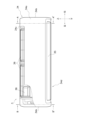
- FIG. 2 is a front view of the usage unit 3.
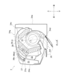
- FIG. 3 is a schematic cross-sectional view of the utilization unit 3 taken along line A-A'.
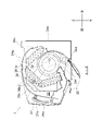
- FIG. 4 is a schematic cross-sectional view of the utilization unit 3 taken along line B-B'.
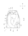
- FIG. 5 is a schematic cross-sectional view taken along line A-A' of the utilization unit 3 with the second filter 37 at the second position.
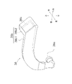
- 6 is a perspective view of the air supply duct 38.
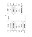
- FIG. FIG. 7 is a control block diagram of the control section 9. As shown in FIG.
- FIG. 1 is a schematic configuration diagram of an air conditioner 1 including a usage unit 3 according to one embodiment.
- the air conditioner 1 air-conditions a room (not shown) such as a building, which is a target space, by a vapor compression refrigerant cycle.
- the air conditioner 1 mainly includes a heat source unit 2, a utilization unit 3, a humidification unit 4, a liquid refrigerant communication pipe 5, a gas refrigerant communication pipe 6, an air supply hose 7, a controller 9, and a remote controller 8. and have
- the liquid refrigerant communication pipe 5 and the gas refrigerant communication pipe 6 connect the heat source unit 2 and the utilization unit 3 .
- the heat source unit 2 , the utilization unit 3 , the liquid refrigerant communication pipe 5 , and the gas refrigerant communication pipe 6 are annularly connected by refrigerant pipes to form a refrigerant circuit 10 .
- the refrigerant circuit 10 has a refrigerant sealed inside.
- the air supply hose 7 connects the humidification unit 4 and the utilization unit 3 .
- the air supply hose 7 is a member that supplies outside air from the humidification unit 4 toward the utilization unit 3 .
- the outside air supplied from the humidification unit 4 to the usage unit 3 includes humidified air obtained by humidifying the outside air.
- control unit 9 controls each device of the air conditioner 1 to perform air conditioning operations such as heating operation, cooling operation, humidification operation, air supply operation, and air cleaning operation.
- the heat source unit 2 is installed outdoors (on the roof of a building, near the exterior wall of the building, etc.).
- the heat source unit 2 mainly has a compressor 21 , a four-way switching valve 23 , a heat source heat exchanger 24 , a heat source expansion valve 25 and a heat source fan 26 .
- the compressor 21 sucks low-pressure refrigerant from the suction side 21a, compresses it to high pressure, and then discharges it from the discharge side 21b.
- a closed-type compressor is used in which a displacement type compression element (not shown) such as a rotary type or a scroll type is rotationally driven by a motor (not shown).
- the number of revolutions of the motor is controlled by the controller 9 via an inverter or the like.
- the capacity of the compressor 21 is controlled by the controller 9 changing the number of revolutions of the motor.
- the four-way switching valve 23 switches the direction of refrigerant flow in the refrigerant circuit 10 .
- the four-way switching valve 23 has a first port P1, a second port P2, a third port P3, and a fourth port P4.
- the four-way switching valve 23 is controlled by the controller 9 to be in the first state (the state indicated by the dashed line in FIG. 1) in which the first port P1 and the fourth port P4 communicate with each other and the second port P2 and the third port P3 communicate with each other. ) and a second state (shown by solid lines in FIG. 1) in which the first port P1 and the second port P2 communicate with each other and the third port P3 and the fourth port P4 communicate with each other.
- the first port P1 is connected to the discharge side 21b of the compressor 21.
- the second port P2 is connected to the gas side of the heat source heat exchanger 24 .
- the third port P3 is connected to the suction side 21a of the compressor 21 .
- the fourth port P4 is connected to the gas refrigerant communication pipe 6 .
- the heat source heat exchanger 24 is a heat exchanger that exchanges heat between the refrigerant and outdoor air in the refrigerant circuit 10 .
- One end of the heat source heat exchanger 24 is connected to the heat source expansion valve 25 .
- the other end of the heat source heat exchanger 24 is connected to the second port P2 of the four-way switching valve 23 .
- the heat source expansion valve 25 is an expansion mechanism that reduces the pressure of the refrigerant in the refrigerant circuit 10 .
- the heat source expansion valve 25 is provided between the liquid refrigerant communication pipe 5 and the liquid side of the heat source heat exchanger 24 .
- the heat source expansion valve 25 is an electric expansion valve whose degree of opening can be controlled. The degree of opening of the heat source expansion valve 25 is controlled by the controller 9 .
- the heat source fan 26 generates airflow and supplies outdoor air to the heat source heat exchanger 24 .
- the heat source fan 26 supplies the outdoor air to the heat source heat exchanger 24, thereby promoting heat exchange between the refrigerant in the heat source heat exchanger 24 and the outdoor air.
- the heat source fan 26 is rotationally driven by a heat source fan motor 26a.
- the air volume of the heat source fan 26 is controlled by the controller 9 changing the rotation speed of the heat source fan motor 26a.
- the usage unit 3 is a wall-mounted indoor air conditioner that is installed on the wall in the room that is the target space.
- the utilization unit 3 mainly includes a utilization heat exchanger 31, a utilization fan 32, a dust detection sensor 33, a casing 34, a flap 35, a first filter 36, a second filter 37, and an air supply duct 38.
- FIG. 2 is a front view of the usage unit 3.
- FIG. 3 is a schematic cross-sectional view of the utilization unit 3 taken along line AA'.
- FIG. 4 is a schematic cross-sectional view of the user unit 3 taken along line BB'.
- part of the casing 34 and the second filter 37 are shown transparently.
- 3 and 4 show a state in which the second filter 37 is at a first position, which will be described later.
- the directions of up, down, front, rear, left and right used in the following description follow the directions indicated by the arrows in FIGS.
- the utilization heat exchanger 31 exchanges heat between the refrigerant and the indoor air in the refrigerant circuit 10 .
- One end of the utilization heat exchanger 31 is connected to the liquid refrigerant communication pipe 5 .
- the other end of the utilization heat exchanger 31 is connected to the gas refrigerant communication pipe 6 .
- the utilization heat exchanger 31 is, for example, but not limited to, a cross-fin type fin-and-tube heat exchanger composed of heat transfer tubes and heat transfer fins.
- the utilization heat exchanger 31 is arranged in the air flow path generated by the utilization fan 32 . Specifically, as shown in FIG. 2, it is arranged so as to cover the front and top of the utilization heat exchanger 31 .
- the utilization fan 32 is a blower that generates an airflow.
- the indoor air passes through the utilization heat exchanger 31 by the utilization fan 32 generating an airflow. Passing the indoor air through the heat utilization exchanger 31 promotes heat exchange between the refrigerant in the heat utilization exchanger 31 and the outdoor air.
- the utilization fan 32 is a cross-flow fan in which the rotation axis O is arranged along the left-right direction.
- the utilization fan 32 is rotationally driven by a utilization fan motor 32a.
- the air volume of the utilization fan 32 is controlled by the controller 9 by changing the rotational speed of the utilization fan motor 32a.
- the utilization fan 32 is an example of a fan.
- the dust detection sensor 33 detects the presence or absence of dust contained in the indoor air.
- the dust detection sensor 33 is provided inside the casing 34 .
- the casing 34 has a substantially rectangular parallelepiped shape elongated in the left-right direction, including a front surface 34a, a side surface 34b, a top surface 34c, a bottom surface 34d, and a rear surface 34e.
- the utilization heat exchanger 31 , the utilization fan 32 , the first filter 36 , the second filter 37 , and the dust detection sensor 33 are housed inside the casing 34 .
- an outlet 34f is formed from which the air that has undergone heat exchange with the refrigerant in the heat utilization exchanger 31 blows out.
- the utilization fan 32 When the utilization fan 32 generates an airflow, the refrigerant that has exchanged heat with the refrigerant in the utilization heat exchanger 31 is blown out into the room through the outlet 34f.
- the top surface 34c is formed with a suction port 34g for letting indoor air flow into the casing 34. As shown in FIG. The indoor air flows into the casing 34 through the suction port 34g by the utilization fan 32 generating an airflow.
- the flap 35 is a substantially plate-shaped member for adjusting the flow rate and/or direction of the air blown out from the blowout port 34f of the casing 34. As shown in FIG. The flap 35 is attached to the casing 34 so as to be rotatable within a predetermined angular range around a rotation axis extending in the left-right direction so as to cover the blowout port 34f. The flap 35 is rotationally driven by a motor (not shown).
- the first filter 36 is a filter through which the airflow generated by the utilization fan 32 passes. More specifically, the first filter 36 is a filter through which air flowing into the casing 34 through the suction port 34g passes. The first filter 36 is provided above the utilization heat exchanger 31 .
- the second filter 37 is a filter that has a higher dust collection capability than the first filter 36 .
- the second filter 37 is also a filter through which the airflow generated by the utilization fan 32 passes. More specifically, the second filter 37 is a filter through which at least part of the airflow flowing into the casing 34 through the suction port 34g passes before passing through the first filter 36 .
- the second filter 37 is arranged upstream of the first filter 36 in the airflow inside the casing 34 so as to partially cover the first filter 36 .
- the second filter 37 is preferably of a pleated type or a non-woven fabric type, which has a high dust collection capability.
- FIG. 5 is a schematic cross-sectional view taken along line A-A' of the utilization unit 3 with the second filter 37 at the second position.
- the air conditioner 1 has a moving device 37a for moving the second filter 37 between the first position and the second position between the front edge of the first filter 36 and the front surface 34a of the casing 34. provided in the first space S1.
- the moving device 37a has a pinion and a motor (not shown).
- the pinion is rotationally driven by a motor.
- the pinion is meshed with a rack formed on the second filter 37 .
- the second filter 37 moves between the first position and the second position as the pinion rotates.
- the motor is rotationally driven by the controller 9 .
- the first position is above the front side of the first filter 36 .
- the second position is inside the housing space S. As shown in FIG. The second filter 37 at the second position is accommodated in the first space S1 without covering the first filter 36, as shown in FIG.
- the air supply duct 38 is a member that supplies outside air supplied from the humidification unit 4 to a predetermined location inside the utilization unit 3 .
- 6 is a perspective view of the air supply duct 38.
- the air supply duct 38 has a suction port 38a, a communicating portion 38b, and an air supply port 38c.
- the suction port 38a is an opening for connecting one end of the air supply hose 7. Outside air supplied from the humidifying unit 4 flows through the air supply hose 7 and into the air supply duct 38 from the suction port 38a.
- the suction port 38a is arranged in the vicinity of the lower side of the back surface 34e, as shown in FIG.
- the communication portion 38b is a pipe that communicates the suction port 38a and the air supply port 38c.
- the communicating portion 38b is mainly composed of a first communicating portion 38b1 and a second communicating portion 38b2.
- the first communication portion 38b1 is a flat pipe that extends forward from the air supply port 38c at the left end inside the casing 34 and then extends upward.
- the second communicating portion 38b2 is a flat pipe extending rightward from the front end of the first communicating portion 38b1 above the heat utilization exchanger 31 .
- the second communication portion 38b2 is formed so as to be located in the second space S2 between the first filter 36 and the heat utilization exchanger 31. As shown in FIG.
- the air supply port 38c is an opening for blowing outside air into the utilization unit 3.
- the air supply port 38c is arranged downstream of the second filter 37 in the air flow, as shown in FIGS. Furthermore, in the air conditioner 1, the air supply port 38c is arranged downstream of the first filter 36 in the air flow. Further, the air supply port 38c is formed so that outside air is blown out toward the downstream side of the airflow.
- the air supply port 38 c is formed so as to face the utilization heat exchanger 31 . Specifically, the air supply port 38c is formed on the surface of the second communication portion 38b2 facing the heat utilization heat exchanger 31. As shown in FIG.
- the air supply port 38c is preferably formed at a position where the shortest distance D (see FIG. 3) to the heat exchanger 31 is 15 mm or less, more preferably 10 mm or less.
- the air supply duct 38 may have a filter for suppressing dust contained in the outside air from blowing out into the usage unit 3 through the air supply port 38c.
- This filter is provided, for example, inside the communicating portion 38b or in the air supply port 38c.
- the humidification unit 4 is a device that supplies outside air to the utilization unit 3 .
- the outside air includes humidified air obtained by humidifying the outside air.
- the humidification unit 4 is installed outdoors (on the roof of a building, near the outer wall surface of the building, etc.) together with the heat source unit 2 .
- the heat source unit 2 and the humidification unit 4 may be integrated.
- the humidification unit 4 mainly has a humidification rotor 41 , a heater 42 , an air supply fan 43 , an adsorption fan 44 , a first path 45 and a second path 46 .
- the humidification rotor 41 is a humidity control rotor that adsorbs moisture in the outside air and releases the adsorbed moisture when heated.
- the humidification rotor 41 has a honeycomb structure and has a substantially disk-shaped outer shape.
- the humidification rotor 63 is manufactured using a material that adsorbs moisture in the air at room temperature and releases moisture when exposed to heated air or the like and the temperature rises.
- the material of the humidification rotor 63 is not limited, it is an adsorbent such as silica gel or zeolite.
- the humidification rotor 41 is provided rotatably in the circumferential direction inside the humidification unit 4, and is rotated by a rotor drive motor 41a.
- the rotor drive motor 41 a is controlled by the controller 9 .
- the heater 42 heats the humidifying rotor 41 .
- the heater 42 is provided in the first path 45 and heats the outside air sent to the humidification rotor 41 through the first path 45 .
- the heated outside air is sent to the humidification rotor 41 .
- the heater 42 is controlled by the controller 9 .
- the air supply fan 43 is an air blower that flows the outside air into the first path 45 and supplies the outside air to the air supply hose 7 .
- the air supply fan 43 is controlled by the controller 9 .
- the adsorption fan 44 is an air blower that causes outside air to flow into the second path 46 .
- the suction fan 44 is controlled by the controller 9 .
- the first path 45 is a ventilation path for supplying outside air that has passed through the humidification rotor 41 to the air supply fan 43 .
- the first path 45 is a path that connects the first intake port 45a, the heater 42, the humidifying section 45b, and the first discharge port 45c in this order. .
- the first intake port 45a is an opening formed in the humidification unit 4. Outside air flows into the first path 45 through the first intake port 45a.
- the humidifying portion 45b is a portion where a predetermined range in the circumferential direction of the humidifying rotor 41 is exposed. The moisture adsorbed by the humidifying rotor 41 is released to the outside air heated by the heater 42 and passing through the humidifying section 45b.
- the first discharge port 45c is connected to the air supply fan 43. Outside air flows into the air supply fan 43 through the first outlet 45c.
- the second path 46 is a ventilation path that causes the humidifying rotor 41 to adsorb moisture contained in the inflowing outside air. Specifically, as shown in FIG. 2, the second path 46 is a path that connects the second intake port 46a, the suction portion 46b, the suction fan 44, and the second discharge port 46c in this order. be.
- the second intake port 46a is an opening formed in the humidification unit 4. Outside air flows into the second path 46 through the second intake port 46a.
- the adsorption portion 46b is a portion where a predetermined range in the circumferential direction of the humidification rotor 41 is exposed.
- the exposed range of the adsorption section 46b is different from the exposed range of the humidifying section 45b. Moisture contained in the outside air that has flowed into the second path 46 is adsorbed by the humidification rotor 41 in the adsorption portion 46b.
- the second discharge port 46c is an opening formed in the humidification unit 4.
- the outside air with moisture adsorbed on the humidifying rotor 41 flows out of the second path 46 through the second outlet 46c.
- the remote controller 8 is used by the user to perform any one of the heating operation, cooling operation, humidifying operation, air supply operation, and air cleaning operation, stop the air conditioner 1, set temperature Ts, etc. It accepts the setting value and transmits the accepted result to the control unit 9 as a control signal.
- the control unit 9 records the received set values in the storage device.
- FIG. 7 is a control block diagram of the control unit 9.
- the control unit 9 mainly includes a compressor 21, a four-way switching valve 23, a heat source expansion valve 25, a heat source fan 26, a utilization fan 32, a moving device 37a, a rotor drive motor 41a, and a heater 42.
- the air supply fan 43, the suction fan 44, and the remote control 8 are connected so as to be able to transmit and receive control signals.
- the controller 9 is also connected to the dust detection sensor 33 so as to be able to receive detection signals.
- control unit 9 controls the operation of the compressor 21, the four-way switching valve 23, the heat source expansion valve 25, the heat source fan 26, and the utilization fan 32, respectively, thereby operating the refrigerant circuit 10. Control.
- the control unit 9 is typically implemented by a computer including a control arithmetic device and a storage device (both not shown).
- the control computing unit is a processor, such as a CPU or GPU.
- the control arithmetic unit reads out the control program stored in the storage device and performs operation control according to this control program. Furthermore, the control arithmetic device can write the arithmetic result to the storage device and read the information stored in the storage device according to the control program.
- FIG. 1 is a schematic diagram, and the control unit 9 includes an outdoor control unit provided inside the heat source unit 2 and an internal control unit inside the usage unit 3, which are connected by a communication line capable of transmitting and receiving control signals. It may be configured by an indoor control unit provided.
- control unit 9 When the control unit 9 receives a control signal from the remote control 8 instructing the execution of the heating operation, it starts the heating operation. During the heating operation, the control unit 9 switches the four-way switching valve 23 to the first state (see broken line in FIG. 1). Further, the control unit 9 sets the heat source expansion valve 25 to the degree of opening corresponding to the set temperature Ts received from the remote controller 8, operates the compressor 21, and drives the utilization fan 32 to rotate. As a result, the heat source heat exchanger 24 functions as a refrigerant evaporator, and the utilization heat exchanger 31 functions as a refrigerant condenser.
- the refrigerant circuit 10 functions as follows.
- the high-pressure refrigerant discharged from the compressor 21 exchanges heat with the indoor air supplied by the utilization fan 32 in the utilization heat exchanger 31 and is condensed.
- the indoor air is heated and discharged indoors as conditioned air.
- the condensed refrigerant passes through the heat source expansion valve 25 and is decompressed, it exchanges heat with the outdoor air supplied by the heat source fan 26 in the heat source heat exchanger 24 and evaporates.
- the refrigerant that has passed through the heat source heat exchanger 24 is sucked into the compressor 21 and compressed.
- the control unit 9 receives a control signal from the remote controller 8 instructing the execution of the cooling operation, it starts the cooling operation.
- the controller 9 switches the four-way selector valve 23 to the second state (see the solid line in FIG. 1).
- the control unit 9 sets the heat source expansion valve 25 to the degree of opening corresponding to the set temperature Ts received from the remote controller 8, operates the compressor 21, and drives the utilization fan 32 to rotate.
- the heat source heat exchanger 24 functions as a refrigerant condenser
- the utilization heat exchanger 31 functions as a refrigerant evaporator.
- the refrigerant circuit 10 functions as follows.
- the high pressure refrigerant discharged from the compressor 21 exchanges heat with the outdoor air supplied by the heat source fan 26 in the heat source heat exchanger 24 and is condensed.
- the indoor air is cooled and discharged indoors as conditioned air.
- the refrigerant that has passed through the heat utilization exchanger 31 is sucked into the compressor 21 and compressed.
- Humidification operation is an air conditioning operation in which conditioned air is humidified using humidified air obtained by humidifying outside air.
- the control unit 9 receives a control signal from the remote control 8 for instructing the execution of the humidification operation, the control unit 9 starts the humidification operation.
- the controller 9 rotates the humidification rotor 41 by the rotor drive motor 41a, causes the air supply fan 43 and the adsorption fan 44 to blow air, causes the heater 42 to heat the outside air flowing through the first path 45, and operates the utilization fan. 32 is rotationally driven. While the humidification operation is being performed, the refrigerant circuit 10 can perform the heating operation or the cooling operation.
- the humidification unit 4 functions as follows. As the suction fan 44 rotates, outside air flows into the second path 46 through the second inlet 46a. The outside air that has flowed into the second path 46 passes through a predetermined range of the rotating humidifying rotor 41 in the adsorption portion 46b. Moisture contained in the outside air is adsorbed by the humidifying rotor 41 as the outside air passes through the humidifying rotor 41 . The outside air with moisture adsorbed on the humidifying rotor 41 is discharged to the outside of the humidifying unit 4 through the second outlet 46c.
- outside air flows into the first path 45 from the first intake port 45a.
- the outside air that has flowed into the first path 45 is heated by the heater 42 and then passes through a predetermined range of the rotating humidifying rotor 41 in the humidifying section 45b.
- the heated outside air passes through the humidification rotor 41 , the moisture adsorbed in the adsorption portion 46 b is released from the heated humidification rotor 41 .
- the outside air that has passed through the humidification rotor 41 is humidified to become humidified air, which flows into the air supply fan 43 via the first discharge port 45c.
- the humidified air that has flowed into the air supply fan 43 passes through the air supply hose 7 and flows into the air supply duct 38 of the utilization unit 3, and then, as indicated by the hatched arrows in FIGS. Outside air is blown out from the port 38c.
- the utilization fan 32 is rotationally driven to generate an airflow while the humidified air is blown out as outside air from the air supply port 38c. Therefore, the humidified air blown out from the air supply port 38 c is integrated with the airflow passing through the heat utilization heat exchanger 31 . As a result, humidified conditioned air is blown out from the utilization unit 3 .
- the air supply operation is an air conditioning operation in which outside air is supplied to the target space without being humidified.
- the control unit 9 starts the air supply operation when it receives a control signal from the remote controller 8 for instructing the execution of the air supply operation.
- the controller 9 causes the air supply fan 43 to blow air, and drives the utilization fan 32 to rotate.
- the controller 9 stops the humidification rotor 41 by the rotor drive motor 41a, and stops the adsorption fan 44 and the heater 42.
- the control part 9 may rotate the humidification rotor 41 at low speed by the rotor drive motor 41a. While the air supply operation is being performed, the refrigerant circuit 10 can perform heating operation or cooling operation.
- the humidification unit 4 functions as follows. As the air supply fan 43 rotates, outside air flows into the first path 45 through the first intake port 45a. The outside air that has flowed into the first path 45 passes through a predetermined range of the humidification rotor 41 without being heated by the heater 42 . At this time, since the outside air is not heated, moisture is not released to the outside air passing through the adsorption portion 46b, and humidified air is not generated. The outside air that has passed through the humidification rotor 41 flows into the air supply fan 43 via the first discharge port 45c.
- the outside air that has flowed into the air supply fan 43 flows through the air supply hose 7 into the air supply duct 38 of the utilization unit 3, and then flows through the air supply port as indicated by the hatched arrows in FIGS. It blows out from 38c.
- the utilization fan 32 is rotationally driven to generate an airflow while the outside air is blown out from the air supply port 38c. For this reason, the outside air blown out from the air supply port 38c flows into the casing 34 from the suction port 34g and becomes integrated with the airflow passing through the heat utilization heat exchanger 31 . As a result, outside air and conditioned air are blown out together from the utilization unit 3 .
- the air cleaning operation is an air conditioning operation in which airflow is allowed to pass through the second filter 37 to collect dust in the air.
- the control unit 9 starts the air cleaning operation when it receives a control signal from the remote control 8 to instruct the execution of the air cleaning operation.
- the controller 9 moves the second filter 37 to the first position and drives the utilization fan 32 to rotate.
- the control unit 9 may automatically start executing the air cleaning operation based on the dust detection result by the dust detection sensor 33b.
- the control unit 9 may perform the air cleaning operation simultaneously with the heating operation, the cooling operation, the humidification operation, or the air supply operation.
- the utilization unit 3 which is an indoor air conditioner, includes a utilization fan 32 , a first filter 36 , a second filter 37 , and an air supply duct 38 .
- the utilization fan 32 generates an airflow.
- the first filter 36 is a filter through which the airflow generated by the utilization fan 32 passes.
- the second filter 37 is a filter through which the airflow generated by the utilization fan 32 passes and has a higher dust collection capability than the first filter 36 .
- the air supply duct 38 supplies humidified air obtained by humidifying outside air to the airflow generated by the utilization fan 32 .
- the air supply duct 38 has an air supply port 38c for blowing out humidified air.
- the air supply port 38c is arranged downstream of the second filter 37 in the airflow.
- the air supply port 38c is formed such that humidified air is blown out toward the downstream side of the airflow.
- the utilization fan 32 further includes a utilization heat exchanger 31 .
- the air supply port 38 c is formed so as to face the utilization heat exchanger 31 .
- the shortest distance D between the air supply port 38c and the utilization heat exchanger 31 is 15 mm or less.
- the second filter 37 moves between a first position covering part of the first filter 36 and a second position not covering the first filter.
- the second filter 37 can be moved between two positions as needed to change the distance from the air supply port 38c. Therefore, according to the utilization unit 3, the deterioration of the air cleaning ability due to the humidification operation is effectively suppressed.
- the air supply port 38c of the air supply duct 38 is arranged on the upstream side of the air flow relative to the heat utilization heat exchanger 31, and the outside air or humidified air reaches the rotation axis O of the utilization fan 32. It is formed so as to be blown out along the stretching direction.
- the outside air or humidified air blown out from the air supply port 38c spreads in the direction in which the rotation axis O extends, becoming integrated with the airflow, and can pass through the heat exchanger 31 for utilization. Therefore, according to the utilization unit 3 of the air conditioner 1 according to Modification A, it is possible to effectively humidify the conditioned air while suppressing a decrease in the air cleaning performance due to the humidification operation.
- the second filter 37 may be in the second position while humidified air is being supplied from the air supply duct 38 .
- the controller 9 may move the second filter 37 to the second position during the humidification operation.
- the distance between the air supply port 38c and the second filter 37 is secured while the air is blown out from the air supply port 38c, so that the passage of the humidified air through the second filter 37 is effectively suppressed. . Therefore, according to the utilization unit 3 of the air conditioner 1 according to Modification B, it is possible to effectively suppress a decrease in the air cleaning performance due to the humidification operation.
- the controller 9 does not have to supply humidified air from the air supply duct 38 while the second filter 37 is at the second position. Specifically, when the air cleaning operation is being performed, the control unit 9 does not have to perform the humidification operation even if there is an execution instruction.
- the utilization unit 3 of the air conditioner 1 according to the modified example C it is possible to effectively suppress the deterioration of the air cleaning ability caused by the humidification operation.
- the second filter 37 is moved between the first position and the second position by the moving device 37a. It may be moved manually.
Abstract
Proposed is an indoor air conditioner that can suppress the decrease in air cleaning capacity caused by humidified air. This air-conditioning indoor unit comprises a fan, a first filter, a second filter, and an air supply duct. The indoor air conditioner generates airflow. The first filter allows airflow to pass through. The second filter allows airflow to pass through and has a higher dust collection capacity than the first filter. The air supply duct supplies humidified air, which is obtained by humidifying outside air, to the airflow. The air supply duct has an air supply port for blowing out humidified air. The air supply port is disposed downstream of the second filter in the air flow direction.
Description
空調室内機に関する。
Regarding air conditioning indoor units.
特許文献1(国際公開第2018/230128号)は、エアフィルタと、空気清浄フィルタとを備えた空調室内機を開示している。エアフィルタは、比較的大きな塵埃を捕獲することを目的としたフィルタである。空気清浄フィルタは、エアフィルタより通風抵抗が大きく、エアフィルタを通過するような微粒子を捕獲することを目的としたフィルタである。特許文献1の空調室内機は、塵埃検知センサが空気中に含まれる塵埃を検知すると、移動装置が空気清浄フィルタをエアフィルタの一部を覆う位置に移動させる。これにより、特許文献1の空調室内機は、空気清浄フィルタが空気中の塵埃を集塵する空気清浄運転を実行できる。
Patent Document 1 (International Publication No. 2018/230128) discloses an air conditioning indoor unit that includes an air filter and an air cleaning filter. An air filter is a filter intended to capture relatively large dust particles. An air purifying filter is a filter that has a higher airflow resistance than an air filter and is intended to capture fine particles that pass through the air filter. In the air conditioner indoor unit of Patent Document 1, when the dust detection sensor detects dust contained in the air, the moving device moves the air cleaning filter to a position covering part of the air filter. As a result, the air conditioning indoor unit of Patent Document 1 can perform an air cleaning operation in which the air cleaning filter collects dust in the air.
加湿ユニットが搭載された空気調和装置が知られている。加湿ユニットは、外気を加湿した加湿空気を生成する。空気調和装置は、加湿空気により生成された加湿空気により調和空気を加湿する。しかし、この技術を特許文献1の空調室内機に適用した場合、加湿空気に含まれる水分が付着したり、付着した水分に空気中の塵埃が付着したりすることで空気清浄フィルタに目詰まりが生じ、空調室内機の空気清浄能力が低下する。
An air conditioner equipped with a humidification unit is known. The humidification unit generates humidified air by humidifying outside air. The air conditioner humidifies the conditioned air with humidified air generated from the humidified air. However, when this technology is applied to the air conditioner indoor unit of Patent Document 1, the air purifying filter is clogged due to the adhesion of moisture contained in the humidified air and the adhesion of dust in the air to the attached moisture. As a result, the air cleaning capacity of the indoor unit of the air conditioner decreases.
本開示は、加湿空気に起因する空気洗浄能力の低下を抑制できる室内空調機を提案する。
The present disclosure proposes an indoor air conditioner capable of suppressing deterioration in air cleaning performance caused by humidified air.
第1観点の空調室内機は、ファンと、第1フィルタと、第2フィルタと、給気ダクトとを備える。ファンは、気流を生成する。第1フィルタは、ファンが生成した気流が通過するフィルタである。第2フィルタは、ファンが生成した気流が通過し、第1フィルタよりも塵埃捕集能力が高いフィルタである。給気ダクトは、外気が加湿された加湿空気をファンが生成した気流に供給する。給気ダクトは、加湿空気を吹き出す給気口を有する。給気口は、第2フィルタよりも気流の下流側に配置される。
The air conditioning indoor unit of the first aspect includes a fan, a first filter, a second filter, and an air supply duct. A fan generates an airflow. The first filter is a filter through which the airflow generated by the fan passes. The second filter is a filter through which the airflow generated by the fan passes and has a higher dust collection capability than the first filter. The air supply duct supplies humidified air, which is obtained by humidifying outside air, to the airflow generated by the fan. The air supply duct has an air supply opening for blowing out humidified air. The air supply port is arranged downstream of the second filter in the airflow.
これにより、給気口から吹き出される加湿空気が気流の上流側に位置する第2フィルタを通過することが抑制される。したがって、本室内空調機によれば、加湿運転に起因する空気洗浄能力の低下が抑制される。
This suppresses the humidified air blown out from the air supply port from passing through the second filter located upstream of the airflow. Therefore, according to the present indoor air conditioner, a decrease in air cleaning performance due to the humidification operation is suppressed.
第2観点の空調室内機は、第1観点の空調室内機であって、給気口は、加湿空気が気流の下流側に向けて吹き出されるように形成される。
The air conditioning indoor unit of the second aspect is the air conditioning indoor unit of the first aspect, and the air supply port is formed so that the humidified air is blown out toward the downstream side of the airflow.
これにより、給気口から吹き出される加湿空気が気流の上流側に位置する第2フィルタを通過することが効果的に抑制される。したがって、本室内空調機によれば、加湿運転に起因する空気洗浄能力の低下が効果的に抑制される。
This effectively suppresses the humidified air blown out from the air supply port from passing through the second filter located upstream of the airflow. Therefore, according to the present indoor air conditioner, the deterioration of the air cleaning performance due to the humidification operation is effectively suppressed.
第3観点の空調室内機は、第1観点又は第2観点の空調室内機であって、熱交換器をさらに備える。給気口は、熱交換器に対向するように形成される。給気口と熱交換器との最短距離は、15mm以下である。
The air conditioning indoor unit of the third aspect is the air conditioning indoor unit of the first aspect or the second aspect, and further includes a heat exchanger. The air supply port is formed so as to face the heat exchanger. The shortest distance between the air supply port and the heat exchanger is 15 mm or less.
これにより、給気口から吹き出される加湿空気が熱交換器を通過しやすくなるため、第2フィルタを通過することが効果的に抑制される。したがって、本室内空調機によれば、加湿運転に起因する空気洗浄能力の低下が効果的に抑制される。
This makes it easier for the humidified air blown out from the air supply port to pass through the heat exchanger, effectively suppressing it from passing through the second filter. Therefore, according to the present indoor air conditioner, the deterioration of the air cleaning performance due to the humidification operation is effectively suppressed.
第4観点の空調室内機は、第1観点の空調室内機であって、ファンよりも気流の上流側に配置された熱交換器をさらに備える。ファンは、クロスフローファンである。給気口は、熱交換器よりも気流の上流側に配置され、加湿空気がクロスフローファンの回転軸の延伸方向に沿って吹き出されるように形成される。
The air conditioning indoor unit of the fourth aspect is the air conditioning indoor unit of the first aspect, further comprising a heat exchanger arranged upstream of the airflow relative to the fan. The fan is a cross-flow fan. The air supply port is arranged on the upstream side of the airflow relative to the heat exchanger, and is formed so that the humidified air is blown out along the extending direction of the rotating shaft of the cross-flow fan.
これにより、給気口から吹き出される加湿空気は、回転軸の延伸方向に拡がりながら気流と一体となり熱交換器を通過することができる。したがって、本室内空調機によれば、加湿運転に起因する空気洗浄能力の低下を抑制しながら、調和空気を効果的に加湿することができる。
As a result, the humidified air blown out from the air supply port spreads in the direction of extension of the rotating shaft and is integrated with the air flow to pass through the heat exchanger. Therefore, according to the present indoor air conditioner, it is possible to effectively humidify the conditioned air while suppressing a decrease in the air cleaning performance due to the humidification operation.
第5観点の空調室内機は、第1観点から第4観点のいずれかの空調室内機であって、第2フィルタは、第1フィルタの一部を覆う第1位置と、第1フィルタを覆わない第2位置との間で移動する。
An air conditioning indoor unit according to a fifth aspect is the air conditioning indoor unit according to any one of the first aspect to the fourth aspect, wherein the second filter covers a portion of the first filter at a first position and covers the first filter. No second position.
これにより、第2フィルタは、必要に応じて2つの位置の間で移動して、給気口からの距離を変えることができる。したがって、本室内空調機によれば、加湿運転に起因する空気洗浄能力の低下が効果的に抑制される。
This allows the second filter to move between two positions as needed to change the distance from the air inlet. Therefore, according to the present indoor air conditioner, the deterioration of the air cleaning performance due to the humidification operation is effectively suppressed.
第6観点の空調室内機は、第5観点の空調室内機であって、第2フィルタは、給気ダクトから加湿空気の供給が行われている間、第2位置にある。
The air conditioning indoor unit of the sixth aspect is the air conditioning indoor unit of the fifth aspect, and the second filter is at the second position while humidified air is being supplied from the air supply duct.
これにより、給気口から吹き出される間、給気口と、第2フィルタとの距離が確保されるため、加湿空気が第2フィルタを通過することが効果的に抑制される。このため、本室内空調機によれば、加湿運転に起因する空気洗浄能力の低下を効果的に抑制できる。
As a result, the distance between the air supply port and the second filter is secured while the humidified air is blown out from the air supply port, so that the passage of the humidified air through the second filter is effectively suppressed. Therefore, according to the present indoor air conditioner, it is possible to effectively suppress the deterioration of the air cleaning performance caused by the humidification operation.
第7観点の空調室内機は、第5観点の空調室内機であって、第2フィルタが第2位置にある間、給気ダクトから加湿空気の供給が行われない。
The air conditioning indoor unit of the seventh aspect is the air conditioning indoor unit of the fifth aspect, in which no humidified air is supplied from the air supply duct while the second filter is in the second position.
これにより、給気口と、第2フィルタとの距離が近い間は、給気口から加湿空気が吹き出されないため、加湿空気が第2フィルタを通過することが効果的に抑制される。このため、本室内空調機によれば、加湿運転に起因する空気洗浄能力の低下を効果的に抑制できる。
As a result, while the distance between the air supply port and the second filter is short, the humidified air is not blown out from the air supply port, so the passage of the humidified air through the second filter is effectively suppressed. Therefore, according to the present indoor air conditioner, it is possible to effectively suppress the deterioration of the air cleaning performance caused by the humidification operation.
(1)全体構成
図1は、一実施形態に係る利用ユニット3を含む空気調和装置1の概略構成図である。空気調和装置1は、蒸気圧縮式の冷媒サイクルによって、対象空間である建物等の室内(図示省略)の空調を行う。空気調和装置1は、主として、熱源ユニット2と、利用ユニット3と、加湿ユニット4と、液冷媒連絡管5と、ガス冷媒連絡管6と、給気ホース7と、制御部9と、リモコン8と、を有している。 (1) Overall Configuration FIG. 1 is a schematic configuration diagram of an air conditioner 1 including ausage unit 3 according to one embodiment. The air conditioner 1 air-conditions a room (not shown) such as a building, which is a target space, by a vapor compression refrigerant cycle. The air conditioner 1 mainly includes a heat source unit 2, a utilization unit 3, a humidification unit 4, a liquid refrigerant communication pipe 5, a gas refrigerant communication pipe 6, an air supply hose 7, a controller 9, and a remote controller 8. and have
図1は、一実施形態に係る利用ユニット3を含む空気調和装置1の概略構成図である。空気調和装置1は、蒸気圧縮式の冷媒サイクルによって、対象空間である建物等の室内(図示省略)の空調を行う。空気調和装置1は、主として、熱源ユニット2と、利用ユニット3と、加湿ユニット4と、液冷媒連絡管5と、ガス冷媒連絡管6と、給気ホース7と、制御部9と、リモコン8と、を有している。 (1) Overall Configuration FIG. 1 is a schematic configuration diagram of an air conditioner 1 including a
液冷媒連絡管5及びガス冷媒連絡管6は、熱源ユニット2と、利用ユニット3とを接続する。熱源ユニット2と、利用ユニット3と、液冷媒連絡管5と、ガス冷媒連絡管6と、は冷媒配管により環状に接続されて、冷媒回路10を構成する。冷媒回路10は、内部に冷媒が封入されている。給気ホース7は、加湿ユニット4と、利用ユニット3とを接続する。給気ホース7は、加湿ユニット4から利用ユニット3へ向かって外気を供給する部材である。加湿ユニット4から利用ユニット3へ供給される外気には、外気に加湿をした加湿空気が含まれる。
The liquid refrigerant communication pipe 5 and the gas refrigerant communication pipe 6 connect the heat source unit 2 and the utilization unit 3 . The heat source unit 2 , the utilization unit 3 , the liquid refrigerant communication pipe 5 , and the gas refrigerant communication pipe 6 are annularly connected by refrigerant pipes to form a refrigerant circuit 10 . The refrigerant circuit 10 has a refrigerant sealed inside. The air supply hose 7 connects the humidification unit 4 and the utilization unit 3 . The air supply hose 7 is a member that supplies outside air from the humidification unit 4 toward the utilization unit 3 . The outside air supplied from the humidification unit 4 to the usage unit 3 includes humidified air obtained by humidifying the outside air.
詳細は後述するが、制御部9は、空気調和装置1の各機器を制御して、暖房運転、冷房運転、加湿運転、給気運転、及び空気清浄運転等の空調運転を行う。
Although the details will be described later, the control unit 9 controls each device of the air conditioner 1 to perform air conditioning operations such as heating operation, cooling operation, humidification operation, air supply operation, and air cleaning operation.
(2)詳細構成
(2-1)熱源ユニット
熱源ユニット2は、室外(建物の屋上や建物の外壁面近傍等)に設置されている。熱源ユニット2は、主として、圧縮機21と、四路切換弁23と、熱源熱交換器24と、熱源膨張弁25と、熱源ファン26と、を有している。 (2) Detailed Configuration (2-1) Heat Source Unit Theheat source unit 2 is installed outdoors (on the roof of a building, near the exterior wall of the building, etc.). The heat source unit 2 mainly has a compressor 21 , a four-way switching valve 23 , a heat source heat exchanger 24 , a heat source expansion valve 25 and a heat source fan 26 .
(2-1)熱源ユニット
熱源ユニット2は、室外(建物の屋上や建物の外壁面近傍等)に設置されている。熱源ユニット2は、主として、圧縮機21と、四路切換弁23と、熱源熱交換器24と、熱源膨張弁25と、熱源ファン26と、を有している。 (2) Detailed Configuration (2-1) Heat Source Unit The
(2-1-1)圧縮機
圧縮機21は、冷媒回路10において、低圧の冷媒を吸入側21aから吸入して、高圧になるまで圧縮した後、吐出側21bから吐出する。ここでは、圧縮機21として、ロータリ式やスクロール式等の容積式の圧縮要素(図示省略)がモータ(図示省略)によって回転駆動される密閉式構造の圧縮機が使用されている。モータは、インバータ等を介して、制御部9により回転数が制御される。圧縮機21の容量は、制御部9がモータの回転数を変えることにより制御される。 (2-1-1) Compressor In therefrigerant circuit 10, the compressor 21 sucks low-pressure refrigerant from the suction side 21a, compresses it to high pressure, and then discharges it from the discharge side 21b. Here, as the compressor 21, a closed-type compressor is used in which a displacement type compression element (not shown) such as a rotary type or a scroll type is rotationally driven by a motor (not shown). The number of revolutions of the motor is controlled by the controller 9 via an inverter or the like. The capacity of the compressor 21 is controlled by the controller 9 changing the number of revolutions of the motor.
圧縮機21は、冷媒回路10において、低圧の冷媒を吸入側21aから吸入して、高圧になるまで圧縮した後、吐出側21bから吐出する。ここでは、圧縮機21として、ロータリ式やスクロール式等の容積式の圧縮要素(図示省略)がモータ(図示省略)によって回転駆動される密閉式構造の圧縮機が使用されている。モータは、インバータ等を介して、制御部9により回転数が制御される。圧縮機21の容量は、制御部9がモータの回転数を変えることにより制御される。 (2-1-1) Compressor In the
(2-1-2)四路切換弁
四路切換弁23は、冷媒回路10において、冷媒の流れの方向を切り換える。四路切換弁23は、第1ポートP1と、第2ポートP2と、第3ポートP3と、第4ポートP4と、を有する。四路切換弁23は、制御部9により、第1ポートP1と第4ポートP4が互いに連通して第2ポートP2と第3ポートP3が互いに連通する第1状態(図1の破線で示す状態)と、第1ポートP1と第2ポートP2が互いに連通して第3ポートP3と第4ポートP4が互いに連通する第2状態(図1の実線で示す状態)との間で切り換えられる。 (2-1-2) Four-Way Switching Valve The four-way switching valve 23 switches the direction of refrigerant flow in the refrigerant circuit 10 . The four-way switching valve 23 has a first port P1, a second port P2, a third port P3, and a fourth port P4. The four-way switching valve 23 is controlled by the controller 9 to be in the first state (the state indicated by the dashed line in FIG. 1) in which the first port P1 and the fourth port P4 communicate with each other and the second port P2 and the third port P3 communicate with each other. ) and a second state (shown by solid lines in FIG. 1) in which the first port P1 and the second port P2 communicate with each other and the third port P3 and the fourth port P4 communicate with each other.
四路切換弁23は、冷媒回路10において、冷媒の流れの方向を切り換える。四路切換弁23は、第1ポートP1と、第2ポートP2と、第3ポートP3と、第4ポートP4と、を有する。四路切換弁23は、制御部9により、第1ポートP1と第4ポートP4が互いに連通して第2ポートP2と第3ポートP3が互いに連通する第1状態(図1の破線で示す状態)と、第1ポートP1と第2ポートP2が互いに連通して第3ポートP3と第4ポートP4が互いに連通する第2状態(図1の実線で示す状態)との間で切り換えられる。 (2-1-2) Four-Way Switching Valve The four-
第1ポートP1は、圧縮機21の吐出側21bに接続されている。第2ポートP2は、熱源熱交換器24のガス側に接続されている。第3ポートP3は、圧縮機21の吸入側21aに接続されている。第4ポートP4は、ガス冷媒連絡管6に接続されている。
The first port P1 is connected to the discharge side 21b of the compressor 21. The second port P2 is connected to the gas side of the heat source heat exchanger 24 . The third port P3 is connected to the suction side 21a of the compressor 21 . The fourth port P4 is connected to the gas refrigerant communication pipe 6 .
(2-1-3)熱源熱交換器
熱源熱交換器24は、冷媒回路10において、冷媒と室外の空気との熱交換を行う熱交換器である。熱源熱交換器24の一端は、熱源膨張弁25に接続されている。熱源熱交換器24の他端は、四路切換弁23の第2ポートP2に接続されている。 (2-1-3) Heat Source Heat Exchanger The heatsource heat exchanger 24 is a heat exchanger that exchanges heat between the refrigerant and outdoor air in the refrigerant circuit 10 . One end of the heat source heat exchanger 24 is connected to the heat source expansion valve 25 . The other end of the heat source heat exchanger 24 is connected to the second port P2 of the four-way switching valve 23 .
熱源熱交換器24は、冷媒回路10において、冷媒と室外の空気との熱交換を行う熱交換器である。熱源熱交換器24の一端は、熱源膨張弁25に接続されている。熱源熱交換器24の他端は、四路切換弁23の第2ポートP2に接続されている。 (2-1-3) Heat Source Heat Exchanger The heat
(2-1-4)熱源膨張弁
熱源膨張弁25は、冷媒回路10において、冷媒を減圧する膨張機構である。熱源膨張弁25は、液冷媒連絡管5と、熱源熱交換器24の液側との間に設けられる。熱源膨張弁25は、開度制御が可能な電動膨張弁である。熱源膨張弁25の開度は、制御部9により制御される。 (2-1-4) Heat Source Expansion Valve The heatsource expansion valve 25 is an expansion mechanism that reduces the pressure of the refrigerant in the refrigerant circuit 10 . The heat source expansion valve 25 is provided between the liquid refrigerant communication pipe 5 and the liquid side of the heat source heat exchanger 24 . The heat source expansion valve 25 is an electric expansion valve whose degree of opening can be controlled. The degree of opening of the heat source expansion valve 25 is controlled by the controller 9 .
熱源膨張弁25は、冷媒回路10において、冷媒を減圧する膨張機構である。熱源膨張弁25は、液冷媒連絡管5と、熱源熱交換器24の液側との間に設けられる。熱源膨張弁25は、開度制御が可能な電動膨張弁である。熱源膨張弁25の開度は、制御部9により制御される。 (2-1-4) Heat Source Expansion Valve The heat
(2-1-5)熱源ファン
熱源ファン26は、気流を生成し、室外の空気を熱源熱交換器24に供給する。熱源ファン26が室外の空気を熱源熱交換器24に供給することにより、熱源熱交換器24内の冷媒と室外の空気との熱交換が促される。熱源ファン26は、熱源ファンモータ26aによって回転駆動される。熱源ファン26の風量は、制御部9が熱源ファンモータ26aの回転数を変えることにより制御される。 (2-1-5) Heat Source Fan Theheat source fan 26 generates airflow and supplies outdoor air to the heat source heat exchanger 24 . The heat source fan 26 supplies the outdoor air to the heat source heat exchanger 24, thereby promoting heat exchange between the refrigerant in the heat source heat exchanger 24 and the outdoor air. The heat source fan 26 is rotationally driven by a heat source fan motor 26a. The air volume of the heat source fan 26 is controlled by the controller 9 changing the rotation speed of the heat source fan motor 26a.
熱源ファン26は、気流を生成し、室外の空気を熱源熱交換器24に供給する。熱源ファン26が室外の空気を熱源熱交換器24に供給することにより、熱源熱交換器24内の冷媒と室外の空気との熱交換が促される。熱源ファン26は、熱源ファンモータ26aによって回転駆動される。熱源ファン26の風量は、制御部9が熱源ファンモータ26aの回転数を変えることにより制御される。 (2-1-5) Heat Source Fan The
(2-2)利用ユニット
利用ユニット3は、対象空間である室内において壁に掛けて設置される壁掛け型の室内空調機である。利用ユニット3は、主として、利用熱交換器31と、利用ファン32と、塵埃検知センサ33と、ケーシング34と、フラップ35と、第1フィルタ36と、第2フィルタ37と、給気ダクト38とを有している。図2は、利用ユニット3の正面図である。図3は、利用ユニット3をA-A’線で切断した概略断面図である。図4は、利用ユニット3をB-B’線で切断した概略断面図である。図2では、便宜上、ケーシング34の一部及び第2フィルタ37は透過して図示されている。図3及び図4は、第2フィルタ37が後述する第1位置にある状態を示している。以下の説明で用いる、上、下、前、後、左、右の各方向は、図2、図3、図4に矢印で示された方向に従う。 (2-2) Usage Unit Theusage unit 3 is a wall-mounted indoor air conditioner that is installed on the wall in the room that is the target space. The utilization unit 3 mainly includes a utilization heat exchanger 31, a utilization fan 32, a dust detection sensor 33, a casing 34, a flap 35, a first filter 36, a second filter 37, and an air supply duct 38. have. FIG. 2 is a front view of the usage unit 3. FIG. FIG. 3 is a schematic cross-sectional view of the utilization unit 3 taken along line AA'. FIG. 4 is a schematic cross-sectional view of the user unit 3 taken along line BB'. In FIG. 2, for convenience, part of the casing 34 and the second filter 37 are shown transparently. 3 and 4 show a state in which the second filter 37 is at a first position, which will be described later. The directions of up, down, front, rear, left and right used in the following description follow the directions indicated by the arrows in FIGS.
利用ユニット3は、対象空間である室内において壁に掛けて設置される壁掛け型の室内空調機である。利用ユニット3は、主として、利用熱交換器31と、利用ファン32と、塵埃検知センサ33と、ケーシング34と、フラップ35と、第1フィルタ36と、第2フィルタ37と、給気ダクト38とを有している。図2は、利用ユニット3の正面図である。図3は、利用ユニット3をA-A’線で切断した概略断面図である。図4は、利用ユニット3をB-B’線で切断した概略断面図である。図2では、便宜上、ケーシング34の一部及び第2フィルタ37は透過して図示されている。図3及び図4は、第2フィルタ37が後述する第1位置にある状態を示している。以下の説明で用いる、上、下、前、後、左、右の各方向は、図2、図3、図4に矢印で示された方向に従う。 (2-2) Usage Unit The
(2-2-1)利用熱交換器
利用熱交換器31は、冷媒回路10において、冷媒と室内の空気との熱交換を行う。利用熱交換器31の一端は、液冷媒連絡管5に接続されている。利用熱交換器31の他端は、ガス冷媒連絡管6に接続されている。利用熱交換器31は、限定するものではないが、例えば、伝熱管と伝熱フィンとにより構成されたクロスフィン式のフィン・アンド・チューブ型熱交換器である。 (2-2-1) Utilization heat exchanger Theutilization heat exchanger 31 exchanges heat between the refrigerant and the indoor air in the refrigerant circuit 10 . One end of the utilization heat exchanger 31 is connected to the liquid refrigerant communication pipe 5 . The other end of the utilization heat exchanger 31 is connected to the gas refrigerant communication pipe 6 . The utilization heat exchanger 31 is, for example, but not limited to, a cross-fin type fin-and-tube heat exchanger composed of heat transfer tubes and heat transfer fins.
利用熱交換器31は、冷媒回路10において、冷媒と室内の空気との熱交換を行う。利用熱交換器31の一端は、液冷媒連絡管5に接続されている。利用熱交換器31の他端は、ガス冷媒連絡管6に接続されている。利用熱交換器31は、限定するものではないが、例えば、伝熱管と伝熱フィンとにより構成されたクロスフィン式のフィン・アンド・チューブ型熱交換器である。 (2-2-1) Utilization heat exchanger The
利用熱交換器31は、利用ファン32が生成する気流の流路に配置される。具体的には、図2に示されるように、利用熱交換器31の前方及び上方を覆うように配置される。
The utilization heat exchanger 31 is arranged in the air flow path generated by the utilization fan 32 . Specifically, as shown in FIG. 2, it is arranged so as to cover the front and top of the utilization heat exchanger 31 .
(2-2-2)利用ファン
利用ファン32は、気流を生成する送風装置である。利用ファン32が気流を生成することで、室内の空気が利用熱交換器31を通過する。室内の空気が利用熱交換器31を通過することにより、利用熱交換器31の冷媒と室外の空気との熱交換が促される。 (2-2-2) Utilization Fan Theutilization fan 32 is a blower that generates an airflow. The indoor air passes through the utilization heat exchanger 31 by the utilization fan 32 generating an airflow. Passing the indoor air through the heat utilization exchanger 31 promotes heat exchange between the refrigerant in the heat utilization exchanger 31 and the outdoor air.
利用ファン32は、気流を生成する送風装置である。利用ファン32が気流を生成することで、室内の空気が利用熱交換器31を通過する。室内の空気が利用熱交換器31を通過することにより、利用熱交換器31の冷媒と室外の空気との熱交換が促される。 (2-2-2) Utilization Fan The
利用ファン32は、回転軸Oが左右方向に沿って配置されたクロスフローファンである。利用ファン32は、利用ファンモータ32aによって回転駆動される。利用ファン32の風量は、制御部9により利用ファンモータ32aの回転数を変えることにより制御される。利用ファン32は、ファンの一例である。
The utilization fan 32 is a cross-flow fan in which the rotation axis O is arranged along the left-right direction. The utilization fan 32 is rotationally driven by a utilization fan motor 32a. The air volume of the utilization fan 32 is controlled by the controller 9 by changing the rotational speed of the utilization fan motor 32a. The utilization fan 32 is an example of a fan.
(2-2-3)塵埃検知センサ
塵埃検知センサ33は、室内の空気に含まれる塵埃の有無を検知する。塵埃検知センサ33は、ケーシング34の内部に設けられる。 (2-2-3) Dust Detection Sensor Thedust detection sensor 33 detects the presence or absence of dust contained in the indoor air. The dust detection sensor 33 is provided inside the casing 34 .
塵埃検知センサ33は、室内の空気に含まれる塵埃の有無を検知する。塵埃検知センサ33は、ケーシング34の内部に設けられる。 (2-2-3) Dust Detection Sensor The
(2-2-4)ケーシング
ケーシング34は、前面34aと、側面34bと、天面34cと、底面34d、背面34eとを含む、左右方向に長い略直方体形状である。利用熱交換器31、利用ファン32、第1フィルタ36、第2フィルタ37、及び塵埃検知センサ33は、ケーシング34の内部に収容される。 (2-2-4) Casing Thecasing 34 has a substantially rectangular parallelepiped shape elongated in the left-right direction, including a front surface 34a, a side surface 34b, a top surface 34c, a bottom surface 34d, and a rear surface 34e. The utilization heat exchanger 31 , the utilization fan 32 , the first filter 36 , the second filter 37 , and the dust detection sensor 33 are housed inside the casing 34 .
ケーシング34は、前面34aと、側面34bと、天面34cと、底面34d、背面34eとを含む、左右方向に長い略直方体形状である。利用熱交換器31、利用ファン32、第1フィルタ36、第2フィルタ37、及び塵埃検知センサ33は、ケーシング34の内部に収容される。 (2-2-4) Casing The
前面34aの下方と、底面34dの前方との間には、利用熱交換器31において冷媒と熱交換を行った空気が吹き出す吹出口34fが形成されている。利用ファン32が気流を生成することで、利用熱交換器31の冷媒と熱交換をした冷媒が、吹出口34fを通って室内へ吹き出される。
Between the lower side of the front surface 34a and the front side of the bottom surface 34d, an outlet 34f is formed from which the air that has undergone heat exchange with the refrigerant in the heat utilization exchanger 31 blows out. When the utilization fan 32 generates an airflow, the refrigerant that has exchanged heat with the refrigerant in the utilization heat exchanger 31 is blown out into the room through the outlet 34f.
天面34cには、室内の空気を、ケーシング34の内部へ流入させるための吸込口34gが形成されている。利用ファン32が気流を生成することで、吸込口34gを通って室内の空気がケーシング34の内部へ流入する。
The top surface 34c is formed with a suction port 34g for letting indoor air flow into the casing 34. As shown in FIG. The indoor air flows into the casing 34 through the suction port 34g by the utilization fan 32 generating an airflow.
(2-2-5)フラップ
フラップ35は、ケーシング34の吹出口34fから吹き出される空気の流量及び/又は方向を調整するための略板状の部材である。フラップ35は、左右方向に伸びる回転軸を中心に所定の角度範囲で回転可能に、吹出口34fを覆うようにケーシング34に取り付けられている。フラップ35は、モータ(図示省略)により回転駆動される。 (2-2-5) Flap Theflap 35 is a substantially plate-shaped member for adjusting the flow rate and/or direction of the air blown out from the blowout port 34f of the casing 34. As shown in FIG. The flap 35 is attached to the casing 34 so as to be rotatable within a predetermined angular range around a rotation axis extending in the left-right direction so as to cover the blowout port 34f. The flap 35 is rotationally driven by a motor (not shown).
フラップ35は、ケーシング34の吹出口34fから吹き出される空気の流量及び/又は方向を調整するための略板状の部材である。フラップ35は、左右方向に伸びる回転軸を中心に所定の角度範囲で回転可能に、吹出口34fを覆うようにケーシング34に取り付けられている。フラップ35は、モータ(図示省略)により回転駆動される。 (2-2-5) Flap The
(2-2-6)第1フィルタ
第1フィルタ36は、利用ファン32が生成する気流が通過するフィルタである。より詳細には、第1フィルタ36は、吸込口34gを通ってケーシング34の内部へ流入する気流が通過するフィルタである。第1フィルタ36は、利用熱交換器31の上方に設けられている。 (2-2-6) First Filter Thefirst filter 36 is a filter through which the airflow generated by the utilization fan 32 passes. More specifically, the first filter 36 is a filter through which air flowing into the casing 34 through the suction port 34g passes. The first filter 36 is provided above the utilization heat exchanger 31 .
第1フィルタ36は、利用ファン32が生成する気流が通過するフィルタである。より詳細には、第1フィルタ36は、吸込口34gを通ってケーシング34の内部へ流入する気流が通過するフィルタである。第1フィルタ36は、利用熱交換器31の上方に設けられている。 (2-2-6) First Filter The
(2-2-7)第2フィルタ
第2フィルタ37は、第1フィルタ36よりも塵埃捕集能力が高いフィルタである。第2フィルタ37も、利用ファン32が生成する気流が通過するフィルタである。より詳細には、第2フィルタ37は、吸込口34gを通ってケーシング34の内部へ流入する気流の少なくとも一部が、第1フィルタ36を通過する前に通過するフィルタである。第2フィルタ37は、ケーシング34の内部において、第1フィルタ36の一部を覆うようにして、第1フィルタ36よりも気流の上流側に配置される。第2フィルタ37は、塵埃捕集能力が高いプリーツ式や不織布式であることが好ましい。 (2-2-7) Second Filter Thesecond filter 37 is a filter that has a higher dust collection capability than the first filter 36 . The second filter 37 is also a filter through which the airflow generated by the utilization fan 32 passes. More specifically, the second filter 37 is a filter through which at least part of the airflow flowing into the casing 34 through the suction port 34g passes before passing through the first filter 36 . The second filter 37 is arranged upstream of the first filter 36 in the airflow inside the casing 34 so as to partially cover the first filter 36 . The second filter 37 is preferably of a pleated type or a non-woven fabric type, which has a high dust collection capability.
第2フィルタ37は、第1フィルタ36よりも塵埃捕集能力が高いフィルタである。第2フィルタ37も、利用ファン32が生成する気流が通過するフィルタである。より詳細には、第2フィルタ37は、吸込口34gを通ってケーシング34の内部へ流入する気流の少なくとも一部が、第1フィルタ36を通過する前に通過するフィルタである。第2フィルタ37は、ケーシング34の内部において、第1フィルタ36の一部を覆うようにして、第1フィルタ36よりも気流の上流側に配置される。第2フィルタ37は、塵埃捕集能力が高いプリーツ式や不織布式であることが好ましい。 (2-2-7) Second Filter The
第2フィルタ37は、第1フィルタ36の一部を覆う第1位置と、第1フィルタ36を覆わない第2位置との間で移動することができる。図5は、第2フィルタ37が第2位置にある状態の利用ユニット3をA-A’線で切断した概略断面図である。
The second filter 37 can move between a first position covering part of the first filter 36 and a second position not covering the first filter 36 . FIG. 5 is a schematic cross-sectional view taken along line A-A' of the utilization unit 3 with the second filter 37 at the second position.
空気調和装置1は、第2フィルタ37を第1位置と第2位置との間で移動させるための移動装置37aを、第1フィルタ36の前方の端縁と、ケーシング34の前面34aとの間に設けられた第1空間S1に備える。移動装置37aは、ピニオンと、モータ(図示省略)とを有する。ピニオンは、モータにより回転駆動される。ピニオンは、第2フィルタ37に形成されたラックと噛み合わされる。第2フィルタ37は、ピニオンが回転することにより第1位置と第2位置との間を移動する。モータは、制御部9により回転駆動される。
The air conditioner 1 has a moving device 37a for moving the second filter 37 between the first position and the second position between the front edge of the first filter 36 and the front surface 34a of the casing 34. provided in the first space S1. The moving device 37a has a pinion and a motor (not shown). The pinion is rotationally driven by a motor. The pinion is meshed with a rack formed on the second filter 37 . The second filter 37 moves between the first position and the second position as the pinion rotates. The motor is rotationally driven by the controller 9 .
空気調和装置1では、第1位置は、第1フィルタ36の前方側の上方である。また、第2位置は、収容空間Sの内部である。第2位置にある第2フィルタ37は、図5に示されるように、第1フィルタ36を覆わない状態で第1空間S1に収容される。
In the air conditioner 1 , the first position is above the front side of the first filter 36 . Also, the second position is inside the housing space S. As shown in FIG. The second filter 37 at the second position is accommodated in the first space S1 without covering the first filter 36, as shown in FIG.
(2-2-8)給気ダクト
給気ダクト38は、加湿ユニット4から供給された外気を、利用ユニット3内部の所定の箇所に供給する部材である。図6は、給気ダクト38の斜視図である。給気ダクト38は、吸込口38aと、連通部38bと、給気口38cとを有する。 (2-2-8) Air Supply Duct Theair supply duct 38 is a member that supplies outside air supplied from the humidification unit 4 to a predetermined location inside the utilization unit 3 . 6 is a perspective view of the air supply duct 38. FIG. The air supply duct 38 has a suction port 38a, a communicating portion 38b, and an air supply port 38c.
給気ダクト38は、加湿ユニット4から供給された外気を、利用ユニット3内部の所定の箇所に供給する部材である。図6は、給気ダクト38の斜視図である。給気ダクト38は、吸込口38aと、連通部38bと、給気口38cとを有する。 (2-2-8) Air Supply Duct The
吸込口38aは、給気ホース7の一端を接続するための開口である。加湿ユニット4から供給される外気は、給気ホース7を通り吸込口38aから給気ダクト38に流入する。吸込口38aは、図4に示されるように、背面34eの下方近傍に配置される。
The suction port 38a is an opening for connecting one end of the air supply hose 7. Outside air supplied from the humidifying unit 4 flows through the air supply hose 7 and into the air supply duct 38 from the suction port 38a. The suction port 38a is arranged in the vicinity of the lower side of the back surface 34e, as shown in FIG.
連通部38bは、吸込口38aと、給気口38cとを連通する配管である。連通部38bは、図4、図6に示されるように、主に、第1連通部38b1と、第2連通部38b2とにより構成される。第1連通部38b1は、ケーシング34内部の左端において、給気口38cから上方に向かって伸びた後、前方に向かって伸びる扁平形状の配管である。第2連通部38b2は、第1連通部38b1の前方側端部から、利用熱交換器31の上方を右側に向かって伸びる扁平形状の配管である。第2連通部38b2は、第1フィルタ36と、利用熱交換器31との間の第2空間S2に位置するように形成される。
The communication portion 38b is a pipe that communicates the suction port 38a and the air supply port 38c. As shown in FIGS. 4 and 6, the communicating portion 38b is mainly composed of a first communicating portion 38b1 and a second communicating portion 38b2. The first communication portion 38b1 is a flat pipe that extends forward from the air supply port 38c at the left end inside the casing 34 and then extends upward. The second communicating portion 38b2 is a flat pipe extending rightward from the front end of the first communicating portion 38b1 above the heat utilization exchanger 31 . The second communication portion 38b2 is formed so as to be located in the second space S2 between the first filter 36 and the heat utilization exchanger 31. As shown in FIG.
給気口38cは、外気を利用ユニット3の内部へ吹き出すための開口である。給気口38cは、図3及び図4に示されるように、第2フィルタ37よりも気流の下流側に配置される。さらに、空気調和装置1では、給気口38cは、第1フィルタ36よりも気流の下流側に配置される。また、給気口38cは、外気が気流の下流側に向けて吹き出されるように形成される。とくに空気調和装置1では、給気口38cは、利用熱交換器31に対向するように形成されている。具体的には、給気口38cは、第2連通部38b2の利用熱交換器31に対向する面に形成される。給気口38cは、利用熱交換器31との最短距離D(図3参照)が15mm以下となる位置に形成されることが好ましく、10mm以下となる位置に形成されることがより好ましい。
The air supply port 38c is an opening for blowing outside air into the utilization unit 3. The air supply port 38c is arranged downstream of the second filter 37 in the air flow, as shown in FIGS. Furthermore, in the air conditioner 1, the air supply port 38c is arranged downstream of the first filter 36 in the air flow. Further, the air supply port 38c is formed so that outside air is blown out toward the downstream side of the airflow. Especially in the air conditioner 1 , the air supply port 38 c is formed so as to face the utilization heat exchanger 31 . Specifically, the air supply port 38c is formed on the surface of the second communication portion 38b2 facing the heat utilization heat exchanger 31. As shown in FIG. The air supply port 38c is preferably formed at a position where the shortest distance D (see FIG. 3) to the heat exchanger 31 is 15 mm or less, more preferably 10 mm or less.
給気ダクト38は、外気に含まれる塵埃が給気口38cを通って利用ユニット3の内部に吹き出されることを抑制するためのフィルタを有していてもよい。このフィルタは、たとえば、連通部38bの内部や給気口38cに設けられる。
The air supply duct 38 may have a filter for suppressing dust contained in the outside air from blowing out into the usage unit 3 through the air supply port 38c. This filter is provided, for example, inside the communicating portion 38b or in the air supply port 38c.
(2-3)加湿ユニット
加湿ユニット4は、外気を利用ユニット3に供給する装置である。外気は、外気に加湿をした加湿空気を含む。加湿ユニット4は、熱源ユニット2とともに、室外(建物の屋上や建物の外壁面近傍等)に設置されている。熱源ユニット2と、加湿ユニット4とは一体化されていてもよい。加湿ユニット4は、主に、加湿ロータ41と、ヒータ42と、給気ファン43と、吸着ファン44と、第1経路45と、第2経路46とを有する。 (2-3) Humidification Unit Thehumidification unit 4 is a device that supplies outside air to the utilization unit 3 . The outside air includes humidified air obtained by humidifying the outside air. The humidification unit 4 is installed outdoors (on the roof of a building, near the outer wall surface of the building, etc.) together with the heat source unit 2 . The heat source unit 2 and the humidification unit 4 may be integrated. The humidification unit 4 mainly has a humidification rotor 41 , a heater 42 , an air supply fan 43 , an adsorption fan 44 , a first path 45 and a second path 46 .
加湿ユニット4は、外気を利用ユニット3に供給する装置である。外気は、外気に加湿をした加湿空気を含む。加湿ユニット4は、熱源ユニット2とともに、室外(建物の屋上や建物の外壁面近傍等)に設置されている。熱源ユニット2と、加湿ユニット4とは一体化されていてもよい。加湿ユニット4は、主に、加湿ロータ41と、ヒータ42と、給気ファン43と、吸着ファン44と、第1経路45と、第2経路46とを有する。 (2-3) Humidification Unit The
(2-3-1)加湿ロータ
加湿ロータ41は、外気中の水分を吸着するとともに、加熱されることで吸着した水分を放出する調湿用ロータである。加湿ロータ41は、ハニカム構造を有し、略円盤状の外形を有している。加湿ロータ63は、常温で空気中の水分を吸着し、加熱された空気等に曝されて温度上昇すると水分を放出する材質を用いて製造される。加湿ロータ63の材質は、限定するものではないが、例えばシリカゲルやゼオライト等の吸着剤である。 (2-3-1) Humidification Rotor Thehumidification rotor 41 is a humidity control rotor that adsorbs moisture in the outside air and releases the adsorbed moisture when heated. The humidification rotor 41 has a honeycomb structure and has a substantially disk-shaped outer shape. The humidification rotor 63 is manufactured using a material that adsorbs moisture in the air at room temperature and releases moisture when exposed to heated air or the like and the temperature rises. Although the material of the humidification rotor 63 is not limited, it is an adsorbent such as silica gel or zeolite.
加湿ロータ41は、外気中の水分を吸着するとともに、加熱されることで吸着した水分を放出する調湿用ロータである。加湿ロータ41は、ハニカム構造を有し、略円盤状の外形を有している。加湿ロータ63は、常温で空気中の水分を吸着し、加熱された空気等に曝されて温度上昇すると水分を放出する材質を用いて製造される。加湿ロータ63の材質は、限定するものではないが、例えばシリカゲルやゼオライト等の吸着剤である。 (2-3-1) Humidification Rotor The
加湿ロータ41は、加湿ユニット4の内部において周方向に回転可能に設けられており、ロータ駆動モータ41aによって回転させられる。ロータ駆動モータ41aは、制御部9により制御される。
The humidification rotor 41 is provided rotatably in the circumferential direction inside the humidification unit 4, and is rotated by a rotor drive motor 41a. The rotor drive motor 41 a is controlled by the controller 9 .
(2-3-2)ヒータ
ヒータ42は、加湿ロータ41を加熱する。具体的には、ヒータ42は、第1経路45に設けられ、第1経路45を通って加湿ロータ41へと送られる外気を加熱する。加熱された外気は、加湿ロータ41へ送られる。ヒータ42は、制御部9により制御される。 (2-3-2) Heater Theheater 42 heats the humidifying rotor 41 . Specifically, the heater 42 is provided in the first path 45 and heats the outside air sent to the humidification rotor 41 through the first path 45 . The heated outside air is sent to the humidification rotor 41 . The heater 42 is controlled by the controller 9 .
ヒータ42は、加湿ロータ41を加熱する。具体的には、ヒータ42は、第1経路45に設けられ、第1経路45を通って加湿ロータ41へと送られる外気を加熱する。加熱された外気は、加湿ロータ41へ送られる。ヒータ42は、制御部9により制御される。 (2-3-2) Heater The
(2-3-3)給気ファン
給気ファン43は、外気を第1経路45に流入させるとともに、外気を給気ホース7に供給する送風装置である。給気ファン43は、制御部9により制御される。 (2-3-3) Air Supply Fan Theair supply fan 43 is an air blower that flows the outside air into the first path 45 and supplies the outside air to the air supply hose 7 . The air supply fan 43 is controlled by the controller 9 .
給気ファン43は、外気を第1経路45に流入させるとともに、外気を給気ホース7に供給する送風装置である。給気ファン43は、制御部9により制御される。 (2-3-3) Air Supply Fan The
(2-3-4)吸着ファン
吸着ファン44は、外気を第2経路46に流入させる送風装置である。吸着ファン44は、制御部9により制御される。 (2-3-4) Adsorption Fan Theadsorption fan 44 is an air blower that causes outside air to flow into the second path 46 . The suction fan 44 is controlled by the controller 9 .
吸着ファン44は、外気を第2経路46に流入させる送風装置である。吸着ファン44は、制御部9により制御される。 (2-3-4) Adsorption Fan The
(2-3-5)第1経路
第1経路45は、加湿ロータ41を通過させた外気を、給気ファン43へ供給する通気経路である。具体的には、第1経路45は、図1に示されるように、第1取込口45aと、ヒータ42と、加湿部45bと、第1排出口45cとをこの順で結ぶ経路である。 (2-3-5) First Path Thefirst path 45 is a ventilation path for supplying outside air that has passed through the humidification rotor 41 to the air supply fan 43 . Specifically, as shown in FIG. 1, the first path 45 is a path that connects the first intake port 45a, the heater 42, the humidifying section 45b, and the first discharge port 45c in this order. .
第1経路45は、加湿ロータ41を通過させた外気を、給気ファン43へ供給する通気経路である。具体的には、第1経路45は、図1に示されるように、第1取込口45aと、ヒータ42と、加湿部45bと、第1排出口45cとをこの順で結ぶ経路である。 (2-3-5) First Path The
第1取込口45aは、加湿ユニット4に形成された開口である。外気は、第1取込口45aを通って第1経路45に流入する。
The first intake port 45a is an opening formed in the humidification unit 4. Outside air flows into the first path 45 through the first intake port 45a.
加湿部45bは、加湿ロータ41の周方向における所定範囲が露出する部分である。加湿ロータ41に吸着された水分は、加湿部45bを通過する、ヒータ42で加熱された外気に放出される。
The humidifying portion 45b is a portion where a predetermined range in the circumferential direction of the humidifying rotor 41 is exposed. The moisture adsorbed by the humidifying rotor 41 is released to the outside air heated by the heater 42 and passing through the humidifying section 45b.
第1排出口45cは、給気ファン43に接続されている。外気は、第1排出口45cを通って給気ファン43に流入する。
The first discharge port 45c is connected to the air supply fan 43. Outside air flows into the air supply fan 43 through the first outlet 45c.
(2-3-6)第2経路
第2経路46は、流入した外気に含まれる水分を加湿ロータ41に吸着させる通気経路である。具体的には、第2経路46は、図2に示されるように、第2取込口46aと、吸着部46bと、吸着ファン44と、第2排出口46cとをこの順で結ぶ経路である。 (2-3-6) Second Path Thesecond path 46 is a ventilation path that causes the humidifying rotor 41 to adsorb moisture contained in the inflowing outside air. Specifically, as shown in FIG. 2, the second path 46 is a path that connects the second intake port 46a, the suction portion 46b, the suction fan 44, and the second discharge port 46c in this order. be.
第2経路46は、流入した外気に含まれる水分を加湿ロータ41に吸着させる通気経路である。具体的には、第2経路46は、図2に示されるように、第2取込口46aと、吸着部46bと、吸着ファン44と、第2排出口46cとをこの順で結ぶ経路である。 (2-3-6) Second Path The
第2取込口46aは、加湿ユニット4に形成された開口である。外気は、第2取込口46aを通って第2経路46に流入する。
The second intake port 46a is an opening formed in the humidification unit 4. Outside air flows into the second path 46 through the second intake port 46a.
吸着部46bは、加湿ロータ41の周方向における所定範囲が露出する部分である。吸着部46bにおいて露出する範囲は、加湿部45bにおいて露出する範囲とは異なる。第2経路46に流入した外気に含まれる水分は、吸着部46bにおいて加湿ロータ41に吸着される。
The adsorption portion 46b is a portion where a predetermined range in the circumferential direction of the humidification rotor 41 is exposed. The exposed range of the adsorption section 46b is different from the exposed range of the humidifying section 45b. Moisture contained in the outside air that has flowed into the second path 46 is adsorbed by the humidification rotor 41 in the adsorption portion 46b.
第2排出口46cは、加湿ユニット4に形成された開口である。加湿ロータ41に水分が吸着された外気は、第2排出口46cを通って第2経路46から流出する。
The second discharge port 46c is an opening formed in the humidification unit 4. The outside air with moisture adsorbed on the humidifying rotor 41 flows out of the second path 46 through the second outlet 46c.
(2-4)リモコン
リモコン8は、ユーザーから暖房運転、冷房運転、加湿運転、給気運転、及び空気清浄運転のいずれかの実行指示、空気調和装置1の停止指示、並びに設定温度Ts等の設定値を受け付け、受け付けた結果を制御信号として制御部9に送信する。制御部9は、受信した設定値を記憶装置に記録する。 (2-4) Remote controller Theremote controller 8 is used by the user to perform any one of the heating operation, cooling operation, humidifying operation, air supply operation, and air cleaning operation, stop the air conditioner 1, set temperature Ts, etc. It accepts the setting value and transmits the accepted result to the control unit 9 as a control signal. The control unit 9 records the received set values in the storage device.
リモコン8は、ユーザーから暖房運転、冷房運転、加湿運転、給気運転、及び空気清浄運転のいずれかの実行指示、空気調和装置1の停止指示、並びに設定温度Ts等の設定値を受け付け、受け付けた結果を制御信号として制御部9に送信する。制御部9は、受信した設定値を記憶装置に記録する。 (2-4) Remote controller The
(2-5)制御部
図7は、制御部9の制御ブロック図である。制御部9は、主に、圧縮機21と、四路切換弁23と、熱源膨張弁25と、熱源ファン26と、利用ファン32と、移動装置37aと、ロータ駆動モータ41aと、ヒータ42と、給気ファン43と、吸着ファン44と、リモコン8とのそれぞれに、制御信号を送受信可能に接続されている。また、制御部9は、塵埃検知センサ33に検出信号を受信可能に接続されている。 (2-5) Control Unit FIG. 7 is a control block diagram of thecontrol unit 9. As shown in FIG. The control unit 9 mainly includes a compressor 21, a four-way switching valve 23, a heat source expansion valve 25, a heat source fan 26, a utilization fan 32, a moving device 37a, a rotor drive motor 41a, and a heater 42. , the air supply fan 43, the suction fan 44, and the remote control 8 are connected so as to be able to transmit and receive control signals. The controller 9 is also connected to the dust detection sensor 33 so as to be able to receive detection signals.
図7は、制御部9の制御ブロック図である。制御部9は、主に、圧縮機21と、四路切換弁23と、熱源膨張弁25と、熱源ファン26と、利用ファン32と、移動装置37aと、ロータ駆動モータ41aと、ヒータ42と、給気ファン43と、吸着ファン44と、リモコン8とのそれぞれに、制御信号を送受信可能に接続されている。また、制御部9は、塵埃検知センサ33に検出信号を受信可能に接続されている。 (2-5) Control Unit FIG. 7 is a control block diagram of the
詳細は後述するが、制御部9は、圧縮機21と、四路切換弁23と、熱源膨張弁25と、熱源ファン26と、利用ファン32と、をそれぞれ運転制御することで冷媒回路10を制御する。
Although details will be described later, the control unit 9 controls the operation of the compressor 21, the four-way switching valve 23, the heat source expansion valve 25, the heat source fan 26, and the utilization fan 32, respectively, thereby operating the refrigerant circuit 10. Control.
制御部9は、典型的には、制御演算装置と、記憶装置と(いずれも図示省略)、を備えるコンピュータにより実現される。制御演算装置は、CPU又はGPUといったプロセッサである。制御演算装置は、記憶装置に記憶されている制御プログラムを読み出し、この制御プログラムにしたがって運転制御を行う。さらに、制御演算装置は、制御プログラムしたがって、演算結果を記憶装置に書き込んだり、記憶装置に記憶されている情報を読み出したりすることができる。
The control unit 9 is typically implemented by a computer including a control arithmetic device and a storage device (both not shown). The control computing unit is a processor, such as a CPU or GPU. The control arithmetic unit reads out the control program stored in the storage device and performs operation control according to this control program. Furthermore, the control arithmetic device can write the arithmetic result to the storage device and read the information stored in the storage device according to the control program.
なお、図1は概略図であって、制御部9は、互いに制御信号を送受信可能な通信線で接続された、熱源ユニット2の内部に設けられた室外制御部と、利用ユニット3の内部に設けられた室内制御部とにより構成されてもよい。
Note that FIG. 1 is a schematic diagram, and the control unit 9 includes an outdoor control unit provided inside the heat source unit 2 and an internal control unit inside the usage unit 3, which are connected by a communication line capable of transmitting and receiving control signals. It may be configured by an indoor control unit provided.
(3)空調運転
次に、制御部9が実行する空調運転である、暖房運転、冷房運転、加湿運転、給気運転、及び空気清浄運転について説明する。 (3) Air Conditioning Operation Next, the air conditioning operation performed by thecontrol unit 9, that is, the heating operation, the cooling operation, the humidification operation, the air supply operation, and the air cleaning operation will be described.
次に、制御部9が実行する空調運転である、暖房運転、冷房運転、加湿運転、給気運転、及び空気清浄運転について説明する。 (3) Air Conditioning Operation Next, the air conditioning operation performed by the
(3-1)暖房運転
制御部9は、リモコン8から暖房運転の実行指示についての制御信号を受信すると暖房運転を開始する。暖房運転に際して、制御部9は、四路切換弁23を第1状態へ切り換える(図1の破線参照)。さらに、制御部9は、熱源膨張弁25を、リモコン8から受信した設定温度Tsに対応する開度とし、圧縮機21を運転し、利用ファン32を回転駆動する。これにより、熱源熱交換器24が冷媒の蒸発器として機能し、かつ、利用熱交換器31が冷媒の凝縮器として機能する。 (3-1) Heating operation When thecontrol unit 9 receives a control signal from the remote control 8 instructing the execution of the heating operation, it starts the heating operation. During the heating operation, the control unit 9 switches the four-way switching valve 23 to the first state (see broken line in FIG. 1). Further, the control unit 9 sets the heat source expansion valve 25 to the degree of opening corresponding to the set temperature Ts received from the remote controller 8, operates the compressor 21, and drives the utilization fan 32 to rotate. As a result, the heat source heat exchanger 24 functions as a refrigerant evaporator, and the utilization heat exchanger 31 functions as a refrigerant condenser.
制御部9は、リモコン8から暖房運転の実行指示についての制御信号を受信すると暖房運転を開始する。暖房運転に際して、制御部9は、四路切換弁23を第1状態へ切り換える(図1の破線参照)。さらに、制御部9は、熱源膨張弁25を、リモコン8から受信した設定温度Tsに対応する開度とし、圧縮機21を運転し、利用ファン32を回転駆動する。これにより、熱源熱交換器24が冷媒の蒸発器として機能し、かつ、利用熱交換器31が冷媒の凝縮器として機能する。 (3-1) Heating operation When the
暖房運転の間、冷媒回路10は、次のように機能する。圧縮機21から吐出された高圧の冷媒は、利用熱交換器31で、利用ファン32によって供給される室内の空気と熱交換して凝縮する。これにより、室内の空気は、加熱され、調和空気として室内に排出される。凝縮した冷媒は、熱源膨張弁25を通過して減圧された後、熱源熱交換器24で、熱源ファン26によって供給される室外の空気と熱交換して蒸発する。熱源熱交換器24を通過した冷媒は、圧縮機21へ吸入されて圧縮される。
During heating operation, the refrigerant circuit 10 functions as follows. The high-pressure refrigerant discharged from the compressor 21 exchanges heat with the indoor air supplied by the utilization fan 32 in the utilization heat exchanger 31 and is condensed. As a result, the indoor air is heated and discharged indoors as conditioned air. After the condensed refrigerant passes through the heat source expansion valve 25 and is decompressed, it exchanges heat with the outdoor air supplied by the heat source fan 26 in the heat source heat exchanger 24 and evaporates. The refrigerant that has passed through the heat source heat exchanger 24 is sucked into the compressor 21 and compressed.
(3-2)冷房運転
制御部9は、リモコン8から冷房運転の実行指示についての制御信号を受信すると冷房運転を開始する。冷房運転に際して、制御部9は、四路切換弁23を第2状態へ切り換える(図1の実線参照)。さらに、制御部9は、熱源膨張弁25を、リモコン8から受信した設定温度Tsに対応する開度とし、圧縮機21を運転し、利用ファン32を回転駆動する。これにより、熱源熱交換器24が冷媒の凝縮器として機能し、かつ、利用熱交換器31が冷媒の蒸発器として機能する。 (3-2) Cooling operation When thecontrol unit 9 receives a control signal from the remote controller 8 instructing the execution of the cooling operation, it starts the cooling operation. During the cooling operation, the controller 9 switches the four-way selector valve 23 to the second state (see the solid line in FIG. 1). Further, the control unit 9 sets the heat source expansion valve 25 to the degree of opening corresponding to the set temperature Ts received from the remote controller 8, operates the compressor 21, and drives the utilization fan 32 to rotate. As a result, the heat source heat exchanger 24 functions as a refrigerant condenser, and the utilization heat exchanger 31 functions as a refrigerant evaporator.
制御部9は、リモコン8から冷房運転の実行指示についての制御信号を受信すると冷房運転を開始する。冷房運転に際して、制御部9は、四路切換弁23を第2状態へ切り換える(図1の実線参照)。さらに、制御部9は、熱源膨張弁25を、リモコン8から受信した設定温度Tsに対応する開度とし、圧縮機21を運転し、利用ファン32を回転駆動する。これにより、熱源熱交換器24が冷媒の凝縮器として機能し、かつ、利用熱交換器31が冷媒の蒸発器として機能する。 (3-2) Cooling operation When the
冷房運転の間、冷媒回路10は、次のように機能する。圧縮機21から吐出された高圧の冷媒は、熱源熱交換器24で、熱源ファン26によって供給される室外の空気と熱交換して凝縮する。凝縮した冷媒は、熱源膨張弁25を通過して減圧された後、利用熱交換器31で、利用ファン32によって供給される室内の空気と熱交換して蒸発する。これにより、室内の空気は冷却され、調和空気として室内に排出される。利用熱交換器31を通過した冷媒は、圧縮機21へ吸入されて圧縮される。
During cooling operation, the refrigerant circuit 10 functions as follows. The high pressure refrigerant discharged from the compressor 21 exchanges heat with the outdoor air supplied by the heat source fan 26 in the heat source heat exchanger 24 and is condensed. After the condensed refrigerant passes through the heat source expansion valve 25 and is decompressed, it exchanges heat with the indoor air supplied by the utilization fan 32 in the utilization heat exchanger 31 and evaporates. As a result, the indoor air is cooled and discharged indoors as conditioned air. The refrigerant that has passed through the heat utilization exchanger 31 is sucked into the compressor 21 and compressed.
(3-3)加湿運転
加湿運転は、外気を加湿した加湿空気を用いて調和空気を加湿する空調運転である。制御部9は、リモコン8から加湿運転の実行指示についての制御信号を受信すると加湿運転を開始する。加湿運転に際して、制御部9は、ロータ駆動モータ41aにより加湿ロータ41を回転させ、給気ファン43及び吸着ファン44に送風をさせ、ヒータ42に第1経路45を流れる外気を加熱させ、利用ファン32を回転駆動する。加湿運転が実行されている間、冷媒回路10は、暖房運転又は冷房運転を実行することができる。 (3-3) Humidification operation Humidification operation is an air conditioning operation in which conditioned air is humidified using humidified air obtained by humidifying outside air. When thecontrol unit 9 receives a control signal from the remote control 8 for instructing the execution of the humidification operation, the control unit 9 starts the humidification operation. During the humidification operation, the controller 9 rotates the humidification rotor 41 by the rotor drive motor 41a, causes the air supply fan 43 and the adsorption fan 44 to blow air, causes the heater 42 to heat the outside air flowing through the first path 45, and operates the utilization fan. 32 is rotationally driven. While the humidification operation is being performed, the refrigerant circuit 10 can perform the heating operation or the cooling operation.
加湿運転は、外気を加湿した加湿空気を用いて調和空気を加湿する空調運転である。制御部9は、リモコン8から加湿運転の実行指示についての制御信号を受信すると加湿運転を開始する。加湿運転に際して、制御部9は、ロータ駆動モータ41aにより加湿ロータ41を回転させ、給気ファン43及び吸着ファン44に送風をさせ、ヒータ42に第1経路45を流れる外気を加熱させ、利用ファン32を回転駆動する。加湿運転が実行されている間、冷媒回路10は、暖房運転又は冷房運転を実行することができる。 (3-3) Humidification operation Humidification operation is an air conditioning operation in which conditioned air is humidified using humidified air obtained by humidifying outside air. When the
加湿運転の間、加湿ユニット4は、次のように機能する。吸着ファン44が回転することにより第2取込口46aから第2経路46に外気が流入する。第2経路46に流入した外気は、吸着部46bにおいて、回転する加湿ロータ41の所定範囲を通過する。外気が加湿ロータ41を通過することで、外気に含まれる水分が加湿ロータ41に吸着される。加湿ロータ41に水分が吸着された外気は、第2排出口46cから加湿ユニット4の外部へ排出される。
During humidification operation, the humidification unit 4 functions as follows. As the suction fan 44 rotates, outside air flows into the second path 46 through the second inlet 46a. The outside air that has flowed into the second path 46 passes through a predetermined range of the rotating humidifying rotor 41 in the adsorption portion 46b. Moisture contained in the outside air is adsorbed by the humidifying rotor 41 as the outside air passes through the humidifying rotor 41 . The outside air with moisture adsorbed on the humidifying rotor 41 is discharged to the outside of the humidifying unit 4 through the second outlet 46c.
給気ファン43が回転することにより第1取込口45aから第1経路45に外気が流入する。第1経路45に流入した外気は、ヒータ42で加熱された後、加湿部45bにおいて、回転する加湿ロータ41の所定範囲を通過する。加熱された外気が加湿ロータ41を通過することで、加熱された加湿ロータ41から、吸着部46bにおいて吸着された水分が放出される。この結果、加湿ロータ41を通過した外気は加湿されて加湿空気となり、第1排出口45cを経由して給気ファン43に流入する。給気ファン43に流入した加湿空気は、給気ホース7を通って利用ユニット3の給気ダクト38へ流入した後、図3及び図5にハッチングを付した矢印で示されるように、給気口38cから外気として吹き出される。利用ファン32は、給気口38cから加湿空気が外気として吹き出されている間、回転駆動をして気流を生成している。このため、給気口38cから吹き出された加湿空気は、利用熱交換器31を通過する気流と一体となる。この結果、利用ユニット3からは、加湿された調和空気が吹き出される。
As the air supply fan 43 rotates, outside air flows into the first path 45 from the first intake port 45a. The outside air that has flowed into the first path 45 is heated by the heater 42 and then passes through a predetermined range of the rotating humidifying rotor 41 in the humidifying section 45b. As the heated outside air passes through the humidification rotor 41 , the moisture adsorbed in the adsorption portion 46 b is released from the heated humidification rotor 41 . As a result, the outside air that has passed through the humidification rotor 41 is humidified to become humidified air, which flows into the air supply fan 43 via the first discharge port 45c. The humidified air that has flowed into the air supply fan 43 passes through the air supply hose 7 and flows into the air supply duct 38 of the utilization unit 3, and then, as indicated by the hatched arrows in FIGS. Outside air is blown out from the port 38c. The utilization fan 32 is rotationally driven to generate an airflow while the humidified air is blown out as outside air from the air supply port 38c. Therefore, the humidified air blown out from the air supply port 38 c is integrated with the airflow passing through the heat utilization heat exchanger 31 . As a result, humidified conditioned air is blown out from the utilization unit 3 .
(3-4)給気運転
給気運転は、外気を加湿することなく対象空間に供給する空調運転である。制御部9は、リモコン8から給気運転の実行指示についての制御信号を受信すると給気運転を開始する。給気運転に際して、制御部9は、給気ファン43に送風をさせ、利用ファン32を回転駆動する。他方で、制御部9は、ロータ駆動モータ41aにより加湿ロータ41を停止させ、吸着ファン44及びヒータ42を停止する。なお、制御部9は、ロータ駆動モータ41aにより加湿ロータ41を低速で回転させてもよい。給気運転が実行されている間、冷媒回路10は、暖房運転又は冷房運転を実行することができる。 (3-4) Air supply operation The air supply operation is an air conditioning operation in which outside air is supplied to the target space without being humidified. Thecontrol unit 9 starts the air supply operation when it receives a control signal from the remote controller 8 for instructing the execution of the air supply operation. During the air supply operation, the controller 9 causes the air supply fan 43 to blow air, and drives the utilization fan 32 to rotate. On the other hand, the controller 9 stops the humidification rotor 41 by the rotor drive motor 41a, and stops the adsorption fan 44 and the heater 42. FIG. In addition, the control part 9 may rotate the humidification rotor 41 at low speed by the rotor drive motor 41a. While the air supply operation is being performed, the refrigerant circuit 10 can perform heating operation or cooling operation.
給気運転は、外気を加湿することなく対象空間に供給する空調運転である。制御部9は、リモコン8から給気運転の実行指示についての制御信号を受信すると給気運転を開始する。給気運転に際して、制御部9は、給気ファン43に送風をさせ、利用ファン32を回転駆動する。他方で、制御部9は、ロータ駆動モータ41aにより加湿ロータ41を停止させ、吸着ファン44及びヒータ42を停止する。なお、制御部9は、ロータ駆動モータ41aにより加湿ロータ41を低速で回転させてもよい。給気運転が実行されている間、冷媒回路10は、暖房運転又は冷房運転を実行することができる。 (3-4) Air supply operation The air supply operation is an air conditioning operation in which outside air is supplied to the target space without being humidified. The
給気運転の間、加湿ユニット4は、次のように機能する。給気ファン43が回転することにより第1取込口45aから第1経路45に外気が流入する。第1経路45に流入した外気は、ヒータ42で加熱されることなく加湿ロータ41の所定範囲を通過する。この際、外気が加熱されていないため、吸着部46bを通過する外気に水分が放出されず、加湿空気は生成されない。加湿ロータ41を通過した外気は、第1排出口45cを経由して給気ファン43に流入する。給気ファン43に流入した外気は、給気ホース7を通って利用ユニット3の給気ダクト38へ流入した後、図3及び図5にハッチングを付した矢印で示されるように、給気口38cから吹き出される。利用ファン32は、給気口38cから外気が吹き出されている間、回転駆動をして気流を生成している。このため、給気口38cから吹き出された外気は、吸込口34gからケーシング34に流入して利用熱交換器31を通過する気流と一体となる。この結果、利用ユニット3からは、外気と調和空気とが一体となって吹き出される。
During the air supply operation, the humidification unit 4 functions as follows. As the air supply fan 43 rotates, outside air flows into the first path 45 through the first intake port 45a. The outside air that has flowed into the first path 45 passes through a predetermined range of the humidification rotor 41 without being heated by the heater 42 . At this time, since the outside air is not heated, moisture is not released to the outside air passing through the adsorption portion 46b, and humidified air is not generated. The outside air that has passed through the humidification rotor 41 flows into the air supply fan 43 via the first discharge port 45c. The outside air that has flowed into the air supply fan 43 flows through the air supply hose 7 into the air supply duct 38 of the utilization unit 3, and then flows through the air supply port as indicated by the hatched arrows in FIGS. It blows out from 38c. The utilization fan 32 is rotationally driven to generate an airflow while the outside air is blown out from the air supply port 38c. For this reason, the outside air blown out from the air supply port 38c flows into the casing 34 from the suction port 34g and becomes integrated with the airflow passing through the heat utilization heat exchanger 31 . As a result, outside air and conditioned air are blown out together from the utilization unit 3 .
(3-5)空気清浄運転
空気清浄運転は、第2フィルタ37に気流を通過させることで空気中の塵埃を捕集する空調運転である。制御部9は、リモコン8から空気清浄運転の実行指示についての制御信号を受信すると空気清浄運転を開始する。空気清浄運転に際して、制御部9は、第2フィルタ37を第1位置へ移動し、利用ファン32を回転駆動する。 (3-5) Air Cleaning Operation The air cleaning operation is an air conditioning operation in which airflow is allowed to pass through thesecond filter 37 to collect dust in the air. The control unit 9 starts the air cleaning operation when it receives a control signal from the remote control 8 to instruct the execution of the air cleaning operation. During the air cleaning operation, the controller 9 moves the second filter 37 to the first position and drives the utilization fan 32 to rotate.
空気清浄運転は、第2フィルタ37に気流を通過させることで空気中の塵埃を捕集する空調運転である。制御部9は、リモコン8から空気清浄運転の実行指示についての制御信号を受信すると空気清浄運転を開始する。空気清浄運転に際して、制御部9は、第2フィルタ37を第1位置へ移動し、利用ファン32を回転駆動する。 (3-5) Air Cleaning Operation The air cleaning operation is an air conditioning operation in which airflow is allowed to pass through the
空気清浄運転の間、図3に破線の矢印で示されるように、利用ファン32により生成された気流の少なくとも一部が第2フィルタ37を通過する。言い換えると、吸込口34gから利用ユニット3のケーシング34に流入する気流の少なくとも一部が第2フィルタ37を通過する。この結果、第2フィルタ37において塵埃が捕集され、対象空間の空気が清浄化される。
During the air cleaning operation, at least part of the airflow generated by the utilization fan 32 passes through the second filter 37, as indicated by the dashed arrow in FIG. In other words, at least part of the airflow flowing into the casing 34 of the usage unit 3 from the suction port 34 g passes through the second filter 37 . As a result, dust is collected by the second filter 37, and the air in the target space is purified.
制御部9は、塵埃検知センサ33bによる塵埃検知結果に基づいて、自動的に空気清浄運転の実行を開始してもよい。制御部9は、空気清浄運転を、暖房運転、冷房運転、加湿運転、又は給気運転と同時に実行してもよい。
The control unit 9 may automatically start executing the air cleaning operation based on the dust detection result by the dust detection sensor 33b. The control unit 9 may perform the air cleaning operation simultaneously with the heating operation, the cooling operation, the humidification operation, or the air supply operation.
(4)特徴
(4-1)
室内空調機である利用ユニット3は、利用ファン32と、第1フィルタ36と、第2フィルタ37と、給気ダクト38とを備える。利用ファン32は、気流を生成する。第1フィルタ36は、利用ファン32が生成した気流が通過するフィルタである。第2フィルタ37は、利用ファン32が生成した気流が通過し、第1フィルタ36よりも塵埃捕集能力が高いフィルタである。給気ダクト38は、外気が加湿された加湿空気を利用ファン32が生成した気流に供給する。給気ダクト38は、加湿空気を吹き出す給気口38cを有する。給気口38cは、第2フィルタ37よりも気流の下流側に配置される。 (4) Features (4-1)
Theutilization unit 3 , which is an indoor air conditioner, includes a utilization fan 32 , a first filter 36 , a second filter 37 , and an air supply duct 38 . The utilization fan 32 generates an airflow. The first filter 36 is a filter through which the airflow generated by the utilization fan 32 passes. The second filter 37 is a filter through which the airflow generated by the utilization fan 32 passes and has a higher dust collection capability than the first filter 36 . The air supply duct 38 supplies humidified air obtained by humidifying outside air to the airflow generated by the utilization fan 32 . The air supply duct 38 has an air supply port 38c for blowing out humidified air. The air supply port 38c is arranged downstream of the second filter 37 in the airflow.
(4-1)
室内空調機である利用ユニット3は、利用ファン32と、第1フィルタ36と、第2フィルタ37と、給気ダクト38とを備える。利用ファン32は、気流を生成する。第1フィルタ36は、利用ファン32が生成した気流が通過するフィルタである。第2フィルタ37は、利用ファン32が生成した気流が通過し、第1フィルタ36よりも塵埃捕集能力が高いフィルタである。給気ダクト38は、外気が加湿された加湿空気を利用ファン32が生成した気流に供給する。給気ダクト38は、加湿空気を吹き出す給気口38cを有する。給気口38cは、第2フィルタ37よりも気流の下流側に配置される。 (4) Features (4-1)
The
これにより、給気口38cから吹き出される加湿空気が気流の上流側に位置する第2フィルタ37を通過することが抑制される。したがって、利用ユニット3によれば、加湿運転に起因する空気洗浄能力の低下が抑制される。
This suppresses the humidified air blown out from the air supply port 38c from passing through the second filter 37 located on the upstream side of the airflow. Therefore, according to the utilization unit 3, the deterioration of the air cleaning ability due to the humidification operation is suppressed.
(4-2)
給気口38cは、加湿空気が気流の下流側に向けて吹き出されるように形成される。 (4-2)
Theair supply port 38c is formed such that humidified air is blown out toward the downstream side of the airflow.
給気口38cは、加湿空気が気流の下流側に向けて吹き出されるように形成される。 (4-2)
The
これにより、給気口38cから吹き出される加湿空気が気流の上流側に位置する第2フィルタ37を通過することが効果的に抑制される。したがって、利用ユニット3によれば、加湿運転に起因する空気洗浄能力の低下が効果的に抑制される。
This effectively suppresses the humidified air blown out from the air supply port 38c from passing through the second filter 37 positioned on the upstream side of the airflow. Therefore, according to the utilization unit 3, the deterioration of the air cleaning ability due to the humidification operation is effectively suppressed.
(4-3)
利用ファン32は、利用熱交換器31をさらに備える。給気口38cは、利用熱交換器31に対向するように形成される。給気口38cと利用熱交換器31との最短距離Dは、15mm以下である。 (4-3)
Theutilization fan 32 further includes a utilization heat exchanger 31 . The air supply port 38 c is formed so as to face the utilization heat exchanger 31 . The shortest distance D between the air supply port 38c and the utilization heat exchanger 31 is 15 mm or less.
利用ファン32は、利用熱交換器31をさらに備える。給気口38cは、利用熱交換器31に対向するように形成される。給気口38cと利用熱交換器31との最短距離Dは、15mm以下である。 (4-3)
The
これにより、給気口38cから吹き出される加湿空気が利用熱交換器31を通過しやすくなるため、第2フィルタ37を通過することが効果的に抑制される。したがって、利用ユニット3によれば、加湿運転に起因する空気洗浄能力の低下が効果的に抑制される。
This makes it easier for the humidified air blown out from the air supply port 38c to pass through the heat utilization heat exchanger 31, so that passing through the second filter 37 is effectively suppressed. Therefore, according to the utilization unit 3, the deterioration of the air cleaning ability due to the humidification operation is effectively suppressed.
(4-4)
第2フィルタ37は、第1フィルタ36の一部を覆う第1位置と、第1フィルタを覆わない第2位置との間で移動する。 (4-4)
Thesecond filter 37 moves between a first position covering part of the first filter 36 and a second position not covering the first filter.
第2フィルタ37は、第1フィルタ36の一部を覆う第1位置と、第1フィルタを覆わない第2位置との間で移動する。 (4-4)
The
これにより、第2フィルタ37は、必要に応じて2つの位置の間で移動して、給気口38cからの距離を変えることができる。したがって、利用ユニット3によれば、加湿運転に起因する空気洗浄能力の低下が効果的に抑制される。
Thereby, the second filter 37 can be moved between two positions as needed to change the distance from the air supply port 38c. Therefore, according to the utilization unit 3, the deterioration of the air cleaning ability due to the humidification operation is effectively suppressed.
(5)変形例
(5-1)変形例A
上述の実施形態に係る空気調和装置1では、給気ダクト38の給気口38cは、外気又は加湿空気が気流の下流側に向けて吹き出されるように形成されたが、給気口38c形成される方向はこれに限定されない。 (5) Modification (5-1) Modification A
In the air conditioner 1 according to the above-described embodiment, theair supply port 38c of the air supply duct 38 is formed so that outside air or humidified air is blown out toward the downstream side of the airflow. The direction to be set is not limited to this.
(5-1)変形例A
上述の実施形態に係る空気調和装置1では、給気ダクト38の給気口38cは、外気又は加湿空気が気流の下流側に向けて吹き出されるように形成されたが、給気口38c形成される方向はこれに限定されない。 (5) Modification (5-1) Modification A
In the air conditioner 1 according to the above-described embodiment, the
変形例Aに係る空気調和装置1では、給気ダクト38の給気口38cは、利用熱交換器31よりも気流の上流側に配置され、外気又は加湿空気が利用ファン32の回転軸Oの延伸方向に沿って吹き出されるように形成される。
In the air conditioner 1 according to Modification A, the air supply port 38c of the air supply duct 38 is arranged on the upstream side of the air flow relative to the heat utilization heat exchanger 31, and the outside air or humidified air reaches the rotation axis O of the utilization fan 32. It is formed so as to be blown out along the stretching direction.
これにより、給気口38cから吹き出される外気又は加湿空気は、回転軸Oの延伸方向に拡がりながら気流と一体となり利用熱交換器31を通過することができる。したがって、変形例Aに係る空気調和装置1の利用ユニット3によれば、加湿運転に起因する空気洗浄能力の低下を抑制しながら、調和空気を効果的に加湿することができる。
As a result, the outside air or humidified air blown out from the air supply port 38c spreads in the direction in which the rotation axis O extends, becoming integrated with the airflow, and can pass through the heat exchanger 31 for utilization. Therefore, according to the utilization unit 3 of the air conditioner 1 according to Modification A, it is possible to effectively humidify the conditioned air while suppressing a decrease in the air cleaning performance due to the humidification operation.
(5-2)変形例B
第2フィルタ37は、給気ダクト38から加湿空気の供給が行われている間、第2位置にあってもよい。言い換えると、制御部9は、加湿運転の間、第2フィルタ37を第2位置に移動させてもよい。 (5-2) Modification B
Thesecond filter 37 may be in the second position while humidified air is being supplied from the air supply duct 38 . In other words, the controller 9 may move the second filter 37 to the second position during the humidification operation.
第2フィルタ37は、給気ダクト38から加湿空気の供給が行われている間、第2位置にあってもよい。言い換えると、制御部9は、加湿運転の間、第2フィルタ37を第2位置に移動させてもよい。 (5-2) Modification B
The
これにより、給気口38cから吹き出される間、給気口38cと、第2フィルタ37との距離が確保されるため、加湿空気が第2フィルタ37を通過することが効果的に抑制される。このため、変形例Bに係る空気調和装置1の利用ユニット3によれば、加湿運転に起因する空気洗浄能力の低下を効果的に抑制できる。
As a result, the distance between the air supply port 38c and the second filter 37 is secured while the air is blown out from the air supply port 38c, so that the passage of the humidified air through the second filter 37 is effectively suppressed. . Therefore, according to the utilization unit 3 of the air conditioner 1 according to Modification B, it is possible to effectively suppress a decrease in the air cleaning performance due to the humidification operation.
(5-3)変形例C
制御部9は、第2フィルタ37が第2位置にある間、給気ダクト38から加湿空気の供給が行われなくてもよい。具体的には、制御部9は、空気清浄運転を行っている場合には、実行指示があっても加湿運転を実行しなくてもよい。 (5-3) Modification C
Thecontroller 9 does not have to supply humidified air from the air supply duct 38 while the second filter 37 is at the second position. Specifically, when the air cleaning operation is being performed, the control unit 9 does not have to perform the humidification operation even if there is an execution instruction.
制御部9は、第2フィルタ37が第2位置にある間、給気ダクト38から加湿空気の供給が行われなくてもよい。具体的には、制御部9は、空気清浄運転を行っている場合には、実行指示があっても加湿運転を実行しなくてもよい。 (5-3) Modification C
The
これにより、給気口38cと、第2フィルタ37との距離が近い間は、給気口38cから加湿空気が吹き出されないため、加湿空気が第2フィルタ37を通過することが効果的に抑制される。このため、変形例Cに係る空気調和装置1の利用ユニット3によれば、加湿運転に起因する空気洗浄能力の低下を効果的に抑制できる。
As a result, while the distance between the air supply port 38c and the second filter 37 is short, the humidified air is not blown out from the air supply port 38c, so the passage of the humidified air through the second filter 37 is effectively suppressed. be. Therefore, according to the utilization unit 3 of the air conditioner 1 according to the modified example C, it is possible to effectively suppress the deterioration of the air cleaning ability caused by the humidification operation.
(5-4)変形例D
上述の実施形態に係る空気調和装置1では、第2フィルタ37は、移動装置37aが第1位置と第2位置との間を移動させたが、第2フィルタ37は空気調和装置1のユーザーによって手動で移動させられてもよい。 (5-4) Modification D
In the air conditioner 1 according to the above-described embodiment, thesecond filter 37 is moved between the first position and the second position by the moving device 37a. It may be moved manually.
上述の実施形態に係る空気調和装置1では、第2フィルタ37は、移動装置37aが第1位置と第2位置との間を移動させたが、第2フィルタ37は空気調和装置1のユーザーによって手動で移動させられてもよい。 (5-4) Modification D
In the air conditioner 1 according to the above-described embodiment, the
以上、本開示の実施形態を説明したが、特許請求の範囲に記載された本開示の趣旨及び範囲から逸脱することなく、形態や詳細の多様な変更が可能なことが理解されるであろう。
Although embodiments of the present disclosure have been described above, it will be appreciated that various changes in form and detail may be made without departing from the spirit and scope of the present disclosure as set forth in the appended claims. .
1 空気調和装置
10 冷媒回路
2 熱源ユニット
21 圧縮機
23 四路切換弁
24 熱源熱交換器
25 熱源膨張弁
26 熱源ファン
3 利用ユニット(空調室内機)
31 利用熱交換器(熱交換器)
32 利用ファン(ファン)
33 塵埃検知センサ
34 ケーシング
35 フラップ
36 第1フィルタ
37 第2フィルタ
38 給気ダクト
38c 給気口
4 加湿ユニット
41 加湿ロータ
42 ヒータ
43 給気ファン
44 吸着ファン
45 第1経路
46 第2経路
5 液冷媒連絡管
6 ガス冷媒連絡管
7 給気ホース
8 リモコン
9 制御部
D 給気口と利用熱交換器との最短距離 REFERENCE SIGNS LIST 1air conditioner 10 refrigerant circuit 2 heat source unit 21 compressor 23 four-way switching valve 24 heat source heat exchanger 25 heat source expansion valve 26 heat source fan 3 utilization unit (air conditioner indoor unit)
31 utilization heat exchanger (heat exchanger)
32 Fans used (fans)
33dust detection sensor 34 casing 35 flap 36 first filter 37 second filter 38 air supply duct 38c air supply port 4 humidification unit 41 humidification rotor 42 heater 43 air supply fan 44 adsorption fan 45 first path 46 second path 5 liquid refrigerant Connecting pipe 6 Gas refrigerant connecting pipe 7 Air supply hose 8 Remote controller 9 Control unit D Shortest distance between air supply port and utilization heat exchanger
10 冷媒回路
2 熱源ユニット
21 圧縮機
23 四路切換弁
24 熱源熱交換器
25 熱源膨張弁
26 熱源ファン
3 利用ユニット(空調室内機)
31 利用熱交換器(熱交換器)
32 利用ファン(ファン)
33 塵埃検知センサ
34 ケーシング
35 フラップ
36 第1フィルタ
37 第2フィルタ
38 給気ダクト
38c 給気口
4 加湿ユニット
41 加湿ロータ
42 ヒータ
43 給気ファン
44 吸着ファン
45 第1経路
46 第2経路
5 液冷媒連絡管
6 ガス冷媒連絡管
7 給気ホース
8 リモコン
9 制御部
D 給気口と利用熱交換器との最短距離 REFERENCE SIGNS LIST 1
31 utilization heat exchanger (heat exchanger)
32 Fans used (fans)
33
Claims (7)
- 気流を生成するファン(32)と、
前記気流が通過する第1フィルタ(36)と、
前記気流が通過する、前記第1フィルタよりも塵埃捕集能力が高い第2フィルタ(37)と、
外気が加湿された加湿空気を前記気流に供給する給気ダクト(38)と、
を備え、
前記給気ダクトは、
前記加湿空気を吹き出す給気口(38c)を有し、
前記給気口は、
前記第2フィルタよりも前記気流の下流側に配置される、
空調室内機(3)。 a fan (32) for generating an airflow;
a first filter (36) through which the airflow passes;
a second filter (37), through which the airflow passes, having a higher dust collection capability than the first filter;
an air supply duct (38) for supplying humidified air with humidified outside air to the airflow;
with
The air supply duct is
Having an air supply port (38c) for blowing out the humidified air,
The air supply port is
arranged downstream of the airflow relative to the second filter,
Air conditioning indoor unit (3). - 前記給気口は、
前記加湿空気が前記気流の下流側に向けて吹き出されるように形成される、
請求項1に記載の空調室内機。 The air supply port is
formed so that the humidified air is blown toward the downstream side of the airflow;
The air conditioning indoor unit according to claim 1. - 熱交換器(31)をさらに備え、
前記給気口は、
前記熱交換器に対向するように形成され、
前記給気口と前記熱交換器との最短距離(D)は、
15mm以下である、
請求項1又は2に記載の空調室内機。 further comprising a heat exchanger (31);
The air supply port is
formed to face the heat exchanger,
The shortest distance (D) between the air supply port and the heat exchanger is
is 15 mm or less,
The air conditioning indoor unit according to claim 1 or 2. - 前記ファンよりも前記気流の上流側に配置された熱交換器をさらに備え、
前記ファンは、
クロスフローファンであって、
前記給気口は、
前記熱交換器よりも前記気流の上流側に配置され、
前記加湿空気が前記クロスフローファンの回転軸の延伸方向に沿って吹き出されるように形成される、
請求項1に記載の空調室内機。 further comprising a heat exchanger arranged upstream of the airflow relative to the fan;
The fan is
A cross-flow fan,
The air supply port is
arranged upstream of the airflow relative to the heat exchanger,
formed so that the humidified air is blown out along the extending direction of the rotating shaft of the cross-flow fan;
The air conditioning indoor unit according to claim 1. - 前記第2フィルタは、
前記第1フィルタの一部を覆う第1位置と、前記第1フィルタを覆わない第2位置との間で移動する、
請求項1から4のいずれかに記載の空調室内機。 The second filter is
move between a first position covering a portion of the first filter and a second position not covering the first filter;
The air conditioner indoor unit according to any one of claims 1 to 4. - 前記第2フィルタは、
前記給気ダクトから前記加湿空気の供給が行われている間、前記第2位置にある、
請求項5に記載の空調室内機。 The second filter is
in the second position while the humidified air is being supplied from the air supply duct;
The air conditioner indoor unit according to claim 5. - 前記第2フィルタが前記第1位置にある間、前記給気ダクトから前記加湿空気の供給が行われない、
請求項5に記載の空調室内機。 supply of the humidified air from the air supply duct is not performed while the second filter is in the first position;
The air conditioner indoor unit according to claim 5.
Priority Applications (1)
| Application Number | Priority Date | Filing Date | Title |
|---|---|---|---|
| CN202280051712.9A CN117716178A (en) | 2021-08-06 | 2022-08-01 | Indoor unit of air conditioner |
Applications Claiming Priority (2)
| Application Number | Priority Date | Filing Date | Title |
|---|---|---|---|
| JP2021129958A JP2023023959A (en) | 2021-08-06 | 2021-08-06 | Air-conditioning indoor unit |
| JP2021-129958 | 2021-08-06 |
Publications (1)
| Publication Number | Publication Date |
|---|---|
| WO2023013586A1 true WO2023013586A1 (en) | 2023-02-09 |
Family
ID=85155574
Family Applications (1)
| Application Number | Title | Priority Date | Filing Date |
|---|---|---|---|
| PCT/JP2022/029505 WO2023013586A1 (en) | 2021-08-06 | 2022-08-01 | Air-conditioning indoor unit |
Country Status (3)
| Country | Link |
|---|---|
| JP (2) | JP2023023959A (en) |
| CN (1) | CN117716178A (en) |
| WO (1) | WO2023013586A1 (en) |
Citations (3)
| Publication number | Priority date | Publication date | Assignee | Title |
|---|---|---|---|---|
| JP2002089892A (en) * | 2000-09-12 | 2002-03-27 | Daikin Ind Ltd | Air conditioner |
| JP2002089897A (en) * | 2000-09-12 | 2002-03-27 | Daikin Ind Ltd | Air conditioner |
| JP2019045108A (en) * | 2017-09-06 | 2019-03-22 | パナソニックIpマネジメント株式会社 | Air conditioner |
Family Cites Families (4)
| Publication number | Priority date | Publication date | Assignee | Title |
|---|---|---|---|---|
| JP3587151B2 (en) * | 2000-09-21 | 2004-11-10 | ダイキン工業株式会社 | Air conditioner with humidification function |
| JP4794280B2 (en) * | 2005-11-14 | 2011-10-19 | 三洋電機株式会社 | Air conditioner |
| WO2018230128A1 (en) * | 2017-06-15 | 2018-12-20 | パナソニックIpマネジメント株式会社 | Air conditioner |
| CN110325800A (en) * | 2017-06-30 | 2019-10-11 | 松下知识产权经营株式会社 | Air conditioner |
-
2021
- 2021-08-06 JP JP2021129958A patent/JP2023023959A/en active Pending
-
2022
- 2022-08-01 WO PCT/JP2022/029505 patent/WO2023013586A1/en unknown
- 2022-08-01 CN CN202280051712.9A patent/CN117716178A/en active Pending
-
2023
- 2023-04-28 JP JP2023074799A patent/JP2023086975A/en active Pending
Patent Citations (3)
| Publication number | Priority date | Publication date | Assignee | Title |
|---|---|---|---|---|
| JP2002089892A (en) * | 2000-09-12 | 2002-03-27 | Daikin Ind Ltd | Air conditioner |
| JP2002089897A (en) * | 2000-09-12 | 2002-03-27 | Daikin Ind Ltd | Air conditioner |
| JP2019045108A (en) * | 2017-09-06 | 2019-03-22 | パナソニックIpマネジメント株式会社 | Air conditioner |
Also Published As
| Publication number | Publication date |
|---|---|
| CN117716178A (en) | 2024-03-15 |
| JP2023086975A (en) | 2023-06-22 |
| JP2023023959A (en) | 2023-02-16 |
Similar Documents
| Publication | Publication Date | Title |
|---|---|---|
| WO2023013588A1 (en) | Air-conditioning indoor unit | |
| WO2023013586A1 (en) | Air-conditioning indoor unit | |
| WO2023032738A1 (en) | Air-conditioning device | |
| WO2023013587A1 (en) | Air-conditioning indoor device | |
| JP7093047B1 (en) | Humidifier and air conditioner | |
| JP7082269B2 (en) | air conditioner | |
| JP7436897B1 (en) | ventilation system | |
| JP7167271B1 (en) | air conditioner | |
| JP7368751B2 (en) | air conditioner | |
| WO2023032397A1 (en) | Air conditioner | |
| WO2023085166A1 (en) | Air-conditioning device | |
| WO2022270513A1 (en) | Air-conditioning device | |
| CN216159162U (en) | Air conditioner ventilation system | |
| JP7335521B2 (en) | air conditioner | |
| WO2023032731A1 (en) | Air conditioning system | |
| JP2024039432A (en) | air conditioner | |
| JP2023035801A (en) | humidifier | |
| JP2023034999A (en) | humidifier | |
| CN117677803A (en) | Indoor unit of air conditioner |
Legal Events
| Date | Code | Title | Description |
|---|---|---|---|
| 121 | Ep: the epo has been informed by wipo that ep was designated in this application |
Ref document number: 22853005 Country of ref document: EP Kind code of ref document: A1 |
|
| NENP | Non-entry into the national phase |
Ref country code: DE |