WO2023013391A1 - 組成物、電池、および組成物の製造方法 - Google Patents
組成物、電池、および組成物の製造方法 Download PDFInfo
- Publication number
- WO2023013391A1 WO2023013391A1 PCT/JP2022/027921 JP2022027921W WO2023013391A1 WO 2023013391 A1 WO2023013391 A1 WO 2023013391A1 JP 2022027921 W JP2022027921 W JP 2022027921W WO 2023013391 A1 WO2023013391 A1 WO 2023013391A1
- Authority
- WO
- WIPO (PCT)
- Prior art keywords
- solid electrolyte
- composition
- electrolyte material
- composition according
- negative electrode
- Prior art date
Links
- 239000000203 mixture Substances 0.000 title claims abstract description 120
- 238000004519 manufacturing process Methods 0.000 title claims description 12
- 238000000034 method Methods 0.000 title description 12
- 239000002245 particle Substances 0.000 claims abstract description 96
- 239000003792 electrolyte Substances 0.000 claims abstract description 46
- 150000001875 compounds Chemical class 0.000 claims abstract description 36
- 239000002904 solvent Substances 0.000 claims abstract description 28
- 229910052744 lithium Inorganic materials 0.000 claims abstract description 23
- 229910052731 fluorine Inorganic materials 0.000 claims abstract description 20
- 229910052782 aluminium Inorganic materials 0.000 claims abstract description 18
- 229910052726 zirconium Inorganic materials 0.000 claims abstract description 17
- 239000007784 solid electrolyte Substances 0.000 claims description 170
- 239000000463 material Substances 0.000 claims description 151
- 239000002994 raw material Substances 0.000 claims description 32
- PQXKHYXIUOZZFA-UHFFFAOYSA-M lithium fluoride Inorganic materials [Li+].[F-] PQXKHYXIUOZZFA-UHFFFAOYSA-M 0.000 claims description 14
- YEJRWHAVMIAJKC-UHFFFAOYSA-N 4-Butyrolactone Chemical compound O=C1CCCO1 YEJRWHAVMIAJKC-UHFFFAOYSA-N 0.000 claims description 11
- LFQSCWFLJHTTHZ-UHFFFAOYSA-N Ethanol Chemical compound CCO LFQSCWFLJHTTHZ-UHFFFAOYSA-N 0.000 claims description 8
- 238000010298 pulverizing process Methods 0.000 claims description 8
- CXWXQJXEFPUFDZ-UHFFFAOYSA-N tetralin Chemical compound C1=CC=C2CCCCC2=C1 CXWXQJXEFPUFDZ-UHFFFAOYSA-N 0.000 claims description 6
- IAZDPXIOMUYVGZ-UHFFFAOYSA-N Dimethylsulphoxide Chemical compound CS(C)=O IAZDPXIOMUYVGZ-UHFFFAOYSA-N 0.000 claims description 4
- 125000000524 functional group Chemical group 0.000 claims description 3
- RUOJZAUFBMNUDX-UHFFFAOYSA-N propylene carbonate Chemical compound CC1COC(=O)O1 RUOJZAUFBMNUDX-UHFFFAOYSA-N 0.000 claims description 3
- DKPFZGUDAPQIHT-UHFFFAOYSA-N Butyl acetate Natural products CCCCOC(C)=O DKPFZGUDAPQIHT-UHFFFAOYSA-N 0.000 claims description 2
- 229910007828 Li2ZrF6 Inorganic materials 0.000 claims description 2
- 229910012140 Li3AlF6 Inorganic materials 0.000 claims description 2
- 125000004185 ester group Chemical group 0.000 claims description 2
- FUZZWVXGSFPDMH-UHFFFAOYSA-N hexanoic acid Chemical compound CCCCCC(O)=O FUZZWVXGSFPDMH-UHFFFAOYSA-N 0.000 claims description 2
- 125000002887 hydroxy group Chemical group [H]O* 0.000 claims description 2
- 239000010410 layer Substances 0.000 description 46
- 239000007773 negative electrode material Substances 0.000 description 22
- 238000001878 scanning electron micrograph Methods 0.000 description 21
- 239000000843 powder Substances 0.000 description 17
- -1 LiF Chemical class 0.000 description 15
- 239000007774 positive electrode material Substances 0.000 description 15
- 229910003002 lithium salt Inorganic materials 0.000 description 11
- 239000007787 solid Substances 0.000 description 11
- 159000000002 lithium salts Chemical class 0.000 description 10
- 239000002203 sulfidic glass Substances 0.000 description 10
- 229910016569 AlF 3 Inorganic materials 0.000 description 9
- HBBGRARXTFLTSG-UHFFFAOYSA-N Lithium ion Chemical compound [Li+] HBBGRARXTFLTSG-UHFFFAOYSA-N 0.000 description 9
- 230000000052 comparative effect Effects 0.000 description 9
- 229910001416 lithium ion Inorganic materials 0.000 description 9
- 239000012298 atmosphere Substances 0.000 description 6
- 239000011230 binding agent Substances 0.000 description 6
- 150000004820 halides Chemical class 0.000 description 6
- 150000002500 ions Chemical class 0.000 description 6
- 229910052751 metal Inorganic materials 0.000 description 6
- 230000002829 reductive effect Effects 0.000 description 6
- 125000001889 triflyl group Chemical group FC(F)(F)S(*)(=O)=O 0.000 description 6
- WHXSMMKQMYFTQS-UHFFFAOYSA-N Lithium Chemical compound [Li] WHXSMMKQMYFTQS-UHFFFAOYSA-N 0.000 description 5
- 239000003125 aqueous solvent Substances 0.000 description 5
- 238000001035 drying Methods 0.000 description 5
- 229910052738 indium Inorganic materials 0.000 description 5
- 239000002184 metal Substances 0.000 description 5
- 238000002156 mixing Methods 0.000 description 5
- 239000004570 mortar (masonry) Substances 0.000 description 5
- 238000012360 testing method Methods 0.000 description 5
- IJGRMHOSHXDMSA-UHFFFAOYSA-N Atomic nitrogen Chemical compound N#N IJGRMHOSHXDMSA-UHFFFAOYSA-N 0.000 description 4
- OKTJSMMVPCPJKN-UHFFFAOYSA-N Carbon Chemical compound [C] OKTJSMMVPCPJKN-UHFFFAOYSA-N 0.000 description 4
- 229920002845 Poly(methacrylic acid) Polymers 0.000 description 4
- 229920002125 Sokalan® Polymers 0.000 description 4
- GWEVSGVZZGPLCZ-UHFFFAOYSA-N Titan oxide Chemical compound O=[Ti]=O GWEVSGVZZGPLCZ-UHFFFAOYSA-N 0.000 description 4
- 150000001450 anions Chemical class 0.000 description 4
- 239000012300 argon atmosphere Substances 0.000 description 4
- 229910052794 bromium Inorganic materials 0.000 description 4
- 229910052801 chlorine Inorganic materials 0.000 description 4
- 239000002001 electrolyte material Substances 0.000 description 4
- 239000004210 ether based solvent Substances 0.000 description 4
- 238000011156 evaluation Methods 0.000 description 4
- 229910052740 iodine Inorganic materials 0.000 description 4
- 239000004584 polyacrylic acid Substances 0.000 description 4
- 229920000642 polymer Polymers 0.000 description 4
- 239000011164 primary particle Substances 0.000 description 4
- 238000006467 substitution reaction Methods 0.000 description 4
- 229910052723 transition metal Inorganic materials 0.000 description 4
- RWSOTUBLDIXVET-UHFFFAOYSA-N Dihydrogen sulfide Chemical compound S RWSOTUBLDIXVET-UHFFFAOYSA-N 0.000 description 3
- IAYPIBMASNFSPL-UHFFFAOYSA-N Ethylene oxide Chemical group C1CO1 IAYPIBMASNFSPL-UHFFFAOYSA-N 0.000 description 3
- 229910013063 LiBF 4 Inorganic materials 0.000 description 3
- 229910052799 carbon Inorganic materials 0.000 description 3
- 238000006243 chemical reaction Methods 0.000 description 3
- 239000011248 coating agent Substances 0.000 description 3
- 239000011247 coating layer Substances 0.000 description 3
- 238000000576 coating method Methods 0.000 description 3
- 238000000354 decomposition reaction Methods 0.000 description 3
- JBTWLSYIZRCDFO-UHFFFAOYSA-N ethyl methyl carbonate Chemical compound CCOC(=O)OC JBTWLSYIZRCDFO-UHFFFAOYSA-N 0.000 description 3
- 238000010304 firing Methods 0.000 description 3
- 229910000037 hydrogen sulfide Inorganic materials 0.000 description 3
- 238000002847 impedance measurement Methods 0.000 description 3
- 239000002608 ionic liquid Substances 0.000 description 3
- 239000007769 metal material Substances 0.000 description 3
- 238000003801 milling Methods 0.000 description 3
- 238000000465 moulding Methods 0.000 description 3
- 229910052757 nitrogen Inorganic materials 0.000 description 3
- 239000011255 nonaqueous electrolyte Substances 0.000 description 3
- 239000003960 organic solvent Substances 0.000 description 3
- 230000003647 oxidation Effects 0.000 description 3
- 238000007254 oxidation reaction Methods 0.000 description 3
- 238000006864 oxidative decomposition reaction Methods 0.000 description 3
- 229910052760 oxygen Inorganic materials 0.000 description 3
- 238000002360 preparation method Methods 0.000 description 3
- 230000009467 reduction Effects 0.000 description 3
- 229910052710 silicon Inorganic materials 0.000 description 3
- 239000000126 substance Substances 0.000 description 3
- 229910052717 sulfur Inorganic materials 0.000 description 3
- OGIDPMRJRNCKJF-UHFFFAOYSA-N titanium oxide Inorganic materials [Ti]=O OGIDPMRJRNCKJF-UHFFFAOYSA-N 0.000 description 3
- KLZUFWVZNOTSEM-UHFFFAOYSA-K Aluminium flouride Chemical compound F[Al](F)F KLZUFWVZNOTSEM-UHFFFAOYSA-K 0.000 description 2
- 238000012935 Averaging Methods 0.000 description 2
- BVKZGUZCCUSVTD-UHFFFAOYSA-L Carbonate Chemical compound [O-]C([O-])=O BVKZGUZCCUSVTD-UHFFFAOYSA-L 0.000 description 2
- XTHFKEDIFFGKHM-UHFFFAOYSA-N Dimethoxyethane Chemical compound COCCOC XTHFKEDIFFGKHM-UHFFFAOYSA-N 0.000 description 2
- 229910000733 Li alloy Inorganic materials 0.000 description 2
- 229910013131 LiN Inorganic materials 0.000 description 2
- 229910013528 LiN(SO2 CF3)2 Inorganic materials 0.000 description 2
- 229910013385 LiN(SO2C2F5)2 Inorganic materials 0.000 description 2
- 229910001290 LiPF6 Inorganic materials 0.000 description 2
- 239000002033 PVDF binder Substances 0.000 description 2
- NINIDFKCEFEMDL-UHFFFAOYSA-N Sulfur Chemical compound [S] NINIDFKCEFEMDL-UHFFFAOYSA-N 0.000 description 2
- WYURNTSHIVDZCO-UHFFFAOYSA-N Tetrahydrofuran Chemical compound C1CCOC1 WYURNTSHIVDZCO-UHFFFAOYSA-N 0.000 description 2
- XLOMVQKBTHCTTD-UHFFFAOYSA-N Zinc monoxide Chemical compound [Zn]=O XLOMVQKBTHCTTD-UHFFFAOYSA-N 0.000 description 2
- 229910052787 antimony Inorganic materials 0.000 description 2
- 229910052785 arsenic Inorganic materials 0.000 description 2
- 229910021383 artificial graphite Inorganic materials 0.000 description 2
- 230000015572 biosynthetic process Effects 0.000 description 2
- 229910052796 boron Inorganic materials 0.000 description 2
- 239000003575 carbonaceous material Substances 0.000 description 2
- 239000006182 cathode active material Substances 0.000 description 2
- 150000005676 cyclic carbonates Chemical class 0.000 description 2
- 150000004292 cyclic ethers Chemical class 0.000 description 2
- 125000004122 cyclic group Chemical group 0.000 description 2
- 238000009831 deintercalation Methods 0.000 description 2
- 238000010586 diagram Methods 0.000 description 2
- 238000009792 diffusion process Methods 0.000 description 2
- 238000007599 discharging Methods 0.000 description 2
- 239000003759 ester based solvent Substances 0.000 description 2
- 125000004494 ethyl ester group Chemical group 0.000 description 2
- 239000000835 fiber Substances 0.000 description 2
- 229910052733 gallium Inorganic materials 0.000 description 2
- 239000011245 gel electrolyte Substances 0.000 description 2
- 229910052732 germanium Inorganic materials 0.000 description 2
- 238000010438 heat treatment Methods 0.000 description 2
- 229910052739 hydrogen Inorganic materials 0.000 description 2
- 239000001257 hydrogen Substances 0.000 description 2
- 238000009830 intercalation Methods 0.000 description 2
- 239000007788 liquid Substances 0.000 description 2
- 239000001989 lithium alloy Substances 0.000 description 2
- 229910001547 lithium hexafluoroantimonate(V) Inorganic materials 0.000 description 2
- 229910001540 lithium hexafluoroarsenate(V) Inorganic materials 0.000 description 2
- 229910001496 lithium tetrafluoroborate Inorganic materials 0.000 description 2
- MCVFFRWZNYZUIJ-UHFFFAOYSA-M lithium;trifluoromethanesulfonate Chemical compound [Li+].[O-]S(=O)(=O)C(F)(F)F MCVFFRWZNYZUIJ-UHFFFAOYSA-M 0.000 description 2
- 238000005259 measurement Methods 0.000 description 2
- 229910021645 metal ion Inorganic materials 0.000 description 2
- 150000004702 methyl esters Chemical class 0.000 description 2
- 230000000877 morphologic effect Effects 0.000 description 2
- 229910021382 natural graphite Inorganic materials 0.000 description 2
- 229920000620 organic polymer Polymers 0.000 description 2
- 230000000737 periodic effect Effects 0.000 description 2
- 229920002239 polyacrylonitrile Polymers 0.000 description 2
- 229920000447 polyanionic polymer Polymers 0.000 description 2
- 229920002981 polyvinylidene fluoride Polymers 0.000 description 2
- 230000008569 process Effects 0.000 description 2
- 239000000376 reactant Substances 0.000 description 2
- 229910052711 selenium Inorganic materials 0.000 description 2
- 150000003377 silicon compounds Chemical class 0.000 description 2
- VYPSYNLAJGMNEJ-UHFFFAOYSA-N silicon dioxide Inorganic materials O=[Si]=O VYPSYNLAJGMNEJ-UHFFFAOYSA-N 0.000 description 2
- 239000010935 stainless steel Substances 0.000 description 2
- 229910001220 stainless steel Inorganic materials 0.000 description 2
- 239000011593 sulfur Substances 0.000 description 2
- 238000003786 synthesis reaction Methods 0.000 description 2
- 229910052718 tin Inorganic materials 0.000 description 2
- 150000003606 tin compounds Chemical class 0.000 description 2
- 229910000314 transition metal oxide Inorganic materials 0.000 description 2
- 150000003624 transition metals Chemical class 0.000 description 2
- 238000001291 vacuum drying Methods 0.000 description 2
- BQCIDUSAKPWEOX-UHFFFAOYSA-N 1,1-Difluoroethene Chemical compound FC(F)=C BQCIDUSAKPWEOX-UHFFFAOYSA-N 0.000 description 1
- ZZXUZKXVROWEIF-UHFFFAOYSA-N 1,2-butylene carbonate Chemical compound CCC1COC(=O)O1 ZZXUZKXVROWEIF-UHFFFAOYSA-N 0.000 description 1
- LZDKZFUFMNSQCJ-UHFFFAOYSA-N 1,2-diethoxyethane Chemical compound CCOCCOCC LZDKZFUFMNSQCJ-UHFFFAOYSA-N 0.000 description 1
- WNXJIVFYUVYPPR-UHFFFAOYSA-N 1,3-dioxolane Chemical compound C1COCO1 WNXJIVFYUVYPPR-UHFFFAOYSA-N 0.000 description 1
- RYHBNJHYFVUHQT-UHFFFAOYSA-N 1,4-Dioxane Chemical compound C1COCCO1 RYHBNJHYFVUHQT-UHFFFAOYSA-N 0.000 description 1
- GEWWCWZGHNIUBW-UHFFFAOYSA-N 1-(4-nitrophenyl)propan-2-one Chemical compound CC(=O)CC1=CC=C([N+]([O-])=O)C=C1 GEWWCWZGHNIUBW-UHFFFAOYSA-N 0.000 description 1
- SMZOUWXMTYCWNB-UHFFFAOYSA-N 2-(2-methoxy-5-methylphenyl)ethanamine Chemical compound COC1=CC=C(C)C=C1CCN SMZOUWXMTYCWNB-UHFFFAOYSA-N 0.000 description 1
- NIXOWILDQLNWCW-UHFFFAOYSA-N 2-Propenoic acid Natural products OC(=O)C=C NIXOWILDQLNWCW-UHFFFAOYSA-N 0.000 description 1
- SBLRHMKNNHXPHG-UHFFFAOYSA-N 4-fluoro-1,3-dioxolan-2-one Chemical compound FC1COC(=O)O1 SBLRHMKNNHXPHG-UHFFFAOYSA-N 0.000 description 1
- 229910017008 AsF 6 Inorganic materials 0.000 description 1
- 229920000049 Carbon (fiber) Polymers 0.000 description 1
- 229920002134 Carboxymethyl cellulose Polymers 0.000 description 1
- OIFBSDVPJOWBCH-UHFFFAOYSA-N Diethyl carbonate Chemical compound CCOC(=O)OCC OIFBSDVPJOWBCH-UHFFFAOYSA-N 0.000 description 1
- KMTRUDSVKNLOMY-UHFFFAOYSA-N Ethylene carbonate Chemical compound O=C1OCCO1 KMTRUDSVKNLOMY-UHFFFAOYSA-N 0.000 description 1
- KRHYYFGTRYWZRS-UHFFFAOYSA-M Fluoride anion Chemical compound [F-] KRHYYFGTRYWZRS-UHFFFAOYSA-M 0.000 description 1
- YCKRFDGAMUMZLT-UHFFFAOYSA-N Fluorine atom Chemical compound [F] YCKRFDGAMUMZLT-UHFFFAOYSA-N 0.000 description 1
- UFHFLCQGNIYNRP-UHFFFAOYSA-N Hydrogen Chemical compound [H][H] UFHFLCQGNIYNRP-UHFFFAOYSA-N 0.000 description 1
- 239000002227 LISICON Substances 0.000 description 1
- 229910018111 Li 2 S-B 2 S 3 Inorganic materials 0.000 description 1
- 229910018127 Li 2 S-GeS 2 Inorganic materials 0.000 description 1
- 229910018133 Li 2 S-SiS 2 Inorganic materials 0.000 description 1
- 229910003528 Li(Ni,Co,Al)O2 Inorganic materials 0.000 description 1
- 229910003548 Li(Ni,Co,Mn)O2 Inorganic materials 0.000 description 1
- 229910003405 Li10GeP2S12 Inorganic materials 0.000 description 1
- 229910005313 Li14ZnGe4O16 Inorganic materials 0.000 description 1
- 229910007860 Li3.25Ge0.25P0.75S4 Inorganic materials 0.000 description 1
- 229910002986 Li4Ti5O12 Inorganic materials 0.000 description 1
- 229910002984 Li7La3Zr2O12 Inorganic materials 0.000 description 1
- 229910012851 LiCoO 2 Inorganic materials 0.000 description 1
- 229910032387 LiCoO2 Inorganic materials 0.000 description 1
- 229910012631 LiTi2 Inorganic materials 0.000 description 1
- 229910012616 LiTi2O4 Inorganic materials 0.000 description 1
- 229920003171 Poly (ethylene oxide) Polymers 0.000 description 1
- 239000004952 Polyamide Substances 0.000 description 1
- 239000004962 Polyamide-imide Substances 0.000 description 1
- 239000004695 Polyether sulfone Substances 0.000 description 1
- 239000004698 Polyethylene Substances 0.000 description 1
- 239000004642 Polyimide Substances 0.000 description 1
- 239000004721 Polyphenylene oxide Substances 0.000 description 1
- 239000004743 Polypropylene Substances 0.000 description 1
- XBDQKXXYIPTUBI-UHFFFAOYSA-M Propionate Chemical group CCC([O-])=O XBDQKXXYIPTUBI-UHFFFAOYSA-M 0.000 description 1
- 241000722270 Regulus Species 0.000 description 1
- 229910018286 SbF 6 Inorganic materials 0.000 description 1
- XUIMIQQOPSSXEZ-UHFFFAOYSA-N Silicon Chemical compound [Si] XUIMIQQOPSSXEZ-UHFFFAOYSA-N 0.000 description 1
- 229910010252 TiO3 Inorganic materials 0.000 description 1
- ATJFFYVFTNAWJD-UHFFFAOYSA-N Tin Chemical compound [Sn] ATJFFYVFTNAWJD-UHFFFAOYSA-N 0.000 description 1
- 229910007998 ZrF4 Inorganic materials 0.000 description 1
- KXKVLQRXCPHEJC-UHFFFAOYSA-N acetic acid trimethyl ester Natural products COC(C)=O KXKVLQRXCPHEJC-UHFFFAOYSA-N 0.000 description 1
- 239000006230 acetylene black Substances 0.000 description 1
- 239000011149 active material Substances 0.000 description 1
- 125000001931 aliphatic group Chemical group 0.000 description 1
- 229910045601 alloy Inorganic materials 0.000 description 1
- 239000000956 alloy Substances 0.000 description 1
- XAGFODPZIPBFFR-UHFFFAOYSA-N aluminium Chemical compound [Al] XAGFODPZIPBFFR-UHFFFAOYSA-N 0.000 description 1
- 229910003481 amorphous carbon Inorganic materials 0.000 description 1
- 239000004760 aramid Substances 0.000 description 1
- 229920003235 aromatic polyamide Polymers 0.000 description 1
- QVGXLLKOCUKJST-UHFFFAOYSA-N atomic oxygen Chemical compound [O] QVGXLLKOCUKJST-UHFFFAOYSA-N 0.000 description 1
- 238000000498 ball milling Methods 0.000 description 1
- 229910052788 barium Inorganic materials 0.000 description 1
- 238000009835 boiling Methods 0.000 description 1
- 229910052791 calcium Inorganic materials 0.000 description 1
- 239000006229 carbon black Substances 0.000 description 1
- 235000019241 carbon black Nutrition 0.000 description 1
- 239000004917 carbon fiber Substances 0.000 description 1
- 239000001768 carboxy methyl cellulose Substances 0.000 description 1
- 235000010948 carboxy methyl cellulose Nutrition 0.000 description 1
- 239000008112 carboxymethyl-cellulose Substances 0.000 description 1
- 150000001768 cations Chemical class 0.000 description 1
- 150000005678 chain carbonates Chemical class 0.000 description 1
- 230000008859 change Effects 0.000 description 1
- 239000000571 coke Substances 0.000 description 1
- 229920001940 conductive polymer Polymers 0.000 description 1
- 229920001577 copolymer Polymers 0.000 description 1
- 239000013078 crystal Substances 0.000 description 1
- IEJIGPNLZYLLBP-UHFFFAOYSA-N dimethyl carbonate Chemical compound COC(=O)OC IEJIGPNLZYLLBP-UHFFFAOYSA-N 0.000 description 1
- NJLLQSBAHIKGKF-UHFFFAOYSA-N dipotassium dioxido(oxo)titanium Chemical compound [K+].[K+].[O-][Ti]([O-])=O NJLLQSBAHIKGKF-UHFFFAOYSA-N 0.000 description 1
- 239000006185 dispersion Substances 0.000 description 1
- 238000002593 electrical impedance tomography Methods 0.000 description 1
- 230000002708 enhancing effect Effects 0.000 description 1
- 239000011737 fluorine Substances 0.000 description 1
- 229910052735 hafnium Inorganic materials 0.000 description 1
- AHAREKHAZNPPMI-UHFFFAOYSA-N hexa-1,3-diene Chemical compound CCC=CC=C AHAREKHAZNPPMI-UHFFFAOYSA-N 0.000 description 1
- HCDGVLDPFQMKDK-UHFFFAOYSA-N hexafluoropropylene Chemical group FC(F)=C(F)C(F)(F)F HCDGVLDPFQMKDK-UHFFFAOYSA-N 0.000 description 1
- 150000002431 hydrogen Chemical class 0.000 description 1
- APFVFJFRJDLVQX-UHFFFAOYSA-N indium atom Chemical compound [In] APFVFJFRJDLVQX-UHFFFAOYSA-N 0.000 description 1
- 239000004615 ingredient Substances 0.000 description 1
- 239000003273 ketjen black Substances 0.000 description 1
- GQYHUHYESMUTHG-UHFFFAOYSA-N lithium niobate Chemical compound [Li+].[O-][Nb](=O)=O GQYHUHYESMUTHG-UHFFFAOYSA-N 0.000 description 1
- 229910001386 lithium phosphate Inorganic materials 0.000 description 1
- 229910052749 magnesium Inorganic materials 0.000 description 1
- 229910001092 metal group alloy Inorganic materials 0.000 description 1
- 229910044991 metal oxide Inorganic materials 0.000 description 1
- 150000004706 metal oxides Chemical class 0.000 description 1
- 229910052752 metalloid Inorganic materials 0.000 description 1
- MHAIQPNJLRLFLO-UHFFFAOYSA-N methyl 2-fluoropropanoate Chemical compound COC(=O)C(C)F MHAIQPNJLRLFLO-UHFFFAOYSA-N 0.000 description 1
- 239000011812 mixed powder Substances 0.000 description 1
- PYLWMHQQBFSUBP-UHFFFAOYSA-N monofluorobenzene Chemical compound FC1=CC=CC=C1 PYLWMHQQBFSUBP-UHFFFAOYSA-N 0.000 description 1
- 229910052758 niobium Inorganic materials 0.000 description 1
- 150000004767 nitrides Chemical class 0.000 description 1
- 239000001301 oxygen Substances 0.000 description 1
- SOQBVABWOPYFQZ-UHFFFAOYSA-N oxygen(2-);titanium(4+) Chemical class [O-2].[O-2].[Ti+4] SOQBVABWOPYFQZ-UHFFFAOYSA-N 0.000 description 1
- 238000010951 particle size reduction Methods 0.000 description 1
- 239000008188 pellet Substances 0.000 description 1
- 229910052698 phosphorus Inorganic materials 0.000 description 1
- 229920003229 poly(methyl methacrylate) Polymers 0.000 description 1
- 229920002647 polyamide Polymers 0.000 description 1
- 229920002312 polyamide-imide Polymers 0.000 description 1
- 229920000767 polyaniline Polymers 0.000 description 1
- 239000004417 polycarbonate Substances 0.000 description 1
- 229920000515 polycarbonate Polymers 0.000 description 1
- 229920000570 polyether Polymers 0.000 description 1
- 229920006393 polyether sulfone Polymers 0.000 description 1
- 229920000573 polyethylene Polymers 0.000 description 1
- 229920001721 polyimide Polymers 0.000 description 1
- 239000002861 polymer material Substances 0.000 description 1
- 239000004926 polymethyl methacrylate Substances 0.000 description 1
- 229920001155 polypropylene Polymers 0.000 description 1
- 229920000128 polypyrrole Polymers 0.000 description 1
- 239000004810 polytetrafluoroethylene Substances 0.000 description 1
- 229920001343 polytetrafluoroethylene Polymers 0.000 description 1
- 229920000123 polythiophene Polymers 0.000 description 1
- 239000011118 polyvinyl acetate Substances 0.000 description 1
- 229920002689 polyvinyl acetate Polymers 0.000 description 1
- 229920000036 polyvinylpyrrolidone Polymers 0.000 description 1
- 239000001267 polyvinylpyrrolidone Substances 0.000 description 1
- 235000013855 polyvinylpyrrolidone Nutrition 0.000 description 1
- 239000002243 precursor Substances 0.000 description 1
- 238000003825 pressing Methods 0.000 description 1
- 238000012545 processing Methods 0.000 description 1
- 239000010453 quartz Substances 0.000 description 1
- 229920005989 resin Polymers 0.000 description 1
- 239000011347 resin Substances 0.000 description 1
- 230000004044 response Effects 0.000 description 1
- 150000003839 salts Chemical group 0.000 description 1
- 229910052706 scandium Inorganic materials 0.000 description 1
- 239000010703 silicon Substances 0.000 description 1
- 239000002002 slurry Substances 0.000 description 1
- 238000003756 stirring Methods 0.000 description 1
- 229910052712 strontium Inorganic materials 0.000 description 1
- 229920003048 styrene butadiene rubber Polymers 0.000 description 1
- 229910052715 tantalum Inorganic materials 0.000 description 1
- 229910052714 tellurium Inorganic materials 0.000 description 1
- 125000005207 tetraalkylammonium group Chemical group 0.000 description 1
- 125000005497 tetraalkylphosphonium group Chemical group 0.000 description 1
- BFKJFAAPBSQJPD-UHFFFAOYSA-N tetrafluoroethene Chemical group FC(F)=C(F)F BFKJFAAPBSQJPD-UHFFFAOYSA-N 0.000 description 1
- TXEYQDLBPFQVAA-UHFFFAOYSA-N tetrafluoromethane Chemical compound FC(F)(F)F TXEYQDLBPFQVAA-UHFFFAOYSA-N 0.000 description 1
- YLQBMQCUIZJEEH-UHFFFAOYSA-N tetrahydrofuran Natural products C=1C=COC=1 YLQBMQCUIZJEEH-UHFFFAOYSA-N 0.000 description 1
- 229910052719 titanium Inorganic materials 0.000 description 1
- 239000010936 titanium Substances 0.000 description 1
- 238000012546 transfer Methods 0.000 description 1
- 229910021561 transition metal fluoride Inorganic materials 0.000 description 1
- TWQULNDIKKJZPH-UHFFFAOYSA-K trilithium;phosphate Chemical compound [Li+].[Li+].[Li+].[O-]P([O-])([O-])=O TWQULNDIKKJZPH-UHFFFAOYSA-K 0.000 description 1
- 229910052727 yttrium Inorganic materials 0.000 description 1
- 229910052725 zinc Inorganic materials 0.000 description 1
- 239000011701 zinc Substances 0.000 description 1
- 239000011787 zinc oxide Substances 0.000 description 1
- OMQSJNWFFJOIMO-UHFFFAOYSA-J zirconium tetrafluoride Chemical compound F[Zr](F)(F)F OMQSJNWFFJOIMO-UHFFFAOYSA-J 0.000 description 1
Images


Classifications
-
- H—ELECTRICITY
- H01—ELECTRIC ELEMENTS
- H01M—PROCESSES OR MEANS, e.g. BATTERIES, FOR THE DIRECT CONVERSION OF CHEMICAL ENERGY INTO ELECTRICAL ENERGY
- H01M10/00—Secondary cells; Manufacture thereof
- H01M10/05—Accumulators with non-aqueous electrolyte
- H01M10/056—Accumulators with non-aqueous electrolyte characterised by the materials used as electrolytes, e.g. mixed inorganic/organic electrolytes
- H01M10/0561—Accumulators with non-aqueous electrolyte characterised by the materials used as electrolytes, e.g. mixed inorganic/organic electrolytes the electrolyte being constituted of inorganic materials only
- H01M10/0562—Solid materials
-
- H—ELECTRICITY
- H01—ELECTRIC ELEMENTS
- H01M—PROCESSES OR MEANS, e.g. BATTERIES, FOR THE DIRECT CONVERSION OF CHEMICAL ENERGY INTO ELECTRICAL ENERGY
- H01M6/00—Primary cells; Manufacture thereof
- H01M6/14—Cells with non-aqueous electrolyte
- H01M6/18—Cells with non-aqueous electrolyte with solid electrolyte
-
- C—CHEMISTRY; METALLURGY
- C01—INORGANIC CHEMISTRY
- C01G—COMPOUNDS CONTAINING METALS NOT COVERED BY SUBCLASSES C01D OR C01F
- C01G25/00—Compounds of zirconium
- C01G25/006—Compounds containing, besides zirconium, two or more other elements, with the exception of oxygen or hydrogen
-
- H—ELECTRICITY
- H01—ELECTRIC ELEMENTS
- H01B—CABLES; CONDUCTORS; INSULATORS; SELECTION OF MATERIALS FOR THEIR CONDUCTIVE, INSULATING OR DIELECTRIC PROPERTIES
- H01B1/00—Conductors or conductive bodies characterised by the conductive materials; Selection of materials as conductors
- H01B1/06—Conductors or conductive bodies characterised by the conductive materials; Selection of materials as conductors mainly consisting of other non-metallic substances
-
- H—ELECTRICITY
- H01—ELECTRIC ELEMENTS
- H01M—PROCESSES OR MEANS, e.g. BATTERIES, FOR THE DIRECT CONVERSION OF CHEMICAL ENERGY INTO ELECTRICAL ENERGY
- H01M10/00—Secondary cells; Manufacture thereof
- H01M10/05—Accumulators with non-aqueous electrolyte
- H01M10/052—Li-accumulators
-
- H—ELECTRICITY
- H01—ELECTRIC ELEMENTS
- H01M—PROCESSES OR MEANS, e.g. BATTERIES, FOR THE DIRECT CONVERSION OF CHEMICAL ENERGY INTO ELECTRICAL ENERGY
- H01M10/00—Secondary cells; Manufacture thereof
- H01M10/05—Accumulators with non-aqueous electrolyte
- H01M10/052—Li-accumulators
- H01M10/0525—Rocking-chair batteries, i.e. batteries with lithium insertion or intercalation in both electrodes; Lithium-ion batteries
-
- H—ELECTRICITY
- H01—ELECTRIC ELEMENTS
- H01M—PROCESSES OR MEANS, e.g. BATTERIES, FOR THE DIRECT CONVERSION OF CHEMICAL ENERGY INTO ELECTRICAL ENERGY
- H01M4/00—Electrodes
- H01M4/02—Electrodes composed of, or comprising, active material
- H01M4/62—Selection of inactive substances as ingredients for active masses, e.g. binders, fillers
-
- C—CHEMISTRY; METALLURGY
- C01—INORGANIC CHEMISTRY
- C01P—INDEXING SCHEME RELATING TO STRUCTURAL AND PHYSICAL ASPECTS OF SOLID INORGANIC COMPOUNDS
- C01P2004/00—Particle morphology
- C01P2004/01—Particle morphology depicted by an image
- C01P2004/03—Particle morphology depicted by an image obtained by SEM
-
- C—CHEMISTRY; METALLURGY
- C01—INORGANIC CHEMISTRY
- C01P—INDEXING SCHEME RELATING TO STRUCTURAL AND PHYSICAL ASPECTS OF SOLID INORGANIC COMPOUNDS
- C01P2004/00—Particle morphology
- C01P2004/60—Particles characterised by their size
- C01P2004/62—Submicrometer sized, i.e. from 0.1-1 micrometer
-
- C—CHEMISTRY; METALLURGY
- C01—INORGANIC CHEMISTRY
- C01P—INDEXING SCHEME RELATING TO STRUCTURAL AND PHYSICAL ASPECTS OF SOLID INORGANIC COMPOUNDS
- C01P2006/00—Physical properties of inorganic compounds
- C01P2006/40—Electric properties
-
- H—ELECTRICITY
- H01—ELECTRIC ELEMENTS
- H01M—PROCESSES OR MEANS, e.g. BATTERIES, FOR THE DIRECT CONVERSION OF CHEMICAL ENERGY INTO ELECTRICAL ENERGY
- H01M2300/00—Electrolytes
- H01M2300/0017—Non-aqueous electrolytes
- H01M2300/0065—Solid electrolytes
- H01M2300/0068—Solid electrolytes inorganic
- H01M2300/008—Halides
-
- Y—GENERAL TAGGING OF NEW TECHNOLOGICAL DEVELOPMENTS; GENERAL TAGGING OF CROSS-SECTIONAL TECHNOLOGIES SPANNING OVER SEVERAL SECTIONS OF THE IPC; TECHNICAL SUBJECTS COVERED BY FORMER USPC CROSS-REFERENCE ART COLLECTIONS [XRACs] AND DIGESTS
- Y02—TECHNOLOGIES OR APPLICATIONS FOR MITIGATION OR ADAPTATION AGAINST CLIMATE CHANGE
- Y02E—REDUCTION OF GREENHOUSE GAS [GHG] EMISSIONS, RELATED TO ENERGY GENERATION, TRANSMISSION OR DISTRIBUTION
- Y02E60/00—Enabling technologies; Technologies with a potential or indirect contribution to GHG emissions mitigation
- Y02E60/10—Energy storage using batteries
Definitions
- the present disclosure relates to compositions, batteries, and methods of manufacturing compositions.
- Patent Document 1 discloses an all-solid battery using a sulfide solid electrolyte.
- Patent Document 2 discloses LiBF 4 as a fluoride solid electrolyte material.
- An object of the present disclosure is to provide a composition suitable for improving the ionic conductivity of solid electrolyte materials.
- compositions of the present disclosure are a compound containing at least one selected from the group consisting of Zr, Al, and F, and Li; a solvent; including The compound is particulate and has an average particle size of less than 0.68 ⁇ m.
- compositions suitable for improving the ionic conductivity of solid electrolyte materials are provided.
- FIG. 1 shows a cross-sectional view of a battery 1000 according to a second embodiment.
- 2A shows a Scanning Electron Microscope (SEM) image obtained to evaluate the particle size of the particles contained in the composition according to Example 1.
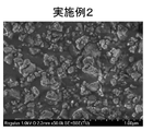
- FIG. 2B shows an SEM image taken to evaluate the particle size of the particles contained in the composition according to Example 2.
- FIG. 2C shows an SEM image taken to evaluate the particle size of the particles contained in the composition according to Example 3.
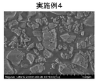
- FIG. 2D shows an SEM image taken to assess the particle size of the particles contained in the composition according to Example 4.
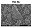
- FIG. 2E shows an SEM image taken to evaluate the particle size of the particles contained in the composition according to Example 5.
- FIG. 2F shows an SEM image taken to evaluate the particle size of the particles contained in the composition according to Example 6.
- SEM Scanning Electron Microscope
- FIG. 2G shows an SEM image taken to assess the particle size of the particles contained in the composition according to Example 7.
- FIG. 2H shows an SEM image obtained to evaluate the particle size of the particles contained in the composition according to Example 8.
- FIG. 2I shows an SEM image taken to evaluate the particle size of the particles contained in the composition according to Example 9.
- FIG. 2J shows an SEM image taken to assess the particle size of the particles contained in the composition according to Example 10.
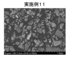
- FIG. 2K shows an SEM image taken to evaluate the particle size of the particles contained in the composition according to Example 11.
- FIG. 2L shows an SEM image taken to evaluate the particle size of the particles contained in the composition according to Example 12.
- FIG. 2M shows an SEM image taken to assess the particle size of the particles contained in the composition according to Example 13.
- FIG. 2N shows an SEM image taken to assess the particle size of the particles contained in the composition according to Example 14.
- FIG. 2O shows an SEM image obtained to evaluate the particle size of the particles contained in the composition according to Reference Example 1.
- FIG. 3 shows a schematic diagram of a pressure forming die 300 used to evaluate the ionic conductivity of solid electrolyte materials.
- 4 is a graph showing a Cole-Cole plot obtained by impedance measurement of the solid electrolyte material according to Example 1.
- FIG. FIG. 5 is a graph showing the initial discharge characteristics of the batteries according to Example 1 and Comparative Example 1;
- a composition according to the first embodiment includes a compound containing at least one selected from the group consisting of Zr, Al, and F, and Li, and a solvent.
- the compound is particulate and has an average particle size of less than 0.68 ⁇ m.
- the average particle size of the particulate compound is determined by morphological observation using an SEM image. Specifically, first, the composition according to the first embodiment is dried (for example, vacuum dried) to extract particles of the compound, and an SEM image of the particles is obtained.
- the average particle size is calculated by simply averaging the particle sizes of the remaining 30 particles after rounding them off.
- composition according to the first embodiment is suitable for improving the ionic conductivity of solid electrolyte materials.
- a solidified product (that is, a solid electrolyte material) obtained by removing the solvent from the composition according to the first embodiment is a solid electrolyte material having improved lithium ion conductivity.
- a solid electrolyte material is produced by heating the compound contained in the composition according to the first embodiment.
- the particles dispersed in the composition have a small particle size. Specifically, when the average particle size is less than 0.68 ⁇ m, the production reaction proceeds efficiently, and a solid electrolyte material with improved ionic conductivity can be obtained.
- the raw materials react with each other in the process of micronizing or dispersing the raw materials to form a precursor of the solid electrolyte material, it is expected that the production reaction of the solid electrolyte material proceeds more efficiently.
- the average particle size of the compound contained in the composition according to the first embodiment may be 0.5 ⁇ m or less, or 0.3 ⁇ m or less. 0.2 ⁇ m or less. Although the lower limit of the average particle size of the compound is not particularly limited, the average particle size may be, for example, 0.01 ⁇ m or more.
- a solid electrolyte material obtained from the composition of the first embodiment (hereinafter referred to as "solid electrolyte material according to the first embodiment") can be used to obtain a battery with excellent charge/discharge characteristics.
- An example of such a battery is an all solid state battery.
- the all-solid-state battery may be a primary battery or a secondary battery.
- the solvent contained in the composition according to the first embodiment may contain a compound having at least one functional group selected from the group consisting of an ester group and a hydroxy group.
- a compound having at least one functional group selected from the group consisting of an ester group and a hydroxy group By containing the compound having these functional groups as a solvent, the dispersion particles in the composition according to the first embodiment, that is, the particle size reduction of the compound can be efficiently progressed.
- the solvent contained in the composition according to the first embodiment may contain at least one selected from the group consisting of ⁇ -butyrolactone, propylene carbonate, butyl acetate, ethanol, dimethylsulfoxide, and tetralin.
- a compound such as LiF, ZrF 4 or AlF 3 is mixed with a solvent and the compound is pulverized to pulverize and disperse the compound. It may be made by doing it at the same time. According to such a method, synthesis, pulverization, and slurrying of the solid electrolyte material can be performed simultaneously, and it is expected that the number of steps can be reduced.
- the compound contained in the composition according to the first embodiment may be the raw material of the solid electrolyte material.
- the compounds contained in the composition according to the first embodiment may be raw materials for solid electrolytes containing Li, Zr, Al, and F, for example.
- composition according to the first embodiment may contain at least one selected from the group consisting of LiF, Li2ZrF6 , and Li3AlF6 as the compound.
- the solid electrolyte material according to the first embodiment desirably does not contain sulfur.
- a sulfur-free solid electrolyte material does not generate hydrogen sulfide even when exposed to the atmosphere, and is therefore excellent in safety.
- the sulfide solid electrolyte disclosed in Patent Document 1 can generate hydrogen sulfide when exposed to the atmosphere.
- the solid electrolyte material according to the first embodiment contains F and thus can have high oxidation resistance. This is because F has a high redox potential. On the other hand, since F has high electronegativity, it has a relatively strong bond with Li. As a result, solid electrolyte materials containing Li and F typically have low lithium ion conductivity. For example, LiBF 4 disclosed in Patent Document 2 has a low ionic conductivity of 6.67 ⁇ 10 ⁇ 9 S/cm. On the other hand, when the solid electrolyte material obtained from the composition of Embodiment 1 further contains Zr and Al in addition to Li and F, for example, high ionic conductivity of 7 ⁇ 10 ⁇ 9 S/cm or more degree.
- the solid electrolyte material according to the first embodiment may contain anions other than F in order to increase the ion conductivity of the solid electrolyte material.
- anions are Cl, Br, I, O or Se.
- the ratio of the amount of F to the total amount of anions constituting the solid electrolyte material according to the first embodiment is 0.50 or more and 1.0 or less. good too.
- the solid electrolyte material according to the first embodiment may consist essentially of Li, Zr, Al, and F.
- the solid electrolyte material according to the first embodiment consists essentially of Li, Zr, Al, and F
- the ratio (ie, mole fraction) may be 95% or greater.
- the solid electrolyte material according to the first embodiment may consist of Li, Zr, Al, and F only.
- the solid electrolyte material according to the first embodiment may contain elements that are unavoidably mixed. Examples of such elements are hydrogen, oxygen or nitrogen. Such elements can be present in the raw powder of the solid electrolyte material or in the atmosphere for manufacturing or storing the solid electrolyte material.
- the ratio of the amount of Li substance to the total amount of Zr and Al is 1.12 or more and 5.07 or less. There may be.
- the solid electrolyte material according to the first embodiment may be a material represented by the following compositional formula (1).
- Li6-(4-x)b ( Zr1 -xAlx ) bF6 (1)
- equation (1) the equations: 0 ⁇ x ⁇ 1 and 0 ⁇ b ⁇ 1.5 are satisfied.
- a solid electrolyte material containing such a crystal phase has high ionic conductivity.
- the composition according to the first embodiment contains Li, Zr, Al, and F
- a molar ratio of [6-(4-x)b]:(1-x)b:xb:6 may be satisfied.
- x and y satisfy 0 ⁇ x ⁇ 1 and 0 ⁇ b ⁇ 1.5.
- the formula: 0.01 ⁇ x ⁇ 0.99 may be satisfied in formula (1).
- the formula: 0.2 ⁇ x ⁇ 0.95 may be satisfied.
- the upper and lower limits of the range of x in formula (1) are 0.01, 0.2, 0.4, 0.5, 0.5, 0.7, 0.8, 0.95, and 0 It can be defined by any combination of numbers selected from 0.99.
- the formula: 0.7 ⁇ b ⁇ 1.3 may be satisfied in formula (1).
- the formula: 0.9 ⁇ b ⁇ 1.04 may be satisfied.
- the upper and lower limits of the range of b in formula (1) are 0.7, 0.8, 0.9, 0.96, 1, 1.04, 1.1, 1.2, and 1.3. can be defined by any combination selected from the numerical values of
- the solid electrolyte material according to the first embodiment may be Li2.8Zr0.2Al0.8F6 .
- the solid electrolyte material according to the first embodiment may be crystalline or amorphous.
- the shape of the solid electrolyte material according to the first embodiment is not limited. Examples of such shapes are acicular, spherical, or ellipsoidal.
- the solid electrolyte material obtained from the composition of the first embodiment may be particles.
- the solid electrolyte material obtained from the composition of the first embodiment may have the shape of pellets or plates.
- a composition according to the first embodiment is produced, for example, by the following method.
- a raw material composition containing a compound containing Li and at least one selected from the group consisting of Zr, Al, and F, and a solvent (for example, an organic solvent) are mixed while pulverizing in a mixing device.
- the raw material composition may further contain, in addition to the above compounds, another compound that serves as a raw material for the solid electrolyte material.
- the composition of the target solid electrolyte material is Li2.8Zr0.2Al0.8F6
- LiF, ZrF4 , and AlF3 have a molar ratio of about 2.8:0.2:0.8.
- the raw material powders may be mixed in pre-adjusted molar ratios to compensate for possible compositional changes in the synthesis process.
- Raw material powder (raw material composition) and an organic solvent are put into a mixing device such as a planetary ball mill, and mixed while pulverizing. That is, a wet ball mill is performed.
- the raw material powder may be mixed before being charged into the mixing device.
- the composition according to the first embodiment is obtained.
- pulverization of the charged raw material composition is also performed at the same time, and in the composition according to the first embodiment, the particle size of the particles of the raw material composition dispersed in the solvent is smaller than that of the charged raw material. It is expected that The particle size of the dispersed raw material composition particles can be obtained, for example, by the same method as the method for obtaining the average particle size of the particulate compound in the composition according to the first embodiment described above.
- a solid electrolyte material according to the first embodiment is obtained from the composition according to the first embodiment. For example, it is manufactured by the following method.
- a solidified product is obtained by drying the composition according to the first embodiment at a temperature corresponding to the boiling point of the solvent used.
- the reactant that is, the solid electrolyte material according to the first embodiment is obtained.
- the resulting reactant may be calcined in vacuum or in an inert atmosphere. Firing is performed at, for example, 100° C. or higher and 300° C. or lower for 1 hour or longer. In order to suppress composition change during firing, firing may be performed in a sealed container such as a quartz tube.
- a battery according to the second embodiment includes a positive electrode, an electrolyte layer, and a negative electrode.
- the electrolyte layer is provided between the positive electrode and the negative electrode.
- At least one selected from the group consisting of the positive electrode, the electrolyte layer, and the negative electrode contains the solidified material of the composition according to the first embodiment (that is, the solid electrolyte material according to the first embodiment).
- the battery according to the second embodiment contains the solid electrolyte material according to the first embodiment, it has excellent charge/discharge characteristics.
- FIG. 1 shows a cross-sectional view of a battery 1000 according to the second embodiment.
- a battery 1000 according to the second embodiment includes a positive electrode 201 , an electrolyte layer 202 and a negative electrode 203 .
- Electrolyte layer 202 is provided between positive electrode 201 and negative electrode 203 .
- a positive electrode 201 contains a positive electrode active material 204 and a solid electrolyte 100 .
- the electrolyte layer 202 contains an electrolyte material.
- the negative electrode 203 contains a negative electrode active material 205 and a solid electrolyte 100 .
- the solid electrolyte 100 includes, for example, the solid electrolyte material according to the first embodiment.
- the solid electrolyte 100 may be particles containing the solid electrolyte material according to the first embodiment as a main component.
- a particle containing the solid electrolyte material according to the first embodiment as a main component means a particle in which the component contained in the largest molar ratio is the solid electrolyte material according to the first embodiment.
- the solid electrolyte 100 may be particles made of the solid electrolyte material according to the first embodiment.
- the positive electrode 201 contains a material that can occlude and release metal ions (eg, lithium ions).
- the material is, for example, the positive electrode active material 204 .
- cathode active material 204 examples include lithium-containing transition metal oxides, transition metal fluorides, polyanions, fluorinated polyanion materials, transition metal sulfides, transition metal oxyfluorides, transition metal oxysulfides, or transition metal oxynitrides. be.
- lithium-containing transition metal oxides are Li(Ni,Co,Mn) O2 , Li(Ni,Co,Al) O2 or LiCoO2 .
- (A, B, C) means "at least one selected from the group consisting of A, B, and C.”
- the shape of the positive electrode active material 204 is not limited to a specific shape.
- the cathode active material 204 may be particles.
- the positive electrode active material 204 may have a median diameter of 0.1 ⁇ m or more and 100 ⁇ m or less.
- positive electrode active material 204 and solid electrolyte 100 can be well dispersed in positive electrode 201 . Thereby, the charge/discharge characteristics of the battery 1000 are improved.
- the positive electrode active material 204 has a median diameter of 100 ⁇ m or less, the diffusion rate of lithium in the positive electrode active material 204 is improved. This allows battery 1000 to operate at high output.
- the positive electrode active material 204 may have a larger median diameter than the solid electrolyte 100 . Thereby, the positive electrode active material 204 and the solid electrolyte 100 can be well dispersed in the positive electrode 201 .
- the ratio of the volume of the positive electrode active material 204 to the total volume of the positive electrode active material 204 and the volume of the solid electrolyte 100 is 0.30 or more and 0.95. It may be below.
- a coating layer may be formed on at least part of the surface of the positive electrode active material 204 .
- a coating layer can be formed on the surface of the positive electrode active material 204, for example, before mixing with the conductive aid and the binder.
- coating materials contained in the coating layer are sulfide solid electrolytes, oxide solid electrolytes or halide solid electrolytes.
- the coating material may contain the solid electrolyte material according to the first embodiment in order to suppress oxidative decomposition of the sulfide solid electrolyte.
- the coating material may contain an oxide solid electrolyte in order to suppress oxidative decomposition of the solid electrolyte material.
- Lithium niobate which has excellent stability at high potentials, may be used as the oxide solid electrolyte. By suppressing oxidative decomposition, an overvoltage rise of the battery 1000 can be suppressed.
- the positive electrode 201 may have a thickness of 10 ⁇ m or more and 500 ⁇ m or less.
- the electrolyte layer 202 contains an electrolyte material.
- the electrolyte material is, for example, a solid electrolyte material.
- the solid electrolyte material may include the solid electrolyte material according to the first embodiment.
- the electrolyte layer 202 may be a solid electrolyte layer.
- the electrolyte layer 202 may contain 50% by mass or more of the solid electrolyte material according to the first embodiment.
- the electrolyte layer 202 may contain 70% by mass or more of the solid electrolyte material according to the first embodiment.
- the electrolyte layer 202 may contain 90% by mass or more of the solid electrolyte material according to the first embodiment.
- the electrolyte layer 202 may consist only of the solid electrolyte material according to the first embodiment.
- the solid electrolyte material according to the first embodiment will be referred to as the first solid electrolyte material.
- a solid electrolyte material different from the first solid electrolyte material is referred to as a second solid electrolyte material.
- the electrolyte layer 202 may contain not only the first solid electrolyte material but also the second solid electrolyte material. In the electrolyte layer 202, the first solid electrolyte material and the second solid electrolyte material may be uniformly dispersed. A layer made of the first solid electrolyte material and a layer made of the second solid electrolyte material may be stacked along the stacking direction of battery 1000 .
- the battery according to the second embodiment may include the positive electrode 201, the second electrolyte layer, the first electrolyte layer, and the negative electrode 203 in this order.
- the solid electrolyte material contained in the first electrolyte layer may have a lower reduction potential than the solid electrolyte material contained in the second electrolyte layer.
- the solid electrolyte material contained in the second electrolyte layer can be used without being reduced.
- the charge/discharge efficiency of the battery 1000 can be improved.
- the first electrolyte layer may contain a sulfide solid electrolyte in order to suppress reductive decomposition of the solid electrolyte material.
- the second electrolyte layer may contain the first solid electrolyte material. Since the first solid electrolyte material has high oxidation resistance, it is possible to realize a battery with excellent charge/discharge characteristics.
- the electrolyte layer 202 may consist only of the second solid electrolyte material.
- the electrolyte layer 202 may have a thickness of 1 ⁇ m or more and 1000 ⁇ m or less. When the electrolyte layer 202 has a thickness of 1 ⁇ m or more, the short circuit between the positive electrode 201 and the negative electrode 203 is less likely to occur. If the electrolyte layer 202 has a thickness of 1000 ⁇ m or less, the battery 1000 can operate at high power.
- Examples of the second solid electrolyte material are Li2MgX4 , Li2FeX4 , Li(Al,Ga,In) X4 , Li3 ( Al ,Ga,In) X6 , or LiI.
- X is at least one selected from the group consisting of F, Cl, Br and I.
- the electrolyte layer 202 may have a thickness of 1 ⁇ m or more and 1000 ⁇ m or less.
- the negative electrode 203 contains a material capable of intercalating and deintercalating metal ions (eg, lithium ions).
- the material is, for example, the negative electrode active material 205 .
- Examples of the negative electrode active material 205 are metal materials, carbon materials, oxides, nitrides, tin compounds, or silicon compounds.
- the metallic material may be a single metal or an alloy.
- Examples of metallic materials are lithium metal or lithium alloys.
- Examples of carbon materials are natural graphite, coke, ungraphitized carbon, carbon fibers, spherical carbon, artificial graphite, or amorphous carbon. From the viewpoint of capacity density, suitable examples of negative electrode active materials are silicon (ie, Si), tin (ie, Sn), silicon compounds, or tin compounds.
- the negative electrode active material 205 may be selected in consideration of the reduction resistance of the solid electrolyte material contained in the negative electrode 203 .
- the negative electrode active material 205 may be a material capable of intercalating and deintercalating lithium ions at 0.27 V or higher with respect to lithium.
- examples of such negative electrode active materials are titanium oxide, indium metal, or lithium alloys.
- examples of titanium oxides are Li4Ti5O12 , LiTi2O4 , or TiO2 .
- the shape of the negative electrode active material 205 is not limited to a specific shape.
- the negative electrode active material 205 may be particles.
- the negative electrode active material 205 may have a median diameter of 0.1 ⁇ m or more and 100 ⁇ m or less.
- negative electrode active material 205 and solid electrolyte 100 can be well dispersed in negative electrode 203 . Thereby, the charge/discharge characteristics of the battery 1000 are improved.
- the negative electrode active material 205 has a median diameter of 100 ⁇ m or less, the diffusion rate of lithium in the negative electrode active material 205 is improved. This allows battery 1000 to operate at high output.
- the negative electrode active material 205 may have a larger median diameter than the solid electrolyte 100 . Thereby, the negative electrode active material 205 and the solid electrolyte 100 can be well dispersed in the negative electrode 203 .
- the ratio of the volume of the negative electrode active material 205 to the total volume of the negative electrode active material 205 and the volume of the solid electrolyte 100 is 0.30 or more and 0.95. It may be below.
- the negative electrode 203 may have a thickness of 10 ⁇ m or more and 500 ⁇ m or less.
- At least one selected from the group consisting of positive electrode 201, electrolyte layer 202, and negative electrode 203 contains a second solid electrolyte material for the purpose of enhancing ion conductivity, chemical stability, and electrochemical stability. may be
- the second solid electrolyte material may be a sulfide solid electrolyte.
- sulfide solid electrolytes are Li 2 SP 2 S 5 , Li 2 S-SiS 2 , Li 2 S-B 2 S 3 , Li 2 S-GeS 2 , Li 3.25 Ge 0.25 P 0.75 S 4 , or Li10GeP2S12 . _
- the negative electrode 203 may contain a sulfide solid electrolyte in order to suppress reductive decomposition of the solid electrolyte material.
- the contact of the first solid electrolyte material with the negative electrode active material can be suppressed. As a result, the internal resistance of battery 1000 can be reduced.
- the second solid electrolyte material may be an oxide solid electrolyte.
- oxide solid electrolytes are (i) NASICON-type solid electrolytes such as LiTi2 ( PO4 ) 3 or elemental substitutions thereof; (ii) perovskite-type solid electrolytes such as (LaLi) TiO3 ; (iii) LISICON -type solid electrolytes such as Li14ZnGe4O16 , Li4SiO4 , LiGeO4 or elemental substitutions thereof ; (iv) garnet- type solid electrolytes such as Li7La3Zr2O12 or its elemental substitutions, or ( v) Li3PO4 or its N substitutions, is.
- NASICON-type solid electrolytes such as LiTi2 ( PO4 ) 3 or elemental substitutions thereof
- perovskite-type solid electrolytes such as (LaLi) TiO3 ;
- LISICON -type solid electrolytes such as Li14ZnGe4O16 , Li4SiO4 , LiGeO4
- the second solid electrolyte material may be a halide solid electrolyte.
- halide solid electrolytes are Li2MgX4 , Li2FeX4 , Li(Al,Ga,In) X4 , Li3 ( Al ,Ga,In) X6 , or LiI.
- X is at least one selected from the group consisting of F, Cl, Br and I.
- halide solid electrolyte is the compound represented by LiaMebYcZ6 .
- Me is at least one selected from the group consisting of metal elements other than Li and Y and metalloid elements.
- Z is at least one selected from the group consisting of F, Cl, Br and I;
- m represents the valence of Me.
- Simetallic elements are B, Si, Ge, As, Sb, and Te.
- Metallic element means all elements contained in Groups 1 to 12 of the periodic table (excluding hydrogen), and all elements contained in Groups 13 to 16 of the periodic table (however, , B, Si, Ge, As, Sb, Te, C, N, P, O, S, and Se).
- Me is the group consisting of Mg, Ca, Sr, Ba, Zn, Sc, Al, Ga, Bi, Zr, Hf, Ti, Sn, Ta, and Nb to improve the ionic conductivity of the halide solid electrolyte. It may be at least one selected from.
- the halide solid electrolyte may be Li3YCl6 or Li3YBr6 .
- the second solid electrolyte material may be an organic polymer solid electrolyte.
- organic polymer solid electrolytes examples include polymeric compounds and lithium salt compounds.
- the polymer compound may have an ethylene oxide structure. Since a polymer compound having an ethylene oxide structure can contain a large amount of lithium salt, the ionic conductivity can be further increased.
- lithium salts are LiPF6 , LiBF4 , LiSbF6, LiAsF6 , LiSO3CF3 , LiN ( SO2CF3 ) 2 , LiN( SO2C2F5 ) 2 , LiN( SO2CF3 ) . ( SO2C4F9 ) , or LiC ( SO2CF3 )3 .
- One lithium salt selected from these may be used alone. Alternatively, a mixture of two or more lithium salts selected from these may be used.
- At least one selected from the group consisting of the positive electrode 201, the electrolyte layer 202, and the negative electrode 203 is composed of a non-aqueous electrolyte liquid, a gel electrolyte, or an ion in order to facilitate the transfer of lithium ions and improve the output characteristics of the battery. It may contain liquids.
- the non-aqueous electrolyte contains a non-aqueous solvent and a lithium salt dissolved in the non-aqueous solvent.
- non-aqueous solvents examples include cyclic carbonate solvents, chain carbonate solvents, cyclic ether solvents, chain ether solvents, cyclic ester solvents, chain ester solvents, or fluorine solvents.
- cyclic carbonate solvents are ethylene carbonate, propylene carbonate, or butylene carbonate.
- linear carbonate solvents are dimethyl carbonate, ethyl methyl carbonate, or diethyl carbonate.
- examples of cyclic ether solvents are tetrahydrofuran, 1,4-dioxane, or 1,3-dioxolane.
- Chain ether solvents are 1,2-dimethoxyethane or 1,2-diethoxyethane.
- An example of a cyclic ester solvent is ⁇ -butyrolactone.
- An example of a linear ester solvent is methyl acetate.
- fluorosolvents are fluoroethylene carbonate, methyl fluoropropionate, fluorobenzene, fluoroethyl methyl carbonate, or fluorodimethylene carbonate.
- One non-aqueous solvent selected from these may be used alone. Alternatively, a combination of two or more non-aqueous solvents selected from these may be used.
- lithium salts are LiPF6 , LiBF4 , LiSbF6, LiAsF6 , LiSO3CF3 , LiN ( SO2CF3 ) 2 , LiN( SO2C2F5 ) 2 , LiN( SO2CF3 ) . ( SO2C4F9 ) , or LiC ( SO2CF3 )3 .
- One lithium salt selected from these may be used alone. Alternatively, a mixture of two or more lithium salts selected from these may be used.
- the lithium salt concentration is, for example, in the range of 0.5 mol/L or more and 2 mol/L or less.
- a polymer material impregnated with a non-aqueous electrolyte can be used as the gel electrolyte.
- examples of polymeric materials are polyethylene oxide, polyacrylonitrile, polyvinylidene fluoride, polymethyl methacrylate, or polymers with ethylene oxide linkages.
- ionic liquids examples include (i) aliphatic chain quaternary salts such as tetraalkylammonium or tetraalkylphosphonium; (ii) aliphatic cyclic ammoniums such as pyrrolidiniums, morpholiniums, imidazoliniums, tetrahydropyrimidiniums, piperaziniums, or piperidiniums; or (iii) nitrogen-containing heteroatoms such as pyridiniums or imidazoliums ring aromatic cations, is.
- aliphatic chain quaternary salts such as tetraalkylammonium or tetraalkylphosphonium
- aliphatic cyclic ammoniums such as pyrrolidiniums, morpholiniums, imidazoliniums, tetrahydropyrimidiniums, piperaziniums, or piperidiniums
- nitrogen-containing heteroatoms such as pyridin
- Examples of anions contained in the ionic liquid are PF 6 ⁇ , BF 4 ⁇ , SbF 6 ⁇ , AsF 6 ⁇ , SO 3 CF 3 ⁇ , N(SO 2 CF 3 ) 2 ⁇ , N(SO 2 C 2 F 5 ) 2- , N( SO2CF3 ) ( SO2C4F9 )- , or C ( SO2CF3 ) 3- .
- the ionic liquid may contain a lithium salt.
- At least one selected from the group consisting of the positive electrode 201, the electrolyte layer 202, and the negative electrode 203 may contain a binder in order to improve adhesion between particles.
- binders include polyvinylidene fluoride, polytetrafluoroethylene, polyethylene, polypropylene, aramid resin, polyamide, polyimide, polyamideimide, polyacrylonitrile, polyacrylic acid, polyacrylic acid methyl ester, polyacrylic acid ethyl ester, Polyacrylic acid hexyl ester, polymethacrylic acid, polymethacrylic acid methyl ester, polymethacrylic acid ethyl ester, polymethacrylic acid hexyl ester, polyvinyl acetate, polyvinylpyrrolidone, polyether, polyether sulfone, hexafluoropolypropylene, styrene-butadiene rubber , or carboxymethyl cellulose.
- Copolymers can also be used as binders.
- binders are tetrafluoroethylene, hexafluoroethylene, hexafluoropropylene, perfluoroalkyl vinyl ethers, vinylidene fluoride, chlorotrifluoroethylene, ethylene, propylene, pentafluoropropylene, fluoromethyl vinyl ether, acrylic acid , and hexadiene.
- a mixture of two or more materials selected from these may be used as the binder.
- At least one selected from the positive electrode 201 and the negative electrode 203 may contain a conductive aid in order to improve electronic conductivity.
- Examples of conductive aids are (i) graphites such as natural or artificial graphite; (ii) carbon blacks such as acetylene black or ketjen black; (iii) conductive fibers such as carbon or metal fibers; (iv) carbon fluoride, (v) metal powders such as aluminum; (vi) conductive whiskers such as zinc oxide or potassium titanate; (vii) a conductive metal oxide such as titanium oxide, or (viii) a conductive polymeric compound such as polyaniline, polypyrrole, or polythiophene; is.
- the conductive aid (i) or (ii) may be used.
- Examples of the shape of the battery according to the second embodiment are coin-shaped, cylindrical, rectangular, sheet-shaped, button-shaped, flat-shaped, and laminated.
- a material for forming a positive electrode, a material for forming an electrolyte layer, and a material for forming a negative electrode are prepared, and the positive electrode, the electrolyte layer, and the negative electrode are arranged in this order by a known method. It may also be manufactured by making laminated laminates.
- Example 1 (Production of composition)
- a molar ratio of 2:0.8 was prepared.
- These raw material powders were put into a 45 cc planetary ball mill pod together with 1 mm ⁇ balls (25 g).
- ⁇ -Butyrolactone (GBL) as an organic solvent was added dropwise to the pod so that the solid content ratio was 50%.
- the solid content ratio is calculated by ⁇ (mass of input raw material)/(mass of input raw material+mass of input solvent) ⁇ 100.
- a planetary ball mill was used for milling at 500 rpm for 12 hours.
- the composition according to Example 1 was obtained by separating the balls after milling.
- the particles were leveled with a mortar as necessary.
- a SEM (Regulus 8230, Hitachi High-Tech Innovations) was used for morphological observation.
- 40 primary particles are randomly selected, the unidirectional diameter of the selected primary particles is measured, the particle diameter of 10 particles from the bottom of the 40 particle diameters is discarded, and the remaining The average particle size was calculated by simple averaging the particle sizes for 30 particles.
- the observation magnification was 50,000 times.
- 2A shows an SEM image taken to evaluate the particle size of the particles contained in the composition according to Example 1.
- FIG. The average particle size of the dispersed particles of Example 1 was 0.127 ⁇ m.
- Example 1 (Preparation of solid electrolyte material) The composition according to Example 1 was dried at 200° C. for 1 hour under nitrogen flow using a heating mantle. A powder of the solid electrolyte material according to Example 1 was obtained by pulverizing the resulting solidified material with a mortar. The solid electrolyte material according to Example 1 had a composition represented by Li2.8Zr0.2Al0.8F6 .
- FIG. 3 shows a schematic diagram of a pressure forming die 300 used to evaluate the ionic conductivity of solid electrolyte materials.
- the pressure forming die 300 had a punch upper part 301 , a frame mold 302 and a punch lower part 303 .
- the frame mold 302 was made of insulating polycarbonate.
- Punch top 301 and punch bottom 303 were made of electronically conductive stainless steel.
- the ionic conductivity of the solid electrolyte material according to Example 1 was evaluated by the following method.
- the inside of the pressure molding die 300 was filled with the powder of the solid electrolyte material according to Example 1. Inside the pressing die 300, a pressure of 400 MPa was applied to the solid electrolyte material according to Example 1 using the upper punch 301 and the lower punch 303. As shown in FIG.
- the upper punch 301 and lower punch 303 were connected to a potentiostat (BioLogic, VSP300) equipped with a frequency response analyzer.
- the punch upper part 301 was connected to the working electrode and the terminal for potential measurement.
- the punch bottom 303 was connected to the counter and reference electrodes.
- the impedance of the solid electrolyte material was measured by electrochemical impedance measurement at room temperature.
- FIG. 4 is a graph showing a Cole-Cole plot obtained by impedance measurement of the solid electrolyte material according to Example 1.
- the real value of the impedance at the measurement point where the absolute value of the phase of the complex impedance was the smallest was regarded as the resistance to ion conduction of the solid electrolyte material. See the arrow R SE shown in FIG. 4 for the real value.
- the ionic conductivity was calculated based on the following formula (2) using the resistance value.
- ⁇ (R SE ⁇ S/t) ⁇ 1 (2)
- ⁇ represents ionic conductivity.
- S represents the contact area of the solid electrolyte material with the punch upper part 301 . That is, S is equal to the cross-sectional area of the hollow portion of the frame mold 302 in FIG.
- R SE represents the resistance value of the solid electrolyte material in impedance measurement.
- t represents the thickness of the solid electrolyte material. That is, t represents the thickness of the layer formed from the solid electrolyte material powder 101 in FIG.
- Li 3 PS 4 (57.41 mg), the solid electrolyte material according to Example 1 (26 mg), and the positive electrode mixture (9.1 mg) were laminated in this order. was done.
- a pressure of 300 MPa was applied to the obtained laminate to form a first electrolyte layer, a second electrolyte layer, and a positive electrode. That is, the second electrolyte layer formed from the solid electrolyte material according to Example 1 was sandwiched between the first electrolyte layer and the positive electrode.
- the thicknesses of the first electrolyte layer and the second electrolyte layer were 450 ⁇ m and 150 ⁇ m, respectively.
- metal Li (thickness: 200 ⁇ m) was laminated on the first electrolyte layer.
- current collectors made of stainless steel were attached to the positive and negative electrodes, and current collecting leads were attached to the current collectors.
- Example 1 a battery according to Example 1 was obtained.
- (Charging and discharging test) 5 is a graph showing the initial discharge characteristics of the battery according to Example 1.
- FIG. Initial charge/discharge characteristics were measured by the following method.
- the battery according to Example 1 was placed in a constant temperature bath at 85°C.
- a cell according to Example 1 was charged at a current density of 13.5 ⁇ A/cm 2 until a voltage of 4.2 V was reached. This current density corresponds to a 0.01C rate.
- Example 1 The cell according to Example 1 was then discharged at a current density of 13.5 ⁇ A/cm 2 until a voltage of 2.5 V was reached.
- the battery according to Example 1 had an initial discharge capacity of 943 ⁇ Ah.
- Example 2 to 14 (Preparation of composition and solid electrolyte material)
- Table 1 shows the type of solvent, solid content ratio, ball diameter, amount of balls, and processing time in the milling treatment of the composition.
- compositions according to Examples 2 to 13 were obtained in the same manner as in Example 1 except for the conditions shown in Table 1.
- Example 2 A charge/discharge test was performed in the same manner as in Example 1 using the batteries according to Examples 2 to 14. As a result, the batteries according to Examples 2 to 14 were charged and discharged as well as the battery according to Example 1.
- FIG. 2O shows an SEM image obtained to evaluate the particle size of the particles contained in the composition according to Reference Example 1.
- the ionic conductivity measured at 25°C was too large to be measured. This is probably because the average particle size of the particles of the compound contained in the composition according to Reference Example 1 was as large as 0.68 ⁇ m or more, and the compound (that is, the solid electrolyte material) with the desired composition was not formed.
- a battery according to Comparative Example 1 was obtained in the same manner as in Example 1, except that the solid electrolyte material according to Comparative Example 2 was used as the positive electrode mixture and the solid electrolyte used for the electrolyte layer.
- Example 1 A charge/discharge test was performed in the same manner as in Example 1 using the battery according to Comparative Example 1.
- 5 is a graph showing the initial discharge characteristics of the battery according to Comparative Example 1.
- FIG. As a result, the initial discharge capacity of the battery according to Comparative Example 1 was 0.01 ⁇ Ah or less. That is, the battery according to Comparative Example 1 was neither charged nor discharged.
- compositions of Examples 1 to 13 were obtained by pulverizing the raw material composition by a wet ball mill in GBL, which is the solvent constituting the composition
- the composition of Example 14 was obtained by dispersing particles of a raw material composition that had been pulverized in advance in GBL, a solvent that constitutes the composition.
- the solid electrolyte material produced using the composition of Example 14 had the same level of ionic conductivity as the solid electrolyte materials produced using the compositions of Examples 1-13. For this reason, it is not essential to pulverize the raw material composition in the solvent that constitutes the composition, and a composition obtained by using a raw material composition that has been pulverized in advance and dispersing it in a solvent is also a solid. It was confirmed that it is suitable for improving the ionic conductivity of the electrolyte material.
- the powder obtained by drying the composition according to Reference Example 1 did not have the desired composition as described above, so the lithium ion conductivity could not be confirmed.
- the composition according to the present disclosure can provide a solid electrolyte material having high lithium ion conductivity and is suitable for providing batteries that can be charged and discharged well.
- composition of the present disclosure is used, for example, in all-solid lithium ion secondary batteries.
Landscapes
- Chemical & Material Sciences (AREA)
- Electrochemistry (AREA)
- Engineering & Computer Science (AREA)
- Chemical Kinetics & Catalysis (AREA)
- General Chemical & Material Sciences (AREA)
- Manufacturing & Machinery (AREA)
- Inorganic Chemistry (AREA)
- Physics & Mathematics (AREA)
- Condensed Matter Physics & Semiconductors (AREA)
- General Physics & Mathematics (AREA)
- Organic Chemistry (AREA)
- Materials Engineering (AREA)
- Secondary Cells (AREA)
- Conductive Materials (AREA)
Priority Applications (4)
| Application Number | Priority Date | Filing Date | Title |
|---|---|---|---|
| CN202280051725.6A CN117715872A (zh) | 2021-08-06 | 2022-07-15 | 组合物、电池及组合物的制造方法 |
| EP22852815.4A EP4382483A1 (en) | 2021-08-06 | 2022-07-15 | Composition, battery, and method for manufacturing composition |
| JP2023540227A JPWO2023013391A1 (zh) | 2021-08-06 | 2022-07-15 | |
| US18/419,631 US20240204243A1 (en) | 2021-08-06 | 2024-01-23 | Composition, battery, and method for producing composition |
Applications Claiming Priority (2)
| Application Number | Priority Date | Filing Date | Title |
|---|---|---|---|
| JP2021130376 | 2021-08-06 | ||
| JP2021-130376 | 2021-08-06 |
Related Child Applications (1)
| Application Number | Title | Priority Date | Filing Date |
|---|---|---|---|
| US18/419,631 Continuation US20240204243A1 (en) | 2021-08-06 | 2024-01-23 | Composition, battery, and method for producing composition |
Publications (1)
| Publication Number | Publication Date |
|---|---|
| WO2023013391A1 true WO2023013391A1 (ja) | 2023-02-09 |
Family
ID=85155951
Family Applications (1)
| Application Number | Title | Priority Date | Filing Date |
|---|---|---|---|
| PCT/JP2022/027921 WO2023013391A1 (ja) | 2021-08-06 | 2022-07-15 | 組成物、電池、および組成物の製造方法 |
Country Status (5)
| Country | Link |
|---|---|
| US (1) | US20240204243A1 (zh) |
| EP (1) | EP4382483A1 (zh) |
| JP (1) | JPWO2023013391A1 (zh) |
| CN (1) | CN117715872A (zh) |
| WO (1) | WO2023013391A1 (zh) |
Citations (9)
| Publication number | Priority date | Publication date | Assignee | Title |
|---|---|---|---|---|
| JP2008277170A (ja) | 2007-04-27 | 2008-11-13 | Ohara Inc | リチウム二次電池およびリチウム二次電池用の電極 |
| JP2011129312A (ja) | 2009-12-16 | 2011-06-30 | Toyota Motor Corp | 硫化物固体電解質材料の製造方法、硫化物固体電解質材料およびリチウム電池 |
| CN102443236A (zh) * | 2010-09-30 | 2012-05-09 | 比亚迪股份有限公司 | 一种聚合物电解质膜及其制备方法、以及一种聚合物锂离子电池 |
| JP2016004708A (ja) * | 2014-06-18 | 2016-01-12 | パナソニックIpマネジメント株式会社 | リチウムイオン二次電池用正極活物質およびその製造方法、ならびにそれを用いたリチウムイオン二次電池 |
| JP2018045965A (ja) * | 2016-09-16 | 2018-03-22 | 株式会社東芝 | 非水電解質電池、電池パック及び車両 |
| WO2019181909A1 (ja) * | 2018-03-19 | 2019-09-26 | Tdk株式会社 | 全固体電池 |
| JP2020095934A (ja) * | 2018-11-28 | 2020-06-18 | パナソニックIpマネジメント株式会社 | 固体電解質およびそれを備えた蓄電デバイス |
| WO2020175171A1 (ja) * | 2019-02-28 | 2020-09-03 | パナソニックIpマネジメント株式会社 | 電解質材料およびそれを用いた電池 |
| WO2021161604A1 (ja) * | 2020-02-14 | 2021-08-19 | パナソニックIpマネジメント株式会社 | 固体電解質材料およびそれを用いた電池 |
-
2022
- 2022-07-15 JP JP2023540227A patent/JPWO2023013391A1/ja active Pending
- 2022-07-15 WO PCT/JP2022/027921 patent/WO2023013391A1/ja active Application Filing
- 2022-07-15 EP EP22852815.4A patent/EP4382483A1/en active Pending
- 2022-07-15 CN CN202280051725.6A patent/CN117715872A/zh active Pending
-
2024
- 2024-01-23 US US18/419,631 patent/US20240204243A1/en active Pending
Patent Citations (9)
| Publication number | Priority date | Publication date | Assignee | Title |
|---|---|---|---|---|
| JP2008277170A (ja) | 2007-04-27 | 2008-11-13 | Ohara Inc | リチウム二次電池およびリチウム二次電池用の電極 |
| JP2011129312A (ja) | 2009-12-16 | 2011-06-30 | Toyota Motor Corp | 硫化物固体電解質材料の製造方法、硫化物固体電解質材料およびリチウム電池 |
| CN102443236A (zh) * | 2010-09-30 | 2012-05-09 | 比亚迪股份有限公司 | 一种聚合物电解质膜及其制备方法、以及一种聚合物锂离子电池 |
| JP2016004708A (ja) * | 2014-06-18 | 2016-01-12 | パナソニックIpマネジメント株式会社 | リチウムイオン二次電池用正極活物質およびその製造方法、ならびにそれを用いたリチウムイオン二次電池 |
| JP2018045965A (ja) * | 2016-09-16 | 2018-03-22 | 株式会社東芝 | 非水電解質電池、電池パック及び車両 |
| WO2019181909A1 (ja) * | 2018-03-19 | 2019-09-26 | Tdk株式会社 | 全固体電池 |
| JP2020095934A (ja) * | 2018-11-28 | 2020-06-18 | パナソニックIpマネジメント株式会社 | 固体電解質およびそれを備えた蓄電デバイス |
| WO2020175171A1 (ja) * | 2019-02-28 | 2020-09-03 | パナソニックIpマネジメント株式会社 | 電解質材料およびそれを用いた電池 |
| WO2021161604A1 (ja) * | 2020-02-14 | 2021-08-19 | パナソニックIpマネジメント株式会社 | 固体電解質材料およびそれを用いた電池 |
Also Published As
| Publication number | Publication date |
|---|---|
| EP4382483A1 (en) | 2024-06-12 |
| JPWO2023013391A1 (zh) | 2023-02-09 |
| CN117715872A (zh) | 2024-03-15 |
| US20240204243A1 (en) | 2024-06-20 |
Similar Documents
| Publication | Publication Date | Title |
|---|---|---|
| JP7417925B2 (ja) | 固体電解質材料、および、電池 | |
| JP7417927B2 (ja) | 固体電解質材料、および、電池 | |
| WO2019146219A1 (ja) | 固体電解質材料、および、電池 | |
| WO2019135321A1 (ja) | 固体電解質材料、および、電池 | |
| JP7432897B2 (ja) | 固体電解質材料およびそれを用いた電池 | |
| WO2021186809A1 (ja) | 固体電解質材料およびそれを用いた電池 | |
| JP7535712B2 (ja) | 固体電解質材料およびこれを用いた電池 | |
| WO2023013305A1 (ja) | 正極材料、それを用いた電池、および電池の充電方法 | |
| WO2021186833A1 (ja) | 固体電解質材料およびそれを用いた電池 | |
| JP7496509B2 (ja) | 固体電解質材料およびこれを用いた電池 | |
| JP7417951B2 (ja) | リチウムイオン伝導性固体電解質材料、およびこれを用いた電池 | |
| JP7329776B2 (ja) | 固体電解質材料、およびこれを用いた電池 | |
| JP7535711B2 (ja) | 固体電解質材料およびこれを用いた電池 | |
| WO2023013232A1 (ja) | 固体電解質材料およびそれを用いた電池 | |
| WO2021186845A1 (ja) | 固体電解質材料およびそれを用いた電池 | |
| WO2023013391A1 (ja) | 組成物、電池、および組成物の製造方法 | |
| WO2023042567A1 (ja) | 組成物、電池、および組成物の製造方法 | |
| WO2023013306A1 (ja) | 固体電解質材料およびそれを用いた電池 | |
| WO2023042560A1 (ja) | 固体電解質材料およびそれを用いた電池 | |
| WO2023013390A1 (ja) | 固体電解質材料およびそれを用いた電池 | |
| WO2022259749A1 (ja) | 固体電解質材料および電池 | |
| WO2022249762A1 (ja) | 固体電解質材料およびそれを用いた電池 | |
| WO2022219846A1 (ja) | 固体電解質材料およびそれを用いた電池 | |
| WO2023013206A1 (ja) | 固体電解質材料およびそれを用いた電池 | |
| WO2022215337A1 (ja) | 固体電解質材料およびそれを用いた電池 |
Legal Events
| Date | Code | Title | Description |
|---|---|---|---|
| 121 | Ep: the epo has been informed by wipo that ep was designated in this application |
Ref document number: 22852815 Country of ref document: EP Kind code of ref document: A1 |
|
| WWE | Wipo information: entry into national phase |
Ref document number: 2023540227 Country of ref document: JP |
|
| WWE | Wipo information: entry into national phase |
Ref document number: 202280051725.6 Country of ref document: CN |
|
| WWE | Wipo information: entry into national phase |
Ref document number: 202447005726 Country of ref document: IN |
|
| NENP | Non-entry into the national phase |
Ref country code: DE |
|
| ENP | Entry into the national phase |
Ref document number: 2022852815 Country of ref document: EP Effective date: 20240306 |